Quantcast
Channel: SparkFun Tutorials
Viewing all 1114 articles
Browse latest View live

Integrated Circuits

$
0
0

Integrated Circuits a learn.sparkfun.com tutorial

Introduction

Integrated circuits (ICs) are a keystone of modern electronics. They are the heart and brains of most circuits. They are the ubiquitous little black “chips” you find on just about every circuit board. Unless you’re some kind of crazy, analog electronics wizard, you’re likely to have at least one IC in every electronics project you build, so it’s important to understand them, inside and out.

Example of ICs on a PCB

Integrated circuits are the little black “chips”, found all over embedded electronics.

An IC is a collection of electronic components – resistors, transistors, capacitors, etc. – all stuffed into a tiny chip, and connected together to achieve a common goal. They come in all sorts of flavors: single-circuit logic gates, op amps, 555 timers, voltage regulators, motor controllers, microcontrollers, microprocessors, FPGAs…the list just goes on-and-on.

This tutorial covers the general basics of ICs, topics like:

  • The make-up of an IC
  • Common IC packages
  • Identifying ICs
  • Commonly used ICs

Consider Reading

Integrated circuits are one of the more fundamental concepts of electronics. They do build on some previous knowledge, though, so if you aren’t familiar with these topics, consider reading their tutorials first…

Inside the IC

When we think integrated circuits, little black chips are what come to mind. But what’s inside that black box?

Internal view of an IC

The guts of an integrated circuit, visible after removing the top.

The real “meat” to an IC is a complex layering of semiconductor wafers, copper, and other materials, which interconnect to form transistors, resistors or other components in a circuit. The cut and formed combination of these wafers is called a die.

Overview of internal IC

An overview of an IC die.

While the IC itself is tiny, the wafers of semiconductor and layers of copper it consists of are incredibly thin. The connections between the layers are very intricate. Here’s a zoomed in section of the die above:

Microscopic view of an IC

An IC die is the circuit in its smallest possible form, too small to solder or connect to. To make our job of connecting to the IC easier, we package the die. The IC package turns the delicate, tiny die, into the black chip we’re all familiar with.

IC Packages

The package is what encapsulates the integrated circuit die and splays it out into a device we can more easily connect to. Each outer connection on the die is connected via a tiny piece of gold wire to a pad or pin on the package. Pins are the silver, extruding terminals on an IC, which go on to connect to other parts of a circuit. These are of utmost importance to us, because they’re what will go on to connect to the rest of the components and wires in a circuit.

There are many different types of packages, each of which has unique dimensions, mounting-types, and/or pin-counts.

Package variety chart

Polarity Marking and Pin Numbering

All ICs are polarized, and every pin is unique in terms of both location and function. This means the package has to have some way to convey which pin is which. Most ICs will use either a notch or a dot to indicate which pin is the first pin. (Sometimes both, sometimes one or the other.)

Package with notch/dot labeled

Once you know where the first pin is, the remaining pin numbers increase sequentially as you move counter-clockwise around the chip.

DIP pin numbering

Mounting Style

One of the main distinguishing package type characteristics is the way they mount to a circuit board. All packages fall into one of two mounting types: through-hole (PTH) or surface-mount (SMD or SMT). Through-hole packages are generally bigger, and much easier to work with. They’re designed to be stuck through one side of a board and soldered to the other side.

Surface-mount packages range in size from small to minuscule. They are all designed to sit on one side of a circuit board and be soldered to the surface. The pins of a SMD package either extrude out the side, perpendicular to the chip, or are sometimes arranged in a matrix on the bottom of the chip. ICs in this form factor are not very “hand-assembly-friendly.” They usually require special tools to aid in the process.

DIP (Dual in-line packages)

DIP, short for dual in-line package, is the most common through-hole IC package you’ll encounter. These little chips have two parallel rows of pins extending perpendicularly out of a rectangular, black, plastic housing.

DIP package example

The 28-pin ATmega328 is one of the more popular DIP-packaged microcontrollers (thanks, Arduino!).

Each of the pins on a DIP IC are spaced by 0.1" (2.54mm), which is a standard spacing and perfect for fitting into breadboards and other prototyping boards. The overall dimensions of a DIP package depend on its pin count, which may be anywhere from four to 64.

The area between each row of pins is perfectly spaced to allow DIP ICs to straddle the center area of a breadboard. This provides each of the pins its own row in the board, and it makes sure they don’t short to each other.

DIP chips on a breadboard

Aside from being used in breadboards, DIP ICs can also be soldered into PCBs. They’re inserted into one side of the board and soldered into place on the other side. Sometimes, instead of soldering directly to the IC, it’s a good idea to socket the chip. Using sockets allows for a DIP IC to be removed and swapped out, if it happens to “let its blue smoke out.”

alt text

A regular DIP socket (top) and a ZIF socket with and without an IC.

Surface-Mount (SMD/SMT) Packages

There is a huge variety of surface-mount package types these days. In order to work with surface-mount packaged ICs, you usually need a custom printed circuit board (PCB) made for them, which has a matching pattern of copper on which they’re soldered.

Here are a few of the more common SMD package types out there, ranging in hand-solderability from “doable” to “doable, but only with special tools” to “doable only with very special, usually automated tools”.

Small-Outline (SOP)

Small-outline IC (SOIC) packages are the surface-mount cousin of the DIP. It’s what you’d get if you bent all the pins on a DIP outward, and shrunk it down to size. With a steady hand, and a close eye, these packages are among the easiest SMD parts to hand solder. On SOIC packages, each pin is usually spaced by about 0.05" (1.27mm) from the next.

The SSOP (shrink small-outline package) is an even smaller version of SOIC packages. Other, similar IC packages include TSOP (thin small-outline package) and TSSOP (thin-shrink small-outline package).

Example of SSOP mounted, quarter added for size-comparison

A 16-Channel Multiplexer (CD74HC4067) in a 24-pin SSOP package. Mounted on a board in the middle (quarter added for size-comparison).

A lot of the more simple, single-task-oriented ICs like the MAX232 or multiplexers come in SOIC or SSOP forms.

Quad Flat Packages

Splaying IC pins out in all four directions gets you something that might look like a quad flat package (QFP). QFP ICs might have anywhere from eight pins per side (32 total) to upwards of seventy (300+ total). The pins on a QFP IC are usually spaced by anywhere from 0.4mm to 1mm. Smaller variants of the standard QFP package include thin (TQFP), very thin (VQFP), and low-profile (LQFP) packages.

TQFP example package

The ATmega32U4 in a 44-pin (11 on each side) TQFP package.

If you sanded the legs off a QFP IC, you get something that might look like a quad-flat no-leads (QFN) package. The connections on QFN packages are tiny, exposed pads on the bottom corner edges of the IC. Sometimes they wrap around, and are exposed on both the side and bottom, other packages only expose the pad on the bottom of the chip.

Example of QFN package

The multitalented MPU-6050 IMU sensor comes in a relatively tiny QFN package, with 24 total pins hiding on the bottom edge of the IC.

Thin (TQFN), very thin (VQFN), and micro-lead (MLF) packages are smaller variations of the standard QFN package. There are even dual no-lead (DFN) and thin-dual no-lead (TDFN) packages, which have pins on just two of the sides.

Many microprocessors, sensors, and other modern ICs come in QFP or QFN packages. The popular ATmega328 microcontroller is offered in both a TQFP package and a QFN-type (MLF) form, while a tiny accelerometer/gyroscope like the MPU-6050 comes in a miniscule QFN form.

Ball Grid Arrays

Finally, for really advanced ICs, there are ball grid array (BGA) packages. These are amazingly intricate little packages where little balls of solder are arranged in a 2-D grid on the bottom of the IC. Sometimes the solder balls are attached directly to the die!

Example of BGA package

BGA packages are usually reserved for advanced microprocessors, like those on the pcDuino or Raspberry Pi.

If you can hand solder a BGA-packaged IC, consider yourself a master solderer. Usually, to put these packages onto a PCB requires an automated procedure involving pick-and-place machines and reflow ovens.

Common ICs

Integrated circuits are prevalent in so many forms across electronics, it’s hard to cover everything. Here are a few of the more common ICs you might encounter in educational electronics.

Logic Gates, Timers, Shift Registers, Etc.

Logic gates, the building blocks of much more ICs themselves, can be packaged into their own integrated circuit. Some logic gate ICs might contain a handful of gates in one package, like this quad-input AND gate:

Logic gate pinout

Logic gates can be connected inside an IC to create timers, counters, latches, shift registers, and other basic logic circuitry. Most of these simple circuits can be found in DIP packages, as well as SOIC and SSOP.

Microcontrollers, Microprocessors, FPGAs, Etc.

Microcontrollers, microprocessors, and FPGAs, all packing thousands, millions, even billions of transistors into a tiny chip, are all integrated circuits. These components exist in a wide range in functionality, complexity, and size; from an 8-bit microcontroller like the ATmega328 in an Arduino, to a complex 64-bit, multi-core microprocessor organizing activity in your computer.

These components are usually the largest IC in a circuit. Simple microcontrollers can be found in packages ranging from DIP to QFN/QFP, with pin counts lying somewhere between eight and a hundred. As these components grow in complexity, the package gets equally complex. FPGAs and complex microprocessors can have upwards of a thousand pins and are only available in advanced packages like QFN, LGA, or BGA.

Sensors

Modern digital sensors, like temperature sensors, accelerometers, and gyroscopes all come packed into an integrated circuit.

These ICs are usually smaller than the microcontrollers, or other ICs on a circuit board, with pin counts in the three to twenty range. DIP sensor ICs are becoming a rarity, as modern components are usually found in QFP, QFN, even BGA packages.

Going Further

Integrated circuits are present in just about every circuit out there. Now that you’re familiar with ICs, why not check out some of these related concept tutorials:

  • PCB Basics - ICs have to be connected to a circuit somehow. Usually we’ll solder an IC to a printed circuit board (PCB). Check out this tutorial to learn more about those little green boards.
  • Serial Communication, Serial Peripheral Interface (SPI), and I2C - All three of these are communication protocols ICs use to communicate between each other.

Or, check out some of these skill tutorials. These are handy skills every budding electronics hacker should learn!

  • How to Solder - Unless you’re using a breadboard with your ICs, you’ll probably need to solder them.
  • Designing PCBs - Or, if you’re already familiar with PCBs, why not try making one! This tutorial explains how to use a freely available software (Eagle) to design PCBs.
  • Designing PCB Footprints - This tutorial walks you through the steps required to design a PCB footprint for an IC, using Eagle CAD.

learn.sparkfun.com |CC BY-SA 3.0 | SparkFun Electronics | Boulder, Colorado


Analog vs. Digital

$
0
0

Analog vs. Digital a learn.sparkfun.com tutorial

Overview

We live in an analog world. There are an infinite amount of colors to paint an object (even if the difference is indiscernible to our eye), there are an infinite number of tones we can hear, and there are an infinite number of smells we can smell. The common theme among all of these analog signals is their infinite possibilities.

Digital signals and objects deal in the realm of the discrete or finite, meaning there is a limited set of values they can be. That could mean just two total possible values, 255, 4,294,967,296, or anything as long as it’s not ∞ (infinity).

Analog and digital real-life items

Real-world objects can display data, gather inputs by either analog or digital means. (From left to right): Clocks, multimeters, and joysticks can all take either form (analog above, digital below).

Working with electronics means dealing with both analog and digital signals, inputs and outputs. Our electronics projects have to interact with the real, analog world in some way, but most of our microprocessors, computers, and logic units are purely digital components. These two types of signals are like different electronic languages; some electronics components are bi-lingual, others can only understand and speak one of the two.

In this tutorial, we’ll cover the basics of both digital and analog signals, including examples of each. We’ll also talk about analog and digital circuits, and components.

Suggested Reading

The concepts of analog and digital stand on their own, and don’t require a lot of previous electronics knowledge. That said, if you haven’t already, you should peek through some of these tutorials:

Analog Signals

Define: Signals

Before going too much further, we should talk a bit about what a signal actually is, electronic signals specifically (as opposed to traffic signals, albums by the ultimate power-trio, or a general means for communication). The signals we’re talking about are time-varying“quantities” which convey some sort of information. In electrical engineering the quantity that’s time-varying is usually voltage (if not that, then usually current). So when we talk about signals, just think of them as a voltage that’s changing over time.

Signals are passed between devices in order to send and receive information, which might be video, audio, or some sort of encoded data. Usually the signals are transmitted through wires, but they could also pass through the air via radio frequency (RF) waves. Audio signals, for example might be transferred between your computer’s audio card and speakers, while data signals might be passed through the air between a tablet and a WiFi router.

Analog Signal Graphs

Because a signal varies over time, it’s helpful to plot it on a graph where time is plotted on the horizontal, x-axis, and voltage on the vertical, y-axis. Looking at a graph of a signal is usually the easiest way to identify if it’s analog or digital; a time-versus-voltage graph of an analog signal should be smooth and continuous.

Analog Sine Wave

While these signals may be limited to a range of maximum and minimum values, there are still an infinite number of possible values within that range. For example, the analog voltage coming out of your wall socket might be clamped between -120V and +120V, but, as you increase the resolution more and more, you discover an infinite number of values that the signal can actually be (like 64.4V, 64.42V, 64.424V, and infinite, increasingly precise values).

Example Analog Signals

Video and audio transmissions are often transferred or recorded using analog signals. The composite video coming out of an old RCA jack, for example, is a coded analog signal usually ranging between 0 and 1.073V. Tiny changes in the signal have a huge effect on the color or location of the video.

Composite video signal

An analog signal representing one line of composite video data.

Pure audio signals are also analog. The signal that comes out of a microphone is full of analog frequencies and harmonics, which combine to make beautiful music.

Digital Signals

Digital signals must have a finite set of possible values. The number of values in the set can be anywhere between two and a-very-large-number-that’s-not-infinity. Most commonly digital signals will be one of two values– like either 0V or 5V. Timing graphs of these signals look like square waves.

Square wave signal. Two values, either 0V or 5V.

Or a digital signal might be a discrete representation of an analog waveform. Viewed from afar, the wave function below may seem smooth and analog, but when you look closely there are tiny discrete steps as the signal tries to approximate values:

Digital Sine Wave

That’s the big difference between analog and digital waves. Analog waves are smooth and continuous, digital waves are stepping, square, and discrete.

Example Digital Signals

Not all audio and video signals are analog. Standardized signals like HDMI for video (and audio) and MIDI, I2S, or AC'97 for audio are all digitally transmitted.

Most communication between integrated circuits is digital. Interfaces like serial, I2C, and SPI all transmit data via a coded sequence of square waves.

SPI square wave signals

Serial peripheral interface (SPI) uses many digital signals to transmit data between devices.

Analog and Digital Circuits

Analog Electronics

Most of the fundamental electronic components – resistors, capacitors, inductors, diodes, transistors, and operational amplifiers– are all inherently analog. Circuits built with a combination of solely these components are usually analog.

Example analog circuit

Analog circuits are usually complex combinations of op amps, resistors, caps, and other foundational electronic components. This is an example of a class B analog audio amplifier.

Analog circuits can be very elegant designs with many components, or they can be very simple, like two resistors combining to make a voltage divider. In general, though, analog circuits are much more difficult to design than those which accomplish the same task digitally. It takes a special kind of analog circuit wizard to design an analog radio receiver, or an analog battery charger; digital components exist to make those designs much simpler.

Analog circuits are usually much more susceptible to noise (small, undesired variations in voltage). Small changes in the voltage level of an analog signal may produce significant errors when being processed.

Digital Electronics

Digital circuits operate using digital, discrete signals. These circuits are usually made of a combination of transistors and logic gates and, at higher levels, microcontrollers or other computing chips. Most processors, whether they’re big beefy processors in your computer, or tiny little microcontrollers, operate in the digital realm.

Example digital circuit

Digital circuits make use of components like logic gates, or more complicated digital ICs (usually represented by rectangles with labeled pins extending from them).

Digital circuits usually use a binary scheme for digital signaling. These systems assign two different voltages as two different logic levels– a high voltage (usually 5V, 3.3V, or 1.8V) represents one value and a low voltage (usually 0V) represents the other.

Although digital circuits are generally easier to design, they do tend to be a bit more expensive than an equally tasked analog circuit.

Analog and Digital Combined

It’s not rare to see a mixture of analog and digital components in a circuit. Although microcontrollers are usually digital beasts, they often have internal circuitry which enables them to interface with analog circuitry (analog-to-digital converters, pulse-width modulation, and digital-to-analog converters. An analog-to-digital converter (ADC) allows a microcontroller to connect to an analog sensor (like photocells or temperature sensors), to read in an analog voltage. The less common digital-to-analog converter allows a microcontroller to produce analog voltages, which is handy when it needs to make sound.

Going Further

Now that you know the difference between analog and digital signals, we’d suggest checking out the Analog to Digital Conversion tutorial. Working with microcontrollers, or really any logic-based electronics, means working in the digital realm most of the time. If you want to sense light, temperature, or interface a microcontroller with a variety of other analog sensors, you’ll need to know how to convert the analog voltage they produce into a digital value.

Also, consider reading our Pulse Width Modulation (PWM) tutorial. PWM is a trick microcontrollers can use to make a digital signal appear to be analog.

Here are some other subjects which deal heavily with digital interfaces:

Or, if you’d like to delve further into the analog realm, consider checking out these tutorials:


learn.sparkfun.com |CC BY-SA 3.0 | SparkFun Electronics | Boulder, Colorado

WS2812 Breakout Hookup Guide

$
0
0

WS2812 Breakout Hookup Guide a learn.sparkfun.com tutorial

Preface

The WS2812 is an unassuming RGB LED with an integrated control circuit hidden underneath. We stuck it on a tiny PCB to create the WS2812 Breakout Board.

WS2812 breakout sized up to a quarter

The WS2812 Breakout board (quarter not included).

What makes the WS2812 really special is the way its controlled. The IC embedded into the LED communicates via a very unique one-wire interface. Plus they’re chain-able — the output of one LED can be connected to the input of another to create strips of hundreds of LEDs. The more boards you have linked together, the fancier your animations can be!

In this tutorial we’re going to get you familiar with the workings of the WS2812. We’ll go over some of the ways you might want to hook up to the breakout board. And we’ll close the tutorial out with some example Arduino code.

Required Materials

Stating the obvious: you’ll need a WS2812 Breakout board. The more of those boards the merrier! In this tutorial we’ll be linking together five of them. Grab however many you think you’ll need for your project. No matter how many you have, it’s not enough.

Aside from the star of the show, you’ll also need a microcontroller. Something that can send the series of 1’s and 0’s used to control the LEDs. Our go-to is the classic Arduino Uno, but any Arduino board should do. Or you can try to adapt the example code to your favorite microcontroller.

You’ll also need some way to connect between the board and an Arduino. You could use a combination of male headers and breadboard. Or you could just go with a few pieces of wire.

Tools

In order to get a good, solid, electrically-sound connection to the breakout boards, you’ll need to solder to the pins. That means you’ll need at least a basic soldering iron as well as solder. Check out our how to solder tutorial for help, if this is you first time soldering.

Suggested Reading

These boards aren’t too hard to use. If you’ve done anything with Arduino before, you’ll be prepared to work with the WS2812. If you’re not exactly sure what this “Arduino” thing is, or if you’re not familiar with the topics below, consider reading their tutorials:

WS2812 Overview

The WS2812 is much more than meets the eye. It may look like a common 5050-sized (5x5mm) LED, but there’s actually an integrated circuit embedded inside there too. If you look really hard, you can see the tiny black chip hidden in there, along with minuscule gold wires connecting the chip to the LED.

Zoom in on the IC

Pretty nifty view at the guts of the WS2812.

The LED itself is like any RGB (Red/Green/Blue) LED. The brightness of each color can be adjusted using pulse-width modulation to one of 256 different levels. That means there are 16,777,216 (2563) possible combinations of colors. You can produce any color from white to black (off), or salmon to sienna.

Breakout Board Pinout

The Breakout board mounts that multi-taltented LED onto a PCB, and breaks out the few pins required to control the LED.

Annotated WS2812 Breakout pinout

Four unique pins are broken out:

  • 5V— This should be a regulated supply voltage between 5V and about 7V. More than that could harm the LED, less than 5V will either reduce brightness, or it just won’t turn on.
  • GND— The common, ground, 0V reference supply voltage.
  • DI— Data from a microcontroller (or another WS2812 pixel) comes into this pin.
  • DO— Data is shifted out of this pin, to be connected to the input of another pixel or left floating if it is the last link in the chain.

Data Transmission Interface

Note: this stuff is ugly, and not critical to understand if you just want to use the breakout board. (That’s what libraries are for, right?!) It’s interesting to talk about, because the interface is so unique.

The communication interface between a microcontroller and the WS2812 is weird. It’s one wire, but it’s not like a standard, UART serial interface. This interface is very time-specific. Both a logic 0 and a logic 1 require a square pulse, and it’s the length of the pulse that defines which it is.

Data code chart

Timing diagram for a single bit of value 0 or 1.

The data is sent in a sequence containing 24 of those bits — 8 bits for each color — followed by a low “reset” pulse of at least 50µs.

Data bit order

A sequence of 24 timed-bits sets the color for each channel. 8-bits per channel. Green first, then red, then blue.

The larger the value of a specific color is, the brighter it will be. If every color is set to 0, the LED will be off. If every color is set to max — 255 — the LED will be as bright and white as can be.

This is all to say that the interface is very time-specific. To run the LEDs you’ll need a real-time processor, like an Arduino; microprocessors like those on the Raspberry Pi or pcDuino can’t give you a reliably-timed pulse. Even if one bit is less than a microsecond off, that could mean the difference between purple and maroon.

Hardware Hookup

The great thing about these LEDs is they’re super easy to chain together. Plus just one, single pin from your microcontroller is required to control an entire strip of LEDs. In this example we’ll link together five LEDs, but you should be safe to increase that ten-fold or even more.

Solder Something

You’ll need to solder either headers or wires to your breakout boards. Something that’ll provide a reliable electrical connection for your power and data signals.

If you’re going to stick the boards into a breadboard or other prototyping board, straight male headers might be the best choice.

Breakouts breadboarded

If you’re going to make a big strip of boards, you may need to opt for the stranded wire route.

Breakouts wired together

WS2812 breakouts linked together on a breadboard. Hidden under each is a white wire that connects DO of one to DI of the next.

Link WS2812 boards together in a chain, by connecting DIs to DOs (don’t forget power too). Sorry, the fancy green boards aren’t available :(.

Select a Power Source

The WS2812 Breakout requires about 5V to work. It should operate at anywhere between about 4V to 7V, but 5V is readily-available on most boards. The 5V header on an Arduino board, for example, is a perfect voltage supply for the LEDs.

Also consider how much current your LED strip is going to pull. With every single LED on at full brightness, each breakout board can pull about 60mA (20mA per channel). Even with just ten breakout boards strung together, you’re looking at upwards of a possible 600mA. Yikes! If you’re stringing together a lot of these things, make sure your power supply can provide the necessary current-umph.

Connecting an Arduino

This hookup is fairly straightforward. You can power the breakout board(s) using the Arduino’s 5V and GND pins. Then all you need is to pick a free I/O pin to send data to the LED. Let’s go with pin 4. To link more breakouts together, simply connect the output pin of one to the input of the next. Make sure each breakout also gets some power delivered to it.

Five boards hooked up to an Arduino

Adding Firmware

For our example code, we’ll be making use of Adafruit’s fantastic NeoPixel library.

Click here to download a copy of both the example code, as well as the NeoPixel library. The library is located in the “Adafruit_NeoPixel” folder, and the example code is found in the “WS2812_Breakout_Example” folder.

You’ll need to install the library. For help there, check out our installing Arduino libraries tutorial.

With the library installed, open up WS2812_Breakout_Example.ino within Arduino. Before you upload the code, make sure you adjust the PIN and LED_COUNT definitions near the top of the sketch. These define which pin the first pixel is connected to, and how many total LEDs are linked up. Then upload away and enjoy the show!

Redboard controlling five breadboarded breakout boards

Using the NeoPixel Library

Setup

There are a few lines of code required to set up your sketch to use the library. First, call the constructor near the top of your code (before setup(), you’ll probably want it to be a global variable).

language:c
#define PIN 4
#define LED_COUNT 8

// Create an instance of the Adafruit_NeoPixel class called "leds".
// That'll be what we refer to from here on...
Adafruit_NeoPixel leds = Adafruit_NeoPixel(LED_COUNT, PIN, NEO_GRB + NEO_KHZ800);

The PIN and LED_COUNT parameters in that function call should be set, respectively, to the Arduino pin you’ve connected to the first breakout’s “DIN” pin and the total number of breakout boards you have linked up.

The rest of the setup is calling the leds.begin() function somewhere near the beginning of the setup() function.

Setting An LED

Setting an LED with the Adafruit NeoPixel library is a two step process. First, you have to set a pixel color using the leds.setPixelColor(position, color) command. The color parameter in that function can either be a 24-bit RGB color-code, or three separate bytes for each color. For example:

language:c
leds.setPixelColor(4, 0xFF00FF);    // Set fourth LED to full red, no green, full blue
leds.setPixelColor(4, 0xFF, 0x00, 0xFF)  // Also set fourth LED to full red, no green, full blue

Setting a pixel’s color does not equate to that pixel actually turning on though. For that, you need to call leds.show(). Note that when this function is called any LED that was previously set will turn on.

The Rest of the Code

After you’ve gotten the hang of using the NeoPixel library, the remaining parts of the sketch are finding ways to maniuplate the pixel colors. There are some fun functions in this example code, which create the classic “cylon” larson scanner, or draw a rainbow. We hope you can adapt them to make even more creative animations.

The included “WS2812_Definitions.h” file defines a huge list of standard colors. In there you’ll find anything from navy to saddle brown to ghost white.

Have fun!

Going Further and Resources

Now that you’ve got the gist of the WS2812 Breakout board, how are you going to use it in a project? Need some inspiration? Check out these tutorials:

  • Using OpenSegment— The OpenSegment is a very large, 4-digit 7-segment display. If you’re on a blinky-high after playing with the WS2812 LEDs, this is another fun component to play with.
  • Getting Started with the LilyPad MP3 Player— If you’re into e-textiles (or even if you’re not, this thing is awesome), check out the LilyPad MP3 Player. Combine the LilyPad MP3 player with the WS2812 to make a nifty LED-music show.
  • Designing PCBs: Advanced SMD— If you’d like to lay out your own, custom PCB for the WS2812 LED/chip, check out this tutorial. It’ll walk you through every step required to design your very own circuit board using free software. You can use the WS2812 footprint from our parts library to get started.

Resources


learn.sparkfun.com |CC BY-SA 3.0 | SparkFun Electronics | Boulder, Colorado

RedBoard vs. Uno

$
0
0

RedBoard vs. Uno a learn.sparkfun.com tutorial

What Is The RedBoard?

Arduino is one of the most popular physical computing platforms available today. It’s an amazing tool for both experienced and budding electronics enthusiasts. It’s part hardware, part software, and part community; all of which come together to create a well-supported, solidly-designed electronics platform.

The best part: the entire Arduino project – both hardware and software – is open-source. The schematics, hardware design files, and source code are all freely available for viewing and modification. Released under a Creative Commons Share Alike license, anyone is free to riff on the hardware design and produce their own version. That’s what we’ve done with the RedBoard. It still looks and acts just like an Arduino Uno, but is slightly modified to make the board better-suited to our purposes.

Arduino Uno PTH on the left, RedBoard on the right

An Arduino Uno PTH (left, blue) next to a RedBoard.

Our introductory video glosses over some of what makes the RedBoard different from the Arduino Uno:

In this tutorial, we’ll take an in-depth look at the major similarities and differences between the two boards. Stated briefly, here’s the key info:

Key Differences

  • USB connector: Arduino Uno uses a USB type B connector, while the Redboard uses the smaller mini-B connector. Each connector requires a different USB cable.
  • USB-to-Serial Transciever: The Arduino Uno uses an ATmega16U4 loaded with custom firmware to convert between USB and serial. The RedBoard uses the FTDI FT232RL. This difference is only really prevalent when installing drivers because each requires a different driver file.
  • SMD vs PTH: The Arduino Uno comes in two versions through-hole (PTH) or surface-mount (SMD). The RedBoard is only offered in SMD. The RedBoard takes this a step further, by making every component surface-mount. No sharp edges on the bottom of the board!
  • Color: It won’t have any real influence on the operation of the Arduino, but it certainly affects the board’s swag-factor. Cool blue or Ferarri SparkFun red?
  • Price: Because we manufacture the board in-house, here in Boulder, CO, we can afford to keep the price-tag a tad lower.

Key Similarities

  • ATmega328: The main microprocessor on both boards is the popular ATmega328. This is they key-est of similarities.
  • IDE interaction/Board Selection Type: The ATmega328 on both boards is loaded with the same bootloader (Optiboot). That means, when you program the board, you can still select Arduino Uno under the Tools > Board menu.
  • Dimensions and Connector Layout: Both boards are the same size and shape, and the female header connectors are all placed in the same locations. All shields and enclosures will be compatible with both boards.
  • Digital and Analog Pins: Each board has 14 digital I/Os and 6 analog I/Os.
  • Operating Voltage: Both boards operate at 5V, and have an on-board 3.3V regulator. They can be powered either through USB or with a 7-15V barrel jack power supply.

Compare and Contrast

The RedBoard, Arduino Uno SMD, and Arduino Uno PTH have a lot in common. They really share more similarities than they do differences. Here’s a tabled overview:

RedBoardArduino Uno SMDArduino Uno PTH
Top View
Bottom View
Dimensions2.7 x 2.1" (68.58 x 53.34mm)2.7 x 2.1" (68.58 x 53.34mm)2.7 x 2.1" (68.58 x 53.34mm)
ColorRedBlue/WhiteBlue/White
USB ConnectorMini-BType BType B
USB-to-Serial ChipFTDI FT232RLATmega16U4 w/ custom firmwareATmega16U4 w/ custom firmware
Drivers (Windows)FTDI VCP DriversArduino USB DriverArduino USB Driver
Windows Compatibility8 (32 & 64-bit), 7 (32 & 64-bit), Vista (32 & 64-bit), XP (32 & 64-bit), 2000, 98 *8 (32 & 64-bit), 7 (32 & 64-bit), Vista (32 & 64-bit), XP (32 & 64-bit)8 (32 & 64-bit), 7 (32 & 64-bit), Vista (32 & 64-bit), XP (32 & 64-bit)
Mac CompatibilityOS X, OS 9, OS 8OS XOS X
Linux CompatibilityYesYesYes
Main MicroprocessorATmega328ATmega328ATmega328
MCU PTH or SMDSMDSMDPTH
VIN Range (Recommended)7-12V7-12V7-12V
Operating Voltage5V5V5V
Digital I/O Pins141414
Analog Inputs666
Arduino Board SelectionArduino UnoArduino UnoArduino Uno
Retail Price$24.95$29.95$29.95

Next we’ll look in-depth at the most significant differences between the RedBoard and Arduino Uno.

USB Connectors and Drivers

Both the Arduino Uno and Redboard interface with computers via USB, but the connectors are different. The Arduino Uno uses the larger, square-ish type-B connector. Type-B USB connectors are often found on USB printers, or other devices where size is not an issue.

Arduino Uno connector and cable

The RedBoard uses a mini-B USB connector. Mini-B connectors are lower-profile USB connectors, which might be found on cameras, MP3 players, and cell phones.

Redboard connector and cable

Obviously, you’ll need a cable that matches the connector on the development board. The Arduino Uno would require an A to B cable, while a RedBoard would require an A to mini-B cable (or you could cover both bases with a Cerberus cable).

USB-to-Serial Converter

The second difference between the boards is how they manage to convert USB coming from your computer into a serial protocol the Arduino can understand. Arduino serial communication is critical for uploading sketches and sending/receiving information via the Serial Monitor. The Uno uses an Atmel processor – the ATmega16U4 – loaded with custom firmware, to convert USB to (and from) serial.

Before the Arduino Uno was released previous versions of the development platfurm used a dedicated USB-to-serial transceiver: FTDI’s FT232RL. Call us nostalgic, but we really preferred the robust reliability of the FT232RL over the ATmega16U4 solution. So when we designed our own version of the Arduino platform, we decided to revert back to the FT232RL for our USB-to-serial needs.

About 99% of the time these ICs should be of no concern to your everyday Arduino hacking. Once drivers are installed, each should transparently convert data between your Arduino and computer. The difference between the two USB/Serial transceivers is most apparent when you’re first connecting the board to your computer.

USB Driver Installation

For Windows users in particular, each board requires a unique driver to be installed before being usable. There are plenty of installation tutorials for both chips (our guide on installing FTDI drivers and Arduino’s guide for theirs).

The RedBoard drivers are included with every download of Arduino, in the “drivers\FTDI USB Drivers” folder of the Arduino install. The most up-to-date version of the FTDI drivers can be downloaded directly from the chip manufacturer’s webpage where they host installation guides of their own. There should be no shortage of driver-installation support out there.

Driver locations in Arduino folder

Both drivers are included with Arduino installations. They’re located in the “Arduino/drivers” folder.

Once the board is connected to your computer and the drivers are installed, the two chips should be almost invisible. For the most part, we don’t really care how the Arduino communicates with our computer, just that it does.

SMD vs PTH

The Arduino Uno comes in two forms: surface mount (SMD) and through-hole (PTH). Both versions are very similar, the only significant difference comes from what package the ATmega328 processor comes in. SMD components are generally easier to mass assemble (though harder to manually assemble), so the SMD version of the Uno is either cheaper, more readily available, or both.

Arduino Uno SMD vs PTH

An SMD Arduino Uno (left) and the regular PTH version. The ATmega328 processors are highlighted on each board, they look different, but are actually (pretty much) the same thing.

The RedBoard is only offered in one form: surface mount. The design actually takes the SMD choice even further by making every component SMD (the Arduino UNO SMD still has PTH connectors, for example), but the main focus of the SMD vs. PTH debate centers around the package of the microcontroller (as highlighted in the image above).

SMD Pros and Cons

Pros: No Snags, Lower Cost

The absence of PTH components on the RedBoard means a nice, smooth surface on the bottom of the board – there’s no danger of being pricked by pointy solder joints.

Smooth back-side of RedBoard

On top of that, eliminating exposed joints on the bottom of the board also protects the components from accidental shorts. As any hobbyist with a messy desk could attest, stray wire clippings and other metals strewn across workbenches are a common source of accidental short circuits. Standoffs or Arduino holders will help prevent against this if you’re using an Arduino board.

Con: Hard to Swap µCs

Microcontrollers (µCs) – in this case the ATmega328 – are usually the most expensive component in a design. A µC failure* is hard to overcome, and it usually requires either replacing the component or just recycling the board.

The nice thing about the PTH Arduino is the ATmega328 is socketed, so if it blows up* replacing the chip is as easy as prying it out and sticking in a new one.

The ability to easily remove the ATmega328 has other advantages as well. For example, if you’re looking to build a project using the IC, you can prototype in the development board and eventually transfer the microcontroller out of the Uno to a custom board.

*: Microcontroller failure on all of these boards is a big “if”. The ATmega328 is a very resilient microcontroller. You really have to try to fry the IC, or even just a single I/O pin on it. A failure in the power circuitry (voltage regulators specifically) is much more likely.

Going Further

Now that you feel comfortable with your development board selection and the advantages and disadvantages that go with it, it’s time to explore the world of Arduino!

Here’s a few simple tutorials to get you started:

And here’s some more advanced tutorials, if you’re ready to take on more of the Arduino world!

Resources

For more information on the SparkFun Redboard, check out our product page. We’ve also got:

  • Schematics - A PDF of the schematic.
  • Eagle Files - The PCB design files. This design is completely open-source!
  • FTDI Drivers - Though they’re included with Arduino installs, this is where you’ll find the most up-to-date FTDI VCP drivers.
  • Product Video - A video introduction of the RedBoard.

learn.sparkfun.com |CC BY-SA 3.0 | SparkFun Electronics | Boulder, Colorado

Arduino Shields

$
0
0

Arduino Shields a learn.sparkfun.com tutorial

What is a Shield?

Arduino shields are modular circuit boards that piggyback onto your Arduino to instill it with extra functionality. Want to connect your Arduino to the Internet and post to Twitter? There’s a shield for that. Want to make your Arduino an autonomous rover? There are shields for that. There are dozens (hundreds?) of shields out there, all of which make your Arduino more than just a development board with a blinky LED.

SparkFun catalog manager RobertC. in awe of an extravagant platter of shields.

Many Arduino shields are stackable. You can connect many shields together to create a “Big Mac” of Arduino modules. You could, for example, combine an Arduino Uno with a Voice Box Shield, and a WiFly Shield to create a WiFi Talking Stephen Hawking™.

Combine and stack shields to make all-inclusive projects

Shields are often supplied with either an example sketch, or a library. So, not only do they just simply plug into your Arduino, but all you need to do to make them work is upload up some example code to the Arduino.

Shield Form Factor

Every Arduino shield must have the same form-factor as the standard Arduino. Power and ground pins on one eight (previously six) pin header, and analog pins on a six-pin header next to that. Digital pins cover the other edge on the other side, an eight-pin header separated from a 10-pin by that weird 0.5" spacing. Some shields also require a connection to the Arduino’s ICSP header (the 2x3 programming header on the end).

Shield Pin out

Some shields use every pin on the Arduino, while others only use a couple. When stacking shields, it’s important to make sure they don’t use overlapping pins. Some shields communicate with the Arduino via SPI, I2C, or Serial, and others use the Arduino’s interrupts or analog inputs.


There’s a great variety of Arduino shields out there – too many to ever include in this tutorial. On the next page we’ll go over a handful of the more popular and unique shields.

Shieldstravaganza

Here’s a list of SparkFun’s more popular and unique shields. This isn’t an exhaustive list of all Arduino shields (for that, check out shieldlist.org), but it’s a good collection. They’re sorted into semi-logical categories.

If you’re more visually inclined, check out our ShieldStravaganza Video Series (Part 1, Part 2, and Part 3). These three exciting videos are filled to the brim with shields, shields, shields, oh…and more shields.

Prototyping (And Then Some)

Prototyping shields don’t add much functionality to the Arduino, but they do help in other ways. These shields might do something as simple as breaking out the Arduino pins to screw terminals. In general they make wiring to the Arduino easier.

  • ProtoShield Kit - The self-titled star of this category. This shield is basically a big prototyping area. You can stick a mini-breadboard on top, or just solder directly to the shield’s prototyping area.

ProtoShield Kit images

  • ProtoScrew Shield - Like the ProtoShield, but each pin is also broken out to a screw terminal. Handy for connecting to external motors or heavy-duty sensors.
  • Go-Between Shield - The intention of this shield is to sit in between two shields. It swaps the pins of the top shield, so they don’t interfere with each other.
  • LiPower Shield - This shield allows you to power your Arduino with a Lithium Polymer battery.
  • Danger Shield - The most awesomest shield evar! This shield is a crazy conglomeration of displays, potentiometers, and other sensors. Great for learning the ins and outs of Arduino or incorporating into audio mixing projects.
  • Joystick Shield Kit - This makes your Arduino a bare-bones controller. With a joystick and four buttons, this makes for a great robot controller.
  • microSD Shield - The Arduino has limited storage space, but this easy-to-use shield (along with the SD library) allow for plenty of extra storage.

Ethernet, WiFi, Wireless, GPS, Etc.

  • Arduino Ethernet Shield - This is one of the more classic shields. The Ethernet Shield supplies your Arduino with an ability to connect to the world wide web. There’s a great library to support it as well.

Arduino Ethernet Shield

  • WiFly Shield - SparkFun’s WiFi Shield mainstay, this shield equips your Arduino with the ability to connect to 802.11b/g wireless networks. Then it can act as either a web server, client, or both.
  • Arduino Wi-Fi Shield - This is the Arduino Ethernet Shield sans wires. This shield can get your Arduino connected to a WiFi router, so it can host webpages and scour the Internet.
  • Electric Imp Shield - Electric Imp is a unique WiFi module, which looks like an SD card, but it packs a powerful cloud-based WiFi controller. This is probably the least expensive WiFi-enabling Arduino shield.
  • XBee Shield - XBee’s won’t get you connected to the Internet, but they do provide a solid, cheap means for communicating wirelessly. You could use an XBee to wirelessly trigger coffee machines, sprinklers, lights, or other household appliances.
  • Cellular Shield w/ SM5100B - Turn your Arduino into a cellular phone! Send SMS text messages, or hook up a microphone and speaker and use it to replace your iPhone.
  • GPS Shield - GPS isn’t as complicated as you might think. With a GPS Shield, your Arduino will always know where it is.

Music and Sound

Music Box Tutorial Schematic

  • Music Instrument Shield - Use the MIDI protocol to turn your Arduino into a bank of musical instruments. It can make drums, piano, woodwinds, brass, and all sorts of other sound effects.
  • Spectrum Shield - The Spectrum Shield listens to audio, and sorts it into bins of different frequencies. Use it to make a nifty graphic equalizer display.
  • VoiceBox Shield - Give your Arduino a mechanical, robotic voice.

Displays and Cameras

  • Color LCD Shield - Equip your Arduino with a unique 128x128 cellular phone color LCD.

Color LCD Shield

  • EL Escudo - Electroluminescent wire is awesome! Use this shield to add up to eight strands of EL wire to your project. You can finally make that Arduino-powered Tron costume.
  • CMUcam - This camera module adds vision to your Arduino. You can use it to track blobs, so your robot doesn’t hit any traffic cones.

Motor Drivers

Ardumoto driving two dc motors

  • Monster Moto Shield - If you need to drive beefier motors than the Ardumoto Shield can handle, this is the next step up.
  • PWM Shield - Usually when you think pulse-width modulation (PWM), you might think “dimming LEDs”, but PWM is also used to drive servo motors. This shield can be used to drive your crazy 12-servo hexapod.

Installing Headers (Preparation)

Many shields come without any headers attached. This keeps their final fate open to your interpretation (maybe you’d rather use straight male headers, instead of the usual stackable headers). The following pages will explain how you can turn your drab, header-less shield into a fully functional, ready-to-plug-in module.

Shield before and after headers

Required Tools and Materials

Shield assembly requires soldering. Solder helps make a good, physical and electrical connection. Without solder, connection between shield and Arduino will be intermittent (at best). If this is your first time soldering, consider checking out our how to solder tutorial (or watch our How to Solder Video).

You’ll need these parts in order to install headers on your shield:

  • An Arduino shield - Any shield should do. All Arduino shields should have a standard Arduino footprint.
  • 4 headers - The amount of pins on the headers depends on whether your shield has the newer R3 footprint, or the original Arduino layout.
    • Original: (2) 6-pin and (2) 8-pin headers
    • R3: (1) 6-pin, (2) 8-pin, and (1) 10-pin header

And these tools are required you’ll need:

  • Soldering iron - The most basic soldering iron should work (flavors include US or Europe).
  • Solder - If you value your health, use unleaded solder. If you value your time, use leaded solder.
  • A wet sponge - This’ll keep your iron tip clean and shiny. Any wet sponge will do. Use the one included with the iron stand, or get a fancy brass sponge.

These tools are completely optional, but may make your life a bit easier:

  • Soldering iron stand - This’ll keep your soldering iron off your floor and out of your lap (ouch!).
  • Third hand - If you’re running out of hands and can’t get a trusting family member to hold something for you, this’ll do the job.
  • Solder wick may come in handy if you need to remove solder from a joint.

Preparation

Before you start warming up that soldering iron, let’s take some time to plan out the assembly process.

Do your headers match your Arduino shield?

From the inception of Arduino until some time in 2012, every Arduino had the same standard footprint: two 6-pin headers on one side, two 8-pin headers on the other. Lately, though, Arduinos have been transitioning to a new shield-header layout, called the R3 footprint. This layout has a 6-pin and 8-pin headers on one side, and an 8-pin and 10-pin on the other.

alt text

Make sure the headers you have match the pin-out of your shield! Also consider if your Arduino layout matches your shield’s. R3 Arduinos should be reverse-compatible with shields of the older footprint, however, older Arduinos are not completely compatible with new shields of the R3 footprint (something about sticking 10 pins into an 8-pin header).

What kind of header should you use?

There are all kinds of headers, but there are only two that are recommended for installing on shields: stackable or male.

Header options - male or stackable

A straight male header (left) and a stackable header (right).

Stackable headers are especially great for stacking shields. They also maintain your ability to plug a jumper wire into any of the Arduino’s pins. This tutorial will explain how to install stackable headers. Stackable headers are available in 6-pin, 8-pin, and 10-pin varieties, or you can buy the headers in packs for original or R3-type shields.

Stacking shields

The glory of stackable headers. They enable you to make a wireless talking Arduino. Notice the top shield has male headers, the bottom shield has stackable.

Simple, striaght male headers are also an option for connecting a shield to an Arduino. Male headers are beneficial in that they create a lower-profile stack when connected to an Arduino. If you plan to stuff your Arduino/shield combo into an enclosure, you may need to consider using male headers. This tutorial focuses on stackable header installation, check the Tips and Tricks section for male header assembly instructions.

Do not install female headers, right-angle male headers, swiss machine-pinned headers, round headers, or a variety of other headers that may exist out there. You really should only use headers that have straight, rectangular, male pins.


Now then, plug in and start warming up those soldering irons. It’s time to get soldering!

Installing Headers (Assembly)

Step 1: Insert All Four Headers

Plug all four headers into the shield. Make sure you insert them in the correct direction. The male pins of the header should enter the top side of the shield and extend out the bottom. This orientation is of utmost importance. Don’t solder anything until you’ve got the headers going the right way!

Headers inserted, not yet soldered

Headers inserted, aligned as well as possible, ready to solder.

With the headers inserted, flip the shield on its top-side to rest on the black, female side of the headers. Hopefully you’ve got a nice flat workspace to lay it on. Try to align all headers so they’re precisely perpendicular to the shield PCB.

Step 2: Solder One Pin On Each Header

Finally, soldering time! It’s important that each of the headers is at a nice, 90° angle to the PCB. This will ensure that the shield slides straight onto your Arduino, and you won’t have to bend any pins in doing so.

In order to guarantee that each header is straight, start by soldering just a single pin on each. If they’re at a weird angle, it’ll be much easier to re-heat just a single pin, while adjusting the alignment.

Soldering the first pins

One pin down, one in progress, two to go. Soldering one pin on each header.

Four solder joints down, only 24 (to 28) to go!

Step 3: Check Header Alignment

With those four pins soldered, try plugging the shield into your Arduino to test the header’s alignment. Make sure your Arduino’s not powered while you do this alignment check.

Alignment check

Temporarily plugging the shield in to check that all pins line up.

Does everything line up? No pins bending? If not, find the guilty header and try to re-align it. Warm the joint back up with your iron, and slightly move and adjust the header alignment. Also, be careful when pulling the partially soldered shield out of the Arduino. Since all the headers are not soldered, you could easily bend them as you pull it out of the Arduino’s female headers.

Step 4: Solder All Remaining Pins

If your headers are all lined up, you can attack the remaining unsoldered header pins. When you’re done, you should have 28 (or 32) shiny volcanoes of solder.

Shield with all headers soldered

That’s a beautiful sight. Everything’s soldered up.

Step 5: Check For Shorts or Cold Joints

With everything soldered, double check for bad solder joints. Did any of your joints stray into another creating a short? If so, you can take some solder wick to the joint, or just try re-heating the short and “pushing” the solder where you want it.

Shorted solder joints

Well, that’s just egregious! Watch out for shorted solder joints like that.

Also check for cold solder joints - a joint that’s got some solder on it, but isn’t quite connecting the two solder points together. Cold joints aren’t always the easiest to see; look out for joints that aren’t as shiny, or pins that still seem loose.

Cold solder joint

That last pin could use a bit more solder. It doesn’t quite look like a connection’s been made.

To fix a cold joint, re-heat the solder on the pin, and add just a bit more.

Step 6: Plug It In!

It’s usually best practice to power down (unplug) your Arduino before you connect a shield to it. Hopefully all of the pins are still well-aligned and the shield just slides right into the Arduino. Take care not to bend any pins while inserting, and make sure they all go into their mating female headers.

Shield plugged into an Arduino

That satisfying feeling as the shield slides straight into your Arduino

Assembly Tricks

The previous assembly page should detail everything you need to know about simple shield header installation. There are, however, a few tricks we’ve picked up along the way…

Use An Old Shield to Aid Alignment

The easiest place to mess up shield assembly is in aligning each of those headers. It’s best to avoid soldering the stackable headers while the shield’s connected to the Arduino, so the method described in the assembly section is usually best. If you’ve got a spare shield lying around, you can take advantage of another little trick by using it as a header-alignment-jig.

Begin by plugging all of the headers into your spare shield jig.

Stackable headers inserted into shield-jig

The green shield will be used as our jig. First, insert the stackable headers into it.

Then insert the headers into your to-be-soldered shield, and solder them all up. Assuming the spare shield is well-aligned (you may want to check that first), it should handle all of the alignment of your new headers.

Shield to be soldered inserted into jig. Ready to solder.

The jig should correctly align all of the headers. Solder away!

Installing Male Headers

If you value a smaller profile shield installation over the ability to stack shields and connect jumper wires, male headers are an option.

In a way, male headers are actually easier to align and install, because you can use your Arduino as a jig. Begin by inserting the headers into your Arduino.

Redboard jigging male headers

RedBoard’s make an especially special jig for aligning male headers.

Then line up and plug in the shield, and solder away.

Shield inserted into jig

Shield with headers, ready for soldering. We can trust the Arduino to line the male headers up for us.

Be somewhat careful using this method, don’t leave the iron on the pins for too long or you risk burning the Arduino’s headers. If you’re especially worried about burning your Arduino’s female headers, you can solder just a single pin on each header, remove the shield, and solder the rest.

Going Further

Now that you’ve got this knowledge under your belt, you can bend just about any Arduino shield to your will. If you’re interested in further exploring the world of shields, check out the Arduino Shield category on SparkFun. Shieldlist.org has an awesome list of shields as well.

Are you interested in exploring more about Arduino programming? Consider checking out some of these tutorials:

Here are some fun project tutorials, which are especially focused on using an Arduino shield:

Thanks for reading! Enjoy your header'ed shields!


learn.sparkfun.com |CC BY-SA 3.0 | SparkFun Electronics | Boulder, Colorado

Getting Started with the RedBot

$
0
0

Getting Started with the RedBot a learn.sparkfun.com tutorial

Introduction

The assembled RedBot kit

The RedBot is robotic development platform capable of teaching basic robotics and sensor integration! Based on the SparkFun RedBoard and programmable in the Arduino environment, the RedBot has all the I/O you need to make a small robot in no time at all. The RedBot family consists of the RedBot Mainboard (motor driver and main controller), sensor modules and add-ons, and The RedBot Kit.

We’ve also written a comprehensive library supporting the existing peripherals, which will be expanded to support additional peripherals as we add them.

Background Reading

Before you go any further, you should probably make certain that you’re familiar with these other topics:

  • What is an Arduino? - Since the RedBot is based off the Arduino platform, it’s a good idea to understand what that means.
  • Installing the Arduino IDE - If you don’t have the Arduino software installed, this guide will help you out.
  • Installing an Arduino Library - To get the most out of the RedBot, you’ll want to install our RedBot library. This tutorial will show you how.
  • Accelerometer basics - One of the core sensors for the RedBot is an accelerometer. To find out more about accelerometers, check out this guide.
  • Analog to digital conversion - Many useful sensors for the RedBot will be analog. This guide will help you interface with them and make the most of the data you get back.
  • Pulse width modulation (PWM) - The RedBot includes two headers with PWM signals, and uses PWM to control the speed of the motors. It’s probably a good idea to be familiar with the concept.
  • I2C - The RedBot Accelerometer, which ships with the RedBot kit, uses I2C to communicate with the RedBot. While the accelerometer is accessible through the library with no knowledge of I2C required, if you want to get more out of it, you can check out this tutorial.

Hardware

RedBot Mainboard

The RedBot mainboard, labeled for convenient reference

The RedBot Mainboard was designed to be as versatile as possible. Here’s a quick tour of the hardware that’s on the board:

  1. Analog/digital headers - These three headers provide one I/O pin, which can be used for analog input as well as digital input or output, as well as 5V power and ground. In addition, the header with A4 and A5 can be used for connecting I2C devices; the RedBot Accelerometer is designed to solder directly to this header, making connecting an accelerometer a snap.
  2. Analog input header - This header provides an additional two analog input pins. These pins can’t be used for digital signals, however.
  3. Analog output/digital headers - These two headers provide four pins which can be used for either PWM output or regular digital I/O. Note that the power supply for these headers is connected directly to the battery, providing extra umph for servo motors, but devices expecting 5V should not be connected directly to them!
  4. The RedBot has a socket for an XBee module, providing easy wireless interfacing.
  5. A switch allows you to select whether the XBee communicates via the standard serial I/O pins (0 and 1, accessible through the built in Serial command set) or via pins 14 and 15 (A0 and A1), using the SoftwareSerial library. Using the software mode will consume two of your analog inputs, however.
  6. Headers are available to allow the user to tap off the 5V and ground signals.
  7. A power switch puts the board into a very low power consumption mode (microamps or less) allowing you to turn the board off without pulling the power connection.
  8. A motor disable switch allows you to turn off the motor driver so you can program the board without having it drive all over.
  9. Headers are available to break out the motor outputs.
  10. A header has also been provided to allow you to access the input supply, either for purposes of driving additional circuitry or to allow more flexibility than the standard barrel jack does for power sources.
  11. An LED is connected to pin 13 to allow basic sanity checks that code is loading and running on the board.
  12. A power LED will remain lit whenever the power switch is active.

RedBot Line Follower Sensor

alt text

The Line Follower sensor is an add-on for your RedBot that gives your robot the ability to detect lines or nearby objects. The sensor works by detecting reflected light coming from its own infrared LED. By measuring the amount of reflected infrared light, it can detect transitions from light to dark (lines) or even objects directly in front of it.

The sensor has a 3-pin header which connects directly to the RedBot Mainboard via female to female jumper wires. Use the included RedBot library to detect lines or objects. A mounting hole lets you easily connect one or more of these to the front or back of your robot chassis.

RedBot Accelerometer

alt text

The Accelerometer sensor is an add-on for your RedBot that provides bump and motion detection. The sensor works by measuring acceleration forces on the x, y, and z axis. By measuring the amount of acceleration (or lack there of) your robot can get a better understanding of its movements.

The sensor has a 2x3 unpopulated footprint which connects directly to the RedBot Mainboard via a female header. You can also solder the sensor directly to the headers on the Mainboard if you wish.

Magician Chassis

alt text

The Magician Chassis is an economical robot platform with a lot of versatility. It features two gearmotors with 65mm wheels and a caster. The chassis plates are cut from acrylic with a wide variety of mounting holes for sensors, controllers, power, etc. The chassis does require some basic assembly but detailed instructions are included.

Arduino Library

To help you make getting your robot moving as easy as possible, we’ve written an Arduino library. Here’s a walk-through of the commands that the library provides. We’ll see them in action later, with an example sketch. If you need a refresher on how to install an Arduino library, please see our library tutorial.

RedBotMotor function

The RedBotMotor function within the library provides control over all basic motor functionality. You should find it very easy to control your robot’s motion using this command set.

language:cpp
RedBotMotor();

The constructor for the class, which is used to create a class object that can be referred to later, accepts no parameters. It will automatically configure all the peripherals and I/O lines you need to drive the motors. For example, creating an instance of the the RedBotMotor named motor

RedBotMotor motor;

will allow you to call all of the other functions from that class. Such as

motor.drive(255);

Now, let’s go over some of the functions that live within that class.

void drive(int speed);
void rightDrive(int speed);
void leftDrive(int speed);

The three drive commands cause the motors to start turning. drive() starts both motors at (approximately) equal speeds; rightDrive() and leftDrive() activate their appropriate motors. Sign is important; positive speeds go forward, negative speeds go backwards. The range of speeds is from 0-255, although speeds below about 75 may not provide enough torque to start the motor turning. If you want very slow motion, try starting at a higher speed, then turning the speed down a bit.

void pivot(int speed);

Pivot turns the robot on its axis by spinning one motor one way and the other the opposite direction. Positive values correspond to anti-clockwise rotation; negative values to clockwise rotation.

void stop();
void rightStop();
void leftStop();

These commands discontinue the PWM output to one or both motors. The motors will continue to coast for a short time after this command is issued; if you need to stop quickly, use…

void brake();
void rightBrake();
void leftBrake();

Brake actually effectively shorts the terminals of the motors together, causing them to stop turning much faster than the stop() commands do. After a brake() has been issued, the wheels will also be much harder to turn, allowing the robot to hold position against a slope.

RedBotSensor

RedBot Line Sensor

The RedBotSensor class supports the line following sensors included in the kit.

RedBotSensor(int pin);

Pass the constructor the name of the pin to which the sensor is attached, and the library will take care of the rest.

void setBGLevel();
void setDetectLevel();

The level setting commands take stock of the surface the sensors are over at the moment and try to characterize it, so the detection of a transition can be automated. For example, if your robot is going to try to follow a black line on a white surface, run setDetectLevel() while the sensor is looking at the line, and setBGLevel() while the sensor is not looking at the line. The library will attempt to figure out a good rule for calling an edge having been seen.

boolean check();

Returns true if the current reading is consistent with the levels determined during the setDetectLevel() call, and false otherwise.

int read();

Returns the analog level of the sensor, if you prefer to do your own processing on the data.

RedBotAccel

RedBot Accelerometer

Another sensor provided for the RedBot is a specially designed accelerometer board. This board couples a Freescale MMA8452Q accelerometer with a TI PCA9306 level shifter and is designed to attached directly to the A4/A5 header on the RedBot. In addition to normal accelerometer data collection, it can be used to detect bumps (as in collisions) or taps (for user input).

RedBotAccel();

The class constructor accepts no parameters; simply instantiate an object of the class and the library will handle all necessary configuration. Including the I2C library provided by Arduino is not necessary either; all that is handled by the library.

void read();

Unlike most read-type functions, read() does not actually return a value. What it does is copy the most recent accelerometer values into three variables (naturally enough, named x, y and z. Those values can then be easily referred to using the class object name.

void enableBump();
boolean checkBump();
void setBumpThresh(int xThresh);

These three functions allow the user to enable and check bump detection. Under normal circumstances, the setBumpThresh() function shouldn’t be needed; the bump threshold is already set to a good value. Users may find it useful to increase or decrease the sensitivity level; the range for that number is 0-127.

checkBump() returns a true if a bump has been detected since the last time checkBump() was called. It may be useful to call checkBump() to clear any existing bumps before attempting to detect a bump for decision making purposes, as the bump flag will remain set until it is read.

Example

This example uses the RedBot kit hardware and the RedBot library to realize a simple line following robot. We’ll break the code down, bit by bit, and analyze it.

The sketch is included with the library on the SparkFun Github site. Download the .zip archive and copy the directories in the “Arduino” directory into your Arduino Sketchbook.

Main file

The sketch is divided into two files: the main (Demo1.ino) file and a support (lineFollowing.ino) file. We’ll take them one at a time, and explore the code a bit beyond what the comments provide. Please note that you’ll need to combine the two sketches in order to compile them.

language:cpp
#include <RedBot.h>
#include <SoftwareSerial.h>

The first step is to include the libraries we’ll need to get the code working. Obviously we want to include the RedBot library, but we’ll also include the SoftwareSerial library just so we can demonstrate the creation of a software serial port to access the XBee.

RedBotMotor motor;

RedBotSensor lSen = RedBotSensor(A2);
RedBotSensor cSen = RedBotSensor(A3);
RedBotSensor rSen = RedBotSensor(A6);

RedBotAccel xl;

SoftwareSerial xbee(15, 14);

Next, we’ll instantiate objects of the various classes. This creates an object that can be manipulated and accessed using other functions later on.

The RedBotMotor class object can be accessed to control the motors. No initialization parameters are accepted.

The ‘RedBotSensor` class object links a line sensor to one of the analog inputs. We’ll see in a bit why this is useful.

Creating a RedBotAccel object allows you to easily access the accelerometer without having to worry about all the ins and outs of the I2C interface. It also allows you to access the bump detection functionality of the accelerometer.

void setup()
{
  Serial.begin(57600);
  xbee.begin(57600);

The first step in the setup() function is to initialize both the standard Serial interface as well as the software serial port we instantiated above. This allows us to interface with our XBee module regardless of the position of the hardware/software interface switch.

  xl.enableBump();
}

Next, we’ll enable bump detection. This feature allows the accelerometer to raise a flag when it detects a bump or tap, which can be checked by the main program using the checkBump() function.

boolean following = false;

void loop()
{
  if  (xl.checkBump() && following == false) following = true;

  if (following)
  {
    followNoCal();
  }
}

The loop() function is pretty simple. We wait for the accelerometer to detect a bump, then take off looking for the line to follow. The nitty-gritty details of what’s involved in following is covered in the ancillary file.

lineFollowing.ino

Now, we’re going to explore the lineFollowing.ino file to see how the line following is done.

#define darkLevel  200
#define seekSpd    150
#define fwdSpd     200

We start with a few definitions. darkLevel is the analog reading above which we consider a line to be found. We also define a couple of speeds that we’ll use throughout the following logic for different motions.

void followNoCal()
{
  static boolean centerOnLine = false;
  static boolean onLine = false;

Using the static keyword causes the variable to maintain its value across calls to the function and to only be initialized on the first call to the function. These variables track whether the robot has found the line and whether or not the center sensor of the three is detecting the line at the moment.

  int rLevel, lLevel, cLevel; // Sensor levels.
  rLevel = rSen.read();
  lLevel = lSen.read();
  cLevel = cSen.read();

The next step is to read the current sensor levels. We’ll use these values to figure out where we are relative to the line.

  if (cLevel < darkLevel &&
      centerOnLine == false) motor.drive(seekSpd);

If we aren’t on the line, and haven’t yet found the line, drive forward slow-ish, looking for the line.

  if (cLevel >= darkLevel) centerOnLine = true;

Once we’ve found the line with our center sensor, we want to note that we’ve found the line by setting the centerOnLine flag.

  if (centerOnLine &&
      onLine == false)
  {
    motor.rightBrake();
    while (rLevel < darkLevel) rLevel = rSen.read();
    motor.drive(fwdSpd);
    onLine = true;
  }

If we’ve found the line with the center sensor, BUT we haven’t “locked in” on the line yet, start turning to the right while looking for the line. When we find it, drive forward and set our “found-the-line” flag.

  if (cLevel < darkLevel &&
      onLine == true)
  {
    if (rLevel >= darkLevel)
    {
      motor.rightBrake();
      while (cLevel < darkLevel)
      {
        cLevel = cSen.read();
      }
      motor.drive(fwdSpd);
    }
    else if (lLevel >= darkLevel)
    {
      motor.leftBrake();
      while (cLevel < darkLevel)
      {
        cLevel = cSen.read();
      }
      motor.drive(fwdSpd);
    }
  }
}

Finally, this is our “oops, lost the line!” logic. If the center sensor isn’t on the line anymore, we should still be seeing the line with the right or left sensor. Depending on which of those we still see the line with, we want to turn back towards the line until the center sensor sees the line.

Going Further

Get moving!

Hopefully, this guide has given you enough information to get started with the RedBot. Look for more sensors, kits and content around the RedBot platform!

Once you’ve mastered the art of line following robots, try you hand at other types of robots. You could use a robotic claw and a pan/tilt bracket to design a robot with an arm to fetch items for you. You could create your own remote control using variousSparkFunparts. And, last but not least, you can always give your robot a new look with differenttypes of robot chassis.


learn.sparkfun.com |CC BY-SA 3.0 | SparkFun Electronics | Boulder, Colorado

ATmega128RFA1 Dev Board Hookup Guide

$
0
0

ATmega128RFA1 Dev Board Hookup Guide a learn.sparkfun.com tutorial

Overview

The ATmega128RFA1 is a really nifty system-on-chip, which combines an ATmega128 microcontroller with a 2.4GHz, 802.15.4 RF transceiver. It’s what you might get if you smashed a wireless module, like Zigbee or Synapse, into an AVR microcontroller (like those on many Arduinos). We at SparkFun thought the chip was neat enough to warrant its own development board.
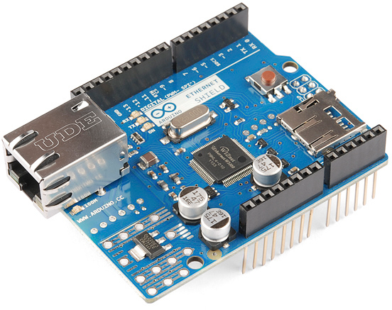
ATmega128RFA1 Iso Shot

This tutorial is focused on documenting the schematic and hardware layout of the development board. It’ll also explain how to program the board via the pre-programmed serial bootloader, from the comfy confines of the Arduino IDE. We’ll finish off the tutorial with some example code, detailing the basics of the ATmega128RFA1’s RF communication capabilities.

ATmega128RFA1 Devlopment Board Features:

  • Arduino R3 Form Factor (Arduino shield compatible)
  • On-Board Chip Antenna
  • 33 Digital I/O’s
    • SPI, TWI (I2C), and UART hardware interfaces
  • 8 Analog Inputs (10-bit resolution)
  • 16 MHz operating frequency
  • ATmegaBOOT bootloader pre-programmed (making it programmable with an FTDI Basic and the Arduino IDE)
  • On-board 3.3V regulator
  • Other standard ATmega128RFA1 features:
    • 6 Timers
    • 128 KB Flash
    • 16 KB SRAM
    • 4096 Bytes EEPROM
    • 2.4 GHz RF Transciever

Required Materials

In this tutorial, we’ll cover the basics of getting the ATmega128RFA1 Development Board up-and-running. There will be a focus on programming the board via the bootloader (in the Arduino IDE), using an FTDI Board. To follow along, you’ll need these materials:


Male headers are useful for soldering into programming headers, while female headers help to add shield compatibility. A pair of ATmega128RFA1s – either the SparkFun board, or another development platform – are required to test communication between the chips.

Required Tools

This assembly will require some simple soldering, so you’ll need a soldering iron and a bit of solder. If you’ve never soldered before, check out our how to solder guide.

Recommended Reading

This tutorial assumes some previous electronics knowledge to get along. If you’re not familiar with these concepts, consider checking out our tutorials on the subject!

  • What is an Arduino - While not directly using an Arduino platform, this tutorial will make use of the IDE.
  • Installing FTDI Drivers - If you’ve never used an FTDI cable or board before, you’ll need to install drivers.
  • Serial Communication - We’ll be using the ATmega128RFA1 boards as wireless bridges between two serial devices.
  • How to Use GitHub - All of the source code and design files are hosted on Github.

About the ATmega128RFA1

The ATmega128RFA1 is a portmanteau of sorts – two separate components combined to form one device. Half microcontroller, half RF transceiver.

ATmega128

Half of the ATmega128RFA1 is an ATmega128, an old mainstay of Atmel AVR microcontrollers. The 128 is an 8-bit microcontroller with 128kB of programmable flash, an abundance of I/O pins, an analog-to-digital converter, and much more.

Low-Power 2.4GHz Transceiver

The other half of the ATmega128RFA1 – the “RFA1” part – is what really makes it unique. That’s because built into the chip is a 2.4GHz wireless radio transceiver. So one ATmega128RFA1 could talk to another up to about 75m away, at speeds of up to 2 Mbps.

Because it has built-in hardware support for IEEE 802.15.4, the chip can also talk to RF modules, like ZigBee’s, Synapse modules, and IPv6/6LoWPAN devices. 802.15.4 defines a personal area network (PAN) of wireless devices. It’s very similar to the Bluetooth standard (802.15.1) in that way. Unlike Bluetooth though, which can send data at around 3Mbps, 802.15.4 can’t achieve as high a data rate, maxing out at around 250kbps. Still, 802.15.4 is an excellent, cost-sensitive choice when you don’t need to quickly send huge chunks of wireless data.

In comparison to the other wireless standards and protocols out there, the ATmega128RFA1’s transceiver is geared towards low-level, low-power, low-speed, low-data rate, low-range communication between devices. This isn’t like WiFi, where we need to stream video, while downloading pictures of cats, and syncing our dropboxes. 802.15.4 is for sending data between embedded devices. Maybe you want to periodically transmit data from a weather station to a display in your house, or turn your coffee machine on from the bed. That’s the type of situation 802.15.4 works best in! That sounds like a job for the ATmega128RFA1 Dev Board!

Schematic and Hardware

The development board surrounds the ATmega128RFA1 with all of the supporting circuitry one might need to get up-and-running with the chip.

ATmega128RFA1 Dev Board Schematic

Click the image to get a bigger view of the schematic. Or you can download a PDF of it.

Power Input

The power input section of the circuit includes a voltage regulator, which feeds 3.3V to the rest of the circuit. The following footprints are provided for power input:

The slide-switch on the side of the board controls the flow of the input power sources above to the regulator.

The 3.3V and GND pins are also broken out along the side of the board. These nets are unregulated, but can be used to supply a clean, regulated 3.3V voltage source to the board.

ATmega128RFA1 Circuitry

The ATmega128RFA1 is supported by a 16MHz crystal and an assortment of decoupling caps. The RF section of the board has a crystal of its own, as well as a chip antenna and circuitry to support the RF interface. Try to avoid placing components near the antenna, as they may interfere with signal strength.

All digital I/O pins of the ATmega128RFA1 are broken out in some form or another. Two on-board LEDs are connected to the MCU’s pins B6 and B7. The remaining I/O’s are broken out to the outer headers of the board. The eight analog inputs on port F are available in the same place you’d expect to find an Arduino’s analog pins. Key digital pins, like the hardware SPI, I2C, and UART pins, are broken out to the same locations found on Arduinos as well.

Programming Headers

There are two programming headers on the board. One 6-pin (2x3) ICSP header, which can be used to program the chip using a standard AVR in-circuit programmer. A 6-pin serial header near the power inputs can also be used to program the chip (assuming the bootloader’s still on there); this header should match up to common FTDI headers and cables (just make sure they’re the 3.3V variety).

Annotated ATmega128RFA1 Dev Board Image

Powering the Board

There are a variety of ways to power the development board. Input jacks are broken out for barrel jack, JST, screw, and 0.1" connectors. Whichever voltage supply you choose to power the board, it should be between 4.5 and 15V. Each of these power sources is fed into the voltage regulator, which drops the voltage down to 3.3V.

If you’re using the barrel jack, a 5V or 9V wall-wart is a good choice for power source.

Voltage can be fed directly to the chip, using the headers labeled “3.3V” – just make sure the voltage doesn’t exceed 3.6V. The ATmega128RFA1 can only operate at voltages between 1.8 and 3.6V.

One of the ATmega128RFA1’s key features is its low power consumption. Sending or receiving RF data should only require 16 to 18mA of current. Idling, the chip should only require about 1-4.5mA. Each of the output pins can source/sink between 2-8mA.

Check out the datasheet for more electrical specs.

How To Program

Below, we’ll explain the two interfaces available for programming the ATmega128RFA1. There is a serial bootloader pre-programmed onto the board, or you can use the standard AVR 6-pin ISP header. In either case, you’ll probably need to solder headers onto the programming port pins to connect a programmer.

ATmegaBOOT Serial Bootloader

Bootloaders are small programs loaded onto a chip, which make uploading compiled code easier. Instead of requiring a specialized (often expensive) piece of hardware – a programmer – a more generalized tool can be used to upload to the board.

The ATmega128RFA1 Development Board ships with a pre-programmed serial bootloader. Either an (archaic) serial port can be used to upload code to the board, or a more common USB-to-Serial converter can be used. We recommend the 3.3V FTDI Basic board, which interfaces directly to the 6-pin serial header of the dev board.

FTDI Basic Programming (and powering) the board

A 3.3V FTDI Basic Board connected to the development board’s serial programming header. Right-angle headers were previously soldered to the header. As a bonus, the FTDI basic can also power the dev board.

The bootloader on the ATmega128RFA1 Dev Board is a variation of the ATmegaBOOT serial bootloader, which was used on older Arduinos like the Duemilanove. This bootloader uses the UART0 of the ATmega128RFA1, and expects uploaded code at a baud rate of 57600.

If you’re familiar with avrdude, a command like the one below should upload a compiled piece of code.

avrdude -p atmega128rfa1 -c arduino -P \\.\COM## -b 57600 -D -V -U flash:w:test-sketch.hex:i

Or, skip avrdude, and use the Arduino IDE with the bootloader, as we’ll explain in the following pages.

ISP Programmer

If you’ve got an AVR programmer and would rather skip working with the bootloader, the standard AVR 2x3 pin programming header is broken out on the board. Pin 1 of the programming port is marked with a silk-screened dash.

AVR Pocket Programmer programming the dev board

An AVR Pocket Programmer connected to the development board’s ISP header. Straight headers were previously soldered to the header to allow for the connection.

If you don’t have an AVR programmer but would still prefer using this method for uploading code, we’d recommend the USB Pocket AVR Programmer. Using that, an avrdude command like below can be used to upload a program:

avrdude -p atmega128rfa1 -c usbtiny -P usb -D -V -U flash:w:test-sketch.hex:i

If you have an Arduino, that can work as an alternative to the AVR programmer – check out the the ArduinoISP sketch under the examples menu.

Arduino Compatibility

Everyone loves Arduino! The simplified IDE and host of libraries and supporting code make it an awesome place to start prototyping. The ATmega128RFA1 shares a lot in common with the popular ATmega328 used on the Arduino Uno, so it seems reasonable that we should be able to program the board using the Arduino software. There are just a few extra steps which need to be taken to do so.

First, if you haven’t already, download and install Arduino. Then…

Update WinAVR (For Windows Users)

WinAVR is a wonderful, free, and open-source package of AVR utilities (including avr-gcc and avrdude) and definition files. It forms the backbone of most AVR development, including any AVR-based Arduino. Unfortunately, Arduino is (as of v1.0.5) packaged with an out-of-date version of WinAVR, which does not support the ATmega128RFA1. But it’s easy to upgrade!

Download the most recent version of WinAVR (WinAVR-20100110 as of writing this) from the WinAVR project page. It should be installed over the old version of WinAVR included with Arduino, which is located in the Arduino\hardware\tools\avr directory. Follow these steps to update WinAVR:

  1. Run the WinAVR installer (WinAVR-20100110-install.exe).
  2. Cick "Run", Select your install Language, Click "Next", Click "I Agree" (unless you don't?), until you get to the install location screen.
  3. On the install location screen, click Browse..., and navigate to the ../hardware/tools/avr directory inside your Arduino install (with the Arduino installer, it should go to the location seen in this image):

  4. Click next. On the next screen, make sure Install files and Add Directories to PATH are selected. Install Programmers Notepad is optional.

  5. Click Install and wait for the install to finish.

Alternative to that method, you can install WinAVR to a standalone directory, and copy/paste it into the Arduino directory.

Add the Board Definitions File

We also need to add a board definition file to be able to use the ATmega128RFA1 Dev Board within the Arduino environment. To begin, download the ATmega128RFA1 arduino addon.

The 128RFA1-DEV folder from that download should be added to a hardware directory within your Arduino sketchbook. Normally the sketchbook will install to your documents/Arduino folder. If a hardware folder isn’t already there, make it.

Boards.txt selection in Windows 7

This directory contains a boards.txt file which defines the ATmega128RFA1 Dev Board, and adds a selectable option under the Tools > Board menu. When you open the Arduino IDE (close and reopen it if it’s already open), this option should be added to the menu:

Arduino Board Selection

With that selected, you’re ready to upload some code to the board!

Pin Mapping

After you’ve added ATmega128RFA1-compatibility to your Arduino IDE, you can take advantage of all of the wonderful libraries you may have grown acustomed to, including Serial, SPI, and Wire. In addition to that each pin is mapped to a unique pin number, which you can invoke all of your digitalWrite, digitalRead, analogWrite, and analogRead needs upon.

The addon defines all of the ATmega128RFA1’s pins as singular numbers. Just as Arduino has pins 0-13, and A0-A6, this development board has pins 0-25, and A0-A7. Here’s how the pins are mapped out:

ATmega128RFA1 Pin-out

There are a few pins with PWM functionality– 3, 4, 5, 8, 9, 19, 34, and 35 – which you can use for analogWrite. Note that pins 34 and 35 are not broken out to pins. They’re only connected to on-board LEDs.

The SPI, UART, and I2C pins are where you’d expect them to be on an equivalent R3-or-later Arduino Uno. There is a second UART – UART1 – on pins D2 and D3.

Example Code

Example Sketch: RF Chat

You can download the RF chat example here (or grab it from github). This is a simple example of how to make use of the RF functionality of the ATmega128RFA1. The radio-specific functions are split off into a secondary file – RadioFunctions.h.

You’ll need two ATmega128RFA1’s for this example (it’s hard to demo the RF functionality without something to talk to!). They can be tied to the same computer, or a few rooms away. The maximum distance should be around 75m, but that’s with complete line-of-sight, walls will diminish the range.

Upload the same sketch to each dev board. Then open up a serial monitor on each. You can use either the Arduino Serial Monitor, or a stand-alone terminal program (Tera Term is great for Windows users, Cool Term should work for Mac). Open up each serial port to 9600 bps (8 data bits, no parity, 1 stop bit), and start typing away! What’s typed into one terminal should pop up into another.

Serial chat example

Understanding the Sketch

There are a few key functions, and a few interrupt routines that are key to the workings of the RF transceiver.

rfBegin()

First, the radio must be initialized by calling the rfBegin() function. This is called in the setup() portion of the sketch. Check out the comments within the code for a line-by-line explanation. This function initializes the ATmega128RFA1’s radio. The lone parameter for this function sets the radio’s 2.4GHz channel, which should be some value between 11 and 26. Radios must be on the same channel to communicate with each other.

language:c
// Initialize the RFA1's low-power 2.4GHz transciever.
// Sets up the state machine, and gets the radio into
// the RX_ON state. Interrupts are enabled for RX
// begin and end, as well as TX end.
uint8_t rfBegin(uint8_t channel)
{
  for (int i=0; i<128; i++)
  {
    radioRXBuffer.buffer[i] = 0;
  }
  radioRXBuffer.tail = 0;
  radioRXBuffer.head = 0;

  // Setup RX/TX LEDs: These are pins B6/34 (RX) and B7/35 (TX).
  pinMode(RX_LED, OUTPUT);
  digitalWrite(RX_LED, LOW);
  pinMode(TX_LED, OUTPUT);
  digitalWrite(TX_LED, LOW);

  // Transceiver Pin Register -- TRXPR.
  // This register can be used to reset the transceiver, without
  // resetting the MCU.
  TRXPR |= (1<<TRXRST);   // TRXRST = 1 (Reset state, resets all registers)

  // Transceiver Interrupt Enable Mask - IRQ_MASK
  // This register disables/enables individual radio interrupts.
  // First, we'll disable IRQ and clear any pending IRQ's
  IRQ_MASK = 0;  // Disable all IRQs

  // Transceiver State Control Register -- TRX_STATE
  // This regiseter controls the states of the radio.
  // First, we'll set it to the TRX_OFF state.
  TRX_STATE = (TRX_STATE & 0xE0) | TRX_OFF;  // Set to TRX_OFF state
  delay(1);

  // Transceiver Status Register -- TRX_STATUS
  // This read-only register contains the present state of the radio transceiver.
  // After telling it to go to the TRX_OFF state, we'll make sure it's actually
  // there.
  if ((TRX_STATUS & 0x1F) != TRX_OFF) // Check to make sure state is correct
    return 0;    // Error, TRX isn't off

  // Transceiver Control Register 1 - TRX_CTRL_1
  // We'll use this register to turn on automatic CRC calculations.
  TRX_CTRL_1 |= (1<<TX_AUTO_CRC_ON);  // Enable automatic CRC calc.

  // Enable RX start/end and TX end interrupts
  IRQ_MASK = (1<<RX_START_EN) | (1<<RX_END_EN) | (1<<TX_END_EN);

  // Transceiver Clear Channel Assessment (CCA) -- PHY_CC_CCA
  // This register is used to set the channel. CCA_MODE should default
  // to Energy Above Threshold Mode.
  // Channel should be between 11 and 26 (2405 MHz to 2480 MHz)
  if ((channel < 11) || (channel > 26)) channel = 11;
  PHY_CC_CCA = (PHY_CC_CCA & 0xE0) | 11; // Set the channel to 11

  // Finally, we'll enter into the RX_ON state. Now waiting for radio RX's, unless
  // we go into a transmitting state.
  TRX_STATE = (TRX_STATE & 0xE0) | RX_ON; // Default to receiver

  return 1;
}

rfWrite(uint8_t b) and rfPrint(String toPrint)

These two functions are your go-to routines for sending data out of the radio. There’s one function to write a single byte at a time and another to send a whole string (up to 127 characters) at once.

In the main sketch, rfPrint() is called at the very beginning to shout out to other 128RFA1 devices that the board has booted up. rfWrite() is called whenever the board sees serial data come in.

language:c
// This function sends a string of characters out of the radio.
// Given a string, it'll format a frame, and send it out.
void rfPrint(String toPrint)
{
  uint8_t frame[127];  // We'll need to turn the string into an arry
  int length = toPrint.length();  // Get the length of the string
  for (int i=0; i<length; i++)  // Fill our array with bytes in the string
  {
    frame[i] = toPrint.charAt(i);
  }

  // Transceiver State Control Register -- TRX_STATE
  // This regiseter controls the states of the radio.
  // Set to the PLL_ON state - this state begins the TX.
  TRX_STATE = (TRX_STATE & 0xE0) | PLL_ON;  // Set to TX start state
  while(!(TRX_STATUS & PLL_ON))
    ;  // Wait for PLL to lock

  digitalWrite(TX_LED, HIGH);

  // Start of frame buffer - TRXFBST
  // This is the first byte of the 128 byte frame. It should contain
  // the length of the transmission.
  TRXFBST = length + 2;
  memcpy((void *)(&TRXFBST+1), frame, length);
  // Transceiver Pin Register -- TRXPR.
  // From the PLL_ON state, setting SLPTR high will initiate the TX.
  TRXPR |= (1<<SLPTR);   // SLPTR high
  TRXPR &= ~(1<<SLPTR);  // SLPTR low

  // After sending the byte, set the radio back into the RX waiting state.
  TRX_STATE = (TRX_STATE & 0xE0) | RX_ON;
}

// This function will transmit a single byte out of the radio.
void rfWrite(uint8_t b)
{
  uint8_t length = 3;

  // Transceiver State Control Register -- TRX_STATE
  // This regiseter controls the states of the radio.
  // Set to the PLL_ON state - this state begins the TX.
  TRX_STATE = (TRX_STATE & 0xE0) | PLL_ON;  // Set to TX start state
  while(!(TRX_STATUS & PLL_ON))
    ;  // Wait for PLL to lock

  digitalWrite(TX_LED, HIGH);  // Turn on TX LED

  // Start of frame buffer - TRXFBST
  // This is the first byte of the 128 byte frame. It should contain
  // the length of the transmission.
  TRXFBST = length;
  // Now copy the byte-to-send into the address directly after TRXFBST.
  memcpy((void *)(&TRXFBST+1), &b, 1);

  // Transceiver Pin Register -- TRXPR.
  // From the PLL_ON state, setting SLPTR high will initiate the TX.
  TRXPR |= (1<<SLPTR);   // SLPTR = 1
  TRXPR &= ~(1<<SLPTR);  // SLPTR = 0  // Then bring it back low

  // After sending the byte, set the radio back into the RX waiting state.
  TRX_STATE = (TRX_STATE & 0xE0) | RX_ON;
}

rfAvailable() and rfRead()

These functions operate in a manner similar to the Arduino Serial library, if you’re familiar with that. Data coming into the radio is stored in a buffer It’s up to you to empty that buffer. rfAvailable() returns a number explaining how many bytes of data are still un-read in the buffer. It can be 0, meaning the buffer is empty.

rfRead() returns a single byte from the front of the receive buffer. In the main sketch loop, we continuously check if RF data is available. If there is data, we use rfRead() to collect it and print it out to the serial monitor.

language:c
// Returns how many unread bytes remain in the radio RX buffer.
// 0 means the buffer is empty. Maxes out at RF_BUFFER_SIZE.
unsigned int rfAvailable()
{
  return (unsigned int)(RF_BUFFER_SIZE + radioRXBuffer.head - radioRXBuffer.tail) % RF_BUFFER_SIZE;
}

// This function reads the oldest data in the radio RX buffer.
// If the buffer is emtpy, it'll return a 255.
char rfRead()
{
  if (radioRXBuffer.head == radioRXBuffer.tail)
  {
    return -1;
  }
  else
  {
    // Read from the buffer tail, and update the tail pointer.
    char c = radioRXBuffer.buffer[radioRXBuffer.tail];
    radioRXBuffer.tail = (unsigned int)(radioRXBuffer.tail + 1) % RF_BUFFER_SIZE;
    return c;
  }
}

Interrupt Routines

Three interrupt routines are working behind the scenes, whenever there is a radio receive or transmit. Two simple interrupt service routines (ISRs) – the transmit end, and receieve start – trigger the RX/TX LEDs. The receive end ISR does a lot of heavy-lifting, on the other hand. It accesses the radio’s received data registers and stores the data into the shard receive buffer. None of these functions can be called manually. They all just do their job whenever called upon by the processor.

language:c
// This interrupt is called when radio TX is complete. We'll just
// use it to turn off our TX LED.
ISR(TRX24_TX_END_vect)
{
  digitalWrite(TX_LED, LOW);
}

// This interrupt is called the moment data is received by the radio.
// We'll use it to gather information about RSSI -- signal strength --
// and we'll turn on the RX LED.
ISR(TRX24_RX_START_vect)
{
  digitalWrite(RX_LED, HIGH);  // Turn receive LED on
  rssiRaw = PHY_RSSI;  // Read in the received signal strength
}

// This interrupt is called at the end of data receipt. Here we'll gather
// up the data received. And store it into a global variable. We'll
// also turn off the RX LED.
ISR(TRX24_RX_END_vect)
{
  uint8_t length;
  // Maximum transmission is 128 bytes
  uint8_t tempFrame[RF_BUFFER_SIZE];

  // The received signal must be above a certain threshold.
  if (rssiRaw & RX_CRC_VALID)
  {
    // The length of the message will be the first byte received.
    length = TST_RX_LENGTH;
    // The remaining bytes will be our received data.
    memcpy(&tempFrame[0], (void*)&TRXFBST, length);

    // Now we need to collect the frame into our receive buffer.
    //  k will be used to make sure we don't go above the length
    //  i will make sure we don't overflow our buffer.
    unsigned int k = 0;
    unsigned int i = (radioRXBuffer.head + 1) % RF_BUFFER_SIZE; // Read buffer head pos and increment;
    while ((i != radioRXBuffer.tail) && (k < length-2))
    {
      // First, we update the buffer with the first byte in the frame
      radioRXBuffer.buffer[radioRXBuffer.head] = tempFrame[k++];
      radioRXBuffer.head = i; // Update the head
      i = (i + 1) % RF_BUFFER_SIZE; // Increment i % BUFFER_SIZE
    }
  }

  digitalWrite(RX_LED, LOW);  // Turn receive LED off, and we're out
}

Those functions should serve as a backbone for all of your radio needs. Instead of setting up a chat server, you could set one outside to monitor weather conditions and relay that back to a display indoors. Or set up one under your mattress, with pressure sensors strategically connected, while another dev board connected to your coffee machine could wait for a signal to start brewing a cup. These are neat little boards, we’d love to hear about what applications you’ve come up with!

Resources

All of the example code, hardware layout, and Arduino addon files can be found on this project’s github repo. Other resources include:

The example in this tutorial is as basic as it gets; the ATmega128RFA1 has a powerful transceiver, which can even be synced up to 802.15.4 networks (like Zigbee). Here are some other resources out there, if you’re looking for something more robust:

  • Lightweight Mesh - A (proprietary) Atmel Lightweight Mesh software stack.
  • IEEE 802.15.4 MAC - Another Atmel-provided software stack. This one implements IEEE 802.15.4.
  • BitCloud ZigBee Pro - If you’re looking to make your ATmega128RFA1 communicate with ZigBee PROs, BitCloud is the software you’ll need to do it. This link includes documentation and source code downloads.
  • Synapse Wireless - Synapse is a nifty wireless platform, because each of the wireless modules run a python scrip and interpreter. That, along with self-healing-mesh clouds and remote procedure calls, makes Synapse totally awesome. The ATmega128RFA1 Development Board is Synapse-compatible, you can upload a Synapse hex file to it, and it’ll work just like an RF200. Licenses for the Synapse software aren’t free, so keep that in mind.
  • ZigDuino - A really well done Arduino plug-in for the ATmega128RFA1. We’re big fans.

Going Further

Now that you know how to hook up the ATmega128RFA1 Development Board, what components will you be adding with the RF transceiver to help make wireless? Need some inspiration? Check out some of these products and tutorials:

  • Synapse Modules - The Synapse RF266 in particular is based on the ATmega128RFA1. These are nifty little wireless modules, which can interpret python scripts. Check out our tutorial for working with them as well.
  • XBee Modules - With the right firmware (ZigBee), an ATmega128RFA1 could be made to communicate with these modules.

Or check out some of these tutorials:

  • IR Communication - If you’re only really looking to transmit data short, wireless distances, infrared may be a better/cheaper option.
  • Using the OpenSegment - The OpenSegment displays are really easy-to-use 4-digit 7-segment displays. You could use one of these displays to print messages received from other ATmega128RFA1 nodes.

Or, check out our how to use GitHub tutorial, and help us make the ATmega128RFA1 example code better by adding new features!


learn.sparkfun.com |CC BY-SA 3.0 | SparkFun Electronics | Boulder, Colorado

Light-emitting Diodes (LEDs)

$
0
0

Light-emitting Diodes (LEDs) a learn.sparkfun.com tutorial

The Basics

alt text

LEDs are all around us: In our phones, our cars and even our homes. Any time something electronic lights up, there’s a good chance that an LED is behind it. They come in a huge variety of sizes, shapes, and colors, but no matter what they look like they have one thing in common: they’re the bacon of electronics. They’re widely purported to make any project better and they’re often added to unlikely things (to everyone’s delight).

Unlike bacon, however, they’re no good once you’ve cooked them. This guide will help you avoid any accidental LED barbecues! First things first, though. What exactly is this LED thing everyone’s talking about?

LEDs (that’s “ell-ee-dees”) are a particular type of diode that convert electrical energy into light. In fact, LED stands for “Light Emitting Diode.” (It does what it says on the tin!) And this is reflected in the similarity between the diode and LED schematic symbols:

alt text

In short, LEDs are like tiny lightbulbs. However, LEDs require a lot less power to light up by comparison. They’re also more energy efficient, so they don’t tend to get hot like conventional lightbulbs do (unless you’re really pumping power into them). This makes them ideal for mobile devices and other low-power applications. Don’t count them out of the high-power game, though. High-intensity LEDs have found their way into accent lighting, spotlights and even automotive headlights!

Are you getting the craving yet? The craving to put LEDs on everything? Good, stick with us and we’ll show you how!

Suggested Reading

Here are some other topics that will be discussed in this tutorial. If you are unfamiliar with any of them, please have a look at the respective tutorial before you go any further.

How to Use Them

alt text

So you’ve come to the sensible conclusion that you need to put LEDs on everything. We thought you’d come around. Let’s go over the rule book:

1) Polarity Matters

In electronics, polarity indicates whether a circuit component is symmetric or not. LEDs, being diodes, will only allow current to flow in one direction. And when there’s no current-flow, there’s no light. Luckily, this also means that you can’t break an LED by plugging it in backwards. Rather, it just won’t work.

alt text

The positive side of the LED is called the “anode” and is marked by having a longer “lead,” or leg. The other, negative side of the LED is called the “cathode.” Current flows from the anode to the cathode and never the opposite direction. A reversed LED can keep an entire circuit from operating properly by blocking current flow. So don’t freak out if adding an LED breaks your circuit. Try flipping it around.

2) Moar Current Equals Moar Light

The brightness of an LED is directly dependent on how much current it draws. That means two things. The first being that super bright LEDs drain batteries more quickly, because the extra brightness comes from the extra power being used. The second is that you can control the brightness of an LED by controlling the amount of current across it. But, setting the mood isn’t the only reason to cut back your current.

3) There is Such a Thing as Too Much Power

If you connect an LED directly to a current source it will try to dissipate as much power as it’s allowed to draw, and, like the tragic heroes of olde, it will destroy itself. That’s why it’s important to limit the amount of current flowing across the LED.

For this, we employ resistors. Resistors limit the flow of electrons in the circuit and protect the LED from trying to draw too much current. Don’t worry, it only takes a little basic math to determine the best resistor value to use. You can find out all about it in our resistor tutorial!

Don’t let all of this math scare you, it’s actually pretty hard to mess things up too badly. In the next section, we’ll go over how to make an LED circuit without getting your calculator.

LEDs Without Math

Before we talk about how to read a datasheet, let’s hook up some LEDs. After all, this is an LED tutorial, not a reading tutorial.

It’s also not a math tutorial, so we’ll give you a few rules of thumb for getting LEDs up and running. As you’ve probably put together from the info in the last section, you’ll need a battery, a resistor and an LED. We’re using a battery as our power source, because they’re easy to find and they can’t supply a dangerous amount of current.

The basic template for an LED circuit is pretty simple, just connect your battery, resistor and LED in series. Like this:


alt text


A good resistor value for most LEDs is 330 Ohms. You can use the information from the last section to help you determine the exact value you need, but this is LEDs without math… So, start by popping a 330 Ohm resistor into the above circuit and see what happens.

The interesting thing about resistors is that they’ll dissipate extra power as heat, so if you have a resistor that’s getting warm, you probably need to go with a smaller resistance. If your resistor is too small, however, you run the risk of burning out the LED! Given that you have a handful of LEDs and resistors to play with, here’s a flow chart to help you design your LED circuit by trial and error:


alt text


Another way to light up an LED is to just connect it to a coin cell battery! Since the coin cell can’t source enough current to damage the LED, you can connect them directly together! Just push a CR2032 coin cell between the leads of the LED. The long leg of the LED should be touching the side of the battery marked with a “+”. Now you can wrap some tape around the whole thing, add a magnet, and stick it to stuff! Yay for throwies!

alt text

Of course, if you’re not getting great results with the trial and error approach, you can always get out your calculator and math it up. Don’t worry, it’s not hard to calculate the best resistor value for your circuit. But before you can figure out the optimal resistor value, you’ll need to find the optimal current for your LED. For that we’ll need to report to the datasheet…

Get the Details

Don’t go plugging any strange LEDs into your circuits, that’s just not healthy. Get to know them first. And how better than to read the datasheet.

As an example we’ll peruse the datasheet for our Basic Red 5mm LED.

LED Current

Starting at the top and making our way down, the first thing we encounter is this charming table:

alt text

Ah, yes, but what does it all mean?

The first row in the table indicates how much current your LED will be able to handle continuously. In this case, you can give it 20mA or less, and it will shine its brightest at 20mA. The second row tells us what the maximum peak current should be for short bursts. This LED can handle short bumps to 30mA, but you don’t want to sustain that current for too long. This datasheet is even helpful enough to suggest a stable current range (in the third row from the top) of 16-18mA. That’s a good target number to help you make the resistor calculations we talked about.

The following few rows are of less importance for the purposes of this tutorial. The reverse voltage is a diode property that you shouldn’t have to worry about in most cases. The power dissipation is the amount of power in milliWatts that the LED can use before taking damage. This should work itself out as long as you keep the LED within its suggested voltage and current ratings.

LED Voltage

Let’s see what other kinds of tables they’ve put in here… Ah!

alt text

This is a useful little table! The first row tells us what the forward voltage drop across the LED will be. Forward voltage is a term that will come up a lot when working with LEDs. This number will help you decide how much voltage your circuit will need to supply to the LED. If you have more than one LED connected to a single power source, these numbers are really important because the forward voltage of all of the LEDs added together can’t exceed the supply voltage. We’ll talk about this more in-depth later in the delving deeper section of this tutorial.

LED Wavelength

The second row on this table tells us the wavelength of the light. Wavelength is basically a very precise way of explaining what color the light is. There may be some variation in this number so the table gives us a minimum and a maximum. In this case it’s 620 to 625nm, which is just at the lower red end of the spectrum (620 to 750nm). Again, we’ll go over wavelength in more detail in the delving deeper section.

LED Brightness

The last row (labeled “Luminous Intensity”) is a measure of how bright the LED can get. The unit mcd, or millicandela, is a standard unit for measuring the intensity of a light source. This LED has an maximum intensity of 200 mcd, which means it’s just bright enough to get your attention but not quite flashlight bright. At 200 mcd, this LED would make a good indicator.

Viewing Angle

alt text

Next, we’ve got this fan-shaped graph that represents the viewing angle of the LED. Different styles of LEDs will incorporate lenses and reflectors to either concentrate most of the light in one place or spread it as widely as possible. Some LEDs are like floodlights that pump out photons in every direction; Others are so directional that you can’t tell they’re on unless you’re looking straight at them. To read the graph, imagine the LED is standing upright underneath it. The “spokes” on the graph represent the viewing angle. The circular lines represent the intensity by percent of maximum intensity. This LED has a pretty tight viewing angle. You can see that looking straight down at the LED is when it’s at its brightest, because at 0 degrees the blue lines intersect with the outermost circle. To get the 50% viewing angle, the angle at which the light is half as intense, follow the 50% circle around the graph until it intersects the blue line, then follow the nearest spoke out to read the angle. For this LED, the 50% viewing angle is about 20 degrees.

Dimensions

alt text

Finally, the mechanical drawing. This picture contains all of the measurements you’ll need to actually mount the LED in an enclosure! Notice that, like most LEDs, this one has a small flange at the bottom. That comes in handy when you want to mount it in a panel. Simply drill a hole the perfect size for the body of the LED, and the flange will keep it from falling through!

Now that you know how to decipher the datasheet, let’s see what kind of fancy LEDs you might encounter in the wild…

Types of LEDs

Congratulations, you know the basics! Maybe you’ve even gotten your hands on a few LEDs and started lighting stuff up, that’s awesome! How would you like to step up your blinky game? Let’s talk about makin' it fancy.

Here’s the cast of characters:

alt text

RGB (Red-Green-Blue) LEDs are actually three LEDs in one! But that doesn’t mean it can only make three colors. Because red, green, and blue are the additive primary colors, you can control the intensity of each to create every color of the rainbow. Most RGB LEDs have four pins: one for each color and a common pin. On some, the common pin is the anode, and on others, it’s the cathode.


alt text

Some LEDs are smarter than others. Take the flashing LED, for example. Inside these LEDs, there’s actually an integrated circuit that allows the LED to blink without any outside controller. Simply power it up and watch it go! These are great for projects where you want a little bit more action but don’t have room for control circuitry. There are even RGB flashing LEDs that cycle through thousands of colors!


alt text

SMD LEDs aren’t so much a specific kind of LED but a package type. As electronics get smaller and smaller, manufacturers have figured out how to cram more components in a smaller space. SMD (Surface Mount Device) parts are tiny versions of their standard counterparts. SMD LEDs come in several sizes, from fairly large to smaller than a grain of rice! Because they’re so small, and have pads instead of legs, they’re not as easy to work with, but if you’re tight on space they might be just what the doctor ordered.


alt text

High-Power LEDs, from manufacturers like Luxeon and CREE, are crazy bright. Generally, an LED is considered High-Power if it can dissipate 1 Watt or more of power. These are the fancy LEDs that you find in really nice flashlights. Arrays of them can even be built for spotlights and automobile headlights. Because there’s so much power being pumped through the LED, these often require heatsinks. A heatsink is basically a chunk of heat conducting metal with lots of surface area whose job is to transfer as much waste heat into the surrounding air as possible. High-Power LEDs can generate so much waste heat that they’ll damage themselves without proper cooling. Don’t let the term “waste heat” fool you, though, these devices are still incredibly efficient compared to conventional bulbs.


alt text

There are even LEDs that emit light outside of the normal visible spectrum. You probably use Infrared LEDs every day, for instance. They’re used in things like TV remotes to send small pieces of information in the form of invisible light! On the opposite end of the spectrum you can also get Ultraviolet LEDs. Ultraviolet LEDs will make certain materials floresce, just like a blacklight! They’re also used for disinfecting surfaces, because many bacteria are sensitive to UV radiation.


With fancy LEDs like these at your disposal, there’s no excuse for leaving anything un-illuminated. However, if your thirst for LED knowledge hasn’t been slaked, then read on, and we’ll get into the nitty-gritty on LEDs, color, and luminous intensity!

Delving Deeper

So you’ve graduated from LEDs 101 and you want more? Oh, don’t worry, we’ve got more. Let’s start with the science behind what makes LEDs tick… err… blink. We’ve already mentioned that LEDs are a special kind of diode, but let’s delve a little deeper into exactly what that means:

What we call an LED is really the LED and the packaging together, but the LED itself is actually tiny! It’s a chip of semiconductor material that’s doped with impurities which creates a boundary for charge carriers. When current flows into the semi-conductor, it jumps from one side of this boundary to the other, releasing energy in the process. In most diodes that energy leaves as heat, but in LEDs that energy is dissipated as light!

The wavelength of light, and therefore the color, depends on the type of semiconductor material used to make the diode. That’s because the energy band structure of semiconductors differs between materials, so photons are emitted with differing frequencies. Here’s a table of common LED semiconductors by frequency:

alt text

Truncated table of semiconductor materials by color. The full table is available on the Wikipedia entry for “LED”

While the wavelength of the light depends on the band gap of the semiconductor, the intensity depends on the amount of power being pushed through the diode. We talked about luminous intensity a little bit in a previous section, but there’s more to it than just putting a number on how bright something looks.

The unit for measuring luminous intensity is called the candela, although when you’re talking about the intensity of a single LED you’re usually in the millicandela range. The interesting thing about this unit is that it isn’t really a measure of the amount of light energy, but an actual measure of “brightness”. This is achieved by taking the power emitted in a particular direction and weighting that number by the luminosity function of the light. The human eye is more sensitive to some wavelengths of light than others, and the luminosity function is a standardized model that accounts for that sensitivity.

The luminous intesity of LEDs can range from the tens to the tens-of-thousands of millicandela. The power light on your TV is probably about 100 mcd, whereas a good flashlight might be 20,000 mcd. Looking straight into anything brighter than a few thousand millicandela can be painful; don’t try it.

Going Further

You’ve made it! You know, like, almost everything… about LEDs. Now go forth and put LEDs on whatever you please!

If you’d like to learn more about some LED related topics, visit these other tutorials:


And now… a dramatic reenactment of an LED being over powered and burning itself out:


alt text


Yeah… it’s not spectacular.


learn.sparkfun.com |CC BY-SA 3.0 | SparkFun Electronics | Boulder, Colorado


Dungeons and Dragons Dice Gauntlet

$
0
0

Dungeons and Dragons Dice Gauntlet a learn.sparkfun.com tutorial

Introduction

The D&D bracer is a fairly quick, fun, nerdy LilyPad project. The final product is a wearable bracer with a display that will randomly generate numbers between 1 and 4, 6, 8, 10, 12, 20, or 100 in response to arm movement, so it can effectively replace all of the dice in your bag for a D&D session. It can also serve as a decorative costume piece to get you in character!

D&D Bracer Finished Product

This is an intermediate LilyPad tutorial. You can expect to do a fair amount of sewing, moderate crafting, and you’ll need to be able to upload code to a LilyPad arduino board. You don’t have to write the code, it’s been supplied for you. However, if you want to practice or play around with it, there’s room to customize. This circuit and code were adapted for wearables from a similar project by the awesome John Trepke, one of our tech support geniusaints (I just made that word up, but I like it!)

Materials

This tutorial requires a mix of both electronic items and crafting supplies. Here’s a fancy wishlist of the electronics:


For the display, I used yellow, but you can swap that out for red, green, blue, or white. The 1000mAh battery was what I had on my desk, there’s no reason you can’t use a smaller one if you’d like to conserve space.

On top of that, you’ll also need some crafting supplies from your local craft store:

  • Outer bracer material – This can be leather, pleather, or any stiff material you’d like
  • Inner bracer material – I recommend felt- it doesn’t fray, it holds stitches very well, and it insulates nicely.
  • 10 Grommets
  • Lacing – leather thong, ribbon, whatever will lace the bracer up firmly and look right with your design
  • Trim, embellishments, whatever you’d like to give the bracer some character

Foundational Tutorials

This project tutorial builds on a few more conceptual tutorials. If you’re not familiar with the subjects below, consider reading through those tutorials first:

  • E-Textile Basics– This tutorial should familiarize you with e-textiles and the LilyPad brand of products. If this is your first e-textile project, consider checking out our Firefly Jar project too.
  • How to Sew with Conductive Thread– This a BIGGIE! It goes over the do’s and don'ts of sewing with conductive thread.
  • How to Use a Multimeter– A multimeter will come in handy if you need to troubleshoot your gauntlet circuit.
  • What is an Arduino– The LilyPad Arduino is the brains of our project. Listening to the switch and accelerometer inputs, and controlling the display. If you’re not familiar with Arduino, definitely check out this tutorial.
  • Serial 7-Segment Display Hookup Guide– This is the display we’ll use to show our dice roll. If you’re curious how the display works, check out this tutorial.
  • Accelerometer Basics– We’ll use an accelerometer to sense when you shake your arm. If you’re curious about how accelerometers work, check out this tutorial!
  • Switch Basics– Switches are used to tell our gauntlet which type of dice we want to roll.
  • Battery Technologies– The gauntlet will be powered by a Lithium Polymer (LiPo) battery.

Assembly: Preparation

Our gauntlet circuit is going to look a little something like this:

D&D gauntlet circuit

One of our switches controls current flow out of the battery, the other seven switches are connected to the LilyPad Arduino pins 5-11. The Y-axis of the accelerometer connects to “A1” of the LilyPad, and the “RX” pin of the display connects to “1” (“tx”) of the LilyPad. The rest of our connections are just power and ground.

Bracer Preparation

Start with your bracer pattern. You can be as simple or as complicated about this as you’d like. There are a number of bracer patterns online, or you can create a basic trapezoid shape. Use the circumference of your wrist for the short side, the circumference of your forearm for the long side, and the length you’d like the bracer to be for the equilateral sides. Mine was about 9 inches long. If yours is shorter, you might have to condense my circuit a little bit to make it fit. You’ll cut your leather to this size and shape, but let’s start with the felt so that we can create the circuit. Cut the felt one inch smaller than the pattern on all sides, and lay out your circuit. It should look roughly like this:

Circuit layout

Make sure that you have the LilyPad Arduino Main Board oriented properly. You want to be able to attach everything properly. The 7-segment display will need to be flush with the fabric, so start by tracing around the face of the display on the fabric and then cutting this rectangle out.

Cutting slot for display

The side of the fabric you’ve laid the parts out on will be the back of the bracer. Press the display through the hole in the back to the front, like so.

Sticking display through

Now that the display is lying flush with the felt, so that only the red PCB is on the back side, it’s time to begin sewing!

Assembly: Sewing Ground

I’ve traced out the first connections you’ll sew here in copper tape. I’m going to start with all of the negative traces. You’ll be connecting all of the main components to each other and to ground on your power supply. Remove all of the switches on the right-hand side, leaving only the one next to the power supply, which is your LiPo Charger Basic.

Ground trace layout

Take a look at these connections. What you are doing is connecting every pin that is labeled either (-) or GND to each other, and then to one side of the power switch. Then connect the other side of the switch to the (-) pin on the power supply. This way, when you toggle this switch, you are creating and breaking the connection between the entire circuit and the power supply. This will be your on/off switch for the whole bracer. One trace goes off to the right side because we will be attaching it to the remaining 7 switches.

Overview of GND trace

Here is a photo of my completed stitching on the negative trace. Feel free to skip to the end and see what all of the finished stitching looks like if you’d like to make changes the the circuit. As long as you leave room for all of the traces you see there, everything should be fine. You can move components into a configuration that works better for you or better fits the shape you have chosen for your bracer.

Adding the switches

The next step will be adding the remaining switches. Line them up against the edge of the fabric. I tried to keep mine roughly equidistant. You can arrange them however you’d like, so long as you’ll be able to connect one to each of the arduino pins 5-11. Mark where each button will go on the front and back side.

Marking switch placement

Tie your thread onto the long end you sewed from the negative circuit, and sew a line up the left side of the felt. Using the marks you made, move the button to the top side of the fabric, and sew down the ‘Off’ side until you have a line of all 7 of these switches sewn to each other and to the negative connections.

GND trace completed

Tie off your thread, and start fresh for the next part.

Assembly: Stitches to Switches

Next, we’re going to sew the other side of each button to one of the numbered pins on the arduino. Like the ground connections, we start by laying out each trace with copper tape.

Planning out the button traces

I used pins 5-11. If you’ve chosen a different switch layout, you can use different pins. You’ll just have to make a few small changes to the code.

Stitches to switches made

Make sure that your thread ends are cut nice and short next to the switch. It’s important that the thread on one side of each switch not come in contact with the thread on the other side.

Cut each thread closely at the switch

Double check that each switch is connected to an Arduino pin on one side and to ground on the other.

Overview with switches connected

Assembly: Sewing Power

We’re going to move on now to the positive traces. Connecting all of the pins labeled either (+) or VCC to each other. Take a look at the traces I’ve laid out in the copper tape. You can see that in three places, this trace is going to cross over places where you laid down negative trace. In those places, I’ve put down small pieces of felt to act as bridges. It’s going to be critical that these traces not come in contact with each other, so cut each bridge big enough to ensure this. Be very careful when you’re stitching over them that you either skip entirely over, or stitch very near the surface, so that your top trace doesn’t go all the way through the bridge fabric and contact your bottom trace.

Adding felt to bridge connections

Here’s that portion finished, with the felt bridges in place. Now, you’ve got your switches connected entirely, and you’ve got power and ground attached to all of your boards. You’re missing an input from the accelerometer to the Arduino and an output from the Arduino to the serial display, so we’ll do that next.

Finished felt bridges

I’ve laid the traces out in copper again. I’m connecting the Y pin on the accelerometer to the A1 pin on the Arduino and the TX pin on the Arduino to the RX pin on the serial display. Connecting the accelerometer up is a snap. That’s a very short, simple connection if you’ve set the circuit up the way I have. If you’ve made changes, it could be different. Connecting the serial display up is a little more tricky, because you’re going to have to cross a few other traces again. I reused the edge of one of my bridges over the negative trace and added another one over the positive on the way to the display.

Back of completed circuit

That’s all of your connections. Now we just need to upload the code!

Adding the Code

This code is going to tell the Arduino to roll a random number when it gets input from the Y-axis of the accelerometer. The limit of the random number is determined by which switch you flip. You can certainly make any changes to this code that you’d like, but it will work as it is if you’d rather not. Hook up your FTDI board to your computer and the Arduino board. Then cut and paste this code (or download it from here), and upload it to the LilyPad.

language:c
/* Accelerometer controlled Random Number Generator using LilyPad
Arduino and accelerometer

by: John Trepke and Brad Woodward 1/31/12
SparkFun Electronics
created on 1/31/12
license: Beerware- feel free to use this code and maintain
attribution. If we ever meet and you are overcome with gratitude,
feel free to express your feelings via beverage.

Arm movement will generate a random number between one and
selected maximum.

Hardware: LilyPad Main Board
*/

const int buttonPin1 = 3;             // Switch #1 on the DIP switch is digital pin3 on Arduino.
const int buttonPin2 = 4;             // Switch #2 on the DIP switch is digital pin4 on Arduino.
const int buttonPin3 = 5;             // Switch #3 on the DIP switch is digital pin5 on Arduino.
const int buttonPin4 = 6;             // Switch #4 on the DIP switch is digital pin6 on Arduino.
const int buttonPin5 = 7;             // Switch #5 on the DIP switch is digital pin7 on Arduino.
const int buttonPin6 = 8;             // Switch #6 on the DIP switch is digital pin8 on Arduino.
const int buttonPin7 = 9;             // Switch #7 on the DIP switch is digital pin9 on Arduino.
const int accel = 1;                  // Accelerometer's Y axis is anolog pin 1 on Arduino

int highnum = 0;                      // Variable to hold the high value for 'random()'
long ran;                             // Variable to store random number in

void setup() {
  pinMode(accel, INPUT);              // Sets analog pin 1 to input.
  pinMode(buttonPin1, INPUT);         // Sets digital pin 3 to input.
  pinMode(buttonPin2, INPUT);         // Sets digital pin 4 to input.
  pinMode(buttonPin3, INPUT);         // Sets digital pin 5 to input.
  pinMode(buttonPin4, INPUT);         // Sets digital pin 6 to input.
  pinMode(buttonPin5, INPUT);         // Sets digital pin 7 to input.
  pinMode(buttonPin6, INPUT);         // Sets digital pin 8 to input.
  pinMode(buttonPin7, INPUT);         // Sets digital pin 9 to input.
  digitalWrite(buttonPin1, HIGH);     // Sets digital pin 3 HIGH.
  digitalWrite(buttonPin2, HIGH);     // Sets digital pin 4 HIGH.
  digitalWrite(buttonPin3, HIGH);     // Sets digital pin 5 HIGH.
  digitalWrite(buttonPin4, HIGH);     // Sets digital pin 6 HIGH.
  digitalWrite(buttonPin5, HIGH);     // Sets digital pin 7 HIGH.
  digitalWrite(buttonPin6, HIGH);     // Sets digital pin 8 HIGH.
  digitalWrite(buttonPin7, HIGH);     // Sets digital pin 9 HIGH.

  Serial.begin(9600);                 // Start a 9600 baud Serial
  randomSeed(analogRead(0));          // Seed 'random()' using an unused analog pin.

  Serial.print("v");                  // Reset the display
  Serial.print(0x7A, BYTE);           // 'Brightness'
  Serial.print(0x00, BYTE);           // = MAX!

  delay(100);                         // Wait 0.1 second
  Serial.print("d8d");                // Send "d8d" to the display.
}

void loop() {
  if (analogRead(accel) > 400) {            // First trigger
    for (int num = 0; num <= 100; num++) {  // 100 cycles
      if (analogRead(accel) < 300) {        // Second trigger
        trigger();                          // let's Roll!
      }
    }
  }
}

void trigger() {

  if (digitalRead(buttonPin1) == LOW) {
    highnum = 5;                      //If switch #1 is flipped on, random 1-4.
  } else if (digitalRead(buttonPin2) == LOW) {
    highnum = 7;                      //If switch #2 is flipped on, random 1-6.
  } else if (digitalRead(buttonPin3) == LOW) {
    highnum = 9;                      //If switch #3 is flipped on, random 1-8.
  } else if (digitalRead(buttonPin4) == LOW) {
    highnum = 11;                     //If switch #4 is flipped on, random 1-10.
  } else if (digitalRead(buttonPin5) == LOW) {
    highnum = 13;                     //If switch #5 is flipped on, random 1-12.
  } else if (digitalRead(buttonPin6) == LOW) {
    highnum = 21;                     //If switch #6 is flipped on, random 1-20.
  } else if (digitalRead(buttonPin7) == LOW) {
    highnum = 101;                    //If switch #6 is flipped on, random 1-100.
  } else {
    highnum = 1;                      // Use highnum == 1 to denote no switches flipped
  }

  if (highnum > 1) {                  // Is a switch flipped?
    for (int num = 0; num <= 5; num++) {  // Roll 5 times, keep the 5th number
      Serial.print("v");              // Reset the display
      ran = random(1, highnum);       // Get a number
      if (ran < 10) {                 // If the random number is 1 digit,
        Serial.print("0");            // Put a 0 in front of it
      }

      Serial.print(ran);              // Show the number
      delay(100);                     // Wait 0.1 second between the faux-rolls
    }
  } else {                            // No switches flipped?
    Serial.print("v");                // Reset the display
    Serial.print("DURR");             // User == idiot
  }

  delay(1000);                        // Wait 1 second to prevent accidental re-rolls.
}

If you’ve never used Arduino before, check out our guides on what it is and how to install it. Also, check out our Beginning LilyPad Arduino tutorial.

Troubleshooting

All of the electronics are done! You can hook up a battery, turn it on, and check that it works. If you have problems, go ahead and cuss or throw something (soft, gently) if you want. It’s cool – I’ll wait. It’s frustrating when things don’t work the first time, every time, but don’t worry, we’ll sort it out!

First, check for shorts. Look for ANY places where traces are touching each other that we didn’t specifically say they should be connected earlier. Be particularly careful to check where your bridges are at if you put any stitches in them. It’s easy to go too far through the fabric and end up with your top trace in contact with the bottom trace.

If you’ve got a multimeter with a continuity setting on it, that’s a great way to check. Just put one probe in contact with your positive trace and one in contact with your negative trace. If it beeps, you’ve got continuity. There’s your problem! Just use the resistance setting to poke around and find the point of lowest resistance, and there you’ll probably find your problem. If the continuity check shows nothing, check around a few more places, then check continuity where you SHOULD have it – from the positive pad of the power supply to the positive pads of the Arduino, accelerometer, and display, then likewise for the negative pads. Look for somewhere that the connection might be broken, and shore it up!


If everything DID work, that’s great! From here on out, it’s all crafty stuff.

Getting Crafty

If you haven’t already, go ahead and cut the leather (or stiff fabric substitute) to your pattern, full size, which should make it about an inch larger than the felt on every side. If you want to put designs and embellishments on the front, it might be a good idea to wait until you’ve done all of the cutting you’re going to do. I didn’t do that, and as a result, ended up with my dragon design mushed up a little closer to my display than I would have liked it. Learn from my silly mistake!

Adding leather over display

Remember that hole you cut in the felt to press the face of the display through? You’re going to do that again now, but it’s even more important that it be a nice neat hole and a good fit, since this is the going to be on the face of the bracer. I pressed the face of the serial display into the leather, traced around it with a pencil, and sliced it out with an Xacto knife. It’s a little messy, and there are probably better ways of doing this. If you’ve got one, use it! The more finished this edge looks, the more professional the whole project will look. Really, that goes for all of the crafty parts of this project. If you’ve got more craft-fu than I do in these areas, use it! There’s so much room for improvement!

Pressing the display through

Once you’ve got your hole cut, press the serial display through it. You should have the display on the front of the leather, and all of the rest of the electronics on the back side, still exposed and visible if you flip the whole thing over. At this point, I put a few dabs of hot glue on the red board to secure it to the back of the leather and keep things in the same place so that, when I cut the next holes, they’ll be lined up properly.

Cutting holes for switches

To cut the small holes for the switches, I just pressed the leather down against them, leaving indentations where the holes needed to be. This won’t work with every fabric, but it should work with quite a few. If it isn’t working for you, try feeling for them through the fabric with your fingers and gently tracing around each perimeter with pencil or chalk. Then, carefully cut that shape out with a craft knife. I did not cut out a hole for the entire purple board, just a very small hole so that only the silver switch shows through.

Overview of top side of leather

Note that my switches are not even REMOTELY in a straight line. I didn’t worry too much about this, but it’s entirely up to you where to put them. Straight line, not at all like mine, or even less of a straight line than I did. I’ve shown you where the traces need to go, and, as long as they get there, place them wherever you desire. In this photo, the felt isn’t really attached to the leather. The only place where these layers are connected is the spot where I glued the display PCB to the leather. Everything else is just flopping around, as it were. That’s because I want to be able to get to both sides of the felt after everything is put together, in case anything comes loose. The sad fact is that conductive thread stitches are just as vulnerable to tearing and loosening as any other stitches, and, over time, the circuit is going to need repairs depending on how frequently you use it. Make sure you’re not making that too hard on yourself later!

Back side of circuit/leather combo

I added a little bit of faux fur to the top and bottom edges of my bracer, because I wanted it to have a nice ‘barbarian’ feel to it. I made sure the fur was pointing off of the bracer in each direction. Then I cut the fur at the top edge off as short as I could, so I would have a nice flat surface to glue to the bracer, helping to keep it from sliding around.

LiPo charger board is accessible!

Make sure if you add fur or any other trim to these edges that you leave the mini or micro USB end of your charger board accessible. You want to be able to plug this in when the bracer needs to be charged up!

Fabric to keep it comfortable

As a last touch on the back of the bracer, I added a small flap of a soft fabric. This part of the bracer has a lot of exposed electronics, and is going to be tied down close to your skin. I wanted to keep it from being scratchy, so this piece of fabric is just there to serve as a barrier between skin and electronics. I glued down only one edge of the fabric, so that it would be easy to get to everything underneath.

alt text

Last, you need to be able to close the bracer around your wrist. I used store-bought grommets and a leather lace. If you’ve got another way, absolutely go for it! Different styles of grommet tend to come with different application techniques. I used some pretty basic ones from the fabric store, which you pound in with a hammer and a little tool that comes in the package. You could pretty easily just attach leather or ribbon straps to both sides and tie them together, or use frog fasteners – there are a lot of options here. If you use another method, attach them however the instructions say, and make sure that everything fits right before you attach anything permanently. You’ll almost certainly want to borrow someone else’s hands for that part. It’s a pain to tie something around your own wrist!

Flip all of the number switches down, plug in your battery (if you haven’t already), and flip the power switch on the underside up. You should get ‘d8d’ on the display. Now switch up one of the numbered switches and give your arm a shake. The bracer will roll a random number between one and the number on the switch you flipped up. If you’ve accidentally left more than one switch up, or no switches up, the display will show ‘durr’.

Enjoy basking in the envy of your party!

alt text

Going Further

Here are some links if you’re interested in checking out some similar e-textiles tutorials and projects:

Or, if you’re looking for more, general electronics tutorials, check out some of these:

  • Using the OpenSegment– The OpenSegment Displays are a larger version of the Serial 7-Segment Display used in this tutorial. Want to make your gauntlet display bigger? Check this tutorial out!
  • How to Use a Breadboard– If you want to prototype a project without all of the conductive thread, a breadboard will be your best friend!
  • How to Solder– The alternative to breadboarding or conductive sewing is soldering. Soldering is a lot of fun, and it’s easy! Check out this tutorial if you’re interested in getting started.

learn.sparkfun.com |CC BY-SA 3.0 | SparkFun Electronics | Boulder, Colorado

Using the Serial 7-Segment Display

$
0
0

Using the Serial 7-Segment Display a learn.sparkfun.com tutorial

Introduction

The Serial 7-Segment Display is an easy-to-use 4-digit display that is controlled using a serial interface. Instead of using up a dozen-or-so of your microcontroller’s pins to control the LEDs, all you need is one. Using either a serial, I2C, or SPI interface, you can control all digits, decimal points, the colon, and the apostrophe.

Top/bottom views of display

Top and bottom views of the display.

The goal of this tutorial is to get you familiar with the Serial 7-Segment Display. We’ll cover hardware set-up, assembly, and example interface circuits/code. Given the popularity of Arduino, the examples will make use of the ubiquitous development platform/language.

Required Materials

Aside from the display itself, you’ll need an Arduino (or one of its variants) to send the serial data. In the Arduino’s stead, you could use an FTDI Basic, or any device capable of sending TTL serial data.

You’ll also need some way to connect between the display and Arduino. You could use a combination of male headers and breadboard. Or, you could just go with a few pieces of wire.

Tools

In order to make use of the Serial 7-Segment Display, you’ll need to solder to at least a few of its pins. That means you’ll need at least a basic soldering iron as well as solder. Check out our how to solder tutorial for help, if this is you first time soldering.

Before You Begin

Before reading about how to hook up the Serial 7-Segment Display, it’ll help to be familiar with some of these concepts. Consider reading through these tutorials before continuing on:

  • Binary - The data sent to the display comes in “packets” of bytes. In order to control the decimals or individual segments, knowledge of binary will be important.
  • How to Solder - To connect to the display, you’ll have to solder either wire, headers, or another connector to it.
  • Serial Communication - This is the simplest of the three communication standards used to talk to the display.
  • I2C Communication - I2C is a two-wire serial interface. An alternative to serial for talking to the display.
  • SPI Communication - SPI is a three (or four) wire serial interface. The third serial option for controlling the LED.
  • What is an Arduino? - In this example, we’ll use an Arduino to control the LED. If you’re not sure what that is, definitely check out this tutorial.

Hardware Overview

This page covers the hardware end of the Serial 7-Segment Display (let’s shorten that to S7S from here on). Everything from the pin-out, to powering the display is covered here.

To begin, we should mention, the display comes in an assortment of color options: red, green, blue, yellow, and white.

Red, yellow, green, blue 7SDs

The Pin-Out

The S7S has a lot of pins broken out in just about every-which direction. Relax! You’ll actually only need to connect to about 3-5 of those pins. Most of the pins can be broken down into categories based on the interface for which they’re used. This image should do most of the explaining:

Pinout of the S7S

It’ll be your choice to decide which of the three serial interfaces you’d like to use to connect to the display. Using a basic serial input, you’ll only need to connect to the RX pin. I2C requires two pins, and SPI requires three.

Regardless of which interface you choose to send data, there are two pins to which you must connect: the power pins! VCC and GND.

Powering the Serial 7-Segment Display

To get a S7S up and running, you’ll first need to figure out how to power the thing. The S7S can be powered from a variety of voltage supplies. It can operate at anywhere from 3.0V to 5.5V. Keep in mind that the supply voltage will affect how bright the display is – higher voltages increasing the maximum brightness.

The display’s supply voltage is unregulated. So don’t give it any crazy-high voltages, anything over 6.0V will harm the display. Be nice to your S7S!

If you’re using an Arduino, you could power the S7S off either the 5V or 3.3V headers. Don’t forget to connect ground (GND) as well.

Serial Interfaces

The “Serial” in the Serial 7-Segment Displays is something of a generalization. Apt…but this display actually offers three different serial methods of interfacing: Serial UART, SPI and I2C. Each of these interfaces offer their own benefits and disadvantages. A big difference between each of the communication protocols is the number of pins each requires. They also each add their own level of complexity on the firmware end (though, with Arduino, libraries really simplify the task).

UART Serial

UART serial, or TTL serial, this may be the most basic serial communication method on the S7S. If you’ve played around with Arduino, you’ve probably used the hardware UART to relay information back to your computer via the Serial Monitor. Or set up a software serial port using the SoftwareSerial library. This form of serial communication is asynchronous, meaning the data is transmitted without any help from a parallel clock signal. This makes our job easier and harder. Easier in that we only need one wire (RX) to communicate with the display. Harder in that extra attention needs to be paid to making sure timing between bits is exact.

The S7S supports a range of very common baud rates, and defaults to everyone’s favorite - 9600. The baud rate can be adjusted, if you please, but the display will only allow for 8 data-bits, no parity, and 1 stop bit (8N1).

Serial Peripheral Interface (SPI)

SPI is a synchronous serial communication method. It’s kind of like taking the UART method above and adding a clock signal. This way we don’t have to worry about what speed we send data (as long as it’s not too fast), but we do require the use of two more pins.

SPI requires three wires for communication: data (SDI, that’s “Serial Data In”), clock (SCK, “Serial Clock”) and slave-select (SS, with a bar over it meaning it’s active low), which is also known as chip select (CS). A couple caveat’s on this serial method: the maximum clock speed for the S7S is 250kHz. And, data is clocked in on the rising edge of the clock (when it goes from 0V to 5V). It is also worth noting that the SPI connections on the master device, the Arduino in this case, are typically labeled MISO (Master In Slave Out) and MOSI (Master Out, Slave In). The MOSI line connects to SDI on the S7S, whereas the MISO line connects to the SDO line.

Thanks to the slave-select pin, we can connect multiple SPI devices on a single bus. You could even connect multiple S7S’s on the same bus, provided each had its own dedicated select pin.

Multiple displays connected on one SPI bus

Inter-Integrated Circuit (I2C)

I2C exists somewhere between SPI and UART serial. This serial method requires only two pins – SDA (serial data) and SCL (serial clock). Instead of using a chip select pin, like SPI, I2C devices are given unique 7-bit addresses. The I2C address of the S7S is configurable, but defaults to 0x71.

Data on an I2C bus goes both ways, so special acknowledge signals are required to implement a form of handshaking. What I2C lacks in a CS wire, it more than makes up for in complexity of the data signal. Happily though, there are many I2C libraries – the Wire library for example on Arduino, which makes I2C data transfer simple.

Like SPI, I2C gives you the advantage of being able to tie multiple devices to the same bus. If you need to talk to four segments, program them with unique addresses and link away!

Multiple displays connected on one I2C bus

Assembly

To interface other electronics to the display, you’ll need to solder to some of the S7S’s pins. Before you do any soldering, though, think on how you want to use the display. Do you plan on using one of the serial interfaces in particular? Maybe you only need to solder to the power pins, and the few pins which correspond to your preferred interface. Are you just prototyping with the display? Are you mounting it in an project enclosure? Your assembly method really depends on what your final goals for the display are.

For many use cases, you’ll really only need the pins on the top header. When I prototype with these displays, I like to solder some straight male headers in, so I can stick it into a breadboard.

S7S with male headers soldered, in a breadboard

Of course, you could solder stranded or solid-core wires into the pins you need. This is useful if you plan on mounting the display in an enclosure.

S7S with wires soldered in

If you intend to ever reprogram the display using an FTDI Basic, you might find it useful to solder some right-angle male headers into the serial programming header. This can be a bit tricky, as the display gets in the way. I solder my right-angler’s on the curved side.

Right-angle headers soldered into programming header

Finally, if you’ll be mounting the display, any 4-40 screw should be able to find its way through those stand-off holes.

Firmware Overview

All of the firmware found in this tutorial can be found on the S7S GitHub page.

Before really delving into the examples, we should discuss what types of data should be sent to the display. As mentioned in the hardware section, the display provides for three serial modes of communication. In each serial mode, data is sent to the display one byte at-a-time. The byte (as bytes go) can be any value from 0 to 255. Data sent to the display will fall into one of three categories: (1) displayable data, (2) command bytes, and (3) command data bytes.

Displayable Data

Displayable data is just that: data sent to the S7S with the intent of actually being displayed. Displayable data bytes include any value from 0-15, and a select few ASCII values.

Bytes of value 0-15 will display their hex equivalent (0-9, A-F) on the display. ASCII values (for only the characters that can actually be displayed) will generate an equivalent LED pattern. Not all characters are displayable (the display does what it can with its limited resolution). Here’s a table of byte values and the character’s displayed:

Table of displayable data

For example, to display 12Ab you could send a variety of 4-byte patterns:

  • The actual byte values 1, 2, 10, and 11: [0x01] [0x02] [0x0A] [0x0B]
  • ASCII values for ‘1’, ‘2’, ‘a’, and ‘b’: [0x31] [0x32] [0x41] [0x42]
  • Or any combination of binary and ASCII values could be used: [0x01] [0x32] [0x41] [0x0B], etc.

12AB displayed

Cursor

Another controlling factor in displaying data is the cursor, which decides where the next piece of received display data will be displayed. You can’t see it, but it’s there. When the S7S starts up, it’ll set the cursor to the left-most digit. Every displayable piece of data moves the cursor right one digit, until it wraps around from the fourth digit to the first. The above example assumes the cursor is set at the left-most digit. If not, the display might show 2Ab1, Ab12, or b12A.

Special Commands

Special commands exist to perform non-displayable actions on the display. Actions like clearing the display, setting the cursor, and turning the decimal points on/off are triggered using special commands. In some cases special commands should be followed by a command data byte.

For a complete reference of the available commands, check out the Special Commands section of the datasheet. Let’s cover some of the more useful commands: clear display and cursor control.

Clear Display

The clear display command is a single byte of value 0x76. When this value is received by the display two actions are performed: (1) everything on the display is turned off (segments and decimal points), and (2) the cursor is reset to the left-most digit. This command is useful in the example above, if you want to guarantee that the cursor is at the left-most of the display when display data begins coming in.

Cursor Control

The cursor control command is a good example of a command byte that must be followed by a data byte. The cursor command is 0x79, but immediately trailing that should be another byte representing which position you want the cursor to take. For example, to set the cursor to the third digit, send 0x79 followed by 0x03.

Here’s a quick table of the commands, their command-byte value, and any data-byte they may require:

Special CommandCommand byteData byte rangeData byte description
Clear display 0x76 None 
Decimal control 0x77 0-63 1-bit per decimal
Cursor control 0x79 0-3 0=left-most, 3=right-most
Brightness control 0x7A 0-255 0=dimmest, 255=brightest
Digit 1 control 0x7B 0-127 1-bit per segment
Digit 2 control 0x7C 0-127 1-bit per segment
Digit 3 control 0x7D 0-127 1-bit per segment
Digit 4 control 0x7E 0-127 1-bit per segment
Baud rate config 0x7F 0-11 See baud rate command in datasheet
I2C Address config 0x80 1-126 New I2C address
Factory reset 0x81 None 

Enough conceptual stuff. Let’s get to some examples!

Example 1: Serial UART

Serial is a great communication method if you want to minimize wires. If you’re linking the S7S up to an Arduino, I’d really recommend you make use of the Software Serial library (included with Arduino) to communicate with the display, rather than hooking up to the hardware serial pins (D0, D1). This will make sure there’s no bus contention, and, more importantly, it makes sure your display doesn’t receive any data meant for solely your Arduino.

This example will require three wires between the Arduino and S7S (two power wires, one data). Hook it up like so:

Example 1 Fritzing Diagram

Really, you can use any digital pin to serve as the Arduino’s software TX pin. Just make sure you change it in the code. Speaking of the code copy/past this, or you can download it from here:

language:c
/* Serial 7-Segment Display Example Code
    Serial Mode Stopwatch
   by: Jim Lindblom
     SparkFun Electronics
   date: November 27, 2012
   license: This code is public domain.

   This example code shows how you could use software serial
   Arduino library to interface with a Serial 7-Segment Display.

   There are example functions for setting the display's
   brightness, decimals and clearing the display.

   The print function is used with the SoftwareSerial library
   to send display data to the S7S.

   Circuit:
   Arduino -------------- Serial 7-Segment
     5V   --------------------  VCC
     GND  --------------------  GND
      8   --------------------  RX
*/
#include <SoftwareSerial.h>

// These are the Arduino pins required to create a software seiral
//  instance. We'll actually only use the TX pin.
const int softwareTx = 8;
const int softwareRx = 7;

SoftwareSerial s7s(softwareRx, softwareTx);

unsigned int counter = 0;  // This variable will count up to 65k
char tempString[10];  // Will be used with sprintf to create strings

void setup()
{
  // Must begin s7s software serial at the correct baud rate.
  //  The default of the s7s is 9600.
  s7s.begin(9600);

  // Clear the display, and then turn on all segments and decimals
  clearDisplay();  // Clears display, resets cursor
  s7s.print("-HI-");  // Displays -HI- on all digits
  setDecimals(0b111111);  // Turn on all decimals, colon, apos

  // Flash brightness values at the beginning
  setBrightness(0);  // Lowest brightness
  delay(1500);
  setBrightness(127);  // Medium brightness
  delay(1500);
  setBrightness(255);  // High brightness
  delay(1500);

  // Clear the display before jumping into loop
  clearDisplay();
}

void loop()
{
  // Magical sprintf creates a string for us to send to the s7s.
  //  The %4d option creates a 4-digit integer.
  sprintf(tempString, "%4d", counter);

  // This will output the tempString to the S7S
  s7s.print(tempString);
  setDecimals(0b00000100);  // Sets digit 3 decimal on

  counter++;  // Increment the counter
  delay(100);  // This will make the display update at 10Hz.
}

// Send the clear display command (0x76)
//  This will clear the display and reset the cursor
void clearDisplay()
{
  s7s.write(0x76);  // Clear display command
}

// Set the displays brightness. Should receive byte with the value
//  to set the brightness to
//  dimmest------------->brightest
//     0--------127--------255
void setBrightness(byte value)
{
  s7s.write(0x7A);  // Set brightness command byte
  s7s.write(value);  // brightness data byte
}

// Turn on any, none, or all of the decimals.
//  The six lowest bits in the decimals parameter sets a decimal
//  (or colon, or apostrophe) on or off. A 1 indicates on, 0 off.
//  [MSB] (X)(X)(Apos)(Colon)(Digit 4)(Digit 3)(Digit2)(Digit1)
void setDecimals(byte decimals)
{
  s7s.write(0x77);
  s7s.write(decimals);
}

In that code there are example functions for setting the display’s brightness, decimals, and clearing the display. Check out the functions and the comments, for more details.

The sketch begins by cycling through a select few brightnesses, so you can see what the display looks at its dimmest and brightest. Following that, it turns into a stopwatch, making use of the s7s.print() function to send data to the display via the software serial library.

Example 2: SPI

SPI is a useful communication method if you have more than one device to hook up on a single bus. It requires more wires than basic serial, but it’s more dependable because it’s a synchronous interface.

In this example, we’ll only use a single display. Realize, though, that you could add more displays (or other SPI devices) to the same SPI bus, each requiring only an additional SS pin per device.

Here’s the hardware setup:

SPI example fritzing diagram

The SDI and SCK pins must remain where they are on the Arduino - those are the hardware SPI pins. The SS pin could be moved to any digital pin, as long as it’s changed in the code.

Speaking of code, copy/paste from below, or you can download it in a zip file by clicking here.

language:c
/* Serial 7-Segment Display Example Code
    SPI Mode Stopwatch
   by: Jim Lindblom
     SparkFun Electronics
   date: November 27, 2012
   license: This code is public domain.

   This example code shows how you could use the Arduino SPI
   library to interface with a Serial 7-Segment Display.

   There are example functions for setting the display's
   brightness, decimals and clearing the display.

   The SPI.transfer() function is used to send a byte of the
   SPI wires. Notice that each SPI transfer(s) is prefaced by
   writing the SS pin LOW and closed by writing it HIGH.

   Each of the custom functions handle the ssPin writes as well
   as the SPI.transfer()'s.

   There's a custom function used to send a sequence of bytes
   over SPI - s7sSendStringSPI, which can be used somewhat like
   the serial print statements.

   Circuit:
   Arduino -------------- Serial 7-Segment
     5V   --------------------  VCC
     GND  --------------------  GND
      8   --------------------  SS
     11   --------------------  SDI
     13   --------------------  SCK
*/
#include <SPI.h> // Include the Arduino SPI library

// Define the SS pin
//  This is the only pin we can move around to any available
//  digital pin.
const int ssPin = 8;

unsigned int counter = 0;  // This variable will count up to 65k
char tempString[10];  // Will be used with sprintf to create strings

void setup()
{
  // -------- SPI initialization
  pinMode(ssPin, OUTPUT);  // Set the SS pin as an output
  digitalWrite(ssPin, HIGH);  // Set the SS pin HIGH
  SPI.begin();  // Begin SPI hardware
  SPI.setClockDivider(SPI_CLOCK_DIV64);  // Slow down SPI clock
  // --------

  // Clear the display, and then turn on all segments and decimals
  clearDisplaySPI();  // Clears display, resets cursor

  // Custom function to send four bytes via SPI
  //  The SPI.transfer function only allows sending of a single
  //  byte at a time.
  s7sSendStringSPI("-HI-");
  setDecimalsSPI(0b111111);  // Turn on all decimals, colon, apos

  // Flash brightness values at the beginning
  setBrightnessSPI(0);  // Lowest brightness
  delay(1500);
  setBrightnessSPI(255);  // High brightness
  delay(1500);

  // Clear the display before jumping into loop
  clearDisplaySPI();
}

void loop()
{
  // Magical sprintf creates a string for us to send to the s7s.
  //  The %4d option creates a 4-digit integer.
  sprintf(tempString, "%4d", counter);

  // This will output the tempString to the S7S
  s7sSendStringSPI(tempString);

  // Print the decimal at the proper spot
  if (counter < 10000)
    setDecimalsSPI(0b00000010);  // Sets digit 3 decimal on
  else
    setDecimalsSPI(0b00000100);

  counter++;  // Increment the counter
  delay(10);  // This will make the display update at 100Hz.*/
}

// This custom function works somewhat like a serial.print.
//  You can send it an array of chars (string) and it'll print
//  the first 4 characters in the array.
void s7sSendStringSPI(String toSend)
{
  digitalWrite(ssPin, LOW);
  for (int i=0; i<4; i++)
  {
    SPI.transfer(toSend[i]);
  }
  digitalWrite(ssPin, HIGH);
}

// Send the clear display command (0x76)
//  This will clear the display and reset the cursor
void clearDisplaySPI()
{
  digitalWrite(ssPin, LOW);
  SPI.transfer(0x76);  // Clear display command
  digitalWrite(ssPin, HIGH);
}

// Set the displays brightness. Should receive byte with the value
//  to set the brightness to
//  dimmest------------->brightest
//     0--------127--------255
void setBrightnessSPI(byte value)
{
  digitalWrite(ssPin, LOW);
  SPI.transfer(0x7A);  // Set brightness command byte
  SPI.transfer(value);  // brightness data byte
  digitalWrite(ssPin, HIGH);
}

// Turn on any, none, or all of the decimals.
//  The six lowest bits in the decimals parameter sets a decimal
//  (or colon, or apostrophe) on or off. A 1 indicates on, 0 off.
//  [MSB] (X)(X)(Apos)(Colon)(Digit 4)(Digit 3)(Digit2)(Digit1)
void setDecimalsSPI(byte decimals)
{
  digitalWrite(ssPin, LOW);
  SPI.transfer(0x77);
  SPI.transfer(decimals);
  digitalWrite(ssPin, HIGH);
}

This example works a lot like the serial version. The s7s.print() functions from the previous example are replaced by SPI transfers. Take note that each time an SPI.transfer() occurs, it’s blanketed by two digitalWrite()s to the SS pin. The SS pin must go LOW, to let the display know that usable data is incoming. Once SS goes back to HIGH, the display will know that data is no longer being sent to it.

Example 3: I2C

Finally, I2C. I2C is a really powerful communication method, but it’s also the most complicated of the three discussed here. Happily, though, Arduino’s got a great library (Wire) to handle all of the nasty I2C stuff.

Only two data wires are required for I2C – a data line (SDA) and a clock line (SCL). Don’t forget power! Here’s how to hook it up:

I2C hookup example

There’s not any give in this pin configuration; you’ll have to use the hardware I2C pins. Older Arduinos may not have the devoted SDA and SCL pins. They should still be there, on pins A4 and A5 respectively.

You may have noticed I2C pins (as well as power pins) exist on both sides of the S7S. These are useful if you want to link many S7S’s together on a single I2C bus. Thanks to I2C’s addressing scheme, you could chain a large-ish number of Serial 7-Segment displays using just these two I2C pins. Should be useful if you’re making a national debt clock!

Here’s some example code, using I2C (download here). The functionality is comparable to the last couple of example sketches:

language:c
/* Serial 7-Segment Display Example Code
    I2C Mode Stopwatch
   by: Jim Lindblom
     SparkFun Electronics
   date: November 27, 2012
   license: This code is public domain.

   This example code shows how you could use the Arduino Wire
   library to interface with a Serial 7-Segment Display.

   There are example functions for setting the display's
   brightness, decimals, clearing the display, and sending a
   series of bytes via I2C.

   Each I2C transfer begins with a Wire.beginTransmission(address)
   where address is the 7-bit address of the device set to
   receive the data. Wire.write() sends a byte of data. I2C
   communication is closed with Wire.endTransmission().

   Circuit:
   Arduino -------------- Serial 7-Segment
     5V   --------------------  VCC
     GND  --------------------  GND
     SDA  --------------------  SDA (A4 on older 'duino's)
     SCL  --------------------  SCL (A5 on older 'duino's)
*/
#include <Wire.h> // Include the Arduino SPI library

// Here we'll define the I2C address of our S7S. By default it
//  should be 0x71. This can be changed, though.
const byte s7sAddress = 0x71;

unsigned int counter = 9900;  // This variable will count up to 65k
char tempString[10];  // Will be used with sprintf to create strings

void setup()
{
  Wire.begin();  // Initialize hardware I2C pins

  // Clear the display, and then turn on all segments and decimals
  clearDisplayI2C();  // Clears display, resets cursor

  // Custom function to send four bytes via I2C
  //  The I2C.write function only allows sending of a single
  //  byte at a time.
  s7sSendStringI2C("-HI-");
  setDecimalsI2C(0b111111);  // Turn on all decimals, colon, apos

  // Flash brightness values at the beginning
  setBrightnessI2C(0);  // Lowest brightness
  delay(1500);
  setBrightnessI2C(255);  // High brightness
  delay(1500);

  // Clear the display before jumping into loop
  clearDisplayI2C();
}

void loop()
{
  // Magical sprintf creates a string for us to send to the s7s.
  //  The %4d option creates a 4-digit integer.
  sprintf(tempString, "%4d", counter);

  // This will output the tempString to the S7S
  s7sSendStringI2C(tempString);

  // Print the decimal at the proper spot
  if (counter < 10000)
    setDecimalsI2C(0b00000100);  // Sets digit 3 decimal on
  else
    setDecimalsI2C(0b00001000);

  counter++;  // Increment the counter
  delay(100);  // This will make the display update at 10Hz.*/
}

// This custom function works somewhat like a serial.print.
//  You can send it an array of chars (string) and it'll print
//  the first 4 characters in the array.
void s7sSendStringI2C(String toSend)
{
  Wire.beginTransmission(s7sAddress);
  for (int i=0; i<4; i++)
  {
    Wire.write(toSend[i]);
  }
  Wire.endTransmission();
}

// Send the clear display command (0x76)
//  This will clear the display and reset the cursor
void clearDisplayI2C()
{
  Wire.beginTransmission(s7sAddress);
  Wire.write(0x76);  // Clear display command
  Wire.endTransmission();
}

// Set the displays brightness. Should receive byte with the value
//  to set the brightness to
//  dimmest------------->brightest
//     0--------127--------255
void setBrightnessI2C(byte value)
{
  Wire.beginTransmission(s7sAddress);
  Wire.write(0x7A);  // Set brightness command byte
  Wire.write(value);  // brightness data byte
  Wire.endTransmission();
}

// Turn on any, none, or all of the decimals.
//  The six lowest bits in the decimals parameter sets a decimal
//  (or colon, or apostrophe) on or off. A 1 indicates on, 0 off.
//  [MSB] (X)(X)(Apos)(Colon)(Digit 4)(Digit 3)(Digit2)(Digit1)
void setDecimalsI2C(byte decimals)
{
  Wire.beginTransmission(s7sAddress);
  Wire.write(0x77);
  Wire.write(decimals);
  Wire.endTransmission();
}

Now SPI.transfer()s from the last example are replaced with Wire.write()s. And instead of toggling a SS pin, we use Wire.beginTransmission(address) and Wire.endTransmission(). Easy enough!

Going Further

Now that you’re comfortable using the Serial 7-Segment Display, why not check out some of these related tutorials:

  • Using the OpenSegment - The OpenSegment is the big brother to the Serial 7-Segment Display. They run on the same firmware, however the OpenSegment is about twice as big.
  • Using GitHub - All of the Serial 7-Segment Display’s hardware design and firmware files are open-source. They’re posted on github. Check out this tutorial if need help downloading from github.
  • Using GitHub to Share with SparkFun - Since this product is open-source, we encourage our customers to use and modify our source files. Then you can share them with us, and we can make the product better!

Resources

For even more information, please check out the Serial 7-Segment’s github repository. There you’ll find:

  • Datasheet - A Wiki containing all of the information you should need to use the display.
  • Arduino Example Code galore - We went a little crazy with the test code. You’ll find something useful here.
  • Firmware - If you’re interested in modifying the behavior of the S7S, definitely check out the firmware (written in Arduino).
    • In addition to the firmware, you’ll also need to add the SevSeg library to your Arduino install.
  • Hardware - The Eagle files are hosted here. Do you want to make your own version of the display? Go for it! This is an open-source project.

learn.sparkfun.com |CC BY-SA 3.0 | SparkFun Electronics | Boulder, Colorado

MetaWatch Teardown and Arduino Hookup

$
0
0

MetaWatch Teardown and Arduino Hookup a learn.sparkfun.com tutorial

Introduction

The MetaWatch is a new open-source entry into the latest “Smart Watch” craze. It’s a digital watch with a microprocessor and Bluetooth controller built in. It can interface with your smartphone to display stuff like weather forecasts, emails alerts, meeting notifications, or what music is playing (oh, and the time and date too).

SparkFun has a Developer’s Kit of the MetaWatch in black and white, which includes the watch, a programmer/charging clip, and a license to use TI’s Code Composer Studio.

MetaWatch strapped to a hand

The MetaWatch’s standard use case is certainly very cool. Having notifications, weather, and music updates visible on your wrist is another step towards the future! But what else can we do with this hackable little device? In this tutorial, we’ll go over some basics of the MetaWatch. Then we’ll tear it down, and look at its guts! Then we’ll put it back together and try to control it with…what else…an Arduino.

A look ahead at Arduino hookup and teardown

Required Materials

The Arduino portion of this tutorial will combine an Arduino board with a Bluetooth module.

  • The Arduino Board can be any Arduino-compatible board – RedBoard, Uno, Pro Mini etc.
  • The BlueSMiRF Silver is used to serve as a bluetooth interface between Arduino and MetaWatch.
  • You’ll also need to solder wires or headers to the BlueSMiRF in order to get it connected to the Arduino.

Of course, you’ll also need a MetaWatch in the style/color of your preference (White FRAME or Black FRAME).

Suggested Reading

If you’re only interested in checking out the MetaWatch use tips, or teardown, please go right ahead. If you want to control it with an Arduino/BlueSMiRF combo, consider reading some of these tutorials before proceeding:

Use Tips

Before tearing your watch down, or connecting an Arduino to it, we’d recommend you check out what it can do when interfaced to your phone. There are apps available for both Android and iOS phones.

Play with it. Get a feel for how it functions. Notice how there are four “Idle mode” pages you can cycle through. Check it all out!

Playing with the watch might spawn a new project idea. Whether you want to write your own phone app, customize the watch’s firmware, or connect a different Bluetooth device to it, we’d encourage everyone to discover a new, cool way to interact with the watch.

Charging, Connecting the Developer Clip

The Developer Clip is included to serve two purposes: charging and reprogramming. It takes a bit of aiming, but the clip is easy to attach to the watch.

Developer clip attached

The clip uses a Spy-Bi-Wire JTAG interface to communicate with the watch’s MSP430 microcontroller. If you get really into the embedded firmware development side of the MetaWatch, this’ll be what you use to upload and debug a program. For more more info on using the Developer Clip as a JTAG interface, check out the JTAG Reflashing documentation.

Button Labels and Gestures

The watch has six buttons, labeled A-F. A is the top-right button (at two o'clock), and they increment clockwise around the watch.

Buttons labeled

The standard button uses are:

  • A: Press to close out of most views.
  • B: Cycle Idle mode pages
  • C: Call up settings view. Turn on/off bluetooth radio, backlight, seconds display, invert display, etc.
  • D: Show info display. Shows charge level, firmware version, bluetooth address, and other stats.
  • E: Music display (phone-dependant)
  • F: Backlight

On top of that, you can reset the watch by holding down the middle buttons (B and E) down for a few seconds. Alternatively, holding F does the same thing.

Teardown

The designers of the MetaWatch made it super-easy to open it up. All you’ll need is a small 1.4mm flat-head screwdriver, and an equally small #0-or-so Phillips-head. These screwdrivers should be present in most screwdriver sets. The first set of screws – flatheads – are on the four corners of the back of the watch.

Back view of watch

Loosening those screws, and removing the back reveals the watch’s power source: a 20mm 3.7V Li-Ion coin cell battery (a smaller version of this). The other big, visible, circular component is a vibration motor. You can also see four spring connectors for the JTAG interface.

Back plate removed

The guts of the watch are tied to the watch frame by four small Phillips screws. Loosening those screws allows you to (gently) remove the entire LCD/PCB assembly from the frame (you may have to pry it up with the flathead):

Watch guts removed from frame

Examining the Guts

The MetaWatch’s LCD is a 96x96 pixel, reflective, always-on display. We didn’t get a picture of the back, but the part number is printed there. It’s a Sharp LS013B4DN01. Looks like it’s got a simple SPI-like interface. Neat!

PCB guts

You can gently lift the display off the main PCB. The display and PCB are connected together using a zebra connector, so they just have to be lined up and pressed together to interface. The PCB is very thin – 0.6mm.

Top of board

The main processor is the BGA-packaged version of the MSP430F5438A. Ultra-low power, 256KB flash, 16KB RAM, 87 I/O. Sweet chip! Low power too. The small chip labeled KXTF9 to the right of the MSP430 is a Kionix accelerometer. The blue-ish, reflective chip above the MSP430 is a CC2560 Bluetooth controller. Those are the most heavy-lifting ICs on the watch. There’s also a chip antenna (top-left), backlight LED (top-middle), and light sensor (top-right). We also notice an unpopulated IC package – intriging.

Let’s flip it over:

Back of board

Looks like most of the interesting stuff was on the top side. On the back, there’s what looks like a Microchip Serial EEPROM, maybe some voltage regulator circuitry, and a wealth of test points. Meh.

And that’s about it. The watch is really easy to take apart, and put back together (and it still works!). It seems very hackable, and it shows off a few chips which may be useful for other projects.

Complete teardown


Next we’ll have a look at controlling the watch via Bluetooth, using its published API.

Connecting Arduino (Hardware)

I wanted to take the watch’s published bluetooth API for a test drive. But instead of writing a phone app for it, I wanted to use something a little more familiar. Arduino! I’m not sure how useful it’ll be in the long run (part of the watch’s allure is it’s connected to a phone, which is connected to the Internet), but it’s a fun exercise in controlling a cool, consumer-product-looking device with an Arduino.

Connecting Bluetooth

You’ll need a Bluetooth module to interface between the Arduino and MetaWatch. The MetaWatch’s CC2560 Bluetooth module is a dual-mode, so it supports serial port profile (SPP) as well as Bluetooth 4.0 (BLE). We’ll stick to using our go-to SPP Bluetooth module, the BlueSMiRF Silver (the Mate should also work).

Bluesmirf connected to Arduino

The BlueSMiRF interfaces to an Arduino via a serial interface. On the next page, in the Firmware section, we’ll use the Software Serial Arduino library to set up our serial interface (keeping the hardware interface free for Serial Monitor debugging).

Connecting the BlueSMiRF to the Arduino is about as simple as it gets: four wires. Two wires for power – 5V and GND – and two wires are for the two serial lines.

BlueSMiRF-Arduino fritzing/schematic

Note: If pins 10 and 11 don’t work for your project, you can swap those pins to any SoftwareSerial-enabled pin. You’ll need to change a couple values in the library if you do so.

Connecting Arduino (Firmware)

Download the SFE_MetaWatch Library

We wrote a simple library to interface from Arduino to BlueSMiRF to MetaWatch. Click here to download the library (or visit the GitHub repo to help contribute!). If you need help installing it, check out our How to Install an Arduino Library tutorial.

The library includes a couple pieces of example code, we’ll be discussing the SFE_MetaWatch_Menu.ino example in this tutorial. You can go to File > Examples > SFE_MetaWatch > SFE_MetaWatch_Menu within Arduino to open it.

A few things on the library:

  • It assumes you have a BlueSMiRF Silver (based on the RN-42 bluetooth module) connected as shown in the Hardware portion of this guide (Arduino pins 10 and 11).
  • It defines a class called SFE_MetaWatch, which has a range of member functions you can call to interact with the watch.
  • It does its best to automatically connect to the watch, but sometimes this’ll need to be done manually from the Serial Monitor (see the directions below).

Connecting BlueSMiRF to MetaWatch

The toughest part of all of this is getting the BlueSMiRF connected to the MetaWatch. Before uploading, make sure you set the btBaudRate variable near the top of the sketch to the baud rate of your BlueSMiRF (115200 is the module’s default). Then set the metaWatchAddress variable to the 12-digit HEX address of your watch (press button D (bottom-left), the address is the xxxx-xxxx-xxxx formatted number at the bottom).

After uploading the code, open up the serial monitor (set at 9600 bps). When the code first starts, you can enter k (case-sensitive) to attempt to connect between BlueSMiRF and watch. If it succeeds, the BlueSMiRF’s green, “Connect” LED should turn on.

If the connect fails, you’ll enter into echo mode. Here, anything you send to the Serial Monitor will be relayed to the BlueSMiRF. If you’re in echo mode, follow these steps to connect:

  1. Make sure No line ending is selected in the Serial Monitor.
  2. Enter command mode by sending $$$. The BlueSMiRF’s stat LED should blink very fast to show that it’s in command mode. If it doesn’t double-check that the btBaudRate variable is correctly set.
  3. Switch the line-ending drop down in the Serial Monitor to Newline.
  4. Type C, and click “Send”. should be the 12-digit HEX string (0-9, A-F) matching the watch’s BT address.
  5. The BlueSMiRF should respond “TRYING”, and in a few seconds the BlueSMiRF’s green connected LED should illuminate.

Animated GIF of connect process

If it still doesn’t connect after you see “TRYING”, double-check the metaWatchAddress variable. Also make sure both devices are in range of each other. If all else fails, restoring factory default values to the BlueSMiRF may be a last resort.

Using the Library

Once connected, you can play around with the menu choices to adjust stuff on the watch. You should definitely try out setting up the clock widgets (send w), setting the time (send t, then HHMMSS), vibrating (v), and controlling the backlight (l for off, L for on). For more information on what’s going on, check out the comments in the code.

There are a few parts of the code to highlight:

Include the Library and Create a Watch Variable

These two pieces of code are required. Include the library near the top of your sketch. Then, sometime before setup() create an SFE_MetaWatch instance (we called it watch), which you’ll refer to through the rest of the sketch. The two parameters for this constructor are the Watch’s BT address, and the baud rate of your BlueSMiRF module.

language:c

#include <SFE_MetaWatch.h>
...
SFE_MetaWatch watch(metaWatchAddress, btBaudRate);

Begin and Connect

The begin() function should be called before you do anything else with the watch.

The connect() function will attempt to connect the BlueSMiRF to the MetaWatch. If successful, it should return a 1. If it fails it will either return a negative number.

language:c
watch.begin();
...
if (watch.connect() < 0) // If connect fails, enter echo mode to manually connect
{
  Serial.println("Connect failure. Putting you into echo mode.");
  Serial.println("Type $$$ (no line ending) to get into command mode, should respond CMD");
  Serial.println("Type C,<BT address> (newline) to connect to watch. No dashes in address.");
  Serial.println("Type ~~~ to exit echo mode");
  watch.echoMode();  // echo mode, will loop forever until it receives ~~~
}

If you’re having trouble connecting, the echoMode() function is a handy tool to try to communicate directly between the Serial Monitor and BlueSMiRF.

Useful Watch Control Functions

The library can be used to control the watch’s vibration motor, backlight, and the display. You can also read from the watch’s light sensor, accelerometer, and battery gauge. And of course, since it is a watch, you can set the real-time clock’s (RTC) hours, minutes, seconds, and date variables.

Here are a few handy functions to interface with the watch.

Set the RTC

The setTime(year, month, date, day, hours, minutes, seconds) function should be used to set the watch’s clock. Each parameter is required. year and month are pretty self-explanatory, as are hours, minutes and seconds. Date is the date of the month (e.g. August 15). day is the day of the week, and it should be a value between 0 and 6 (Sunday is 0, Saturday is 6).

Draw on the Display

The watch has four different idle pages you can play with, and cycle through by pressing the B button (middle-right). Eventually, we’ll get to writing a sprite drawing function on the display, but for now here are some functions you can play with:

The display can be cleared completely black or white using the clear(x) function. If x is 0 it’ll make the screen white, and if it’s 1 the screen will black-out.

Pre-defined widgets can be drawn on the screen using the setWidget(msgTotal, msgIndex, widgIDSet[], numWidg) function. Most of these widgets are clock-related. You can draw full-screen clocks, quarter-screen and half-screen. The widgets aren’t super-well documented in the API, so it takes some guess-and-check to find out which widget ID does what. The example code throws all four of the full-screen clock widgets on the screen. Check out the code and comments to see how it does that.

Before sending the setWidget() function, make sure to send the watch.fullScreen(0) command. That tells the watch that the Arduino will be drawing on the full screen of the watch.

After either the clear() or setWidget() commands, you need to send the watch.update() message, which tells the watch to draw what we’ve been putting in its buffer.

language:c
watch.fullScreen(1); // Two options here are 0 for 2/3rd screen or 1 for full-screen
watch.setWidget(1, 0, fullClockWidget, 4);
watch.update(0, 0, 96, 0, 1, 0); // Update display to make it happen.
Serial.println("Widgets updated");

Those four lines, for example, will get your watch to draw four clock full-page clock widgets on four different pages.

Vibrate

You can control the watch’s vibration motor using the vibrate(timeOn, timeOff, numCycles) function. timeOn determines how many milliseconds the watch vibrates, timeOff determines how many milliseconds to not vibrate, and numCycles tells the watch how many times to repeat that process.

The example, vibrate(100, 100, 5) will vibrate 100ms, then stop for 100ms, and repeat five times.

Reset

If your watch goes crazy, or gets into an unknown state, the reset() function will start you over. After sending reset() you’ll need to re-connect to the watch.


If you’d like to contribute to the SFE_MetaWatch library, or add some example code of your own, check out the GitHub repository.

Resources and Going Further

Because MetaWatch is open-source, there’s a wealth of information out there:

If you’ve got some MSP430-development chops, try customizing the watch’s firmware. We’ve found one such project here, which looks pretty neat.

Going Further

  • Leap Motion Teardown– If you’re still on a teardowns kick, check out what we found inside the Leap Motion.
  • Using the OpenSegment– If the Watch has you inspired to make one of your own, the OpenSegment might be all you need to control a 4-digit 7-segment display.
  • Serial 7-Segment Hookup Guide– The S7S is a smaller version of the OpenSegment.
  • Connecting Arduino to Processing– Instead of using the clunky Serial Monitor interface, you could create a nice GUI to interface with your Arduino from Processing!

learn.sparkfun.com |CC BY-SA 3.0 | SparkFun Electronics | Boulder, Colorado

Disabling Driver Signature on Windows 8

$
0
0

Disabling Driver Signature on Windows 8 a learn.sparkfun.com tutorial

Overview

When working with electronics, it is not rare to encounter software drivers. Drivers are chunks of code that allow one device to “talk” to another. For instance, the mouse and keyboard you are using right now each have a driver that tells the computer how to interact with the device. Similarly, when you plug other devices into your computer, you may need to install a driver to get that device to function properly.

In past versions of the Windows operating system, installing drivers was a pretty straightforward task. However, in Windows 8, installing drivers, particularly unsigned drivers, can be a bit of a hassle. This is especially true when working with Arduino. This tutorial will help guide you through the process of disabling signed driver enforcement on Windows 8.

Which Boards Require This Procedure?

If you are using Windows 8 in conjunction with any of the boards depicted in the flame to the right, or listed below, you will likely need to follow the steps in this procedure.

Boards needing this procedure for Windows 8 Installation
Arduino Uno
Arduino Mega 2560
Arduino Due
Arduino Leonardo
Arduino Esplora
Arduino Mega ADX
Arduino Micro
Arduino Mini
Pocket AVR Programmer
Tiny AVR Programmer
Makey Makey
ATMEGA32U4 Breakout
Fio v3 - ATmega32U4
LilyPad Arduino USB - ATmega32U4 Board
Pro Micro - 3.3V/8MHz
Pro Micro - 5V/16MHz
IOIO-OTG
EiBot
USB 32-Bit Whacker - PIC32MX795 Development Board
USB Bit Whacker - 18F2553 Development Board


SFE Products requiring driver disabling on Windows 8Makey MakeyFioLeonardoBit WhackerEiBotBoardDueATMEGA32U4LilyPadMegaTinyBit Whacker 2PocketIOIOPro MicroMiniUno

Suggested Reading

If you need a little more information on drivers, you can visit our FTDI Driver Installation Guide. This tutorial will also help you get going on your Arduino if it is not one of the variations listed above.

Some other Arduino related tutorials:

Disabling Signed Driver Enforcement on Windows 8

Unlike previous versions of the Windows operating system, Windows 8 imposes strict limitations on driver signing. Because of this, unsigned drivers require extra steps for installation. Be aware that you will need to complete these steps for each Arduino board and each Windows 8 computer with which you intend to use the board. This is especially important to note for educators or anyone who wants to set up a lab.

If you do not yet have an Arduino, you may consider acquiring SparkFun’s Arduino-compatible RedBoard, as it uses FTDI drivers, which are signed. Windows 8 will automatically install signed drivers when you plug in your Redboard, negating the need for the steps below. However, if you already have an Arduino, we recommend you pair each Arduino with a specific computer, eliminating the need to install the necessary drivers multiple times.

You will need to restart your computer several times throughout the course of these instructions. We recommend you print them before you begin, or use a separate computer to follow along.

What to do:

  1. Hold down the Windows key on your keyboard and press the letter C to open the Charm menu, then click the gear icon (Settings).

    alt text

  2. Click More PC Settings.

    alt text

  3. Click General.

  4. Under Advanced Startup, click Restart Now.

    alt text

  5. After restarting, click Troubleshoot.

    alt text

  6. Click Advanced Options.

    alt text

  7. Click Windows Startup Settings.

    alt text

  8. Click Restart.

    alt text

  9. After restarting your computer a second time, choose Disable driver signature enforcement from the list by typing the number 7 on your keyboard.

    alt text

    Your computer will restart automatically.

  10. After restarting, you will be able to install the Arduino drivers normally; however, Windows will display a warning message. When the warning appears, click Install this driver software anyway. If you are unfamiliar with installing Arduino drivers, check out our Installing Arduino tutorial for a step by step guide.

    alt text

Note: The next time you restart your computer, driver signature enforcement will be in effect again. You will have to repeat this process for any new boards. If you have multiple boards to use with the same computer, we recommend installing the drivers for each one before you shut down or restart your computer.

Going Further

Here are some other tutorials and concepts you may want to familiarize yourself with to dive even deeper into the world of microcontrollers!


learn.sparkfun.com |CC BY-SA 3.0 | SparkFun Electronics | Boulder, Colorado

Using GitHub to Share with SparkFun

$
0
0

Using GitHub to Share with SparkFun a learn.sparkfun.com tutorial

Introduction

In early 2013, SparkFun made the decision to share all of the code and design files for our products via GitHub. While we’ve always striven to provide as much information on our products as possible (including complete source files; after all, we are all about Open Source!), in the past, that’s been a very one-way channel. Our customers can see the source, download it, and use it as they please, but there’s been no (easy) way for them to share changes with us (and, by extension, with the rest of the community).

By moving our product source to GitHub, we hope to change that. Obviously, the sheer number of products we have means that migrating them to GitHub is a slow process; in fact, we’re not really trying to get all of our older products moved over at all. New products (those we design in house, anyway) will always launch with a GitHub repo containing at a minimum the source files for the product and most likely containing example code, getting started information, and a (curated, but open) wiki that can be used to exchange information with other users about the product.

What is git?

git

Git is a source control package originally developed by Linus Torvalds for tracking changes during development of the Linux kernel. It’s intended to make collaboration on projects easier by allowing locally stored repositories to be synchronized against a remotely stored master copy.

As is so often the case, the choice of source control package tends to be a deeply personal and subjective matter. We chose git (and GitHub) because they offer good support for all the tools we use at a reasonable price and are free for our customers to use to interact with us.

So what’s GitHub, then?

GitHub

GitHub is, at it’s most basic, a web-based collaboration tool based on the git source control package. It allows multiple users to access git projects (called “repositories”), track changes, manage revisions, and merge with each other’s different version.

The demarcation between git and GitHub can be fuzzy at times, until you get used to the tools. In general, things happening on the command line are using the git tool, and GitHub interactions will be done through the web page interface.

Suggested Reading

This tutorial isn’t meant to get you up to speed on how to use git, in general- it’s really just a step-by-step guide to show you how to make a change in a SparkFun repository and share that change with us. If you want to learn more about git and GitHub in general, we’ve got a great tutorial about GitHub. Git is a phenomenal tool, even if you’re not collaborating. Once you get the hang of it, it’s super easy to use and extremely powerful.

Gitting Started

We’re going to use the command line tools for git for this tutorial. While it may feel a bit archaic, the git command line interface has a couple of serious advantages:

  • The command line interface is truly multiplatform. Following these instructions on a Mac, PC, or Linux box will all yield the same results.
  • The command line interface is stable. There are lots of gui-based interfaces out there, and they change regularly. Even the official GitHub gui changes relatively often.
  • The command line interface is predictable. It doesn’t do things you don’t ask it to do, as some graphical interfaces do.

Install the GitHub client

Visit the GitHub website, sign up for an account if you don’t already have one, and install the client. I’m not going to go into the details of doing this here, because there are better instructions on their website. Go ahead and get this taken care of; I’ll wait.

Once you’ve finished your installation, open a Git Shell window. Again, I’ll let you follow their instructions on how to do this. I’m working in Windows 7, but the appearance of the command line window should be pretty similar no matter which operating system you’re using. Regardless of the details (for example, the command line prompt you see), the git commands should behave the same way.

Once you’ve got the shell open, go ahead and type “git” and hit enter. The result should look something like this:

Results of git command

If you don’t see the command summary, you’re in the wrong kind of shell. Make sure that you launched a Git Shell, which should have installed with git.

Don’t worry too much about these commands. We’re really just concerned with whether or not you’re in the right place to start working with git.

Forking a Repository

Now that we’ve gotten our client installed, we need to grab the repository that we want to make our changes on. We’ll use the repository for the other GitHub tutorial for this example.

Fork Globally…

The first step is to fork the repository from SparkFun’s account to your own. While there are other ways to take a copy of the repository and work with it, forking is the preferred method, because it makes it easier to submit pull requests (which notify the original owner that you have changes that you’d like considered for inclusion) later.

Fork this repo!

Once you’re on the repository page, look for the “Fork this repo” button. You can see it in the image above; forking is core functionality of GitHub, so, even if the interface has changed slightly, you should be able to find it. Click the button and you’ll see something like this:

The repo has been forked!

Looks just like the old version, no? If you’ll note, though, the account name is different–now it’s in my account rather than the SparkFun account.

…Code Locally

Now we need to make a local copy. While you can edit simple text files directly on GitHub, it’s reasonable to assume most of your work will be done on a local terminal. Pick a location to store the files that you’ll be working with (I store mine in a folder called “Projects” in my DropBox folder; git plays very well with DropBox!). Here’s a sequence of commands to get those files from GitHub to your local computer and store them in a directory of your choosing:

Cloning a repo

Let’s take the commands here one at a time:

  • cd projects - change directory to “projects”. This is where I keep, well, my projects.
  • git clone https://github.com/mhord/Github_Tutorial.git - Tell git you want to clone the repository located at this address. The address is case sensitive and git will choke if it’s not exactly right. Cloning creates a copy of the repository, complete with push and pull links back to the original on GitHub. We’ll talk about what this means in a bit.
  • cd Github_Tutorial/ - change directory to “Github_Tutorial”. You’ll need to be in this directory whenever you’re working with this repository.
  • ls - list the files in the directory.
  • ls -a - list all the files currently in the directory. Files and folders prepended with a ‘.’ will not normally show up when you type “ls”, so you need the -a switch to see them.

The .git directory contains all the “under-the-hood” stuff git needs to work its magic. Never, ever mess with it. .gitattributes contains some bookkeeping information telling git how to deal with certain file types; you don’t really need to worry about it now, as it’s not something you’ll be modifying and is not found in all repositories. .gitignore is a text file telling git which files it should skip when committing changes. A good example of files that you might want to exclude are .o files when building a software project, or the .b#x and .s#x files that EAGLE creates as back-ups when you’re editing board layouts or schematics.

Other files should be pretty self-explanatory–they’re the “meat”, the stuff you’re really interested in editing.

Committing, Pushing and Pulling

Now that you’ve got a local copy and a copy on your GitHub account, there are four things that you’ll need to know how to do in order to collaborate with SparkFun:

  • Commit - committing is the process which records changes in the repository. Think of it as a snapshot of the current status of the project. Commits are done locally.
  • Push - pushing sends the recent commit history from your local repository up to GitHub. If you’re the only one working on a repository, pushing is fairly simple. If there are others accessing the repository, you may need to pull before you can push.
  • Pull - a pull grabs any changes from the GitHub repository and merges them into your local repository.
  • Sync - syncing is like pulling, but instead of connecting to your GitHub copy of the forked repo, it goes back to the original repository and brings in any changes. Once you’ve synced your repository, you need to push those changes back to your GitHub account.

Committing

The first step in getting a change back to us is to commit it to your local repository. Look at this sequence of commands:

Status and touch commands

Again, one command at a time:

  • git status - checks the current status of the repository. This tells you a lot of things; at the moment, it’s telling you that you don’t any uncommitted changes in your repository.
  • touch README.md - create a README file. The .md suffix is indicative that the file will be formatted in Markdown, which is widely used for formatting on the GitHub website.
  • git status - same command, second time. This time, you can see that there’s a new file, but it’s “untracked”. That means it won’t be included in the commit. You’ll need to add it, first.

Adding files and committing

  • git add . - add all untracked files to the repository (at least, those untracked files which are not omitted by the .gitignore file). You can, of course, add files individually by replacing the . with the file name.
  • git status - now the README.md file is showing as a new file to be committed.
  • git commit -m “Add README.md” - commit the recent changes. The -m switch allows you to enter a short double-quoted commit message. Omitting that switch will cause git to open a text editor so you can enter a longer message; save and close the text editor when you’re done.

Pushing

Pushing sends your changes up to GitHub, so they can be shared with the rest of the world. It also serves as a hedge against data loss.

Pushing

  • git status - our status tells us we have no local changes pending, but that the remote is one commit behind. This isn’t actually checking against the remote repository, just letting us know how many times we’ve committed since our last push.
  • git remote -v - check out where our remote target is. We’ll revisit this in a bit, when we start working on syncing to the original repository.
  • git push -u origin master - push the changes in branch master (we’re going to skip branches, in order to keep this tutorial kind of easy) to remote location origin, and remember the settings (-u).

Pulling

Pulling is the opposite of pushing–it retrieves changes from the remote location and applies them to your local repository. You probably won’t do it that much; it’s more useful in a group environment where more than one person is submitting changes to a single repository.

Look! A new file on GitHub!

Visit the repository page again; you’ll see that, since we pushed it back to GitHub, the README.md file is now in the file list. We can change the text in that file right on GitHub, then pull the change back down to our local repository. Start by clicking the file name link. That’ll give you this page:

GitHub web-based file viewer

Since we didn’t put anything in the file after we created it, there’s nothing on the page. You can add something to the file by clicking the “Edit” button:

GitHub file editor

At the bottom of the page, you’ll find a commit window which lets you put in a description, an extended description, and commit the changes.

GitHub commit frame

Now that you’ve made a change on the server which is not reflected in your local repository, we’ll need to pull it down.

Pulling changes

  • git status - note that even though we know there’s a difference on the server, git status does not reflect that, because it only gives us status on the local repository.
  • git pull -u origin master - the syntax is the same as push, but the changes go in the other direction.

At this point, our local repository is in sync with our GitHub repository. But what about the original repository? What if something has changed there, and we want to bring those changes into our copy (both local and on GitHub)?

Syncing with the Original Repository

Syncing is the process of getting changes from the original remote repository, the one you forked from in the first place, and bringing them into your local repository so that you can ensure that you’re making changes on the most up-to-date version of the original. Since you don’t have access to change the directory on the SparkFun GitHub page, like I do, you’ll have to just follow along–without any changes to the original repository, a sync is meaningless.

I made a small change to one of the files in the repository, so now we’ve got a fairly common scenario: most of the repository matches, but I have a new file I want to send to SparkFun, and SparkFun has some changes that I need to include.

Adding the Remote Repository

Before you can pull it to your local repository, you need to add the original repository’s information to your local repository. Here’s how to do that:

Adding a remote

  • git remote add upstream https://github.com/sparkfun/Github_Tutorial.git - add a remote endpoint to grab code differences from.
  • git remote -v - you can see here that we now have two different remotes to interface: our personal copy and SparkFun’s copy. This will allow us to keep our copy up-to-date with SparkFun’s in much the same way as we do with our own remote repository.

Fetching a branch

  • git fetch upstream - fetch works like pull, except it creates a new branch for the incoming data rather than attempting to merge it immediately. This is a “safe” operation; you’ll need to manually merge the incoming data.
  • git branch -va - the -va switch displays all local and remote branches. A branch is just what it sounds like–the change log branches off from the original, and changes to the branch are tracked independently of changes to other branches.

Merge and push

  • git merge upstream/master - merge attempts to reconcile differences between two branches, bringing the changes in the branch named (in this case “upstream/master”) into the currently active branch (since we haven’t changed it, “master”). For most simple changes, merge will complete automatically. If it doesn’t, this website has information about integrating an external merge tool with git, which is probably a good idea, since git’s internal merge tool leaves a lot to be desired.
  • git status - we’re ahead of our remote again, since we pulled changes in from the master repository to our local repository. That means we need to…
  • git push - now our GitHub repository is up-to-date with the latest changes in the SparkFun master copy. But what about the changes we made? How do we get them to the SparkFun repository?

At this point, you have all the tools and knowledge you need to fork a repository, make and commit changes to its contents, keep it up-to-date with SparkFun’s master copy, and push it to GitHub. Only one thing remains: submitting a pull request, to ask SparkFun to include your changes in our master repository.

Pull Requests

The term “pull request” is a little confusing to some people. After all, aren’t I asking to push files to your repository? In fact, no, you’re requesting the master repository’s owner to pull files from your repository. While the difference seems academic, it’s a good one to remember: you are actively requesting someone else to add something to their workflow, so don’t expect an instant response.

Pull request etiquette

As I mentioned above, a pull request, even a very important and well-structured one, is asking someone else to do work. To make it more likely that your pull request will be honored, here are some things you can do to make that work as easy as possible for the person at the receiving end:

  • Keep it simple: don’t rewrite a library completely and expect us to accept the pull request. We simply don’t have time to validate something that large.
  • Keep it recent: don’t submit a pull request if your repository is wildly out-of-date. If we have to muck through dozens of unrelated changes caused by age to figure out which change you’re submitting, we’ll probably reject the pull request.
  • Don’t be offended: if we don’t accept your pull request, please don’t take it personally. We’ll let you know why we rejected it, and we may make the suggested changes anyway, if it’s easier for us to include them manually than by accepting the pull request.

Submitting a pull request

We’re in a good position now to walk through a pull request: we’ve got changes in our repository that we want to send the SparkFun repository.

Initiating a pull request

Click the “Pull request” button. Again, the interface may have changed, but the button will still be there, somewhere.

Pull request page

Click the “Click to create pull request for this comparison” button. That’ll bring up this form:

GitHub pull request form

Put in a title, and a description. Be thorough. Your chances of having your pull request accepted are greatly increased if the icon in the lower right indicates that the pull can be automatically merged.

Click the “Send pull request” button to submit your pull request. You’re done! All that’s left is for us to accept (or deny) the pull request.

Thanks for taking the time to contribute!

Going Further

Git and GitHub are incredibly powerful tools which are gaining widespread momentum in the open source hardware community. If you’re interested in learning more about them, here are some resources you can turn to:


learn.sparkfun.com |CC BY-SA 3.0 | SparkFun Electronics | Boulder, Colorado

Series and Parallel Circuits

$
0
0

Series and Parallel Circuits a learn.sparkfun.com tutorial

Series and Parallel Circuits

Simple circuits (ones with only a few components) are usually fairly straightforward for beginners to understand. But, things can get sticky when other components come to the party. Where’s the current going? What’s the voltage doing? Can this be simplified for easier understanding? Fear not, intrepid reader. Valuable information follows.

In this tutorial, we’ll first discuss the difference between series circuits and parallel circuits, using circuits containing the most basic of components – resistors and batteries – to show the difference between the two configurations. We’ll then explore what happens in series and parallel circuits when you combine different types of components, such as capacitors and inductors.

What You’ll Learn:

  • What series and parallel circuit configurations look like
  • How passive components act in these configurations
  • How a voltage source will act upon passive components in these configurations

Suggested Reading:

You may want to visit these tutorials on the basic components before diving into building the circuits in this tutorial.

Series Circuits

Nodes and Current Flow

Before we get too deep into this, we need to mention what a node is. It’s nothing fancy, just the electrical junction between two or more components. When a circuit is modeled on a schematic, the nodes are the wires between components.

Node example schematic

Example schematic with four uniquely colored nodes.

That’s half the battle towards understanding the difference between series and parallel. We also need to understand how current flows through a circuit. Current flows from a high voltage to a lower voltage in a circuit. Some amount of current will flow through every path it can take to get to the point of lowest voltage (usually called ground). Using the above circuit as an example, here’s how current would flow as it runs from the battery’s positive terminal to the negative:

Example of current flow through circuit

Current (indicated by the blue, orange, and pink lines) flowing through the same example circuit as above. Different currents are indicated by different colors.

Notice that in some nodes (like between R1 and R2) the current is the same going in as at is coming out. At other nodes (specifically the three-way junction between R2, R3, and R4) the main (blue) current splits into two different ones. That’s the key difference between series and parallel!

Series Circuits Defined

Two components are in series if they share a common node and if the same current flows through them. Here’s an example circuit with three series resistors:

Schematic: Three resistors in series

There’s only one way for the current to flow in the above circuit. Starting from the positive terminal of the battery, current flow will first encounter R1. From there the current will flow straight to R2, then to R3, and finally back to the negative terminal of the battery. Note that there is only one path for current to follow. These components are in series.

Parallel Circuits

Parallel Circuits Defined

If components share two common nodes, they are in parallel. Here’s an example schematic of three resistors in parallel with a battery:

Schematic: Three resistors in parallel

From the positive battery terminal, current flows to R1… and R2, and R3. The node that connects the battery to R1 is also connected to the other resistors. The other ends of these resistors are similarly tied together, and then tied back to the negative terminal of the battery. There are three distinct paths that current can take before returning to the battery, and the associated resistors are said to be in parallel.

Where series components all have equal currents running through them, parallel components all have the same voltage drop across them – series:current::parallel:voltage.

Series and Parallel Circuits Working Together

From there we can mix and match. In the next picture, we again see three resistors and a battery. From the positive battery terminal, current first encounters R1. But, at the other side of R1 the node splits, and current can go to both R2 and R3. The current paths through R2 and R3 are then tied together again, and current goes back to the negative terminal of the battery.

Schematic: Series and Parallel Resistors

In this example, R2 and R3 are in parallel with each other, and R1 is in series with the parallel combination of R2 and R3.

Calculating Equivalent Resistances in Series Circuits

Here’s some information that may be of some more practical use to you. When we put resistors together like this, in series and parallel, we change the way current flows through them. For example, if we have a 10V supply across a 10k&ohm; resistor, Ohm’s law says we’ve got 1mA of current flowing.

Schematic: Single Resistor in series with battery

If we then put another 10k&ohm; resistor in series with the first and leave the supply unchanged, we’ve cut the current in half because the resistance is doubled.

Schematic: Two series resistors in series with a battery

In other words, there’s still only one path for current to take and we just made it even harder for current to flow. How much harder? 10k&ohm; + 10k&ohm; = 20k&ohm;. And, that’s how we calculate resistors in series – just add their values.

To put this equation more generally: the total resistance of N– some arbitrary number of – resistors is their total sum.

Schematic snippet: N resistors in series

Equation: Rtot = R1+R2+...+R(N-1)+RN

Calculating Equivalent Resistances in Parallel Circuits

What about parallel resistors? That’s a bit more complicated, but not by much. Consider the last example where we started with a 10V supply and a 10k&ohm; resistor, but this time we add another 10k&ohm; in parallel instead of series. Now there are two paths for current to take. Since the supply voltage didn’t change, Ohm’s Law says the first resistor is still going to draw 1mA. But, so is the second resistor, and we now have a total of 2mA coming from the supply, doubling the original 1mA. This implies that we’ve cut the total resistance in half.

Schematic: Two parallel resistors in parallel with a battery

While we can say that 10k&ohm; || 10k&ohm; = 5k&ohm; (“||” roughly translates to “in parallel with”), we’re not always going to have 2 identical resistors. What then?

The equation for adding an arbitrary number of resistors in parallel is:

1/Rtot = 1/R1 + 1/R2 + ... + 1/R(N-1) + 1/RN

If reciprocals aren’t your thing, we can also use a method called “product over sum” when we have two resistors in parallel:

R1||R2 = R1*R2/(R1+R2)

However, this method is only good for two resistors in one calculation. We can combine more than 2 resistors with this method by taking the result of R1 || R2 and calculating that value in parallel with a third resistor (again as product over sum), but the reciprocal method may be less work.

Experiment Time - Part 1

What you’ll need:

Let’s try a simple experiment just to prove that these things work the way we’re saying they do.

First, we’re going to hook up some 10k&ohm; resistors in series and watch them add in a most un-mysterious way. Using a breadboard, place one 10k&ohm; resistor as indicated in the figure and measure with a multimeter. Yes, we already know it’s going to say it’s 10k&ohm;, but this is what we in the biz call a “sanity check”. Once we’ve convinced ourselves that the world hasn’t changed significantly since we last looked at it, place another one in similar fashion but with a lead from each resistor connecting electrically through the breadboard and measure again. The meter should now say something close to 20k&ohm;.

You may notice that the resistance you measure might not be exactly what the resistor says it should be. Resistors have a certain amount of tolerance, which means they can be off by a certain percentage in either direction. Thus, you may read 9.99k&ohm; or 10.01k&ohm;. As long as it’s close to the correct value, everything should work fine.

Multimeter Fritzing Diagram

The reader should continue this exercise until convincing themselves that they know what the outcome will be before doing it again, or they run out of resistors to stick in the breadboard, whichever comes first.

Experiment Time - Part 2

Now let’s try it with resistors in a parallel configuration. Place one 10k&ohm; resistor in the breadboard as before (we’ll trust that the reader already believes that a single 10k&ohm; resistor is going to measure something close to 10k&ohm; on the multimeter). Now place a second 10k&ohm; resistor next to the first, taking care that the leads of each resistor are in electrically connected rows. But before measuring the combination, calculate by either product-over-sum or reciprocal methods what the new value should be (hint: it’s going to be 5k&ohm;). Then measure. Is it something close to 5k&ohm;? If it’s not, double check the holes into which the resistors are plugged.

Experiment: Measure parallel resistors with a multimeter

Repeat the exercise now with 3, 4 and 5 resistors. The calculated/measured values should be 3.33k&ohm;, 2.5k&ohm; and 2k&ohm;, respectively. Did everything come out as planned? If not, go back and check your connections. If it did, EXCELSIOR! Go have a milkshake before we continue. You’ve earned it.

Rules of Thumb for Series and Parallel Resistors

There are a few situations that may call for some creative resistor combinations. For example, if we’re trying to set up a very specific reference voltage you’ll almost always need a very specific ratio of resistors whose values are unlikely to be “standard” values. And while we can get a very high degree of precision in resistor values, we may not want to wait the X number of days it takes to ship something, or pay the price for non-stocked, non-standard values. So in a pinch, we can always build our own resistor values.

Tip #1: Equal Resistors in Parallel

Adding N like-valued resistors R in parallel gives us R/N ohms. Let’s say we need a 2.5k&ohm; resistor, but all we’ve got is a drawer full of 10k&ohm;’s. Combining four of them in parallel gives us 10k&ohm;/4 = 2.5k&ohm;.

Four 10k&ohm; Resistors in parallel can be used to create a 2.5k&ohm; one!

Tip #2: Tolerance

Know what kind of tolerance you can tolerate. For example, if you needed a 3.2k&ohm; resistor, you could put 3 10k&ohm; resistors in parallel. That would give you 3.3k&ohm;, which is about a 4% tolerance from the value you need. But, if the circuit you’re building needs to be closer than 4% tolerance, we can measure our stash of 10k&ohm;’s to see which are lowest values because they have a tolerance, too. In theory, if the stash of 10k&ohm; resistors are all 1% tolerance, we can only get to 3.3k&ohm;. But part manufacturers are known to make just these sorts of mistakes, so it pays to poke around a bit.

Tip #3: Power Ratings in Series/Parallel

This sort of series and parallel combination of resistors works for power ratings, too. Let’s say that we need a 100&ohm; resistor rated for 2 watts (W), but all we’ve got is a bunch of 1k&ohm; quarter-watt (¼W) resistors (and it’s 3am, all the Mountain Dew is gone, and the coffee’s cold). You can combine 10 of the 1k&ohm;’s to get 100&ohm; (1k&ohm;/10 = 100&ohm;), and the power rating will be 10x0.25W, or 2.5W. Not pretty, but it will get us through a final project, and might even get us extra points for being able to think on our feet.

We need to be a little more careful when we combine resistors of dissimilar values in parallel where total equivalent resistance and power ratings are concerned. It should be completely obvious to the reader, but…

Tip #4: Different Resistors in Parallel

The combined resistance of two resistors of different values is always less than the smallest value resistor. The reader would be amazed at how many times someone combines values in their head and arrives at a value that’s halfway between the two resistors (1k&ohm; || 10k&ohm; does NOT equal anything around 5k&ohm;!). The total parallel resistance will always be dragged closer to the lowest value resistor. Do yourself a favor and read tip #4 10 times over.

Tip #5: Power Dissipation in Parallel

The power dissipated in a parallel combination of dissimilar resistor values is not split evenly between the resistors because the currents are not equal. Using the previous example of (1k&ohm; || 10k&ohm;), we can see that the 1k&ohm; will be drawing 10X the current of the 10k&ohm;. Since Ohm’s Law says power = voltage x current, it follows that the 1k&ohm; resistor will dissipate 10X the power of the 10k&ohm;.

Ultimately, the lessons of tips 4 and 5 are that we have to pay closer attention to what we’re doing when combining resistors of dissimilar values in parallel. But tips 1 and 3 offer some handy shortcuts when the values are the same.

Series and Parallel Capacitors

Combining capacitors is just like combining resistors…only the opposite. As odd as that sounds, it’s absolutely true. Why would this be?

A capacitor is just two plates spaced very close together, and it’s basic function is to hold a whole bunch of electrons. The greater the value of capacitance, the more electrons it can hold. If the size of the plates is increased, the capacitance goes up because there’s physically more space for electrons to hang out. And if the plates are moved farther apart, the capacitance goes down, because the electric field strength between them goes down as the distance goes up.

Now let’s say we’ve got two 10µF capacitors wired together in series, and let’s say they’re both charged up and ready discharge into the friend sitting next to you.

Capacitors in series

Remember that in a series circuit there’s only one path for current to flow. It follows that the number of electrons that are discharging from the cap on the bottom is going to be the same number of electrons coming out of the cap on the top. So the capacitance hasn’t increased, has it?

In fact, it’s even worse than that. By placing the capacitors in series, we’ve effectively spaced the plates farther apart because the spacing between the plates of the two capacitors adds together. So we don’t have 20µF, or even 10µF. We’ve got 5µF. The upshot of this is that we add series capacitor values the same way we add parallel resistor values. Both the product-over-sum and reciprocal methods are valid for adding capacitors in series.

Capacitors in series schematic/equation

It may seem that there’s no point to adding capacitors in series. But it should be pointed out that one thing we did get is twice as much voltage (or voltage ratings). Just like batteries, when we put capacitors together in series the voltages add up.

Adding capacitors in parallel is like adding resistors in series: the values just add up, no tricks. Why is this? Putting them in parallel effectively increases the size of the plates without increasing the distance between them. More area equals more capacitance. Simple.

Capacitors in parallel schematic/equation

Experiment Time - Part 3

What you’ll need:

Let’s see some series and parallel connected capacitors in action. This will be a little trickier than the resistor examples, because it’s harder to measure capacitance directly with a multimeter.

Let’s first talk about what happens when a capacitor charges up from zero volts. When current starts to go in one of the leads, an equal amount of current comes out the other. And if there’s no resistance in series with the capacitor, it can be quite a lot of current. In any case, the current flows until the capacitor starts to charge up to the value of the applied voltage, more slowly trickling off until the voltages are equal, when the current flow stops entirely.

As stated above, the current draw can be quite large if there’s no resistance in series with the capacitor, and the time to charge can be very short (like milliseconds or less). For this experiment, we want to be able to watch a capacitor charge up, so we’re going to use a 10k&ohm; resistor in series to slow the action down to a point where we can see it easily. But first we need to talk about what an RC time constant is.

Tau = 1/RC

What the above equation says is that one time constant in seconds (called tau) is equal to one over the resistance in ohms times the capacitance in farads. Simple? No? We shall demonstrate on the next page.

Experiment Time - Part 3, Continued...

For the first part of this experiment, we’re going to use one 10K resistor and one 100µF (which equals 0.0001 farads). These two parts create a time constant of 1 second:

Calculting tau with 10k&ohm; resistor and 100µF cap in series

When charging our 100µF capacitor through a 10k&ohm; resistor, we can expect the voltage on the cap to rise to about 63% of the supply voltage in 1 time constant, which is 1 second. After 5 time constants (5 seconds in this case) the cap is about 99% charged up to the supply voltage, and it will follow a charge curve something like the plot below.

Capacitor charge time graph

Now that we know that stuff, we’re going to connect the circuit in the diagram (make sure to get the polarity right on that capacitor!).

Fritzing diagram, power off, cap in series with resistor, battery

With our multimeter set to measure volts, check the output voltage of the pack with the switch turned on. That’s our supply voltage, and it should be something around 4.5V (it’ll be a bit more if the batteries are new). Now connect the circuit, taking care that the switch on the battery pack is in the “OFF” position before plugging it into the breadboard. Also, take care that the red and black leads are going to the right places. If it’s more convenient, you can use alligator clips to attach the meter probes to the legs of the capacitor for measurement (you can also spread those legs out a bit to make it easier).

Once we’re satisfied that the circuit looks right and our meter’s on and set to read volts, flip the switch on the battery pack to “ON”. After about 5 seconds, the meter should read pretty close to the battery pack voltage, which demonstrates that the equation is right and we know what we’re doing. Now turn the switch off. It’s still holding that voltage pretty well, isn’t it? That’s because there’s no path for current to discharge the capacitor; we’ve got an open circuit. To discharge the cap, you can use another 10K resistor in parallel. After about 5 seconds, it will be back to pretty close to zero.

Experiment Time - Part 3, Even More...

Now we’re on to the interesting parts, starting with connecting two capacitors in series. Remember that we said the result of which would be similar to connecting two resistors in parallel. If this is true, we can expect (using product-over-sum)

C = 100uF*100uF/(100uF+100uF) = 50uF

What’s that going to do to our time constant?

Tau = 0.5s

Experiment 3.2 fritzing diagram

With that in mind, plug in another capacitor in series with the first, make sure the meter is reading zero volts (or there-abouts) and flip the switch to “ON”. Did it take about half as much time to charge up to the battery pack voltage? That’s because there’s half as much capacitance. The electron gas tank got smaller, so it takes less time to charge it up. A third capacitor is suggested for this experiment just to prove the point, but we’re betting the reader can see the writing on the wall.

Now we’ll try capacitors in parallel, remembering that we said earlier that this would be like adding resistors in series. If that’s true, then we can expect 200µF, right? Then our time constant becomes

New time constant with caps in parallel

This means that it will now take about 10 seconds to see the parallel capacitors charge up to the supply voltage of 4.5V.

Frizing diagram: caps in parallel

For the proof, start with our original circuit of one 10k&ohm; resistor and one 100µF capacitor in series, as hooked up in the first diagram for this experiment. We already know that the capacitor is going to charge up in about 5 seconds. Now add a second capacitor in parallel. Make sure the meter is reading close to zero volts (discharge through a resistor if it isn’t reading zero), and flip the switch on the battery pack to “ON”. Takes a long time, doesn’t it? Sure enough, we made the electron gas tank bigger and now it takes longer to fill it up. To prove it to yourself, try adding the third 100µF capacitor, and watch it charge for a good, long time.

Series and Parallel Inductors

Series and Parallel Inductors

Cases where inductors need to be added either in series or in parallel are rather rare, but not unheard of. In any case, let’s address them just to be complete.

In a nutshell they add just like resistors do, which is to say they add with a plus sign when in series, and with product-over-sum when in parallel. The tricky part comes when they are placed close together so as to have interacting magnetic fields, whether intentionally or not. For this reason, it is preferable to have a single component rather than two or more, though most inductors are shielded to prevent interacting magnetic fields.

In any case, suffice it to say that they add like resistors do. More information than that regarding inductors is well beyond the scope of this tutorial.

Going Further

Now that you’re familiar with the basics of serial and parallel circuits, why not check out some of these tutorials?

  • Voltage Dividers - One of the most basic, and recurring circuits is the voltage divider. This is a circuit which really builds upon the concepts explored in this tutorial.
  • What is an Arduino? - Now that you’ve got the basics of circuits under your belt, you could head directly to learning about microcontrollers with one of the most popular platforms out there: Arduino.
  • Switch Basics - We’ve talked about some of the more basic circuit elements in this tutorial, but this wasn’t one of them. Switches are a critical component in just about every electronics project out there. Learn all about switches in this tutorial
  • Sewing with Conductive Thread - Circuits don’t have to be all breadboards and wire. E-textiles uses conductive thread to sew lights and other electronics into clothing or other fabric.

learn.sparkfun.com |CC BY-SA 3.0 | SparkFun Electronics | Boulder, Colorado

TMP006 Hookup Guide

$
0
0

TMP006 Hookup Guide a learn.sparkfun.com tutorial

TMP006 Overview

The TMP006 is a temperature sensor that can detect the temperature of an object without having to make direct contact with it. The sensor has a thermopile which absorbs infrared energy from the object. The thermopile is composed of several thermocouples in series which each produce a voltage when heated. The total voltage is read and stored within the sensor as a number in a register. This number can then be used to calculate the object temperature.

An angled shot of the TMP006 Breakout Board

The sensor can measure temperatures between -40°C and 125°C. It can be powered with 3.3V or 5V or anything in between. It can be used with battery powered applications as it is low power and has a typical idle (quiescent) current of 240 µA. It sports a very tiny form factor. You can interface with the chip using I2C and can have up to eight of them on the same I2C bus.

Suggested Reading

These boards aren’t too hard to use. If you’ve done anything with Arduino before, you’ll be prepared to work with the TMP006. If you’re not exactly sure what this “Arduino” thing is, or if you’re not familiar with the topics below, consider reading these tutorials:

Hardware Hookup

This temperature sensor is easy to hookup and only requires a minimum of four connections. Two for power, VCC and GND, and two for I2C communication, SCL and SDA.

We’re going to use the Arduino Uno as an example of how to hook up and talk to this sensor, however, feel free to choose any Arduino or a favorite microcontroller of your choice.

Connections:

  • VCC → 5V (or 3.3V)
  • GND → GND
  • SCL → A5 (or SCL for R3)
  • SDA → A4 (or SDA for R3)

Here’s a Fritzing diagram showing the physical connections:

A simple 4 wire hookup

Multiple Sensors

If you want to communicate with more than one sensor using the same microcontroller’s I2C lines, you will have to give them different addresses by using the address pins, ADR0 and ADR1. By default, both pins are grounded, and the sensor’s address is 0x40. Here is a table showing what the address pins should be connected to to establish a different address.

Table of I2C Addresses
ADR1ADR0I2C Address
GNDGND0x40
GNDVCC0x41
GNDSDA0x42
GNDSCL0x43
VCCGND0x44
VCCVCC0x45
VCCSDA0x46
VCCSCL0x47

As an example, if you wanted to use two sensors, you could leave one of them as the default address 0x40 and connect the second sensor’s ADR0 pin to VCC to change its I2C address to 0x41. This will allow you to talk to both sensors using just one microcontroller.

Data Ready?

The DRDY pin is unnecessary for most applications, however, if you really need to know exactly when a sensor measurement is complete and ready for reading, you can monitor this pin to see when it goes LOW. You can then immediately acquire the temperature measurement data afterward.

Talking to the Sensor

Now that the hardware is set up, how do we actually receive temperature data from the sensor? Well, we’ve got to do some coding. Luckily for you, there isn’t much you have to modify if you want to get up and running immediately, however we’ll explain the overall gist of how the code works in this section.

Here is the download of the example code we’ll be using. Feel free to dive right in and try to use it or follow along for an overview.

In the beginning, we have two global variables. One stores the I2C address of the sensor, and the other stores how many times we’d like the sensor to sample per temperature reading/calculation. Feel free to try the defaults right away with the hardware setup described in the last section, no changes necessary. Here they are:

language:c
uint8_t sensor1 = 0x40; // I2C address of TMP006, can be 0x40-0x47
uint16_t samples = TMP006_CFG_8SAMPLE; // # of samples per reading, can be 1/2/4/8/16

If you’d like to use multiple sensors, you’ll need to declare another sensor variable and give it the appropriate address. Feel free to change the sample rate regardless. Just keep in mind, the more samples it takes, the longer you have to wait for a reading. It’s about a 1 second wait per 4 samples.

Next, let’s examine the setup loop. Here we initialize serial output so we can display our readings. We also call a configuration function for our TMP006 sensor. It sets up some defaults for us to get going and also tells the sensor how many samples per reading we want. If you’re using more than one sensor, you’ll have to call this function for each one with the appropriate I2C address.

language:c
void setup()
{
  Serial.begin(9600);
  Serial.println("TMP006 Example");

  config_TMP006(sensor1, samples);
}

Within the loop function, we call two main functions. The first gives us the temperature of the object in front of the sensor, and the second gives us the temperature of the sensor itself. Both are then sent via serial to your computer and can be viewed using the Serial Monitor. Again, you’ll need to add duplicates of these functions if you’re talking to multiple temperature sensors.

language:c
void loop()
{
  float object_temp = readObjTempC(sensor1);
  Serial.print("Object Temperature: ");
  Serial.print(object_temp); Serial.println("*C");

  float sensor_temp = readDieTempC(sensor1);
  Serial.print("Sensor Temperature: ");
  Serial.print(sensor_temp); Serial.println("*C");

  delay(2000); // delay 1 second for every 4 samples per reading
}

Running this code with the default configuration and the basic hardware hookup, you will see both the object and sensor temperatures displayed on the serial monitor every two seconds.

Exploring the Gorier Details…

So you want to learn more about the details of what’s going on in the background? Read on!

There are two tabs in this example that implement the I2C functionality, I2C_16.h and I2C_functions.ino. These allow the reading and writing of data to the sensor. Take some time to learn about I2C via our tutorial mentioned in the beginning. Also learn some about Arduino’s Wire library, as it is what’s used to make this communication possible. Of course it is possible to write your own I2C communication from scratch, but the Wire library makes it much easier.

When it comes to acquiring the object temperature, we must make some calculations because the sensor only gives us the thermopile voltage and a raw temperature reading of the actual sensor itself. The equations necessary for calculating object temperature can be found in section 5.1 of the user guide. The TMP006_functions.ino tab includes the various implementations necessary to get temperature readings. The calculations based on the user guide can be found there. Within TMP006.h, you’ll find various constants for the calculations, configuration settings, and the sensor’s register addresses.

Feel free to explore this code as much as you want, and don’t be afraid to modify it to better suit your needs.

Going Further

Now it’s time for you to go out and explore the real world applications where you can use this sensor to measure the temperatures of the various things you find. You have also gained enough knowledge that will allow you to use other types of sensors that utilize I2C communication more easily. See what you can build, and feel free to show it to us or give us feedback regarding this tutorial. Enjoy!

Resources

Other I2C Projects and Products

Both of these tutorials have I2C communication. They can also both be used in conjunction with this sensor to act as a display for the temperature.


learn.sparkfun.com |CC BY-SA 3.0 | SparkFun Electronics | Boulder, Colorado


Shift Registers

$
0
0

Shift Registers a learn.sparkfun.com tutorial

Overview

Have you ever found yourself wanting to control lots of LED’s? Or just needed more I/O in general? Well, this tutorial will cover the basics you need to know about a technology that will let you do just that. It’s called the shift register. So what exactly is it? Why are they useful? How do I use it? These are all questions we will attempt to answer in this tutorial.

Suggested Reading

Here is some background material you may consider reading before moving on:

What is a Shift Register

A shift register is a device that allows additional inputs or outputs to be added to a microcontroller.

The 74HC595 allows you to add more outputs to your project.

The 74HC595 Shift Register in a DIP package.

This is accomplished by converting data between parallel and serial formats. A microprocessor communicates with a shift register using serial information, and the shift register gathers or outputs information in a parallel (multi-pin) format.

Tactile button assortment

Got a lot of buttons? Consider using a shift register.

Shift registers come in two basic types, either SIPO, Serial-In-Parallel-Out, or PISO, Paralle-In-Serial-Out. SparkFun carries both types. Here is a SIPO, the 74HC595, and the PISO, the 74HC165. The first type, SIPO, is useful for controlling a large number of outputs, including LEDs, while the latter type, PISO, is good for gathering a large number of inputs, like buttons.

This allows you to easily add inputs to your project.

A breakout version of the 74HC165.

SparkFun carries an easy to use breakout versions for both these chips as well. If you need more than 8 additional I/O lines, you can easily chain multiple shift registers together by connecting the output side of the breakout board to the right side of another board.

Why Shift Bits

Shift registers are often used for the purpose of saving pins on a microcontroller. Every microcontroller has a limited number of pins for general inputs and outputs (GPIO).

If a project needs needs to control 16 LEDs, that would normally require 16 pins of a microcontroller. In the event that you don’t have 16 available I/O pins, this is where the shift register comes in handy. With two shift registers connected in series, we can accomplish the task of controlling the 16 LED’s with only using 4 I/O pins. That is quite a difference, and you can save even more pins the more shift registers you have chained together.

This uses the same hardware as the original NES, a shift register to gather button states

Sparkfun’s large NES controller.

A real world example of using a shift register to gather inputs is the original Nintendo controller. The main microcontroller of the NES needed to get button presses from the controller, and it used a shift register to accomplish that task.

Shift Register Example

Hardware

For this example, we will use the 74hc165 breakout board and an Arduino Uno.

these can easily be chained together for more inputs

74hc165 breakout reference for the pinout.

An 8 bit shift register needs 4 lines of a microcontroller. One for the Clock to time the data transfer, one to the enable the clock, one for loading/latching/shifting the bits, and one for the serial data transfer.

Make sure to double check the connections

Fritzing wiring diagram.

Connect clock (CLK) to pin 12 and clock enable (CE) to pin 9. The clock sets the frequency that bits are shifted while the clock enable line allows the clock signal to propagate through to the shifting circuitry.

Connect shift/load (SH/LD) to pin 8. A transition to low on the load pin tells the shift register to grab the current state of the 8 input pins(A-H). Pins A-H can be connected to some type of input like buttons, switches, or a digital transistor circuit. If you are testing them, it’s recommended to just directly tie them to power or ground to make sure everything is working correctly. For the sake of this example, I’ll connect one to a button with a pull up resistor and the rest to power or ground.

Connect the serial out (SER_OUT) to pin 11. This pin is where we receive the serial information from the shift register. Also, connect serial in (SER_IN) to ground. If you were chaining multiple shift registers together, serial in would be attached to the serial out of the last register. The first register in line would still have its serial in pin connected to ground while the last in the chain would have its serial out connected back to the microprocessor instead of another shift register.

Don’t forget to connect power(2-6V) and ground as well. With everything hooked up, let’s take a look at the firmware.

Firmware

Here’s a brief rundown of what the code does. It first initializes all the pins we connected to outputs with the exception of the pin we receive serial information on. We set the clock and shift pin to initial states (HIGH) as described by the datasheet. In order to read the state of the pins A-H, we need to tell the shift register to capture the state of the pins. We do this by pulling the load pin LOW briefly (5 microseconds). Once the pins are loaded, we make sure the rest of the pins are in the starting state as described by the datasheet and use the Arduino shiftIn function to pull all 8 A-H pin values into a byte called incoming. The values are printed out cleanly on the Serial Terminal. It then waits and repeats. If you’re connecting pins like we did above, it should be easy to test if your hardware is working correctly.

Here’s the code:

language:cpp
// HARDWARE CONNECTIONS
// Connect the following pins between your Arduino and the 74HC165 Breakout Board
// Connect pins A-H to 5V or GND or switches or whatever
const int data_pin = 11; // Connect Pin 11 to SER_OUT (serial data out)
const int shld_pin = 8; // Connect Pin 8 to SH/!LD (shift or active low load)
const int clk_pin = 12; // Connect Pin 12 to CLK (the clock that times the shifting)
const int ce_pin = 9; // Connect Pin 9 to !CE (clock enable, active low)

byte incoming; // Variable to store the 8 values loaded from the shift register

// The part that runs once
void setup()
{
  // Initialize serial to gain the power to obtain relevant information, 9600 baud
  Serial.begin(9600);

  // Initialize each digital pin to either output or input
  // We are commanding the shift register with each pin with the exception of the serial
  // data we get back on the data_pin line.
  pinMode(shld_pin, OUTPUT);
  pinMode(ce_pin, OUTPUT);
  pinMode(clk_pin, OUTPUT);
  pinMode(data_pin, INPUT);

  // Required initial states of these two pins according to the datasheet timing diagram
  digitalWrite(clk_pin, HIGH);
  digitalWrite(shld_pin, HIGH);

}

// The part that runs to infinity and beyond
void loop() {

  incoming = read_shift_regs(); // Read the shift register, it likes that

  // Print out the values being read from the shift register
  Serial.println("\nThe incoming values of the shift register are: ");
  Serial.print("ABCDEFGH : ");
  print_byte(incoming); // Print every 1 and 0 that correlates with A through H
  //Serial.println(incoming,BIN); // This way works too but leaves out the leading zeros

  delay(2000); // Wait for some arbitrary amount of time

}

// This code is intended to trigger the shift register to grab values from it's A-H inputs
byte read_shift_regs()
{
  byte the_shifted = 0;  // An 8 bit number to carry each bit value of A-H

  // Trigger loading the state of the A-H data lines into the shift register
  digitalWrite(shld_pin, LOW);
  delayMicroseconds(5); // Requires a delay here according to the datasheet timing diagram
  digitalWrite(shld_pin, HIGH);
  delayMicroseconds(5);

  // Required initial states of these two pins according to the datasheet timing diagram
  pinMode(clk_pin, OUTPUT);
  pinMode(data_pin, INPUT);
  digitalWrite(clk_pin, HIGH);
  digitalWrite(ce_pin, LOW); // Enable the clock

  // Get the A-H values
  the_shifted = shiftIn(data_pin, clk_pin, MSBFIRST);
  digitalWrite(ce_pin, HIGH); // Disable the clock

  return the_shifted;

}

// A function that prints all the 1's and 0's of a byte, so 8 bits +or- 2
void print_byte(byte val)
{
    byte i;
    for(byte i=0; i<=7; i++)
    {
      Serial.print(val >> i & 1, BIN); // Magic bit shift, if you care look up the <<, >>, and & operators
    }
    Serial.print("\n"); // Go to the next line, do not collect $200
}

Here’s example output:

language:text
The incoming values of the shift register are:
ABCDEFGH : 00001111

Now, try connecting each input to buttons or adding another shift register into the mix. If you chain more together, you’ll have to modify the code slightly by doing the loading once, then doing a shiftIn for each shift register you have before loading again.

Going Further

Well, now you know what piece of hardware you need to use when you’re running short on I/O lines. Hopefully this tutorial has helped you connect more inputs to your project. If you want to add more outputs and need extra help, Bildr has a great tutorial that can help you through the process.

If you’re curious as to how these devices work, I recommend studying some digital logic, and eventually you will study a device called the flip-flop which is key to how these things work. Also consider looking at a timing diagram in one of the datasheets to get a sense of what happens during the shift. Enjoy exploring!

You can also explore these other tutorials from SparkFun Electronics:


learn.sparkfun.com |CC BY-SA 3.0 | SparkFun Electronics | Boulder, Colorado

Bluetooth Basics

$
0
0

Bluetooth Basics a learn.sparkfun.com tutorial

What is Bluetooth?

Bluetooth is a standardized protocol for sending and receiving data via a 2.4GHz wireless link. It’s a secure protocol, and it’s perfect for short-range, low-power, low-cost, wireless transmissions between electronic devices.

Bluetooth logo

These days it feels like everything is wireless, and Bluetooth is a big part of that wireless revolution. You’ll find Bluetooth embedded into a great variety of consumer products, like headsets, video gamecontrollers, or (of course) livestock trackers.

In our world of embedded electronics hackery, Bluetooth serves as an excellent protocol for wirelessly transmitting relatively small amounts of data over a short range (<100m). It’s perfectly suited as a wireless replacement for serial communication interfaces. Or you can use it to create a DIY HID Computer Keyboard. Or, with the right module, it can be used to build a homebrew, wireless MP3-playing speaker.

This tutorial aims to provide a quick overview of the Bluetooth protocol. We’ll examine the specifications and profiles that form its foundation, and we’ll go over how Bluetooth compares to other wireless protocols.

Suggested Reading

  • Serial Communication– Bluetooth is like a RF version of serial communication.
  • Hexadecimal– Bluetooth devices all have a unique address, which is usually presented as a hexadecimal value.

Note: this tutorial is not about the 10th century Danish monarch.

How Bluetooth Works

The Bluetooth protocol operates at 2.4GHz in the same unlicensed ISM frequency band where RF protocols like ZigBee and WiFi also exist. There is a standardized set of rules and specifications that differentiates it from other protocols. If you have a few hours to kill and want to learn every nook and cranny of Bluetooth, check out the published specifications, otherwise here’s a quick overview of what makes Bluetooth special.

Masters, Slaves, and Piconets

Bluetooth networks (commonly referred to as piconets) use a master/slave model to control when and where devices can send data. In this model, a single master device can be connected to up to seven different slave devices. Any slave device in the piconet can only be connected to a single master.

Master/slave topology

Examples of Bluetooth master/slave piconet topologies.

The master coordinates communication throughout the piconet. It can send data to any of its slaves and request data from them as well. Slaves are only allowed to transmit to and receive from their master. They can’t talk to other slaves in the piconet.

Bluetooth Addresses and Names

Every single Bluetooth device has a unique 48-bit address, commonly abbreviated BD_ADDR. This will usually be presented in the form of a 12-digit hexadecimal value. The most-significant half (24 bits) of the address is an organization unique identifier (OUI), which identifies the manufacturer. The lower 24-bits are the more unique part of the address.

This address should be visible on most Bluetooth devices. For example, on this RN-42 Bluetooth Module, the address printed next to “MAC NO.” is 000666422152:

RN-42 Top-down view

The “000666” portion of that address is the OUI of Roving Networks, the manufacturer of the module. Every RN module will share those upper 24-bits. The “422152” portion of the module is the more unique ID of the device.

Bluetooth devices can also have user-friendly names given to them. These are usually presented to the user, in place of the address, to help identify which device it is.

alt text

The rules for device names are less stringent. They can be up to 248 bytes long, and two devices can share the same name. Sometimes the unique digits of the address might be included in the name to help differentiate devices.

Connection Process

Creating a Bluetooth connection between two devices is a multi-step process involving three progressive states:

  1. Inquiry– If two Bluetooth devices know absolutely nothing about each other, one must run an inquiry to try to discover the other. One device sends out the inquiry request, and any device listening for such a request will respond with its address, and possibly its name and other information.
  2. Paging (Connecting)– Paging is the process of forming a connection between two Bluetooth devices. Before this connection can be initiated, each device needs to know the address of the other (found in the inquiry process).
  3. Connection– After a device has completed the paging process, it enters the connection state. While connected, a device can either be actively participating or it can be put into a low power sleep mode.
    • Active Mode– This is the regular connected mode, where the device is actively transmitting or receiving data.
    • Sniff Mode– This is a power-saving mode, where the device is less active. It’ll sleep and only listen for transmissions at a set interval (e.g. every 100ms).
    • Hold Mode– Hold mode is a temporary, power-saving mode where a device sleeps for a defined period and then returns back to active mode when that interval has passed. The master can command a slave device to hold.
    • Park Mode– Park is the deepest of sleep modes. A master can command a slave to “park”, and that slave will become inactive until the master tells it to wake back up.

Bonding and Pairing

When two Bluetooth devices share a special affinity for each other, they can be bonded together. Bonded devices automatically establish a connection whenever they’re close enough. When I start up my car, for example, the phone in my pocket immediately connects to the car’s Bluetooth system because they share a bond. No UI interactions are required!

Bonds are created through one-time a process called pairing. When devices pair up, they share their addresses, names, and profiles, and usually store them in memory. The also share a common secret key, which allows them to bond whenever they’re together in the future.

Pairing usually requires an authentication process where a user must validate the connection between devices. The flow of the authentication process varies and usually depends on the interface capabilities of one device or the other. Sometimes pairing is a simple “Just Works” operation, where the click of a button is all it takes to pair (this is common for devices with no UI, like headsets). Other times pairing involves matching 6-digit numeric codes. Older, legacy (v2.0 and earlier), pairing processes involve the entering of a common PIN code on each device. The PIN code can range in length and complexity from four numbers (e.g. “0000” or “1234”) to a 16-character alphanumeric string.

Power Classes

The transmit power, and therefore range, of a Bluetooth module is defined by its power class. There are three defined classes of power:

Class NumberMax Output Power (dBm)Max Output Power (mW)Max Range
Class 120 dBm100 mW100 m
Class 24 dBm2.5 mW10 m
Class 30 dBm1 mW10 cm

Some modules are only able to operate in one power class, while others can vary their transmit power.

Bluetooth Profiles

Bluetooth profiles are additional protocols that build upon the basic Bluetooth standard to more clearly define what kind of data a Bluetooth module is transmitting. While Bluetooth specifications define how the technology works, profiles define how it’s used.

The profile(s) a Bluetooth device supports determine(s) what application it’s geared towards. A hands-free Bluetooth headset, for example, would use headset profile (HSP), while a Nintendo Wii Controller would implement the human interface device (HID) profile. For two Bluetooth devices to be compatible, they must support the same profiles.

Let’s take a look at a few of the more commonly-encountered Bluetooth profiles.

Serial Port Profile (SPP)

If you’re replacing a serial communication interface (like RS-232 or a UART) with Bluetooth, SPP is the profile for you. SPP is great for sending bursts of data between two devices. It’s is one of the more fundamental Bluetooth profiles (Bluetooth’s original purpose was to replace RS-232 cables after all).

Using SPP, each connected device can send and receive data just as if there were RX and TX lines connected between them. Two Arduinos, for example, could converse with each other from across rooms, instead of from across the desk.

SPP Example Image

Human Interface Device (HID)

HID is the go-to profile for Bluetooth-enabled user-input devices like mice, keyboards, and joysticks. It’s also used for a lot of modern video game controllers, like WiiMotes or PS3 controllers.

HID Example Image

Example HID interface, from RN-42-HIDUser’s Guide.

Bluetooth’s HID profile is actually a riff on the HID profile already defined for human input USB devices. Just as SPP serves as a replacement for RS-232 cables, HID aims to replace USB cables (a much taller task!).

Hands-Free Profile (HFP) and Headset Profile (HSP)

Those Bluetooth earpieces that makes important business guys look like self-conversing wackos? Those usually use headset profile (HSP) or hands-free profile (HFP).

HFP is used in the hands-free audio systems built into cars. It implements a few features on top of those in HSP to allow for common phone interactions (accepting/rejecting calls, hanging up, etc.) to occur while the phone remains in your pocket.

Advanced Audio Distribution Profile (A2DP)

Advanced audio distribution profile (A2DP) defines how audio can be transmitted from one Bluetooth device to another. Where HFP and HSP send audio to and from both devices, A2DP is a one-way street, but the audio quality has the potential to be much higher. A2DP is well-suited to wireless audio transmissions between an MP3 player and a Bluetooth-enabled stereo.

A2DP Example Configurations

A2DP example configurations. Image from A2DP specification (v1.3).

Most A2DP modules support a limited set of audio codecs. In the least they’ll suport SBC (subband codec), they may also support MPEG-1, MPEG-2, AAC, and ATRAC.

A/V Remote Control Profile (AVRCP)

The audio/video remote control profile (AVRCP) allows for remote controlling of a Bluetooth device. It’s usually implemented alongside A2DP to allow the remote speaker to tell the audio-sending device to fast-forward, rewind, etc.

AVRCP Example Configuration

Remote control and audio stream between two devices. Image from AVRCP specification (v1.5).

Common Versions

Bluetooth has been constantly evolving since it was conceived in 1994. The most recent update of Bluetooth, Bluetooth v4.0, is just beginning to gain traction in the consumer electronics industry, but some of the previous versions are still widely used. Here’s a rundown of the commonly encountered Bluetooth versions:

Bluetooth v1.2

The v1.x releases laid the groundwork for the protocols and specifications future versions would build upon. Bluetooth v1.2 was the latest and most stable 1.x version.

These modules are rather limited compared to later versions. They support data rates of up to 1 Mbps (more like 0.7 Mbps in practice) and 10 meter maximum range.

Bluetooth v2.1 + EDR

The 2.x versions of Bluetooth introduced enhanced data rate (EDR), which increased the data rate potential up to 3 Mbps (closer to 2.1 Mbps in practice). Bluetooth v2.1, released in 2007, introduced secure simple pairing (SSP), which overhauled the pairing process.

Bluetooth v2.1 modules are still very common. For low-speed microcontrollers, where 2 Mbps is still fast, v2.1 gives them just about everything they could need. The RN-42 Bluetooth module, for example, remains popular in products like the Bluetooth Mate and BlueSMiRF HID.

Bluetooth v3.0 + HS

You thought 3 Mbps was fast? Multiply that by eight and you have Bluetooth v3.0’s optimum speed – 24 Mbps. That speed can be a little deceiving though, because the data is actually transmitted over a WiFi (802.11) connection. Bluetooth is only used to establish and manage a connection.

It can be tricky to nail down the maximum data rate of a v3.0 device. Some devices can be “Bluetooth v3.0+HS”, and others might be labeled “Bluetooth v3.0”. Only those devices with the “+HS” suffix are capable of routing data through WiFi and achieving that 24 Mbps speed. “Bluetooth v3.0” devices are still limited to a maximum of 3 Mbps, but they do support other features introduced by the 3.0 standard like better power control and a streaming mode.

Bluetooth v4.0 and Bluetooth Low Energy

Bluetooth 4.0 split the Bluetooth specification into three categories: classic, high-speed, and low-energy. Classic and high speed call back to Bluetooth versions v2.1+EDR and v3.0+HS respectively. The real standout of Bluetooth v4.0 is Bluetooth low energy (BLE).

BLE is a massive overhaul of the Bluetooth specifications, aimed at very low power applications. It sacrifices range (50m instead of 100m) and data throughput (0.27 Mbps instead of 0.7-2.1 Mbps) for a significant savings in power consumption. BLE is aimed at peripheral devices which operate on batteries, and don’t require high data rates, or constant data transmission. Smartwatches, like the MetaWatch, are a good example of this application.

Wireless Comparison

Bluetooth is far from the only wireless protocol out there. You might be reading this tutorial over a WiFi network. Or maybe you’ve even played with ZigBees or XBees. So what makes Bluetooth different from the rest of the wireless data transmission protocols out there?

Let’s compare and contrast. We’ll include BLE as a separate entity from Classic Bluetooth.

NameBluetooth ClassicBluetooth 4.0 Low Energy (BLE)ZigBeeWiFi
IEEE Standard802.15.1802.15.1802.15.4802.11 (a, b, g, n)
Frequency (GHz)2.42.40.868, 0.915, 2.42.4 and 5
Maximum raw bit rate (Mbps)1-310.25011 (b), 54 (g), 600 (n)
Typical data throughput (Mbps)0.7-2.10.270.27 (b), 25 (g), 150 (n)
Maximum (Outdoor) Range (Meters)10 (class 2), 100 (class 1)5010-100 100-250
Relative Power ConsumptionMediumVery lowVery lowHigh
Example Battery LifeDaysMonths to yearsMonths to yearsHours
Network Size7Undefined64,000+255

Bluetooth isn’t the best choice for every wireless job out there, but it does excel at short-range cable-replacement-type applications. It also boasts a typically more convenient connection process than its competitors (ZigBee specifically).

ZigBee is often a good choice for monitoring networks – like home automation projects. These networks might have dozens of wireless nodes, which are only sparsely active and never have to send a lot of data.

BLE combines the convenience of classic Bluetooth, and adds significantly lower power consumption. In this way it can compete with Zigbee for battery life. BLE can’t compete with ZigBee in terms of network size, but for single device-to-device connectivity it’s very comparable.

WiFi is probably the most familiar of these four wireless protocols. We’re all pretty familiar with what purpose it’s best for: Internet(!). It’s fast and flexbile, but also requires a lot of power. For broadband Internet access it blows the other protocols out of the water.

Going Further/Resources

Now that you’re familiar with the concepts behind Bluetooth, consider checking some of these related tutorials out:

  • RN-52 Hookup Guide– The RN-52 is a Bluetooth audio module, which supports all sorts of nifty profiles we talked about in this tutorial: HSP/HFP, A2DP, AVRCP, and SPP. Check out this module if you want to add wireless audio to your project.
  • BlueSMiRF Hookup Guide– The BlueSMiRF, using the RN-42 Bluetooth module, is simple-to-use and supports the SPP profile. If you want to replace a serial cable, check this module out.
  • MetaWatch Teardown and Hookup Guide– The MetaWatch is a “smartwatch”, and it uses Bluetooth to communicate with and receive notifications from a smart phone. Look at the guts of this watch to see where the Bluetooth module fits in. Or follow along to control the watch from a Bluetooth module connected to an Arduino.

Or, if you’re sick of Bluetooth, but still interested in doing something wireless:

  • ATmega128RFA1 Dev Board Hookup Guide– The ATmega128RFA1 sports an RF module which operates on the same standards as ZigBee (802.11.4). If you want to dig down into the nitty, gritty area of RF communication, check out this board.
  • Electric Imp Hookup Guide– The Electric Imp makes connecting to WiFi incredibly easy. Follow along with this tutorial, and you’ll have an embedded module able to interact with web pages!

Resources

Here are some more great reads, if you want to learn more about Bluetooth:


learn.sparkfun.com |CC BY-SA 3.0 | SparkFun Electronics | Boulder, Colorado

RN-52 Bluetooth Hookup Guide

$
0
0

RN-52 Bluetooth Hookup Guide a learn.sparkfun.com tutorial

Overview

The RN-52 is a sleek Bluetooth audio module from Roving Networks. It allows you to send stereo audio over a wireless Bluetooth connection. The module has an embedded DSP that handles the audio stream entering and exiting the module, converting the digital wireless signals into audio and vice versa. The module is easy to configure with both ASCII commands and GPIO. It can function as a stand alone module, or it can be incorporated with a microprocessor to create the ultimate wireless audio experience.

RN-52 Breakout

Covered in this Tutorial

In this tutorial, we will go over some of the module’s features. We’ll show you how to configure the module to suit your projects needs, how to hook it up, and go over a simple example project using the RN-52.

Suggested Reading

The RN-52 Module

Before we get in to the breakout board, let’s discuss the module and its features.

RN-52 Module

As with any product, it is wise to read the datasheet before embedding this device into a project.

Bluetooth Version

The RN-52 is a Bluetooth v3.0 module. It is compatible with all Bluetooth v3.0 devices and also backwards compatible with all Bluetooth v2.1 + EDR, 1.2, and 1.1 devices.

Bluetooth Profiles

Here is a list of all the profiles that the RN-52 supports.

  • SPP - Serial Port Profile allows you to configure the device over a UART serial connection. This can also be used to send commands to the module from a microcontroller.
  • HFP/HSP - Support of both Hands-Free Profile and Headset Profile mean the module can act as a headset device. This allows the it to send audio back and forth, just like a Bluetooth headset. You can send audio input through a microphone and receive audio output through a speaker or headphones.
  • A2DP - Advanced Audio Distribution Profile sends audio in one direction, but the quality of that audio is better than the quality of HFP and HSP.
  • AVRCP - A/V Remote Control Profile allows you to control certain features of your audio through the module. Tasks such as Play/Pause, Volume Up, and Volume Down can be controlled by inputs on the module.
  • iAP - This is the iPod Accessory Protocol, and it allows you to connect the module to any Apple devices such as iPhones, iPods, and Mac laptops and computers.

*Note: Multiple profiles can be implemented at once. The default settings are set to have all profiles discoverable.

Range

The RN-52 is a Class 2 Bluetooth device, meaning that the range of the on board antenna is about 10m. Thus, you should be able to stream audio to the module from about 32 ft in open air. If you are streaming through walls or windows, that range will diminish.

Wireless Audio

The RN-52 is different than other Bluetooth modules in that it can stream audio. It does this via an on-board Digital Signal Processing (DSP) chip. When streaming audio to the RN-52, the DSP converts the radio waves sent from the transmitter device (phone, computer, etc.) into electrical signals that can then be sent to the amplifier and then to your audio output (speakers/headphones). When streaming audio from the module, it converts the electrical signals from the audio input device (mic/line-in) to radio waves for the receiver device (stereo, computer, phone).

Many people ask why it isn’t possible to send audio over just any old Bluetooth connection. The lack of an on-board DSP is the main reason most “regular” modules cannot support audio streaming.

Communication

Aside from a wireless Bluetooth connection, the RN-52 has four paths on which it can communicate to outside devices: UART, USB, SPI, and PCM. We’ll discuss these in more depth in the next section.

The RN-52 Breakout

There is a lot going on with the RN-52 breakout board. Let’s break it up into sections to find out what pins are needed for what purposes.

RN-52 Sections

Here is the module broken up into sections by color (and numerically for the color-vision impared).

1. Power

Powering the RN-52 is very simple. There are three pins necessary to power the board, 3.3V, GND, and power enable (PWR_EN). The supply voltage should be in the 3.0 ~ 3.6V range.

2. GPIO Pins

The RN-52 has eleven general purpose input/output pins (GPIO). Many of these pins are reserved for special functions when the module is booted up and when the module is running. These pins also act as input pins for specific functions during audio playback. These can be configured to control media programs such as iTunes or Windows Media Player (eg. Play, Pause, Next Song, etc.).

GPIO Table

This table shows each GPIO and its function.

The most important pin to take note of is GPIO9. If you are familiar with other versions of Roving Network’s Bluetooth modules, you may also be familiar with the $$$ command used to enter command mode on the module. On this module, however, there is only one way to enter command mode, by pulling GPIO9 LOW.

There is also one analog input/output line, AIO0.

3. UART

The UART lines are used to communicate with and configure the RN-52. Used in conjunction with GPIO9, the UART will allow you to send and receive serial commands to and from the module.

The UART can also be used to connect the module to an external microcontroller that issues commands and handles status updates.

4. USB

The USB lines are strictly used for device firmware update (DFU) mode. Used in conjunction with GPIO3, the USBD+ and USBD- lines allow you to upload new firmware directly to the RN-52.

5. Audio In/Out

These pins are reserved for audio input and output. The RN-52 comes ready to stream audio right out of the box. You can attach speakers directly to the speaker pins and get immediate gratification from wireless music. The RN-52 has a built in integrated amplifier capable of driving two 16&ohm; speakers or most standard headphones. The speaker outputs can also be attached to an external amplifier for greater amplification.

The RN-52 also supports audio input on the Mic pins.

6. Status LEDs

There are two status LEDs located on the breakout board. However, if you wish to place the board in an enclosure, these lines are broken out for external LEDs. The LEDs are configured as open drain output, meaning that they must be driven HIGH to activate the the LED.

LED0LED1Description
FlashingFlashingThe RN52 module is discoverable.
FlashingOffThe module is connectable.
OffFlashingThe module is connected.

7. SPI

External audio codecs can be sent over the SPI lines.

8. PCM

Another option for communicating with the module is the Pulse-Code Modulation (PCM) pins. PCM is a way to digitally represent sampled analog signals. This is done over an I2S connection. External audio codecs can be sent over these lines as well.

Hardware Setup

Before you can configure the module, some hardware needs to be connected. This section will cover the necessary hardware needed to work with the RN-52.

Materials Needed

Aside from an RN-52 Breakout, you will need the following:

Wiring the RN-52

In order to use the RN-52, you must first decide how you will connect external hardware to the breakout board. One option is to solder female headers to both sides of the breakout. Second, you can solder wire directly to the breakout. Another option, and the one that will be used in all the demos in this tutorial, is to solder straight male headers to the breakout so that it can be used in a breadboard.


*Note: The RN-52 breakout is too large to fit on a standard breadboard. Thus, you will need to attach two breadboards side by side.

*Note: The antenna on the RN-52 is very sensitive to interference. When placing the breakout on a breadboard, be sure that the antenna is hanging off the breadboard as far as is will go. This will prevent the metal inside the breadboard from interfering with the range of the module. Keep this in mind if you are designing your own PCB as well.

Power

First and foremost, the RN-52 is a 3.3V device. It can handle an input voltage of about 3.0 - 3.6V. Voltages above or below this range can result in the module not working properly or, worse, damaging the module. Make sure you select a power supply that can provide the correct amount of voltage to the device.

In this example, we’ll be using an Breadboard Power Supply to provide 3.3V to the breakout. If you would like to power the breakout with a battery, make sure the battery can provide the correct amount of voltage. We recommend using a LiPo Battery in conjunction with the LiPower board set for 3.3V.

As usual, connect the GND pin to GND, and connect the 3.3V pin to the Vcc pin on the supply. That just leaves the power enable pin (PWR_EN). This can be hooked up one of two ways. The first method is to simply jumper the PWR_EN pin to 3.3V. This will cause the module to start up immediately once it is powered.

alt text

Make this connection on the breadboard, or solder a small jumper wire.

The PWR_EN pin can also be attached to a button to allow the user to power up the module when it is desired, even if power is already supplied. This is useful in headset/hands-free applications where a battery is attached to the module but the module doesn’t need to be on all the time.

alt text

Hold down the momentary push button, and, after about 1 second, the RN-52 will power up. Then release the push button.

GPIO9

GPIO9 is used to tell the module to enter command mode. If GPIO9 is HIGH or left floating, the module will remain in its default data mode, streaming audio or data. In order to enter command mode, GPIO9 must be pulled LOW. This can be accomplished by simply connecting GPIO9 to GND with a jumper wire. In this example, a switch is used to easily enter and exit command mode.

UART

You will need a way to communicate to the module and send commands. This will be accomplished with a 3.3V FTDI Basic. Connect GND to GND, TXO to UART_RX, and RXI to UART_TX. Those are the only connections needed to talk to the module.

With that, you should have something that looks like this:

alt text

We’re now ready to dive in and see how the RN-52 can be configured.

Configure the Module

Now that you can actually power up the RN-52 and send it into command mode, let’s talk about changing the settings, and thus the behavior, of the Bluetooth module.

  1. Make sure the CMD Mode switch in in the OFF position (GPIO9 NOT shorted to GND).
  2. Turn on your RN-52.
  3. The two status LEDs should both stay solid for about 1 second and then begin flashing alternately.
  4. Your device is now ready to make a connection. Rather than connect over Bluetooth, the connection will be made over the serial UART.
  5. Open a terminal window on the port your RN-52 has been assigned (115200 Baud, 8,N,1).
  6. With the terminal open and connected to the RN-52, flip the CMD Mode switch to the ON position (GPIO9 shorted to GND). You should now see CMD appear in your terminal.

alt text

You are now in Command Mode!

To exit command mode, simply flip the switch back to the OFF position. You will see END appear in the window.


*Note: The RN-52 can enter and exit CMD mode while streaming music.


Now let’s explore the module’s settings.

This portion of the tutorial will only briefly touch on the command set. To see a list of all the RN-52 commands, read the Command Reference User Guide.

Get Commands

Get commands query the device for information.

D - Displays the basic settings such as name, address, pin code, etc.

alt text

Set Commands

Set commands change actual settings of the module such as name, profile mode, and extended features.

SN,<string> - changes the name of your RN-52. The default name is RN52-xxxx, where the last four numbers are the same last for numbers of the RN-52’s address. If you only have one RN-52, you can change the name to whatever you’d like. If you have multiple RN-52s active, it may be best to keep the default names for identification purposes.

SA,<value> - sets the authentication mode. If you don’t want others snooping in on your tunes, be sure to enable some sort of authentication.

All set commands are followed by an AOK if the command was entered correctly and an ERR if it was not.

If you change any set commands, you must reboot the module before the settings will take effect. Type R,1(/r) to reboot the module.

Action Commands

Action commands tell the module what action to take. With these commands, you can accept incoming calls, change the volume, change the track, and pause your music. Check out the Command Reference for a complete list of action commands.

Troubleshooting

  • If you cannot talk to the RN-52 over the serial port, make sure you are connected at the correct baud rate (default:115200).

  • To change the baud rate, GPIO7 must be pulled LOW (it is HIGH by default). This will set the baud rate to 9600. 115200 and 9600 are the only two baud rates available on the RN-52.

  • If you need to implement a factory reset, send SF,1(/r) to reset the module, then R,1(/r) to reboot it.

  • The commands for the RN-52 all terminate with a carriage return (\r), not with a carriage return/line feed. If you keep seeing ? after every command you enter, there should be a setting in your serial terminal to turn on just carriage return.

alt text

This is especially important to note if you plan on having a microcontroller communicate with the RN-52.

Streaming Tunes

Enough talk. Let’s stream some tunes! The RN-52 comes ready to begin streaming tunes from most any Bluetooth audio-capable device. However, to add external control functions such as play, skip, and volume, you’ll need to make a few small adjustments.

Hardware

Using the same setup from the Hardware Setup section, let’s add a few more pieces. By connecting a few buttons and some speakers, the RN-52 becomes a full-on music station and remote. The image below shows all the connections and the functions of each button.

alt text

The functions for each GPIO can be found in the datasheet.

Configuration

By default, the RN-52 does not have the AVRCP enabled. This is part of the extended features. When you type D to see the basic settings, you’ll notice a line that says ExtFeatures=05. Looking in the Command Specifications document, we find this table:

alt text

EK is the Evaluation Kit Roving Networks sells and comes with the AVRCP enabled by default.

Notice that bit 0 is the bit we need to enable to activate the AVRCP button functionality. Send the command S%,07(/r) to enable this bit while leaving the other two bits enabled. Then follow it up with a reboot – R,1(/r). You should now have AVRCP enabled. Type D to double check the settings.

alt text

That’s really the only setting that needs changed for this example.

Connect and Play

You are now ready to connect to your Bluetooth device and start streaming some music. Directions on how to pair and connect to the RN-52 can also be found in section 1.4 of the user guide.


*Note: The quality of the audio will depend on which speakers you’ve attached. Testing the RN-52 with two 8&ohm; stereo speakers worked great. However, without external amplification, the volume needs to be cranked up to achieve normal indoor volume. If you’re not satisfied with the volume, an external amp can be connected to the speaker pins. We recommend using the Audio Amplifier Kit.

Going Further

Wireless music, how sweet it is! We’ve only just scraped the surface of what the RN-52 is capable of. Try your hand at a project that incorporates the RN-52. You could create your own wireless headset. You could have a home theater system that can stream music from your mobile device. You could even connect an RN-52 to your car stereo and stream tunes from your phone as you travel. The possibilities are endless!

Resources

Here are all the documents listed in this tutorial:

Also, don’t forget to check out the RN-52 GitHub page for all the hardware files and info.

This site is a handy Bluetooth Class of Device (CoD) generator.


learn.sparkfun.com |CC BY-SA 3.0 | SparkFun Electronics | Boulder, Colorado

PicoBuck Hookup Guide

$
0
0

PicoBuck Hookup Guide a learn.sparkfun.com tutorial

Introduction

PicoBuck

Developed in collaboration with Ethan Zonca of protofusion, the PicoBuck is a small-size triple-output constant current LED driver. By default, each channel is driven at 350mA; that current can be reduced by either presenting an analog voltage or a PWM signal to the board.

Suggested Reading

Here are some topics you should know before using the PicoBuck. Have a look if you need more information.

PicoBuck Overview

Connecting the PicoBuck

While the AL8805 chip can be driven at voltages of up to 36V, to keep the size of the board small we used lower voltage capacitors, so keep the system supply voltage lower than 18V for a fair safety margin.

Since the PicoBuck is a constant current driver, the current drawn from the supply will drop as supply voltage rises. At 12V, the PicoBuck drives the three LEDs on our Rebel Triple Play board at 350mA per LED while drawing less than 350mA from the power supply.

PicoBuck connections

Three signal inputs (1) are provided for dimming control. A separate ground pin is provided to reference against the controlling module for accuracy. The pin spacing for the three two pairs of pins is .1", but the two pairs are slightly more than .1" apart, to allow for a 2.54mm pitch screw terminal pair to be used. Dimming can be done by an analog voltage (20%-100% of max current by varying voltage from .5V-2.5V) or by PWM (so long as PWM minimum voltage is less than .4V and maximum voltage is more than 2.4V) for a full 0-100% range.

The power supply pads (2) are sized for 3.5mm screw terminals, as are the output pads (3). Each output is independent from the other two; the PicoBuck cannot be used to drive a common anode or common cathode LED or LED string.

It is possible to increase the maximum current of the PicoBuck board up to 1A per channel; to do so, replace the three current sense resistors (4) with smaller values. To calculate the new value for the resistor, use this formula: ILED = 0.1 / Rset. Thus, for a 1A current, you’d want a .1Ω resistor. Don’t forget to be wary of current ratings; at 1A, the sense resistor will be dissipating 1/10W, so you probably want a resistor of at least 1/8W rating. The package is a standard 0805.

Additional Resources

Consider checking out these other tutorials for more information about concepts in this guide:

  • Light - Covers some useful concepts, such as why doubling the current doesn’t appear to double the brightness.
  • Diodes - Diodes are a slightly more complex beast than resistors. Our diodes tutorial will help you understand why we need a special device to power them.

learn.sparkfun.com |CC BY-SA 3.0 | SparkFun Electronics | Boulder, Colorado

Using the Logic Level Converter

$
0
0

Using the Logic Level Converter a learn.sparkfun.com tutorial

Meet the LLC

Electronics can be maddening sometimes! Like when you want to hookup that totally groundbreaking, awesome, must-have sensor, which has a maximum input voltage of 3.3V, to an Arduino running at 5V. Ack! Connecting these devices can be a problem – applying an out-of-range voltage to a device’s I/O pin can overstress it and eventually lead to failure. This is a dilemma so common we designed a simple PCB assembly to make interfacing devices a little easier: the Logic Level Converter.

ISO of the LLC

The LLC can convert up to four I/O lines from a high-to-low and low-to-high. Two inputs convert from low voltage to a higher, and the other two line convert bi-directionally (high-to-low and/or low-to-high).

Covered In This Tutorial

In this tutorial we’ll take an in-depth look at the Logic Level Converter. Check into it’s schematic. Explain what each pin on the board does, and where it goes. Then we’ll go over some example hook-ups, explaining how you might use the board in a serial interface, or SPI, or even I2C.

Suggested Reading

Hardware Overview

The LLC is a very simple device. That’s apparent when you look at the schematic. Click the image below to get a bigger view of the schematic, or click here to view it as a PDF:

LLC Schematic

Essentially, there are two different circuits at work here: a voltage divider and a MOSFET-based, bi-directional level shifter.

The voltage divider level-shifting circuits cut a high voltage down by 66%. The voltage divider ratio was chosen to divide a high voltage of 5V down to 3.3V, the most common use case for the LLC. Note that the voltage-divider circuit can’t work the other way – it can’t make a voltage higher. That’s why we need a different circuit for the other half of the LLC.

Through the magic of semiconductors, the MOSFET-based circuit on the LLC can turn a low-level signal into a higher one. Actually, this circuit has the added benefit of working both ways, it’s bi-directional. If one line is pulled low (0V), the MOSFET will be put into a conducting state and the other input/output line will go low too. If both lines are left alone, they’ll both idle to a logic high (3.3V, 5V, etc.).

Board Overview

The LLC is designed to be very easy to use. Silkscreen indicators help identify which pins do what. There are twelve pins total – six on each side. We can divide them into groups of three to more clearly define how they relate:

LLC divided into thirds

The middle section of the board is where the reference supply for your high and low voltages should go. Supplying voltage to all four of these pins is required. If you’re converting 3.3V to 5V (and vice-versa), for example, you’d run 5V into the “HV” side, and 3.3V into the “LV” input. Make sure each is grounded too!

The outer pins correspond to inputs and outputs for channels 1 and 2. Each channel has one voltage divider and one MOSFET shifter.

The labels on these pins – “RXI”, “RXO”, “TXI”, and “TXO” – help describe what each pins does:

  • RXI– High voltage input to voltage divider from high-voltage device. Signal will be shifted down and sent to low-voltage device on “RXO” pin.
  • RXO– Low voltage output from voltage divider to low-voltage device. Signal is shifted down from “RXI” input.
  • TXI– Low voltage input/output of MOSFET circuit. This pin interacts with “TXO” on the high side. Bi-directional, but this is the only shifter that will shift from low to high.
  • TXO– High voltage input/output of MOSFET circuit. This pin interacts with “TXI” on the low side. Bi-directional, but this is the only shifter that will shift from low to high.

LLC input and output arrows

To send a signal from the low-voltage side to the high-voltage side (e.g. from 3.3V to 5V), the signal must be input at “TXI”. It’ll pass through the converter and come out as a higher voltage on the “TXO” (transmit output) pin.

On the other hand, a signal that strictly travels from high to low-voltage should pass from “RXI” to “RXO”.

Sending a signal from the high side to the low side is less restricted. We can use either the bi-directional channel or the voltage divider, but we may need to leave the bi-directional channel for converting from low-to-high.


Using this board is probably a lot easier than the length of this page would imply. Let’s look at some example configurations next.

Hookup Examples

Assembly

Before you can plug the converter into your system, you’ll need to solder something into it. There are a lot of options here. You could solder straight male headers in, and plug it right into a breadboard. Or perhaps you want to solder wires directly into it. Pick an assembly method that melds with how you intend to use the board.

Male headers soldered

Male headers soldered into the LLC so it can be inserted into a breadboard.

Using the LLC for Serial

Converting voltages between serial devices is the part the LLC was born to play – that’s why it has the ‘RX’ and ‘TX’ labels. Lets say, for example, you have an Electric Imp– which has a maximum voltage of 3.3V – plugged into a Electric Imp Breakout Board and connected up to a standard Arduino Uno. Here’s how you might wire the two together, using an LLC to convert logic levels:

Serial hookup fritzing diagram

All of these ‘RX’, ‘RXI’, ‘RXO’, and even ‘RX0’ labels can get confusing. Remember ‘I’ stands for Input and ‘O’ stands for Output. If the Electric Imp sends a signal out of it’s ‘TX’ pin it’ll go into the ‘TXI’ pin on the LLC, get shifted up to 5V and come out the ‘TXO’ pin, and finally run into ‘RX’ on the Arduino.

Serial signal flow

Using the LLC for SPI

A standard SPI connection requires four wires – MOSI, MISO, SCLK, and CS – so we’ll need to use every pin on the LLC to shift this interface.

Let’s say, for example, you want to hook up an Arduino (again, running at 5V) to an ADXL345 Breakout Board. The ADXL345 has an operating range of 2.0-3.6V, so we’ll run it at 3.3V. Here’s how you might connect the two over an SPI interface, with an LLC in between:

SPI hookup fritzing diagram

This hookup is weird because three wires are inputs to the ADXL345 and only one is an output. We can take advantage of the bi-directional ability of the TXI-to-TXO line to pass a signal (SCL in this example) from the high side to the low side.

Using the LLC for I2C

I2C is another weird situation where both wires – SDA and SCL – need to be bi-directional. So to use the LLC for an I2C interface, we need to take advantage of both bi-directional shifters on the board.

Let’s switch it up even further here. What if we had a 3.3V microcontroller trying to communicate with a 5V sensor. How about an Arduino Due trying to get the time from a 5V-only Real-Time Clock Module. Here’s how we might hook the two up using an LLC:

I2C hookup fritzing diagram

For I2C, this hookup is the same regardless of which of the two devices (master or slave) is low-voltage. Each wire should pass through a TXI-to-TXO converter.

Resources & Going Further

Here are some resources related to the LLC and level-shifting in general:

Going Further

If you’re looking for a place to use the LLC, these tutorials might spark some ideas:

  • Electric Imp Breakout Hookup Guide– The Electric Imp works at 3.3V max, so if you interface it with any 5V systems you may need an LLC.
  • Getting Started with pcDuino– The pcDuino is another 3.3V-based system. This is a powerhouse compared to the Electric Imp, though. It can run Linux or Android, and has all sorts of awesome functionality.
  • Using the Arduino Pro Mini 3.3V– If you want to stick with Arduino, and want to use 3.3V sensors, consider using an Arduino that runs at 3.3V. That way you won’t even need to bother with an LLC!

learn.sparkfun.com |CC BY-SA 3.0 | SparkFun Electronics | Boulder, Colorado

Viewing all 1114 articles
Browse latest View live


Latest Images