Quantcast
Channel: SparkFun Tutorials

SparkFun Thing Plus Matter - MGM240P Hookup Guide

$
0
0

SparkFun Thing Plus Matter - MGM240P Hookup Guide a learn.sparkfun.com tutorial

Available online at: http://sfe.io/t2979

Introduction

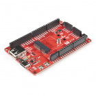
The SparkFun Thing Plus Matter - MGM240P is the first easily accessible board of its kind that combines Matter® and SparkFun's Qwiic ecosystem for agile development and prototyping of Matter-based IoT devices. The board features the MGM240P wireless module from Silicon Labs®. The MGM240P provides secure connectivity for both 802.15.4 (Matter, Zigbee®, and OpenThread®) and Bluetooth Low Energy 5.3 protocols and is built to integrate seamlessly into the Matter IoT protocol using the Simplicity Studio IDE from Silicon Labs.

SparkFun Thing Plus Matter - MGM240P

SparkFun Thing Plus Matter - MGM240P

DEV-20270
$24.95

You may be curious as to what exactly Matter is. In a nutshell, Matter allows for consistent operation between smart home devices and IoT platforms without an Internet connection, even from different providers. This allows communication between major IoT ecosystems to create a single wireless protocol that is easy, reliable and secure to use.

This guide covers the hardware present on this Thing Plus development board, basic assembly, and a quick intro to using the Thing Plus Matter in Silicon Labs' Simplicity Studio development environment.

Required Materials

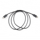
All you need to follow along with this tutorial is the SparkFun Thing Plus MGM240P as well as a USB-C cable to connect it to your computer for programming. You may also want a single-cell LiPo battery to power the board in your application.

USB 3.1 Cable A to C - 3 Foot

USB 3.1 Cable A to C - 3 Foot

CAB-14743
$5.50
4
Reversible USB A to C Cable - 2m

Reversible USB A to C Cable - 2m

CAB-15424
$8.95
1
Reversible USB A to C Cable - 0.3m

Reversible USB A to C Cable - 0.3m

CAB-15426
$4.50
1

Optional Accessories

Depending on your application's needs, you may want some additional accessories along with the Thing Plus Matter - MGM240P and USB-C cable.
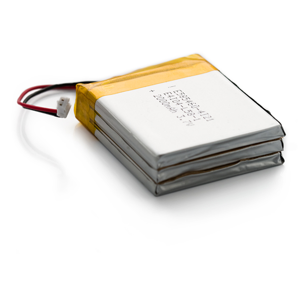
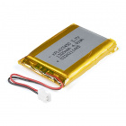
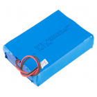
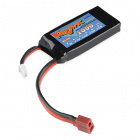
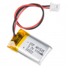
LiPo Battery

The Thing Plus Matter includes a 2-pin JST connector to connect a single-cell lithium-ion battery for power in mobile applications. Below are a few options we recommend:
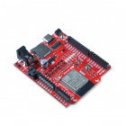
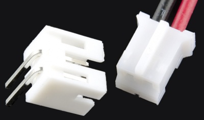
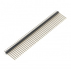
Lithium Ion Battery - 400mAh

Lithium Ion Battery - 400mAh

PRT-13851
$5.50
10
Lithium Ion Battery - 2Ah

Lithium Ion Battery - 2Ah

PRT-13855
$13.95
9
Lithium Ion Battery - 1Ah

Lithium Ion Battery - 1Ah

PRT-13813
$10.95
8
Lithium Ion Battery - 110mAh

Lithium Ion Battery - 110mAh

PRT-13853
$5.50
3

Headers

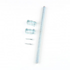
Headers allow you connect external parts to your board with just a set of jumper wires for prototyping circuits with a breadboard. The list below outlines a few options we recommend. If you don't find what you need, check out our Headers Category. If you need soldering tools, head over to our Soldering Category:

Break Away Headers - Straight

Break Away Headers - Straight

PRT-00116
$1.75
20
SparkFun Beginner Tool Kit

SparkFun Beginner Tool Kit

TOL-14681
$62.50
Break Away Headers - Long

Break Away Headers - Long

PRT-10158
$3.25
3
Feather Stackable Header Kit

Feather Stackable Header Kit

PRT-15187
$1.75

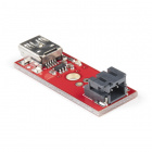
Solder Jumper Modification

The Thing Plus Matter - MGM240P has several solder jumpers users can modify to change behavior on the board. Modifying the jumpers requires a knife and soldering equipment. The list below covers some recommended options but in case you do not find what you need there, head over to our Soldering Category:

Solder Lead Free - 100-gram Spool

Solder Lead Free - 100-gram Spool

TOL-09325
$9.95
8
Weller WLC100 Soldering Station

Weller WLC100 Soldering Station

TOL-14228
2
Chip Quik No-Clean Flux Pen  - 10mL

Chip Quik No-Clean Flux Pen - 10mL

TOL-14579
$8.95
4
Hobby Knife

Hobby Knife

TOL-09200
$3.50
2

Suggested Reading

Before getting started with this Hookup Guide, you may want to read through the tutorials below if you are not familiar with the concepts covered in them or want a refresher:

How to Solder: Through-Hole Soldering

This tutorial covers everything you need to know about through-hole soldering.

Serial Communication

Asynchronous serial communication concepts: packets, signal levels, baud rates, UARTs and more!

Serial Peripheral Interface (SPI)

SPI is commonly used to connect microcontrollers to peripherals such as sensors, shift registers, and SD cards.

Logic Levels

Learn the difference between 3.3V and 5V devices and logic levels.

I2C

An introduction to I2C, one of the main embedded communications protocols in use today.

Analog vs. Digital

This tutorial covers the concept of analog and digital signals, as they relate to electronics.

Bluetooth Basics

An overview of the Bluetooth wireless technology.

How to Work with Jumper Pads and PCB Traces

Handling PCB jumper pads and traces is an essential skill. Learn how to cut a PCB trace, add a solder jumper between pads to reroute connections, and repair a trace with the green wire method if a trace is damaged.

Hardware Overview

In this section we'll take a closer look at the MGM240P as well as other hardware present on the Thing Plus Matter - MGM240P.
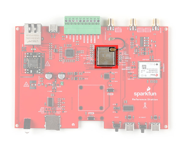
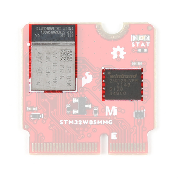
MGM240P

The MGM240P wireless module provides a secure solution for both 802.15.4 (Matter, Zigbee, and OpenThread) and Bluetooth Low Energy 5.3 protocols, and is designed to integrate seamlessly into the Matter IoT convention. Matter aims to simplify and consolidate major Smart Home IoT ecosystems into a single, secure, and easy to use protocol.

Photo highlighting the MGM240P and J-Link debugger IC.

The MGM240P is built around Silicon Labs' EFR32MG24 wireless system-on-chip (SoC) that includes a 32-bit ARM Cortex M33 core processor and integrated 2.4 GHz radio, 1536 kB Flash memory, and 256 kB of RAM. The Thing Plus runs the MGM240P at 3.3V by default when powered by USB or a battery. The module has a dedicated processor core for security to allow for use with Silicon Labs' Secure Vault IoT security feature suite along with a host of software-configurable options using the Simplicity Studio IDE. This Thing Plus specifically uses the MGM240PB32VNA variant of the module which uses a built in antenna with a max transmit power of +20 dBm. For a complete overview of the MGM240P refer to the datasheet.

J-Link Debugger

The board uses the EFM32GG12B410F1024GL120-A microcontroller as a J-Link programmer and debugging IC. The Mini Simplicity Connector on the board allows users to connect an external debugger if they wish. The board pulls the debugger WAKE pin to V_USB through the LP jumper by default to have it operate in standard mode. Users can open this jumper to force the debugger into Low Power mode.

The debugger allows some seriously low-level debugging tools when used with Simplicity Studio's debugging tool. You can perform all sorts of standard debugging actions such as debugger output, placing code breaks, and can even get as granular as looking at the assembly code.
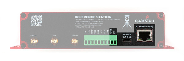
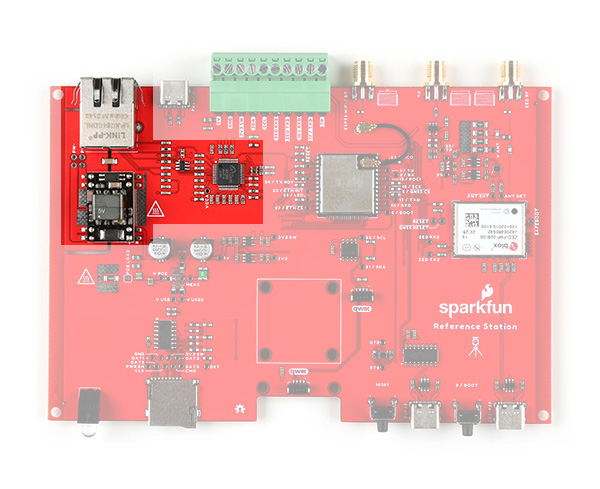
Power

The Thing Plus Matter - MGM240P offers several ways to power the board. The primary power options are the USB-C connector (also used for programming/serial communication) and 2-pin JST connector for a single-sell LiPo battery. The board includes the necessary components to charge and monitor the charge level of a connected battery.

Photo highlighting power components.

The board also has PTH pins connected to the 3.3V, V_USB, and V_BATT nets.

USB-C

The USB-C connector on the board provides power, battery charging voltage, and a serial connection for programming and interfacing. The board also includes a USB shield jumper that controls whether or not the USB shield pin on an attached cable connects to the board's ground plane.

The 5V from V_USB connects to the 3.3V regulator as well as the VIN on the LiPo battery charger so the MCP73831 is powered with voltage present from USB so long as the CHG solder jumper is set to either current setting. Opening the jumper disables the MCP73831.

LiPo Connector and Charge Circuit

The board includes a 2-pin JST connector to plug a single-cell LiPo battery in for battery powered applications. The input voltage is regulated by a 3.3V voltage regulator. The board also features a MCP73831 Single-Cell LiPo Charge IC to recharge a connected battery when plugged in over USB-C as well as a MAX17048 Single-Cell fuel gauge to monitor battery charge level.

By default the charge current is set to 500mA. A three-way jumper labeled CHG allows users to switch between 500mA charge current to 100mA as well as disabling the charge IC when not needed. More on this and all other solder jumpers in the Solder Jumpers section below.
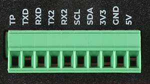
Pinout

The MGM240P has 26 General Purpose Input/Output (GPIO) pins that are all individually configurable through software to act as I/O pins, peripherals (SPI, I2C, etc.) or other advanced configurations such as open-drain. This allows remapping of any GPIO to any supported functionality.

Photo highlighting PTH pinout.

The Thing Plus Matter - MGM240P breaks out 23 of these pins to PTHs on either side of the board. The board settings configures them to deliver the following functionality:

  • Serial - TX/RX
  • I2C - SDA/SCL
  • SPI - POCI/PICO/SCK
  • Analog - A0-A5*
  • GPIO - 0-6*
  • Freebie - Feather-compatible Freebie pin tied to PC07
  • Reset
  • Enable
Note: Despite their labels, all GPIO pins (A0-A5 and GPIO0-GPIO6) function as either GPIO or analog.

Peripheral Accessories

The Thing Plus MGM240P includes several peripheral accessories that allow users quick access to several features. Let's take a brief look at them.

Highlighting Qwiic connector and Mini Simplicity connector.Highlighting the micro SD slot.

Mini Simplicity Connector

The Mini Simplicity Connector allows users a quick and direct option to connect an external debugger to the board.
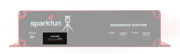
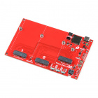
Note: An external Mini Simplicity debugger plugged into the board connects to the serial (TX/RX) pins of the on-board debugger IC meaning only one debugger is available at a time (either external or on-board).

µSD Slot

The µSD card slot provides an option to connect a µSD card for extra memory space to the Thing Plus.
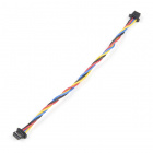
Qwiic Connector

The Qwiic connector provides a fast connection to the I2C bus to use with SparkFun's ever-growing Qwiic ecosystem.
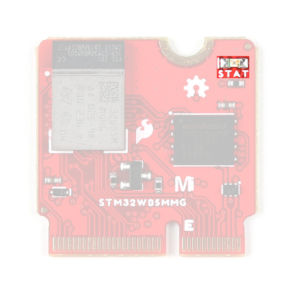
LEDs

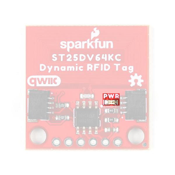
This board has four LEDs labeled PWR, STAT, CHG, and DBG.

Highlighting the four LEDs.
  • Power (PWR) LED - Indicates power supplied to the board.
  • Status (STAT) LED - Tied to A8 for use as a general status indicator.
  • Charge (CHG) LED - Indicates whether or not the charge circuit is actively charging an attached LiPo battery.
  • Debugger (DBG) LED - Connects to the debugger IC's status output and can provide visual indication for debug behavior.
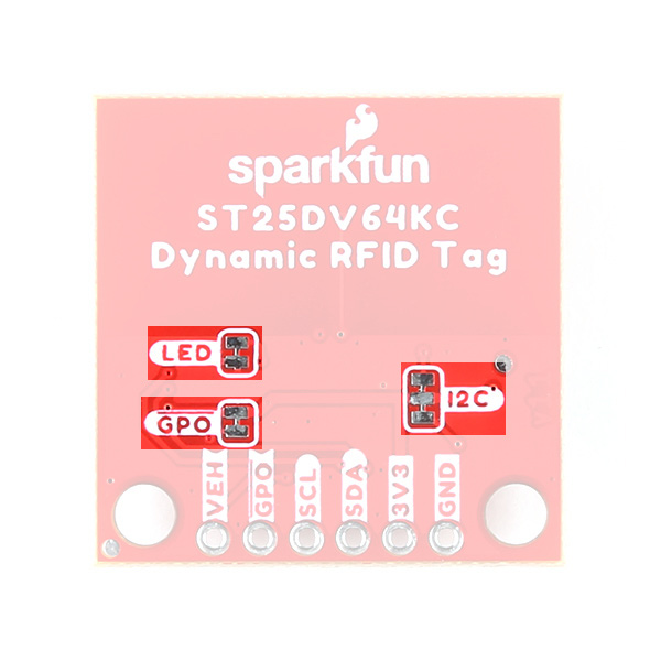
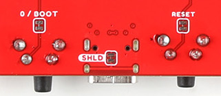
Solder Jumpers

If you have never worked with solder jumpers and PCB traces before or would like a quick refresher, check out our How to Work With Solder Jumpers and PCB Traces tutorial for detailed instructions and tips.

The board has nine solder jumpers for user customization. The table below outlines the jumper's label, default state, function, and any notes regarding how to use them.

Highlighting the nine solder jumpers.
Jumper LabelDefault StateFunctionNotes
PWRCLOSEDCompletes the Power LED circuitOpen to disable the Power LED.
CHGCLOSEDCompletes the Charge LED circuit.Open to disable the Charge LED.
I2CCLOSEDTies SDA/SCL (PB04/PB03 respectively) to 3.3V through a pair of 2.2kΩ resistorsOpen to disable pullup resistors on these pins.
CHG_ISEE NOTEThree-way jumper sets the charge current for the LiPo charge circuit.Default setting is 500mA (0.5A label). Alternate is 100mA (0.1A label). Open completely to disable LiPo charger.
JP1SEE NOTEThree-way jumper that routes the MGM240P's RESET pin either to the Reset Button (Default) or the A0 PTH.Connect the JP1 jumper to the A0 side to reroute the RESET pin to allow toggling of A0 by an external connection to reset the MGM240P.
D3CLOSEDTies A0 PTH to PD03.Open to isolate PD03 if JP1 is set to the A0 side.
SHLDCLOSEDConnects the USB-C shield pin to the PCB's ground plane.Open to isolate the USB-C shield pin from the ground.
MEASCLOSEDCompletes the power input circuit.Open and use a digital multimeter to complete the circuit and measure current drawn by the board.
LPCLOSEDTies the J-Link debugger IC Wake pin to V_USB.Open to force the debugger into Low Power mode. Open for battery powered applications where V_USB is present through a charging bank on USB-C connector.

Board Dimensions

The Thing Plus - MGM240P matches the Thing Plus footprint to work with all Thing Plus-compatible accessories and shields and measures 2.30" x 0.90" (58.42mm x 22.86mm). The two mounting holes on this Thing Plus fit a 4-40 screw

Board dimensions.

Hardware Assembly

Now that we're familiar with the hardware on this Thing Plus it's time to assemble the board into a prototyping circuit or simply plug it into our computer with a USB-C cable and get right to programming.

Basic Assembly

For those who want to jump right in to using the Thing Plus Matter - MGM240P on its own or just with the wireless capabilities, all you need to do is plug the board into your computer using a USB-C cable.

Thing Plus Matter connected over USB.

Soldering Headers

Users who want to assemble a prototyping circuit with the Thing Plus should solder headers of their choice to the board to plug it into a breadboard. We recommend something like this Feather Stackable Header Kit.

Software Setup

The MGM240P uses Silicon Labs' Simplicity Studio IDE as a development tool for programming, debugging, customizing, etc. In this section we'll cover the basics of installing the IDE and adding the Thing Plus Matter.

Install and Open Simplicity Studio

Simplicity Studio is available for Windows, Mac OSX and Ubuntu operating systems. You can find the installer download for your operating system by clicking the button below:

Silicon Labs requires you to create a (free) account to download Simplicity Studio so make one if you do not have one already. Once the installer finishes downloading, open it and follow the installation instructions.

Simplicity Studio Launcher

When you first open Simplicity Studio you'll be greeted by the Launcher window. The default Launcher window lets users install board files for both connected devices and by searching for a supported product. It also lists any recent projects you've worked on as well as links to user guides and support documentation.

Screenshot of welcome page for Simplicity Studio.
Having trouble seeing the detail in this image? Click on it for a larger view.

On the left side there are two windows for any debug adapters (top) and all installed products (bottom). In the very top right of the screen you'll see the tabs to switch between the launcher, the Simplicity IDE and the Debug window. We'll be using the IDE tab in the next section once we finish installing the Thing Plus Matter into Simplicity Studio.

Adding the Thing Plus Matter - MGM240P

Simplicity Studio makes adding devices extremely easy by just connecting the device to your computer over USB and then selecting "Connected Devices". It automatically checks the device ID to matching supported products and should display either as a J-Link Silicon Labs debugger (prior to install) or "SparkFun Thing Plus MGM240P" as the connected device.

Silicon Labs screenshot with Thing Plus connected but not installed.
Having trouble seeing the detail in this image? Click on it for a larger view.

With the connected Thing Plus selected, click "Start". This opens the Installation Manager window where you can select either "Auto" or "Advanced" installation. Most users should select "Auto" and then click "Next". You'll be prompted to agree to licensing agreements. Once you have agreed, click "Finish" and it will install all necessary software, drivers and other packages to use the Thing Plus Matter in Simplicity Studio.

Screenshot of the installation manager.

The install process can take a few minutes and once it completes you'll need to restart the program. After restarting, your Launcher window should update and look similar to the screenshot below:

Silicon Labs launcher screenshot after installation.
Having trouble seeing the detail in this image? Click on it for a larger view.

This window contains several tabs that cover the general overview of the board, examples, documentation and compatible tools. Feel free to explore as much as you'd like but for now we'll move on to a basic "Blink" example to make sure everything was set up correctly and the Thing Plus Matter is working.

Silicon Labs Documentation

For comprehensive information on using Simplicity Studio, Silicon Labs has an in-depth user guide for the IDE available here:

If you're itching to integrate your Thing Plus with a Matter-compatible device, Silicon Labs has documentation for Matter development here:

They also have much more documentation covering other applications including Thread, other wireless protocols, and the Gecko SDK used in Simplicity Studio available on their main documentation page here:

Now that the Thing Plus Matter - MGM240P is installed in Simplicity Studio we can move on to a basic test to make sure everything is working as intended. For this example we'll be setting up and uploading a Blink test to turn the Status LED on and off.

Blink Example

In the Launcher with the SparkFun Thing Plus MGM240P selected for your product, navigate to the "Example Projects & Demos" tab. Now type "Blink" into the "Filter on keywords" search bar and select "Platform - Blink Bare-metal" and click "Create".

Screenshot of "blink" search in Example Projects and Demos.
Having trouble seeing the detail in this image? Click on it for a larger view.

This opens the New Project Wizard window where you can change the project name, filepath, and project file options. For now, leave all of that with the default settings and click "Finish".

Screenshot of Project Wizard window.

Once you've created the new project you can double-click on the containing folder in the "Project Explorer" window to open all the files included with the Blink project which includes any binaries, configs, header and C files if you prefer. For now, we're just going to build and flash the project to get the Status LED blinking. To do that, right click on the "blink_baremetal" folder and scroll down to "Run As" and select "1 Silicon Labs ARM Program". This builds and flashes the project to your board and once it completes the Blue STAT LED should be blinking on and off every second.

Screenshot of selecting "Run As" option.
Having trouble seeing the detail in this image? Click on it for a larger view.

This is obviously one of the most basic projects for the Thing Plus Matter so from here you can explore other example projects and demos for the Thing Plus or start building your own.

Troubleshooting

Power Consumption Tips

Power consumption by this board varies depending on how it is configured and powered. Below are our current consumption test results for various power options with the MGM240P operating in Low Power mode:

  • Regulated 3.3V input on 3V3 pin - 15µA
  • LiPo JST Connector/VBAT pin - 120µA
  • USB-C/VUSB pin (LP and CHG jumpers cut) - 250µA
  • USB-C/VUSB pin (only LP jumper cut) - 300µA
  • USB-C/VUSB pin (neither jumper cut) - 21mA

As you can see, for lowest current consumption, powering the board with a regulated 3.3V input directly to the 3.3V pin draws significantly less current as it bypasses the voltage regulator and battery charge/monitoring components. All of these tests were performed with the PWR jumper OPEN to disable the Power LED.

Driver Installation

Most operating systems will not recognize the Thing Plus Matter as a USB device by default. To install drivers, download and install the Simplicity Studio IDE and then install the Thing Plus Matter package to the IDE. This process will install all necessary board packages for the Thing Plus including USB drivers. Refer to our Getting Started with Simplicity Studio guide or Silicon Labs' Simplicity Studio documentation for detailed instructions.

General Troubleshooting

Resources and Going Further

That's all for this guide. For more information about the SparkFun Thing Plus Matter - MGM240P, check out the following resources:

SparkFun Thing Plus Matter - MGM240P Resources

Silicon Labs Resources


learn.sparkfun.com | CC BY-SA 3.0 | SparkFun Electronics | Niwot, Colorado


Qwiic Dynamic NFC/RFID Tag Hookup Guide

$
0
0

Qwiic Dynamic NFC/RFID Tag Hookup Guide a learn.sparkfun.com tutorial

Available online at: http://sfe.io/t3012

Introduction

The SparkFun Qwiic Dynamic NFC/RFID Tag features the ST25DV64KC dynamic Near Frequency Communication (NFC) / Radio Frequency Identification (RFID) tag IC from STMicroelectronics©. The ST25DV64KC offers 64-kBit (8-kBytes) of EEPROM memory which can be accessed over both I2C and RF (NFC)! It's a state-of-the-art tag which conforms to ISO/IEC 15693 or NFC Forum Type 5 recommendations. You can read and write the tag's memory using NFC even while the tag is powered down or disconnected!

SparkFun Qwiic Dynamic NFC/RFID Tag

SparkFun Qwiic Dynamic NFC/RFID Tag

SEN-21274
$9.95

In this guide we'll go into some detail on the ST25DV64KC IC and other hardware on this Qwiic breakout, how to assemble it into a Qwiic circuit and then install the SparkFun ST25DV64KC Arduino Library.

Required Materials

To follow along with this guide you will need a microcontroller to communicate with the Qwiic Dynamic NFC/RFID Tag. Below are a few options that come Qwiic-enabled out of the box:

SparkFun Thing Plus - ESP32 WROOM (Micro-B)

SparkFun Thing Plus - ESP32 WROOM (Micro-B)

WRL-15663
$22.50
10
SparkFun RedBoard Plus

SparkFun RedBoard Plus

DEV-18158
$21.50
4
SparkFun RedBoard Artemis

SparkFun RedBoard Artemis

DEV-15444
$21.50
10
SparkFun Thing Plus - Artemis

SparkFun Thing Plus - Artemis

WRL-15574
$22.50

If your chosen microcontroller is not already Qwiic-enabled, you can add that functionality with one or more of the following items:

SparkFun Qwiic Cable Kit

SparkFun Qwiic Cable Kit

KIT-15081
$8.95
18
SparkFun Qwiic Adapter

SparkFun Qwiic Adapter

DEV-14495
$1.60
1
SparkFun Qwiic Shield for Arduino

SparkFun Qwiic Shield for Arduino

DEV-14352
$7.50
8
SparkFun Qwiic Shield for Thing Plus

SparkFun Qwiic Shield for Thing Plus

DEV-16790
$4.95

You will also need at least one Qwiic cable to connect your sensor to your microcontroller.

Qwiic Cable - 100mm

Qwiic Cable - 100mm

PRT-14427
$1.50
Qwiic Cable - 50mm

Qwiic Cable - 50mm

PRT-14426
$0.95
Qwiic Cable - 500mm

Qwiic Cable - 500mm

PRT-14429
$1.95
1
Qwiic Cable - 200mm

Qwiic Cable - 200mm

PRT-14428
Retired

Optional Materials

Suggested Reading

If you aren't familiar with the Qwiic system, we recommend reading here for an overview.

Qwiic Connect System

We also recommend taking a look at the following tutorials if you aren't familiar with the concepts covered in them. If you are using one of the Qwiic Shields listed above, you may want to read through their respective Hookup Guides as well before you get started with the Qwiic Dynamic NFC/RFID Tag.

I2C

An introduction to I2C, one of the main embedded communications protocols in use today.

RFID Basics

Dive into the basics of Radio Frequency Identification (RFID) technology.

Qwiic Shield for Arduino & Photon Hookup Guide

Get started with our Qwiic ecosystem with the Qwiic shield for Arduino or Photon.

SparkFun Qwiic Shield for Arduino Nano Hookup Guide

Hookup Guide for the SparkFun Qwiic Shield for Arduino Nano.

Hardware Overview

Let's take a closer look at the ST25DV64KC and other hardware present on the Qwiic Dynamic NFC/RFID Tag.

ST25DV64KC Dynamic NFC/RFID Tag

The ST25DV64KC from STMicroelectronics is a unique tag IC that communicates over both I2C and RF (NFC). It conforms to ISO/IEC 15693 (13.56 MHz frequency) and NFC Forum Type 5 recommendations.

Highlighting the ST25DV64KC IC.

The ST25DV64KC includes 64 Kbit EEPROM for users to write and read data from, a general purpose output to act as an external interrupt reporting events such as RF field changes, RF activity, I2C writes and RF switch toggling over I2C. The IC has a supply voltage range of 1.8V to 5.5V though when in a Qwiic circuit it runs at 3.3V. It also includes an energy harvesting pin capable of outputing µW of power with an RF field of sufficient strength. For a complete overview of the ST25DV64KC, refer to the datasheet.

The ST25DV64KC supports a fast transfer mode to send the contents of a 256 byte buffer between a device connected to the tag over I2C (refered to as the tag's Mailbox) and an RF device such as a reader or smartphone. This makes it so you can store data on the tag and have it available for reading by an RF device by simply bringing it into the RF read range, even if the tag is powered off. This data can also be password protected with a 64-bit value.

Power and Communication Interfaces

The Qwiic Dynamic NFC/RFID Tag has two interfaces for powering and communicating with the ST25DV64KC: a pair of Qwiic connectors and a plated through hole (PTH) header.

Qwiic Connector

The board has a pair of Qwiic connectors to integrate it into a Qwiic ecosystem.

Highlighting the Qwiic connectors.

The Qwiic connectors route the SDA/SCL connections as well as 3.3V and Ground to power the board and communicate with the ST25DV64KC over I2C.

Plated Through Hole Header

The board has a 0.1"-spaced PTH header that breaks out the power pins (3.3V and Ground), I2C interface (SDA/SCL), energy harvesting pin (VEH), and general purpose output pin (GPO).

Highlighting the PTH header.

The Energy Harvesting Pin outputs an analog voltage when energy harvesting mode is enabled and in the presence of a strong enough RF field. Refer to section 5.5 of the datasheet for specifics on using this pin. The General Purpose Output is an open-drain configurable pin used for interrupt events.

Antenna

The board includes a PCB antenna for the ST25DV64KC to help boost the read range a bit. In our testing with a smart phone running an NFC reader app we found it had a range of a few centimeters.

Highlighting the PCB antenna.

LED

The sole LED on this board is a power status LED.

Highlighting the Power LED.

Solder Jumpers

The board has three solder jumpers labeled LED, GPO and I2C. The table below outlines their labels, default state, functionality, and any notes regarding their use.

Highlighting the solder jumpers.
LabelDefault StateFunctionNotes
LEDCLOSEDCompletes the Power LED circuit.Open to disable the Power LED.
GPOCLOSEDPulls the interrupt (GPO) pin HIGH through a 10kΩ resistor.Open to disable the pullup resistor.
I2CCLOSEDPulls the SDA/SCL lines to VCC (3.3V) through a pair of 2.2kΩ resistors.Open to disable the pullup resistors.

Board Dimensions

The Qwiic Dynamic NFC/RFID Tag matches the standard Qwiic breakout size of 1" x 1" (25.4mm x 25.4mm) and has two mounting holes that fit a 4-40 screw.

Board dimensions

Hardware Assembly

Now that we're familiar with the hardware on the Qwiic Dynamic NFC/RFID Tag, it's time to assemble it into a Qwiic circuit.

Basic Assembly

The Qwiic ecosystem makes building a circuit with the Qwiic Dynamic NFC/RFID Tag simple. Just use a Qwiic cable to connect the breakout to your development board like the image shown below:

Qwiic circuit assembled.

As a reminder, the Qwiic connectors only include the power pins and I2C lines so if you wish to use the Energy Harvesting pin or the General Purpose pin you'll need to solder to them or use something like these IC Hooks for a temporary prototyping connection.

Soldered Assembly

Users who prefer a traditional soldered connection should solder headers or wires to the Qwiic Dynamic NFC/RFID Tag and then make the appropriate connections to your development board. If you've never soldered before or would like some tips, check out our How to Solder Tutorial.

SparkFun ST25DV64KC Arduino Library

Note: This library assumes you are using the latest version of the Arduino IDE on your desktop. If this is your first time using Arduino, please review our tutorial on installing the Arduino IDE. If you have not previously installed an Arduino library, please check out our installation guide.

The SparkFun ST25DV64KC Arduino Library provides an exhaustive collection of examples to take full advantage of the Qwiic Dynamic NFC/RFID Tag including reading and writing the user memory, controlling the read/write permissions, altering the read area sizes, and applying password control. On top of this the library includes examples showing how to use NDEF (NFC Forum Data Exchange Format) URI, WiFi, and Text records you can read with a smart phone. You'll need a compatible app on your phone like ST's "NFC Tap" App available on the Apple© App store or Google© Play.

Install the library into Arduino by searching for "SparkFun ST25DV64KX Arduino Library" in the Arduino Library Manager. Users who prefer to install the library manually can download it by clicking the button below:

Arduino Library Documentation

We have an in-depth guide for the library covering all examples as well as the complete API reference you can read through here:

Troubleshooting

General Troubleshooting

Resources and Going Further

That's all for this guide. For more information about the Qwiic Dynamic NFC/RFID Tag, check out the resources below:

Looking for inspiration on projects to use the Qwiic Dynamic NFC/RFID Tag in? These tutorials may get you pointed in the right direction:

RFID Basics

Dive into the basics of Radio Frequency Identification (RFID) technology.

Build a Qwiic Jukebox that is Toddler Approved!

Follow this tutorial to build your own custom jukebox. Note, this is designed simple and tough for use primarily with toddlers. It's also a great introduction to SparkFun's Qwiic products!

RFID Beginners Tutorial

In this tutorial we'll revisit some RFID basics and practice by making a remote work logger using an RFID reader and a GPS module. You'll scan a card and get ID, location, and time. All the perfect data to punch in and punch out from the middle of Nowhere!

learn.sparkfun.com | CC BY-SA 3.0 | SparkFun Electronics | Niwot, Colorado

Single Cell LiPo Battery Care

$
0
0

Single Cell LiPo Battery Care a learn.sparkfun.com tutorial

Available online at: http://sfe.io/t3045

Introduction

Note: This tutorial was ported over from the older LiPo Battery Care tutorial. Tips from the LilyPad Basics: Powering Your Project (Power Options: Rechargeable Lithium Polymer Batteries) were also added to this tutorial.

Lithium-Ion Polymer (LiPo) batteries are a favorite of ours. Very light weight and some of the highest energy densities available. We affectionately call this battery the 'car battery' because it's huge. Not physically (it's 110 grams!) but because this 6Ah LiPo in capable of outputting 6 Amps over the period of one hour! This is a very large amount of power in our low-power embedded world. Please don't confuse this with a real car battery!

alt text

A battery capable of producing 6 Amps for one hour!

Required Materials

To follow along with this tutorial, you will need the following materials at a minimum. You may not need everything though depending on what you have. Add it to your cart, read through the guide, and adjust the cart as necessary. Below is a wishlist of the parts that you need to get started if you were to charge a LiPo battery and then remove the connector.

Single Cell LiPo Chargers

There are a variety of development boards and breakout boards with a dedicated single cell LiPo battery charge circuit. Below are a few examples from the SparkFun catalog that have the MCP73831. The charge IC used and charge rate will depend on the design.

SparkFun IoT RedBoard - ESP32 Development Board

SparkFun IoT RedBoard - ESP32 Development Board

WRL-19177
$29.95
3
SparkFun Adjustable LiPo Charger

SparkFun Adjustable LiPo Charger

PRT-14380
$13.50
4
SparkFun MicroMod Main Board - Single

SparkFun MicroMod Main Board - Single

DEV-20748
$15.95
SparkFun LiPo Charger Basic - Mini-USB

SparkFun LiPo Charger Basic - Mini-USB

PRT-10401
$10.50
3

Single Cell LiPo Battery

Of course, you will also need a single cell LiPo battery. Below are a few LiPo batteries to choose from in the SparkFun catalog.

Lithium Ion Battery - 1250mAh (IEC62133 Certified)

Lithium Ion Battery - 1250mAh (IEC62133 Certified)

PRT-18286
$10.95
1
Lithium Ion Battery - 400mAh

Lithium Ion Battery - 400mAh

PRT-13851
$5.50
10
Lithium Ion Battery - 850mAh

Lithium Ion Battery - 850mAh

PRT-13854
$10.95
2
Lithium Ion Battery - 6Ah

Lithium Ion Battery - 6Ah

PRT-13856
$32.50
7

Tools

Need some help removing the single cell LiPo battery from the JST connector? Try grabbing a needle nose plier or diagonal cutters. Or you can use a hobby knife to whittle down the JST-PH's locking tabs.

Needle Nose Pliers

Needle Nose Pliers

TOL-08793
$3.50
1
Diagonal Cutters

Diagonal Cutters

TOL-08794
$2.75
3
Hobby Knife

Hobby Knife

TOL-09200
$3.50
2

You May Also Need

For strain relief, you can use some electrical tape and scissors to secure the wires on the single cell LiPo battery. You may want a marker to label the battery.

  • Electrical Tape
  • Scissors
  • Marker

Suggested Reading

If you aren’t familiar with the following concepts, we also recommend checking out a few of these tutorials before continuing

Connector Basics

Connectors are a major source of confusion for people just beginning electronics. The number of different options, terms, and names of connectors can make selecting one, or finding the one you need, daunting. This article will help you get a jump on the world of connectors.

Battery Technologies

The basics behind the batteries used in portable electronic devices: LiPo, NiMH, coin cells, and alkaline.

How Lithium Polymer Batteries are Made

We got the opportunity to tour the Great Power Battery factory. Checkout how LiPos are made!

How to Use a Multimeter

Learn the basics of using a multimeter to measure continuity, voltage, resistance and current.

What is a Battery?

An overview of the inner workings of a battery and how it was invented.

Charging LiPo Batteries, Safely

Back in the old days, there were only two chargers available in SparkFun's catalog. The standard charger based on the old MAX1555 IC and our faster charger based on the newer MCP73831 IC. You will notice the MAX1555 and MCP73831 populated as a 5-pin IC as shown in the images below. The MAX1555 was great but its limited charging current (300mA) and diminishing market availability way back when pushed us towards creating chargers based on the MCP73831 (500mA per hour charging rate).

Retired USB Single Cell LiPo Charger with MAX1555USB Single Cell LiPo Charger with MCP73831

You will notice the MCP73831 populated on select development boards and a variety of breakout boards with different USB connectors. Below are a few examples with the MCP73831 populated on different boards found in the SparkFun catalog.

SparkFun IoT RedBoard - ESP32 Development Board

SparkFun IoT RedBoard - ESP32 Development Board

WRL-19177
$29.95
3
SparkFun Adjustable LiPo Charger

SparkFun Adjustable LiPo Charger

PRT-14380
$13.50
4
SparkFun MicroMod Main Board - Single

SparkFun MicroMod Main Board - Single

DEV-20748
$15.95
SparkFun LiPo Charger Basic - Mini-USB

SparkFun LiPo Charger Basic - Mini-USB

PRT-10401
$10.50
3

Other notable LiPo chargers in the SparkFun catalog is the BQ24075 populated on the Battery Babysitter - LiPo Battery Manager, and LT3652 populated on the Sunny Buddy - MPPT Solar Charger. Both can be used to charge a single cell LiPo battery through USB or a solar panel, respectively.

SparkFun Sunny Buddy - MPPT Solar Charger

SparkFun Sunny Buddy - MPPT Solar Charger

PRT-12885
$28.95
10
SparkFun Battery Babysitter - LiPo Battery Manager

SparkFun Battery Babysitter - LiPo Battery Manager

PRT-13777
$21.50
10

Recommended Charge Rate for Single Cell LiPo Batteries

To avoid explosions (which are only very briefly fun), you should not charge these LiPos at a current over the battery's capacity, typically 1C for fast charging. To be safe [1], you should keep the charge current at or below 1C of your battery as indicated in the datasheets.

What does this mean? Well, lets take a look at the datasheet for the 850mAh LiPo battery. The image shown below highlights the recommended standard charge rate and maximum continuous charge current, where C is the capacity of the LiPo battery. For a standard charge rate of 0.2C, an 850mAh LiPo battery can be charged at a rate of 170mA. When charging at the maximum charge rate of 1C, an 850mAh LiPo battery can be charged at a rate of 850mA.

alt text

Datasheet highlighted for the 850mAh LiPo Battery's Charge Rates

What does this mean with the LiPo chargers available? Well, if you have an 500mAh single cell LiPo battery, it should not be given a charge current over 500mA. You should use a charger that is able to charge the LiPo battery with a dedicated single cell LiPo charger set at or below 500mA. The minimum LiPo battery that SparkFun has available currently that is compatible at this rate that you can safely charge is 850mAh. Other larger single cell LiPo batteries can also be charged at this rate.

Lithium Ion Battery - 1250mAh (IEC62133 Certified)

Lithium Ion Battery - 1250mAh (IEC62133 Certified)

PRT-18286
$10.95
1
Lithium Ion Battery - 850mAh

Lithium Ion Battery - 850mAh

PRT-13854
$10.95
2
Lithium Ion Battery - 2Ah

Lithium Ion Battery - 2Ah

PRT-13855
$13.95
9
Lithium Ion Battery - 1Ah

Lithium Ion Battery - 1Ah

PRT-13813
$10.95
8
Lithium Ion Battery - 6Ah

Lithium Ion Battery - 6Ah

PRT-13856
$32.50
7

What about a 100mAh LiPo battery? Yeah, those should not be charged higher than 100mA. Make sure to find a single cell LiPo charger that is set at or below 100mA. The minimum LiPo battery that SparkFun has available currently that is compatible at this rate that you can safely charge is 110mAh. Other larger single cell LiPo batteries (like the 400mAh shown below or any of the ones shown earlier) can also be charged at this rate.

Lithium Ion Battery - 400mAh

Lithium Ion Battery - 400mAh

PRT-13851
$5.50
10
Lithium Ion Battery - 110mAh

Lithium Ion Battery - 110mAh

PRT-13853
$5.50
3

Depending on the designer, the charge rate can be set to a default rate of either 500mA or 100mA. Certain boards can have a 3-way jumper, switches, and/or PTH footprint to solder a resistor to adjust the charge rate. Below is a schematic of the USB LiPoly Charger. As you can see, this particular board is set at a default rate of 500mA with a 3-way jumper. Cutting the jumper and adding a solder blob between the center pad and the other jumper pad will set the charge rate to 100mA.

alt text

But what about that lone 40mAh LiPo Battery in SparkFun's catalog?! If you look closely at the schematic shown earlier, there is also a footprint (not currently highlighted but it is connected to the same net) that allows users to solder a PTH resistor. This allows a user to set the charge rate to a value other than 500mA or 100mA. There's not that a lot of development boards and breakout boards that have the footprint available. Make sure to be careful when connecting a USB cable to those boards when a 40mAh battery is attached. You will want to remove the battery and connect the LiPo battery to a separate LiPo Charger that is set at or below 40mA.

Polymer Lithium Ion Battery - 40mAh

Polymer Lithium Ion Battery - 40mAh

PRT-13852
$4.95

To calculate the resistor needed on a board with the MCP73831, you can use the following formula from its datasheet. Note that this equation is specific for the MCP73831 charge IC.

\I_{charge} = \frac{1000V}{R_{prog}}\;\; \mathrm{(or)}\;\; R_{prog} = \frac{1000V}{I_{charge}}

We'll just skip ahead of the calculations and tell you that the value to charge at a rate of 40mA is... 25kΩ! This is quite an odd number for a resistor value in SparkFun's catalog. You'll need to wire a few resistors wired in series and parallel to connect to the two PTHs (i.e. 10kΩ + 10kΩ + (10kΩ || 10kΩ) ). Or you could use resistor with a larger value like 47kΩ that is included in the resistor kit. However, the charge rate will be less: 21.28mA.

Connecting and Disconnecting a LiPo Battery's JST Connector

Depending on the manufacturer, there are different packages and connections for Lithium batteries. We will be going over how to connect and disconnect batteries with a JST-PH connector in this section. They will usually have a protection circuit under the yellow kapton tape, and a silver packaging (of course the exception is the 6Ah LiPo battery that is blue).

1250mAh LiPo battery with JST connector110mAh LiPo battery with Solder Tabs2600mAh Lithium Ion Battery 18650 Cell24.5mm CR2450 Coin Cell Lithium Ion Battery

JST Connector Locking Tabs

Typically, single cell LiPo batteries are terminated with a two pin JST-PH female connector. These are polarized connectors with pin 1 as +VBATT (red wire) and pin 2 connected to ground (black wire). These mate with the two pin JST-PH male connector (shroud).

JST Male and Female Connector

If you look closely at the JST female connector, there are two locking tabs on the top of the connector for a secure connection. However, this can make it hard for anyone that wants to unplug and replug the battery back into the board. After a few inserts and removals, the locking tabs on the JST connector will wear down slightly to the point that you will be able to remove the connector by hand.

closeup locking tabs highlighted

Connecting JST Connectors

Inserting the LiPo battery's JST connector into it's mating connector is a breeze. Simply hold the JST female connector with your index finger and thumb. Then hold board in a similar fashion using your other hand. Align the two JST connectors together. Insert the JST connector into the socket.

alt text

Disconnecting

Now disconnecting the LiPo battery is a different story. Earlier, we talked about some locking tabs on the side of the JST connector which can make it difficult to disconnect it from a female JST connector. Depending on the manufacturer, the material of the female JST connector can add an extra layer of difficulty if it is rigid. Below are a few options if you decide to disconnect the LiPo battery.

  • Using Your Bare Hands Fingers!
  • Needle Nose Pliers
  • 3D Print a Special Extraction Tool!!!
  • Diagonal Cutters
  • Shaving Off Locking Tabs

Using Your Bare Hands Fingers!

You will need to carefully remove the connector out by pinching the sides of the JST female connector with your index finger and thumb. With your other hand, hold down the JST male connector.

alt text

Wiggle the JST female connector side to side while carefully pulling away the connector from the board.

alt text

The JST connector will slide out of the socket. Congratulations! You have successfully disconnected the LiPo battery from your board.

alt text

Needle Nose Pliers

For those with long nails, you will want to use some needle nose pliers. We recommend using needle nose pliers with teeth like the one below:

Needle Nose Pliers

Needle Nose Pliers

TOL-08793
$3.50
1

Grip the sides of the JST female connector using the needle nose pliers in one hand. With your other hand, hold down the JST male connector.

alt text

Wiggle the JST female connector side to side while carefully pulling away the connector from the board. Using needle nose pliers will make it easier to remove but make sure to not angle the tool too much as the pins can be damaged if you angle the connector at an extreme angle.

alt text

The JST connector will slide out of the socket. Congratulations! You have successfully disconnected the LiPo battery from your board.

alt text

Diagonal Cutters

Of course you could also use some diagonal cutters as well. Wire cutters have thin jaws that allow you to grip the head of the connector. However, there is a risk of cutting the wires if the diagonal cutters slip.

Diagonal Cutters

Diagonal Cutters

TOL-08794
$2.75
3

Depending on the design of the board, you may need to grip from the top or bottom of the JST connector. We'll show in the following images how to remove the connector from the bottom. Position the wire cutter between the between the JST female connector's flanges on the side and the JST male connector's socket. With your other hand, hold down the JST male connector. Don't go squeezing hard on the wire cutters either. They are simply there to grip the edge of the connector.

Diagonal cutters holding JST connector from the top of a PCBDiagonal cutters holding JST connector from the bottom of a PCB

Use the edge of the PCB as a fulcrum point and lever out the connector. Pull the JST female connector away from the board by wiggling the connector sideways back and forth

alt text

The JST connector will slide out of the socket. Congratulations! You have successfully disconnected the LiPo battery from your board.

alt text

Removing the Locking Tabs

Another option is to removing the locking tabs using a hobby knife. Cutting the tabs will make it easier to remove by hand. While it will not be as secure as it was before, we have found that it still holds pretty well in the JST male connector socket.

Hobby Knife

Hobby Knife

TOL-09200
$3.50
2

Pinch the sides of the JST female connector with your index finger and thumb. With the hobby knife, slice the locking tabs off each side of the JST female connector until it is flush with the top of the connector. There's not a lot of space to work with so make sure to not cut your fingers and angle the hobby knife away from your finger tips!

alt text

The JST connector on the left shows the locking tabs intact. The JST connector on the right shows the locking tabs removed after. If the connector is still too tight, you can also cut down part of the fin (the slot between the two locking tabs) on the top of the connector as well.

alt text

How Much Power is Left?

You might be asking yourself, how much power is left in my LiPo battery? This is useful to ensure that you have enough charge to power your project or storing the LiPo battery.

Multimeter

One way to check the voltage of a LiPo battery is using a multimeter. You can set a multimeter to measure the voltage and connect to the terminals of the JST connector. Of course, you can also connect to the +VBATT and GND pins on a PCB if the battery is connected to a board as well. Just be careful not to accidentally create a short between the two terminals when measuring with the probes.

Measuring the voltage of a LiPo Battery

Using a Multimeter to test the voltage on a LiPo Battery.

LiPo Fuel Gauge

Another method is using a dedicated LiPo Fuel Gauge and output the voltage and charge remaining on a display. You are less likely to short the battery terminal pins using a LiPo Fuel Gauge (assuming that you are connecting a LiPo battery to the LiPo Fuel Gauge's JST connector or have it soldered to the PTH) compared to using a multimeter. Below are a few LiPo Fuel Gauges that you could use.

New!

LiPo Fuel Gauge (MAX1704X) Hookup Guide

February 23, 2023

Monitor your LiPo battery with the LiPo fuel gauge! In this tutorial, we will be using the MAX17043 and MAX17048 to monitor a single cell, LiPo battery over the Arduino Serial Monitor. We will also connect a display to view the output without the need to connect the microcontroller to a computer.

Battery Babysitter Hookup Guide

June 23, 2016

An introduction and getting started guide for the Battery Babysitter - a flexible LiPo battery charger and monitor.

Reinforcing the Power Cables

One of the down sides to using these LiPo batteries is their fragile power connections between the wires and protection circuit. These type of batteries are manufactured for a permanent install in devices, and not being removed often as can sometimes happen with projects. For users prototyping or frequently removing the battery from boards without ON/OFF switches, it can be easy to accidentally pull or break the power wires from the terminals on the protection circuit built into the battery. Luckily for us, a little electrical tape goes a long way!

alt text

The red and black wires on a LiPo will tend to wear out and break off if you swing the battery around too much. This fix is so simple, but we find that many people don't realize what a little stress-relief can do.

On your LiPo battery, fold the red and black wires to the side. With electrical tape, start in the middle of the battery and tape over the top. Use a little bit of tension on the tape as you go over the top of the battery. I use one and a half full wraps around the battery.

alt text

Cut the tape with wire cutters or knife to make a clean cut. Tearing the tape can leave ugly ripples in the electrical tape.

alt text

To make it even more secure, you can add another piece of tape across LiPo battery.

alt text

This one or two wraps around the battery serve as a simple stress relief. All the mechanical stress is transferred to the tape instead of to the soldered terminals inside the top of the battery. Now when you use (or mis-use) the battery, you won't have to worry about breaking the red and black wires from the top of the battery!


You can provide strain relief to the wires by placing them to the side and securing with electrical tape - this will help with strain on the connection to the battery when pulling on them to remove.

Labeling Batteries

We've had a surprising collection of LiPos for various projects (they just seem to be replicating at this point!). A problem that came up was identifying the battery. What was I with this battery? What torture had I put it through? A Sharpie marker is perfect for marking your battery. A name such as 'heater' or 'costume' makes a world of difference. Dating the battery will let you know when you first used it. After a few years these batteries will start to lose some of their capacity. A date code helps to indicate that general health of a cell.

alt text

Remember, a protection circuit is usually built into yellow and silver pack that we sell. The protection circuit board is usually under the yellow Kapton tape where the wires are connected.

alt text

The protection circuit will prevent:

  • over voltage (over charging)
  • over current (the battery will turn off if there is a short in your system)
  • under voltage (the battery will turn off before it runs down too low)

This protection circuit prevents most misuse of the battery and we have definitely misused some batteries. You can be re-assured the protection circuit will protect you and the battery.

Battery Storage and Handling

While LiPo batteries are a great option for providing rechargeable power to your project, they do have some safety considerations. This section will cover a few tips for safe handling and use of LiPo batteries for your projects.

Storage

  • When not in use for long periods, it is recommended to discharge the LiPo battery to about 3.9V to 4.0V.

  • Always store your batteries in an enclosure free of sharp objects. When installing a battery in your project, take care to keep it away from parts of your project that could pinch, poke, or strain the battery.

  • Do not transport or store a LiPo battery with metal objects, such as hairpins, necklaces, or any other conductive object or material.

  • Keep or store the battery in a cool and dry place/environment while installed in a project or in storage. If you are not planning to use your project for a long time, remove the battery and store it separately.

Keep Away from Heat and Moisture

  • Keep your LiPo battery away from environments that will damage it. Do not immerse a LiPo battery in liquids. Remove the battery from your project if it needs to be washed (such as e-textiles and wearable projects).

  • Do not use or store the battery near any source of heat. To secure a battery to your project, velcro is a temporary option or sew into a pouch or place in a plastic enclosure. Never iron or hot glue directly on or around a LiPo battery.

Inspect Battery Before Each Use

  • Short circuits or damage to LiPo batteries may not always be noticeable - check the battery for puffiness, heat, or other changes. If the battery looks damaged, remove immediately.

  • If the battery gives off an odor, generates heat, becomes discolored or deformed, or in any way appears abnormal during use, recharging, or storage, immediately remove it from your project or battery charger and stop using it. Make sure to dispose of your batteries properly - do not throw them in the trash! Contact your local e-waste disposal organization for details on how to discard batteries in your area.

Resources and Going Further

Need some inspiration for your next project? Check out some of these related tutorials and articles.

How to Power a Project

A tutorial to help figure out the power requirements of your project.

Electric Power

An overview of electric power, the rate of energy transfer. We'll talk definition of power, watts, equations, and power ratings. 1.21 gigawatts of tutorial fun!

LTC4150 Coulomb Counter Hookup Guide

A "Coulomb Counter" is like a gas gauge for your battery. Here's how to use it.

Sunny Buddy Solar Charger V13 Hookup Guide

How to hookup the Sunny Buddy: a solar-powered, MPPT (peak-power tracking), LiPo battery charger.

Battery Babysitter Hookup Guide

An introduction and getting started guide for the Battery Babysitter - a flexible LiPo battery charger and monitor.

LilyPad Basics: Powering Your Project

Learn the options for powering your LilyPad projects, LiPo battery safety and care, and how to calculate and consider power constraints on your projects.

Adjustable LiPo Charger Hookup Guide

The SparkFun Adjustable LiPo Charger is a single-cell lithium polymer (LiPo) and lithium ion battery charger. Because it’s adjustable, this charger will be able to safely charge all of our singe-cell batteries.
New!

LiPo Fuel Gauge (MAX1704X) Hookup Guide

Monitor your LiPo battery with the LiPo fuel gauge! In this tutorial, we will be using the MAX17043 and MAX17048 to monitor a single cell, LiPo battery over the Arduino Serial Monitor. We will also connect a display to view the output without the need to connect the microcontroller to a computer.

Or check out some of these blog posts about batteries:


learn.sparkfun.com | CC BY-SA 3.0 | SparkFun Electronics | Niwot, Colorado

SparkFun Thing Plus - NINA-B306 Hookup Guide

$
0
0

SparkFun Thing Plus - NINA-B306 Hookup Guide a learn.sparkfun.com tutorial

Available online at: http://sfe.io/t2754

Introduction

The SparkFun Thing Plus - NINA-B306 offers a unique combination development platform in the Thing Plus form factor featuring the NINA-B306 from u-blox, the ISM330DHCX 6 DoF IMU from STMicroelectronics and the BME280 atmospheric sensor from Bosch Sensortec.

SparkFun Thing Plus - NINA-B306

SparkFun Thing Plus - NINA-B306

WRL-20854
$89.95

The combination of Bluetooth® 5 low energy module with an integrated Arm Cortex-M4 processor in the NINA-B306 with motion and environmental sensing provides a powerful and versatile wireless development platform.

In this guide we'll go over the hardware present on this Thing Plus development board, how to assemble it as well as integrate and use it with the Arduino IDE.

Required Materials

All you need to get started with the Thing Plus - NINA-B306 is a USB-C cable.

USB 2.0 Type-C Cable - 1 Meter

USB 2.0 Type-C Cable - 1 Meter

CAB-16905
$4.95
1
USB 3.1 Cable A to C - 3 Foot

USB 3.1 Cable A to C - 3 Foot

CAB-14743
$5.50
4

Optional Materials

Suggested Reading

If you aren't familiar with the Qwiic system, we recommend reading here for an overview.

Qwiic Connect System

We also recommend checking out these tutorials if you're not familiar with the concepts covered in them or would like a refresher:

Serial Communication

Asynchronous serial communication concepts: packets, signal levels, baud rates, UARTs and more!

Logic Levels

Learn the difference between 3.3V and 5V devices and logic levels.

Bluetooth Basics

An overview of the Bluetooth wireless technology.

Hardware Overview

In this section we'll take a closer look at the hardware on the SparkFun Thing Plus - NINA-B306.

NINA-B306

The NINA-B306 is a Bluetooth 5 low energy module with an integrated Arm Cortex-M4 processor allowing for powerful computing power on top of Bluetooth connectivity.

Photo highlighting the NINA-B306 module.

The module uses the nRF52840 chip at 64 MHz clock speed with 1 MB of Flash and 256 KB of RAM for program and data storage. The NINA-B306 has an integrated PCB antenna for the 2.4 GHz radio. The NINA-B30 series features the open CPU architecture and the modules on this board comes with a bootloader to work with the Arduino IDE.

For a complete overview of the NINA-B306, refer to the datasheet.

Antenna Performance: Due to the design limitations of this board along with the PCB antenna on the NINA-B306, the range of the radio is quite limited with a max range of 20-25 feet with high TX power.

On Board Sensors

This Thing Plus has two on board sensors; the BME280 for environmental and ISM330DHCX 6 DoF IMU for motion sensing. Both sensors communicate over the NINA-B306's I2C interface and operate at 3.3V.

Photo highlighting the BME280 and ISM330DHCX

BME280

The BME280 environmental sensor is a combined humidity and pressure sensor capable of measuring relative humidity, ambient temperature and atmospheric pressure.

The sensor has operational ranges of 0 to 100%RH, -40 to +85°C (full accuracy from 0 to 65°C), and 300 to 1100hPa. The table below outlines several of the sensor's operational characteristics. For a complete overview of the sensor, refer to the datasheet.

CharacteristicDescription
Operational ModesSleep (Default), Normal, and Forced (low power; single measurement)
Current Consumption (Typical) Sleep: 0.3 µA
Standby: 0.5 µA (inactive period of normal mode)
Humidity Measurements: 340 µA (peaks at 85°C)
Pressure Measurements: 714 µA (peaks at -40°C)
Temperature Measurements: 350 µA (peaks at 85°C)
Data Output 16-bit output from ADC
(*IIR filter and oversampling can increase this to 20-bit; excludes humidity data.)
Humidity Parameters Range: 0 to 100 %RH
Absolute Accuracy: ±3 %RH (from 20 - 80 %RH)
Resolution: 0.008 %RH
Pressure Parameters Range: 300 to 1100 hPa (30,000 - 110,000 Pa or approx. 4.35 - 15.95 PSI)
Absolute Accuracy: ±(1 - 1.7) hPa
Resolution: 0.18 Pa
Temperature Parameters Range: 0°C to 65°C (32°F to 149°F)
Absolute Accuracy: ±(0.5 - 1.5)°C
Resolution: 0.01°C
I2C Address0x76

ISM330DHCX

The ISM330DHCX six degrees of freedom IMU is a high-performance 3D digital accelerometer and 3D digital gyroscope tailored for Industry 4.0. The IMU has user selectable full-scale acceleration ranges of ±2/±4±/±8/±16 g and wide angular rate ranges of ±125/±250/±500/±1000/±2000/±4000 dps.

The ISM330DHCX includes a robust feature set including Machine Learning Core1, programmable FSM, FIFO, event decoding and interrupts. The Thing Plus connects both of the sensor's interrupt pins to two of the NINA-B306's GPIO pins (INT1 to IO21 and INT2 to IO22) for configuring and monitoring interrupt events from the ISM330DHCX. The table below outlines a few of the characteristics of this IMU. For a complete overview of the ISM330DHCX, refer to the datasheet.

CharacteristicDescription
Operating Modes
Acceleration Ranges±2/±4±/±8/±16 g
Angular Rate Ranges±125/±250/±500/±1000/±2000/±4000 dps
1.Heads Up! The design of the Thing Plus configures the ISM330DHCX to operate only in Mode 1 as a peripheral I2C device to the NINA-B306. This limits the use of the ISM330DHCX's Machine Learning Core to just data taken from the IMU. Users who wish to take full advantage of the Machine Learning Core may want to purchase either the Qwiic 6DoF IMU or 9DoF IMU ISM330DHCX breakouts.

Power and Battery Components

The Thing Plus - NINA-B306 offers several ways to power the board. Primary power options are over USB-C or through a single-cell LiPo battery. The board includes both battery charging and monitoring circuits using the MCP78381 single cell battery charge IC and MAX17048 fuel gauge.

Photo highlighting the power components.

Both the USB-C and battery power inputs are regulated down to 3.3V to power the rest of the system through a 3.3V/700mA voltage regulator. Let's take a closer look at the power components on the Thing Plus - NINA-B306.

USB-C Connector

The USB-C connector acts as the primary serial interface for programming and interfacing with the NINA-B306 and also provides input voltage for charging a connected LiPo battery.

2-Pin JST LiPo Connector

The 2-pin JST LiPo connector provides a standard connection for a single-cell lithium-ion battery. The battery is charged and monitored by the following components.

MCP73831 Battery Charger

The MCP73931 single-cell battery charger provides an on-board LiPo charging option at 500mA@5V. The USB-C connector acts as the primary input voltage for the charge circuit. The V_USB pin can act as a 5V input for the charge circuit but is not recommended for most users.

MAX17048 Fuel Gauge

The MAX17048 fuel gauge monitors a connected LiPo battery's voltage level over I2C. The MAX17048's I2C address is 0x36. The fuel gauge's battery alert pin connects to IO39 on the NINA-B306.

Pinout

The board routes one UART, I2C, and SPI bus to the pair of 0.1"-spaced headers on the board as well as six analog pins labeled A0-A5, eight GPIO configured as digital pins (with D38/IO38 to the Freebie pin).

Photo hlighting the Thing Plus - NINA-B306 pinout.

The headers also include the Reset and Enable pins as well as the voltage pins for VUSB, VBATT, and 3.3V. The NINA-B306 offers full multiplexing for many of the module's pins so the labeled pins are mostly software defined through the Arduino Board definition allowing for users to customize them if they prefer.

LEDs

The Thing Plus - NINA-B306 has four LEDs labeled PWR, CHG, STAT, and RGB.

Photo highlighting the LEDs.

The red Power LED indicates if the board is powered or not. The yellow Charge LED illuminates when a connected battery is actively being charged. The blue Status LED is tied to IO41 on the NINA-B306 and can be toggled through software. The WS2812 data in pin connects to IO34 on the NINA-B306.

Solder Jumpers

The board has five solder jumpers labeled: SHLD, MEAS, CHG, PWR, and I2C. The table below outlines their functionality, default state and any notes regarding their use.

Photo highlighting the solder jumpers.
LabelDefault StateFunctionNotes
SHLDCLOSEDConnects USB-C shield pin to ground plane.Open to isolate this pin from the board's ground plane.
MEASCLOSED
CHGCLOSEDCompletes the Charge LED circuitOpen to disable the Charge LED
PWRCLOSEDCompletes the Power LED circuitOpen to disable the Power LED
I2CCLOSEDPulls SDA/SCL to 3.3V through a pair of 2.2kΩ resistors.Open completely to disable I2C pull-up resistors

Board Dimensions

The Thing Plus - NINA-B306 packs in a few more components than most Thing Plus boards so it is a bit longer the standard Thing Plus footprint and measures 2.60" x 0.90" (66.04mm x 22.86mm).

Board dimensions screenshot.

Hardware Assembly

Software Setup

Note: Make sure you are using the latest stable version of the Arduino IDE on your desktop.

If this is your first time using Arduino or installing an Arduino boards package, please review our tutorial on installing the Arduino IDE. If you have never installed an Arduino library before, please check out our installation guide.

SparkFun Arduino Boards Package

The Thing Plus - NINA-B306 is included with the SparkFun Arduino Boards package. First, we need to add the SparkFun Arduino Boards JSON link to the "Arduino Additional Board Manager URLs" list in the "Preferences" menu. Open the Preferences menu by clicking File>Preferences, and towards the bottom of the window paste the URL below into the "Additional Board Manager URLs" box:

https://raw.githubusercontent.com/sparkfun/Arduino_Boards/main/IDE_Board_Manager/package_sparkfun_index.json

With that done, install the core by navigating to the Boards Manager in the Tools < Boards drop-down menu. With the Boards Manager open, search for "SparkFun nRF" and install the latest version. This install may take a while as it installs the board files and all software packages required for use. The boards package also includes libraries specific to the package, the SparkFun BLE Service for Thing Plus NINA-B306 and the Adafruit Bluefruit nRF52 libraries. These are necessary for the BLE example in the next section.

Arduino Libraries

We've written Arduino libraries for both sensors on the board as well as the LiPo fuel gauge to get started reading data from the BME280, ISM330DHCX, and MAX17048. Install the libraries through the Arduino Library Manager tool by searching for "SparkFun BME280 Arduino Library" and "SparkFun Qwiic 6DoF - ISM330DHCX". Users who prefer to manually install them can get the library from the GitHub Repositories: BME280 and ISM330DHCX or download the ZIP by clicking the buttons below:


Extra Libraries

In order to use the example in the next section you'll need to install two other libraries along with the sensor libraries linked above. These extra libraries the Adafruit TinyUSB library and Adafruit's Unified Sensor Driver. Install the TinyUSB library using the Ardiuno Library Manager tool by searching for "Adafruit TinyUSB". Users who prefer to manually install the TinyUSB library can get it from the GitHub Repository or download the ZIP by clicking the button below:

The Adafruit Unified Sensor Driver must be manually installed so download it from the GitHub repository or click the button below:

After downloading, extract the contents from the compressed ZIP folder. Next you need to open the Arduino Sketchbook folder. If you're not sure where this is, open the "Preferences" menu in Arduino and take note of the filepath for the "Sketchbook location". Open this folder and then drag (or copy) the "Adafruit_Sensor" folder into the "Libraries" folder in your sketchbook.

BLE Data Pipe Arduino Example

With everything installed in Arduino we can move on to an example sketch that sets up the Thing Plus - NINA-B306 as a BLE device to package and send data recorded by the sensors to a paired device.

Example Code

You can find the example in the Examples folder in the GitHub repository or you can copy the code below into a blank sketch in Arduino. Select your Board (SparkFun Thing Plus - NINA-B306) and Port and click the Upload button.

language:c
/*
  BLE Data Pipe

  This example creates a BLE peripheral with a sensor service using the 
  SparkFun NINA-B306 Thing Plus. The sensor service notifies (push data to) the
  central.

  The sensor service contains the following characteristics:
  Acceleration X,Y,Z
  Gyro X,Y,Z
  Temperature (degC), Humidity, Pressure
  MIT License
  Permission is hereby granted, free of charge, to any person obtaining a copy
  of this software and associated documentation files (the "Software"), to deal
  in the Software without restriction, including without limitation the rights
  to use, copy, modify, merge, publish, distribute, sublicense, and/or sell
  copies of the Software, and to permit persons to whom the Software is
  furnished to do so, subject to the following conditions:
  The above copyright notice and this permission notice shall be included in all
  copies or substantial portions of the Software.
  THE SOFTWARE IS PROVIDED "AS IS", WITHOUT WARRANTY OF ANY KIND, EXPRESS OR
  IMPLIED, INCLUDING BUT NOT LIMITED TO THE WARRANTIES OF MERCHANTABILITY,
  FITNESS FOR A PARTICULAR PURPOSE AND NONINFRINGEMENT. IN NO EVENT SHALL THE
  AUTHORS OR COPYRIGHT HOLDERS BE LIABLE FOR ANY CLAIM, DAMAGES OR OTHER
  LIABILITY, WHETHER IN AN ACTION OF CONTRACT, TORT OR OTHERWISE, ARISING FROM,
  OUT OF OR IN CONNECTION WITH THE SOFTWARE OR THE USE OR OTHER DEALINGS IN THE
  SOFTWARE.

*/

#include <Wire.h>
#include <Adafruit_TinyUSB.h>

#include <SparkFunBME280.h>
#include <SparkFun_ISM330DHCX.h>
#include <SparkFun_MAX1704x_Fuel_Gauge_Arduino_Library.h>

#include "bluefruit.h"
#include "SparkFunBLEService.h"
#include "services/SparkFunBLE_ISM330DHCX.h"
#include "services/SparkFunBLE_BME280.h"


/* Battery Monitor */
SFE_MAX1704X              lipo(MAX1704X_MAX17048);

long curr_millis    = 0;
long prev_millis    = 0;
long batt_interval  = 5000; // 5s in ms

/* BME280 Environmental Sensor */
BME280                    envSensor;

/* ISM330DHCX 6-DoF IMU Sensor */
SparkFun_ISM330DHCX       imuSensor;

sfe_ism_data_t _accelData;
sfe_ism_data_t _gyroData;

/* IMU BLE Service */
SparkFunBLE_ISM330DHCX    bleIMU;

/* ENV BLE Service */
SparkFunBLE_BME280        bleENV;

/* BLE Device Information
 * Name - Thing Plus NINA-B306 Data Pipe
 * Manufacturer - SparkFun Electronics
 * Model - SparkFun Thing Plus NINA-B306
 */
BLEDis                    bledis;

/* BLE Battery Service helper class */
BLEBas                    blebas;

void setup() {
  Serial.begin(115200);
  //while(!Serial) delay(10);

  Serial.println(F("SparkFun BLE Data Pipe Example"));
  Serial.println(F("------------------------------\n"));

  Wire.begin();

  // Initialize Sensors
  initFuelGauge();

  initBME280();

  initISM330DHCX();

  //Initialize BLE things
  Bluefruit.begin();
  Bluefruit.setTxPower(8); // +8 dBm, max power.
  Bluefruit.setName("Data Pipe Example");

  // Configure and start Device Information Service
  Serial.println(F("Configuring the Device Information Service..."));
  bledis.setManufacturer("SparkFun Electronics");
  bledis.setModel("Thing Plus NINA-B306");
  bledis.setHardwareRev("v10");
  bledis.setSoftwareRev("0.1.0");
  bledis.begin();

  // Configure and start BLE Battery Service and initialize to 100%
  Serial.println(F("Configuring the Battery Service..."));
  blebas.begin();
  blebas.write(100);

  // Configure and start BLE Environmental Sensor Service
  // Make sure to give enough room between sensor IDs, the BME280 uses 3 IDs.
  Serial.println(F("Configuring the Environmental Sensor Service..."));
  bleENV.begin(&envSensor, 100); // Sensor, ID.


  // Configure and start the IMU Sensor Service
  // Make sure to give enough room between sensor IDs, the IMU uses 2 IDs.
  Serial.println(F("Configuring the IMU Data Service..."));
  bleIMU.begin(&imuSensor, 200); // Sensor, ID.


  Serial.println(F("Setup complete."));

  /*  Start advertising BLE. It will start continuously transmitting BLE
      advertising packets and will be visible to remote BLE central devices
      until it receives a connection.  
  */
  startAdv();

  Serial.println(F("BLE device active, waiting for connections..."));

}

void loop() {

  // Battery service handler
  curr_millis = millis();
  if ((curr_millis - prev_millis) > batt_interval) { // check every batt_interval ms
    prev_millis = curr_millis;
    if ( lipo.isChange(true) ) {  // only update if battery SOC is > +/- 1%
      blebas.write(lipo.getSOC());
    }
  }

}

void startAdv() {
  Serial.println(F("Begin advertising."));
  Bluefruit.Advertising.addFlags(BLE_GAP_ADV_FLAGS_LE_ONLY_GENERAL_DISC_MODE);
  Bluefruit.Advertising.addTxPower();

  // Add services
  Bluefruit.Advertising.addService(bleENV, bleIMU);

  Bluefruit.ScanResponse.addName();

  /* Start Advertising
   * - Enable auto advertising if disconnected
   * - Interval: fast mode = 20 ms, slow mode = 152.5 ms
   * - Timeout for fast mode is 30 seconds
   * - Start(timeout) with timeout = 0 will advertise forever (until connected)
   * 
   * For recommended advertising interval
   * https://developer.apple.com/library/content/qa/qa1931/_index.html
   */
  Bluefruit.Advertising.restartOnDisconnect(true);
  Bluefruit.Advertising.setInterval(32, 244);       // units of 0.625 ms
  Bluefruit.Advertising.setFastTimeout(30);         // number of seconds in fast mode
  Bluefruit.Advertising.start(0);                   // 0 = Don't stop advertising unless connected

}

void initFuelGauge() {
  Serial.println(F("Initializing MAX17048 Battery Fuel Gauge..."));

  if (!lipo.begin()) {
    Serial.println(F("MAX17048 not detected. Please check wiring. Freezing."));
    while(1);
  }

  // Read and print the battery threshold
  Serial.print(F("Battery empty threshold is currently: "));
  Serial.print(lipo.getThreshold());
  Serial.println(F("%"));

    // We can set an interrupt to alert when the battery SoC gets too low.
    // We can alert at anywhere between 1% and 32%:
    lipo.setThreshold(20); // Set alert threshold to 20%.

  // Read and print the battery empty threshold
  Serial.print(F("Battery empty threshold is now: "));
  Serial.print(lipo.getThreshold());
  Serial.println(F("%"));

  // Clear any alert that might already be generated.
  lipo.clearAlert();

}

void initBME280() {
  Serial.println("Initializing BME280 Environmental Sensor...");
  envSensor.setI2CAddress(0x76); // Default address on NINA-B306

  if (!envSensor.beginI2C()) {
    Serial.println("The BME280 did not respond. Please check address and wiring.");
    while(1);
  }
  Serial.println("BME280 initialization successful.");
}

void initISM330DHCX() {
  Serial.println("Initializing ISM330DHCX...");

  if (!imuSensor.begin()) {
    Serial.println("The ISM330DHCX did not respond. Please check address and wiring.");
    while(1);
  }

  Serial.println("ISM330DHCX Initialization successful. Resetting device settings...");

  imuSensor.deviceReset();

  while(!imuSensor.getDeviceReset()){
    delay(1);
  }

  Serial.println("Device reset complete. Configuring ISM330DHCX...");
  delay(100);

  imuSensor.setDeviceConfig();
  imuSensor.setBlockDataUpdate();

  // Set accelerometer output data rate and data precision
  imuSensor.setAccelDataRate(ISM_XL_ODR_104Hz);
  imuSensor.setAccelFullScale(ISM_4g);

  // Set gyro output data rate and data precision
  imuSensor.setGyroDataRate(ISM_GY_ODR_104Hz);
  imuSensor.setGyroFullScale(ISM_500dps);

  // Turn on accelerometer's filter and apply settings.
  imuSensor.setAccelFilterLP2();
  imuSensor.setAccelSlopeFilter(ISM_LP_ODR_DIV_100);

  // Turn on gyro's filter and apply settings.
  imuSensor.setGyroFilterLP1();
  imuSensor.setGyroLP1Bandwidth(ISM_MEDIUM);

  Serial.println("ISM330DHCX successfully configured.");
}

uint16_t measureCallBack(uint8_t* buf, uint16_t bufsize) {
  float imu_data[6];
  imuSensor.getAccel(&_accelData);
  imuSensor.getGyro(&_gyroData);

  imu_data[0] = _accelData.xData * 0.0098067;
  imu_data[1] = _accelData.yData * 0.0098067;
  imu_data[2] = _accelData.zData * 0.0098067;
  imu_data[3] = _gyroData.xData * 0.017453;
  imu_data[4] = _gyroData.yData * 0.017453;
  imu_data[5] = _gyroData.zData * 0.017453;

  memcpy(buf, &imu_data, 24);

  return 24;
}    

Device Pairing & Data Reading

Once the code finishes uploading, open the Serial Monitor in Arduino to watch the printout to check if everything initializes and configures properly. After configuring the device information and BLE services for the sensors, the code will wait for a connection. You'll need a device to pair with the Thing Plus NINA-B306 like your phone or computer. We recommend using a phone with a BLE application like nRF Connect for Mobile from Nordic Semiconductor®. Other apps should work as well so feel free to use whichever you prefer.

The example sets the SparkFun service/characteristic UUID128 to the base UUID of 5FE0xxxx-005E-4761-9A7E-947AA3C505FE. The sensor services have UUIDs unique to the 3-4ths octets. The BME280 service ID is 0100 and its sensor output characteristic is 0101. The ISM330DHCX sensor service ID is 0200 and its sensor output characteristic is 0201.

Open your BLE app and scan for devices in range and look for the Thing Plus UUID or name. Pair with this device and then enable notify for the sensor service(s) you wish to view. After selecting the service, you should start seeing hex values for data from the sensor. Unfortunately, this is not very human readable but you should be able to see the values change as you move the board or breathe on the BME280.

Extra Examples

The GitHub repository also includes several other examples for the Thing Plus NINA-B306 in the examples folder to use other components on the board like the RGB LED and µSD card.

Troubleshooting

NINA-B306 Range Limitations and Optimization

Due to the design limitations of this board along with the PCB antenna on the NINA-B306, the range of the radio is quite limited with a max range of 20-25 feet.

Users struggling with getting this range should increase the power of the antenna with the Bluefruit.setTxPower(8) command. The 8 value in this command references the power in dBm. Refer to the Bluefruit52 library for valid values for this command.

General Troubleshooting

Resources and Going Further

That's all for this guide. For more information on the Thing Plus - NINA-B306, take a look at the resources below:


learn.sparkfun.com | CC BY-SA 3.0 | SparkFun Electronics | Niwot, Colorado

Connecting Thing Plus Matter to Google Nest Hub

$
0
0

Connecting Thing Plus Matter to Google Nest Hub a learn.sparkfun.com tutorial

Available online at: http://sfe.io/t3111

Introduction

Hey y’all! We’re chomping at the bit to share some Matter projects with you, so our amazing engineer Dryw has created a demo for y’all to follow along with! In this example, he is helping us get our Thing Plus Matter board connected to a Google Nest Hub, as well as the Google Home app, and set up as a light device. This tutorial is available in both video and written format, so pick your favorite and let’s dive in!

Note: If this is your first time working with the Thing Plus Matter, be sure to check out the hookup guide and walkthrough video to get started with Simplicity Studio, as you will need all of that up and running before following along here.

Required Materials

Here are all of the parts you’ll need to follow along with this tutorial; this project is super self-contained, so hooking it up is as simple as plugging in your board! The smart hub used in this demo is the Google Nest Hub (Gen 2), which you can find here; because we are taking advantage of a Google product, you will also need access to an Android device to get connected.


Thing Plus Matter Setup and Programming

Alrighty! So, first things first, we’re gonna hop over to Simplicity Studio with our board connected, and install an SDK for Matter integration. To get to that, click on the ‘Install’ button on the top left of the studio; this will open up the installation manager, and from there we’ll select ‘Manage Installed Packages’. With that opened up, make your way to the ‘SDK’ tab and install the latest ‘Silicon Labs Matter’ package.

Open Installation Manager

Install Package

Now that that’s done, close out of the installation manager and navigate to the ‘Example Projects & Demos’ tab: here we’ll select the ‘Matter’ filter on the left, and hit ‘Create’ on the ‘Matter - SoC Light over Thread’ resource.

Create Matter Light Project

This will prompt a window where you can customize the project and name it to your liking; for today, we’re gonna stick with the default settings and hit ‘Finish’ to build out the project. Next, we’ll go up to the top left and right click on the ‘MatterLightOverThread’ dropdown, hover over ‘Run As’, and select ‘1 Silicon Labs ARM Program’. This will compile the project and automatically flash your board!

Run As

With that done, we’ll head up to the top right of the studio and select ‘Launcher’. Once there, scroll down within the filters options and select ‘Bootloader’ – we’re looking for the 512kB device option, which is down at the bottom of the available options. When you’ve found it, go ahead and hit create and step through the same ‘Run As’ process as before.

Bootloader

Google Nest Hub Matter Device Setup

And that’s it for the Thing Plus Matter side of things, so let’s talk about getting your Google Nest Hub set up! You’ll want to go to your Google Home Console and sign in with the same account that your hub is connected to. Once you’re logged in, go ahead and create a project. This will pull up a page to either add this project to an existing one, or create a new one; we’re going to create a new one and name it something fun, like ‘Matter Test’. With our project created, we’re going to select ‘Add Matter Integration’ inside the Developer Console.

Add Matter Integration

From there, we’ll need to enter some device information to the setup page. First, a fancy name for it and the type of device we’re creating, which in this case is a light.

My Light

We also need to include a Test Vendor ID (VID) and Product ID (PID) for our device. To locate these, open up your preferred serial terminal (for this demo, we used PuTTY) with your board connected via USB. Select the COM port for your board, set the baud rate to 115200 and the connection type as Serial, then open up the terminal.

PuTTY

Once inside, type in ‘help’ and hit enter. This will produce a list of commands available to you, of which we will be using ‘config’, so go ahead and type that in next.

VID and PID

This will output our VID and PID, which you can now input into the device setup page on the Google Home Developer Console (we’ll be using the hexadecimal values). With that done, we can hit ‘Continue’ and move on! There will be a page brought up where you can customize the images for your device, but we’re just going to leave it as is for now.

Since we’ve got it open, we’ll go ahead and input ‘onboardingcodes ble’ into our serial terminal. This will output a link to a QR code for the test certificate to our board. Copy that link and throw it into a web browser; we’ll need it later. If, for some reason, you are unable to acquire the link via serial terminal, it is available here!

QR Code URL

Woohoo! Almost there! Next we need to commission our Thing Plus Matter to the Google Nest Hub; to do this, go ahead and get your Android device paired with the hub. Once that’s done, open up the Google Home app and click the ‘+’ in the top left corner, then select ‘Setup a Device’. Create a new device and select which home your Google Nest Hub is connected to; this will prompt a bluetooth scan to start running. This scan can be a bit finicky sometimes, so if for some reason it does not detect your device, you will be prompted to select a device type: select ‘Matter Enabled Device’ and scan the QR code we pulled up earlier. The commissioning process will automatically begin at this point, and takes about a minute or so to wrap up. Once connected, select a room and set a name for the device; this should complete the setup process and the device should appear as a light both in your Google Home app and on the Nest Hub, and you will be able to control the onboard LED from either of those devices!

Resources

SparkFun Thing Plus Matter - MGM240P Hookup Guide

March 2, 2023

Get started with the SparkFun Thing Plus Matter - MGM240P with this Hookup Guide. This guide covers the hardware on this development board along with a quick intro to using the board with Silicon Labs' Simplicity Studio IDE.

A video walkthrough of how to get up and running with Thing Plus Matter and Simplicity Studio

Helpful Links


learn.sparkfun.com | CC BY-SA 3.0 | SparkFun Electronics | Niwot, Colorado

Sending Sensor Data via Bluetooth

$
0
0

Sending Sensor Data via Bluetooth a learn.sparkfun.com tutorial

Available online at: http://sfe.io/t3177

Introduction

Is there anything more tedious than having to connect dozens of wires to get your latest project up and running? Wouldn’t it be nice if there was some way to wirelessly send data over short distances and eliminate the need for all those pesky wires? Enter Bluetooth! It’s a relatively simple way for electronic devices to wirelessly connect by using a radio frequency to share data over short distances. In this tutorial, we’ll teach you how to get started using Bluetooth in your projects by sending sensor data between multiple SparkFun Thing Plus ESP32 Wroom USB-C devices.

The Project: Displaying Accelerometer Data Over Bluetooth

alt text

For this project, we are going to connect an accelerometer and SparkFun Thing Plus ESP32 board to display axis data over the serial monitor. We’ll keep this example as simple as possible by using Qwiic Connect hardware to eliminate the need for soldering. The parts list is simple; two ESP32 Thing Plus Wroom USB-C boards, a Qwiic SparkFun Triple Axis Accelerometer, a Qwiic cable, lithium ion battery, and USB-C cable for programming. You can add all these items to your cart using the wishlist below.


Step 1: Downloading the CH340C Driver

The SparkFun Thing Plus ESP32 Wroom USB-C requires a different driver than previous versions of the ESP32 Thing Plus. Since CH340C serial-to-UART is used on this board, you will need to download the CH340C driver.

If you do not already have this driver downloaded, instructions can be found here:

How to Install CH340 Drivers

August 6, 2019

How to install CH340 drivers (if you need them) on Windows, Mac OS X, and Linux.
Note: Use the “Pages” tabs on the right to navigate through different sections of the tutorial. Make sure that you use the instructions that match your computer's operating system (Windows, MacOSX, or Linux).

Step 2: Setting up Arduino IDE

In order to send code to the ESP32 Thing Plus C, you will need to install the latest ESP32 board definitions in the Arduino IDE.

Here is the .json file for the Espressif Arduino core.

If you are not familiar with manually installing third-party cores, follow the instructions in this tutorial:

Installing Board Definitions in the Arduino IDE

September 9, 2020

How do I install a custom Arduino board/core? It's easy! This tutorial will go over how to install an Arduino board definition using the Arduino Board Manager. We will also go over manually installing third-party cores, such as the board definitions required for many of the SparkFun development boards.

Instructions for manually installing third party cores are also available here

When selecting a board to program in the Arduino IDE, you should choose the SparkFun ESP32 Thing Plus C from the Tools drop down menu (Tools -> Board -> ESP32 -> SparkFun ESP32 Thing Plus C).

alt text

Step 3: Connecting the Hardware

Connect the KX132 Accelerometer to one of the Thing Plus boards using a Qwiic cable, this is the "Server" board. Upload the Server code to the board using the USB-C cable (diagram shown above in "The Project" section). Feel free to use a different accelerometer, but make sure to remove the KX132 library and import the library compatible for the other module. When uploading is complete, disconnect this board from the computer. Now, connect the Lithium Ion battery to the "Server" Thing Plus. Next, connect the second Thing Plus to your computer and upload the Client code to the board.

alt text

Step 4: Uploading the Code

As mentioned in the "Connecting Hardware" section, we have two Arduino sketches to upload to the Thing Plus boards. Upload the first sketch to the Server Thing Plus and the second sketch to the Client Thing Plus. If you are having trouble uploading the code, review the troubleshooting tips below and ensure that the CH340C Driver is properly installed onto your computer.

Server code:

/*
Based on Neil Kolban example for IDF: https://github.com/nkolban/esp32-snippets/blob/master/cpp_utils/tests/BLE%20Tests/SampleServer.cpp
Ported to Arduino ESP32 by Evandro Copercini
updates by chegewara
*/

#include <BLEDevice.h>
#include <BLEUtils.h>
#include <BLEServer.h>
#include <Wire.h>                 // Must include Wire library for I2C
    #include <SparkFun_KX13X.h> // Click here to get the library: http://librarymanager/All#SparkFun_KX13X

SparkFun_KX132 kxAccel;
outputData myData; // Struct for the accelerometer's data
// See the following for generating UUIDs:
// https://www.uuidgenerator.net/

#define SERVICE_UUID        "4fafc201-1fb5-459e-8fcc-c5c9c331914b"
#define CHARACTERISTIC_UUID "beb5483e-36e1-4688-b7f5-ea07361b26a8"
#define CHARACTERISTIC_ACCX_UUID "fb6cf981-31cc-4f36-af06-1f2f3e919840"
#define CHARACTERISTIC_ACCY_UUID "35b17f66-73d1-4c92-92f6-9032ef1987d3"
#define CHARACTERISTIC_ACCZ_UUID "3cab9341-e65b-46e9-83ed-c8a7f2f841c2"
// makes the chracteristic globlal
static BLECharacteristic *pCharacteristicAccX;
static BLECharacteristic *pCharacteristicAccY;
static BLECharacteristic *pCharacteristicAccZ;
void setup() {

  Serial.begin(115200);
  Serial.println("Starting BLE work!");
  Wire.begin();
  //connect the accelerometer to the board using qwiic cables
  if (!kxAccel.begin())
  {
    Serial.println("Could not communicate with the the KX13X.");
    while (1)
      ;
  }
   if (kxAccel.softwareReset())
    Serial.println("Reset.");

  // Give some time for the accelerometer to reset.
  // It needs two, but give it five for good measure.
  delay(5);

  // Many settings for KX13X can only be
  // applied when the accelerometer is powered down.
  // However there are many that can be changed "on-the-fly"
  // check datasheet for more info, or the comments in the
  // "...regs.h" file which specify which can be changed when.
  kxAccel.enableAccel(false);

  kxAccel.setRange(SFE_KX132_RANGE16G); // 16g Range
  // kxAccel.setRange(SFE_KX134_RANGE16G);         // 16g for the KX134

  kxAccel.enableDataEngine(); // Enables the bit that indicates data is ready.
  // kxAccel.setOutputDataRate(); // Default is 50Hz
  kxAccel.enableAccel();
  BLEDevice::init("Long name works now");
  BLEServer *pServer = BLEDevice::createServer();
  BLEService *pService = pServer->createService(SERVICE_UUID);
  BLECharacteristic *pCharacteristic = pService->createCharacteristic(
                                         CHARACTERISTIC_UUID,
                                         BLECharacteristic::PROPERTY_READ |
                                         BLECharacteristic::PROPERTY_WRITE
                                       );
  pCharacteristicAccX = pService->createCharacteristic(
                                         CHARACTERISTIC_ACCX_UUID,
                                         BLECharacteristic::PROPERTY_READ |
                                         BLECharacteristic::PROPERTY_WRITE
                                       );
  pCharacteristicAccY = pService->createCharacteristic(
                                         CHARACTERISTIC_ACCY_UUID,
                                         BLECharacteristic::PROPERTY_READ |
                                         BLECharacteristic::PROPERTY_WRITE
                                       );
pCharacteristicAccZ = pService->createCharacteristic(
                                         CHARACTERISTIC_ACCZ_UUID,
                                         BLECharacteristic::PROPERTY_READ |
                                         BLECharacteristic::PROPERTY_WRITE
                                       );
  pCharacteristic->setValue("Hello World says Neil");
  pService->start();
  // BLEAdvertising *pAdvertising = pServer->getAdvertising();  // this still is working for backward compatibility
  BLEAdvertising *pAdvertising = BLEDevice::getAdvertising();
  pAdvertising->addServiceUUID(SERVICE_UUID);
  pAdvertising->setScanResponse(true);
  pAdvertising->setMinPreferred(0x06);  
  pAdvertising->setMinPreferred(0x12);
  BLEDevice::startAdvertising();
  Serial.println("Characteristic defined!");
}

void loop() {
  // put your main code here, to run repeatedly:
  if (kxAccel.dataReady())
  {
    float tempX = myData.xData;//gives the pCharacteristic the pointer insted of the value
    pCharacteristicAccX->setValue(tempX);//setValue takes uint8_t, uint16_t, uint32_t, int, float, double and string
    float tempY =myData.yData;
    pCharacteristicAccY->setValue(tempY);
    float tempZ = myData.zData;
    pCharacteristicAccZ->setValue(tempZ);
    kxAccel.getAccelData(&myData);
    Serial.print(tempX, 4);
    Serial.print("\t");
    Serial.print(tempY, 4);
    Serial.print("\t");
    Serial.println(tempZ, 4);
  }
  delay(100);// 100 ms
}

Client code:

/**
 * A BLE client example that is rich in capabilities.
 * There is a lot new capabilities implemented.
 * author unknown
 * updated by chegewara
 */

#include "BLEDevice.h"
//#include "BLEScan.h"

// The remote service we wish to connect to.
static BLEUUID serviceUUID("4fafc201-1fb5-459e-8fcc-c5c9c331914b");
// The characteristic of the remote service we are interested in.
static BLEUUID    charUUID("beb5483e-36e1-4688-b7f5-ea07361b26a8");
static BLEUUID    charAccXUUID("fb6cf981-31cc-4f36-af06-1f2f3e919840");// use the same UUID as on the server
static BLEUUID    charAccYUUID("35b17f66-73d1-4c92-92f6-9032ef1987d3");
static BLEUUID    charAccZUUID("3cab9341-e65b-46e9-83ed-c8a7f2f841c2");
//#define CHARACTERISTIC_ACC_UUID 
static boolean doConnect = false;
static boolean connected = false;
static boolean doScan = false;
static BLERemoteCharacteristic* pRemoteCharacteristic;
static BLERemoteCharacteristic* pRemoteCharacteristicACCx;
static BLERemoteCharacteristic* pRemoteCharacteristicACCy;
static BLERemoteCharacteristic* pRemoteCharacteristicACCz;
static BLEAdvertisedDevice* myDevice;

static void notifyCallback(
  BLERemoteCharacteristic* pBLERemoteCharacteristic,
  uint8_t* pData,
  size_t length,
  bool isNotify) {
    Serial.print("Notify callback for characteristic ");
    Serial.print(pBLERemoteCharacteristic->getUUID().toString().c_str());
    Serial.print(" of data length ");
    Serial.println(length);
    Serial.print("data: ");
    Serial.println((char*)pData);
}

class MyClientCallback : public BLEClientCallbacks {
  void onConnect(BLEClient* pclient) {
  }

  void onDisconnect(BLEClient* pclient) {
    connected = false;
    Serial.println("onDisconnect");
  }
};

bool connectToServer() {
    Serial.print("Forming a connection to ");
    Serial.println(myDevice->getAddress().toString().c_str());

    BLEClient*  pClient  = BLEDevice::createClient();
    Serial.println(" - Created client");

    pClient->setClientCallbacks(new MyClientCallback());

    // Connect to the remove BLE Server.
    pClient->connect(myDevice);  // if you pass BLEAdvertisedDevice instead of address, it will be recognized type of peer device address (public or private)
    Serial.println(" - Connected to server");
    pClient->setMTU(517); //set client to request maximum MTU from server (default is 23 otherwise)

    // Obtain a reference to the service we are after in the remote BLE server.
    BLERemoteService* pRemoteService = pClient->getService(serviceUUID);
    if (pRemoteService == nullptr) {
      Serial.print("Failed to find our service UUID: ");
      Serial.println(serviceUUID.toString().c_str());
      pClient->disconnect();
      return false;
    }
    Serial.println(" - Found our service");

    // Obtain a reference to the characteristic in the service of the remote BLE server.
    pRemoteCharacteristic = pRemoteService->getCharacteristic(charUUID);
    if (pRemoteCharacteristic == nullptr) {
      Serial.print("Failed to find our characteristic UUID: ");
      Serial.println(charUUID.toString().c_str());
      pClient->disconnect();
      return false;
    }
    Serial.println(" - Found our characteristic");
    //ACC X Obtain a reference to the characteristic in the service of the remote BLE server.
    pRemoteCharacteristicACCx = pRemoteService->getCharacteristic(charAccXUUID);
    if (pRemoteCharacteristicACCx == nullptr) {
      Serial.print("Failed to find our characteristic UUID x: ");
      Serial.println(charAccXUUID.toString().c_str());
      pClient->disconnect();
      return false;
    }
    Serial.println(" - Found our characteristic");
 //ACC Y Obtain a reference to the characteristic in the service of the remote BLE server.
    pRemoteCharacteristicACCy = pRemoteService->getCharacteristic(charAccYUUID);
    if (pRemoteCharacteristicACCy == nullptr) {
      Serial.print("Failed to find our characteristic UUID y: ");
      Serial.println(charAccYUUID.toString().c_str());
      pClient->disconnect();
      return false;
    }
    Serial.println(" - Found our characteristic");
     //ACC Z Obtain a reference to the characteristic in the service of the remote BLE server.
    pRemoteCharacteristicACCz = pRemoteService->getCharacteristic(charAccZUUID);
    if (pRemoteCharacteristicACCz == nullptr) {
      Serial.print("Failed to find our characteristic UUID z: ");
      Serial.println(charAccZUUID.toString().c_str());
      pClient->disconnect();
      return false;
    }
    Serial.println(" - Found our characteristic");
    // Read the value of the characteristic.
    if(pRemoteCharacteristic->canRead()) {
      std::string value = pRemoteCharacteristic->readValue();
      Serial.print("The characteristic value was: ");
      Serial.println(value.c_str());
    }

    if(pRemoteCharacteristic->canNotify())
      pRemoteCharacteristic->registerForNotify(notifyCallback);

    connected = true;
    return true;
}
/**
 * Scan for BLE servers and find the first one that advertises the service we are looking for.
 */
class MyAdvertisedDeviceCallbacks: public BLEAdvertisedDeviceCallbacks {
 /**
   * Called for each advertising BLE server.
   */
  void onResult(BLEAdvertisedDevice advertisedDevice) {
    Serial.print("BLE Advertised Device found: ");
    Serial.println(advertisedDevice.toString().c_str());

    // We have found a device, let us now see if it contains the service we are looking for.
    if (advertisedDevice.haveServiceUUID() && advertisedDevice.isAdvertisingService(serviceUUID)) {

      BLEDevice::getScan()->stop();
      myDevice = new BLEAdvertisedDevice(advertisedDevice);
      doConnect = true;
      doScan = true;

    } // Found our server
  } // onResult
}; // MyAdvertisedDeviceCallbacks


void setup() {
  Serial.begin(115200);
  Serial.println("Starting Arduino BLE Client application...");
  BLEDevice::init("");

  // Retrieve a Scanner and set the callback we want to use to be informed when we
  // have detected a new device.  Specify that we want active scanning and start the
  // scan to run for 5 seconds.
  BLEScan* pBLEScan = BLEDevice::getScan();
  pBLEScan->setAdvertisedDeviceCallbacks(new MyAdvertisedDeviceCallbacks());
  pBLEScan->setInterval(1349);
  pBLEScan->setWindow(449);
  pBLEScan->setActiveScan(true);
  pBLEScan->start(5, false);
} // End of setup.


// This is the Arduino main loop function.
void loop() {

  // If the flag "doConnect" is true then we have scanned for and found the desired
  // BLE Server with which we wish to connect.  Now we connect to it.  Once we are 
  // connected we set the connected flag to be true.
  if (doConnect == true) {
    if (connectToServer()) {
      Serial.println("We are now connected to the BLE Server.");
    } else {
      Serial.println("We have failed to connect to the server; there is nothin more we will do.");
    }
    doConnect = false;
  }

  // If we are connected to a peer BLE Server, update the characteristic each time we are reached
  // with the current time since boot.
  if (connected) {
    String newValue = "Time since boot: " + String(millis()/1000);
    //Serial.println("Setting new characteristic value to \"" + newValue + "\"");

    // Set the characteristic's value to be the array of bytes that is actually a string.
   // pRemoteCharacteristic->writeValue(newValue.c_str(), newValue.length());//***********JKO
  }else if(doScan){
    BLEDevice::getScan()->start(0);  // this is just example to start scan after disconnect, most likely there is better way to do it in arduino
  }


// read the Characteristics and store them in a variable
// This also makes the print command do float handling
float XValue = pRemoteCharacteristicACCx->readFloat();
float YValue = pRemoteCharacteristicACCy->readFloat();
float ZValue = pRemoteCharacteristicACCz->readFloat();
Serial.print(XValue);
Serial.print("\t");
Serial.print(YValue);
Serial.print("\t");
Serial.println(ZValue);

delay(100); // Delay a 100 ms between loops. 
} // End of loop

Step 5: Serial Monitor

To see if uploading the code was successful, access the Serial Monitor of the Client Thing Plus in the top right corner of the IDE. There will be readings in the X, Y, and Z directions from the accelerometer. If you do not see readings, make sure the Baud rate is reading at 115200. Successful Serial Monitor reading should look similar to the diagram below. How'd you do? Comment for assistance or let us know about your experience!

alt text

Troubleshooting

If you’re having trouble uploading code to either of the ESP32 boards, ensure that the CH340C driver is installed correctly by following the instructions outlined in Step One of this tutorial. You should also ensure that “Sparkfun ESP32 Thing Plus C” is the selected board. You can confirm this by clicking on the “Tools” tab at the top of the Arduino IDE and then looking to see what the “Board” is listed as. Note that there are multiple boards with names that are similar to “Sparkfun ESP32 Thing Plus C”. Take care to choose the correct board.

Resources and Going Further

The focus of this project was to get you started with sending sensor data over Bluetooth. Feel free to play around by adding different sensors to the project and adjusting the code accordingly.

I2C

An introduction to I2C, one of the main embedded communications protocols in use today.

Bluetooth Basics

An overview of the Bluetooth wireless technology.

Triple Axis Accelerometer Breakout - KX13x (Qwiic) Hookup Guide

Get started measuring acceleration and vibration using the Triple Axis Accelerometer Breakout - KX134 (Qwiic) & KX132 (Qwiic) following this Hookup Guide.

ESP32 Thing Plus (USB-C) Hookup Guide

Meet the updated ESP32 Thing Plus (USB-C) development board. We have included some extra bells and whistles that users will appreciate, so check out out hookup guide for all the details!

Recognition

This tutorial was developed by a team of high school students from The Innovation Center at St. Vrain Valley School District. Special thanks to F. Hudson, A. Lawall, and J. Otte for their work on this tutorial. The Innovation Center is an educational center in Longmont, CO that connects students to real-world experiences in aviation, engineering, media production, and more.


learn.sparkfun.com | CC BY-SA 3.0 | SparkFun Electronics | Niwot, Colorado

Displaying Sensor Data with Bluetooth

$
0
0

Displaying Sensor Data with Bluetooth a learn.sparkfun.com tutorial

Available online at: http://sfe.io/t3078

Introduction

Bluetooth-enabled technology has become ubiquitous in today’s world. The average person would be hard pressed not to use Bluetooth during their daily activities. Although Bluetooth may seem difficult to work with, it’s fairly straightforward to start incorporating Bluetooth into your projects.

In our previous Bluetooth tutorial Sending Sensor Data Via Bluetooth, we showed how to use Bluetooth to transmit data from a triple axis accelerometer. Continuing off of the first tutorial, we are going to expand this project to include more capabilities for visualizing and interacting with your accelerometer data once you're transmitting.

For a refresher on that tutorial, check it out here:

Sending Sensor Data via Bluetooth

April 14, 2023

In this tutorial, we will show you how to get started on incorporating Bluetooth into your electronics projects. This project uses a SparkFun Thing Plus ESP32 Wroom USB-C to display data from a Triple Axis Accelerometer over Bluetooth.

The Project: Displaying Accelerometer Data Over Bluetooth

For this project, we are going to connect an accelerometer to the SparkFun Thing Plus ESP32 board in order to display axis data using a few different methods. We’ll keep this example as simple as possible by using Qwiic Connect hardware to eliminate the need for soldering. The hardware is simple; it includes an ESP32 Thing Plus Wroom, and a Qwiic SparkFun Triple Axis Accelerometer module. You’ll also need a USB to USB-C cable to load code from the Arduino IDE onto your board, as well as a power supply for the ESP32 Thing Plus Wroom. You can add all the items that you will need for this project to your cart using the wishlist below.

Each option for displaying data will have a slightly different hardware hookup.


Pick Your Display Method

For this tutorial, you are able to choose how you would like to display your data from the KX132 Triple Axis Accelerometer.

Option 1: Display Data on an OLED

Following the instructions for Option 1 will teach you how to view accelerometer data on an OLED attached to the client ESP32 board. You will need two ESP32 Thing Plus C boards, a KX132 Triple Axis Accelerometer, a Micro OLED Breakout(Qwiic), a USB A to USB C cable, and a power supply. Again, we recommend using the Lithium Ion Battery with JST-PH Connector for the server ESP32 board’s power supply. However, there are a variety of power sources that will work with this application.

Option 2: Display Data over the Serial Monitor

Following the instructions for Option 2 will allow you to view data from your accelerometer in real time through the Arduino IDE. You will need the following materials to complete this section of the tutorial: an ESP32 Thing Plus C board (X2), a KX132 Triple Axis Accelerometer, a USB A to USB C cable, and a power supply. We recommend using the Lithium Ion Battery with JST-PH Connector linked in this tutorial, but there are a variety of power sources that you can use to power an ESP32 Thing Plus.

Option 3: Display Data on your Mobile Device

Following the directions for Option 3 will show you how to display accelerometer data on your mobile device through a BLE app. For this section of the tutorial, you will need an ESP32 Thing Plus C board, a KX132 Triple Axis Accelerometer, and a USB A to USB C cable.

Option 1: Displaying Data With an OLED Screen

OLED displays are all the rage right now, and for good reason; use this option to display your data on the latest technology.

Option 1: Hardware Setup

alt text

Rather than displaying accelerometer data on the serial monitor or a mobile device, option three of this tutorial connects one ESP32 board to an OLED. The other ESP32 board is connected to a KX132 Triple Axis Accelerometer and a power source.

Option 1: Uploading The Code

Similar to Option 1, you will need to designate one ESP32 board as the client and the other as the server. The client board is attached to the OLED breakout, while the server board is attached to the accelerometer.

Upload the following code to the client ESP32:

/*
This is the BLE OLED example. 
Upload this code to your Client device, which should be 
connected via I2C to your OLED display. This example will display 
accelerometer data from your Server Device. Enjoy! 

Created by: Aidan Lawall
*/
#include <SparkFun_Qwiic_OLED.h>

QwiicMicroOLED myOLED;
// QwiicTransparentOLED myOLED;
// QwiicNarrowOLED myOLED;

#include "BLEDevice.h"

char disptext1[16];
char disptext2[16];
char disptext3[16];
char buffer[16];
float result1;
float result2;
float result3;
// The remote service we wish to connect to.
static BLEUUID serviceUUID("4fafc201-1fb5-459e-8fcc-c5c9c331914b");
// The characteristic of the remote service we are interested in.
static BLEUUID    charUUID("beb5483e-36e1-4688-b7f5-ea07361b26a8");
static BLEUUID    charAccXUUID("fb6cf981-31cc-4f36-af06-1f2f3e919840");// use the same UUID as on the server
static BLEUUID    charAccYUUID("35b17f66-73d1-4c92-92f6-9032ef1987d3");
static BLEUUID    charAccZUUID("3cab9341-e65b-46e9-83ed-c8a7f2f841c2");
//#define CHARACTERISTIC_ACC_UUID 
static boolean doConnect = false;
static boolean connected = false;
static boolean doScan = false;
static BLERemoteCharacteristic* pRemoteCharacteristic;
static BLERemoteCharacteristic* pRemoteCharacteristicACCx;
static BLERemoteCharacteristic* pRemoteCharacteristicACCy;
static BLERemoteCharacteristic* pRemoteCharacteristicACCz;
static BLEAdvertisedDevice* myDevice;

static void notifyCallback(
  BLERemoteCharacteristic* pBLERemoteCharacteristic,
  uint8_t* pData,
  size_t length,
  bool isNotify) {
    Serial.print("Notify callback for characteristic ");
    Serial.print(pBLERemoteCharacteristic->getUUID().toString().c_str());
    Serial.print(" of data length ");
    Serial.println(length);
    Serial.print("data: ");
    Serial.println((char*)pData);
}

class MyClientCallback : public BLEClientCallbacks {
  void onConnect(BLEClient* pclient) {
  }

  void onDisconnect(BLEClient* pclient) {
    connected = false;
    Serial.println("onDisconnect");
  }
};

bool connectToServer() {
    Serial.print("Forming a connection to ");
    Serial.println(myDevice->getAddress().toString().c_str());

    BLEClient*  pClient  = BLEDevice::createClient();
    Serial.println(" - Created client");

    pClient->setClientCallbacks(new MyClientCallback());

    // Connect to the remove BLE Server.
    pClient->connect(myDevice);  // if you pass BLEAdvertisedDevice instead of address, it will be recognized type of peer device address (public or private)
    Serial.println(" - Connected to server");
    pClient->setMTU(517); //set client to request maximum MTU from server (default is 23 otherwise)

    // Obtain a reference to the service we are after in the remote BLE server.
    BLERemoteService* pRemoteService = pClient->getService(serviceUUID);
    if (pRemoteService == nullptr) {
      Serial.print("Failed to find our service UUID: ");
      Serial.println(serviceUUID.toString().c_str());
      pClient->disconnect();
      return false;
    }
    Serial.println(" - Found our service");

    // Obtain a reference to the characteristic in the service of the remote BLE server.
    pRemoteCharacteristic = pRemoteService->getCharacteristic(charUUID);
    if (pRemoteCharacteristic == nullptr) {
      Serial.print("Failed to find our characteristic UUID: ");
      Serial.println(charUUID.toString().c_str());
      pClient->disconnect();
      return false;
    }
    Serial.println(" - Found our characteristic");
    //ACC X Obtain a reference to the characteristic in the service of the remote BLE server.
    pRemoteCharacteristicACCx = pRemoteService->getCharacteristic(charAccXUUID);
    if (pRemoteCharacteristicACCx == nullptr) {
      Serial.print("Failed to find our characteristic UUID x: ");
      Serial.println(charAccXUUID.toString().c_str());
      pClient->disconnect();
      return false;
    }
    Serial.println(" - Found our characteristic");
 //ACC Y Obtain a reference to the characteristic in the service of the remote BLE server.
    pRemoteCharacteristicACCy = pRemoteService->getCharacteristic(charAccYUUID);
    if (pRemoteCharacteristicACCy == nullptr) {
      Serial.print("Failed to find our characteristic UUID y: ");
      Serial.println(charAccYUUID.toString().c_str());
      pClient->disconnect();
      return false;
    }
    Serial.println(" - Found our characteristic");
     //ACC Z Obtain a reference to the characteristic in the service of the remote BLE server.
    pRemoteCharacteristicACCz = pRemoteService->getCharacteristic(charAccZUUID);
    if (pRemoteCharacteristicACCz == nullptr) {
      Serial.print("Failed to find our characteristic UUID z: ");
      Serial.println(charAccZUUID.toString().c_str());
      pClient->disconnect();
      return false;
    }
    Serial.println(" - Found our characteristic");
    // Read the value of the characteristic.
    if(pRemoteCharacteristic->canRead()) {
      std::string value = pRemoteCharacteristic->readValue();
      Serial.print("The characteristic value was: ");
      Serial.println(value.c_str());
    }

    if(pRemoteCharacteristic->canNotify())
      pRemoteCharacteristic->registerForNotify(notifyCallback);

    connected = true;
    return true;
}
/**
 * Scan for BLE servers and find the first one that advertises the service we are looking for.
 */
class MyAdvertisedDeviceCallbacks: public BLEAdvertisedDeviceCallbacks {
 /**
   * Called for each advertising BLE server.
   */
  void onResult(BLEAdvertisedDevice advertisedDevice) {
    Serial.print("BLE Advertised Device found: ");
    Serial.println(advertisedDevice.toString().c_str());

    // We have found a device, let us now see if it contains the service we are looking for.
    if (advertisedDevice.haveServiceUUID() && advertisedDevice.isAdvertisingService(serviceUUID)) {

      BLEDevice::getScan()->stop();
      myDevice = new BLEAdvertisedDevice(advertisedDevice);
      doConnect = true;
      doScan = true;

    } // Found our server
  } // onResult
}; // MyAdvertisedDeviceCallbacks


void setup() {
  Serial.begin(115200);
  Serial.println("Starting Arduino BLE Client application...");
  BLEDevice::init("");
  Wire.begin();
  // Retrieve a Scanner and set the callback we want to use to be informed when we
  // have detected a new device.  Specify that we want active scanning and start the
  // scan to run for 5 seconds.
  BLEScan* pBLEScan = BLEDevice::getScan();
  pBLEScan->setAdvertisedDeviceCallbacks(new MyAdvertisedDeviceCallbacks());
  pBLEScan->setInterval(1349);
  pBLEScan->setWindow(449);
  pBLEScan->setActiveScan(true);
  pBLEScan->start(5, false);

  if (myOLED.begin() == false)
    {
        Serial.println("Device begin failed. Freezing...");
        while (true)
            ;
    }
    Serial.println("Begin success");

} // End of setup.


// This is the Arduino main loop function.
void loop() {

  // If the flag "doConnect" is true then we have scanned for and found the desired
  // BLE Server with which we wish to connect.  Now we connect to it.  Once we are 
  // connected we set the connected flag to be true.
  if (doConnect == true) {
    if (connectToServer()) {
      Serial.println("We are now connected to the BLE Server.");
    } else {
      Serial.println("We have failed to connect to the server; there is nothin more we will do.");
    }
    doConnect = false;
  }

  // If we are connected to a peer BLE Server, update the characteristic each time we are reached
  // with the current time since boot.
  if (connected) {
    String newValue = "Time since boot: " + String(millis()/1000);
    //Serial.println("Setting new characteristic value to \"" + newValue + "\"");

    // Set the characteristic's value to be the array of bytes that is actually a string.
   // pRemoteCharacteristic->writeValue(newValue.c_str(), newValue.length());//***********JKO
  }else if(doScan){
    BLEDevice::getScan()->start(0);  // this is just example to start scan after disconnect, most likely there is better way to do it in arduino
  }


// read the Characteristics and store them in a variable
// This also makes the print command do float handling
float XValue = pRemoteCharacteristicACCx->readFloat();
float YValue = pRemoteCharacteristicACCy->readFloat();
float ZValue = pRemoteCharacteristicACCz->readFloat();
Serial.print(XValue);
Serial.print("\t");
Serial.print(YValue);
Serial.print("\t");
Serial.println(ZValue);
myOLED.erase();
result1 = XValue;
result2 = YValue;
result3 = ZValue;
OLED();

delay(100); // Delay a 100 ms between loops. 
} // End of loop

void OLED() {
    String accDataX = "X:"; // our message to display on OLED
    String accDataY = "Y:"; 
    String accDataZ = "Z:";

    myOLED.text(0, 0, accDataX);
    myOLED.text(0, 15, accDataY);
    myOLED.text(0, 30, accDataZ);


    //Change float "result" into string to display onto OLED
    sprintf(disptext1, "%sm/s^2", dtostrf(result1, 1, 2, buffer));
    sprintf(disptext2, "%sm/s^2", dtostrf(result2, 1, 2, buffer));
    sprintf(disptext3, "%sm/s^2", dtostrf(result3, 1, 2, buffer));

    myOLED.text(10, 0, disptext1, 1);
    myOLED.text(10, 15, disptext2, 1);
    myOLED.text(10, 30, disptext3, 1);
    myOLED.display();
  }

Upload the following code to the server ESP32:

/*
Based on Neil Kolban example for IDF: https://github.com/nkolban/esp32-snippets/blob/master/cpp_utils/tests/BLE%20Tests/SampleServer.cpp
Ported to Arduino ESP32 by Evandro Copercini
updates by chegewara. 
More updates by Jonathan Otte
*/

#include <BLEDevice.h>
#include <BLEUtils.h>
#include <BLEServer.h>
#include <Wire.h>                 // Must include Wire library for I2C
#include <SparkFun_KX13X.h> // Click here to get the library: http://librarymanager/All#SparkFun_KX13X

SparkFun_KX132 kxAccel;
outputData myData; // Struct for the accelerometer's data
// See the following for generating UUIDs:
// https://www.uuidgenerator.net/

#define SERVICE_UUID        "4fafc201-1fb5-459e-8fcc-c5c9c331914b"
#define CHARACTERISTIC_UUID "beb5483e-36e1-4688-b7f5-ea07361b26a8"
#define CHARACTERISTIC_ACCX_UUID "fb6cf981-31cc-4f36-af06-1f2f3e919840"
#define CHARACTERISTIC_ACCY_UUID "35b17f66-73d1-4c92-92f6-9032ef1987d3"
#define CHARACTERISTIC_ACCZ_UUID "3cab9341-e65b-46e9-83ed-c8a7f2f841c2"
// makes the chracteristic globlal
static BLECharacteristic *pCharacteristicAccX;
static BLECharacteristic *pCharacteristicAccY;
static BLECharacteristic *pCharacteristicAccZ;
void setup() {

  Serial.begin(115200);
  Serial.println("Starting BLE work!");
  Wire.begin();
  //connect the accelerometer to the board using qwiic cables
  if (!kxAccel.begin())
  {
    Serial.println("Could not communicate with the the KX13X.");
    while (1)
      ;
  }
   if (kxAccel.softwareReset())
    Serial.println("Reset.");

  // Give some time for the accelerometer to reset.
  // It needs two, but give it five for good measure.
  delay(5);

  // Many settings for KX13X can only be
  // applied when the accelerometer is powered down.
  // However there are many that can be changed "on-the-fly"
  // check datasheet for more info, or the comments in the
  // "...regs.h" file which specify which can be changed when.
  kxAccel.enableAccel(false);

  kxAccel.setRange(SFE_KX132_RANGE16G); // 16g Range
  // kxAccel.setRange(SFE_KX134_RANGE16G);         // 16g for the KX134

  kxAccel.enableDataEngine(); // Enables the bit that indicates data is ready.
  // kxAccel.setOutputDataRate(); // Default is 50Hz
  kxAccel.enableAccel();
  BLEDevice::init("Long name works now");
  BLEServer *pServer = BLEDevice::createServer();
  BLEService *pService = pServer->createService(SERVICE_UUID);
  BLECharacteristic *pCharacteristic = pService->createCharacteristic(
                                         CHARACTERISTIC_UUID,
                                         BLECharacteristic::PROPERTY_READ |
                                         BLECharacteristic::PROPERTY_WRITE
                                       );
  pCharacteristicAccX = pService->createCharacteristic(
                                         CHARACTERISTIC_ACCX_UUID,
                                         BLECharacteristic::PROPERTY_READ |
                                         BLECharacteristic::PROPERTY_WRITE
                                       );
  pCharacteristicAccY = pService->createCharacteristic(
                                         CHARACTERISTIC_ACCY_UUID,
                                         BLECharacteristic::PROPERTY_READ |
                                         BLECharacteristic::PROPERTY_WRITE
                                       );
pCharacteristicAccZ = pService->createCharacteristic(
                                         CHARACTERISTIC_ACCZ_UUID,
                                         BLECharacteristic::PROPERTY_READ |
                                         BLECharacteristic::PROPERTY_WRITE
                                       );
  pCharacteristic->setValue("Hello World says Neil");
  pService->start();
  // BLEAdvertising *pAdvertising = pServer->getAdvertising();  // this still is working for backward compatibility
  BLEAdvertising *pAdvertising = BLEDevice::getAdvertising();
  pAdvertising->addServiceUUID(SERVICE_UUID);
  pAdvertising->setScanResponse(true);
  pAdvertising->setMinPreferred(0x06);  
  pAdvertising->setMinPreferred(0x12);
  BLEDevice::startAdvertising();
  Serial.println("Characteristic defined!");
}

void loop() {
  // put your main code here, to run repeatedly:
  if (kxAccel.dataReady())
  {
    float tempX = myData.xData;//gives the pCharacteristic the pointer insted of the value
    pCharacteristicAccX->setValue(tempX);//setValue takes uint8_t, uint16_t, uint32_t, int, float, double and string
    float tempY =myData.yData;
    pCharacteristicAccY->setValue(tempY);
    float tempZ = myData.zData;
    pCharacteristicAccZ->setValue(tempZ);
    kxAccel.getAccelData(&myData);
    Serial.print(tempX, 4);
    Serial.print("\t");
    Serial.print(tempY, 4);
    Serial.print("\t");
    Serial.println(tempZ, 4);
  }
  delay(100);// 100 ms
}

Option 1: Results

After uploading the code above you will receive values (m/s2) for the X, Y, and Z directions. If this is not working for you, press the reset button on both ESP32 devices. This application can work for various sensors, simply substitute the sensor libraries and convert the data outputs. You have officially created an IoT network!

alt text

Option 2: Displaying Data With a Python Graph

A simple, no-frills option for when you want to see your data graphically displayed and updated in real time.

Option 2: Hardware

alt text

The set-up for Option 2 of this tutorial is fairly straightforward, simply connect the KX132 Triple Axis Accelerometer to the server ESP32 board via the Qwiic connection. You will also need to attach some form of power source to the client ESP32 board that is not connected to your computer.

Option 2: Uploading The Code

Designate one ESP32 as the client board and the other as the server.

Upload the following code to the client ESP32:

    /**
 * A BLE client example that is rich in capabilities.
 * There is a lot new capabilities implemented.
 * author unknown
 * updated by chegewara
 */

#include "BLEDevice.h"
//#include "BLEScan.h"

// The remote service we wish to connect to.
static BLEUUID serviceUUID("4fafc201-1fb5-459e-8fcc-c5c9c331914b");
// The characteristic of the remote service we are interested in.
static BLEUUID    charUUID("beb5483e-36e1-4688-b7f5-ea07361b26a8");
static BLEUUID    charAccXUUID("fb6cf981-31cc-4f36-af06-1f2f3e919840");// use the same UUID as on the server
static BLEUUID    charAccYUUID("35b17f66-73d1-4c92-92f6-9032ef1987d3");
static BLEUUID    charAccZUUID("3cab9341-e65b-46e9-83ed-c8a7f2f841c2");
//#define CHARACTERISTIC_ACC_UUID 
static boolean doConnect = false;
static boolean connected = false;
static boolean doScan = false;
static BLERemoteCharacteristic* pRemoteCharacteristic;
static BLERemoteCharacteristic* pRemoteCharacteristicACCx;
static BLERemoteCharacteristic* pRemoteCharacteristicACCy;
static BLERemoteCharacteristic* pRemoteCharacteristicACCz;
static BLEAdvertisedDevice* myDevice;

static void notifyCallback(
  BLERemoteCharacteristic* pBLERemoteCharacteristic,
  uint8_t* pData,
  size_t length,
  bool isNotify) {
    Serial.print("Notify callback for characteristic ");
    Serial.print(pBLERemoteCharacteristic->getUUID().toString().c_str());
    Serial.print(" of data length ");
    Serial.println(length);
    Serial.print("data: ");
    Serial.println((char*)pData);
}

class MyClientCallback : public BLEClientCallbacks {
  void onConnect(BLEClient* pclient) {
  }

  void onDisconnect(BLEClient* pclient) {
    connected = false;
    Serial.println("onDisconnect");
  }
};

bool connectToServer() {
    Serial.print("Forming a connection to ");
    Serial.println(myDevice->getAddress().toString().c_str());

    BLEClient*  pClient  = BLEDevice::createClient();
    Serial.println(" - Created client");

    pClient->setClientCallbacks(new MyClientCallback());

    // Connect to the remove BLE Server.
    pClient->connect(myDevice);  // if you pass BLEAdvertisedDevice instead of address, it will be recognized type of peer device address (public or private)
    Serial.println(" - Connected to server");
    pClient->setMTU(517); //set client to request maximum MTU from server (default is 23 otherwise)

    // Obtain a reference to the service we are after in the remote BLE server.
    BLERemoteService* pRemoteService = pClient->getService(serviceUUID);
    if (pRemoteService == nullptr) {
      Serial.print("Failed to find our service UUID: ");
      Serial.println(serviceUUID.toString().c_str());
      pClient->disconnect();
      return false;
    }
    Serial.println(" - Found our service");

    // Obtain a reference to the characteristic in the service of the remote BLE server.
    pRemoteCharacteristic = pRemoteService->getCharacteristic(charUUID);
    if (pRemoteCharacteristic == nullptr) {
      Serial.print("Failed to find our characteristic UUID: ");
      Serial.println(charUUID.toString().c_str());
      pClient->disconnect();
      return false;
    }
    Serial.println(" - Found our characteristic");
    //ACC X Obtain a reference to the characteristic in the service of the remote BLE server.
    pRemoteCharacteristicACCx = pRemoteService->getCharacteristic(charAccXUUID);
    if (pRemoteCharacteristicACCx == nullptr) {
      Serial.print("Failed to find our characteristic UUID x: ");
      Serial.println(charAccXUUID.toString().c_str());
      pClient->disconnect();
      return false;
    }
    Serial.println(" - Found our characteristic");
 //ACC Y Obtain a reference to the characteristic in the service of the remote BLE server.
    pRemoteCharacteristicACCy = pRemoteService->getCharacteristic(charAccYUUID);
    if (pRemoteCharacteristicACCy == nullptr) {
      Serial.print("Failed to find our characteristic UUID y: ");
      Serial.println(charAccYUUID.toString().c_str());
      pClient->disconnect();
      return false;
    }
    Serial.println(" - Found our characteristic");
     //ACC Z Obtain a reference to the characteristic in the service of the remote BLE server.
    pRemoteCharacteristicACCz = pRemoteService->getCharacteristic(charAccZUUID);
    if (pRemoteCharacteristicACCz == nullptr) {
      Serial.print("Failed to find our characteristic UUID z: ");
      Serial.println(charAccZUUID.toString().c_str());
      pClient->disconnect();
      return false;
    }
    Serial.println(" - Found our characteristic");
    // Read the value of the characteristic.
    if(pRemoteCharacteristic->canRead()) {
      std::string value = pRemoteCharacteristic->readValue();
      Serial.print("The characteristic value was: ");
      Serial.println(value.c_str());
    }

    if(pRemoteCharacteristic->canNotify())
      pRemoteCharacteristic->registerForNotify(notifyCallback);

    connected = true;
    return true;
}
/**
 * Scan for BLE servers and find the first one that advertises the service we are looking for.
 */
class MyAdvertisedDeviceCallbacks: public BLEAdvertisedDeviceCallbacks {
 /**
   * Called for each advertising BLE server.
   */
  void onResult(BLEAdvertisedDevice advertisedDevice) {
    Serial.print("BLE Advertised Device found: ");
    Serial.println(advertisedDevice.toString().c_str());

    // We have found a device, let us now see if it contains the service we are looking for.
    if (advertisedDevice.haveServiceUUID() && advertisedDevice.isAdvertisingService(serviceUUID)) {

      BLEDevice::getScan()->stop();
      myDevice = new BLEAdvertisedDevice(advertisedDevice);
      doConnect = true;
      doScan = true;

    } // Found our server
  } // onResult
}; // MyAdvertisedDeviceCallbacks


void setup() {
  Serial.begin(115200);
  Serial.println("Starting Arduino BLE Client application...");
  BLEDevice::init("");

  // Retrieve a Scanner and set the callback we want to use to be informed when we
  // have detected a new device.  Specify that we want active scanning and start the
  // scan to run for 5 seconds.
  BLEScan* pBLEScan = BLEDevice::getScan();
  pBLEScan->setAdvertisedDeviceCallbacks(new MyAdvertisedDeviceCallbacks());
  pBLEScan->setInterval(1349);
  pBLEScan->setWindow(449);
  pBLEScan->setActiveScan(true);
  pBLEScan->start(5, false);
} // End of setup.


// This is the Arduino main loop function.
void loop() {

  // If the flag "doConnect" is true then we have scanned for and found the desired
  // BLE Server with which we wish to connect.  Now we connect to it.  Once we are 
  // connected we set the connected flag to be true.
  if (doConnect == true) {
    if (connectToServer()) {
      Serial.println("We are now connected to the BLE Server.");
    } else {
      Serial.println("We have failed to connect to the server; there is nothin more we will do.");
    }
    doConnect = false;
  }

  // If we are connected to a peer BLE Server, update the characteristic each time we are reached
  // with the current time since boot.
  if (connected) {
    String newValue = "Time since boot: " + String(millis()/1000);
    //Serial.println("Setting new characteristic value to \"" + newValue + "\"");

    // Set the characteristic's value to be the array of bytes that is actually a string.
   // pRemoteCharacteristic->writeValue(newValue.c_str(), newValue.length());//***********JKO
  }else if(doScan){
    BLEDevice::getScan()->start(0);  // this is just example to start scan after disconnect, most likely there is better way to do it in arduino
  }


// read the Characteristics and store them in a variable
// This also makes the print command do float handling
float XValue = pRemoteCharacteristicACCx->readFloat();
float YValue = pRemoteCharacteristicACCy->readFloat();
float ZValue = pRemoteCharacteristicACCz->readFloat();
Serial.print(XValue);
Serial.print("\t");
Serial.print(YValue);
Serial.print("\t");
Serial.println(ZValue);

delay(100); // Delay a 100 ms between loops. 
} // End of loop

Upload the following code to the server ESP32:

/*
    Based on Neil Kolban example for IDF: https://github.com/nkolban/esp32-snippets/blob/master/cpp_utils/tests/BLE%20Tests/SampleServer.cpp
    Ported to Arduino ESP32 by Evandro Copercini
    updates by chegewara
*/

#include <BLEDevice.h>
#include <BLEUtils.h>
#include <BLEServer.h>
#include <Wire.h>                 // Must include Wire library for I2C
#include <SparkFun_KX13X.h> // Click here to get the library: http://librarymanager/All#SparkFun_KX13X

SparkFun_KX132 kxAccel;
outputData myData; // Struct for the accelerometer's data
// See the following for generating UUIDs:
// https://www.uuidgenerator.net/

#define SERVICE_UUID        "4fafc201-1fb5-459e-8fcc-c5c9c331914b"
#define CHARACTERISTIC_UUID "beb5483e-36e1-4688-b7f5-ea07361b26a8"
#define CHARACTERISTIC_ACCX_UUID "fb6cf981-31cc-4f36-af06-1f2f3e919840"
#define CHARACTERISTIC_ACCY_UUID "35b17f66-73d1-4c92-92f6-9032ef1987d3"
#define CHARACTERISTIC_ACCZ_UUID "3cab9341-e65b-46e9-83ed-c8a7f2f841c2"
// makes the chracteristic globlal
static BLECharacteristic *pCharacteristicAccX;
static BLECharacteristic *pCharacteristicAccY;
static BLECharacteristic *pCharacteristicAccZ;
void setup() {

  Serial.begin(115200);
  Serial.println("Starting BLE work!");
  Wire.begin();
  //connect the accelerometer to the board using qwiic cables
  if (!kxAccel.begin())
  {
    Serial.println("Could not communicate with the the KX13X.");
    while (1)
      ;
  }
   if (kxAccel.softwareReset())
    Serial.println("Reset.");

  // Give some time for the accelerometer to reset.
  // It needs two, but give it five for good measure.
  delay(5);

  // Many settings for KX13X can only be
  // applied when the accelerometer is powered down.
  // However there are many that can be changed "on-the-fly"
  // check datasheet for more info, or the comments in the
  // "...regs.h" file which specify which can be changed when.
  kxAccel.enableAccel(false);

  kxAccel.setRange(SFE_KX132_RANGE16G); // 16g Range
  // kxAccel.setRange(SFE_KX134_RANGE16G);         // 16g for the KX134

  kxAccel.enableDataEngine(); // Enables the bit that indicates data is ready.
  // kxAccel.setOutputDataRate(); // Default is 50Hz
  kxAccel.enableAccel();
  BLEDevice::init("Long name works now");
  BLEServer *pServer = BLEDevice::createServer();
  BLEService *pService = pServer->createService(SERVICE_UUID);
  BLECharacteristic *pCharacteristic = pService->createCharacteristic(
                                         CHARACTERISTIC_UUID,
                                         BLECharacteristic::PROPERTY_READ |
                                         BLECharacteristic::PROPERTY_WRITE
                                       );
  pCharacteristicAccX = pService->createCharacteristic(
                                         CHARACTERISTIC_ACCX_UUID,
                                         BLECharacteristic::PROPERTY_READ |
                                         BLECharacteristic::PROPERTY_WRITE
                                       );
  pCharacteristicAccY = pService->createCharacteristic(
                                         CHARACTERISTIC_ACCY_UUID,
                                         BLECharacteristic::PROPERTY_READ |
                                         BLECharacteristic::PROPERTY_WRITE
                                       );
pCharacteristicAccZ = pService->createCharacteristic(
                                         CHARACTERISTIC_ACCZ_UUID,
                                         BLECharacteristic::PROPERTY_READ |
                                         BLECharacteristic::PROPERTY_WRITE
                                       );
  pCharacteristic->setValue("Hello World says Neil");
  pService->start();
  // BLEAdvertising *pAdvertising = pServer->getAdvertising();  // this still is working for backward compatibility
  BLEAdvertising *pAdvertising = BLEDevice::getAdvertising();
  pAdvertising->addServiceUUID(SERVICE_UUID);
  pAdvertising->setScanResponse(true);
  pAdvertising->setMinPreferred(0x06);  
  pAdvertising->setMinPreferred(0x12);
  BLEDevice::startAdvertising();
  Serial.println("Characteristic defined!");
}

void loop() {
  // put your main code here, to run repeatedly:
  if (kxAccel.dataReady())
  {
    float tempX = myData.xData;//gives the pCharacteristic the pointer insted of the value
    pCharacteristicAccX->setValue(tempX);//setValue takes uint8_t, uint16_t, uint32_t, int, float, double and string
    float tempY =myData.yData;
    pCharacteristicAccY->setValue(tempY);
    float tempZ = myData.zData;
    pCharacteristicAccZ->setValue(tempZ);
    kxAccel.getAccelData(&myData);
    Serial.print(tempX, 4);
    Serial.print("\t");
    Serial.print(tempY, 4);
    Serial.print("\t");
    Serial.println(tempZ, 4);
  }
  delay(100);// 100 ms
}

You will also need to run this Python script, which uses matplotlib to give a live plot of your data, so you can monitor at a glance.

import serial.tools.list_ports as port_list
import serial
import numpy as np
import matplotlib.pyplot as plt
import re
import threading
import time

comPort = "";
np.set_printoptions(precision=5, suppress=True)

ports = list(port_list.comports())
for p in ports:
    print ("Found Device on "+p[0]+" - "+p[1])
    if 'USB-SERIAL CH340' in p[1]:
       comPort = p[0]
       print ("Thing Plus on "+p[0]+" - "+p[1])

serialPort = serial.Serial(port=comPort, baudrate=115200)

serialString = ""  # Used to hold data coming over UART

dataGrid = []
dataGrid = np.empty([1,3])
#plt.ioff()
#plt.show()
class PHThread (threading.Thread):
   def __init__(self, threadID, name):
      threading.Thread.__init__(self)
      self.threadID = threadID
      self.name = name
   def run(self):
      print( "Starting " + self.name)
      PlotHandler()
      print( "Exiting " + self.name)
class DCThread (threading.Thread):
   def __init__(self, threadID, name):
      threading.Thread.__init__(self)
      self.threadID = threadID
      self.name = name
   def run(self):
      print( "Starting " + self.name)
      DataCollector()
      print( "Exiting " + self.name)

def PlotHandler():
    while 1:
        plt.plot(np.array([3, 8, 1, 10]),'-r')
        #plt.plot(dataGrid[:,1],'-g')
        #plt.plot(dataGrid[:,2],'-b')
        plt.title("ACC data")
        plt.xlabel("Data")
        plt.ylabel("Samples")
        plt.grid()
        plt.show(block=False)
        time.sleep(0.1)

def DataCollector():
    data = np.zeros(450)
    while 1:
        # Wait until there is data waiting in the serial buffer
        if serialPort.in_waiting > 0:
            # Read data out of the buffer until a carraige return / new line is found
            serialString = serialPort.readline()
            # Print the contents of the serial data
            try:
                str = serialString.decode("Ascii").rstrip()
            except:
                pass

            fields = str.split('\t')
            nums = [float(fields[0]), float(fields[1]), float(fields[2])]
            data = np.append(data,nums,axis=0)
            if(np.shape(data)[0] > 450):
                data = data[-450:]
            # Print the contents of the serial data
            #print(str)
            #print(data)
            global dataGrid 
            dataGrid = data.reshape(-1,3)


#try:
#PH = PHThread(1,"PH")
#PH.start()
DC = DCThread(2,"DC")
DC.start()
#except:
 #   print( "Error: unable to start thread")

while 1:
    plt.clf()
    plt.ylim(-3,3)
    plt.xlim(0,160)
    plt.plot(dataGrid[:,0],'-r',label = 'x')
    plt.plot(dataGrid[:,1],'-g',label = 'y')
    plt.plot(dataGrid[:,2],'-b',label = 'z')
    plt.plot(150,dataGrid[-1,0], 'or',markersize = 7)
    plt.plot(150,dataGrid[-1,1], '*g',markersize = 7)
    plt.plot(150,dataGrid[-1,2], 'Xb',markersize = 7)
    plt.title("ACC data")
    plt.xlabel("Samples")
    plt.ylabel("G-force")
    plt.legend()
    #plt.grid()
    plt.show(block=False)
    plt.pause(0.05)
    #time.sleep(0.1)

This example code is geared specifically towards our hardware setup. For another example of a live-updating Python graph, check out this tutorial.

Option 2: Results

Running this python script with the sensor hooked up via Bluetooth gives us this live updating graphs, that can show you visually what your accelerometer is experiencing. While this is a simple template, using the live updating plot is a great way to emulate the dashboard experience without paying for a license with room for personal customization.

Option 3: Displaying Data With a Phone

Utilizing your phone as a dashboard is a convenient way to display data. There’s no sense in carting around a laptop when a smartphone can easily fit in the palm of your hand.

Option 3: Hardware

alt text

Option 2 of this tutorial attaches an accelerometer to an ESP32 board that is connected to your computer. Following the instructions for this option also requires that you have a mobile device with a BLE app installed.

Option 3: Uploading The Code

Upload the following code to your ESP32 Thing Plus C:

#include "BluetoothSerial.h"
#include <Wire.h>
#include <SparkFun_KX13X.h> // Click here to get the library: http://librarymanager/All#SparkFun_KX13X

SparkFun_KX132 kxAccel;
outputData myData; // Struct for the accelerometer's data

/* Check if Bluetooth configurations are enabled in the SDK */
/* If not, then you have to recompile the SDK */
#if !defined(CONFIG_BT_ENABLED) || !defined(CONFIG_BLUEDROID_ENABLED)
#error Bluetooth is not enabled! Please run `make menuconfig` to and enable it
#endif
BluetoothSerial SerialBT;

float tempX = 0.0; //gives the characteristic the pointer instead of the value
float tempY = 0.0;
float tempZ = 0.0;
String FullString = "";

void setup() {
  Serial.begin(115200);
  Wire.begin();

  SerialBT.begin(" SparkFun Server");
  Serial.println("Bluetooth Started! Ready to pair...");

  //connect the accelerometer to the board using qwiic cables
  if (!kxAccel.begin())
  {
    Serial.println("Could not communicate with the the KX13X.");
    while (1)
      ;
  }
   if (kxAccel.softwareReset())
    Serial.println("Reset.");

  // Give some time for the accelerometer to reset.
  // It needs two, but give it five for good measure.
  delay(5);

  // Many settings for KX13X can only be
  // applied when the accelerometer is powered down.
  // However there are many that can be changed "on-the-fly"
  // check datasheet for more info, or the comments in the
  // "...regs.h" file which specify which can be changed when.
  kxAccel.enableAccel(false);

  kxAccel.setRange(SFE_KX132_RANGE16G); // 16g Range
  // kxAccel.setRange(SFE_KX134_RANGE16G);         // 16g for the KX134

  kxAccel.enableDataEngine(); // Enables the bit that indicates data is ready.
  // kxAccel.setOutputDataRate(); // Default is 50Hz
  kxAccel.enableAccel();
}

void loop() {
  if (kxAccel.dataReady())
  {
    tempX = myData.xData;//gives the pCharacteristic the pointer insted of the value
    tempY =myData.yData;
    tempZ = myData.zData;
    kxAccel.getAccelData(&myData);
  }
  FullString = "X = " + String(tempX,3) + " Y = " + String(tempY,3) + " Z = "+ String(tempZ,3) + "\r\n";
  for(int i = 0; i < FullString.length(); i++)
  {
    SerialBT.write(FullString.c_str()[i]);
    Serial.write(FullString.c_str()[i]);
  }
  delay(20);
}    

Next, download a BLE app. We used "Serial Bluetooth Terminal", which can be found here on the Google Play Store. If you have a different phone OS, there are many apps like it available for different phones. Connect to your ESP32 over Bluetooth through your BLE app.

Option 3: Results

Our accelerometer gave a live datafeed to the cell phone through the app. Establishing a connection to a phone using Bluetooth is a great jumping off point for countless applications.

Troubleshooting

If you’re having trouble uploading code to either of the ESP32 boards, ensure that the CH340C driver is installed correctly by following the instructions outlined in Step One of this tutorial. You should also ensure that “Sparkfun ESP32 Thing Plus C” is the selected board. You can confirm this by clicking on the “Tools” tab at the top of the Arduino IDE and then looking to see what the “Board” is listed as. Note that there are multiple boards with names that are similar to “Sparkfun ESP32 Thing Plus C”. Take care to choose the correct board.

Resources and Going Further

Given a few modifications to the code, this project can be adjusted to accommodate a wide variety of sensors. Instead of the KX132 Triple Axis Accelerometer, try sending data from STTS22H Temperature Sensor or the SGP40 Air Quality Sensor! Collecting and storing data over a longer period of time could also be a useful extension of this project

The following tutorials may also be useful:

I2C

An introduction to I2C, one of the main embedded communications protocols in use today.

Bluetooth Basics

An overview of the Bluetooth wireless technology.

Triple Axis Accelerometer Breakout - KX13x (Qwiic) Hookup Guide

Get started measuring acceleration and vibration using the Triple Axis Accelerometer Breakout - KX134 (Qwiic) & KX132 (Qwiic) following this Hookup Guide.

ESP32 Thing Plus (USB-C) Hookup Guide

Meet the updated ESP32 Thing Plus (USB-C) development board. We have included some extra bells and whistles that users will appreciate, so check out out hookup guide for all the details!

Recognition

This tutorial was developed by a team of high school students from The Innovation Center at St. Vrain Valley School District. Special thanks to Frances Hudson, Aidan Lawall, and Jonathan Otte for their work on this tutorial. The Innovation Center is an educational center in Longmont, CO that connects students to real-world experiences in aviation, engineering, media production, and more.


learn.sparkfun.com | CC BY-SA 3.0 | SparkFun Electronics | Niwot, Colorado

SparkFun RTK Reference Station Hookup Guide

$
0
0

SparkFun RTK Reference Station Hookup Guide a learn.sparkfun.com tutorial

Available online at: http://sfe.io/t3210

Introduction

The RTK Reference Station from SparkFun is our most capable GNSS receiver and logger to date. It's your one stop shop for high precision geolocation, surveying and time reference needs. For basic users, it is incredibly easy to get up and running; for advanced users, the Reference Station is a flexible and powerful tool. We took everything we learned while developing our other RTK products, refined it and the Reference Station is the end result.

SparkFun RTK Reference Station

SparkFun RTK Reference Station

GPS-22429
$699.95

Is this just a RTK Facet in a metal box? Oh no! It is so much more... Sure, it is based on the same ESP32-WROOM processor and u-blox ZED-F9P multi-band GNSS module as the Facet. And it runs the same core firmware as the rest of the RTK product family. But there the similarities end. The Reference Station has 10/100 Mbps Ethernet connectivity provided by a WIZnet W5500 and it can be powered by Power-over-Ethernet (PoE) too. With just a few minutes of setup and survey-in, your Reference Station can be serving RTCM correction data to an NTRIP caster of your choice, all via Ethernet!

Need an affordable Network Time Protocol time server for your Ethernet network? We've got you covered. The Reference Station can act as a NTP server. It supports DHCP by default, but you can give it a fixed IP address if you want to. DNS, gateway and subnet mask are all configurable too.

The Reference Station gets a big speed boost too. The microSD card socket is connected via full 4-bit SDIO instead of the usual SPI, providing an order or magnitude improvement in read and write speeds. Similarly, the u-blox ZED-F9P GNSS module is connected via SPI instead of the usual I2C, also providing an order of magnitude improvement in data transfer speeds. Need to log RAWX and SFRBX at 20Hz? You can with the Reference Station!

Required Materials

Image of the RTK Reference Station kit
What's in the box?

The RTK Reference Station comes with everything you need to get up and running. Our kit includes:

  • Cased Reference Station
  • L1/L2/L5 GNSS Surveying Antenna
  • Reinforced RG58 TNC-SMA Cable
  • SMA WiFi / Bluetooth Antenna
  • 32GB microSD Card
  • USB-C Power Supply (wall charger)
  • USB-C Cable
  • Ethernet Cable

What else might you need? Well, it depends on where you are going to install and use your Reference Station. One obvious place would be up on your roof where your antenna will have the best view of the sky. In which case you will want some hardware to help mount the antenna:

GNSS Magnetic Antenna Mount - 5/8" 11-TPI

GNSS Magnetic Antenna Mount - 5/8" 11-TPI

PRT-21257
$29.95
GNSS Antenna Mounting Hardware Kit

GNSS Antenna Mounting Hardware Kit

KIT-22197
$14.95

The Reference Station itself comes in a beautiful custom extruded aluminium enclosure, with machined end panels and matching stickers. The slotted flanges make it easy to install and secure the enclosure in many locations. But the enclosure only provides limited protection against the ingress of dust and water; it is IP42. So, if you are going to permanently install it up on the roof, you're going to need a suitable weatherproof box too. We found a good one - the Orbit 57095 - also available from Amazon - back when we put together our very first DIY GNSS Reference Station

How to Build a DIY GNSS Reference Station

October 15, 2020

Learn how to affix a GNSS antenna, use PPP to get its ECEF coordinates and then broadcast your own RTCM data over the internet and cellular using NTRIP to increase rover reception to 10km!

If you want to keep your Reference Station warm and dry, it is equally at home on your desk, lab bench or in a server rack. You're still going to want to install the antenna outdoors though, so some extra SMA extension cables may be useful. The GNSS antenna connection is standard polarity. If you want to extend the ESP32 WiFi / BT antenna connection too, you need a Reverse Polarity (RP) cable for that. We have good quality RG58 extension cables available in the store:

Interface Cable - SMA Female to SMA Male (10m, RG58)

Interface Cable - SMA Female to SMA Male (10m, RG58)

CAB-21281
$9.95
Interface Cable - RP-SMA Male to RP-SMA Female (10M, RG58)

Interface Cable - RP-SMA Male to RP-SMA Female (10M, RG58)

CAB-22038
$11.95

Finally, if you're going to be logging a lot of data, you might want to stock up on 32GB microSD cards too. The Reference Station can log 'raw' GNSS data messages (RAWX and SFRBX) at 20Hz if desired. At that rate, you're logging about 50kB per second, 180MB per hour, or over 4GB per day! 32GB cards are the ones we recommend - as they come formatted as FAT32. The Reference Station does not support exFAT.

microSD Card - 32GB (Class 10)

microSD Card - 32GB (Class 10)

COM-19041
$14.95

Suggested Reading

GNSS RTK is an incredible feat of engineering that has been made easy to use by powerful GNSS receivers such as the ZED-F9P by u-blox (the receiver inside RTK Reference Station). The process of setting up an RTK system will be covered in this tutorial but if you want to know more about RTK here are some good tutorials to brush up on:

What is GPS RTK?

Learn about the latest generation of GPS and GNSS receivers to get 14mm positional accuracy!

Getting Started with U-Center for u-blox

Learn the tips and tricks to use the u-blox software tool to configure your GPS receiver.

GPS-RTK2 Hookup Guide

Get precision down to the diameter of a dime with the new ZED-F9P from u-blox.

Setting up a Rover Base RTK System

Getting GNSS RTCM correction data from a base to a rover is easy with a serial telemetry radio! We'll show you how to get your high precision RTK GNSS system setup and running.

How to Build a DIY GNSS Reference Station

Learn how to affix a GNSS antenna, use PPP to get its ECEF coordinates and then broadcast your own RTCM data over the internet and cellular using NTRIP to increase rover reception to 10km!

Hardware Overview

The RTK Reference Station is a fully enclosed, preprogrammed device. There are very few things to worry about or configure but we will cover the basics.

Image of the front of the RTK Reference Station
RTK Reference Station - Front View

Image of the rear of the RTK Reference Station
RTK Reference Station - Rear View

Antenna Connections

Before connecting your Reference Station to a power source, you're going to want to connect it to a couple of antennas.

Image of the two antenna connectors
Antenna Connections

The rest of the RTK product family use a version of the ESP32-WROOM which has a built-in antenna. The Reference Station does it differently. You need to connect a 2.4GHz WiFi / BT antenna to the ESP32 SMA Reverse Polarity (RP) connector on the rear panel. We included one in the kit. Go ahead and screw it on there!

The GNSS antenna needs to be connected to the standard polarity UBLOX SMA connector. The TNC-SMA cable we included in the kit is of course perfect for the job. If you need a longer cable run, we have good quality RG58 cables available in the store.

microSD Card

Now is a good time to slot the microSD card into place. We included a 32GB card in the kit. Insert it gently into the microSD slot and give it a little push to lock it into place. It is a "push-push" socket. Push it again to release / eject the card.

Image of the micro SD card slot
microSD Card Slot

The Reference Station only supports cards formatted as FAT32, which is why we recommend 32GB cards. It does not support exFAT - and most 64GB cards come pre-formatted with exFAT.

If you need to re-format your card at any time, we recommend using the official SD Association Formatter.

Power Options

Unlike the rest of the RTK product family, the Reference Station has no internal battery. It is designed to be "always on". It will start operating as soon as it is connected to a power source. It can operate when powered by any or all of:

  • ESP32 USB-C connector
  • u-blox GNSS USB-C connector

Image of the front power connections
Reference Station - Front Power Options
  • Rear USB-C power connector
  • Power-over-Ethernet (36V - 57V)
  • 5V and GND I/O screw terminals (5.5V DC Maximum)

Image of the rear power connections
Reference Station - Rear Power Options

We included a USB-C wall charger in the kit. Go ahead and plug it in to the rear USB-C power connector to power the system.

MODE Button

Image of the reset and mode buttons
Reference Station - Mode and Reset Buttons

The Reference Station MODE button operates in almost the same way as the SETUP button on the other RTK products.

A single press brings up the mode menu. Press the button again to step through the available modes. Pause on the highlighted mode to select it and change to that mode.

Animated image of the mode menu
Mode Menu

The available modes are:

  • BASE Mode
  • ROVER Mode
  • NTP Mode
  • Cfg Eth Configure-Via-Ethernet Mode
  • CfgWiFi Configure-Via-WiFi Mode
  • E-Pair ESP NOW Pairing

The modes are discussed in a little more detail below and in much more detail in the RTK Product Manual.

BASE Mode is the default as it is the mode we think users will use the most - but you always surprise us with the novel ways you use our products!

A long press of the MODE button will make the Reference Station shut down. Once shut down, only a power cycle or a press of the RESET button will wake it again.

RESET Button

The RESET button is flush with the front sticker. You can still press it with your finger but it takes an assertive press, to prevent accidental resets.

You shouldn't need to press the RESET button often, if at all. Connecting to the ESP32 via USB and opening a serial console, or uploading new firmware, generates a reset automatically. But the RESET button is there if you need it.

STATUS LED

Image of the status LED
Status LED

The STATUS LED is used to indicate that all is well with the Reference Station. When lit, the BASE Mode has completed its survey-in.

CONFIG ESP32

Image of the two USB connections
Reference Station - USB-C Connections

The CONFIG ESP32 USB-C port provides direct access to the ESP32 Serial port / console. Connect to this from your computer and open a serial terminal at 115200 baud to see diagnostic messages from the RTK firmware. Tera Term is still a good choice for Windows users. Press any key to open the serial configuration menu.

The RTK product range is now able to update its own firmware Over-The-Air (OTA). But you can of course still upload your own code or our pre-compiled firmware binaries onto the ESP32 through this USB-C connection.

CONFIG UBLOX

The CONFIG UBLOX USB-C port provides direct access to the u-blox ZED-F9P GNSS module's USB port. You can use this port to connect to the module using u-blox u-center (we still recommend the original u-center over u-center2). You can also use it to update the ZED-F9P's firmware - either via u-center or using our own u-blox GNSS Firmware Update GUI.

ETHERNET Port

Image of the rear of the RTK Reference Station
RTK Reference Station - Rear View

The ETHERNET (PoE) RJ45 Mag Jack port on the rear of the Reference Station is - we hope - self explanatory. It is connected internally to the Power-over-Ethernet module and the WIZnet W5500 Ethernet transceiver. It supports 10/100Mbps communication with auto-negotiation. The mag jack has built-in Link and Activity LEDs. (You can disable these if needed by opening jumper links on the main PCB.) The Power-over-Ethernet module will operate from standard 36V to 57V PoE voltages. Choose a PoE Ethernet Switch that meets your needs. We have had good experiences with the TP-Link TL-SG1005P - available from many retailers including Amazon.

UBLOX SMA Connector

The L1/L2 GNSS antenna included in the kit should be connected to the UBLOX SMA connector using the provided SMA-TNC cable. The Reference Station provides 5V on this connector for an active antenna, instead of the usual 3.3V. The Reference Station also includes both short-circuit and open-circuit detection on this connection. New icons will flash on the OLED display if the antenna is not connected (open) or the cable develops a short.

Antenna Open Circuit IconAntenna Short Circuit Icon
Antenna Open Circuit and Short Circuit Icons

TP SMA Connector

To try and make the Reference Station more lab-friendly, we connected the ZED-F9P's TP (Timing Pulse, Pulse-Per-Second) pin to a dedicated OpAmp circuit and SMA connector. The default output voltage is 3.3V, but you can select 5V by opening a jumper link on the main PCB. It is not intended to replace your lab signal generator, but it works well up to 100kHz. The unprocessed TP / PPS 3.3V signal is also available on the TP I/O screw terminal. Please see the Product Manual for more details.

ESP32 SMA Connector

The ESP32 WROOM module's u.FL connector is connected to a robust Reverse Polarity (RP) SMA connector. You can screw the provided WiFi / BT antenna directly onto this connector, just like you would with any broadband router. If you want to mount the antenna further away, we have good quality RG58 RP extension cables available in the store.

I/O Screw Terminals

Image of the input output screw connections
RTK Reference Station - I/O Connections

The Reference Station is equipped with a robust 10-way 3.5mm Input / Output screw terminal header. This provides access to the power rails and I/O signals:

  • TP : u-blox ZED-F9P GNSS module Timing Pulse (Pulse Per Second): 3.3V OUTPUT
  • TXD : ESP32 pin 17 Serial1 (UART) transmit: 3.3V OUTPUT
    • The current version of the RTK firmware does not use this pin
  • RXD : ESP32 pin 16 Serial1 (UART) receive: 3.3V INPUT
    • The current version of the RTK firmware does not use this pin
  • TX2 : u-blox ZED-F9P UART2 transmit: 3.3V OUTPUT
    • You can connect this pin to a radio module to provide correction data to other Rovers
  • RX2 : u-blox ZED-F9P UART2 receive: 3.3V INPUT
    • You can connect this pin to a radio module to use correction data provided by another Base
  • SCL : ESP32 I2C (Wire / Qwiic) bus clock : 3.3V
    • A pull-up is provided on the main PCB. This can be disabled by opening a jumper link
  • SDA : ESP32 I2C (Wire / Qwiic) bus data : 3.3V
    • A pull-up is provided on the main PCB. This can be disabled by opening a jumper link
  • 3V3 : 3.3V power OUTPUT
    • This is the internal switched power rail used by the microSD card and WIZnet W5500
    • It is enabled by ESP32 pin 32 (PWREN)
    • It is disabled when the ESP32 is in reset
    • You could use it to power an external radio module or a Qwiic / I2C device
  • GND : power GND / 0V
  • 5V : 5V power INPUT
    • This pin can be used to power the Reference Station from a separate 5V power source
    • The maximum voltage is 5.5V DC

Hardware Overview - Advanced Features

Like most SparkFun products, the RTK Reference Station is completely open source. We're happy to share the full schematic for the main PCB, the Eagle CAD files and the full source code for the firmware. The Reference Station is intended to be another hacker's paradise!

Taking the Reference Station apart is really easy:

  • Disconnect all cables
  • Unplug the green 10-way 3.5mm I/O connector
    • This makes it easy to remove the main PCB from the enclosure
    • The connector is a firm fit. You may need to rock it from side to side as you unplug it
  • Unscrew the four screws holding the front panel in place
    • We recommend removing the front panel first, so you can unplug the OLED display
  • Remove the front panel
  • Unplug the OLED Qwiic cable
  • Slide out the main PCB

Image of the top of the main PCB
RTK Reference Station PCB - Top Side (Click for a closer look)

alt text
RTK Reference Station PCB - Bottom Side (Click for a closer look)

Let's walk you through the main components on the PCB:

ESP32-WROOM

Image of the ESP microcontroller
ESP32-WROOM Microcontroller

Like the other members of the RTK product family, the RTK Reference Station uses the excellent ESP32-WROOM microcontroller. The only difference here is that we use a version with a built-in u.FL antenna connection. We use a small u.FL cable to connect the ESP32 to the external RP SMA antenna connector.

u-blox ZED-F9P GNSS

Image of the GNSS module
u-blox ZED-F9P GNSS Module

Like most of the RTK product family, the RTK Reference Station uses the excellent ZED-F9P multi-band GNSS module, made by u-blox in Switzerland. We keep using this module because it is phenomenal and we haven't found anything better. The only difference here is that it is connected via SPI, instead of the usual I2C. This provides an order of magnitude improvement in the data transfer speeds.

WIZnet W5500 Ethernet Transceiver

Image of the Ethernet transceiver and power connections
WIZnet W5500 Ethernet transceiver, Power-over-Ethernet module and RJ45 mag jack connector

The WIZnet W5500 has been around for years, but it still takes some beating for 10/100Mbps Ethernet applications. We've paired it with a high quality Power-over-Ethernet (PoE) module and shielded RJ45 connector ("mag jack").

Qwiic 1"x1" Footprint

Image of the optional Qwiic module
1" x 1" Qwiic Footprint

Did we forget to include something? Absolutely not! But we did say that the Reference Station is a hacker's paradise. We've included the 1" x 1" footprint of our standard Qwiic (I2C) sensor boards just in case you want to add your own Inertial Measurement Unit, Pressure Humidity Temperature sensor, battery-backed Real Time Clock or anything else you need for your project. There's a vacant Qwiic connector right there too!

Jumper Links

Like most SparkFun products, the RTK Reference Station PCB has several split-pad jumper links on it, which allow you to configure the board in different ways.

Need to disable all of the LEDs? Not a problem. You will find jumper links for the Link, Activity and Status LEDs. Open them up and leave the OLED display disconnected to blackout your Reference Station.

Image of the ACT and LINK LED jumpersImage of the status LED jumper
LED jumper links

Need to change the WIZnet W5500 mode? You can do that by configuring the three PMODE jumpers. PMODE0, 1 and 2 are pulled high by default. You can pull them low by soldering the jumpers closed.

Image of the Ethernet configuration jumpers
W5500 PMODE jumper links

There may be times when you want to prevent anyone from pressing the RESET or MODE buttons. There are jumper links for those too. Open them to isolate the two buttons; the ESP32 can then still be reset via the USB-C port and CH340 interface if needed.

Image of the reset and mode jumpers
RESET and MODE jumper links

To make the Reference Station more lab friendly, we included a SMA connection for the ZED-F9P time pulse (Pulse-Per-Second). The SMA signal is 3.3V by default, but you can change it to 5V by opening the VTP jumper.

Image of the time pulse voltage jumper
Time pulse voltage jumper link

Modus Operandi

The following is a brief summary of the Reference Station's modes of operation. Please consult the RTK Product Manual for much more detail.

  • BASE Mode
    • This is the default mode as it is the mode we think most users will want to use - but you always surprise us with the novel ways you use our products!
    • The Reference Station will perform a short 1-2 minute "survey-in" to establish the approximate position of the antenna (~1m accuracy).
    • It will then start generating RTCM correction data and - once configured - can send it to an NTRIP Caster over Ethernet.
    • The RTCM data will also be output as 3.3V Serial (UART) data on the ZED-F9P TX2 I/O screw connection on the rear panel. You can connect a Radio transceiver to that pin if desired.
    • You can establish the antenna position more accurately by collecting 'raw' satellite data for ~24 hours and post-processing it. You can find full instructions in the Product Manual.
  • ROVER Mode
    • The Reference Station can of course also be used as a RTK Rover.
    • In Rover mode, the antenna position and other data is logged to microSD card.
    • RTCM correction data can be received over Ethernet from a NTRIP Caster - once configured - and used to achieve an accuracy of ~1.4cm under good conditions.
    • Use Rover mode to collect the 'raw' satellite data to establish your antenna's position accurately for Base mode.
  • NTP Mode
    • The Reference Station can also act as a Network Time Protocol Server - servicing NTP requests over Ethernet.
    • The firmware defaults to using DHCP to obtain an IP Address. But you can also configure it to use a fixed IP Address and can define the DNS, Gateway and Subnet Mask too.
    • Because NTP is unique to the Reference Station, we talk about it a bit more in the next section.
  • CONFIGURE VIA ETHERNET Mode
    • Abbreviated as "Cfg Eth", Configure-Via-Ethernet mode is a dedicated mode where the Reference Station can be configured via a web page over Ethernet.
    • This mode requires exclusive access to the WIZnet W5500 chip and the SPI bus and so the Reference Station actually reboots when this mode is selected.
    • When leaving this mode - either by exiting the web page or by pressing the Mode button - the Reference Station will reboot again into Base, Rover or NTP mode. The new mode is selected by the small drop-down box on the System tab.
  • CONFIGURE VIA WIFI Mode
    • Abbreviated as "CfgWiFi", Configure-Via-WiFi mode is another dedicated mode where the Reference Station can be configured via a web page over WiFi.
    • By default, the Reference Station will appear as a WiFi Hot Spot / Access Point - but it can be configured to connect to your preferred WiFi network too.
    • The Reference Station will reboot when leaving this mode - to apply any changes made.
  • ESP NOW Mode
    • Abbreviated as "E-Pair", ESP NOW is a way of linking two ESP32 processors via WiFi so that they can communicate with each other, line of sight up to approximately 250m
    • The ESP NOW link allows a base to share correction data with a single rover
    • More details are provided in the Product Manual

NTP

Network Time Protocol has been around since 1985. It is a simple way for computers to synchronize their clocks with each other, allowing the network latency (delay) to be subtracted:

  • A client sends a NTP request (packet) to the chosen or designated server
    • The request contains the client's current clock time - for identification
  • The server logs the time the client's request arrived and then sends a reply containing:
    • The client's clock time - for identification
    • The server's clock time - when the request arrived at the server
    • The server's clock time - when the reply is sent
    • The time the server's clock was last synchronized - providing the age of the synchronization
  • The client logs the time the reply is received - using its own clock

When the client receives the reply, it can deduce the total round-trip delay which is the sum of:

  • How long the request took to reach the server
  • How long the server took to construct the reply
  • How long the reply took to reach the client

This exchange is repeated typically five times, before the client synchronizes its clock to the server's clock, subtracting the latency (delay) introduced by the network.

Having your own NTP server on your network allows tighter clock synchronization as the network latency is minimized.

The Reference Station can be placed into its dedicated NTP mode, by pressing the MODE button until NTP is highlighted in the display and pausing there.

Animation of selecting NTP mode
Selecting NTP mode

The Reference Station will first synchronize its Real Time Clock (RTC) using the very accurate time provided by the u-blox GNSS module. The module's Time Pulse (Pulse-Per-Second) signal is connect to the ESP32 as an interrupt. The ESP32's RTC is synchronized to Universal Time Coordinate (UTC) on the rising edge of the TP signal using the time contained in the UBX-TIM-TP message.

The WIZnet W5500 interrupt signal is also connected to the ESP32, allowing the ESP32 to accurately log when each NTP request arrives.

The Reference Station will respond to each NTP request within a few 10's of milliseconds.

If desired, you can log all NTP requests to a file on the microSD card, and/or print them as diagnostic messages. The log and messages contain the NTP timing information and the IP Address and port of the Client.

The system debug menu showing how to enable the NTP diagnostics
System Debug Menu - NTP Diagnostics (Click for a closer look)

The logging menu showing how to log the NTP requests
Logging Menu - Log NTP Requests

NTP requests log
Logged NTP Requests

We have been using Meinberg NTP to synchronize Windows PCs to the Reference Station - please see the Product Manual for more details.

NTP uses its own epoch - midnight January 1st 1900. This is different to the standard Unix epoch - midnight January 1st 1970 - and the GPS epoch - midnight January 6th 1980. The times shown in the log and diagnostic messages use the NTP epoch. You can use online calculators to convert between the different epochs:

System Configuration

The SparkFun RTK products are versatile GNSS receivers straight out of the box and can be used with little or no configuration. Additionally, the line of RTK products from SparkFun are immensely configurable. Please see the SparkFun RTK Product Manual for detailed descriptions of all the available features on the RTK products.

Tried and Tested Configurations

The RTK Reference Station does so much that it is difficult for us to methodically test everything it is capable of.

We also need to be honest and say that the RTK firmware uses almost all of the RAM available on the ESP32-WROOM, especially on the Reference Station where we need to reserve additional RAM for the SDIO (SD_MMC) microSD interface and to buffer the high-bandwidth SPI data from the GNSS module. The Reference Station is slightly compromised as we do not have enough RAM to run WiFi, Bluetooth, SDIO and Ethernet at the same time, while pulling high message rate data from the GNSS.

The list below contains configurations that we have tried and tested, and have found to work well. But you will notice some missing configurations - like supporting TCP Client and Server over WiFi - for the reason outlined above.

  • Base Mode: Survey-In or Fixed Position; NTRIP Server enabled - corrections are sent to the NTRIP Caster via Ethernet
    • Tested with rtk2go.com
    • A measurement rate of 1Hz is recommended (the default is 4Hz)
  • Base Mode: Configuration via Bluetooth
    • Tested with Serial Bluetooth Terminal on Android
  • Rover Mode: NTRIP Client enabled - corrections received from the NTRIP Caster via Ethernet
    • Tested with rtk2go.com
    • A measurement rate of 1Hz is recommended (the default is 4Hz)
  • Rover Mode: NTRIP Client with location display on (e.g.) SW Maps
    • Tested using SW Maps on Android
    • SW Maps connected to rtk2go.com NTRIP Server / Caster via WiFi and providing corrections to the Reference Station via Bluetooth
    • Real-time display of Reference Station location and position accuracy via Bluetooth
  • Rover Mode: Configuration via Bluetooth
    • Tested with Serial Bluetooth Terminal on Android
  • NTP Mode
    • Tested with Raspberry Pi (with ntp and ntpq) and Windows PC (with Meinberg NTP - see the Product Manual for details)
    • Excellent agreement with NTP Pool servers
  • Configure-Via-Ethernet Mode
    • Reference Station is booted into a dedicated mode to allow configuration via a web page over Ethernet
    • The Ethernet IP address is displayed on the OLED display
    • Supports microSD file upload / download and deletion
  • Configure-Via-WiFi Mode
    • Identical to the other RTK products
    • Both Access Point (Hotspot) and network modes are supported
  • TCP Client: provision of NMEA and / or UBX GNSS messages to an external TCP Server via Ethernet
    • Configured via the Ethernet Menu / configuration tab
    • NMEA and / or UBX messages can be sent to an external TCP server (to its IP address or URL)
  • Firmware Update: update Over-The-Air via WiFi

Things Which Work - If You Are Careful

As we mentioned above, the Reference Station RTK firmware uses almost all of the ESP32-WROOM's RAM. Unfortunately this means you can not have both WiFi and Bluetooth running simultaneously for example. It also complicates things if you use additional RAM by: using the ESP-NOW radio link; or allocate extra RAM for high rate GNSS message storage.

The following configurations do work, but you do need to proceed carefully:

  • ESP-NOW:
    • The E-Pair Mode does work, you can use the ESP-NOW radio link to send correction data from a Reference Station Base to a RTK Rover, but only if Bluetooth is disabled
    • Disable Bluetooth via the System Menu. Select "b" twice to: first select BLE mode; and then to disable Bluetooth completely
    • Restart the system using the System Menu \ Debug Menu: enter "s" followed by "d" followed by "r" to restart the Reference Station. This ensures the RAM used by Bluetooth is released
    • Select the E-Pair option by pressing the MODE button until "E-Pair" is displayed
    • Pair the Reference Station Base with an RTK Rover and the Rover will achieve RTK-Fix
    • Please see the Product Manual for more details
  • RXM-RAWX and RXM-SFRBX Logging at 20Hz
    • The Reference Station can log RXM-RAWX and RXM-SFRBX at 20Hz, but only if you increase the size of the GNSS Handler Buffer
    • Start by disabling Bluetooth as described above
    • Open the System Menu \ Debug Menu and select option 35. Increase the GNSS Handler Buffer to 16384 - 65535 bytes for best results
    • Restart the Reference Station and then use the GNSS Receiver Menu to increase the measurement rate to 20Hz
    • For best results, use a freshly-formatted microSD card. The card write speed can reduce dramatically if it contains multiple files

Unsupported Configurations

The following is a summary of the configurations which the Reference Station does not currently support (as of firmware 3.4):

  • Base Mode: Survey-In or Fixed Position; NTRIP Server enabled - corrections sent via WiFi
  • Rover Mode: NTRIP Client enabled - corrections received via WiFi
  • Firmware Update: update via Ethernet

Firmware Updates and Customization

The RTK Reference Station is open source hardware meaning you have total access to the firmware and hardware.

From time to time SparkFun will release new firmware for the RTK product line to add and improve functionality. We've made updating the firmware as easy as possible. Please see Updating RTK Firmware for a step by step tutorial.

Troubleshooting

Resources and Going Further

We hope you enjoy using the RTK Reference Station as much as we have!

Here are the pertinent technical documents for the RTK Reference Station:

Here are the links to the firmware, update tools and stand-alone code examples:

Check out these additional tutorials for your perusal:

Three Quick Tips About Using U.FL

Quick tips regarding how to connect, protect, and disconnect U.FL connectors.

SparkFun GPS Dead Reckoning NEO-M8U Hookup Guide

The u-blox NEO-M8U is a powerful GPS units that takes advantage of untethered dead reckoning (UDR) technology for navigation. The module provides continuous positioning for vehicles in urban environments and during complete signal loss (e.g. short tunnels and parking garages). We will quickly get you set up using the Qwiic ecosystem and Arduino so that you can start reading the output!

How to Build a DIY GNSS Reference Station

Learn how to affix a GNSS antenna, use PPP to get its ECEF coordinates and then broadcast your own RTCM data over the internet and cellular using NTRIP to increase rover reception to 10km!

MicroMod Update Tool Hookup Guide

Follow this guide to learn how to use the MicroMod Update Tool to interact directly with the UART on the MicroMod Asset Tracker's SARA-R5. Using this board you can talk directly to the module using u-blox's m-center software as well as update the firmware using EasyFlash.

ESP32 Thing Plus Hookup Guide

Hookup guide for the ESP32 Thing Plus (Micro-B) using the ESP32 WROOM's WiFi/Bluetooth system-on-chip in Arduino.

How to Install CH340 Drivers

How to install CH340 drivers (if you need them) on Windows, Mac OS X, and Linux.

Setting up a Rover Base RTK System

Getting GNSS RTCM correction data from a base to a rover is easy with a serial telemetry radio! We'll show you how to get your high precision RTK GNSS system setup and running.

How to Build a DIY GNSS Reference Station

Learn how to affix a GNSS antenna, use PPP to get its ECEF coordinates and then broadcast your own RTCM data over the internet and cellular using NTRIP to increase rover reception to 10km!

learn.sparkfun.com | CC BY-SA 3.0 | SparkFun Electronics | Niwot, Colorado


MicroMod STM32WB5MMG Hookup Guide

$
0
0

MicroMod STM32WB5MMG Hookup Guide a learn.sparkfun.com tutorial

Available online at: http://sfe.io/t3144

Introduction

The MicroMod STM32WB5MMG Processor expands on SparkFun's MicroMod ST product line with a powerful combination of computing and wireless capabilities all on one Processor. The STM32WB5MMG from STMicroelectronics is an ultra-low power microcontroller that combines a pair of Arm® Cortex® processors; a Cortex-M4 processor for primary computing and a Cortex-M0 to run the 2.4 GHz radio. The radio is Bluetooth® Low Energy 5.3, Zigbee® 3.0, and OpenThread certified.

SparkFun MicroMod STM32WB5MMG Processor

SparkFun MicroMod STM32WB5MMG Processor

DEV-21438
$19.95

The STM32WB5MMG Processor boasts a host of interface and peripheral options including SPI, multiple UARTs, I2C buses, as well as I2S. This guide covers the hardware present on this MicroMod Processor, how to assemble it into a MicroMod circuit, and how to install and use the board in the Arduino IDE.

Required Materials

You'll need a Carrier Board or Main Board to plug the Processor into. Below are a few options for both types of boards:

SparkFun MicroMod ATP Carrier Board

SparkFun MicroMod ATP Carrier Board

DEV-16885
$19.95
1
SparkFun MicroMod Main Board - Double

SparkFun MicroMod Main Board - Double

DEV-20595
$19.95
SparkFun MicroMod Main Board - Single

SparkFun MicroMod Main Board - Single

DEV-20748
$15.95
SparkFun MicroMod Qwiic Carrier Board - Single

SparkFun MicroMod Qwiic Carrier Board - Single

DEV-17723
$9.95
Note: Users who wish to take full advantage of all of the STM32WB5MMG's interfaces (I2S, QSPI, etc.) should use the ATP Carrier Board to access all the pins on this Processor though QSPI and I2S are not supported in the Arduino IDE. We recommend using the STMCube IDE to use these interfaces.

You'll also need a USB-C cable to connect the Carrier Board to your computer and if you want to add some Qwiic breakouts to your MicroMod project you'll want at least one Qwiic cable to connect it all together. Below are some options for both of those cables:

SparkFun Qwiic Cable Kit

SparkFun Qwiic Cable Kit

KIT-15081
$8.95
18
Flexible Qwiic Cable - 100mm

Flexible Qwiic Cable - 100mm

PRT-17259
$1.60
Reversible USB A to C Cable - 2m

Reversible USB A to C Cable - 2m

CAB-15424
$8.95
1
USB 3.1 Cable A to C - 3 Foot

USB 3.1 Cable A to C - 3 Foot

CAB-14743
$5.50
4

Suggested Reading

The SparkFun MicroMod ecosystem offers a unique way to allow users to customize their project to their needs. Do you want to send your weather data via a wireless signal (e.g. Bluetooth or WiFi)? There's a MicroMod Processor Board for that. Looking to instead maximize efficiency and processing power? You guessed it, there's a MicroMod Processor Board for that. If you are not familiar with the MicroMod ecosystem, take a look here:

If you aren't familiar with the MicroMod ecosystem, we recommend reading here for an overview.

MicroMod Logo
MicroMod Ecosystem

We also recommend reading through the following tutorials if you are not familiar with the concepts covered in them:

Serial Communication

Asynchronous serial communication concepts: packets, signal levels, baud rates, UARTs and more!

Installing Arduino IDE

A step-by-step guide to installing and testing the Arduino software on Windows, Mac, and Linux.

Bluetooth Basics

An overview of the Bluetooth wireless technology.

Getting Started with MicroMod

Dive into the world of MicroMod - a compact interface to connect a microcontroller to various peripherals via the M.2 Connector!

Hardware Overview

Let's take a closer look at the STM32WB5MMG and other hardware on this MicroMod Processor.

STM32WB5MMG Multiprotocol Wireless Module

The STM32WB5MMG module is an ultra-low power combination of two Arm-Cortex processors that provides a powerful computing platform with Bluetooth Low Energy 5.3 and 802.15.4 wireless capabilities. The module uses a Cortex-M4 CPU with FPU and ART for primary computing and a Cortex-M0 for the radio and security. For a complete overview of the module, refer to the STM32WB5MMG datasheet and application manual.

Highlighting the STMWB & Flash IC

The STM32WB5MMG boasts a wide range of interface options and this Processor routes the following interfaces to the pinout on the M.2 connector:

  • 2x UART (Standard and Low Power)
  • 2x I2C
  • SPI
  • I2S[1]
  • 16-bit Advanced Four-Channel Timer

The module features multiple low-power modes including a shutdown mode that consumes only 13 nA and draws 5.2 mA during radio transmission (Tx at 0 dBm). The module uses an integrated chip antenna for the RF stack with Tx output power up to +6 dBm and Rx sensitivity of -96 dBm for BLE and -100 dBm for 802.15.4 protocols.

W25Q128JVPIM Flash IC

This Processor includes a W25Q128JVPIM 128 Mbit Flash IC to provide extra storage functionality. The Flash IC connects to the STM32WB5MMG's QSPI interface.

1. I2S control is not supported in the SparkFun Arduino boards package for this Processor. Users who wish to use I2S with this Processor should use ST's STM32Cube IDE.

Status LED

The lone LED on this board is tied to the module's PA2 I/O pin to act as a status LED.

Highlighting the STAT LED.

MicroMod Pinout

The table below outlines the pin map of this Processor Board as well as the general MicroMod pinout and pin descriptions. Refer to this or the schematic for the complete overview of the pin map.

AUDIOUARTGPIO/BUSI2CSDIOSPIDedicated
STM32WB PinPrimary FunctionBottom
Pin
   Top   
Pin
Primary FunctionSTM32WB Pin
-(Not Connected)75GND-
-3.3V7473G5 / BUS5PA0
-V_BATT7271G6 / BUS6 PH1
--7069G7 / BUS7PH0
--6867--
--6665--
--6463--
--6261SPI_POCI (O)PA6
--6059SPI_PICO (I)PA7
PB8AUD_MCLK5857SPI_SCK (O)PA5
PB15AUD_I2S_OUT5655SPI_CSPA4
PB5AUD_I2S_IN5453I2C_SCL1 (I/O)PB6
PA4AUD_FSYNC5251I2C_SDA1 (I/O)PB7
PB9AUD_BCLK5049BATT_VIN / 3 (I - ADC) (0 to 3.3V)COMP1_INM/PC4
PE3G4 / BUS44847PWM1PD15/TIM1_CH2
PD8G3 / BUS34645GND-
PC13G2 / BUS24443--
PC11G1 / BUS14241--
PE4G0 / BUS04039GND-
PC3/LPTIM1_ETRA13837--
-GND3635--
PC2/LPTIM1_IN2A03433GND-
PD14/TIM1_CH1PWM03231Module Key-
-Module Key3029Module Key-
-Module Key2827Module Key-
-Module Key2625Module Key-
-Module Key2423SWDIOPA13
PC1/LPUART1_RXTX2 (O)2221SWDCKPA14
PC0/LPUART1_TXRX2 (I)2019RX1 (I)PA10/DEV_TX1
PE0/TIM1_ETRD1/TIM1_ETR1817TX1 (0)PA9/DEV_RX1
PA1I2C_INT1615CTS1PB4
PB6I2C_SCL (I/0)1413RTS1PB3
PB7I2C_SDA (I/0)1211BOOT# (I - Open Drain)BOOT0/PH3
PB12D0/TIM1_BKIN109--
--87GND-
-RESET# (I - Open Drain)65USB_D-PA11/USB_DM
--43USB_D+PA12/USB_DP
-3.3V21GND-
FunctionBottom
Pin
   Top   
Pin
Function
(Not Connected)75GND
3.3V7473G5 / BUS5
RTC_3V_BATT7271G6 / BUS6
SPI_CS1#SDIO_DATA3 (I/O)7069G7 / BUS7
SDIO_DATA2 (I/O)6867G8
SDIO_DATA1 (I/O)6665G9ADC_D- CAM_HSYNC
SPI_PICO1SDIO_DATA0 (I/O)6463G10ADC_D+CAM_VSYNC
SPI POCI1SDIO_CMD (I/O)6261SPI_PICO (I)
SPI SCK1SDIO_SCK (O)6059SPI_POCI (O)LED_DAT
AUD_MCLK (O)5857SPI_SCK (O)LED_CLK
CAM_MCLKPCM_OUTI2S_OUTAUD_OUT5655SPI_CS#
CAM_PCLKPCM_INI2S_INAUD_IN5453I2C_SCL1 (I/O)
PDM_DATAPCM_SYNCI2S_WSAUD_LRCLK5251I2C_SDA1 (I/O)
PDM_CLKPCM_CLKI2S_SCKAUD_BCLK5049BATT_VIN / 3 (I - ADC) (0 to 3.3V)
G4 / BUS44847PWM1
G3 / BUS34645GND
G2 / BUS24443CAN_TX
G1 / BUS14241CAN_RX
G0 / BUS04039GND
A13837USBHOST_D-
GND3635USBHOST_D+
A03433GND
PWM03231Module Key
Module Key3029Module Key
Module Key2827Module Key
Module Key2625Module Key
Module Key2423SWDIO
UART_TX2 (O)2221SWDCK
UART_RX2 (I)2019UART_RX1 (I)
CAM_TRIGD11817UART_TX1 (0)
I2C_INT#1615UART_CTS1 (I)
I2C_SCL (I/0)1413UART_RTS1 (O)
I2C_SDA (I/0)1211BOOT (I - Open Drain)
D0109USB_VIN
SWOG1187GND
RESET# (I - Open Drain)65USB_D-
3.3V_EN43USB_D+
3.3V21GND
Signal GroupSignalI/ODescriptionVoltage
Power3.3VI3.3V Source3.3V
GNDReturn current path0V
USB_VINIUSB VIN compliant to USB 2.0 specification. Connect to pins on processor board that require 5V for USB functionality4.8-5.2V
RTC_3V_BATTI3V provided by external coin cell or mini battery. Max draw=100μA. Connect to pins maintaining an RTC during power loss. Can be left NC.3V
3.3V_ENOControls the carrier board's main voltage regulator. Voltage above 1V will enable 3.3V power path.3.3V
BATT_VIN/3ICarrier board raw voltage over 3. 1/3 resistor divider is implemented on carrier board. Amplify the analog signal as needed for full 0-3.3V range3.3V
ResetResetIInput to processor. Open drain with pullup on processor board. Pulling low resets processor.3.3V
BootIInput to processor. Open drain with pullup on processor board. Pulling low puts processor into special boot mode. Can be left NC.3.3V
USBUSB_D±I/OUSB Data ±. Differential serial data interface compliant to USB 2.0 specification. If UART is required for programming, USB± must be routed to a USB-to-serial conversion IC on the processor board.
USB HostUSBHOST_D±I/OFor processors that support USB Host Mode. USB Data±. Differential serial data interface compliant to USB 2.0 specification. Can be left NC.
CANCAN_RXICAN Bus receive data.3.3V
CAN_TXO CAN Bus transmit data.3.3V
UARTUART_RX1IUART receive data.3.3V
UART_TX1OUART transmit data.3.3V
UART_RTS1OUART ready to send.3.3V
UART_CTS1IUART clear to send.3.3V
UART_RX2I2nd UART receive data.3.3V
UART_TX2O2nd UART transmit data.3.3V
I2CI2C_SCLI/OI2C clock. Open drain with pullup on carrier board.3.3V
I2C_SDAI/OI2C data. Open drain with pullup on carrier board3.3V
I2C_INT#IInterrupt notification from carrier board to processor. Open drain with pullup on carrier board. Active LOW3.3V
I2C_SCL1I/O2nd I2C clock. Open drain with pullup on carrier board.3.3V
I2C_SDA1I/O2nd I2C data. Open drain with pullup on carrier board.3.3V
SPISPI_POCIOSPI Controller Output/Peripheral Input.3.3V
SPI_PICOISPI Controller Input/Peripheral Output.3.3V
SPI_SCKOSPI Clock.3.3V
SPI_CS#OSPI Chip Select. Active LOW. Can be routed to GPIO if hardware CS is unused.3.3V
SPI/SDIOSPI_SCK1/SDIO_CLKO2nd SPI Clock. Secondary use is SDIO Clock.3.3V
SPI_POCI1/SDIO_CMDI/O2nd SPI Controller Output/Peripheral Input. Secondary use is SDIO command interface.3.3V
SPI_PICO1/SDIO_DATA0I/O2nd SPI Peripheral Input/Controller Output. Secondary use is SDIO data exchange bit 0.3.3V
SDIO_DATA1I/OSDIO data exchange bit 1.3.3V
SDIO_DATA2I/OSDIO data exchange bit 2.3.3V
SPI_CS1/SDIO_DATA3I/O2nd SPI Chip Select. Secondary use is SDIO data exchange bit 3.3.3V
AudioAUD_MCLKOAudio master clock.3.3V
AUD_OUT/PCM_OUT/I2S_OUT/CAM_MCLKOAudio data output. PCM synchronous data output. I2S serial data out. Camera master clock.3.3V
AUD_IN/PCM_IN/I2S_IN/CAM_PCLKIAudio data input. PCM syncrhonous data input. I2S serial data in. Camera periphperal clock.3.3V
AUD_LRCLK/PCM_SYNC/I2S_WS/PDM_DATAI/OAudio left/right clock. PCM syncrhonous data SYNC. I2S word select. PDM data.3.3V
AUD_BCLK/PCM_CLK/I2S_CLK/PDM_CLKOAudio bit clock. PCM clock. I2S continuous serial clock. PDM clock.3.3V
SWDSWDIOI/OSerial Wire Debug I/O. Connect if processor board supports SWD. Can be left NC.3.3V
SWDCKISerial Wire Debug clock. Connect if processor board supports SWD. Can be left NC.3.3V
ADCA0IAnalog to digital converter 0. Amplify the analog signal as needed to enable full 0-3.3V range.3.3V
A1IAnalog to digital converter 1. Amplify the analog signal as needed to enable full 0-3.3V range.3.3V
PWMPWM0OPulse width modulated output 0.3.3V
PWM1OPulse width modulated output 1.3.3V
DigitalD0I/O General digital input/output pin.3.3V
D1/CAM_TRIGI/OGeneral digital input/output pin. Camera trigger.3.3V
General/BusG0/BUS0I/OGeneral purpose pins. Any unused processor pins should be assigned to Gx with ADC + PWM capable pins given priority (0, 1, 2, etc.) positions. The intent is to guarantee PWM, ADC and Digital Pin functionality on respective ADC/PWM/Digital pins. Gx pins do not guarantee ADC/PWM function. Alternative use is pins can support a fast read/write 8-bit or 4-bit wide bus.3.3V
G1/BUS1I/O3.3V
G2/BUS2I/O3.3V
G3/BUS3I/O3.3V
G4/BUS4I/O3.3V
G5/BUS5I/O3.3V
G6/BUS6I/O3.3V
G7/BUS7I/O3.3V
G8I/OGeneral purpose pin3.3V
G9/ADC_D-/CAM_HSYNCI/ODifferential ADC input if available. Camera horizontal sync.3.3V
G10/ADC_D+/CAM_VSYNCI/ODifferential ADC input if available. Camera vertical sync.3.3V
G11/SWOI/OGeneral purpose pin. Serial Wire Output3.3V

Board Dimensions

This Processor matches the MicroMod Processor standard sizing and measures 22mm x 22mm, with 15mm to the top notch and 12mm to the E key. For more information regarding the processor board physical standards, head on over to the Getting Started with MicroMod and Designing With MicroMod tutorials.

Processor Board Dimensions

Hardware Assembly

If you have not already, make sure to check out the Getting Started with MicroMod: Hardware Hookup for information on properly inserting your Processor into your Carrier Board.

Getting Started with MicroMod

October 21, 2020

Dive into the world of MicroMod - a compact interface to connect a microcontroller to various peripherals via the M.2 Connector!

Start by inserting the MicroMod STM32WB Processor into your Main or Carrier Board at roughly a 45° angle similar to the image below:

Processor inserted into the MicroMod Main Board.

Next, secure the Processor in place using the set screw:

Processor secured to the MicroMod Main Board.

Connecting Everything Up

With your Processor inserted and secured it's time to connect your carrier board to your computer using the USB-C connector on the Carrier. Depending on which carrier you choose and which drivers you already have installed, you may need to install drivers.

alt text
Note: If you've never connected a CH340 device to your computer before, you may need to install drivers for the USB-to-serial converter. Check out our section on "How to Install CH340 Drivers" for help with the installation.

How to Install CH340 Drivers

August 6, 2019

How to install CH340 drivers (if you need them) on Windows, Mac OS X, and Linux.

Software Setup

Note: This guide assumes you are using the latest version of the Arduino IDE on your desktop. If this is your first time using Arduino, we recommend reading through our tutorial on installing the Arduino IDE.

Installing Arduino Board Definitions

The STM32WB5MMG Processor is included with the STM32duino STM32 Arduino core. Installing this core requires adding a JSON file to the "Additional Boards Files" field in the Preferences menu. Open this by navigating to "File > Preferences" and then either paste the JSON link below into the field or click the button to the right of it to open a larger window like the screenshot below shows:

Screenshot showing STM32duino json link added to Preferences menu.
Having trouble seeing detail in the image? Click on it for a larger view
language:c
https://github.com/stm32duino/BoardManagerFiles/raw/main/package_stmicroelectronics_index.json

With the JSON file added, open the Boards Manager, search for "STM32duino" and install the latest version. Once that finishes installing, check to make sure the MicroMod STM32WB5MMG option appears in the "Boards" menu by navigating to Tools > Board: > STM32 MCU Based Boards > SparkFun Boards>.

Note: The Arudino IDE lets users access most of the STM32WB's features but it does not support I2S or QSPI. If you're looking to take advantage of those features, we recommend using the STM32CubeIDE.

Now that we have the board package installed, it's time to make sure everything was assembled properly and we can upload code to the Processor. We'll just do a simple functionality check with the Blink example to make sure the Processor is working properly and can accept code uploads.

Example - Blink

Blink is one of the built-in example sketches in Arduino. Open it by navigating to File > Examples > Basics > Blink. You can also copy the code below into a blank sketch if you prefer:

language:c
/*
  Blink

  Turns an LED on for one second, then off for one second, repeatedly.

  Most Arduinos have an on-board LED you can control. On the UNO, MEGA and ZERO
  it is attached to digital pin 13, on MKR1000 on pin 6. LED_BUILTIN is set to
  the correct LED pin independent of which board is used.
  If you want to know what pin the on-board LED is connected to on your Arduino
  model, check the Technical Specs of your board at:
  https://www.arduino.cc/en/Main/Products

  modified 8 May 2014
  by Scott Fitzgerald
  modified 2 Sep 2016
  by Arturo Guadalupi
  modified 8 Sep 2016
  by Colby Newman

  This example code is in the public domain.

  https://www.arduino.cc/en/Tutorial/BuiltInExamples/Blink
*/

// the setup function runs once when you press reset or power the board
void setup() {
  // initialize digital pin LED_BUILTIN as an output.
  pinMode(LED_BUILTIN, OUTPUT);
}

// the loop function runs over and over again forever
void loop() {
  digitalWrite(LED_BUILTIN, HIGH);  // turn the LED on (HIGH is the voltage level)
  delay(1000);                      // wait for a second
  digitalWrite(LED_BUILTIN, LOW);   // turn the LED off by making the voltage LOW
  delay(1000);                      // wait for a second
}

Next, select your board (MicroMod STM32) and the correct Port and click the "Upload" button. After uploading finishes, the blue STAT LED on the Processor should blink on and off every second.

Resources and Going Further

That's all for this Hookup Guide. For more information about the MicroMod STM32WB5MMG Processor or the MicroMod ecosystem, take a look at the following resources:

MicroMod STM32WB5MMG Processor Documentation

MicroMod Documentation:


learn.sparkfun.com | CC BY-SA 3.0 | SparkFun Electronics | Niwot, Colorado

SparkFun Arduino UNO R4 WiFi Qwiic Kit Hookup Guide

$
0
0

SparkFun Arduino UNO R4 WiFi Qwiic Kit Hookup Guide a learn.sparkfun.com tutorial

Available online at: http://sfe.io/t3243

Introduction

The SparkFun Arduino UNO R4 WiFi Qwiic Kit is a great way to get started with Arduino and the Qwiic-connect system. This kit includes everything you need to build a WiFi-enabled project, including an Arduino UNO R4 board, an assortment of Qwiic-enabled sensors and input boards, a Qwiic OLED Display, and a variety of other components to get you connected. Hooking up a handful of inputs and outputs to a Arduino UNO R4 has never been so easy.

The UNO universe expands with the Arduino UNO R4 WiFi: the same industry-standard form factor at 5V operating voltage, but with the enhanced performance of a RA4M1 32-bit microcontroller by Renesas with ESP32-S3-MINI coprocessor – for increased computational power, memory and speed – as well as WiFi® and Bluetooth® connectivity, a 12 x 8 LED matrix, and a Qwiic connector.

The SparkFun Arduino UNO R4 WiFi Qwiic Kit is a great way to learn about Arduino, WiFi, and electronics. With this kit, you can build your own WiFi-enabled projects and start connecting your devices to the Internet of Things.

SparkFun Arduino UNO R4 WiFi Qwiic Kit

SparkFun Arduino UNO R4 WiFi Qwiic Kit

KIT-22641
$99.95

Parts List

To follow this experiment, you will need the following materials. If you did not order the kit, you may need some of the items here. You may not need everything though, depending on what you have. Add it to your cart, read through the guide, and adjust the cart as necessary.

Suggested Reading

If you aren’t familiar with the following concepts, we recommend checking out these tutorials before continuing.

Qwiic Connect System

What is an Arduino?

What is this 'Arduino' thing anyway? This tutorials dives into what an Arduino is and along with Arduino projects and widgets.

Installing Arduino IDE

A step-by-step guide to installing and testing the Arduino software on Windows, Mac, and Linux.

Logic Levels

Learn the difference between 3.3V and 5V devices and logic levels.

I2C

An introduction to I2C, one of the main embedded communications protocols in use today.

The Arduino Uno R4 Wifi Board

This board is jam packed with functionality. We'll cover some of the basics here, but to read about the full shebang, refer to the Product Reference Manual.

Microcontroller

The Arduino UNO R4 board is equipped with a powerful RA4M1 series 32-bit microcontroller from Renesas, which offers increased processing power, memory, and on-board peripherals. Importantly, these enhancements do not compromise compatibility with existing shields and accessories, nor do they require any changes to the standard form factor or 5V operating voltage.

The Renesas microcontroller is highlighted

ESP32-S3-MINI CoProcessor

The UNO R4 WiFi features an ESP32-S3-MINI coprocessor that enhances the capabilities of the RA4M1 microcontroller. With WiFi and Bluetooth connectivity, this board allows makers to easily connect to the internet and create IoT projects.

The ESP32 CoProcessor is highlighted here

Power

You can provide power via the USB-C connector or the Barrel Jack. A USB-C cable is included in the kit, the Barrel Jack can be purchased separately. The RA4M1's operating voltage is fixed at 5 V, whereas the ESP32-S3 module is 3.3 V. Communication between these two MCUs are performed via a logic level translator (TXB0108DQSR).

Both the barrel jack and the USBC are highlighted

LED Matrix

The UNO R4 WiFi includes a bright 12x8 red LED matrix (96 dots total). This feature is ideal for creative projects using animations or for plotting sensor data, without the need for any additional hardware.

The LED Matrix is highlighted

Qwiic Connector

The UNO R4 WiFi includes an industry-standard Qwiic I2C connector that facilitates quick prototyping. With a wide variety of compatible modules that can be connected over I2C, makers can easily create custom projects and expand the capabilities of the UNO R4 WiFi.

The Qwiic connector is highlighted

GPIO

The board features 14 digital I/O ports, 6 analog channels, dedicated pins for I2C, SPI and UART connections. The pins on either side of the board are highlighted here.

The GPIO pins are highlighted on either swide of the board

Their functionality is shown below; for more details, refer to the Product Reference Manual.

Pinout definitions

Image courtesy of Arduino
Click the image for a closer view

Installing Arduino

The following steps are a basic overview of getting started with the Arduino IDE. For more detailed, step-by-step instructions for setting up the Arduino IDE on your computer, please check out the following tutorial.

Installing Arduino IDE

March 26, 2013

A step-by-step guide to installing and testing the Arduino software on Windows, Mac, and Linux.

Download the Arduino IDE

In order to get your microcontroller up and running, you'll need to download the newest version of the Arduino software first (it's free and open source!).

This software, known as the Arduino IDE, will allow you to program the board to do exactly what you want. It’s like a word processor for writing code.

Connecting the Arduino UNO R4 WiFi

Use the USB cable provided in the kit to connect the Arduino UNO R4 to one of your computer’s USB inputs.

Install the Arduino Uno R4 Board Definition

If you haven't already done so, make sure you have the Board Definitions installed for the Arduino Uno R4 boards. Go up to the Tools menu, hover over Board, and select Boards Manager. Type in Arduino R4, and you should see the following. Click Install to install the board defs.

Arduino Uno R4 Board Def File

Select Your Board: Arduino Uno R4

Before we can start jumping into the experiments, there are a couple adjustments we need to make. This step is required to tell the Arduino IDE which of the many Arduino boards we have. Go up to the Tools menu. Then hover over Board and subsequently the Arduino UNO R4 Boards menus, and make sure Arduino Uno R4 WiFi is selected.

Arduino IDE Board Selection

Select a Serial Port

Next up we need to tell the Arduino IDE which of our computer's serial ports the microcontroller is connected to. For this, again go up to Tools, then hover over Port and select your Arduino Uno R4 WiFi's serial port.

COM Port Selection

Software

Note: If this is your first time using Arduino, please review our tutorial on installing the Arduino IDE. If you have not previously installed an Arduino library, please check out our installation guide.

We have compiled a set of examples to show how the basics work on this board. You can download the examples here:

These are just the ino files. Each of the examples requires a separate library to be installed. Each example in this guide will walk you through installing the required library. Let's get hacking!

Example 1: Qwiic LED Button

This first example shows how the Qwiic LED Button can be hooked up and programmed to pulse while pressed.

Library Installation

In order for this example to work, you'll need to also install the library for the SparkFun Qwiic Button. The easiest way to install this library is to search for SparkFun Qwiic Button in the Arduino Library Manager tool. You can also manually install the Qwiic Button Library from the GitHub Repository or you can download it by clicking the button below.

Hardware Hookup

Plug one end of the Qwiic connector into the Qwiic port on the breakout board, and the other end into the Qwiic connector on the Arduino Uno R4 WiFi board like so:

Plug one end of the qwiic connector into the qwiic port on the breakout board, and the other end into the qwiic connector on the Arduino Uno R4 WiFi board

Software Example - Pulse When Pressed

The following example is taken from Example 3 of the SparkFun Qwiic Button library and is titled "Pulse When Pressed". The code connects the Qwiic Button to the I2C bus and runs the Button LED through a configured sequence when the button is pressed. The code configures the LED settings for brightness, cycleTime and offTime to pulse the Button LED while it is pressed. Try playing around with these settings to change the behavior of the LED.

language:c
/******************************************************************************
  Checks whether the button is pressed, and light it up if it is! Also prints
  status to the serial monitor.

  Fischer Moseley @ SparkFun Electronics
  Original Creation Date: July 24, 2019

  This code is Lemonadeware; if you see me (or any other SparkFun employee) at the
  local, and you've found our code helpful, please buy us a round!

  Hardware Connections:
  Attach the Qwiic Shield to your Arduino/Photon/ESP32 or other
  Plug the button into the shield
  Print it to the serial monitor at 115200 baud.

  Distributed as-is; no warranty is given.
******************************************************************************/

#include <SparkFun_Qwiic_Button.h>
QwiicButton button;
//Define LED characteristics
uint8_t brightness = 250;   //The maximum brightness of the pulsing LED. Can be between 0 (min) and 255 (max)
uint16_t cycleTime = 1000;   //The total time for the pulse to take. Set to a bigger number for a slower pulse, or a smaller number for a faster pulse
uint16_t offTime = 200;     //The total time to stay off between pulses. Set to 0 to be pulsing continuously.

void setup() {
  Serial.begin(115200);
  Serial.println("Qwiic button examples");
  Wire1.begin(); //Join I2C bus

  //check if button will acknowledge over I2C
  if (button.begin(SFE_QWIIC_BUTTON_DEFAULT_ADDRESS, Wire1) == false) {
    Serial.println("Device did not acknowledge! Freezing.");
    while (1);
  }
  Serial.println("Button acknowledged.");
  button.LEDoff();  //start with the LED off
}

void loop() {
  //check if button is pressed, and tell us if it is!
  if (button.isPressed() == true) {
    Serial.println("The button is pressed!");
    button.LEDconfig(brightness, cycleTime, offTime);
    while (button.isPressed() == true)
      delay(10);  //wait for user to stop pressing
    Serial.println("The button is not pressed.");
    button.LEDoff();
  }
  delay(20); //let's not hammer too hard on the I2C bus
}

Notice that the code uses Wire1. The Qwiic connector on the Arduino UNO R4 WiFi Board is connected to a secondary I2C bus on this board, IIC0. This connector is 3.3V only, connecting higher voltages may damage your board. To initialize this bus, use Wire1.begin() instead.

You should have the correct board and port selected, as per the Software section of this guide. Upload the code, and when you press the button you should see the button pulse as below:

GIF showing the button pulsing red when it is pushed

Example 2: Qwiic Twist

Library Installation

We’ve written an easy to use Arduino library that covers the gamut of features on the Qwiic Twist. The easiest way to install the library is by searching SparkFun Twist within the Arduino library manager. We’ve even got a tutorial on installing an Arduino library if you need it. You can also manually install the Qwiic Twist library by downloading a zip:

Hardware Hookup

Plug one end of the Qwiic connector into the Qwiic port on the breakout board, and the other end into the Qwiic connector on the Arduino Uno R4 WiFi board like so:

Plug one end of the qwiic connector into the qwiic port on the breakout board, and the other end into the qwiic connector on the Arduino Uno R4 WiFi board

Software Example - Basic Readings

This example is a basic one from the SparkFun Twist Library and just prints the number of times the knob has been turned to the serial output.

language:c
/*
  Read and interact with the SparkFun Qwiic Twist digital RGB encoder
  By: Nathan Seidle
  SparkFun Electronics
  Date: December 3rd, 2018
  License: MIT. See license file for more information but you can
  basically do whatever you want with this code.

  This example prints the number of steps the encoder has been twisted.

  Feel like supporting open source hardware?
  Buy a board from SparkFun! https://www.sparkfun.com/products/15083

  Hardware Connections:
  Plug a Qwiic cable into the Qwiic Twist and a BlackBoard
  If you don't have a platform with a Qwiic connection use the SparkFun Qwiic Breadboard Jumper (https://www.sparkfun.com/products/14425)
  Open the serial monitor at 115200 baud to see the output
*/

#include "SparkFun_Qwiic_Twist_Arduino_Library.h" //Click here to get the library: http://librarymanager/All#SparkFun_Twist
TWIST twist;                                      //Create instance of this object

void setup()
{
  Serial.begin(115200);
  Serial.println("Qwiic Twist Example");

  if (twist.begin(Wire1) == false)
  {
    Serial.println("Twist does not appear to be connected. Please check wiring. Freezing...");
    while (1)
      ;
  }
}

void loop()
{
  Serial.print("Count: ");
  Serial.print(twist.getCount());

  if (twist.isPressed())
    Serial.print(" Pressed!");

  Serial.println();

  delay(10);
}

As before, you should have the correct board and port selected in the Tools menu. Go ahead and upload the code, and open a Serial Monitor. You should see something like the below:

Output of the software in the Serial Monitor

Example 3: Qwiic OLED

Library Installation

The easiest way to install the Qwiic OLED library is to search for SparkFun Qwiic OLED in the Arduino Library Manager tool. You can also manually install the Qwiic OLED Library from the SparkFun Qwiic OLED Arduino GitHub Repository. Alternatively, you can download by clicking the button below.

Hardware Hookup

Plug one end of the Qwiic connector into the Qwiic port on the breakout board, and the other end into the Qwiic connector on the Arduino Uno R4 WiFi board like so:

Plug one end of the qwiic connector into the qwiic port on the breakout board, and the other end into the qwiic connector on the Arduino Uno R4 WiFi board

Software Example

The following example is taken from Example 1 of the SparkFun Qwiic OLED library and is titled "Hello".

language:c
/*

  Example-01_Hello.ino

  This demo shows the basic setup of the OLED library, generating simple graphics and displaying
  the results on the target device.

   Micro OLED             https://www.sparkfun.com/products/14532
   Transparent OLED       https://www.sparkfun.com/products/15173
   "Narrow" OLED          https://www.sparkfun.com/products/17153

  Written by Kirk Benell @ SparkFun Electronics, March 2022

  Repository:
     https://github.com/sparkfun/SparkFun_Qwiic_OLED_Arduino_Library

  Documentation:
     https://sparkfun.github.io/SparkFun_Qwiic_OLED_Arduino_Library/

  SparkFun code, firmware, and software is released under the MIT License(http://opensource.org/licenses/MIT).
*/

#include <SparkFun_Qwiic_OLED.h> //http://librarymanager/All#SparkFun_Qwiic_Graphic_OLED

// The Library supports three different types of SparkFun boards. The demo uses the following
// defines to determine which device is being used. Uncomment the device being used for this demo.

// QwiicMicroOLED myOLED;
// QwiicTransparentOLED myOLED;
QwiicNarrowOLED myOLED;


void setup()
{
    Serial.begin(115200);
    Serial.println("Running OLED example");

    Wire1.begin();

    // Initalize the OLED device and related graphics system
    if (myOLED.begin(Wire1) == false)
    {
        Serial.println("Device begin failed. Freezing...");
        while (true)
            ;
    }
    Serial.println("Begin success");

    // Do a simple test - fill a rectangle on the screen and then print hello!

    // Fill a rectangle on the screen that has a 4 pixel board
    myOLED.rectangleFill(4, 4, myOLED.getWidth() - 8, myOLED.getHeight() - 8);

    String hello = "hello"; // our message

    // Center our message on the screen. Get the screen size of the "hello" string,
    // calling the getStringWidth() and getStringHeight() methods on the oled

    // starting x position - screen width minus string width  / 2
    int x0 = (myOLED.getWidth() - myOLED.getStringWidth(hello)) / 2;

    // starting y position - screen height minus string height / 2 
    int y0 = (myOLED.getHeight() - myOLED.getStringHeight(hello)) / 2;

    // Draw the text - color of black (0)
    myOLED.text(x0, y0, hello, 0);

    // There's nothing on the screen yet - Now send the graphics to the device
    myOLED.display();

    // That's it - HELLO!
}

void loop()
{
    delay(1000); // Do nothing
}

As before, make sure you select the correct board and port in the tools menu. Upload the code, and you should see something like the image below.

The OLED says hello!

Play with the settings, make your OLED say different things!

Example 4: Qwiic Ambient Light Sensor (VEML6030)

Library Installation

The Qwiic Ambient Light Sensor (VEML6030) library will give you the full functionality of the sensor and provides example code to get the most our of your project. You can obtain these libraries through the Arduino Library Manager by searching SparkFun Ambient Light Sensor. The second option is to download the ZIP file below from its GitHub repository to manually install.

Hardware Hookup

Plug one end of the Qwiic connector into the Qwiic port on the breakout board, and the other end into the Qwiic connector on the Arduino Uno R4 WiFi board like so:

Plug one end of the qwiic connector into the qwiic port on the breakout board, and the other end into the qwiic connector on the Arduino Uno R4 WiFi board

Software Example

In this example, we'll get you comfortable with gathering ambient light and setting two vital properties of the sensor's ability to read light: the gain and the integration time. These two properties determine the resolution (accuracy) of the reading and the available ranges of light that you can read! For example, a gain of 1/8 and 800ms integration time cannot read anything above 3775 Lux. This means you'll max out your sensor outdoors but would be a proper setting for dim rooms due to it's higher resolution.

language:c
/*
  This example code will walk you through how to read ambient light values.
  Chances are good that you'll use this sensor in various environments so it'll
  also walk you through setting the gain and integration time that allow for
  different ranges of lux values. For example using the default gain of 100ms
  gives you a maximum reading of 30,199 Lux. This is great for daylight
  readings but not DIRECT sun. Higher integration times mean higher
  resoultions but lower lux values and vice versa: the lowest integration time
  and lowest gain should be used for mid day direct light. Check our hookup
  guide for more information. 

  SparkFun Electronics
  Author: Elias Santistevan
  Date: July 2019

    License: This code is public domain but if you use this and we meet someday, get me a beer! 

    Feel like supporting our work? Buy a board from Sparkfun!
    https://www.sparkfun.com/products/15436

*/

#include <Wire.h>
#include "SparkFun_VEML6030_Ambient_Light_Sensor.h"

#define AL_ADDR 0x48

SparkFun_Ambient_Light light(AL_ADDR);

// Possible values: .125, .25, 1, 2
// Both .125 and .25 should be used in most cases except darker rooms.
// A gain of 2 should only be used if the sensor will be covered by a dark
// glass.
float gain = .125;

// Possible integration times in milliseconds: 800, 400, 200, 100, 50, 25
// Higher times give higher resolutions and should be used in darker light. 
int timeLength = 100;
long luxVal = 0; 

void setup(){

  Wire1.begin();
  Serial.begin(115200);

  if(light.begin(Wire1))
    Serial.println("Ready to sense some light!"); 
  else
    Serial.println("Could not communicate with the sensor!");

  // Again the gain and integration times determine the resolution of the lux
  // value, and give different ranges of possible light readings. Check out
  // hoookup guide for more info. 
  light.setGain(gain);
  light.setIntegTime(timeLength);

  Serial.println("Reading settings..."); 
  Serial.print("Gain: ");
  float gainVal = light.readGain();
  Serial.print(gainVal, 3); 
  Serial.print(" Integration Time: ");
  int timeVal = light.readIntegTime();
  Serial.println(timeVal);

}

void loop(){

  luxVal = light.readLight();
  Serial.print("Ambient Light Reading: ");
  Serial.print(luxVal);
  Serial.println(" Lux");  
  delay(1000);

}

Make sure you have the correct board and port selected, and upload the code. Open a Serial Monitor and you should see something like the below:

Output of the software in the Serial Monitor

Example 5: Triple Axis Accelerometer Breakout - BMA400 (Qwiic)

Library Installation

The SparkFun BMA400 Arduino Library is based off the API for the sensor from Bosch to let users get started reading data from the sensor and using the various interrupt options. Install the library through the Arduino Library Manager tool by searching for "SparkFun BMA400". Users who prefer to manually install the library can download a copy of it from the GitHub repository by clicking the button below:

Hardware Hookup

Plug one end of the Qwiic connector into the Qwiic port on the breakout board, and the other end into the Qwiic connector on the Arduino Uno R4 WiFi board like so:

Plug one end of the qwiic connector into the qwiic port on the breakout board, and the other end into the qwiic connector on the Arduino Uno R4 WiFi board

Software Example

This example demonstrates how to set the BMA400 up to communicate basic motion data over I2C.

language:c
#include <Wire.h>
#include "SparkFun_BMA400_Arduino_Library.h"

// Create a new sensor object
BMA400 accelerometer;

// I2C address selection
uint8_t i2cAddress = BMA400_I2C_ADDRESS_DEFAULT; // 0x14
//uint8_t i2cAddress = BMA400_I2C_ADDRESS_SECONDARY; // 0x15

void setup()
{
    // Start serial
    Serial.begin(115200);
    Serial.println("BMA400 Example 1 - Basic Readings I2C");

    // Initialize the I2C library
    Wire1.begin();

    // Check if sensor is connected and initialize
    // Address is optional (defaults to 0x14)
    while(accelerometer.beginI2C(i2cAddress, Wire1) != BMA400_OK)
    {
        // Not connected, inform user
        Serial.println("Error: BMA400 not connected, check wiring and I2C address!");

        // Wait a bit to see if connection is established
        delay(1000);
    }

    Serial.println("BMA400 connected!");
}

void loop()
{
    // Get measurements from the sensor. This must be called before accessing
    // the acceleration data, otherwise it will never update
    accelerometer.getSensorData();

    // Print acceleration data
    Serial.print("Acceleration in g's");
    Serial.print("\t");
    Serial.print("X: ");
    Serial.print(accelerometer.data.accelX, 3);
    Serial.print("\t");
    Serial.print("Y: ");
    Serial.print(accelerometer.data.accelY, 3);
    Serial.print("\t");
    Serial.print("Z: ");
    Serial.println(accelerometer.data.accelZ, 3);

    // Pause
    delay(2000);
}

Select your Board and Port and click Upload. Open the serial monitor after the upload completes with the baud set to 115200 to watch motion data print out.

Example output of the BMA400 in the serial monitor

Move the sensor around in different directions and watch the acceleration data change with the motion.

Example 6: Qwiic Atmospheric Sensor (BME280)

Library Installation

We've written a library to easily get setup and take readings from the Qwiic Atmospheric Sensor, which you can install through the Arduino Library Manager. Search for SparkFun BME280 Arduino Library and you should be able to install the latest version. If you prefer manually downloading the libray from the GitHub repository, you can grab it here:

Hardware Hookup

Plug one end of the Qwiic connector into the Qwiic port on the breakout board, and the other end into the Qwiic connector on the Arduino Uno R4 WiFi board like so:

Plug one end of the qwiic connector into the qwiic port on the breakout board, and the other end into the qwiic connector on the Arduino Uno R4 WiFi board

Software Example

This basic example configures an BME280 on the I2C bus and reports out the data to the Serial Monitor at a baud rate of 115200 baud.

language:c
/*
  Get basic environmental readings from the BME280
  By: Nathan Seidle
  SparkFun Electronics
  Date: March 9th, 2018
  License: This code is public domain but you buy me a beer if you use this and we meet someday (Beerware license).

  Feel like supporting our work? Buy a board from SparkFun!
  https://www.sparkfun.com/products/14348 - Qwiic Combo Board
  https://www.sparkfun.com/products/13676 - BME280 Breakout Board

  This example shows how to read humidity, pressure, and current temperature from the BME280 over I2C.

  Hardware connections:
  BME280 -> Arduino
  GND -> GND
  3.3 -> 3.3
  SDA -> A4
  SCL -> A5
*/

#include <Wire.h>

#include "SparkFunBME280.h"
BME280 mySensor;

void setup()
{
  Serial.begin(115200);
  Serial.println("Reading basic values from BME280");

  Wire1.begin();

  if (mySensor.beginI2C(Wire1) == false) //Begin communication over I2C
  {
    Serial.println("The sensor did not respond. Please check wiring.");
    while(1); //Freeze
  }
}

void loop()
{
  Serial.print("Humidity: ");
  Serial.print(mySensor.readFloatHumidity(), 0);

  Serial.print(" Pressure: ");
  Serial.print(mySensor.readFloatPressure(), 0);

  Serial.print(" Alt: ");
  //Serial.print(mySensor.readFloatAltitudeMeters(), 1);
  Serial.print(mySensor.readFloatAltitudeFeet(), 1);

  Serial.print(" Temp: ");
  //Serial.print(mySensor.readTempC(), 2);
  Serial.print(mySensor.readTempF(), 2);

  Serial.println();

  delay(50);
}

Select your Board and Port and click Upload. Open the serial monitor after the upload completes with the baud set to 115200 to watch data print out.

BME280 output

Troubleshooting

Resources and Going Further

This is a basic guide to get you started with your SparkFun Arduino UNO R4 WiFi Kit. For more information, check out the resources below:

Qwiic LED Button

Qwiic Twist

Qwiic OLED

Qwiic Ambient Light Sensor (VEML6030)

Triple Axis Accelerometer Breakout - BMA400 (Qwiic)

Qwiic Atmospheric Sensor (BME280)

Need help getting started with Arduino and I2C? Check out these resources:


learn.sparkfun.com | CC BY-SA 3.0 | SparkFun Electronics | Niwot, Colorado


Latest Images