QuickLogic Thing Plus (EOS S3) Hookup Guide a learn.sparkfun.com tutorial
Available online at: http://sfe.io/t1791
Introduction
This guide provides users with functional descriptions, configuration options for the QuickLogic Thing Plus EOS S3. It also serves as a “Getting Started” and “How To” guide.

Required Materials
To follow along with this tutorial, you will need the following materials. You may not need everything though depending on what you have. Add it to your cart, read through the guide, and adjust the cart as necessary.

You Will Also Need
You will also need a computer with a terminal program or any UART console application. For the scope of this tutorial, we will use PuTTY.
- Computer with Windows 10 OS or Linux OS
- Serial Terminal
Suggested Reading
If you aren't familiar with the Qwiic system, we recommend reading here for an overview .
 |
| Qwiic Connect System |
If you aren’t familiar with the following concepts, we also recommend checking out a few of these tutorials before continuing.
Serial Peripheral Interface (SPI)
Serial Terminal Basics
Hardware Overview
The QuickLogic Thing Plus EOS S3 is a small form factor system ideal for enabling the next generation of low-power Machine Learning (ML) capable Internet of Things (IoT) devices. Unlike other development boards which are based on proprietary hardware and software tools, the QuickLogic Things Plus is based on 100% open source hardware, compatible with the Feather form factor, and is built around 100% open source software (including the Symbiflow FPGA Tools).
The QuickLogic is powered by QuickLogic’s EOS™ S3, the first eFPGA-enabled Arm Cortex©-M4F MCU to be fully supported with Zephyr RTOS and FreeRTOS.
Other functionality includes:
- QuickLogic EOS S3 MCU Platform
- ST micro LIS2DH12TR accelerometer
- Vesper VM3011 Adaptive ZeroPower Listening™ Digital Piezoelectric MEMS PDM Microphone
- SparkFun’s Qwiic connector to enable easy connection to large number of Qwiic modules
- 16Mbit of on-board flash memory
- User button and RGB LED
- Powered from USB or a single Li-Po battery
- Integrated battery charger
- USB data signals tied to programmable logic
- IO signals routed into general purpose pinheads
- Compatible with standard 0.1" breadboards
Benefits
- QuickLogic Thing Plus EOS S3 is small, Feather compatible, inexpensive, and is 100% supported by open source tools.
- With a Cortex M4F MCU and integrated eFPGA, the EOS S3 lets you innovate with 100% open source hardware and software.
Applications
- Tiny ML applications (such as with SensiML’s AI Software Platform and Google’s TensorFlow Lite)
- General purpose MCU applications
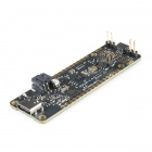
Board Layout
- QuickLogic EOS S3 MCU Platform
- ST micro LIS2DH12TR accelerometer
- SparkFun’s Qwiic connector
- Vesper’s VM3011 MEMS PDM microphone
- 16Mbit of on-board flash memory
- User button and RGB LED
- Hardware Reset button
- Powered from USB or a single Li-Po battery
- Integrated battery charger
- USB data signals tied to programmable logic
- IO signals break-routed into general purpose pinheads

IO Expansion Connectors EOS S3 MCU IO Map to QuickLogic Thing Plus

| EOS S3 MCU IO | QuickLogic Thing Plus Function | Additional Function | Expansion |
|---|---|---|---|
| IO_0 | I2C0 SCL | J9.11 | |
| IO_1 | I2C0 SDA | J9.12 | |
| IO_2 | IO | J6.7 | |
| IO_3 | Accelerometer LIS2DH12TR Interrupt | J9.10 | |
| IO_4 | IO | J8.8 | |
| IO_5 | IO | J8.9 | |
| IO_6 | User Button Input | J8.10 | |
| IO_7 | IO | J8.11 | |
| IO_8 | IO | J8.12 | |
| IO_10 | IO | J8.13 | |
| IO_11 | IO | J8.6 | |
| IO_12 | IO | J8.7 | |
| IO_13 | IO | J6.8 | |
| IO_14 | Serial Wire Debug CLK | J6.4 | |
| IO_15 | Serial Wire Debug DATA | J6.2 | |
| IO_16 | IO | SPI Peripheral CLK | J9.8 |
| IO_17 | IO | SPI Peripheral CIPO (input) | J9.7 |
| IO_18 | Blue LED | N/A | |
| IO_19 | IO | SPI Peripheral COPI | J9.6 |
| IO_20 | IO | SPI Peripheral CSn | J9.5 |
| IO_21 | Green LED | N/A | |
| IO_22 | Red LED | N/A | |
| IO_23 | IO | I2S Peripheral WCLK (Frame) | J8.3 |
| IO_24 | IO | I2S Peripheral DATA (dout) | J8.4 |
| IO_25 | IO | J6.9 | |
| IO_27 | IO | SPI Controller CS2 | J9.2 |
| IO_28 | PDM Data; to isolate, remove R28 | J8.1 | |
| IO_29 | PDM CKO | J8.2 | |
| IO_30 | IO | J6.10 | |
| IO_31 | IO | I2S Peripheral CLK (input) | J8.5 |
| IO_32 | IO | J9.3 | |
| IO_33 | IO | J9.4 | |
| IO_34 | SPI Controller CLK | J6.6 | |
| IO_36 | SPI Controller CIPO | J6.4 | |
| IO_38 | SPI Controller COPI (flash) | J6.5 | |
| IO_40 | IO | N/A | |
| IO_43 | IO | Interrupt Output to Host | J9.9 |
| IO_44 | IO | UART TX | J6.2 |
| IO_45 | IO | UART RX | J6.3 |
Connector J9
| J2 | EOS S3 MCU IO | BGA Pin# | Function |
|---|---|---|---|
| 1 | VBAT | ||
| 2 | 3.3V Circuit Enable | ||
| 3 | VBUS | ||
| 4 | IO_27 | HS | IO; SPI Controller CSn2 |
| 5 | IO_20 | G8 | SPI Peripheral SSn input; EOS S3 boot-strap |
| 6 | IO_19 | H8 | SPi Peripheral COPI input; EOS S3 boot-strap |
| 7 | IO_17 | D7 | SPI Peripheral CIPO output |
| 8 | IO_16 | E7 | SPI Peripheral CLK input |
| 9 | IO_43 | D1 | EOS S3 Interrupt Output |
| 10 | IO_3 | A2 | Accel Interrupt input |
| 11 | IO_0 | B1 | I2C0 SCL |
| 12 | IO_1 | C1 | I2C0 SDA |
Connector J6
| J6 | EOS S3 MCU IO | BGA Pin# | Function |
|---|---|---|---|
| 1 | Ground | ||
| 2 | IO_44 | E1 | S3 UART TX |
| 3 | IO_45 | G1 | S3 UART RX |
| 4 | IO_36 | H3 | SPI Controller CIPO input |
| 5 | IO_38 | E2 | SPI Controller COPI output |
| 6 | IO_34 | F3 | SPI Controller CLK output |
| 7 | IO_2 | A1 | IO |
| 8 | IO_13 | D6 | IO |
| 9 | IO_25 | F7 | IO |
| 10 | IO_30 | F4 | IO |
| 11 | ADC1 | C7 | ADC1 input |
| 12 | No Connect | ||
| 13 | Ground | ||
| 14 | No Connect | ||
| 15 | +3.3V | ||
| 16 | SYS_RSTn | F8 | EOS S3 HW reset input |
Connector J8
| J8 | EOS S3 MCU IO | BGA Pin# | Function |
|---|---|---|---|
| 1 | IO_28 | G5 | PDM microphone Data |
| 2 | IO_29 | F5 | PDM microphone CLK |
| 3 | IO_23 | H6 | I2S Peripheral WCLK Input |
| 4 | IO_24 | G6 | I2S Peripheral DATA output |
| 5 | IO_31 | G4 | I2S Peripheral CLK input |
| 6 | IO_11 | C5 | IO |
| 7 | IO_12 | B5 | IO |
| 8 | IO_4 | B2 | IO |
| 9 | IO_5 | C3 | IO |
| 10 | IO_6 | B3 | User button input |
| 11 | IO_7 | A3 | IO |
| 12 | IO_8 | C4 | IO |
| 13 | IO_10 | A4 | IO |
| 14 | IO_35 | F2 | IO |
| 15 | +3.3V | ||
| 16 | Ground | ||
| 17 | +3.3V | ||
| 18 | Ground |
Development Connector
EOS S3 MCU SWD Connector
| J7 | EOS S3 MCU IO | Function |
|---|---|---|
| 1 | +3.3V | |
| 2 | IO_15 | SWD_IO |
| 3 | Ground | |
| 4 | IO_14 | SWD_CLK |
| 5 | Ground | |
| 6 | No Connect | |
| 7 | No Connect | |
| 8 | No Connect | |
| 9 | Ground | |
| 10 | SYS_RSTn | Hardware Reset |
Boot-strap IO_19 & IO_20
- Install both shunts to use SWD Debugger for development
- Remove both shunts for boot-from-flash

Power
There are two ways to provide power to the QuickLogic Thing Plus: USB connector (J5) or Battery connector (J4). When both ports are connected at the same time, the USB power activates the battery charging circuit that provide charging current to the battery.
When using a rechargeable battery, the minimum input voltage will determine the maximum currents that the system needs to support. This is important when connecting additional peripherals to the QuickLogic Thing Plus that also requires connection to +3.3V for supplies.

The MCP73831 LiPo charger is set to ~212.76mA for the default charge rate. Before you plug a battery into the charger, you should be aware of your battery's capacity and the charge current supplied by the charger. To be safe*, you should keep the charge current at or below 1C of your battery. That means you should connect a LiPo battery that has a capacity of ~212.75mAh or higher to charge safely. For more information on the charge LED's status, check out the LiPo USB Charger breakout board for the MCP73831.
Connecting Additional Peripherals to the QuickLogic Thing Plus
QuickLogic Thing Plus supports direct connection to FeatherWing module (providing that the FeatherWing module has Stack Headers installed) via expansion connector J2 and J3. Refer to AdaFruit's web site for additional information on available FeatherWing modules.
Sensor with I2C Port
QuickLogic Thing Plus board supports connecting to sensor module with I2C peripheral interface via expansion connectors J2. QuickLogic Thing Plus I2C supports I2C Standard mode (100KHz) and Fast mode (400KHz). There is one I2C bus available; additional I2C IP can be implemented in EOS S3 FPGA.
- I2C0 bus: J2 pin 12 (SDA) and J2 pin 11 (SCL); the signals (SCL and SDA) are connected to 4.7KΩ pull-up resistor. This bus is shared with onboard I2Csensor, LIS2DH12TR (b0011000x).
Steps to connect external I2C sensors to QuickLogic Thing Plus board:
- Ground connection
- Power connection (+3.3V supplies); check supply voltage level meeting connecting module requirement
- Connect SCL and SDA signals; check IO level (> +3.0V IO only)
- Keep connecting wires as short as possible
- Configure the I2Caddress to avoid LIS2DH12TR assigned address (b0011000x)
- Check SCL and SDA rise time (< 1000 ns for Standard mode and < 300 ns for Fast mode)
Note: may need to use oscilloscope to validate the rise time for SCL and SDA to stay within rise time specification
Sensor with SPI Peripheral port
QuickLogic Thing Plus board supports connecting to sensor module with SPI peripheral interface via expansion connectors J6 and J9: SPI CONTROLLER CLK (J6 pin 6), SPI CONTROLLER CIPO (J6 pin 4), SPI CONTROLLER COPI (J6 pin 5) and SPI CONTROLLER CS2 (J9 pin 4). The maximum supported SPI clock frequency is 10MHz.
Steps to connect external SPI sensor to QuickLogic Thing Plus board:
- Ground connection
- Power connection (+3.3V supplies check supply voltage level meeting connecting module requirement
- Connect SPI CONTROLLER signals; check IO level (> +3.0V IO only)
- Keep connecting wires as short as possible
- Check signal quality using scope
PDM Microphones
Single PDM Microphone
The on-board PDM microphone (Vesper VM3011) is configured as left channel output (driving active data on falling edge of PDM CLK). QuickLogic Thing Plus supports external PDM microphone connection via expansion connector J8: PDM CLK (J8 pin 2) and PDM DATA (J8 pin 1).
Steps to connect one external PDM microphone to QuickLogic Thing Plus board:
- Ground connection
- Power connection (+3.3V supplies check supply voltage level meeting connecting module requirement
- Remove R28 (100Ω resistor)
- Connect PDM CLK and PDM DATA signals; check IO level (> +3.0V IO only)
- Keep connecting wires as short as possible
- PDM microphone is configured as right channel microphone; the L/R signal or Channel signal is connected to VDD
- Check signal quality using scope
Double PDM Microphone
To support two external PDM microphones configuration, it is required to disable the connection of the on-board PDM microphone.
QuickLogic Thing Plus supports external PDM microphone connection via expansion connector J8: PDM CLK (J8 pin 2) and PDM DATA (J8 pin 1).
Steps to connect two external PDM microphones to QuickLogic Thing Plus board:
- Ground connection
- Power connection (+3.3V supplies check supply voltage level meeting connecting module requirement
- Remove R28 (100Ω resistor)
- Connect PDM CLK and PDM DATA signals; check IO level (> +3.0V IO only)
- Keep connecting wires as short as possible; avoid star connection scheme (see figure below)
- Configure one PDM microphone as left channel and one PDM microphone as right channel
- Check signal quality using scope

Board Dimensions
The board is 2.75"x2.10". While the board uses the Thing Plus footprint, length of the board is slightly longer than other Thing Plus designs.

Hardware Assembly
To power, you will need to insert a USB cable to the board.

Getting Started
Running Pre-Loaded Program from Flash
The purpose of the pre-loaded program is to make it very fast and straightforward for a new user to verify the board is functioning correctly. While we do production testing on every QuickLogic Thing Plus before we ship, sometimes things happen during shipping or storage. Running this test takes less than a minute to do, requires no knowledge of the QuickLogic Thing Plus, and will give you peace of mind the QuickLogic Thing Plus is ready for you to start innovating freely.
- Make sure there is no shunt installed at J2 and J3; if there are shunts installed, remove the shunts; save the shunts for future firmware development
- Provide power to the QuickLogic Thing Plus using the Type-C USB cable; the power source can be either a PC or wall adapter. When there is power applied to the board, the LED flashes “white” for a short duration
- Press the “reset” button
- The LED flashes blue color for 5 seconds and then turns off
- Wait for 5 seconds
- On Windows 10 machine, open Device Manager to check for the assign COM port

- Launch PuTTY application and configure for Serial access and select “Open”.

8. Perform the followings in the PuTTY terminal:
a) Type: “diag” to bring up QuickLogic Thing Plus diagnostic menu
b) Type: “help” to bring up the menu of commands
c.) Type: “red”; the command shows red color for LED
d.) Type: “red”; the LED turns off the LED
e.) Try “green” and “blue” command


Download Binaries using JLink SWD
QuickLogic Thing Plus supports loading and testing stand-alone eFPGA design or eFPGA + M4 MCU design, using SWD standard tool such as Segger’s Jlink SWD or OCD. Below are the instructions for system with Windows 10 OS with Segger Jlink pod.
What you need
- Laptop or PC with Windows 10
- Segger Jlink pod and PC connecting USB cable
- Segger Jlink adapter to 10-pin connector and cable
- QuickLogic Thing Plus board and micro USB cable

Download stand-alone FPGA binaries instructions
- Disconnect QuickLogic Thing Plus power; if USB-to-Serial cable connected to the board, remove the connection from PC
- Install shunts at QuickLogic Thing Plus J2 and J3
- Connect micro USB cable from QuickLogic Thing Plus to PC
- Connect 10-pin cable to QuickLogic Thing Plus connector J6; check connector key for correct alignment
- Press reset button
- Open CMD console
- Type: “Jlink.exe -device cortex-m4 -If SWD -speed 4000 -commandFile "Jlink script"
Note: * Jlink.exe: Link commander – include reference to the location of executable * Jlink script: output file symbiflow for EOS S3 FPGA binaries * Refer to Jlink Commander for more additional information
Download FPGA binaries + M4 MCU binaries instructions
- Disconnect QuickLogic Thing Plus power; if USB-to-Serial cable connected to the board, remove the connection from PC
- Install shunts at QuickLogic Thing Plus J2 and J3
- Connect micro USB cable from QuickLogic Thing Plus to PC
- Connect 10-pin cable to QuickLogic Thing Plus connector J7; check connector key for correct alignment
- Press reset button
- Open CMD console (#1)
- Launch Jlink commander (i.e. type “Jlink.exe”) and follow the on-screen instructions to connect to QuickLogic Thing Plus M4 target
- Execute the followings in Link Commander console
- Type: “r” to reset the EOS S3
- Type: “loadbin qt_helloworldsw.bin 0x0”
- Type: “r”
- Open another CMD console (#2)
- Type: “Jlink.exe -device cortex-m4 -If SWD -speed 4000 -commandFile "Jlink script"
Note: * Jlink.exe: Link commander – include reference to the location of executable * Jlink script: Symbiflow’s output for EOS S3 FPGA binaries * Refer to Jlink Commander for more additional information * Return to console #1; type: “g”; the M4 binaries in M4 SRAM will start to run and the eFPGA is configured
Resources and Going Further
Now that you've successfully got your QuickLogic EOS S3 Thing Plus up and running, it's time to incorporate it into your own project!
For more information, check out the resources below:
- Schematic (PDF)
- Cadence Board File (BRD)
- Board Dimensions (JPG)
- Graphical Datasheet
- QuickLogic EOS E3
- Software
- Machine Learning
- TensorFlow Lite
- SensiML
- Real-time Operating Systems
- FPGA Tools
- Machine Learning
- GitHub Hardware Repo
- Product Showcase
Need some inspiration for your next project? Check out some of these related tutorials:
learn.sparkfun.com | CC BY-SA 3.0 | SparkFun Electronics | Niwot, Colorado