Qwiic ToF Imager - VL53L5CX Hookup Guide a learn.sparkfun.com tutorial
Available online at: http://sfe.io/t2002
Introduction
The Qwiic ToF Imager - VL53L5CX is here! This little breakout board is built around ST Electronics' VL53L5CX; a state of the art, Time-of-Flight (ToF), multizone ranging sensor enhancing the ST FlightSense product family. This chip integrates a SPAD array, physical infrared filters, and diffractive optical elements (DOE) to achieve the best ranging performance in various ambient lighting conditions with a range of cover glass materials.
Multizone distance measurements are possible up to 8x8 zones with a wide 63° diagonal FoV which can be reduced by software. Thanks to ST Histogram patented algorithms, the VL53L5CX is able to detect different objects within the FoV. The Histogram also provides immunity to cover glass crosstalk beyond 60 cm.
Ideal for 3D room mapping, obstacle detection for robotics, gesture recognition, IoT, laser-assisted autofocus, and AR/VR enhancement, the Qwiic connector on this sensor makes integration easy.

Required Materials
To follow along with this tutorial, you will need the following materials. You may not need everything though depending on what you have. Add it to your cart, read through the guide, and adjust the cart as necessary.
Suggested Reading
If you aren't familiar with the Qwiic system, we recommend reading here for an overview.
| Qwiic Connect System |
We would also recommend taking a look at the following tutorials if you aren't familiar with them.
How to Work with Jumper Pads and PCB Traces
Hookup Guide for the SparkFun Artemis Thing Plus
Hardware Overview
VL53L5CX
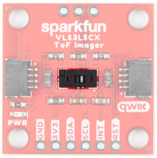
STMicroelectronics' VL53L5CX is a state of the art, time-of-flight (ToF), laser-ranging sensor with an 8x8 multizone range and a wide field of view. To see more details, refer to the datasheet.
Qwiic Connectors
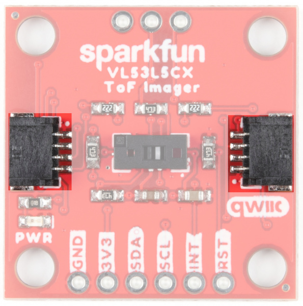
Our Qwiic Ecosystem makes sensors pretty much plug and play. There are two Qwiic connectors on either side of the Qwiic Air Velocity Sensor board to provide power and I2C connectivity simultaneously.
The unshifted I2C address of the board is 0x52.
Power
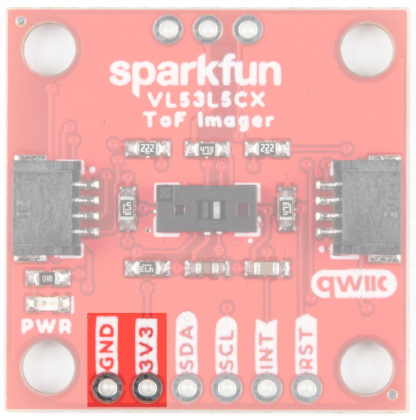
Ideally power will be supplied by the Qwiic connector, but if you wish to supply your own power, pins have been broken out along the bottom side of the board labeled 3V3 and GND. The input voltage range should be between 2.7-3.3V.
I2C
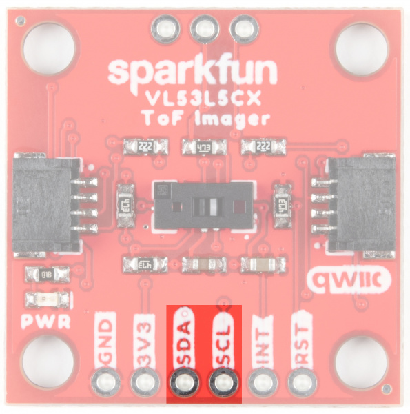
The I2C pins break out the functionality of the Qwiic connectors. Depending on your application, you can connect to these pins via the plated through holes for SDA and SCL.
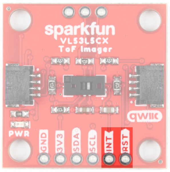
INT and RST
The interrupt pin is the interrupt output and defaults to an open-drain output. A 47 kΩ pull-up resistor to IOVDD is included.
The reset pin is the I2C interface reset pin and is active high. It is pulled to ground with a 47 kΩ resistor.
LP, VDDIO, & VDDA
LP is a low power enable pin. Drive this pin to logic 0 to disable the I2C comms to reduce power consumption. Drive this pin to logic 1 to enable I2C comms. This pin is typically only needed when you need to change the I2C address in multidevice systems. A 47 kΩ pull-up resistor to IOVDD is included so it can be left unconnected.
VDDIO/VDDA: These pins are used as an alternate power supply. By default, VDDIO and VDDA are tied together but by opening the PSU jumper they can be isolated. A user must then provide separate VDDIO and VDDA supplies. This is most applicable for users who want to use IO voltages (1.8, 2.8, or 3.3V) separate from AVDD voltages (2.8 or 3.3V) for maximum power reduction.

Jumpers
PSU
By default, VDDIO and VDDA are tied together. Cutting the PSU jumper will isolate the power rails. A user must then provide separate VDDIO and VDDA supplies. This is most applicable for users who want to use IO voltages (1.8, 2.8, or 3.3V) separate from AVDD voltages (2.8 or 3.3V) for maximum power reduction.

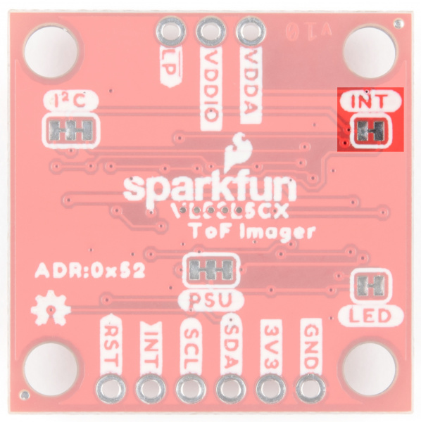
INT
Cut the INT jumper to remove the 47 kΩ pull-up resistor from the INT pin.
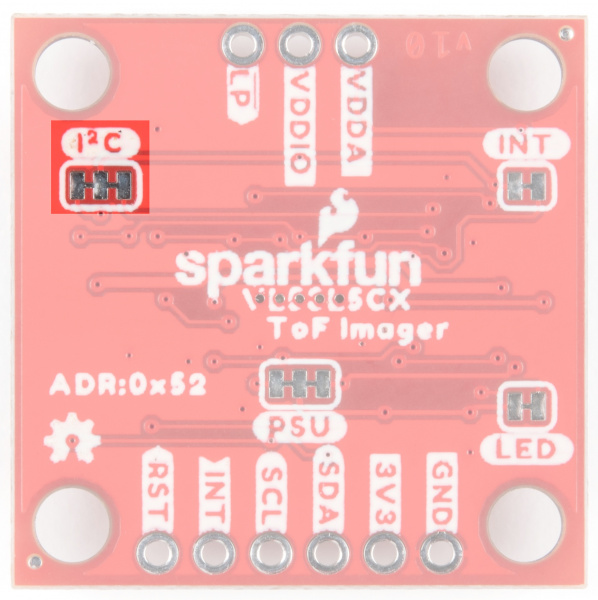
I2C
The SparkFun Qwiic ToF Imager Sensor has two 2.2 kΩ pull-up resistors attached to the I2C bus by default. If multiple sensors are connected to the bus with the pull-up resistors enabled the parallel equivalent resistance may create too strong of a pull-up for the bus to operate correctly. As a general rule of thumb, disable all but one pair of pull-up resistors if multiple devices are connected to the bus. If you need to disconnect the pull-up resistors they can be removed by cutting the traces on the corresponding jumper highlighted below.
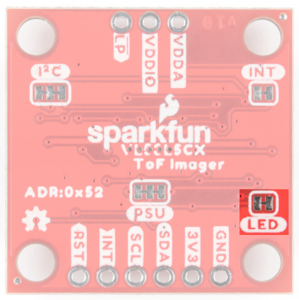
LED
If minimal power consumption is a concern, or you just don't want that Power LED on the front of the board to light up, go ahead and cut this jumper.
Board Outline
This sensor measures 1" x 1".

Hardware Hookup
Using the Qwiic system, assembling the hardware is simple. All you need to do is connect your VL53L5CX Imager Breakout to your chosen development board with a Qwiic cable or adapter cable. If Qwiic is not your thing, or if your dev board doesn't have one built in you can always solder directly to the I2C pins. If you are not using a Qwiic-enabled board, make sure your input voltage and logic are either running at 3.3V or you are shifting the logic level from whatever logic your controller runs at to 3.3V.

Software Setup and Programming
We've written a simple Arduino library to quickly get started reading data from the Qwiic ToF Imager. Install the library through the Arduino Library Manager tool by searching for "SparkFun VL53L5CX". Users who prefer to manually install it can get the library from the GitHub Repository or download the ZIP by clicking the button below:
Example1_DistanceArray
Hook up your ToF imager to your Artemis Thing Plus via the Qwiic cables, and click "File>Examples>SparkFun VL53L5CX Arduino Library>Example1_DistanceArray".

We'll assume that you have selected the board (in this case the SparkFun Artemis Thing Plus) and the correct COM port at this point. If you have the code open, hit the upload button. Otherwise, copy and paste the following into the Arduino IDE, make sure to select the correct board and COM port, and then upload:
language:c
/*
  Read an 8x8 array of distances from the VL53L5CX
  By: Nathan Seidle
  SparkFun Electronics
  Date: October 26, 2021
  License: MIT. See license file for more information but you can
  basically do whatever you want with this code.

  This example shows how to read all 64 distance readings at once.

  Feel like supporting our work? Buy a board from SparkFun!
  https://www.sparkfun.com/products/18642

*/

#include <Wire.h>

#include <SparkFun_VL53L5CX_Library.h> //http://librarymanager/All#SparkFun_VL53L5CX

SparkFun_VL53L5CX myImager;
VL53L5CX_ResultsData measurementData; // Result data class structure, 1356 byes of RAM

int imageResolution = 0; //Used to pretty print output
int imageWidth = 0; //Used to pretty print output

void setup()
{
  Serial.begin(115200);
  delay(1000);
  Serial.println("SparkFun VL53L5CX Imager Example");

  Wire.begin(); //This resets to 100kHz I2C

  Serial.println("Initializing sensor board. This can take up to 10s. Please wait.");
  if (myImager.begin() == false)
  {
    Serial.println(F("Sensor not found - check your wiring. Freezing"));
    while (1) ;
  }

  myImager.setResolution(8*8); //Enable all 64 pads

  imageResolution = myImager.getResolution(); //Query sensor for current resolution - either 4x4 or 8x8
  imageWidth = sqrt(imageResolution); //Calculate printing width

  myImager.startRanging();
}

void loop()
{
  //Poll sensor for new data
  if (myImager.isDataReady() == true)
  {
    if (myImager.getRangingData(&measurementData)) //Read distance data into array
    {
      //The ST library returns the data transposed from zone mapping shown in datasheet
      //Pretty-print data with increasing y, decreasing x to reflect reality
      for (int y = 0 ; y <= imageWidth * (imageWidth - 1) ; y += imageWidth)
      {
        for (int x = imageWidth - 1 ; x >= 0 ; x--)
        {
          Serial.print("\t");
          Serial.print(measurementData.distance_mm[x + y]);
        }
        Serial.println();
      }
      Serial.println();
    }
  }

  delay(5); //Small delay between polling
}
Open up your Serial Monitor, make sure the baud rate is set appropriately, and you should see something like the following:

Example2_FastStartup
Hook up your ToF imager to your Artemis Thing Plus via the Qwiic cables, and click "File>Examples>SparkFun VL53L5CX Arduino Library>Example2_FastStartup".
We'll assume that you have selected the board (in this case the SparkFun Artemis Thing Plus) and the correct COM port at this point. If you have the code open, hit the upload button. Otherwise, copy and paste the following into the Arduino IDE, make sure to select the correct board and COM port, and then upload:
language:c
/*
  Read an 8x8 array of distances from the VL53L5CX
  By: Nathan Seidle
  SparkFun Electronics
  Date: October 26, 2021
  License: MIT. See license file for more information but you can
  basically do whatever you want with this code.

  This example shows how to setup the I2C bus to minimize the amount
  of time taken to init the sensor.

  At each power on reset, a staggering 86,000 bytes of firmware have to be sent to the sensor.
  At 100kHz, this can take ~9.4s. By increasing the clock speed, we can cut this time down to ~1.4s.

  Two parameters can be tweaked:

    Clock speed: The VL53L5CX has a max bus speed of 400kHz but we have had success up to 1MHz.

    Max transfer size: The majority of Arduino platforms default to 32 bytes. If you are using one
    with a larger buffer (ESP32 is 128 bytes for example), this can help decrease transfer times a bit.

  Measurements:
    Default 100kHz clock and 32 byte transfer: 9.4s
    400kHz, 32 byte transfer: 2.8s
    400kHz, 128 byte transfer: 2.5s
    1MHz, 32 byte transfer: 1.65s
    1MHz, 128 byte transfer: 1.4s

  Feel like supporting our work? Buy a board from SparkFun!
  https://www.sparkfun.com/products/18642

*/

#include <Wire.h>

#include <SparkFun_VL53L5CX_Library.h> //http://librarymanager/All#SparkFun_VL53L5CX

SparkFun_VL53L5CX myImager;
VL53L5CX_ResultsData measurementData; // Result data class structure, 1356 byes of RAM

int imageResolution = 0; //Used to pretty print output
int imageWidth = 0; //Used to pretty print output

void setup()
{
  Serial.begin(115200);
  delay(1000);
  Serial.println("SparkFun VL53L5CX Imager Example");

  Wire.begin(); //This resets I2C bus to 100kHz
  Wire.setClock(400000); //Sensor has max I2C freq of 400kHz
  //Wire.setClock(1000000); //Run sensor out of spec

  //myImager.setWireMaxPacketSize(128); //Increase default from 32 bytes to 128 - not supported on all platforms

  Serial.println("Initializing sensor board. This can take up to 10s. Please wait.");

  //Time how long it takes to transfer firmware to sensor
  long startTime = millis();
  bool startup = myImager.begin();
  long stopTime = millis();

  if (startup == false)
  {
    Serial.println(F("Sensor not found - check your wiring. Freezing"));
    while (1) ;
  }

  Serial.print("Firmware transfer time: ");
  float timeTaken = (stopTime - startTime) / 1000.0;
  Serial.print(timeTaken, 3);
  Serial.println("s");

  myImager.setResolution(8*8); //Enable all 64 pads

  imageResolution = myImager.getResolution(); //Query sensor for current resolution - either 4x4 or 8x8
  imageWidth = sqrt(imageResolution); //Calculate printing width

  myImager.startRanging();
}

void loop()
{
  //Poll sensor for new data
  if (myImager.isDataReady() == true)
  {
    if (myImager.getRangingData(&measurementData)) //Read distance data into array
    {
      //The ST library returns the data transposed from zone mapping shown in datasheet
      //Pretty-print data with increasing y, decreasing x to reflect reality
      for (int y = 0 ; y <= imageWidth * (imageWidth - 1) ; y += imageWidth)
      {
        for (int x = imageWidth - 1 ; x >= 0 ; x--)
        {
          Serial.print("\t");
          Serial.print(measurementData.distance_mm[x + y]);
        }
        Serial.println();
      }
      Serial.println();
    }
  }

  delay(5); //Small delay between polling
}
Open up your Serial Monitor, make sure the baud rate is set appropriately, and you should see something like the following:

Example3_SetFrequency
Hook up your ToF imager to your Artemis Thing Plus via the Qwiic cables, and click "File>Examples>SparkFun VL53L5CX Arduino Library>Example3_SetFrequency".
We'll assume that you have selected the board (in this case the SparkFun Artemis Thing Plus) and the correct COM port at this point. If you have the code open, hit the upload button. Otherwise, copy and paste the following into the Arduino IDE, make sure to select the correct board and COM port, and then upload:
language:c
/*
  Read an 8x8 array of distances from the VL53L5CX
  By: Nathan Seidle
  SparkFun Electronics
  Date: October 26, 2021
  License: MIT. See license file for more information but you can
  basically do whatever you want with this code.

  This example shows how to increase output frequency.

  Default is 1Hz.
  Using 4x4, min frequency is 1Hz and max is 60Hz
  Using 8x8, min frequency is 1Hz and max is 15Hz

  Feel like supporting our work? Buy a board from SparkFun!
  https://www.sparkfun.com/products/18642

*/

#include <Wire.h>

#include <SparkFun_VL53L5CX_Library.h> //http://librarymanager/All#SparkFun_VL53L5CX

SparkFun_VL53L5CX myImager;
VL53L5CX_ResultsData measurementData; // Result data class structure, 1356 byes of RAM

int imageResolution = 0; //Used to pretty print output
int imageWidth = 0; //Used to pretty print output

void setup()
{
  Serial.begin(115200);
  delay(1000);
  Serial.println("SparkFun VL53L5CX Imager Example");

  Wire.begin(); //This resets I2C bus to 100kHz
  Wire.setClock(400000); //Sensor has max I2C freq of 400kHz

  Serial.println("Initializing sensor board. This can take up to 10s. Please wait.");
  if (myImager.begin() == false)
  {
    Serial.println(F("Sensor not found - check your wiring. Freezing"));
    while (1) ;
  }

  myImager.setResolution(8 * 8); //Enable all 64 pads

  imageResolution = myImager.getResolution(); //Query sensor for current resolution - either 4x4 or 8x8
  imageWidth = sqrt(imageResolution); //Calculate printing width

  //Using 4x4, min frequency is 1Hz and max is 60Hz
  //Using 8x8, min frequency is 1Hz and max is 15Hz
  bool response = myImager.setRangingFrequency(15);
  if (response == true)
  {
    int frequency = myImager.getRangingFrequency();
    if (frequency > 0)
    {
      Serial.print("Ranging frequency set to ");
      Serial.print(frequency);
      Serial.println(" Hz.");
    }
    else
      Serial.println(F("Error recovering ranging frequency."));
  }
  else
  {
    Serial.println(F("Cannot set ranging frequency requested. Freezing..."));
    while (1) ;
  }

  myImager.startRanging();
}

void loop()
{
  //Poll sensor for new data
  if (myImager.isDataReady() == true)
  {
    if (myImager.getRangingData(&measurementData)) //Read distance data into array
    {
      //The ST library returns the data transposed from zone mapping shown in datasheet
      //Pretty-print data with increasing y, decreasing x to reflect reality
      for (int y = 0 ; y <= imageWidth * (imageWidth - 1) ; y += imageWidth)
      {
        for (int x = imageWidth - 1 ; x >= 0 ; x--)
        {
          Serial.print("\t");
          Serial.print(measurementData.distance_mm[x + y]);
        }
        Serial.println();
      }
      Serial.println();
    }
  }

  delay(5); //Small delay between polling
}
Open up your Serial Monitor, make sure the baud rate is set appropriately, and you should see something like the following:

Troubleshooting
If your product is not working as you expected or you need technical assistance or information, head on over to the SparkFun Technical Assistance page for some initial troubleshooting.
If you don't find what you need there, the SparkFun Forums are a great place to find and ask for help. If this is your first visit, you'll need to create a Forum Account to search product forums and post questions.
Resources and Going Further
Now that you've successfully got your Qwiic ToF sensor up and running, it's time to incorporate it into your own project!
For more information, check out the resources below:
Need some inspiration for your next project? Check out some of these related tutorials:
Qwiic Real Time Clock Module (RV-1805) Hookup Guide
RedBoard Qwiic Hookup Guide
Keyboard Shortcut, Qwiic Keypad
SparkFun Photodetector (MAX30101) Hookup Guide
learn.sparkfun.com | CC BY-SA 3.0 | SparkFun Electronics | Niwot, Colorado