GNSS Correction Data Receiver (NEO-D9S) Hookup Guide a learn.sparkfun.com tutorial
Available online at: http://sfe.io/t2352
Introduction
The SparkFun GNSS Correction Data Receiver - NEO-D9S is a satellite data receiver for L-band correction broadcast. It can be configured for use with a variety of correction services including u-blox's PointPerfect satellite GNSS augmentation service, which provides homogenous coverage in contiguous USA and Europe. With a clear view of the sky, especially a clear view to the South, it decodes the satellite transmission and outputs a correction stream, enabling a multi-band high precision GNSS receiver (such as the u-blox ZED-F9P) to reach accuracies down to centimeter-level positioning without needing a separate RTK or NTRIP correction!

Required Materials
To follow along with this tutorial, you will need the following materials. You may not need everything though depending on what you have. Add it to your cart, read through the guide, and adjust the cart as necessary.
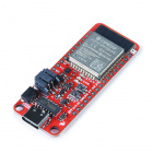
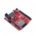
Arduino Microcontroller
We recommend an Arduino microcontroller with the ability to connect to WiFi. This is useful for those users taking advantage of both the ThingStream PointPerfect Location-as-a-Service over L-Band Satellite and Internet Protocol (IP). The following boards with the ESP32 WROOM module can work.
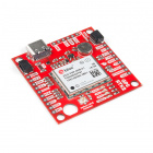
High Precision GNSS (HPG) Module
Along with the NEO-D9S, you will need a high precision GNSS (HPG) module from u-blox. As of the writing of his tutorial, the GNSS correction data receiver works for the ZED-F9P module. You will need to make sure that it has the latest firmware when using the modules together.
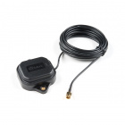
Antennae and Cables
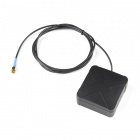
For the ZED-F9P, you will need a multi-band antenna to take advantage of the the L1 and L2 bands. For the NEO-D9S, you will need a L-band antenna. While the GNSS Multi-band L1/L2 Surveying Antenna (TNC) TOP106 was designed for L1 and L2, we found that it was able to pick up the correction data tuned to a frequency within the L-band (1556.29MHz in the US and 1545.26MHz in EU). Make sure to also pick up the TNC to SMA male interface cable and if necessary, an additional SMA extension cable or u.FL to SMA interface cable for the ZED-F9P breakout boards populated with the u.FL connector.
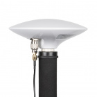
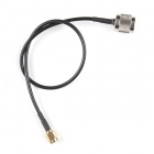
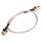
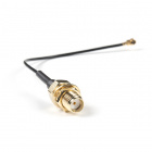
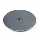
You could also use the u-blox or MagmaX2 multi-band antenna for the ZED-F9P and NEO-D9S. However, you would also need the ground plate. Again, while they were designed for L1 and L2, we found that it was also able to pick up the correction data tuned to a frequency within the L-band. You may also need an additional u.FL to SMA interface cable for ZED-F9P breakout boards populated with the u.FL connector.
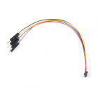
Qwiic Cables
For those that want to take advantage of the Qwiic enabled devices, you'll want to grab a Qwiic cable between each board.


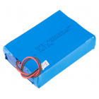
LiPo Battery
A single-cell Lithium-ion battery can be connected to the ESP32 IoT RedBoard's JST connector. In turn, this will power the NEO-D9S and ZED-F9P for portability.


Tools
Depending on your setup, you may need a soldering iron, solder, and general soldering accessories for a secure connection when using the plated through holes.


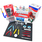

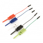
Prototyping Accessories
Depending on your setup, you may want to use IC hooks for a temporary connection. However, you will want to solder header pins to connect devices to the plated through holes for a secure connection.


You Will Also Need
You will need access to dynamic keys to decrypt the correct data sent from an L-band satellite. Users will need to purchase a pricing plan with the ThingStream PointPerfect Location-as-a-Service over L-Band Satellite.
As stated on the coverage map from u-blox, the service includes homogeneous coverage in the contiguous USA and Europe This includes up to 12 nautical miles (roughly 22 kilometers) off coastlines. Make sure to check back on u-blox's website to see if there is additional coverage in your region. Note that they recently updated the coverage to support South Korea. However, the Arduino Library has not been updated to include the frequency in South Korea. There are additional regions under consideration for the future but they have not been included yet.

- 1: Contiguous USA Operational
- All states, excluding Alaska, Hawaii, and offshore US territories
- 2: Europe Operational
- Albania, Andorra, Austria, Belgium, Bosnia and Herzegovina, Bulgaria, Croatia, Czech Republic, Denmark, Estonia, Finland, France, Germany, Holy see, Hungary, Ireland, Italy, Latvia, Liechtenstein, Lithuania, Luxembourg, Monaco, Montenegro, Netherlands, Norway, Poland, Portugal, Romania, San Marino, Serbia, Slovakia, Slovenia, Spain, Sweden, Switzerland, UK.
Excluding Sardinia and Corsica.
Suggested Reading
If you aren't familiar with the Qwiic system, we recommend reading here for an overview.
| Qwiic Connect System |
We would also recommend taking a look at the following tutorials if you aren't familiar with them.
GPS Basics
Serial Peripheral Interface (SPI)
How to Work with Jumper Pads and PCB Traces
What is GPS RTK?
Getting Started with U-Center for u-blox
GPS-RTK2 Hookup Guide
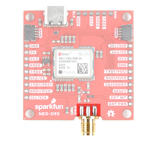
Hardware Overview
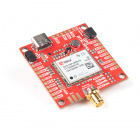
The NEO-D9S-00B is a satellite data receiver for L-band correction broadcast, which can be configured for use with a variety of correction services. It decodes the satellite transmission and outputs a correction stream, enabling a high precision GNSS receiver to reach accuracies down to centimeter level! In this section, we'll highlight important parts of the board. For more information about the NEO-D9S, check out the Resources and Going Further for more information.
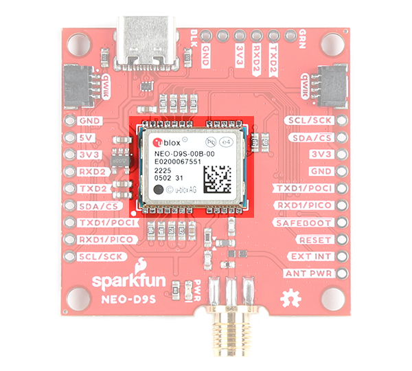
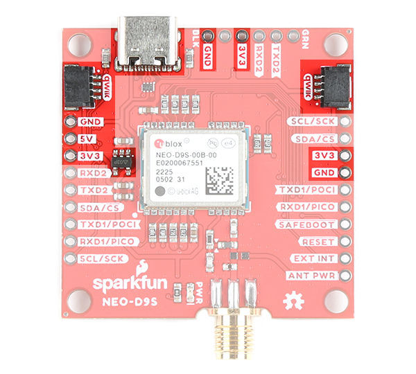
Power
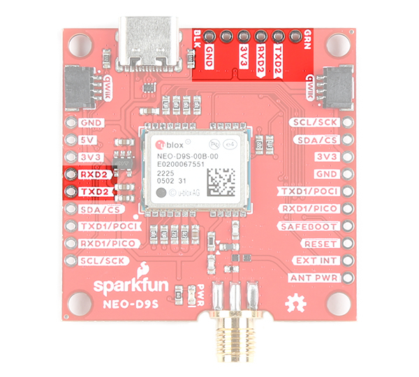
Power for this board is 3.3V and we have provided multiple power options. This first and most obvious is the USB-C connector. Secondly, are the Qwiic Connectors on the left and right of the board for ground and 3.3V. Thirdly, there is a 5V pin on the PTH header along the left side of the board that is regulated down to 3.3V with the 3.3V/600mA AP2112K voltage regulator (as indicated with the 5-pin component next to the 3V3 pin). Make sure that power you provide to this pin does not exceed 6 volts. Just below the 5V pin is a 3V3 pin that should only be provided a clean 3.3V power signal. 3V3 are also broken out on the USB-to-serial port and on the other side of the board. GND is also provided near each power pin.
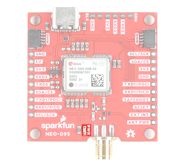
LED
There is one power LED labeled as PWR. The LED will illuminate when 3.3V is activated. This can be disabled by cutting the jumper on the back of the board labeled as "PWR" as well.
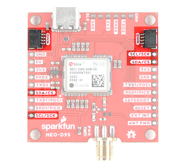
Qwiic and I2C
There are two pins labeled SDA and SCL which indicates the I2C data lines. Similarly, you can use either of the Qwiic connectors to provide power and utilize I2C. The Qwiic ecosystem is made for fast prototyping by removing the need for soldering. All you need to do is plug a Qwiic cable into the Qwiic connector and voila!
SPI
There are four pins that are labeled with their corresponding SPI functionality. These pins are broken out on both sides of the board. As mentioned in the jumpers section, you'll need to close the SPI jumper on the underside to enable SPI.
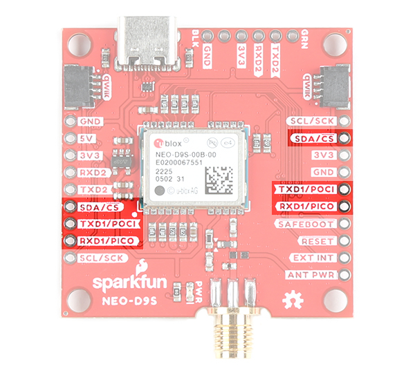
UART
There are two pins labeled as TXD1/POCI and RXD1/PICO. The UART pins are shared with the SPI pins. By default, the UART interface is enabled. Be sure that the SPI jumper on the back of the board is open.
- TXD1/POCI = TX out from NEO-D9S
- RXD1/PICO = RX into NEO-D9S
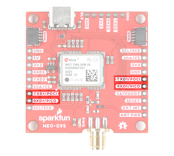
There is also a second UART port. You can connect this to a u-blox F9 module that supports correction data output from the NEO-D9S. The datasheet indicates that you could potentially use any high precision GNSS receiver from the u-blox F9 platform as denoted as the ZED-F9X, where the "X" indicates different variant. Make sure to check the latest u-blox F9 product Integration Manual for more information on whether the correction data is supported with the respective module
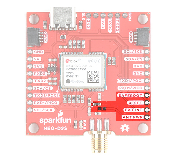
Broken Out Pins
There are four other pins broken out:
- SAFEBOOT: The safeboot pin (
SAFEBOOT) is used to start up the IC in safe boot mode, this could be useful if you somehow manage to corrupt the module's Flash memory. - RESET: The reset pin (
RESET) resets the chip. - EXT INT: The interrupt pin (
EXT INT) can be used to wake the chip from power save mode. - ANT PWR: The antenna power pin (
ANT PWR) is available for advanced users that want to power their L-band 3.3V active antenna with an external power source.- Isolate VCC_RF: You will need to isolate the VCC_RF. Users will need to make sure to cut the trace between the two arrows (i.e. ▶ ◀) to disable the VCC_RF antenna power. You can also shift the surface mount component that connects to the trace by moving it so that it does not connect to the SMA connector.
- Install SMD Component: You will then need to populate the board where L1 is located (i.e. the pads that are not currently populated and connects to the ANT PWR PTH) with a 0603 part with impedance >500 Ohms at 1.5GHz.
- Inject Power: When ready, connect a clean DC power supply voltage between ANT PWR and GND.
Jumpers
If you flip the board over, you will notice a few jumper pads. For more information on modifying the jumpers, check out our tutorial on working with jumper pads and PCB traces.
- SHLD: This jumper connects the USB Type C connector's shield pin to GND. Cut this to isolate the USB Type C connector's shield pin.
- 3V3: This jumper connects 3.3V to the UART2 port. By default, this is closed and will provide power to the your GNSS receiver. Cut this jumper if you are connecting a 3.3V USB-to-Serial converter with its own power source, or if the GNSS receiver is being powered with its own power source.
- I2C: This three way jumper labeled
I2Cwill connect to two pull-up resistors to the I2C data lines when closed. For users with that do not have pull-up reesistors attached to the I2C lines on their microcontroller, make sure to close the jumpers with a little solder blob. - PWR: The jumper labeled
PWRconnects to the power LED. If you cut this trace, it will disconnect the Power LED. - SPI: The jumper labeled
SPIenables the SPI data bus, thus disabling the UART functions on those lines. This also disables I2C interface.
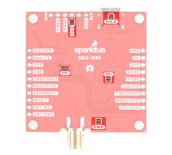
SMA Connector
The board is equipped with a SMA connector. You will need an active antenna that can receive signals from an L-Band satellite between 1525.0 MHz to 1559.0 MHz as stated in the datasheet. The specific frequency between the L-Band that the NEO-D9S uses depends on your region and service provider. Make sure to check the antenna's datasheet, region, and service provider for more information.
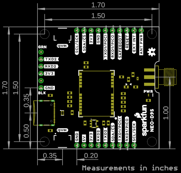
Board Dimensions
The board dimensions are 1.70"x1.70". This does not include the dimensions for the SMA connector and USB Type C connector. There are four mounting holes by each corner of the board.
Hardware Hookup
To add GNSS correction data to your high precision GNSS receiver like the ZED-F9P, you can connect any of the serial ports between the two boards. If you are using SPI to connect, just make sure to enable the SPI port by adding a solder jumper to the SPI jumper pads. For an embedded application, we recommend adding an ESP32 to the setup. In addition to the Thingstream PointPerfect over L-band satellite, will also allow you to use the Thingstream PointPerfect SPARTN encryption keys directly from u-blox's Thingstream IoT Internet Protocol (IP) service using MQTT.
I2C via Qwiic
Below is one example to connect using the I2C port and Qwiic. Simply insert a Qwiic cable between the ZED-F9P, NEO-D9S, and Arduino microcontroller's Qwiic connectors. Plug in a compatible antenna with SMA connector to the ZED-F9P and NEO-D9S board. For the ZED-F9P, you will need the multiband antenna that is capable of receiving L1/L2 bands. For boards that have a u.FL connector, make sure use a u.FL to SMA adapter cable. For the NEO-D9S, you will need to attach an L-Band antenna. Secure the connection on both antennas using the hex nut until it is finger-tight. For power, we will use a USB-C cable to power the ESP32 development board. You can also use this cable to connect each breakout to your computer when using the u-blox u-center software.

I2C and UART2 Ports via PTH
For those that prefer a PTH connection, you could connect using male header pins, 2-pin jumpers, F/F jumper wires, and M/F jumper wires. In this case, the ZED-F9P and NEO-D9S breakout boards were connected using the male header pins and 2-pin jumpers. The Arduino microcontroller was connected using a Qwiic cable. Of course, you will still need to plug in a compatible antenna with SMA connector to the ZED-F9P and NEO-D9S board. For the ZED-F9P, you will need the multiband antenna that is capable of receiving L1/L2 bands. For boards that have a u.FL connector, make sure use a u.FL to SMA adapter cable. For the NEO-D9S, you will need to attach an L-Band antenna. Secure the connection using the hex nut until it is finger-tight. For power, we will use a USB-C cable to power the ESP32 development board. You can also use this cable to connect each breakout to your computer when using the u-blox u-center software.

u-blox Firmware Update
UBX-RXM-PMP). At the time of writing, the ZED-F9P supports the SPARTN formatted corrections sent by the NEO-D9S with FW 1.00 HPG 1.30 and above. We tested using the latest FW 1.00 HPG 1.32+. Check your module's firmware release notes if you are unsure if the version number supports the SPARTN formatted corrections.
We recommend checking the firmware on your high precision GNSS (HPG) module (in this case, the ZED-F9P). If the firmware is old, you will need to upgrade the firmware on the HPG module.
How to Upgrade Firmware of a u-blox GNSS Receiver
March 26, 2021
You can download the latest firmware from u-blox. Below is a link to the ZED-F9P module's product page. Click the "Documentation & resources" tab and look for the latest firmware under the section Firmware Update. You may need to hit the Load more button a few times before you can see the firmware.
UBX-RXM-PMP). Make sure to check the associated datasheets for your high precision GNSS module for more information.
u-Blox Thingstream Services
There are three key steps to be able to achieve centimeter positioning accuracy using the ZED-F9P and NEO-D9S.
- Register with u-blox Thingstream and sign up for a PointPerfect L-band plan (data stream)
- Configure the NEO-D9S to receive the u-blox PointPerfect correction data stream
- Configure the ZED-F9P with encryption key(s) so it can decrypt and use the correction data
By default, the ZED-F9P is configured such that the correction data is passed from the NEO to the ZED using the UART2 interface. However, it is also possible to read the correction data from the NEO and push (write) it to the ZED using I2C. We just need to configure the modules so that the I2C port is enabled and set the protocol.
Thingstream and PointPerfect Services
The NEO-D9S was designed to receive correction data from an L-band satellite and push it to a high precision GNSS module like the ZED-F9P. You will need to use u-blox Thingstream and PointPerfect service to provide dynamic keys in order to decrypt the correction data.
 |
Thingstream is u-blox service delivery platform for IoT Communication-as-a-Service, IoT Security-as-a-Service and IoT Location-as-a-Service.
 |
PointPerfect is u-blox GNSS augmentation service which is designed to provide high-precision GNSS corrections to suitable receivers to provide decimeter-level location accuracy. The following webinar from u-blox has an excellent explanation of the service and how the system works.
PointPerfect data is delivered through Thingstream. The first step is to register with Thingstream and then request an L-Band plan:

You can find the current pricing on u-blox portal. Select IoT Location-as-a-Service and then PointPerfect.
You may need to contact u-blox first, to enable the option to purchase an L-Band plan through your Thingstream account.
The PointPerfect L-band plan provides unlimited access to the L-band satellite correction data stream (via the NEO-D9S).
If you have an internet connection, you can also receive PointPerfect corrections via IP (MQTT). The PointPerfect L-band and IP plan may be a better choice if you think you may want to receive correction data via both satellite and Internet.
Once L-band permissions are enabled on your Thingstream account, you will be able to add a new L-band Location Thing and view its credentials:
- Login to Thingstream
- Select Location Services and then Location Things
- The Add Location Thing button (top right) will allow you to select and activate an L-Band plan
- Once your L-band plan is active, you will be able to monitor your Activity and view your Credentials via the appropriate tabs
u-blox have written a comprehensive application note which describes in detail: the configuration of both NEO and ZED; and how to interpret the expiry date for the L-band encryption keys. In the following sections, we describe how to configure the NEO and ZED using our u-blox GNSS Arduino Library.
Installing the Arduino Library
- Installing the Arduino IDE
- Installing an Arduino Library
- Installing Board Definitions in the Arduino IDE
If you've never connected an CH340 device to your computer before, you may need to install drivers for the USB-to-serial converter. Check out our section on How to Install CH340 Drivers" for help with the installation.
All of our u-blox based GPS boards share the same library: the breakout board, their predeccesors and the higher precisionu-blox cousins. The SparkFun u-blox Arduino library can be downloaded with the Arduino library manager by searching 'SparkFun u-blox GNSS' or you can grab the zip here from the GitHub repository to manually install. Once calibrated, you can take advantage of the examples for the NEO-D9S.
Arduino Library Overview
We will be highlighting a few parts of the SparkFun u-blox Arduino GNSS Library below for the NEO-D9S and the ZED-F9P.
NEO-D9S Configuration
The first step is to declare the SFE_UBLOX_GNSS object. Like most Arduino sketches, this is done at a global scope (after the include file declaration), not within the setup() or loop() functions.
language:c
#include <SparkFun_u-blox_GNSS_Arduino_Library.h> //http://librarymanager/All#SparkFun_u-blox_GNSS
SFE_UBLOX_GNSS myLBand; // NEO-D9S
Within setup() we then need to start (initialize) communiation with the NEO-D9S. The NEO-D9S has a default I2C address of 0x43 and so we need to provide that when calling the begin method:
langauage:c
  Wire.begin(); //Start I2C

  while (myLBand.begin(Wire, 0x43) == false) //Connect to the u-blox NEO-D9S using Wire port. The D9S default I2C address is 0x43 (not 0x42)
  {
    Serial.println(F("u-blox NEO-D9S not detected at default I2C address. Please check wiring."));
    delay(2000);
  }
  Serial.println(F("u-blox NEO-D9S connected"));
The NEO-D9S needs to be configured so it can receive the PointPerfect correction stream. The configuration items are:
| Configuration item | Default value |
|---|---|
| CFG-PMP-CENTER_FREQUENCY | 1539812500 Hz |
| CFG-PMP-SEARCH_WINDOW | 2200 Hz |
| CFG-PMP-USE_SERVICE_ID | 1 (true) |
| CFG-PMP-SERVICE_ID | 50821 |
| CFG-PMP-DATA_RATE | 2400 (B2400) bps |
| CFG-PMP-USE_DESCRAMBLER | 1 (true) |
| CFG-PMP-DESCRAMBLER_INIT | 23560 |
| CFG-PMP-USE_PRESCRAMBLING | 0 (false) |
| CFG-PMP-UNIQUE_WORD | 0xe15ae893e15ae893 |
The centre frequency varies depending on which satellite is broadcasting corrections for your geographical area. The frequency for the USA is different to that for Europe:
The up-to-date frequencies are distributed via the MQTT /pp/frequencies/Lb topic. At the time of writing, they are (in MHz):
language:c
{
  "frequencies": {
    "us": {
      "current": {
        "value": "1556.29"
      }
    },
    "eu": {
      "current": {
        "value": "1545.26"
      }
    }
  }
}
We can add those to the code as follows:
language:c
const uint32_t myLBandFreq = 1556290000; // Uncomment this line to use the US SPARTN 1.8 service
//const uint32_t myLBandFreq = 1545260000; // Uncomment this line to use the EU SPARTN 1.8 service
The code to configure the NEO-D9S is as follows. Note that the UBLOX_CFG_PMP_USE_SERVICE_ID, UBLOX_CFG_PMP_SERVICE_ID and UBLOX_CFG_PMP_DESCRAMBLER_INIT also need to be changed.
language:c
  uint8_t ok = myLBand.setVal32(UBLOX_CFG_PMP_CENTER_FREQUENCY,   myLBandFreq); // Default 1539812500 Hz
  if (ok) ok = myLBand.setVal16(UBLOX_CFG_PMP_SEARCH_WINDOW,      2200);        // Default 2200 Hz
  if (ok) ok = myLBand.setVal8(UBLOX_CFG_PMP_USE_SERVICE_ID,      0);           // Default 1
  if (ok) ok = myLBand.setVal16(UBLOX_CFG_PMP_SERVICE_ID,         21845);       // Default 50821
  if (ok) ok = myLBand.setVal16(UBLOX_CFG_PMP_DATA_RATE,          2400);        // Default 2400 bps
  if (ok) ok = myLBand.setVal8(UBLOX_CFG_PMP_USE_DESCRAMBLER,     1);           // Default 1
  if (ok) ok = myLBand.setVal16(UBLOX_CFG_PMP_DESCRAMBLER_INIT,   26969);       // Default 23560
  if (ok) ok = myLBand.setVal8(UBLOX_CFG_PMP_USE_PRESCRAMBLING,   0);           // Default 0
  if (ok) ok = myLBand.setVal64(UBLOX_CFG_PMP_UNIQUE_WORD,        16238547128276412563ull); // 0xE15AE893E15AE893
Finally, we need to ensure that the UART2 port is set correctly. We need to:
- Change the baud rate to 38400 - to match the ZED-F9P's baud rate
- Ensure that the UBX protocol is enabled for output on UART2
- Enable the RXM PMP message on UART2
- The RXM PMP message contains the SPARTN correction data in UBX format
- Perform a restart (software reset) so that the NEO-D9S starts using the new configuration items
language:c
  if (ok) ok = myLBand.setVal32(UBLOX_CFG_UART2_BAUDRATE,         38400); // match baudrate with ZED default
  if (ok) ok = myLBand.setVal(UBLOX_CFG_UART2OUTPROT_UBX,         1);     // Enable UBX output on UART2
  if (ok) ok = myLBand.setVal(UBLOX_CFG_MSGOUT_UBX_RXM_PMP_UART2, 1);     // Output UBX-RXM-PMP on UART2

  Serial.print(F("L-Band configuration: "));
  if (ok)
    Serial.println(F("OK"));
  else
    Serial.println(F("NOT OK!"));

  myLBand.softwareResetGNSSOnly(); // Do a restart
Once the NEO-D9S has aquired the signal from the satellite, it will start outputting PMP correction messages to the ZED-F9P on UART2.
ZED-F9P Configuration
We need to declare a second SFE_UBLOX_GNSS object for the ZED-F9P. Again, this is done at a global scope (after the include file declaration), not within the setup() or loop() functions.
language:c
SFE_UBLOX_GNSS myGNSS; // ZED-F9P
Within setup() we need to start (initialize) communication with the ZED-F9P:
language:c
  while (myGNSS.begin() == false) //Connect to the u-blox module using Wire port and the default I2C address (0x42)
  {
    Serial.println(F("u-blox GNSS module not detected at default I2C address. Please check wiring."));
    delay(2000);
  }
  Serial.println(F("u-blox GNSS module connected"));
We then need to:
- Make sure the ZED-F9P's UART2 port is configured to accept the PMP correction data
- Tell the ZED-F9P to use FIXED carrier solutions when possible (this is the default setting)
- Tell the ZED-F9P to accept L-band PMP as a correction source
language:c
          ok = myGNSS.setPortInput(COM_PORT_UART2, COM_TYPE_UBX | COM_TYPE_NMEA | COM_TYPE_SPARTN); //Be sure SPARTN input is enabled
  if (ok) ok = myGNSS.setDGNSSConfiguration(SFE_UBLOX_DGNSS_MODE_FIXED); // Set the differential mode - ambiguities are fixed whenever possible
  if (ok) ok = myGNSS.setVal8(UBLOX_CFG_SPARTN_USE_SOURCE, 1); // use LBAND PMP message
The final piece of the puzzle is to provide the ZED-F9P with the keys it needs to decrypt the encrypted SPARTN (PMP) corrections.
The ZED-F9P can hold two dynamic keys: the current key; and the next key. We also need to tell it when each key is valid from, so it knows when to switch to the next key.
You can find the current and next keys in the Location Services \ Location Things \ Thing Details \ Credentials tab in Thingstream:

The ZED-F9P actually needs to know when the keys are valid from, rather than when they expire. Each key is walid for four weeks, so we need to work backwards 4 weeks from the expiry date.
The current key expires at midnight (UTC) at the end of Friday September 23rd. This means it became valid 4 weeks earlier at midnight (UTC) on August 27th:

Using the website recommended in the u-blox Application Note:
we can see that the key became valid during GPS week 2224, at time-of-week 518400.
We can use the Arduino Library setDynamicSPARTNKey method to configure a single key:
language:c
  if (ok) ok = myGNSS.setDynamicSPARTNKey(16, 2224, 518400, "500--------------------------177");

  Serial.print(F("GNSS: configuration "));
  if (ok)
    Serial.println(F("OK"));
  else
    Serial.println(F("NOT OK!"));
Alternately, we can set both the current key and the next key together using setDynamicSPARTNKeys. The next key becomes valid during GPS week 2228:
language:c
  if (ok) ok = myGNSS.setDynamicSPARTNKeys(16, 2224, 518400, "500--------------------------177", 16, 2228, 518400, "582--------------------------a7d");
The keys can also be retrieved using MQTT. We have an Arduino Library example which shows how to retrieve the keys from the L-band + IP key distribution topic /pp/ubx/0236/Lb. That topic provides the keys in UBX (binary) format, ready to be pushed to the ZED.
The keys are also available in human-readable JSON format from the MQTT topic /pp/key/Lb . But note that that topic provides the valid from in Unix epoch format, in milliseconds, excluding the 18 leap seconds since GPS time started!
language:c
{
  "dynamickeys": {
    "current": {
      "start": "1661558382000",
      "duration": "2419199999",
      "value": "500--------------------------177"
    },
    "next": {
      "start": "1663977582000",
      "duration": "2419199999",
      "value": "582--------------------------a7d"
    }
  }
}
Example 30: NEO-D9S
From the menu, select the following: File>Examples>Examples from Custom Libraries | SparkFun u-blox GNSS Arduino Library>Example30_NEO-D9S.
By default the example is set up for the US SPARTN 1.8 service. To adjust for Europe, simply comment out the frequency for the US and uncomment the frequency for the EU at the top of the example code using the syntax for a single line comment (i.e. "//").
language:c
const uint32_t myLBandFreq = 1556290000; // Uncomment this line to use the US SPARTN 1.8 service
//const uint32_t myLBandFreq = 1545260000; // Uncomment this line to use the EU SPARTN 1.8 service
When ready, select the correct board definition from the menu (in this case, Tools>Boards>SparkFun ESP32 IoT RedBoard). Then select the correct COM port that the board enumerated to (in this case, it was COM13). Hit the upload button.
Open the Arduino Serial Monitor at 115200 baud. If all is well, you should see the following output indicating that the UBX-RXM-PMP correction data is being received! In this case, the NEO-D9S had a multiband antenna pointing up towards the sky from SparkFun HQ's rooftop.

ZED-F9P > Example 19: L-Band Corrections with NEO-D9S
From the menu, select the following: File>Examples>Examples from Custom Libraries | SparkFun u-blox GNSS Arduino Library>ZED-F9P>Example19_LBand_Corrections_with_NEO-D9S.
Adjust for Region
By default the example is set up for the US SPARTN 1.8 service. To adjust for Europe, simply comment out the frequency for the US and uncomment the frequency for the EU at the top of the example code using the syntax for a single line comment (i.e. "//").
language:c
const uint32_t myLBandFreq = 1556290000; // Uncomment this line to use the US SPARTN 1.8 service
//const uint32_t myLBandFreq = 1545260000; // Uncomment this line to use the EU SPARTN 1.8 service
Add Decryption Keys
Copy the PointPerfect keys and insert the current (i.e. currentDynamicKey[]) and next keys (i.e. nextDynamicKey[]) between each quote where it says "<ADD YOUR L-Band or L-Band + IP DYNAMIC KEY HERE>"
language:c
const uint8_t currentKeyLengthBytes =   16;
const char currentDynamicKey[] =        "<ADD YOUR L-Band or L-Band + IP DYNAMIC KEY HERE>";
const uint16_t currentKeyGPSWeek =      2192; // Update this when you add new keys
const uint32_t currentKeyGPSToW =       518400;

const uint8_t nextKeyLengthBytes =      16;
const char nextDynamicKey[] =           "<ADD YOUR L-Band or L-Band + IP DYNAMIC KEY HERE>";
const uint16_t nextKeyGPSWeek =         2196; // Update this when you add new keys
const uint32_t nextKeyGPSToW =          518400;
What You Should See
When ready, select the correct board definition from the menu (in this case, Tools>Boards>SparkFun ESP32 IoT RedBoard). Then select the correct COM port that the board enumerated to (in this case, it was COM13). Hit the upload button.
Open the Arduino Serial Monitor at 115200 baud. If all is well, you should see the following output indicating that the NEO-D9S received the UBX-RXM-PMP correction data and ZED-F9P has decrypted the data! In this case, the NEO-D9S had a multiband antenna pointing up towards the sky from SparkFun HQ's rooftop. Watch the accuracy converge and decrease to a smaller number. Depending on what satellites are in view, it may take a little time before you reach the RTK floating or fixed solution.

u-blox GNSS connected
GNSS: configuration  =>  ERROR!
u-blox NEO-D9S connected
L-Band configuration  =>  OK
Troubleshooting
If you need technical assistance and more information on a product that is not working as you expected, we recommend heading on over to the SparkFun Technical Assistance page for some initial troubleshooting.
If you don't find what you need there, the SparkFun Forums and u-blox Forums are great places to find and ask for help. For specific questions about the u-blox service, we recommend heading over more to the u-blox Forums.
Resources and Going Further
Now that you've successfully got your NEO-D9S up and running, it's time to incorporate it into your own project! Need more information? Check out some of the links below:
- Schematic (PDF)
- Eagle Files (ZIP)
- Dimensions (PNG)
- NEO-D9S 00B Datasheet (PDF)
- NEO-D9S Integration Manual (PDF)
- NEO-D9S Interface Description (PDF)
- u-blox Service Terms for B2B Customers (PDF)
- Arduino Library
- GitHub Hardware Repo
- SFE Product Showcase
Need some inspiration for your next project? Check out some of these related tutorials:
Getting Started with U-Center for u-blox
SparkFun GPS-RTK Dead Reckoning ZED-F9R Hookup Guide
MicroMod Asset Tracker Carrier Board Hookup Guide
SparkFun RTK Facet L-Band Hookup Guide
learn.sparkfun.com | CC BY-SA 3.0 | SparkFun Electronics | Niwot, Colorado