Limiting Resistors
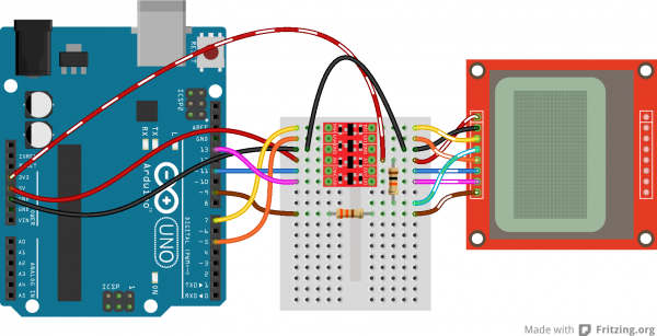
Sticking resistors in-line with the data signals is a cheap, and easy way to add some protection to the 3.3V lines. If you have an Arduino Uno (or similar 5V ‘duino) and some 10kΩ and 1kΩ resistors lying around, try this:
![Connect via resistors]()
The pins are connected the same as in the above example, however each signal has an inline resistor. There are 10kΩ resistors between the SCLK, DN, D/C, and RST pins. A 1kΩ resistor between SCE and pin 7. And the 330Ω resistor remains between pin 9 and the LED pin.
Level Converters
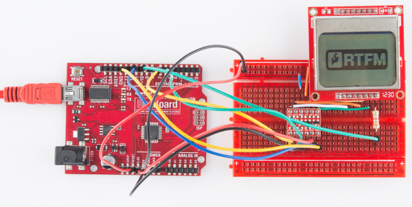
Finally, a third option for hookup is to use actual level converters to switch between 5V and 3.3V. Boards like the Bi-Directional Logic Level Converter and the TXB0104 are perfect for something like this.
![Level Shifter Example]()
Unfortunately, the LCD has five 3.3V signal inputs and the level shifters only have four channels. If you want to keep the circuit to a single shifter, you can permanently tie RST high (through a 10kΩ resistors), and run the other signals through the shifter. You lose remote reset capability, but the rest of the control remains.
Check out the hook up guides for those boards for more help in shifting the signal between Arduino and LCD.
Example Code 1: LCD Demo
With the hardware all hooked up, we’re ready to upload a sketch and start drawing on the LCD!
The Sketch
Here is a sketch-full of example LCD control code. This small novella of a sketch shows off an array of graphics driver functions, character drawing tools, and other useful functions to help you get started using the LCD. Copy/paste from below, or download the sketch by clicking here.
If you don’t have the Codebender plugin installed on your browser, you can view the same skecth below.
language:c
/* Nokia 5100 LCD Example Code
Graphics driver and PCD8544 interface code for SparkFun's
84x48 Graphic LCD.
https://www.sparkfun.com/products/10168
by: Jim Lindblom
adapted from code by Nathan Seidle and mish-mashed with
code from the ColorLCDShield.
date: October 10, 2013
license: Beerware. Feel free to use, reuse, and modify this
code as you see fit. If you find it useful, and we meet someday,
you can buy me a beer.
This all-inclusive sketch will show off a series of graphics
functions, like drawing lines, circles, squares, and text. Then
it'll go into serial monitor echo mode, where you can type
text into the serial monitor, and it'll be displayed on the
LCD.
This stuff could all be put into a library, but we wanted to
leave it all in one sketch to keep it as transparent as possible.
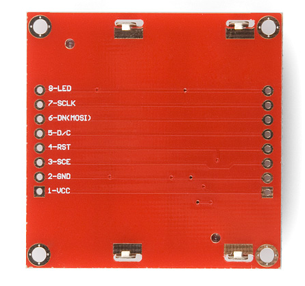
Hardware: (Note most of these pins can be swapped)
Graphic LCD Pin ---------- Arduino Pin
1-VCC ---------------- 5V
2-GND ---------------- GND
3-SCE ---------------- 7
4-RST ---------------- 6
5-D/C ---------------- 5
6-DN(MOSI) ---------------- 11
7-SCLK ---------------- 13
8-LED - 330 Ohm res -- 9
The SCLK, DN(MOSI), must remain where they are, but the other
pins can be swapped. The LED pin should remain a PWM-capable
pin. Don't forget to stick a current-limiting resistor in line
between the LCD's LED pin and Arduino pin 9!
*/
#include <SPI.h> // We'll use SPI to transfer data. Faster!
/* PCD8544-specific defines: */
#define LCD_COMMAND 0
#define LCD_DATA 1
/* 84x48 LCD Defines: */
#define LCD_WIDTH 84 // Note: x-coordinates go wide
#define LCD_HEIGHT 48 // Note: y-coordinates go high
#define WHITE 0 // For drawing pixels. A 0 draws white.
#define BLACK 1 // A 1 draws black.
/* Pin definitions:
Most of these pins can be moved to any digital or analog pin.
DN(MOSI)and SCLK should be left where they are (SPI pins). The
LED (backlight) pin should remain on a PWM-capable pin. */
const int scePin = 7; // SCE - Chip select, pin 3 on LCD.
const int rstPin = 6; // RST - Reset, pin 4 on LCD.
const int dcPin = 5; // DC - Data/Command, pin 5 on LCD.
const int sdinPin = 11; // DN(MOSI) - Serial data, pin 6 on LCD.
const int sclkPin = 13; // SCLK - Serial clock, pin 7 on LCD.
const int blPin = 9; // LED - Backlight LED, pin 8 on LCD.
/* Font table:
This table contains the hex values that represent pixels for a
font that is 5 pixels wide and 8 pixels high. Each byte in a row
represents one, 8-pixel, vertical column of a character. 5 bytes
per character. */
static const byte ASCII[][5] = {
// First 32 characters (0x00-0x19) are ignored. These are
// non-displayable, control characters.
{0x00, 0x00, 0x00, 0x00, 0x00} // 0x20
,{0x00, 0x00, 0x5f, 0x00, 0x00} // 0x21 !
,{0x00, 0x07, 0x00, 0x07, 0x00} // 0x22 "
,{0x14, 0x7f, 0x14, 0x7f, 0x14} // 0x23 #
,{0x24, 0x2a, 0x7f, 0x2a, 0x12} // 0x24 $
,{0x23, 0x13, 0x08, 0x64, 0x62} // 0x25 %
,{0x36, 0x49, 0x55, 0x22, 0x50} // 0x26 &
,{0x00, 0x05, 0x03, 0x00, 0x00} // 0x27 '
,{0x00, 0x1c, 0x22, 0x41, 0x00} // 0x28 (
,{0x00, 0x41, 0x22, 0x1c, 0x00} // 0x29 )
,{0x14, 0x08, 0x3e, 0x08, 0x14} // 0x2a *
,{0x08, 0x08, 0x3e, 0x08, 0x08} // 0x2b +
,{0x00, 0x50, 0x30, 0x00, 0x00} // 0x2c ,
,{0x08, 0x08, 0x08, 0x08, 0x08} // 0x2d -
,{0x00, 0x60, 0x60, 0x00, 0x00} // 0x2e .
,{0x20, 0x10, 0x08, 0x04, 0x02} // 0x2f /
,{0x3e, 0x51, 0x49, 0x45, 0x3e} // 0x30 0
,{0x00, 0x42, 0x7f, 0x40, 0x00} // 0x31 1
,{0x42, 0x61, 0x51, 0x49, 0x46} // 0x32 2
,{0x21, 0x41, 0x45, 0x4b, 0x31} // 0x33 3
,{0x18, 0x14, 0x12, 0x7f, 0x10} // 0x34 4
,{0x27, 0x45, 0x45, 0x45, 0x39} // 0x35 5
,{0x3c, 0x4a, 0x49, 0x49, 0x30} // 0x36 6
,{0x01, 0x71, 0x09, 0x05, 0x03} // 0x37 7
,{0x36, 0x49, 0x49, 0x49, 0x36} // 0x38 8
,{0x06, 0x49, 0x49, 0x29, 0x1e} // 0x39 9
,{0x00, 0x36, 0x36, 0x00, 0x00} // 0x3a :
,{0x00, 0x56, 0x36, 0x00, 0x00} // 0x3b ;
,{0x08, 0x14, 0x22, 0x41, 0x00} // 0x3c <
,{0x14, 0x14, 0x14, 0x14, 0x14} // 0x3d =
,{0x00, 0x41, 0x22, 0x14, 0x08} // 0x3e >
,{0x02, 0x01, 0x51, 0x09, 0x06} // 0x3f ?
,{0x32, 0x49, 0x79, 0x41, 0x3e} // 0x40 @
,{0x7e, 0x11, 0x11, 0x11, 0x7e} // 0x41 A
,{0x7f, 0x49, 0x49, 0x49, 0x36} // 0x42 B
,{0x3e, 0x41, 0x41, 0x41, 0x22} // 0x43 C
,{0x7f, 0x41, 0x41, 0x22, 0x1c} // 0x44 D
,{0x7f, 0x49, 0x49, 0x49, 0x41} // 0x45 E
,{0x7f, 0x09, 0x09, 0x09, 0x01} // 0x46 F
,{0x3e, 0x41, 0x49, 0x49, 0x7a} // 0x47 G
,{0x7f, 0x08, 0x08, 0x08, 0x7f} // 0x48 H
,{0x00, 0x41, 0x7f, 0x41, 0x00} // 0x49 I
,{0x20, 0x40, 0x41, 0x3f, 0x01} // 0x4a J
,{0x7f, 0x08, 0x14, 0x22, 0x41} // 0x4b K
,{0x7f, 0x40, 0x40, 0x40, 0x40} // 0x4c L
,{0x7f, 0x02, 0x0c, 0x02, 0x7f} // 0x4d M
,{0x7f, 0x04, 0x08, 0x10, 0x7f} // 0x4e N
,{0x3e, 0x41, 0x41, 0x41, 0x3e} // 0x4f O
,{0x7f, 0x09, 0x09, 0x09, 0x06} // 0x50 P
,{0x3e, 0x41, 0x51, 0x21, 0x5e} // 0x51 Q
,{0x7f, 0x09, 0x19, 0x29, 0x46} // 0x52 R
,{0x46, 0x49, 0x49, 0x49, 0x31} // 0x53 S
,{0x01, 0x01, 0x7f, 0x01, 0x01} // 0x54 T
,{0x3f, 0x40, 0x40, 0x40, 0x3f} // 0x55 U
,{0x1f, 0x20, 0x40, 0x20, 0x1f} // 0x56 V
,{0x3f, 0x40, 0x38, 0x40, 0x3f} // 0x57 W
,{0x63, 0x14, 0x08, 0x14, 0x63} // 0x58 X
,{0x07, 0x08, 0x70, 0x08, 0x07} // 0x59 Y
,{0x61, 0x51, 0x49, 0x45, 0x43} // 0x5a Z
,{0x00, 0x7f, 0x41, 0x41, 0x00} // 0x5b [
,{0x02, 0x04, 0x08, 0x10, 0x20} // 0x5c \
,{0x00, 0x41, 0x41, 0x7f, 0x00} // 0x5d ]
,{0x00, 0x41, 0x41, 0x7f, 0x00} // 0x5d ]
,{0x04, 0x02, 0x01, 0x02, 0x04} // 0x5e ^
,{0x40, 0x40, 0x40, 0x40, 0x40} // 0x5f _
,{0x00, 0x01, 0x02, 0x04, 0x00} // 0x60 `
,{0x20, 0x54, 0x54, 0x54, 0x78} // 0x61 a
,{0x7f, 0x48, 0x44, 0x44, 0x38} // 0x62 b
,{0x38, 0x44, 0x44, 0x44, 0x20} // 0x63 c
,{0x38, 0x44, 0x44, 0x48, 0x7f} // 0x64 d
,{0x38, 0x54, 0x54, 0x54, 0x18} // 0x65 e
,{0x08, 0x7e, 0x09, 0x01, 0x02} // 0x66 f
,{0x0c, 0x52, 0x52, 0x52, 0x3e} // 0x67 g
,{0x7f, 0x08, 0x04, 0x04, 0x78} // 0x68 h
,{0x00, 0x44, 0x7d, 0x40, 0x00} // 0x69 i
,{0x20, 0x40, 0x44, 0x3d, 0x00} // 0x6a j
,{0x7f, 0x10, 0x28, 0x44, 0x00} // 0x6b k
,{0x00, 0x41, 0x7f, 0x40, 0x00} // 0x6c l
,{0x7c, 0x04, 0x18, 0x04, 0x78} // 0x6d m
,{0x7c, 0x08, 0x04, 0x04, 0x78} // 0x6e n
,{0x38, 0x44, 0x44, 0x44, 0x38} // 0x6f o
,{0x7c, 0x14, 0x14, 0x14, 0x08} // 0x70 p
,{0x08, 0x14, 0x14, 0x18, 0x7c} // 0x71 q
,{0x7c, 0x08, 0x04, 0x04, 0x08} // 0x72 r
,{0x48, 0x54, 0x54, 0x54, 0x20} // 0x73 s
,{0x04, 0x3f, 0x44, 0x40, 0x20} // 0x74 t
,{0x3c, 0x40, 0x40, 0x20, 0x7c} // 0x75 u
,{0x1c, 0x20, 0x40, 0x20, 0x1c} // 0x76 v
,{0x3c, 0x40, 0x30, 0x40, 0x3c} // 0x77 w
,{0x44, 0x28, 0x10, 0x28, 0x44} // 0x78 x
,{0x0c, 0x50, 0x50, 0x50, 0x3c} // 0x79 y
,{0x44, 0x64, 0x54, 0x4c, 0x44} // 0x7a z
,{0x00, 0x08, 0x36, 0x41, 0x00} // 0x7b {
,{0x00, 0x00, 0x7f, 0x00, 0x00} // 0x7c |
,{0x00, 0x41, 0x36, 0x08, 0x00} // 0x7d }
,{0x10, 0x08, 0x08, 0x10, 0x08} // 0x7e ~
,{0x78, 0x46, 0x41, 0x46, 0x78} // 0x7f DEL
};
/* The displayMap variable stores a buffer representation of the
pixels on our display. There are 504 total bits in this array,
same as how many pixels there are on a 84 x 48 display.
Each byte in this array covers a 8-pixel vertical block on the
display. Each successive byte covers the next 8-pixel column over
until you reach the right-edge of the display and step down 8 rows.
To update the display, we first have to write to this array, then
call the updateDisplay() function, which sends this whole array
to the PCD8544.
Because the PCD8544 won't let us write individual pixels at a
time, this is how we can make targeted changes to the display. */
byte displayMap[LCD_WIDTH * LCD_HEIGHT / 8] = {
0x00, 0x00, 0x00, 0x00, 0x00, 0x00, 0x00, 0x00, 0x00, 0x00, 0x00, 0x00, // (0,0)->(11,7) ~ These 12 bytes cover an 8x12 block in the left corner of the display
0x00, 0x00, 0x00, 0x00, 0x00, 0x00, 0x00, 0x00, 0x00, 0x00, 0x00, 0x00, // (12,0)->(23,7)
0x00, 0x00, 0x00, 0x00, 0x00, 0x00, 0x00, 0x00, 0x00, 0x00, 0x00, 0xE0, // (24,0)->(35,7)
0xF0, 0xF8, 0xFC, 0xFC, 0xFE, 0xFE, 0xFE, 0xFE, 0x1E, 0x0E, 0x02, 0x00, // (36,0)->(47,7)
0x00, 0x00, 0x00, 0x00, 0x00, 0x00, 0x00, 0x00, 0x00, 0x00, 0x00, 0x00, // (48,0)->(59,7)
0x00, 0x00, 0x00, 0x00, 0x00, 0x00, 0x00, 0x00, 0x00, 0x00, 0x00, 0x00, // (60,0)->(71,7)
0x00, 0x00, 0x00, 0x00, 0x00, 0x00, 0x00, 0x00, 0x00, 0x00, 0x00, 0x00, // (72,0)->(83,7)
0x00, 0x00, 0x00, 0x00, 0x00, 0x00, 0x00, 0x00, 0x00, 0x00, 0x00, 0x00, // (0,8)->(11,15)
0x00, 0x00, 0x00, 0x00, 0x00, 0x00, 0x00, 0x00, 0x00, 0x00, 0x00, 0x00, // (12,8)->(23,15)
0x00, 0x00, 0x00, 0x00, 0x00, 0x00, 0x00, 0x00, 0x00, 0x00, 0x00, 0x03, // (24,8)->(35,15)
0x0F, 0x1F, 0x3F, 0x7F, 0xFF, 0xFF, 0xFF, 0xFF, 0xFF, 0xFE, 0xFC, 0xF8, // (36,8)->(47,15)
0xF8, 0xF0, 0xF8, 0xFE, 0xFE, 0xFC, 0xF8, 0xE0, 0x00, 0x00, 0x00, 0x00, // (48,8)->(59,15)
0x00, 0x00, 0x00, 0x00, 0x00, 0x00, 0x00, 0x00, 0x00, 0x00, 0x00, 0x00, // (60,8)->(71,15)
0x00, 0x00, 0x00, 0x00, 0x00, 0x00, 0x00, 0x00, 0x00, 0x00, 0x00, 0x00, // (72,8)->(83,15)
0x00, 0x00, 0x00, 0x00, 0x00, 0x00, 0x00, 0x00, 0x00, 0x00, 0x00, 0x00, // (0,16)->(11,23)
0x00, 0x00, 0x00, 0x00, 0x00, 0x00, 0x00, 0x00, 0x00, 0x00, 0x00, 0x00, // (12,16)->(23,23)
0x00, 0x00, 0xF8, 0xFC, 0xFE, 0xFE, 0xFF, 0xFF, 0xF3, 0xE0, 0xE0, 0xC0, // (24,16)->(35,23)
0xC0, 0xC0, 0xE0, 0xE0, 0xF1, 0xFF, 0xFF, 0xFF, 0xFF, 0xFF, 0xFF, 0xFF, // (36,16)->(47,23)
0xFF, 0xFF, 0xFF, 0xFF, 0xFF, 0xFF, 0xFF, 0xFF, 0x3E, 0x00, 0x00, 0x00, // (48,16)->(59,23)
0x00, 0x00, 0x00, 0x00, 0x00, 0x00, 0x00, 0x00, 0x00, 0x00, 0x00, 0x00, // (60,16)->(71,23)
0x00, 0x00, 0x00, 0x00, 0x00, 0x00, 0x00, 0x00, 0x00, 0x00, 0x00, 0x00, // (72,16)->(83,23)
0x00, 0x00, 0x00, 0x00, 0x00, 0x00, 0x00, 0x00, 0x00, 0x00, 0x00, 0x00, // (0,24)->(11,31)
0x00, 0x00, 0x00, 0x00, 0x00, 0x00, 0x00, 0x00, 0x00, 0x00, 0x00, 0x00, // (12,24)->(23,31)
0x00, 0x00, 0xFF, 0xFF, 0xFF, 0xFF, 0xFF, 0xFF, 0xFF, 0xFF, 0xFF, 0xFF, // (24,24)->(35,31)
0xFF, 0xFF, 0xFF, 0xFF, 0xFF, 0xFF, 0xFF, 0xFF, 0xFF, 0xFF, 0xFF, 0xFF, // (36,24)->(47,31)
0xFF, 0xFF, 0xFF, 0x7F, 0x3F, 0x1F, 0x07, 0x01, 0x00, 0x00, 0x00, 0x00, // (48,24)->(59,31)
0x00, 0x00, 0x00, 0x00, 0x00, 0x00, 0x00, 0x00, 0x00, 0x00, 0x00, 0x00, // (60,24)->(71,31)
0x00, 0x00, 0x00, 0x00, 0x00, 0x00, 0x00, 0x00, 0x00, 0x00, 0x00, 0x00, // (72,24)->(83,31)
0x00, 0x00, 0x00, 0x00, 0x00, 0x00, 0x00, 0x00, 0x00, 0x00, 0x00, 0x00, // (0,32)->(11,39)
0x00, 0x00, 0x00, 0x00, 0x00, 0x00, 0x00, 0x00, 0x00, 0x00, 0x00, 0x00, // (12,32)->(23,39)
0x00, 0x00, 0xFF, 0xFF, 0xFF, 0xFF, 0xFF, 0xFF, 0xFF, 0x7F, 0x3F, 0x1F, // (24,32)->(35,39)
0x0F, 0x0F, 0x0F, 0x07, 0x07, 0x07, 0x07, 0x07, 0x07, 0x07, 0x03, 0x03, // (36,32)->(47,39)
0x01, 0x01, 0x00, 0x00, 0x00, 0x00, 0x00, 0x00, 0x00, 0x00, 0x00, 0x00, // (48,32)->(59,39)
0x00, 0x00, 0x00, 0x00, 0x00, 0x00, 0x00, 0x00, 0x00, 0x00, 0x00, 0x00, // (60,32)->(71,39)
0x00, 0x00, 0x00, 0x00, 0x00, 0x00, 0x00, 0x00, 0x00, 0x00, 0x00, 0x00, // (72,32)->(83,39)
0x00, 0x00, 0x00, 0x00, 0x00, 0x00, 0x00, 0x00, 0x00, 0x00, 0x00, 0x00, // (0,40)->(11,47)
0x00, 0x00, 0x00, 0x00, 0x00, 0x00, 0x00, 0x00, 0x00, 0x00, 0x00, 0x00, // (12,40)->(23,47)
0x00, 0x00, 0x3F, 0x1F, 0x0F, 0x07, 0x03, 0x01, 0x00, 0x00, 0x00, 0x00, // (24,40)->(35,47)
0x00, 0x00, 0x00, 0x00, 0x00, 0x00, 0x00, 0x00, 0x00, 0x00, 0x00, 0x00, // (36,40)->(47,47)
0x00, 0x00, 0x00, 0x00, 0x00, 0x00, 0x00, 0x00, 0x00, 0x00, 0x00, 0x00, // (48,40)->(59,47)
0x00, 0x00, 0x00, 0x00, 0x00, 0x00, 0x00, 0x00, 0x00, 0x00, 0x00, 0x00, // (60,40)->(71,47)
0x00, 0x00, 0x00, 0x00, 0x00, 0x00, 0x00, 0x00, 0x00, 0x00, 0x00, 0x00, // (72,40)->(83,47) !!! The bottom right pixel!
};
/* This array is the same size as the displayMap. We'll use it
as an example of how to draw a bitmap. xkcd comic transposing
makes for an excellent display application.
For reference, see: http://xkcd.com/149/ */
char xkcdSandwich[504] = {
0xFF, 0x8D, 0x9F, 0x13, 0x13, 0xF3, 0x01, 0x01, 0xF9, 0xF9, 0x01, 0x81, 0xF9, 0xF9, 0x01, 0xF1,
0xF9, 0x09, 0x09, 0xFF, 0xFF, 0xF1, 0xF9, 0x09, 0x09, 0xF9, 0xF1, 0x01, 0x01, 0x01, 0x01, 0x01,
0xF9, 0xF9, 0x09, 0xF9, 0x09, 0xF9, 0xF1, 0x01, 0xC1, 0xE9, 0x29, 0x29, 0xF9, 0xF1, 0x01, 0xFF,
0xFF, 0x71, 0xD9, 0x01, 0x01, 0xF1, 0xF9, 0x29, 0x29, 0xB9, 0xB1, 0x01, 0x01, 0x01, 0xF1, 0xF1,
0x11, 0xF1, 0xF1, 0xF1, 0xE1, 0x01, 0xE1, 0xF1, 0x51, 0x51, 0x71, 0x61, 0x01, 0x01, 0xC1, 0xF1,
0x31, 0x31, 0xF1, 0xFF, 0xFF, 0x00, 0x01, 0x01, 0x01, 0x01, 0x60, 0xE0, 0xA0, 0x01, 0x01, 0x81,
0xE1, 0x61, 0x60, 0xC0, 0x01, 0xE1, 0xE1, 0x21, 0x21, 0xE0, 0xC1, 0x01, 0xC1, 0xE1, 0x20, 0x20,
0xFC, 0xFC, 0xE0, 0xE0, 0xC1, 0xE1, 0xE0, 0xC1, 0xE0, 0xE1, 0x01, 0xFC, 0xFC, 0x21, 0x21, 0xE1,
0xC1, 0xE5, 0xE4, 0x01, 0xC1, 0xE0, 0x20, 0x21, 0x20, 0x00, 0x01, 0xFD, 0xFD, 0x21, 0x20, 0xE0,
0x00, 0x00, 0x01, 0x01, 0xC0, 0x61, 0x31, 0x31, 0x21, 0x20, 0xC0, 0x81, 0x01, 0x01, 0x01, 0x00,
0x00, 0x00, 0x00, 0x01, 0x01, 0x01, 0x01, 0xFF, 0xFF, 0x00, 0x00, 0x00, 0x00, 0x01, 0x03, 0x02,
0x03, 0x01, 0x00, 0x01, 0x03, 0xF2, 0x1A, 0x0B, 0x08, 0x0B, 0x1B, 0x10, 0x60, 0xE3, 0x03, 0x00,
0x01, 0x03, 0x02, 0x02, 0x03, 0x03, 0x00, 0x03, 0x03, 0x00, 0x00, 0x03, 0x03, 0x00, 0x00, 0x03,
0x03, 0x00, 0x00, 0x03, 0x03, 0x03, 0x03, 0x00, 0x01, 0x03, 0x02, 0x02, 0x03, 0x01, 0x00, 0x03,
0x03, 0x00, 0x00, 0x03, 0x00, 0x00, 0x00, 0x3E, 0x63, 0x80, 0x80, 0x80, 0x80, 0x60, 0x3F, 0x07,
0x00, 0x00, 0x00, 0x00, 0x00, 0x00, 0x00, 0x00, 0x00, 0x00, 0x00, 0xFF, 0xFF, 0x00, 0x00, 0x00,
0x00, 0x00, 0x00, 0x00, 0xFE, 0x01, 0x01, 0x01, 0x02, 0x03, 0x3E, 0xE8, 0xF8, 0xF0, 0xD0, 0x90,
0x18, 0x0F, 0x00, 0x00, 0x00, 0x00, 0x00, 0x00, 0x00, 0x00, 0x00, 0x00, 0x00, 0x00, 0x00, 0x00,
0x00, 0x00, 0x00, 0x00, 0x00, 0x00, 0x00, 0x00, 0x00, 0x00, 0x00, 0x00, 0x00, 0x00, 0x00, 0x00,
0x00, 0x00, 0x00, 0x00, 0x00, 0x00, 0x00, 0x00, 0x00, 0x00, 0x00, 0x00, 0x00, 0xC0, 0x38, 0xFF,
0x0C, 0x38, 0xE0, 0x80, 0x00, 0x00, 0x00, 0x00, 0x00, 0x00, 0x00, 0x00, 0x00, 0x00, 0x00, 0xFF,
0xFF, 0x00, 0x00, 0x00, 0x00, 0x00, 0x00, 0x00, 0x1F, 0xF0, 0x00, 0x00, 0x00, 0x00, 0x00, 0x33,
0x5F, 0x8F, 0x84, 0x05, 0x07, 0x06, 0x0C, 0x0E, 0x0E, 0x0C, 0x14, 0x34, 0x68, 0x88, 0xD8, 0x70,
0x00, 0x00, 0x00, 0x00, 0x00, 0xE0, 0x10, 0x10, 0x10, 0xF0, 0xE0, 0x00, 0xF0, 0xF0, 0x00, 0x80,
0x80, 0x00, 0x00, 0x80, 0x80, 0x80, 0x80, 0x00, 0x80, 0x80, 0x00, 0x80, 0x00, 0x00, 0x20, 0x38,
0x0E, 0x01, 0xC0, 0x3F, 0xE0, 0x00, 0x00, 0x03, 0x0E, 0x08, 0x00, 0x00, 0x00, 0x00, 0x00, 0x00,
0x00, 0x00, 0x00, 0xFF, 0xFF, 0x80, 0x80, 0x80, 0x80, 0x80, 0x80, 0x80, 0xB6, 0xED, 0xC0, 0xC0,
0xC0, 0xE0, 0xA0, 0xA0, 0xA0, 0xA0, 0xA1, 0xA1, 0xA1, 0xA1, 0xA1, 0xA1, 0xA1, 0xE1, 0xE1, 0xC1,
0xEF, 0xBB, 0x83, 0x86, 0x88, 0xB0, 0x80, 0x80, 0x80, 0x8F, 0x90, 0x90, 0x90, 0x9F, 0x8F, 0x80,
0x9F, 0x9F, 0x87, 0x8D, 0x98, 0x80, 0x8C, 0x9E, 0x92, 0x92, 0x9F, 0xC0, 0xC7, 0xFF, 0xB8, 0x8F,
0x80, 0x90, 0x90, 0xC0, 0xF0, 0x8E, 0x81, 0x80, 0x81, 0x8F, 0xB8, 0xE0, 0x80, 0x80, 0x80, 0x80,
0x80, 0x80, 0x80, 0x80, 0x80, 0x80, 0x80, 0xFF,
};
void setup()
{
Serial.begin(9600);
lcdBegin(); // This will setup our pins, and initialize the LCD
setContrast(55); // Pretty good value, play around with it
updateDisplay(); // with displayMap untouched, SFE logo
delay(2000);
lcdFunTime(); // Runs a 30-second demo of graphics functions
// Wait for serial to come in, then clear display and go to echo
while (!Serial.available())
;
clearDisplay(WHITE);
updateDisplay();
}
// Loop turns the display into a local serial monitor echo.
// Type to the Arduino from the serial monitor, and it'll echo
// what you type on the display. Type ~ to clear the display.
void loop()
{
static int cursorX = 0;
static int cursorY = 0;
if (Serial.available())
{
char c = Serial.read();
switch (c)
{
case '\n': // New line
cursorY += 8;
break;
case '\r': // Return feed
cursorX = 0;
break;
case '~': // Use ~ to clear the screen.
clearDisplay(WHITE);
updateDisplay();
cursorX = 0; // reset the cursor
cursorY = 0;
break;
default:
setChar(c, cursorX, cursorY, BLACK);
updateDisplay();
cursorX += 6; // Increment cursor
break;
}
// Manage cursor
if (cursorX >= (LCD_WIDTH - 4))
{ // If the next char will be off screen...
cursorX = 0; // ... reset x to 0...
cursorY += 8; // ...and increment to next line.
if (cursorY >= (LCD_HEIGHT - 7))
{ // If the next line takes us off screen...
cursorY = 0; // ...go back to the top.
}
}
}
}
/* This function serves as a fun demo of the graphics driver
functions below. */
void lcdFunTime()
{
clearDisplay(WHITE); // Begin by clearing the display
randomSeed(analogRead(A0));
/* setPixel Example */
const int pixelCount = 100;
for (int i=0; i<pixelCount; i++)
{
// setPixel takes 2 to 3 parameters. The first two params
// are x and y variables. The third optional variable is
// a "color" boolean. 1 for black, 0 for white.
// setPixel() with two variables will set the pixel with
// the color set to black.
// clearPixel() will call setPixel with with color set to
// white.
setPixel(random(0, LCD_WIDTH), random(0, LCD_HEIGHT));
// After drawing something, we must call updateDisplay()
// to actually make the display draw something new.
updateDisplay();
delay(10);
}
setStr("full of stars", 0, LCD_HEIGHT-8, BLACK);
updateDisplay();
delay(1000);
// Seizure time!!! Err...demoing invertDisplay()
for (int i=0; i<5; i++)
{
invertDisplay(); // This will swap all bits in our display
delay(200);
invertDisplay(); // This will get us back to where we started
delay(200);
}
delay(2000);
/* setLine Example */
clearDisplay(WHITE); // Start fresh
int x0 = LCD_WIDTH/2;
int y0 = LCD_HEIGHT/2;
for (float i=0; i<2*PI; i+=PI/8)
{
// Time to whip out some maths:
const int lineLength = 24;
int x1 = x0 + lineLength * sin(i);
int y1 = y0 + lineLength * cos(i);
// setLine(x0, y0, x1, y1, bw) takes five variables. The
// first four are coordinates for the start and end of the
// line. The last variable is the color (1=black, 0=white).
setLine(x0, y0, x1, y1, BLACK);
updateDisplay();
delay(100);
}
// Demo some backlight tuning
for (int j=0; j<2; j++)
{
for (int i=255; i>=0; i-=5)
{
analogWrite(blPin, i); // blPin is ocnnected to BL LED
delay(20);
}
for (int i=0; i<256; i+=5)
{
analogWrite(blPin, i);
delay(20);
}
}
/* setRect Example */
clearDisplay(WHITE); // Start fresh
// setRect takes six parameters (x0, y0, x1, y0, fill, bw)
// x0, y0, x1, and y0 are the two diagonal corner coordinates
// fill is a boolean, which determines if the rectangle is
// filled in. bw determines the color 0=white, 1=black.
for (int x=0; x<LCD_WIDTH; x+=8)
{ // Swipe right black
setRect(0, 0, x, LCD_HEIGHT, 1, BLACK);
updateDisplay();
delay(10);
}
for (int x=0; x<LCD_WIDTH; x+=8)
{ // Swipe right white
setRect(0, 0, x, LCD_HEIGHT, 1, WHITE);
updateDisplay();
delay(10);
}
for (int x=0; x<12; x++)
{ // Shutter swipe
setRect(0, 0, x, LCD_HEIGHT, 1, 1);
setRect(11, 0, x+12, LCD_HEIGHT, 1, BLACK);
setRect(23, 0, x+24, LCD_HEIGHT, 1, BLACK);
setRect(35, 0, x+36, LCD_HEIGHT, 1, BLACK);
setRect(47, 0, x+48, LCD_HEIGHT, 1, BLACK);
setRect(59, 0, x+60, LCD_HEIGHT, 1, BLACK);
setRect(71, 0, x+72, LCD_HEIGHT, 1, BLACK);
updateDisplay();
delay(10);
}
// 3 Dee!
setRect(25, 10, 45, 30, 0, WHITE);
setRect(35, 20, 55, 40, 0, WHITE);
setLine(25, 10, 35, 20, WHITE);
setLine(45, 30, 55, 40, WHITE);
setLine(25, 30, 35, 40, WHITE);
setLine(45, 10, 55, 20, WHITE);
updateDisplay();
delay(2000);
/* setCircle Example */
clearDisplay(WHITE);
// setCircle takes 5 parameters -- x0, y0, radius, bw, and
// lineThickness. x0 and y0 are the center coords of the circ.
// radius is the...radius. bw is the color (0=white, 1=black)
// lineThickness is the line width of the circle, 1 = smallest
// thickness moves in towards center.
for (int i=0; i<20; i++)
{
int x = random(0, LCD_WIDTH);
int y = random(0, LCD_HEIGHT);
setCircle(x, y, i, BLACK, 1);
updateDisplay();
delay(100);
}
delay(2000);
/* setChar & setStr Example */
// setStr takes 4 parameters: an array of characters to print,
// x and y coordinates for the top-left corner. And a color
setStr("Modern Art", 0, 10, WHITE);
updateDisplay();
delay(2000);
/* setBitmap Example */
// setBitmap takes one parameter, an array of the same size
// as our screen.
setBitmap(xkcdSandwich);
updateDisplay();
}
// Because I keep forgetting to put bw variable in when setting...
void setPixel(int x, int y)
{
setPixel(x, y, BLACK); // Call setPixel with bw set to Black
}
void clearPixel(int x, int y)
{
setPixel(x, y, WHITE); // call setPixel with bw set to white
}
// This function sets a pixel on displayMap to your preferred
// color. 1=Black, 0= white.
void setPixel(int x, int y, boolean bw)
{
// First, double check that the coordinate is in range.
if ((x >= 0) && (x < LCD_WIDTH) && (y >= 0) && (y < LCD_HEIGHT))
{
byte shift = y % 8;
if (bw) // If black, set the bit.
displayMap[x + (y/8)*LCD_WIDTH] |= 1<<shift;
else // If white clear the bit.
displayMap[x + (y/8)*LCD_WIDTH] &= ~(1<<shift);
}
}
// setLine draws a line from x0,y0 to x1,y1 with the set color.
// This function was grabbed from the SparkFun ColorLCDShield
// library.
void setLine(int x0, int y0, int x1, int y1, boolean bw)
{
int dy = y1 - y0; // Difference between y0 and y1
int dx = x1 - x0; // Difference between x0 and x1
int stepx, stepy;
if (dy < 0)
{
dy = -dy;
stepy = -1;
}
else
stepy = 1;
if (dx < 0)
{
dx = -dx;
stepx = -1;
}
else
stepx = 1;
dy <<= 1; // dy is now 2*dy
dx <<= 1; // dx is now 2*dx
setPixel(x0, y0, bw); // Draw the first pixel.
if (dx > dy)
{
int fraction = dy - (dx >> 1);
while (x0 != x1)
{
if (fraction >= 0)
{
y0 += stepy;
fraction -= dx;
}
x0 += stepx;
fraction += dy;
setPixel(x0, y0, bw);
}
}
else
{
int fraction = dx - (dy >> 1);
while (y0 != y1)
{
if (fraction >= 0)
{
x0 += stepx;
fraction -= dy;
}
y0 += stepy;
fraction += dx;
setPixel(x0, y0, bw);
}
}
}
// setRect will draw a rectangle from x0,y0 top-left corner to
// a x1,y1 bottom-right corner. Can be filled with the fill
// parameter, and colored with bw.
// This function was grabbed from the SparkFun ColorLCDShield
// library.
void setRect(int x0, int y0, int x1, int y1, boolean fill, boolean bw)
{
// check if the rectangle is to be filled
if (fill == 1)
{
int xDiff;
if(x0 > x1)
xDiff = x0 - x1; //Find the difference between the x vars
else
xDiff = x1 - x0;
while(xDiff > 0)
{
setLine(x0, y0, x0, y1, bw);
if(x0 > x1)
x0--;
else
x0++;
xDiff--;
}
}
else
{
// best way to draw an unfilled rectangle is to draw four lines
setLine(x0, y0, x1, y0, bw);
setLine(x0, y1, x1, y1, bw);
setLine(x0, y0, x0, y1, bw);
setLine(x1, y0, x1, y1, bw);
}
}
// setCircle draws a circle centered around x0,y0 with a defined
// radius. The circle can be black or white. And have a line
// thickness ranging from 1 to the radius of the circle.
// This function was grabbed from the SparkFun ColorLCDShield
// library.
void setCircle (int x0, int y0, int radius, boolean bw, int lineThickness)
{
for(int r = 0; r < lineThickness; r++)
{
int f = 1 - radius;
int ddF_x = 0;
int ddF_y = -2 * radius;
int x = 0;
int y = radius;
setPixel(x0, y0 + radius, bw);
setPixel(x0, y0 - radius, bw);
setPixel(x0 + radius, y0, bw);
setPixel(x0 - radius, y0, bw);
while(x < y)
{
if(f >= 0)
{
y--;
ddF_y += 2;
f += ddF_y;
}
x++;
ddF_x += 2;
f += ddF_x + 1;
setPixel(x0 + x, y0 + y, bw);
setPixel(x0 - x, y0 + y, bw);
setPixel(x0 + x, y0 - y, bw);
setPixel(x0 - x, y0 - y, bw);
setPixel(x0 + y, y0 + x, bw);
setPixel(x0 - y, y0 + x, bw);
setPixel(x0 + y, y0 - x, bw);
setPixel(x0 - y, y0 - x, bw);
}
radius--;
}
}
// This function will draw a char (defined in the ASCII table
// near the beginning of this sketch) at a defined x and y).
// The color can be either black (1) or white (0).
void setChar(char character, int x, int y, boolean bw)
{
byte column; // temp byte to store character's column bitmap
for (int i=0; i<5; i++) // 5 columns (x) per character
{
column = ASCII[character - 0x20][i];
for (int j=0; j<8; j++) // 8 rows (y) per character
{
if (column & (0x01 << j)) // test bits to set pixels
setPixel(x+i, y+j, bw);
else
setPixel(x+i, y+j, !bw);
}
}
}
// setStr draws a string of characters, calling setChar with
// progressive coordinates until it's done.
// This function was grabbed from the SparkFun ColorLCDShield
// library.
void setStr(char * dString, int x, int y, boolean bw)
{
while (*dString != 0x00) // loop until null terminator
{
setChar(*dString++, x, y, bw);
x+=5;
for (int i=y; i<y+8; i++)
{
setPixel(x, i, !bw);
}
x++;
if (x > (LCD_WIDTH - 5)) // Enables wrap around
{
x = 0;
y += 8;
}
}
}
// This function will draw an array over the screen. (For now) the
// array must be the same size as the screen, covering the entirety
// of the display.
void setBitmap(char * bitArray)
{
for (int i=0; i<(LCD_WIDTH * LCD_HEIGHT / 8); i++)
displayMap[i] = bitArray[i];
}
// This function clears the entire display either white (0) or
// black (1).
// The screen won't actually clear until you call updateDisplay()!
void clearDisplay(boolean bw)
{
for (int i=0; i<(LCD_WIDTH * LCD_HEIGHT / 8); i++)
{
if (bw)
displayMap[i] = 0xFF;
else
displayMap[i] = 0;
}
}
// Helpful function to directly command the LCD to go to a
// specific x,y coordinate.
void gotoXY(int x, int y)
{
LCDWrite(0, 0x80 | x); // Column.
LCDWrite(0, 0x40 | y); // Row. ?
}
// This will actually draw on the display, whatever is currently
// in the displayMap array.
void updateDisplay()
{
gotoXY(0, 0);
for (int i=0; i < (LCD_WIDTH * LCD_HEIGHT / 8); i++)
{
LCDWrite(LCD_DATA, displayMap[i]);
}
}
// Set contrast can set the LCD Vop to a value between 0 and 127.
// 40-60 is usually a pretty good range.
void setContrast(byte contrast)
{
LCDWrite(LCD_COMMAND, 0x21); //Tell LCD that extended commands follow
LCDWrite(LCD_COMMAND, 0x80 | contrast); //Set LCD Vop (Contrast): Try 0xB1(good @ 3.3V) or 0xBF if your display is too dark
LCDWrite(LCD_COMMAND, 0x20); //Set display mode
}
/* There are two ways to do this. Either through direct commands
to the display, or by swapping each bit in the displayMap array.
We'll leave both methods here, comment one or the other out if
you please. */
void invertDisplay()
{
/* Direct LCD Command option
LCDWrite(LCD_COMMAND, 0x20); //Tell LCD that extended commands follow
LCDWrite(LCD_COMMAND, 0x08 | 0x05); //Set LCD Vop (Contrast): Try 0xB1(good @ 3.3V) or 0xBF if your display is too dark
LCDWrite(LCD_COMMAND, 0x20); //Set display mode */
/* Indirect, swap bits in displayMap option: */
for (int i=0; i < (LCD_WIDTH * LCD_HEIGHT / 8); i++)
{
displayMap[i] = ~displayMap[i] & 0xFF;
}
updateDisplay();
}
// There are two memory banks in the LCD, data/RAM and commands.
// This function sets the DC pin high or low depending, and then
// sends the data byte
void LCDWrite(byte data_or_command, byte data)
{
//Tell the LCD that we are writing either to data or a command
digitalWrite(dcPin, data_or_command);
//Send the data
digitalWrite(scePin, LOW);
SPI.transfer(data); //shiftOut(sdinPin, sclkPin, MSBFIRST, data);
digitalWrite(scePin, HIGH);
}
//This sends the magical commands to the PCD8544
void lcdBegin(void)
{
//Configure control pins
pinMode(scePin, OUTPUT);
pinMode(rstPin, OUTPUT);
pinMode(dcPin, OUTPUT);
pinMode(sdinPin, OUTPUT);
pinMode(sclkPin, OUTPUT);
pinMode(blPin, OUTPUT);
analogWrite(blPin, 255);
SPI.begin();
SPI.setDataMode(SPI_MODE0);
SPI.setBitOrder(MSBFIRST);
//Reset the LCD to a known state
digitalWrite(rstPin, LOW);
digitalWrite(rstPin, HIGH);
LCDWrite(LCD_COMMAND, 0x21); //Tell LCD extended commands follow
LCDWrite(LCD_COMMAND, 0xB0); //Set LCD Vop (Contrast)
LCDWrite(LCD_COMMAND, 0x04); //Set Temp coefficent
LCDWrite(LCD_COMMAND, 0x14); //LCD bias mode 1:48 (try 0x13)
//We must send 0x20 before modifying the display control mode
LCDWrite(LCD_COMMAND, 0x20);
LCDWrite(LCD_COMMAND, 0x0C); //Set display control, normal mode.
}
For help understanding the sketch, check the comments in the code. Most of the action takes place in the lcdFunTime() function.
The Sketch in Action
Once uploaded to your Arduino, the sketch will begin by running the demo – a set of basic animations and graphics functions. To begin, we’ll draw some random pixels on the screen (“It’s full of stars…”). Then we’ll move on to examples of drawing lines, rectangles, and circles. Throughout there are examples of drawing characters and strings. Finally the demo closes out with an homage to a monochrome comic which seems a perfect fit for this little monochrome LCD.
![Sandwich example]()
This is a demo of drawing bitmaps on the screen, which is one of the more rewarding tasks we can accomplish with the ‘duino/LCD combo.
After the demo runs its course, the sketch will enter into a serial echo mode. Open the serial monitor (set the baud rate to 9600 bps), and type stuff over to the Arduino. It should start printing everything you send it onto the LCD.
If you’re intrigued by the possibilites of drawing bitmaps on the screen, check out the next page! We’ll show you how to import your own 84x48 bitmap and draw it on the screen.
Example Code 2: Drawing Bitmaps
If the last demo has you chomping at the bit to design your own 84x48 bitmaps and display them, continue reading through this example. We’ll show you how to scale and import a bitmap, then compile it into your Arduino code and send it to the LCD, so you can have your own, sillly graphic.
![alt text]()
Find/Make/Modify a Bitmap
To begin, find a bitmap image that you’d like to print to the LCD. 84x48 monochrome pixels doesn’t give you a lot of room, but you can still get some fun stuff on there. Here are a few examples:
![RTFM example]()
![Arduino example]()
![Bender Example]()
![Flame example]()
![XKCD example]()
After you’ve picked an image, you’ll need to massage it to make it both monochrome (2-bit color) and 84 x 48 pixels. Most standard image editors can help with this. For Windows users, Paint is all you need to scale the image. Then save it as a monochrome bitmap.
Convert Bitmap to Array
The next step is converting that regular image file to a 504-byte array of char’s. There are a number of programs that can help with this around the web. We recommend LCD Assistant.
To load up an image in LCD Assistant, go to File>Load Image. A preview of the image should open up, make sure it’s the right size – 84 pixels wide, 48 pixels tall. Also make sure the Byte orientation is set to Vertical and the Size endianness is set to Little. The rest of the default settings (8 pixels/byte, etc.) should already be set correctly:
![LCD Assistant Settings]()
Then go to File>Save output to generate a temporary text file. Open that text file to have a look at your shiny new array. You’ll need to modify the type of the array to be just a char (no unsigned or const). Also make sure the array has the proper naming conventions (no dashes, don’t start with a number, etc.).
Import into the Sketch and Draw!
With that array created, copy the entire table over to your Arduino sketch. Use the same sketch from Example 1. Paste the array wherever you’d like. Now, to test out your drawing, replace the setup() and loop() in the last sketch with the below (making sure the rest of the functions and variables remain in the sketch):
language:c

// ...LCD definitions, variables, and bitmap array defined above.

void setup()
{
  lcdBegin(); // This will setup our pins, and initialize the LCD
  setContrast(60); // Good values range from 40-60
  setBitmap(flameBitmap); // flameBitmap should be replaced with the name of your BMP array
  updateDisplay();  // Update the display to make the array show up.
}

void loop()
{
}

// LCD control and graphics functions defined below...
Fun stuff! Now you can overlay text, or draw on on your bitmap. You can even try importing multiple graphics to create animations!
Resources & Going Further
Thanks for checking out our Monochrome 84 x 48 Graphic LCD Hookup Guide! Should you require any further resources to get your LCD up and running, here are some handy places to look:
- LCD and Driver Resources
- Arduino Libraries and Code
- Bitmap Tools
Going Further
Now that you’ve got control of your graphic LCD, you can embed it into all sorts of cool projects. If you need some inspiration, here are some related tutorials to help you out:
- OLED Display Hookup Guide– While not exactly an LCD, this OLED provides a nice, crisp text display to your project.
- MP3 Player Shield Music Box– This MP3 Player Music Box could be well served by a sweet graphic display. Hmm…
- ITG-3200 Hookup Guide– The ITG-3200 is a fully-featured 3-axis gyroscope sensor. This display could be used to create a visual angular velocity meter.
learn.sparkfun.com |CC BY-SA 3.0
| SparkFun Electronics | Boulder, Colorado