Weather Shield Hookup Guide a learn.sparkfun.com tutorial
Weather Shield Overview
The Weather Shield is an easy to use Arduino shield that grants you access to barometric pressure, relative humidity, luminosity, and temperature. There are also connections to optional sensors such as wind speed/direction, rain gauge, and GPS for location and super accurate timing.

The bare Weather Shield
Things you should know about this shield:
- Uses the HTU21D humidity sensor, MPL3115A2 barometric pressure sensor, and ALS-PT19 light sensor.
- Has connector for the GP-635T compact GPS module
- Has optional connectors for the SparkFun weather meters
- Weather shield can operate from 3V to 6V and has built in voltage regulators and signal translators
- Typical humidity accuracy of ±2%
- Typical pressure accuracy of ±50Pa
- Typical temperature accuracy of ±0.3C
Suggested Reading
- I2C Protocol
- Installing an Arduino library
- How to install Arduino shield headers
- What are pull-up resistors?
- HTU21D Humidity Sensor Hookup Guide
- GP-635T GPS Module Hookup Guide
Hooking It Up
To get up and running with the Weather Shield you’ll need the following parts:
- Arduino, RedBoard, or other compatible board
- Arduino Stackable Headers
- Optional: GP-645T GPS Module and 1.75" mating cable
- Optional: Two RJ11 6-pin Connectors
- Optional: Weather Meters
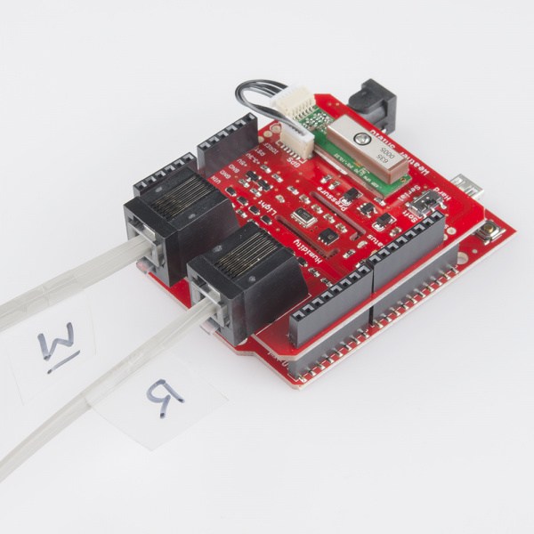
Shield on a RedBoard with optional weather meter (‘W'ind and 'R'ain cables) and GPS attached
Assembly
Solder the stackable headers onto the shield, and insert the shield into your Arduino. You are welcome to solder in the RJ11 connectors to the top of the board as well. If you have the GP-635T GPS module, don’t worry about attaching it at this time, we’ll get to GPS later.
Example Firmware
The Weather Shield example relies on the HTU21D and MPL3115A2 libraries. Download the libraries here then install them into your Documents/Arduino folder.
Grab the example sketch, and load it onto your Arduino. Open the serial monitor at 9600bps. You should see an output string every second containing the current weather information:
$,winddir=0,windspeedmph=0,windspdmph_avg2m=0.0,winddir_avg2m=0,windgustmph_10m=0.0,windgustdir_10m=0,humidity=31.7,tempf=76.3,rainin=0.00,dailyrainin=0.00,pressure=81525.25,batt_lvl=4.32,light_lvl=2.03,#

$,winddir=0,windspeedmph=0,windspdmph_avg2m=0.0,winddir_avg2m=0,windgustmph_10m=0.0,windgustdir_10m=0,humidity=31.7,tempf=76.3,rainin=0.00,dailyrainin=0.00,pressure=81520.75,batt_lvl=4.32,light_lvl=2.02,#

$,winddir=0,windspeedmph=0,windspdmph_avg2m=0.0,winddir_avg2m=0,windgustmph_10m=0.0,windgustdir_10m=0,humidity=31.7,tempf=76.3,rainin=0.00,dailyrainin=0.00,pressure=81517.50,batt_lvl=4.34,light_lvl=2.11,#

$,winddir=0,windspeedmph=0,windspdmph_avg2m=0.0,winddir_avg2m=0,windgustmph_10m=0.0,windgustdir_10m=0,humidity=31.7,tempf=76.3,rainin=0.00,dailyrainin=0.00,pressure=81509.25,batt_lvl=4.31,light_lvl=2.11,#
The $ and # are start and stop characters. These types of bytes are used to make it easy to parse out the data. For example, you could have an Electric Imp listen for a $ and record the data until you see a #. Once you have the string then split on the commas (also known as comma delimited), and start recording the next string.
Example with GPS
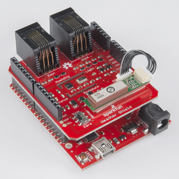
Shield on a RedBoard with optional weather meter connectors and GPS attached
Attach the GP-635T GPS module using the short cable. To secure the module, there is space on the shield to attach the module using double-stick tape.
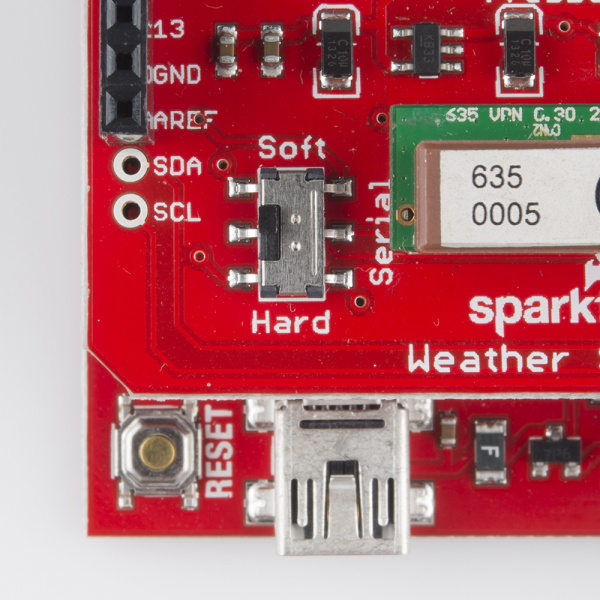
Serial pins are connected to digital pins 4 and 5 when Serial is set to soft and are attached to the internal UART when set to hard.
There is a switch labeled Serial on the shield. This is to select which pins on the Arduino to connect the GPS to. In almost all cases the switch should be set to ‘Soft’. This will attach the GPS serial pins to digital pins 5 (TX from the GPS) and 4 (RX into the GPS).
Grab the GPS example sketch that demonstrates using the GP-635T with all the other sensors. Load it onto your Arduino, and open the serial monitor at 9600. You should see output similar to the following:
$,winddir=-1,windspeedmph=nan,humidity=28.2,tempf=76.1,rainin=0.00,dailyrainin=0.00,pressure=81355.00,batt_lvl=4.05,light_lvl=3.05,lat=40.018054,lat=-105.282577,altitude=1647.40,sats=10,date=11/16/2013,time=20:00:44,#

$,winddir=-1,windspeedmph=nan,humidity=28.2,tempf=76.1,rainin=0.00,dailyrainin=0.00,pressure=81358.00,batt_lvl=4.07,light_lvl=3.05,lat=40.018054,lat=-105.282577,altitude=1647.40,sats=10,date=11/16/2013,time=20:00:45,#

$,winddir=-1,windspeedmph=nan,humidity=28.2,tempf=76.1,rainin=0.00,dailyrainin=0.00,pressure=81358.25,batt_lvl=4.08,light_lvl=3.05,lat=40.018054,lat=-105.282585,altitude=1647.40,sats=10,date=11/16/2013,time=20:00:46,#
Note: The batt_lvl is indicating 4.08V. This is correct and is the actual voltage read from the Arduino powered over USB. The GPS module will add 50-80mA to the overall power consumption. If you are using a long or thin USB cable you may see significant voltage drop similar to this example. There is absolutely no harm in this! The Weather Shield runs at 3.3V and the Arduino will continue to run just fine down to about 3V. The reading is very helpful for monitoring your power source (USB, battery, solar, etc).
This example demonstrates how you can get location, altitude, and time from the GPS module. This would be helpful with weather stations that are moving such as balloon satellites, AVL, package tracking, and even static stations where you need to know precise altitude or timestamps.
Resources and Going Further
The Weather Shield example firmware outputs regular barometric pressure. This is very different from the pressure that weather stations report. For more information, see the definition of “altimeter setting pressure”. For an example of how to calculate altimeter setting type barometric pressure see the MPL3115A2 hook-up guide. Also checkout the MPL3115A2 library, specifically the BarometricHgInch example.
Datasheets
There’s a lot of technology on this shield. Here’s the datasheets in case you need to reference them:
Additional resources and projects to checkout:
- HTU21D Humidity Repo and Library
- MPL3115A2 Pressure Repo and Library
- If you’re interested in using GPS with Arduino definitely checkout Mikal Hart’s TinyGPS++ library
- Consider adding an OpenLog for datalogging the weather readings over time
- Electric Imp is a good way to add WiFi to get a truly wireless weather station
learn.sparkfun.com |CC BY-SA 3.0 | SparkFun Electronics | Boulder, Colorado