RGB Panel Hookup Guide a learn.sparkfun.com tutorial
Introduction
Are you looking to add a lot of color to your project? These massive RGB LED panels are an awesome place to start. You can create animations, games, or all sorts of other fun displays with them.

A 16x32 RGB LED panel to the left, and a 32x32 panel to the right.
These panels come in two varieties: a 3.75x7.5"16x32 pixel panel:

And a 1024 pixel (3072 total LEDs!) 32x32 pixel panel measuring 7.5x7.5":
In this tutorial we’ll show you just how, exactly, these panels operate. We’ll dig into the hardware hookup and examine how to best power them. Then we’ll work up a demo sketch and control them with Arduino.
Required Materials
On top of either size panel, you’ll also need:
- At least an Arduino Uno (or comparable ATmega328-based Arduino). These panels really stretch the Arduino to its limits. If you have an Arduino Mega you may want to whip that out instead.
- Male-to-male jumper wires. You’ll need around 16 to wire from the panel to your Arduino.
- A 5V power supply. You’ll need something that can source a high amount of current. A simple 5V (1A) wall adapter does work, at least in the short run, but you may want to step up to a higher capacity supply, like these 12V/5V (2A) supplies.
- You’ll also need some method to connect your power supply to the panel. The panel includes a 4-pin polarized connector and spade-terminated cable for its power supply. Check out the next page for help finding a power source and cable.
Suggested Reading
Before following along with this tutorial, we recommend reading through these tutorials first:
- Light-Emitting Diodes (LEDs)
- What is an Arduino?
- Shift Registers
- Working with Wire
- How to Power a Project
Powering the Panel
These panels require a regulated 3.3-5V supply for power. And that supply needs to be able to source a good amount of current – up to 2A in the worst case (all pixels bright, hot, white). A white, 4-pin (2 for VCC, 2 for GND), 0.15"-pitch polarized connector should be used to supply power to the panel.

Included with the panel is a dedicated cable for power. It’s a 0.15" pitch 4-pin polarized connector. The included cable is terminated with both a female polarized connector, and a pair of spade terminals.

Here are a few methods we’ve used to power the panel:
Longer-Term: Power Supply
This is our recommended method. Combine:
- A 12V/5V 2A Power Supply, which should be enough to keep the display running at maximum capacity. (Just don’t hook up the 12V output to it!)
- An IEC C13 Cable to connect AC power to the supply.
- A 4-pin Molex Connector w/ Pigtail to interface the supply to panel.

The ingredients for our power supply and cable.
To begin, we snipped the spade connectors off of the panel power supply cable. And then stripped the newly unterminated ends.
Then we spliced the Molex pigtail to the LED panel’s power cable by connecting the red wires together. Do the same for the black wires (make sure you use the black wire next to the red on the Molex pigtail). Make sure you are connecting to the 5V and GND pins and NOT the 12V pin.

Finally, cover the splice with heat shrink or electrical tape, and voila! That’s a beautiful power cable.

Finished panel power supply cable.
This is a nice, sturdy interface between the panel and a solid power supply. If you’re looking for something easier, but less reliable check the below option.
Short-Term: Barrel Jack
A 5V 1A Wall Adapter or USB wall adapter (with USB barrel jack adapter) have both been tested to work with the panels as well. At least in the short term.

Use these in conjunction with a barrel jack adapter to get a quick and dirty connection between the spade and barrel jack.

Or you can make a more permanent solution with a panel mount connector.
All of that said, don’t use the 5V supply from your Arduino. Those are only spec'ed to supply about 800mA, and the Arduino’s already eating into that capacity a bit.
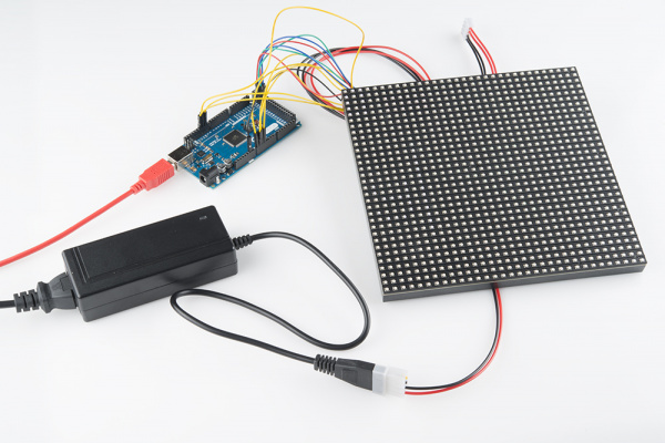
Hardware Hookup
Before we can get into the code portion, there’s quite a bit of wiring to do. Both the 32x16 and 32x32 panels have a pair of 16-pin (2x8) IDC connectors, and we need to wire up to most of those pins.
Conveniently, both panels have the connector pins labeled (the unlabeled pins are ground). As we’re hooking up to the panel, make sure you use the connector labeled Input.

Connector labels on a 32x32 panel. 16x32 has the same layout, except that D is a no connect (NC) instead.
Here are the pin connections between LED panel connector and Arduino:
| Panel Pin Label | Panel Connector Pin # | Arduino Pin | Notes |
|---|---|---|---|
| R0 | 1 | 2 | Red data (columns 1-16) |
| G0 | 2 | 3 | Green data (columns 1-16) |
| B0 | 3 | 4 | Blue data (columns 1-16) |
| GND | 4 | GND | Ground |
| R1 | 5 | 5 | Red data (columns 17-32) |
| G1 | 6 | 7 | Green data (columns 17-32) |
| B1 | 7 | 8 | Blue data (columns 17-32) |
| GND | 8 | GND | Ground |
| A | 9 | A0 | Demux input A0 |
| B | 10 | A1 | Demux input A1 |
| C | 11 | A2 | Demux input A2 |
| D | 12 | A3 | Demux input E1, E3 (32x32 panels only) |
| CLK | 13 | 11 | LED drivers' clock |
| STB | 14 | 10 | LED drivers' latch |
| OE | 15 | 9 | LED drivers' output enable |
| GND | 16 | GND | Ground |
Panel connector pin numbering convention: Pin 1 is top left (R0), pin 2 is to the right of pin 1, pin 3 is below pin 1, pin 4 is to the right of pin 3, etc. Pin 16 is the bottom right.
For a more step-by-step approach, follow along below. We use male-to-male jumper wires to wire between the included ribbon cable and our Arduino.
Data Pins: R0, B0, G0, R1, G1, and B1
These LED driver (shift register) data pins are hard-coded in the Arduino library and can’t be moved. R0, G0, B0, R1, G1, and B1 go to Arduino pins 2 through 7 respectively.
G0 → 3
B0 → 4
R1 → 5
G1 → 6
B1 → 7
When connecting into the ribbon cable connector, pay attention to the notch that signifies polarity. When looking at the cable with the notch facing up, R0 (pin 1) should be at the top left.

Both red and blue wires should be on the notch side, the greens should be on the other.
(Arduino Mega Note: If you’re wiring the panel up to an Arduino Mega, these pins should be connected to pins 24-29 respectively.)
Clock Pin
This is the last pin that has some restriction on where it can go – it must be connected to one of Arduino’s port B pins. That means it must be either 8, 9, 10, 11, 12, or 13. The example code has it wired up to pin 11.
A, B, C, (D for 32x32 users), OE, and STB
These five (or six if you’re using a 32x32 matrix) pins can be plugged in anywhere you may have space on your Arduino. Although, there’s probably not a lot of room left…
We chose to stick A, B, and C in pins A0, A1, and A2 respectively. OE connects to pin 9. STB to pin 10. And, if you’re using a 32x32 matrix, D goes to A3.
B → A1
C → A2
D → A3
OE → 9
STB → 10
Feel free to swap those up if your application requires. Just make sure you switch it up in the example code too.
Ground(s)
Last, but certainly not least (well, maybe, if we’re talking about potential) is ground. There are three unlabeled pins on the connector which should all be tied to ground.
If you don’t have anything else plugged into them, there should be three ground pins available on your Arduino. If you’re struggling to find ground pins, though, you should be able to get away with only plugging one of the ground pins to your Arduino.

Woo color coded wires!
Example Sketch
Install Arduino Libraries
Our example code is going to make use of Adafruit’s most excellent RGBMatrixPanel library, which also requires their AdafruitGFXLibrary. You can grab both from their GitHub repositories (see our Using GitHub tutorial for help downloading). Or click here to download a zip file of both folders.
Install the libraries into a libraries folder within your Arduino sketchbook. For more help installing libraries, check out our Installing an Arduino Library tutorial.
The RGBMatrixPanel library includes a number of fun examples to help show how the library can be used. They’re awesome. Check them out under the File>Examples>RGBMatrixPanel menu in Arduino. (Definitely check out the Plasma_32x32 or Plasma_16x32 examples!)
Serial Paint Example
We wanted to write another fun sketch that provided an interactive way to explore with the panels and the Arduino library. What we came up with is a Serial-controlled Paint program. With this sketch, you can use the serial monitor (or, better yet, another terminal program) to control a cursor and draw on the matrix.
Check out the codebender.cc embed below. If that doesn’t load for you, you can click here to download the sketch.
Before uploading, make sure the sketch is set up to work with your panel. If you’re using a 16x32 panel, you’ll need to make a few changes. Comment out this line (83):
RGBmatrixPanel matrix(A, B, C, D, CLK, LAT, OE, false); // 32x32
And uncomment this line (85):
RGBmatrixPanel matrix(A, B, C, CLK, LAT, OE, false); // 32x16
Also, 16x32 users should comment out the first bmp[] array in the bitmap.h file, and un-comment out the last.
Then upload! After upload, a single pixel should be blinking at the top left of the panel. It doesn’t look like much, but that’s a good sign.
Using the Sketch
To control the program, open up your serial terminal to 9600 bps. Try hitting sending l (lowercase ‘L’) through the serial monitor, which should load the demo bitmap. You can send E (uppercase) to erase the screen.
The idea of this sketch is: move the cursor around to draw pixels, shapes, or text. Here are the commands made available by the sketch (they are case-sensitive):
- Movement:
w,a,s,d(up, down, left, right) - Draw Pixel:
Spacebar - Erase Pixel:
e - Erase Screen:
E - Fill screen with active color:
f - Color Control:
- Red value up:
R(values between 0 [off] and 7 [most bright]) - Red value down:
r - Green up/down:
G/g - Blue up/down:
B/b - Copy color:
z(copies a color under the cursor)
- Red value up:
- Shape Drawing:
- Line: press
vto place starting point. Then move cursor to endpoint and pressvagain. - Rectangle: press
xorXto place first corner. Then move your cursor to where you want the diagonal corner. Then press eitherxfor an empty box, orXfor a filled box. - Circle: press
corCto place the center of the circle. Then move your cursor to where you want the outside edge of your circle to be. Then presscfor an empty circle orCfor a filled circle.
- Line: press
- Text: press
tto go to text mode. Now any characters received will be displayed on the panel. It’ll wrap around from one line to the next, but not from bottom to top. Press ``` (above Tab / left of 1) to exit text mode. - Print: press
pto print an array of your drawing to the serial terminal. You can copy this, and put it back in your sketch if you want to load it again. - Load: press
lto load a pre-defined array from the sketch. The sketch includes a demo array, which was created from the print command. Follow this example to load your own drawings!
Give the paint sketch a try! See if you can make the next great Lite-Brite LED Panel picture. If you make something neat, share it with us! Here are our creations:

An example drawing on the 32x32 panel.

A drawing on the 16x32 panel.
Don’t laugh. I drew that SFE flame one pixel at a time!
Resources & Going Further
Now that you know how to make use of these beautiful RGB LED matrices, what nifty project are you going to create with them? Here are some more resources, if you need them:
Going Further
If you’re looking for some inspiration, or more stuff to learn, check out these tutorials:
- Graphic LCD Hookup Guide– These little LCDs have a serious lack of color, but they’re very easy to control! And don’t require the crazy amounts of power our RGB matrices do.
- Serial Graphic LCD Hookup Guide– These LCDs continue with the monochrome theme, but they’re super easy-to-control. Instead of the dozen-or-so wires required to control the LCD, you only need one!
- LED Light Bar Hookup Guide– If super-bright LEDs are your thing, check out these LED light bars! If you just need a string of single color LEDs – whether you’re backlighting a project, or installing huge 7-segment LEDs – these make for an easy solution.
- Light– This tutorial is a bit more esoteric…but if you’re interested in the physics behind light, check out this tutorial.
learn.sparkfun.com |CC BY-SA 3.0 | SparkFun Electronics | Boulder, Colorado