Reaction Timer a learn.sparkfun.com tutorial
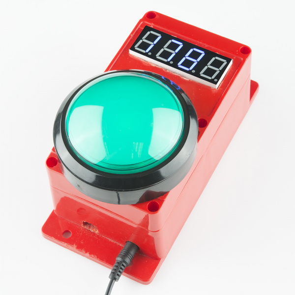
Push It!
Mental chronometry is the study of how fast humans react to different inputs. It takes a few hundred milliseconds for the signal to get from your eyes, to your brain, out to your limbs to respond. The reaction timer is a great project to demonstrate this time delay. It also makes for a fun game between friends!
It took 178ms to hit the button!
The principal of the reaction timer is simple: when the user sees the light turn on, press the button! A microcontroller is perfect for this because it can time milliseconds very accurately.
Required Materials
Here’s a list of parts used in this project:
- RedBoard
- Big Dome Push Button - Red
- OpenSegment Serial Display - 20mm (Blue)
- JST 3 Wire Assembly
- Enclosure - Flanged (Red)
- 5V Wall Adapter
Suggested Reading
This tutorial assumes you know a few things about Arduino and serial communication. If you’re a bit rusty consider checking out these tutorials:
Hardware
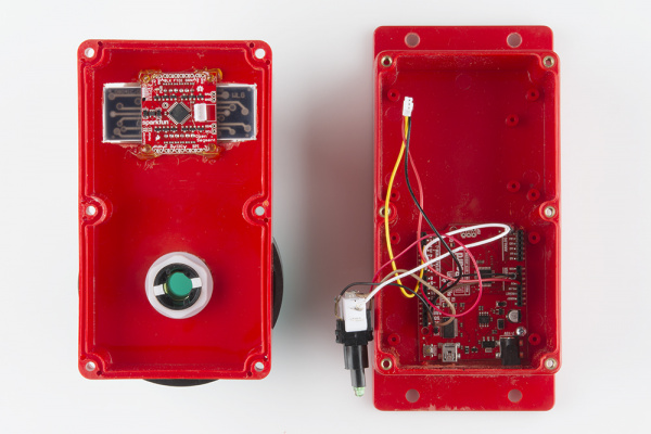
Guts of the Reaction Timer
The hardware is really simple. The RedBoard is connected to a large dome push button and an OpenSegment four-digit display. OpenSegment has a spot for a 3-pin JST, which makes it easy to connect on the fly. Checkout this page on the OpenSegment tutorial for more info.
One input (the button) and two outputs (the LED in the button and the time display) is all you need! We used jumper wires and simply plugged them into the RedBoard.
288ms is pretty slow!
This hardy red enclosure was used to withstand the endless button pounding. Cutting a hole for the dome button is pretty straight forward, and a dremel rotary tool easily cuts the slot for the 7-segment display. The edges are not very clean, but it was a quick project. If you wanted to get fancy, a printed graphic/bezel combo would provide instructions and give plenty of polish.
A few holes were drilled on the face that points down to allow for a USB cable and a power cable. The RedBoard is hotglued in place, the display is hotglued into the slot, and jumper wires provide the necessary connections. If this timer was being installed outside of SparkFun, we would solder and screw everything down, but this timer has survived quite a lot of abuse already!

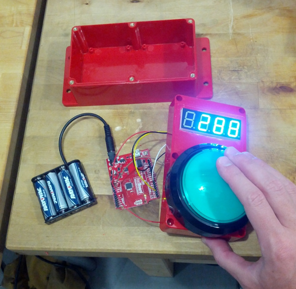
The final install
The unit can run off a battery pack for a few days, but, since we are permanently installing the timer near the kegerators at work, a 5V wall adapter provides all the power we need.
Firmware
The code that runs the reaction timer is very straight forward. We simply illuminate a light and wait for the user to press the button. You can grab the code here. A timer counts how many milliseconds it requires for the (slow, slow) human to respond. And, because we don’t want the human to cheat, we pick a random amount of time before we turn on the light.
Load this code onto the RedBoard, and open the terminal at 115200bps. You should see a series of debug statements such as ‘Games Played’ and ‘Err!’. For the full code see the Reaction Timer repo. If you are new to GitHub, visit our tutorial for more instructions.
Resources and Going Further
This project provides a really quick and solid example of how long it takes a human to react to visual stimulation. We’ve found that the average around the office is about 160ms, after the morning coffee has kicked in. Hopefully you can find parts of this project to use in your own timer or game.
You may also want to checkout:
- See the full reaction timer code on the github repo
- Bill Porter did a fantastic kids museum exhibit with graphics! Check his very cool Reaction Time Challenge Exhibit
- The Dice Gauntlet
- Using OpenSegment
- Switch Basics
- Connector Basics
- Battery Technologies
learn.sparkfun.com |CC BY-SA 3.0 | SparkFun Electronics | Boulder, Colorado