SIK Galileo - Part 9: Using a Flex Sensor a learn.sparkfun.com tutorial
Available online at: http://sfe.io/t283
Introduction
In this circuit, we will use a flex sensor to measure, well, flex! A flex sensor uses carbon on a strip of plastic to act like a variable resistor, but instead of changing the resistance by turning a knob, you change it by flexing (bending) the component. We use a “voltage divider” again to detect this change in resistance.
The sensor bends in one direction and the more it bends, the higher the resistance gets; it has a range from about 10K ohm to 35K ohm. In this circuit we will use the amount of bend of the flex sensor to control the position of a servo.
Parts Needed
You will need 1x flex sensor, 1x servo, 1x 10k resistor, and 11x jumper wires. If you are following through all of the SIK Galileo tutorials we suggest getting these parts:
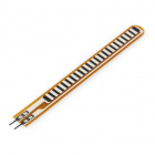
Flex Sensor 2.2"
SEN-10264A simple flex sensor 2.2" in length. As the sensor is flexed, the resistance across the sensor increases. Patented technology…

Servo - Generic (Sub-Micro Size)
ROB-09065Here is a simple, low-cost, high quality servo for all your mechatronic needs. This servo is very similar in size and specifi…

Jumper Wires Standard 7" M/M Pack of 30
PRT-11026If you need to knock up a quick prototype there's nothing like having a pile of jumper wires to speed things up, and let's fa…

Resistor 10K Ohm 1/6th Watt PTH - 20 pack
COM-115081/6th Watt, +/- 5% tolerance PTH resistors. Commonly used in breadboards and perf boards, these 10K resistors make excellent …
Suggested Reading
Before continuing on with this tutorial, we recommend you be somewhat familiar with the concepts in these tutorials:
Voltage Dividers
February 8, 2013
How to Use a Breadboard
May 14, 2013
Galileo Getting Started Guide
January 23, 2014
If you are following along with the SIK Galileo tutorials, it is helpful to view the tutorials before this one:
- SIK Galileo - Part 1: Blinking an LED
- SIK Galileo - Part 2: Reading a Potentiometer
- SIK Galileo - Part 3: Driving and RGB LED
- SIK Galileo - Part 4: Driving Multiple LEDs
- SIK Galileo - Part 5: Push Buttons
- SIK Galileo - Part 6: Reading a Photoresistor
- SIK Galileo - Part 7: Reading a Temperature Sensor
- SIK Galileo - Part 8: Driving a Servo Motor
Hardware Hookup
Ready to start hooking everything up? Check out the Fritzing diagram below, to see how everything is connected. Pay special attention to the component’s markings indicating how to place it on the breadboard. Polarized components can only be connected to a circuit in one direction.
Connect 3x jumper wires to the female 3 pin header on the servo. This will make it easier to breadboard the servo.

Having a hard time seeing the circuit? Click on the Fritzing diagram to see a bigger image. Please kept in mind your servo will have a white wire instead of yellow.
Code To Note
servoposition = map(flexposition, 600, 900, 0, 180);
map(value, fromLow, fromHigh, toLow, toHigh)
Because the flex sensor / resistor combination won’t give us a full 0 to 5 volt range, we’re using the map() function as a handy way to reduce that range. Here we’ve told it to only expect values from 600 to 900, rather than 0 to 1023.
servoposition = constrain(servoposition, 0, 180);
constrain(x, a, b)
Because map() could still return numbers outside the “to” range, we’ll also use a function called constrain() that will “clip” numbers into a range. If the number is outside the range, it will make it the largest or smallest number. If it is within the range, it will stay the same.
Copy and paste the following code into the Arduino IDE. Hit upload and see what happens!
language:cpp
/*
SparkFun Inventor's Kit Galileo
Example sketch 09

FLEX SENSOR

  Use the "flex sensor" to change the position of a servo

  In the previous sketch, we learned how to command a servo to
  mode to different positions. In this sketch, we'll introduce
  a new sensor, and use it to control the servo.

  A flex sensor is a plastic strip with a conductive coating.
  When the strip is straight, the coating will be a certain
  resistance. When the strip is bent, the particles in the coating
  get further apart, increasing the resistance. You can use this
  sensor to sense finger movement in gloves, door hinges, stuffed
  animals, etc. See http://www.sparkfun.com/tutorials/270 for
  more information.

Hardware connections:

  Flex sensor:

    The flex sensor is the plastic strip with black stripes.
    It senses bending away from the striped side.

    The flex sensor has two pins, and since it's a resistor,
    the pins are interchangable.

    Connect one of the pins to ANALOG IN pin 0 on the Arduino.
    Connect the same pin, through a 10K Ohm resistor (brown
    black orange) to GND.
    Connect the other pin to 5V.

  Servo:

    The servo has a cable attached to it with three wires.
    Because the cable ends in a socket, you can use jumper wires
    to connect between the Arduino and the servo. Just plug the
    jumper wires directly into the socket.

    Connect the RED wire (power) to 5 Volts (5V)
    Connect the WHITE wire (signal) to digital pin 9
    Connect the BLACK wire (ground) to ground (GND)

    Note that servos can use a lot of power, which can cause your
    Arduino to reset or behave erratically. If you're using large
    servos or many of them, it's best to provide them with their
    own separate 5V supply. See this Arduino Forum thread for info:
    http://www.arduino.cc/cgi-bin/yabb2/YaBB.pl?num=1239464763

This sketch was written by SparkFun Electronics,
with lots of help from the Arduino community.
This code is completely free for any use.
Visit http://learn.sparkfun.com/products/2 for SIK information.
Visit http://www.arduino.cc to learn about the Arduino.

Version 2.0 6/2012 MDG
*/


// Include the servo library to add servo-control functions:

#include <Servo.h>

// Create a servo "object", called servo1. Each servo object
// controls one servo (you can have a maximum of 12):

Servo servo1;

// Define the analog input pin to measure flex sensor position:

const int flexpin = 0;


void setup()
{
  // Use the serial monitor window to help debug our sketch:

  Serial.begin(9600);

  // Enable control of a servo on pin 9:

  servo1.attach(9);
}


void loop()
{
  int flexposition;    // Input value from the analog pin.
  int servoposition;   // Output value to the servo.

  // Read the position of the flex sensor (0 to 1023):

  flexposition = analogRead(flexpin);

  // Because the voltage divider circuit only returns a portion
  // of the 0-1023 range of analogRead(), we'll map() that range
  // to the servo's range of 0 to 180 degrees. The flex sensors
  // we use are usually in the 600-900 range:

  servoposition = map(flexposition, 600, 900, 0, 180);
  servoposition = constrain(servoposition, 0, 180);

  // Now we'll command the servo to move to that position:

  servo1.write(servoposition);

  // Because every flex sensor has a slightly different resistance,
  // the 600-900 range may not exactly cover the flex sensor's
  // output. To help tune our program, we'll use the serial port to
  // print out our values to the serial monitor window:

  Serial.print("sensor: ");
  Serial.print(flexposition);
  Serial.print("  servo: ");
  Serial.println(servoposition);

  // Note that all of the above lines are "print" except for the
  // last line which is "println". This puts everything on the
  // same line, then sends a final carriage return to move to
  // the next line.

  // After you upload the sketch, turn on the serial monitor
  // (the magnifying-glass icon to the right of the icon bar).
  // You'll be able to see the sensor values. Bend the flex sensor
  // and note its minimum and maximum values. If you replace the
  // 600 and 900 in the map() function above, you'll exactly match
  // the flex sensor's range with the servo's range.

  delay(20);  // wait 20ms between servo updates
}
What You Should See
You should see the servo motor move in accordance with how much you are flexing the flex sensor. If it isn’t working, make sure you have assembled the circuit correctly and verified and uploaded the code to your board or see the troubleshooting section.

Real World Application:
Controller accessories for video game consoles like Nintendo’s “Power Glove” use flex-sensing technology. It was the first video game controller attempting to mimic hand movement on a screen in real time.
Troubleshooting
Servo Not Twisting
Even with colored wires it is still shockingly easy to plug a servo in backwards. This might be the case.
Servo Not Moving as Expected
The sensor is only designed to work in one direction. Try flexing it the other way (where the striped side faces out on a convex curve).
Servo Doesn’t Move very Far
You need to modify the range of values in the call to the map() function.
Resources and Going Further
Ready to continue? Have fun learning about the Galileo and continue along through all the SIK Galileo tutorials.
- SIK Galileo - Part 10: Reading a Soft Potentiometer
- SIK Galileo - Part 11: Using a Piezo Buzzer
- SIK Galileo - Part 12: Driving a Motor
- SIK Galileo - Part 13: Using Relays
- SIK Galileo - Part 14: Using a Shift Register
- SIK Galileo - Part 15: Using an LCD
learn.sparkfun.com |CC BY-SA 3.0 | SparkFun Electronics | Niwot, Colorado