SIK Galileo - Part 12: Driving a Motor a learn.sparkfun.com tutorial
Available online at: http://sfe.io/t286
Introduction
Back in Circuit 8, you got to work with a servo motor. Now, we are going to tackle spinning a motor. This requires the use of a transistor, which can switch a larger amount of current than the Galileo can.
When using a transistor, you just need to make sure its maximum specs are high enough for your use case. The transistor we are using for this circuit is rated at 40V max and 200 milliamps max – perfect for our toy motor! When the motor is spinning and suddenly turned off, the magnetic field inside it collapses, generating a voltage spike. This can damage the transistor. To prevent this, we use a “flyback diode”, which diverts the voltage spike around the transistor.
Parts Needed
You will need 1x motor, 1x NPN transistor, 1x diode 1N4148, 1x 330Ω resistor, and 6x jumper wires. If you are following through all of the SIK Galileo tutorials we suggest getting these parts:
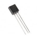
Transistor - NPN (P2N2222A)
COM-12852This is the P2N2222A, an NPN silicon BJT (Bipolar Junction Transistor). This little transistor can help in your project by be…

Jumper Wires Standard 7" M/M Pack of 30
PRT-11026If you need to knock up a quick prototype there's nothing like having a pile of jumper wires to speed things up, and let's fa…

Resistor 330 Ohm 1/6 Watt PTH - 20 pack
COM-115071/6 Watt, +/- 5% tolerance PTH resistors. Commonly used in breadboards and perf boards, these 330Ohm resistors make excellent…
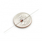
Diode Small Signal - 1N4148
COM-08588This is a very common signal diode - 1N4148. Use this for signals up to 200mA of current. If you need a bunch of these, you…
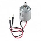
Hobby Motor - Gear
ROB-11696This is our new Hobby Motor now with a 6mm, 10 tooth, gear to make your basic projects a little simpler to manage. It works w…
Suggested Reading
Before continuing on with this tutorial, we recommend you be somewhat familiar with the concepts in these tutorials:
How to Use a Breadboard
May 14, 2013
Diodes
May 9, 2013
Galileo Getting Started Guide
January 23, 2014
Transistors
July 1, 2014
If you are following along with the SIK Galileo tutorials, it is helpful to view the tutorials before this one:
- SIK Galileo - Part 1: Blinking an LED
- SIK Galileo - Part 2: Reading a Potentiometer
- SIK Galileo - Part 3: Driving and RGB LED
- SIK Galileo - Part 4: Driving Multiple LEDs
- SIK Galileo - Part 5: Push Buttons
- SIK Galileo - Part 6: Reading a Photoresistor
- SIK Galileo - Part 7: Reading a Temperature Sensor
- SIK Galileo - Part 8: Driving a Servo Motor
- SIK Galileo - Part 9: Using a Flex Sensor
- SIK Galileo - Part 10: Reading a Soft Potentiometer
- SIK Galileo - Part 11: Using a Piezo Buzzer
Hardware Hookup
Ready to start hooking everything up? Check out the Fritzing diagram below, to see how everything is connected. Pay special attention to the component’s markings indicating how to place it on the breadboard. Polarized components can only be connected to a circuit in one direction.
Please note: When you’re building the circuit be careful not to mix up the transistor and the temperature sensor, they’re almost identical. Look for “P2N2222A” on the body of the transistor.
Fritzing Diagram

Having a hard time seeing the circuit? Click on the Fritzing diagram to see a bigger image.
Code To Note
while (Serial.available() > 0)
The Galileo’s serial port can be used to receive as well as send data. Because data could arrive at any time, the Galileostores, or “buffers” data coming into the port until you’re ready to use it. The Serial.available() command returns the number of characters that the port has received, but haven’t been used by your sketch yet. Zero means no data has arrived.
speed = Serial.parseInt();
If the port has data waiting for you, there are a number of ways for you to use it. Since we’re typing numbers into the port, we can use the handy Serial.parseInt() command to extract, or “parse” integer numbers from the characters it’s received. If you type “1” “0” “0” to the port, this function will return the number 100.
Copy and paste the following code into the Arduino IDE. Hit upload and see what happens!
language:cpp
/*
SparkFun Inventor's Kit Galileo
Example sketch 12

SPINNING A MOTOR

  Use a transistor to spin a motor at different speeds.
  We'll also show you how to input data from the serial port
  (see the serialSpeed() function below).

  Motors are the basis for thousands of things in our daily lives,
  and the Arduino can control them. Here we'll use pulse-width
  modulation (PWM) to vary the speed of a motor.

  The Arduino pins are strong enough to light small LEDs (up to
  40 milliAmps), but they're not strong enough to run motors and
  other power-hungry parts. (This motor needs 50-100mA).
  Because the motor needs more current than an Arduino pin can
  provide, we'll use a transistor to do the heavy lifting.
  A transistor is a solid-state switch. When we give it a small
  amount of current, it can switch a much larger current.
  The transistors in your kit (2N2222) can switch up to 200mA.

  You can turn a transistor on and off using the digitalWrite()
  function, but you can also use the analogWrite() function to
  vary the speed of the motor. The analogWrite() function pulses
  a pin, varying the width of the pulse from 0% to 100%. We call
  this technique "PWM", for "Pulse-Width Modulation".

  One thing to keep in mind is that when you lower the speed of
  a motor using PWM, you're also reducing the torque (strength)
  of the motor. For PWM values below 50 or so, the motor won't have
  enough torque to start spinning. It will start spinning when you
  raise the speed a bit.

Hardware connections:

  Transistor:

    The transistor has three pins. Looking at the flat side with the
    pins down, the order is COLLECTOR, BASE, EMITTER.

    Connect the black wire on the motor to the
    COLLECTOR pin on the transistor.

    Connect the BASE pin through a 330 Ohm resistor to
    digital pin 9.

    Connect the EMITTER pin to GND.

  Motor:

    You've already connected the black wire on the motor to the
    COLLECTOR pin on the transistor.

    Connect the other (red) wire on the motor to 5V.

  Flyback diode:

    When the motor is spinning and suddenly turned off, the
    magnetic field inside it collapses, generating a voltage spike.
    This can damage the transistor. To prevent this, we use a
    "flyback diode", which diverts the voltage spike "around" the
    transistor.

    Connect the side of the diode with the band (cathode) to 5V
    Connect the other side of the diode (anode) to the black wire
    on the motor.

This sketch was written by SparkFun Electronics,
with lots of help from the Arduino community.
This code is completely free for any use.
Visit http://learn.sparkfun.com/products/2 for SIK information.
Visit http://www.arduino.cc to learn about the Arduino.

Version 2.0 6/2012 MDG
*/

// We'll be controlling the motor from pin 9.
// This must be one of the PWM-capable pins.

const int motorPin = 9;


void setup()
{
  // Set up the motor pin to be an output:

  pinMode(motorPin, OUTPUT);

  // Set up the serial port:

  Serial.begin(9600);
}


void loop()
{
  // Here we've used comments to disable some of the examples.
  // To try different things, uncomment one of the following lines
  // and comment the other ones. See the functions below to learn
  // what they do and how they work.

  // motorOnThenOff();
  // motorOnThenOffWithSpeed();
  // motorAcceleration();
     serialSpeed();
}


// This function turns the motor on and off like the blinking LED.
// Try different values to affect the timing.

void motorOnThenOff()
{
  int onTime = 3000;  // milliseconds to turn the motor on
  int offTime = 3000; // milliseconds to turn the motor off

  digitalWrite(motorPin, HIGH); // turn the motor on (full speed)
  delay(onTime);                // delay for onTime milliseconds
  digitalWrite(motorPin, LOW);  // turn the motor off
  delay(offTime);               // delay for offTime milliseconds
}


// This function alternates between two speeds.
// Try different values to affect the timing and speed.

void motorOnThenOffWithSpeed()
{
  int Speed1 = 200;  // between 0 (stopped) and 255 (full speed)
  int Time1 = 3000;  // milliseconds for speed 1

  int Speed2 = 50;   // between 0 (stopped) and 255 (full speed)
  int Time2 = 3000;  // milliseconds to turn the motor off

  analogWrite(motorPin, Speed1);  // turns the motor On
  delay(Time1);                   // delay for onTime milliseconds
  analogWrite(motorPin, Speed2);  // turns the motor Off
  delay(Time2);                   // delay for offTime milliseconds
}


// This function slowly accelerates the motor to full speed,
// then back down to zero.

void motorAcceleration()
{
  int speed;
  int delayTime = 20; // milliseconds between each speed step

  // accelerate the motor

  for(speed = 0; speed <= 255; speed++)
  {
    analogWrite(motorPin,speed);    // set the new speed
    delay(delayTime);               // delay between speed steps
  }

  // decelerate the motor

  for(speed = 255; speed >= 0; speed--)
  {
    analogWrite(motorPin,speed);    // set the new speed
    delay(delayTime);               // delay between speed steps
  }
}


// This function will let you type a speed into the serial
// monitor window. Open the serial monitor using the magnifying-
// glass icon at the top right of the Arduino window. Then
// type your desired speed into the small text entry bar at the
// top of the window and click "Send" or press return. The motor
// will then operate at that speed. The valid range is 0 to 255.

void serialSpeed()
{
  int speed;

  Serial.println("Type a speed (0-255) into the box above,");
  Serial.println("then click [send] or press [return]");
  Serial.println();  // Print a blank line

  // In order to type out the above message only once,
  // we'll run the rest of this function in an infinite loop:

  while(true)  // "true" is always true, so this will loop forever.
  {
    // First we check to see if incoming data is available:

    while (Serial.available() > 0)
    {
      // If it is, we'll use parseInt() to pull out any numbers:

      speed = Serial.parseInt();

      // Because analogWrite() only works with numbers from
      // 0 to 255, we'll be sure the input is in that range:

      speed = constrain(speed, 0, 255);

      // We'll print out a message to let you know that the
      // number was received:

      Serial.print("Setting speed to ");
      Serial.println(speed);

      // And finally, we'll set the speed of the motor!

      analogWrite(motorPin, speed);
    }
  }
}
What You Should See
The DC Motor should spin if you have assembled the circuit’s components correctly, and also verified/uploaded the correct code. If your circuit is not working check the troubleshooting section.

Real World Application:
Radio Controlled (RC) cars use Direct Current (DC) motors to turn the wheels for propulsion.
Troubleshooting
Motor Not Spinning
If you sourced your own transistor, double check with the data sheet that the pinout is compatible with a P2N2222AG (many are reversed).
Still No Luck
If you sourced your own motor, double check that it will work with 5 volts and that it does not draw too much power.
Still Not Working
Sometimes the Galileo will disconnect from the computer. Try un-plugging and then re-plugging it into your USB port.
Resources and Going Further
Ready to continue? Have fun learning about the Galileo and continue along through all the SIK Galileo tutorials.
- SIK Galileo - Part 13: Using Relays
- SIK Galileo - Part 14: Using a Shift Register
- SIK Galileo - Part 15: Using an LCD
learn.sparkfun.com |CC BY-SA 3.0 | SparkFun Electronics | Niwot, Colorado