SIK Galileo - Part 14: Using a Shift Register a learn.sparkfun.com tutorial
Available online at: http://sfe.io/t288
Introduction
Now we are going to step into the world of ICs (integrated circuits). In this circuit, you’ll learn all about using a shift register (also called a serial-to-parallel converter). The shift register will give your Galileo an additional eight outputs, using only three pins on your board. For this circuit, you’ll practice by using the shift register to control eight LEDs.
Parts Needed
You will need 1x shift register 8-Bit - 74HC595, 8x LED, 8x 330Ω resistor, and 19x jumper wires. If you are following through all of the SIK Galileo tutorials we suggest getting these parts:

Jumper Wires Standard 7" M/M Pack of 30
PRT-11026If you need to knock up a quick prototype there's nothing like having a pile of jumper wires to speed things up, and let's fa…

Resistor 330 Ohm 1/6 Watt PTH - 20 pack
COM-115071/6 Watt, +/- 5% tolerance PTH resistors. Commonly used in breadboards and perf boards, these 330Ohm resistors make excellent…
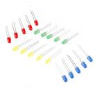
LED - Assorted (20 pack)
COM-12062We all know that you can never get too many LEDs. Don't worry, we've got you covered. This is a pack of basic red, yellow, bl…
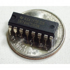
Shift Register 8-Bit - 74HC595
COM-00733Simple shift register IC. Clock in data and latch it to free up IO pins on your micro. Check out this [tutorial](http://dln…
Suggested Reading
Before continuing on with this tutorial, we recommend you be somewhat familiar with the concepts in these tutorials:
How to Use a Breadboard
May 14, 2013
Shift Registers
August 23, 2013
Integrated Circuits
July 15, 2013
Galileo Getting Started Guide
January 23, 2014
If you are following along with the SIK Galileo tutorials, it is helpful to view the tutorials before this one:
- SIK Galileo - Part 1: Blinking an LED
- SIK Galileo - Part 2: Reading a Potentiometer
- SIK Galileo - Part 3: Driving and RGB LED
- SIK Galileo - Part 4: Driving Multiple LEDs
- SIK Galileo - Part 5: Push Buttons
- SIK Galileo - Part 6: Reading a Photoresistor
- SIK Galileo - Part 7: Reading a Temperature Sensor
- SIK Galileo - Part 8: Driving a Servo Motor
- SIK Galileo - Part 9: Using a Flex Sensor
- SIK Galileo - Part 10: Reading a Soft Potentiometer
- SIK Galileo - Part 11: Using a Piezo Buzzer
- SIK Galileo - Part 12: Driving a Motor
- SIK Galileo - Part 13: Using Relays
Hardware Hookup
Ready to start hooking everything up? Check out the Fritzing diagram below, to see how everything is connected. Pay special attention to the component’s markings indicating how to place it on the breadboard. Polarized components can only be connected to a circuit in one direction.
For the shift register, align notch on top, in-between “e1” and “f1” on the breadboard. The notch indicates where pin 1 is.
Fritzing Diagram

Having a hard time seeing the circuit? Click on the Fritzing diagram to see a bigger image.
Code To Note
shiftOut(datapin, clockpin, MSBFIRST, data);
You’ll communicate with the shift register (and a lot of other parts) using an interface called SPI, or Serial Peripheral Interface. This interface uses a data line and a separate clock line that work together to move data in or out of the Galileo at high speed. The MSBFIRST parameter specifies the order in which to send the individual bits, in this case we’re sending the Most Significant Bit first.
bitWrite(data, desiredPin, desiredState);
Bits are the smallest possible piece of memory in a computer; each one can store either a “1” or a “0”. Larger numbers are stored as arrays of bits. Sometimes we want to manipulate these bits directly, for example now when we’re sending eight bits to the shift register and we want to make them 1 or 0 to turn the LEDs on or off. The Galileo has several commands, such as bitWrite(), that make this easy to do.
Copy and paste the following code into the Arduino IDE. Hit upload and see what happens!
language:cpp
/*
SparkFun Inventor's Kit Galileo
Example sketch 13

SHIFT REGISTER

  Use a shift register to turn three pins into eight (or more!)
  outputs

  An integrated circuit ("IC"), or "chip", is a self-contained
  circuit built into a small plastic package. (If you look closely
  at your Arduino board you'll see a number of ICs.) There are
  thousands of different types of ICs available that you can use
  to perform many useful functions.

  The 74HC595 shift register in your kit is an IC that has eight
  digital outputs. To use these outputs, we'll use a new interface
  called SPI (Serial Peripheral Interface). It's like the TX and
  RX you're used to, but has an additional "clock" line that
  controls the speed of the data transfer. Many parts use SPI
  for communications, so the Arduino offers simple commands called
  shiftIn() and shiftOut() to access these parts.

  This IC lets you use three digital pins on your Arduino to
  control eight digital outputs on the chip. And if you need
  even more outputs, you can daisy-chain multiple shift registers
  together, allowing an almost unlimited number of outputs from
  the same three Arduino pins! See the shift register datasheet
  for details:

  http://www.sparkfun.com/datasheets/IC/SN74HC595.pdf

Hardware connections:

  Shift register:

    Plug in the chip so it bridges the center "canyon"
    on the breadboard.

    The shift register has 16 pins. They are numbered
    counterclockwise starting at the pin 1 mark (notch
    in the end of the chip). See the datasheet above
    for a diagram.

    74HC595 pin     LED pin     Arduino pin

    1  (QB)     LED 2 +
    2  (QC)     LED 3 +
    3  (QD)     LED 4 +
    4  (QE)     LED 5 +
    5  (QF)     LED 6 +
    6  (QG)     LED 7 +
    7  (QH)     LED 8 +
    8  (GND)                GND

    9  (QH*)
    10 (SRCLR*)             5V
    11 (SRCLK)              Digital 3
    12 (RCLK)               Digital 4
    13 (OE*)                GND
    14 (SER)                Digital 2
    15 (QA)     LED 1 +
    16 (VCC)                5V

  LEDs:

    After making the above connections to the positive (longer)
    legs of the LEDs, connect the negative side (short lead) of
    each LED to a 330 Ohm resistor, and connect the other side
    of each resistor to GND.

This sketch was written by SparkFun Electronics,
with lots of help from the Arduino community.
This code is completely free for any use.
Visit http://learn.sparkfun.com/products/2 for SIK information.
Visit http://www.arduino.cc to learn about the Arduino.

Version 2.0 6/2012 MDG
*/


// Pin definitions:
// The 74HC595 uses a type of serial connection called SPI
// (Serial Peripheral Interface) that requires three pins:

int datapin = 2;
int clockpin = 3;
int latchpin = 4;

// We'll also declare a global variable for the data we're
// sending to the shift register:

byte data = 0;


void setup()
{
  // Set the three SPI pins to be outputs:

  pinMode(datapin, OUTPUT);
  pinMode(clockpin, OUTPUT);
  pinMode(latchpin, OUTPUT);
}


void loop()
{
  // We're going to use the same functions we played with back
  // in circuit 04, "Multiple LEDs", we've just replaced
  // digitalWrite() with a new function called shiftWrite()
  // (see below). We also have a new function that demonstrates
  // binary counting.

  // To try the different functions below, uncomment the one
  // you want to run, and comment out the remaining ones to
  // disable them from running.

  oneAfterAnother();      // All on, all off

  //oneOnAtATime();       // Scroll down the line

  //pingPong();           // Like above, but back and forth

  //randomLED();          // Blink random LEDs

  //marquee();

  //binaryCount();        // Bit patterns from 0 to 255
}


void shiftWrite(int desiredPin, boolean desiredState)

// This function lets you make the shift register outputs
// HIGH or LOW in exactly the same way that you use digitalWrite().

// Like digitalWrite(), this function takes two parameters:

//    "desiredPin" is the shift register output pin
//    you want to affect (0-7)

//    "desiredState" is whether you want that output
//    to be HIGH or LOW

// Inside the Arduino, numbers are stored as arrays of "bits",
// each of which is a single 1 or 0 value. Because a "byte" type
// is also eight bits, we'll use a byte (which we named "data"
// at the top of this sketch) to send data to the shift register.
// If a bit in the byte is "1", the output will be HIGH. If the bit
// is "0", the output will be LOW.

// To turn the individual bits in "data" on and off, we'll use
// a new Arduino commands called bitWrite(), which can make
// individual bits in a number 1 or 0.
{
  // First we'll alter the global variable "data", changing the
  // desired bit to 1 or 0:

  bitWrite(data,desiredPin,desiredState);

  // Now we'll actually send that data to the shift register.
  // The shiftOut() function does all the hard work of
  // manipulating the data and clock pins to move the data
  // into the shift register:

  shiftOut(datapin, clockpin, MSBFIRST, data);

  // Once the data is in the shift register, we still need to
  // make it appear at the outputs. We'll toggle the state of
  // the latchPin, which will signal the shift register to "latch"
  // the data to the outputs. (Latch activates on the high-to
  // -low transition).

  digitalWrite(latchpin, HIGH);
  digitalWrite(latchpin, LOW);
}


/*
oneAfterAnother()

This function will light one LED, delay for delayTime, then light
the next LED, and repeat until all the LEDs are on. It will then
turn them off in the reverse order.
*/

void oneAfterAnother()
{
  int index;
  int delayTime = 100; // Time (milliseconds) to pause between LEDs
                       // Make this smaller for faster switching

  // Turn all the LEDs on:

  // This for() loop will step index from 0 to 7
  // (putting "++" after a variable means add one to it)
  // and will then use digitalWrite() to turn that LED on.

  for(index = 0; index <= 7; index++)
  {
    shiftWrite(index, HIGH);
    delay(delayTime);
  }

  // Turn all the LEDs off:

  // This for() loop will step index from 7 to 0
  // (putting "--" after a variable means subtract one from it)
  // and will then use digitalWrite() to turn that LED off.

  for(index = 7; index >= 0; index--)
  {
    shiftWrite(index, LOW);
    delay(delayTime);
  }
}


/*
oneOnAtATime()

This function will step through the LEDs, lighting one at at time.
*/

void oneOnAtATime()
{
  int index;
  int delayTime = 100; // Time (milliseconds) to pause between LEDs
                       // Make this smaller for faster switching

  // step through the LEDs, from 0 to 7

  for(index = 0; index <= 7; index++)
  {
    shiftWrite(index, HIGH);    // turn LED on
    delay(delayTime);       // pause to slow down the sequence
    shiftWrite(index, LOW); // turn LED off
  }
}


/*
pingPong()

This function will step through the LEDs, lighting one at at time,
in both directions.
*/

void pingPong()
{
  int index;
  int delayTime = 100; // time (milliseconds) to pause between LEDs
                       // make this smaller for faster switching

  // step through the LEDs, from 0 to 7

  for(index = 0; index <= 7; index++)
  {
    shiftWrite(index, HIGH);    // turn LED on
    delay(delayTime);       // pause to slow down the sequence
    shiftWrite(index, LOW); // turn LED off
  }

  // step through the LEDs, from 7 to 0

  for(index = 7; index >= 0; index--)
  {
    shiftWrite(index, HIGH);    // turn LED on
    delay(delayTime);       // pause to slow down the sequence
    shiftWrite(index, LOW); // turn LED off
  }
}


/*
randomLED()

This function will turn on random LEDs. Can you modify it so it
also lights them for random times?
*/

void randomLED()
{
  int index;
  int delayTime = 100; // time (milliseconds) to pause between LEDs
                       // make this smaller for faster switching

  // The random() function will return a semi-random number each
  // time it is called. See http://arduino.cc/en/Reference/Random
  // for tips on how to make random() more random.

  index = random(8);    // pick a random number between 0 and 7

  shiftWrite(index, HIGH);  // turn LED on
  delay(delayTime);     // pause to slow down the sequence
  shiftWrite(index, LOW);   // turn LED off
}


/*
marquee()

This function will mimic "chase lights" like those around signs.
*/

void marquee()
{
  int index;
  int delayTime = 200; // Time (milliseconds) to pause between LEDs
                       // Make this smaller for faster switching

  // Step through the first four LEDs
  // (We'll light up one in the lower 4 and one in the upper 4)

  for(index = 0; index <= 3; index++)
  {
    shiftWrite(index, HIGH);    // Turn a LED on
    shiftWrite(index+4, HIGH);  // Skip four, and turn that LED on
    delay(delayTime);       // Pause to slow down the sequence
    shiftWrite(index, LOW); // Turn both LEDs off
    shiftWrite(index+4, LOW);
  }
}


/*
binaryCount()

Numbers are stored internally in the Arduino as arrays of "bits",
each of which is a 1 or 0. Just like the base-10 numbers we use
every day, The position of the bit affects the magnitude of its
contribution to the total number:

Bit position   Contribution
0              1
1              2
2              4
3              8
4              16
5              32
6              64
7              128

To build any number from 0 to 255 from the above 8 bits, just
select the contributions you need to make. The bits will then be
1 if you use that contribution, and 0 if you don't.

This function will increment the "data" variable from 0 to 255
and repeat. When we send this value to the shift register and LEDs,
you can see the on-off pattern of the eight bits that make up the
byte. See http://www.arduino.cc/playground/Code/BitMath for more
information on binary numbers.
*/

void binaryCount()
{
  int delayTime = 1000; // time (milliseconds) to pause between LEDs
                        // make this smaller for faster switching

  // Send the data byte to the shift register:

  shiftOut(datapin, clockpin, MSBFIRST, data);

  // Toggle the latch pin to make the data appear at the outputs:

  digitalWrite(latchpin, HIGH);
  digitalWrite(latchpin, LOW);

  // Add one to data, and repeat!
  // (Because a byte type can only store numbers from 0 to 255,
  // if we add more than that, it will "roll around" back to 0
  // and start over).

  data++;

  // Delay so you can see what's going on:

  delay(delayTime);
}
What You Should See
You should see the LEDs light up similarly to SIK Galileo - Part 4 (but this time, you’re using a shift register). If they aren’t, make sure you have assembled the circuit correctly and verified and uploaded the code to your board. See the troubleshooting section.

Real World Application:
Similar to SIK Galileo - Part 4, a scrolling marquee display delivers a message with multiple LEDs. Essentially the same task the shift register achieves here in SIK Galileo - Part 14.
Troubleshooting
The Galileo’s power LED goes out
This happened to us a couple of times, it happens when the chip is inserted backward. If you fix it quickly nothing will break.
Not Quite Working
Sorry to sound like a broken record but it is probably something as simple as a crossed wire.
Frustration
Shoot us an e-mail, this circuit is both simple and complex at the same time. We want to hear about problems you have so we can address them in future editions: techsupport@sparkfun.com
Resources and Going Further
Ready to continue? Have fun learning about the Galileo and continue along through all the SIK Galileo tutorials.
learn.sparkfun.com |CC BY-SA 3.0 | SparkFun Electronics | Niwot, Colorado