Large Digit Driver Hookup Guide a learn.sparkfun.com tutorial
Available online at: http://sfe.io/t368
Introduction
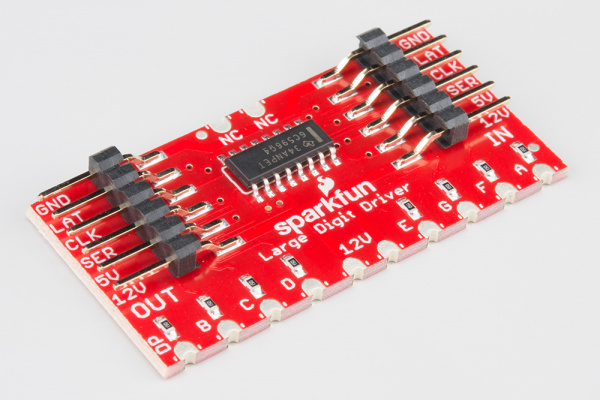
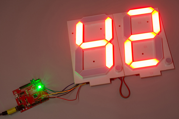
Large numerical displays are a great addition to any project where you want to be able to see information at a distance. Scorekeepers and lap timers would be a great application for large 7-segment LED displays. The Really Big 7-Segment Display (6.5") fits that bill nicely. Driving several displays at the same time would be handy, which is where the Large Digit Driver board comes in.
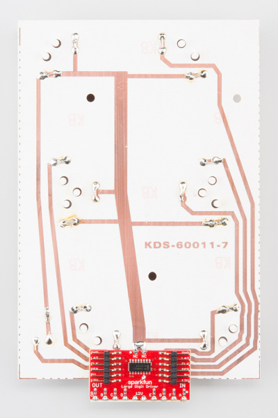
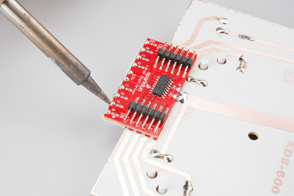
The Large Digit Driver can be soldered directly to the bottom of the 7-Segment Display.
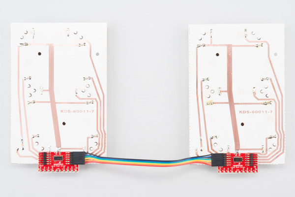
Several Large Digit Drivers can be chained together to create a display with multiple digits.
Covered in This Tutorial
In this tutorial, we will give you an overview of the Large Digit Driver and provide an example of hooking up the driver to an Arduino:
- Board Overview– To begin, we’ll go over each of the pins on the breakout board and their function.
- Hardware Hookup– In this section, we’ll show you how to hook the Large Digit Driver up to an Arduino.
- Example: One Large Digit– Here, we give an example of an Arduino sketch to control one of the large 7-segment displays through the Large Digit Driver.
- Example: Two Large Digits– We show how to daisy chain two large 7-segment displays together and control them with two Large Digit Drivers.
- Resources and Going Further– This section gives some additional resources for getting more out of the Large Digit Driver.
Materials Used
You will need a few components and tools to follow along with this tutorial. Here is what you will need:
For each additional digit you want to add, you will need:
Recommended Reading
Before getting started with the Large Digit Driver, there are a few concepts that you should be familiar with. Consider reading some of these tutorials before continuing:
- What is an Arduino?– We will use an Arduino to control the Large Digit Driver
- Shift Registers– The Large Digit Driver uses a shift register to move data to each digit
- How to Solder - Castellated Mounting Holes– You will need to solder the Large Digit Driver to the back of the 7-segment LED display
Board Overview
Pin Descriptions
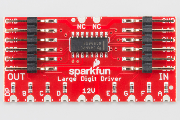
The Large Digit Driver has 6 input pins and 6 output pins.
| IN Pin | Description |
|---|---|
| GND | Connect to ground |
| LAT | Data transfer in from SER on the rising edge of the latch pin |
| CLK | Data transfer in from SER on the rising edge of the clock pin |
| SER | Serial data in |
| 5V | Connect to power (5V) |
| 12V | Connect to power (12V) |
| OUT Pin | Description |
|---|---|
| GND | Connect to ground (used to provide a ground pin to the next Large Digit Driver in the chain) |
| LAT | Connect to the LAT pin on the next Large Digit Driver in the chain |
| CLK | Connect to the CLK pin on the next Large Digit Driver in the chain |
| SER | Serial data out to the next Large Digit Driver |
| 5V | 5V out to the next Large Digit Driver |
| 12V | 12V out to the next Large Digit Driver |
Hardware Hookup
Attach the Board
You will need to solder the Large Digit Driver to the back of the 7-segment display. Have the Driver’s 10 pins facing toward the bottom of the large 7-segment display and lined up with the traces on the back of the 7-segment display. Follow the Soldering Castellated Vias Guide to solder all 10 of the castellations as well as the 2 castellations at the top of the board (these should be attached to the 12V line and are just for mechanical support).
Connect the Board
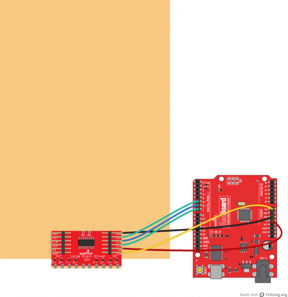
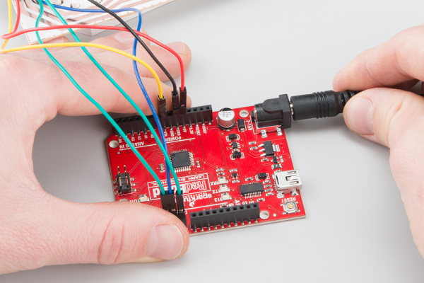
We will be using the Arduino’s regulated 5V and unregulated 12V (from the wall adapter) to power the 7-segment display and Large Digit Driver.
Connect the Large Digit Driver to the the following pins on the Arduino.
| Large Digit Driver | Arduino |
|---|---|
| GND | GND |
| LAT | 5 |
| CLK | 6 |
| SER | 7 |
| 5V | 5V |
| 12V | VIN |
Example: One Large Digit
Load the Single Digit Example Code
Plug your Arduino into your computer via USB cable. Open up the Arduino program and copy in the following sketch.
Run
Upload the sketch to your Arduino, and plug the 12V adapter into the Arduino.
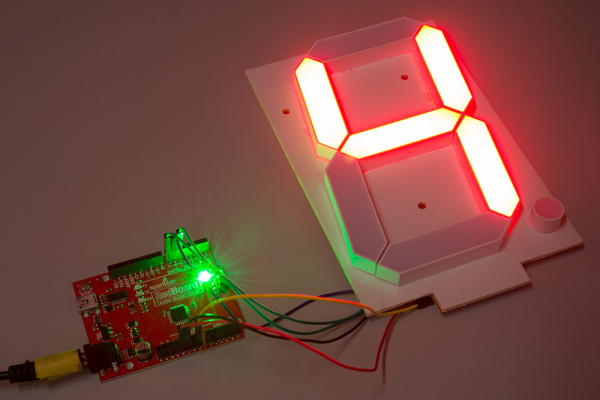
Flip the 7-segment display over. You should see it count the digits 0-9 (the decimal point will appear on 9).
Example: Two Large Digits
Attach a Second Digit
Use the 6-pin jumper wire to attach a second 7-segment display to the first display unit. Make sure that you connect GND of the OUT on the first display to the GND of the IN on the second display, LAT of the OUT on the first display to the LAT of the IN on the second display, and so on.
You will want to connect the Large Digit Driver on the right to the Arduino as per the Hardware Hookup section.
Load the Two Digit Example Code
Make sure the Arduino is plugged into your computer using a USB cable. Copy the following sketch into the Arduino program.
Run
Upload the sketch to your Arduino, and plug in the 12V supply. The 7-segment display (now two digits!) should count from 00 to 99.
Resources and Going Further
Now that we have tested the large 7-segment displays, they are ready to be used in your project! Feel free to change the code to display other numbers or symbols on the displays.
Resources
Here are some additional resource to help you with the Large Digit Driver:
- Large 7-Segment Display Datasheet
- Datasheet for the shift register on the Large Digit Driver
- Large Digit Driver GitHub Repository
Other Tutorials
What will you make with the Large Digit Driver? If you need some inspiration, check out these related tutorials:
Dungeons and Dragons Dice Gauntlet
Galileo Unread Email Counter
Interactive Hanging LED Array
Alphanumeric GPS Wall Clock
learn.sparkfun.com |CC BY-SA 3.0 | SparkFun Electronics | Niwot, Colorado
