SparkFun Blocks for Intel® Edison - Pi Block a learn.sparkfun.com tutorial
Available online at: http://sfe.io/t412
Introduction
The Pi Block breaks out and level shifts several GPIO pins from the Intel Edison. It presents them in the same configuration as a Raspberry Pi Model B.

Pi Block
Suggested Reading
If you are unfamiliar with Blocks, take a look at the General Guide to Sparkfun Blocks for Intel Edison.
Other tutorials that may help you on your Edison adventure include:
Board Overview

Pi Block Functional Diagram
USB Power - used to provide 5V to Pi Block and power the Edison. Note that the data lines are not connected to the Edison.
Power Button - The power switch is connected to the “PWRBTN” line on the Edison. This give the user the ability to place an Edison in sleep or power down the module completely. This does not affect power to other Blocks in the stack.
Power LED - The power LED illuminates when power is present on VSYS. This can come from the onboard USB Power or any other powered Block in the stack.
Expansion Header - The 70-pin Expansion header breaks out the functionality of the Intel Edison. This header also passes signals and power throughout the stack. These function much like an Arduino Shield.
LED Jumper - If power consumption is an issue, cut this jumper to disable the power LED.
VSYS Jumper - By default, a USB cable must be attached to the USB Power port to provide power to the 5V pins on the RPi B Header. You can power the Edison and Pi Block from another Block (e.g. Base Block), but there will not be 5V on the pins labeled “5V”. By closing this jumper, you can power the Edison and Pi Block from another Block, and ~4.2V (VSYS) will appear on the pins labeled “5V”.
RPi B Header - Same configuration as the old Raspberry Pi Model B pinout.
Using the Pi Block
To use the Pi Block, attach an Intel® Edison to the back of the board, or add it to your current stack. Blocks can be stacked without hardware, but it leaves the expansion connectors unprotected from mechanical stress.

Edison installed on Pi Block
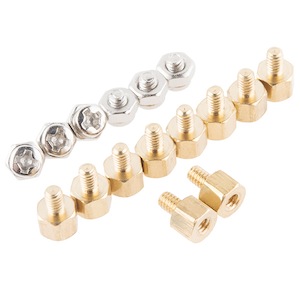
We have a nice Hardware Pack available that gives enough hardware to secure three blocks and an Edison.
You can put headers on the Edison side, which gives you easy access to the pin labels. Note that this pinout is mirrored from the Raspberry Pi Model B pinout.

Headers on Edison side
Alternatively, you can populate the back side of the Pi Block with headers. This method gives the same pinout as a Raspberry Pi Model B. You could, in theory, swap the Edison in for your Raspberry Pi on an existing project, or use Raspberry Pi accessories (e.g. Pi Wedge).

Or put headers on the back side of Pi Block
Using the Pi Block as an output device
If you want to use the Pi Block to control high power LEDs or relays, an external transistor or MOSFET will be required. It is possible to illuminate a small LED directly from the level shifter. It may not be as bright since the current output of the TXB0108 level converter is very low (~5ma).
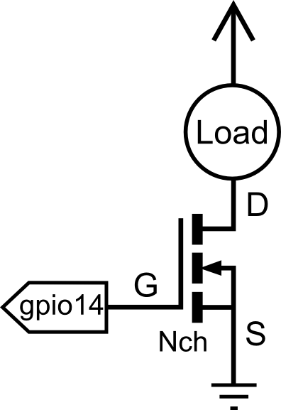
Connection Diagram for Load (LED, Motor, or Relay)
In the terminal, we will demonstrate how to activate and use a GPIO pin as an output.
First navigate to the GPIO directory on the Edison.
cd /sys/class/gpioSelect the GPIO pin to enable. In this case, we used GPIO 14, which is labeled “GP14” on the Pi Block.
echo 14 > exportNavigate to the newly created GPIO directory.
cd gpio14If you type “ls”, you should see a bunch of variables.
active_low  direction   power       uevent
device      edge        subsystem   value
Let’s set the “direction” of the port to output
echo out > directionTo confirm this, we will “cat” the value
cat directionYou should see the “out” in the command line. Now the device is configured as an output.“value” is where the status of the pin is set, 1 for high, 0 for low.
echo 1 > valueTesting with a multi-meter, small led, or oscilloscope, you should see a “high” status (3.3V) present on gpio14.
Using the GPIO Block as an input device
If you want the Pi Block to read switches, buttons, or other logic level inputs, you must pay attention to pull-up and pull-down resistors. The level converter on board is very weak. Here are two scenarios explained:
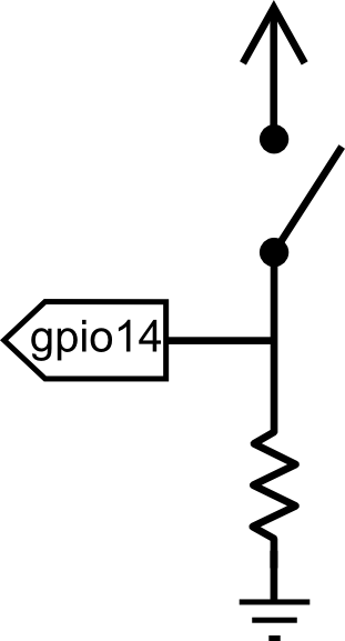
Connection Diagram for Active High Push Button
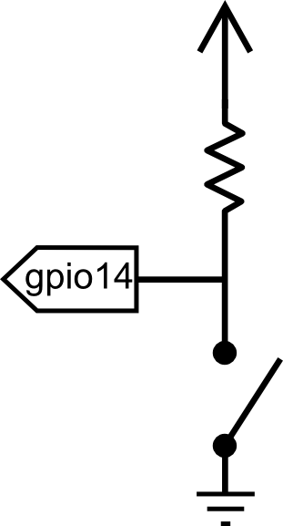
Connection Diagram for Active Low Push Button
In the terminal, we will demonstrate how to activate and use a GPIO pin as an input configured as an active high.
First, navigate to the GPIO directory on the Edison.
cd /sys/class/gpioSelect the GPIO pin to enable. In this case let us use GPIO 14.
echo 14 > exportNavigate to the newly created GPIO directory.
cd gpio14If you type “ls”, you should see a bunch of variables.
active_low  direction   power       uevent
device      edge        subsystem   value
Let’s set the “direction” of the port to output.
echo in > directionTo confirm this, we will “cat” the value.
cat directionYou should see the “in” in the command line. Now the device is configured as an input.“value” is where the status of the pin is set, 1 for high, 0 for low.
cat valueWith a button pressed, you should see a 1. When the button is not pressed you should see a 0. Using the up arrow, you can recall previously run commands.
C++ Examples
We’re assuming that you’re using the Eclipse IDE as detailed in our Beyond Arduino tutorial. If you aren’t, you’ll need to go to that tutorial to get up to speed.
Hardware Connection
Hardware support for this library is simple; one basic red LED and one momentary pushbutton. We’re using a 2N3904 NPN transistor to drive the LED, however, as the drive strength of the outputs on the Pi Block is quite weak. As you can see in the diagram, you’ll also need a couple of 1kΩ resistors and a single 330Ω resistor.

While we’ve used GPIO45 and GPIO46 in this example, this code can be used with any of the pins on the Pi breakout. The GPIO to MRAA pin map can be found in the Resources and Going Further section.
Code
Follow the instructions in the programming tutorial to create a new project named “SparkFun_Pi_Block_Example”. Once you’ve created the project, open the “SparkFun_Pi_Block_Example.cpp” file and replace all the existing code with the code block below.
language:c
  /****************************************************************
  Example file for SparkFun Pi Block Support

  14 Jul 2015- Mike Hord, SparkFun Electronics
  Code developed in Intel's Eclipse IOT-DK

  Modified on July 30, 2015 by Shawn Hymel, SparkFun Electronics

  This code requires the Intel mraa library to function; for more
  information see https://github.com/intel-iot-devkit/mraa

  This code is beerware; if you use it, please buy me (or any other
  SparkFun employee) a cold beverage next time you run into one of
  us at the local.
  ****************************************************************/

#include "mraa.hpp"

#include <iostream>
#include <unistd.h>

using namespace mraa;
using namespace std;

int main()
{

  // Oddly, GPIO pin assignment numbers when using the MRAA libraries are not
  //  the same as those inside the operating system. Thus, while we're using
  //  pin 46 as far as the OS is concerned to drive the LED, we're using pin 32
  //  as far as MRAA is concerned. The cheat sheet for that can be found here:
  //  https://github.com/intel-iot-devkit/mraa/blob/master/docs/edison.md
  Gpio LEDPin(45);
  LEDPin.dir(DIR_OUT);

  // Now do a quick little flicker.
  LEDPin.write(0);
  usleep(100000);
  LEDPin.write(1);
  usleep(100000);
  LEDPin.write(0);

  // Alternatively, we can declare the pin in "raw" mode, which has a slightly
  //  different and more unwieldy constructor.
  Gpio buttonPin(32, true, true);
  buttonPin.dir(DIR_IN);

  // In this infinite loop, we'll blink the LED once whenever someone presses
  //  the button.
  while (1)
  {
    // We *know* that if the IO pin reads as 0, or is low, read() returns zero.
    //  However, if it's high, it *may* return something else; the only guarantee
    //  is that it will be nonzero. Thus, don't test to see if a read() returned
    //  a 1!!!
    if (buttonPin.read() == 0)
    {
      LEDPin.write(1);
      sleep(1);
      LEDPin.write(0);
      sleep(1);
    }
  }

  return MRAA_SUCCESS;
}
Additional Examples
Because this block is just a GPIO access device, the existing MRAA GPIO examples can be used with it.

When you create a new project in the Eclipse IDE, it will offer you the option of several starter projects. Some of them, noted above, are good examples of using the MRAA GPIO functions. They’re more complex than what we’ve provided here, however.
For full documentation of the C++ API for GPIO pins, please visit the official MRAA documentation.
Resources and Going Further
Pin Map
You might have noticed that we used GP46 in hardware and GPIO 32 in our example code. This is because the MRAA library uses a different number for the pins. If you would like to use MRAA to control hardware, figure out which GPIO pins you plan to use on the table below (labeled “Edison Pin”) and then use the MRAA Number in software.
The available pins on the Pi Block have been highlighted in yellow in the table.
Notes:
- Input/output voltage on the Pi Block is 3.3V
- Input/output voltage on the GPIO Block is 3.3V by default
- Input/output voltage on the Arduino Breakout is 5V
- Input/output voltage on the Mini Breadboard is 1.8V
MRAA pin map table based on Intel’s IOT Dev Kit Repository
| Edison Pin (Linux) | Arduino Breakout | Mini Breakout | MRAA Number | Pinmode0 | Pinmode1 | Pinmode2 |
|---|---|---|---|---|---|---|
| GP12 | 3 | J18-7 | 20 | GPIO-12 | PWM0 | |
| GP13 | 5 | J18-1 | 14 | GPIO-13 | PWM1 | |
| GP14 | A4 | J19-9 | 36 | GPIO-14 | ||
| GP15 | J20-7 | 48 | GPIO-15 | |||
| GP19 | J18-6 | 19 | GPIO-19 | I2C-1-SCL | ||
| GP20 | J17-8 | 7 | GPIO-20 | I2C-1-SDA | ||
| GP27 | J17-7 | 6 | GPIO-27 | I2C-6-SCL | ||
| GP28 | J17-9 | 8 | GPIO-28 | I2C-6-SDA | ||
| GP40 | 13 | J19-10 | 37 | GPIO-40 | SSP2_CLK | |
| GP41 | 10 | J20-10 | 51 | GPIO-41 | SSP2_FS | |
| GP42 | 12 | J20-9 | 50 | GPIO-42 | SSP2_RXD | |
| GP43 | 11 | J19-11 | 38 | GPIO-43 | SSP2_TXD | |
| GP44 | A0 | J19-4 | 31 | GPIO-44 | ||
| GP45 | A1 | J20-4 | 45 | GPIO-45 | ||
| GP46 | A2 | J19-5 | 32 | GPIO-46 | ||
| GP47 | A3 | J20-5 | 46 | GPIO-47 | ||
| GP48 | 7 | J19-6 | 33 | GPIO-48 | ||
| GP49 | 8 | J20-6 | 47 | GPIO-49 | ||
| GP77 | J19-12 | 39 | GPIO-77 | SD | ||
| GP78 | J20-11 | 52 | GPIO-78 | SD | ||
| GP79 | J20-12 | 53 | GPIO-79 | SD | ||
| GP80 | J20-13 | 54 | GPIO-80 | SD | ||
| GP81 | J20-14 | 55 | GPIO-81 | SD | ||
| GP82 | J19-13 | 40 | GPIO-82 | SD | ||
| GP83 | J19-14 | 41 | GPIO-83 | SD | ||
| GP84 | J20-8 | 49 | GPIO-84 | SD | ||
| GP109 | J17-11 | 10 | GPIO-109 | SPI-5-SCK | ||
| GP110 | J18-10 | 23 | GPIO-110 | SPI-5-CS0 | ||
| GP111 | J17-10 | 9 | GPIO-111 | SPI-5-CS1 | ||
| GP114 | J18-11 | 24 | GPIO-114 | SPI-5-MISO | ||
| GP115 | J17-12 | 11 | GPIO-115 | SPI-5-MOSI | ||
| GP128 | 2 | J17-14 | 13 | GPIO-128 | UART-1-CTS | |
| GP129 | 4 | J18-12 | 25 | GPIO-129 | UART-1-RTS | |
| GP130 | 0 | J18-13 | 26 | GPIO-130 | UART-1-RX | |
| GP131 | 1 | J19-8 | 35 | GPIO-131 | UART-1-TX | |
| GP134 | J20-3 | 44 | ||||
| GP135 | J17-5 | 4 | GPIO-135 | UART | ||
| GP165 | A5 | J18-2 | 15 | GPIO-165 | ||
| GP182 | 6 | J17-1 | 0 | GPIO-182 | PWM2 | |
| GP183 | 9 | J18-8 | 21 | GPIO-183 | PWM3 |
Edison General Topics:
- General Guide to Sparkfun Blocks for Intel Edison
- Edison Getting Started Guide - Programming with Arduino
- Loading Debian (Ubilinix) on the Edison
Block Specific Topics:
learn.sparkfun.com |CC BY-SA 3.0 | SparkFun Electronics | Niwot, Colorado