Capacitor Kit Identification Guide a learn.sparkfun.com tutorial
Available online at: http://sfe.io/t425
Introduction
You never know when you’ll need a capacitor. Sometimes you need a little more power supply decoupling, an output coupling cap, or careful tuning of a filter circuit – all applications where capacitors are critical. The SparkFun Capacitor Kit contains a wide range of capacitor values, so you will always have them on hand when you need them.

This tutorial will help you identify the contents of your kit, and show you a couple tricks to expand the range of values even further.
Suggested Reading
- If you want more general information about capacitors, you can start with our Capacitor Tutorial.
- Capacitor values are expressed using metric prefixes
- The electrolytic capacitors in this kit are polarized.
Kit Contents
The Capacitor Kit contains caps on decade intervals from 10 picofarads to 1000 microfarads.

| Capacitor Kit Contents | |||||
| Value | Type | Marking | Quantity | Voltage Rating | |
| 10pF | Ceramic | 100 | 10 | 50V | |
| 22pF | Ceramic | 220 | 10 | 50V | |
| 100pF | Ceramic | 101 | 10 | 50V | |
| 1nF | Ceramic | 102 | 10 | 50V | |
| 10nF | Ceramic | 103 | 10 | 50V | |
| 100nF | Ceramic | 104 | 25 | 50V | |
| 1 µF | Electrolytic | 1µF/50V | 10 | 50V | |
| 10 µF | Electrolytic | 10µF/25V | 10 | 25V | |
| 100 µF | Electrolytic | 100µF/25V | 10 | 25V | |
| 1000 µF | Electrolytic | 1000µF/25V | 10 | 25V | |
There are ten pieces of most values, but 25 pieces of 100 nanofarads, which are commonly used for local supply decoupling near ICs. There are also ten pieces of 22pf, which are frequently used as load capacitors when building crystal oscillators.
Capacitor Identification
Capacitor Marking Review
Let’s face it, a Farad is a lot of capacitance. Capacitor values are usually tiny – often in the millionths or billionths of a Farad. To express those small values succinctly, we use the metric system. The following prefixes are the modern convention*.
| Capacitor Metric Prefixes | |||
| Prefix | SI Notation | Fraction | Symbol |
| Microfarad | 10-6 | One Millionth | µf |
| Nanofarad | 10-9 | One Billionth | nf |
| Picofarad | 10-12 | One Trillionth | pf |
Mu (µ), the symbol for micro, can be an issue for typesetting. It's hard to type, and not every font has the symbol. At SparkFun, we often use the letter 'u' as a substitute. Sometimes the letter 'm' is used instead, resuiting in micro-Farads being abbreviated as 'mF.' Technically, there's also a "milli-Farad," but in practice, milli-Farads are almost never seen, with thousands of micro-Farads being much more common.
Time and geography have an influence as well. In olderNorth American designs, nano-Farads are uncommon, with BOMs and schematics instead using only µF and pF, padded with leading or trailing zeros. One example of this convention is Digikey'scapacitor search page.
The Ceramic Caps
The smaller values in the kit are 50V rated ceramic capacitors. These are small, nonpolarized caps with yellow blob for their body.

From Left to Right: 10 pF, 22 pF, 100 pF, 1 nF, 10 nF, 100 nF
The value is printed on each in a three-digit code. This code is similar to the color code on resistors, but uses digits instead of colors. The first two digits are the two most significant digits of the value, and the third digit is the exponent on the 10. The value is expressed in terms of pico-Farads.
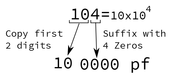
To decode the value, take the first two digits, then follow them with the number of zeros indicated by the third digit. 104 becomes “10” followed by “0000,” or 100000 pF, more succinctly written as 100 nF.
Electrolytic Caps
Electrolytic caps have larger, cylindrical bodies that look like small soda cans. They typically offer higher capacitance than ceramic caps. Unlike ceramics, they are polarized.

From Left to Right: 1µF, 10µF, 100µF, 1000µF
The markings on the ‘lytic caps are easily legible – the value and units are printed right on the body.
The value is followed with the voltage rating, indicating the maximum DC potential that the cap can withstand without damage. In this kit, the 1 µF is rated to 50V, the others are rated to 25V.
Polarized
The higher capacitance of electrolytics comes with a somewhat tedious detail – they are polarized. The positive leg needs to be kept at a higher DC potential than the negative leg. If they’re installed backwards, they’re prone to explode.
Thankfully, the leads are clearly marked.

There are two polarity indicators on an electrolytic cap:
- The stripe painted on the body usually denotes the negative lead.
- The positive lead is longer than the negative lead.
Clever Applications
Crystal Oscillators
The kit specifically includes 22 pF ceramic caps for building cyrstal oscillators, commonly required by microcontroller ICs.

The crystal oscillator circuit from the ProMicro
Value Combinations
This kit offers a wide array of values, but the decade-by-decade selection leaves some gaps in between. There are a couple of tricks that can be used to bridge those gaps, by combining caps in series or parallel.
Parallel
The values of capacitors wired in parallel are added together. You can gang up smaller caps to effectively form a larger cap.

Series
Capacitors wired in series combine in an inverse sum – take the reciprocal of each value, and add them together, then take the reciprocal of that sum.

Restated as a simplified guidelines while you’re at your workbench:
- If you want half the value of a cap in the kit, put two of that value in series.
- If you want double the value of a cap in the kit, put two in parallel.
Resources and Going Further
- Our Resistor Kit pairs nicely with the Capacitor Kit.
- If you want to measure capacitor values, you can build the Capacitance Meter Kit.
- Harry Bissell’s Cap FAQ is a very detailed guide to selecting capacitors.
- Our engineer Shawn gives a video demonstration of polarity and voltage ratings by Exploding Capacitors.
learn.sparkfun.com |CC BY-SA 3.0 | SparkFun Electronics | Niwot, Colorado