LilyPad Light Sensor Hookup Guide a learn.sparkfun.com tutorial
Available online at: http://sfe.io/t411
Introduction
The LilyPad Light Sensor is an e-textile friendly version of the Ambient Light Sensor Breakout. If you’ve used the breakout in a project before, the hookup and code will be very similar. You will need to connect to a LilyPad Arduino or other microcontroller to read the sensor values and use in your code.
This sensor outputs an analog value from 0 to 5V. In bright light (full daylight) this sensor will output 5V, and if completely covered will output 0V. In a typical indoor lighting situation, the sensor will output from around 1 to 2V.
To follow along with the code examples, we recommend:
Suggested Reading
To add this sensor to a project, you should be comfortable sewing with conductive thread and uploading code to your LilyPad Arduino. Here are some tutorials to review before working with this sensor:
- Light
- E-Textiles Basics
- Insulation Techniques for E-Textiles
- Short Circuits
- ProtoSnap LilyPad Development Simple Hookup Guide
Attaching to a LilyPad Arduino
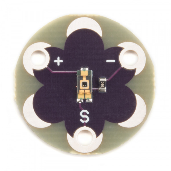
The LilyPad Light Sensor has three sew tabs - Power (+), Ground (-), and Signal (S). The signal tab should be connected to an analog tab on the LilyPad Arduino.
To follow along with the code examples in this tutorial, connect the light sensor to a LilyPad Arduino as shown below. Use alligator clips to temporarily connect Signal to A3 on a LilyPad Arduino, - to - on the LilyPad, and + to A5. If following along with a ProtoSnap - LilyPad Development Board, the sensor is pre-wired to A6. When you are finished prototyping, replace the alligator clips with conductive thread traces.
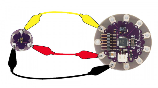
Connecting to a LilyPad Arduino Simple Board
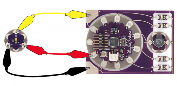
Attaching to a ProtoSnap - LilyPad Development Simple
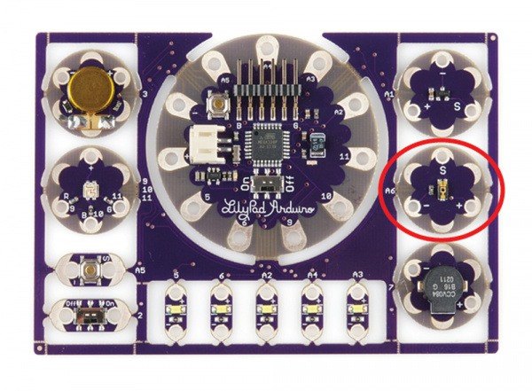
Using the pre-wired light sensor on the ProtoSnap - LilyPad Development Board
Reading Values in Serial Monitor
After connecting the light sensor, let’s take a look at the values it reads under different lighting conditions. For this we’ll use analogRead() and Serial.print().
Don't forget to select the Serial Port that your LilyPad is connected to.
If prototyping with a LilyPad Development Board, change sensorPin to A6.
After uploading the sketch, click connect on the Serial Monitor below (or open up the Serial Monitor window if programming in the Arduino IDE). Numbers should begin to stream by. Observe how the numbers change as the ambient light changes. Use your hand to cover the sensor or a flashlight to shine more light on it. Next we’ll be using these values to control behaviors in our code.
Using Values to Trigger Behaviors
Next, we’ll make some decisions in the code based on the light sensor’s readings. This example code creates a simple automatic night light that turns on an LED when it’s dark.
We’ll use the analogRead() function to get data from the light sensor and compare it to a variable we set for darkness level. When the readings from the light sensor fall below our threshold set for dark, it will turn on the LED.
You can hook up a LilyPad LED to pin 5 or use the built-in LED attached to pin 13.
If your light sensor isn’t triggering correctly, check the output of the Serial Monitor to see if there’s a better value for the dark variable than what is set in the example code.
Project Examples
Light Sensitive Hat
Let your geek shine with this hat that blinks when the lights go down.


Musical Bracelet
Combining the sensor with a LilyPad Buzzer can create interesting interactive projects, for example this wearable light-controlled musical instrument or Opto-Theremin. Control tones on the buzzer by covering the LilyPad Light Sensor.


Twinkling Prom Dress
This prom dress project featured in this video uses an initial threshold setting and light sensor to trigger some LilyPad Pixel Boards.
EL Wire Light-Up Dog Harness
This project uses the Ambient Light Sensor Breakout, but you could easily use the LilyPad Light Sensor in its place. Create a harness for your dog that lights up when it gets dark.
EL Wire Light-Up Dog Harness
October 30, 2015
Resources and Going Further
Here are some resources for planning a project with the light sensor:
learn.sparkfun.com |CC BY-SA 3.0 | SparkFun Electronics | Niwot, Colorado