SparkFun LED Array (8x7) Hookup Guide a learn.sparkfun.com tutorial
Available online at: http://sfe.io/t488
Introduction
The LED Array (8x7) is a set of 56 LEDs arranged in a nice 8x7 grid. It relies on Charlieplexing to control individual LEDs, which means less GPIO pins are used (as opposed to a traditional grid format). This guide will walk you through connecting the LED array and using some code examples to make those LEDs light up. We even wrote a library to help you display some simple graphics and scrolling text!
Required Materials
To follow along with this guide, you will need the following additional parts:
Suggested Reading
If any of these subjects sound unfamiliar, considering reading the following tutorials before continuing on.
- What is an Arduino?
- Installing the Arduino IDE
- Installing an Arduino Library
- How to Use a Breadboard
- How to Solder - Through-hole Soldering
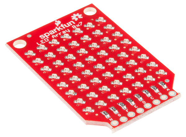
Board Overview
How Charlieplexing Works
To understand how the LED Array (8x7) works, we need to first learn a little about Charlieplexing. The name came from Charlie Allen at Maxim Integrated, who proposed the solution in 1995 for controlling multiple LEDs with less pins from a microcontroller.
The technique relies on using the ability for microcontroller pins to enter into a high impedance state (tri-state) and thus prevent current from entering or leaving that pin. Let’s take a 3-pin example. With Charlieplexing, we can have 6 LEDs attached to 3 pins: n x (n - 1) = 3 x (3 - 1) = 6.

We need to use the microcontroller’s ability to tri-state pins to make this work. If we make pin 1 an output and high, pin 2 output and low, and pin 3 high impedance (“Hi-Z”), then D1 will light up.

If we switch it and make pin 2 high and pin 1 low, then D3 will light up.

And if we make pin 3 high, pin 2 low, and pin 1 Hi-Z, D6 will light up.

This works because we can make the unused pins high impedance from the microcontroller. High impedance mode looks like an open circuit, so current does not flow into or out from the Hi-Z pins.
If we cycle through all 6 permutations quickly enough, we can trick our eyes into thinking that all the LEDs are on. If we leave selected LEDs off, we can create simple images with our LED array!

The LED Array 8x7

The 8x7 LED array takes our 6-LED example and expands it out to 56 LEDs and 8 pins. We can cycle through all 56 permutations of the pins to turn each LED on individually, and if we cycle fast enough, we can create simple images and text (at least according to our eyes).
Hardware Setup
The LED Array can be connected many ways so long as you have 8 pins available on your Arduino. For this example, we are going to use a RedBoard and pins 2-9. Solder 8 male header pins facing away from the LEDs:

Attach the LED Array to a breadboard and connect pins 2-9 on the RedBoard to pins A-H, respectively:

Note that you can also solder right-angle headers to the LED Array and RedStick or Pro Mini (again, pins A-H attached to pins 2-9) to achieve a seamless look:

Codebender Example
Now that we have the LED Array connected to our Arduino, we can run a simple test to make sure it is working. This example doesn’t require any additional libraries. Simply plug the shield into your Arduino, and upload the example code. Should you want to read how to install the libraries manually with Arduino, skip to the next section.
NOTE: For this example, we're hosting the code on codebender, which not only features code-sharing, but also allows anyone to upload and debug Arduino sketches from within a web browser. Plus, it works on lower-tech machines, like Chromebooks!
There are codebender plugins for Chrome, Chromium, and Firefox. Visit the codebender plugin page for help installing the codebender plugin.
If the codebender embeds don't work for you, we'll also provide a download link to the example code.
Plug your RedBoard, UNO, Pro Mini, RedStick, or other 168/328-based Arduino into an available USB port. Make sure the correct board and the associated COM port are selected in the Codebender box below. Click “Run on Arduino”.
Your LED Array should scroll “Hello World.”

Arduino Library
If the Codebender example did not work, you can also manually download the LED Array 8x7 Arduino library. To start, we’ll need the Chaplex library:
Additionally, we need the LED Array 8x7 Arduino library, which you can download as a ZIP file from GitHub or directly from this link:
Download the SparkFun LED Array 8x7 Arduino library
Once you have both libraries downloaded, follow this guide to install them in Arduino.
Open the Arduino IDE, and select File > Examples > SparkFun LED Array 8x7 > Demo. Select your Arduino and serial port, and upload the program.

You should see the LED array scroll through some example text and graphics.

Resources and Going Further
Here are a few resources you may find useful as you use your LED Array:
- SparkFun LED Array 8x7 Github Repo - PCB design files
- SparkFun LED Array 8x7 Arduino Library GitHub Repo - Library source code and example code
For some inspiration on how to use your LED Array, check out these tutorials:
BadgerHack: Sensor Add-On Kit
learn.sparkfun.com |CC BY-SA 3.0 | SparkFun Electronics | Niwot, Colorado