Serial Basic Hookup Guide a learn.sparkfun.com tutorial
Available online at: http://sfe.io/t597
Introduction
The Serial Basic is an easy to use USB to Serial adapter based on the CH340G IC from WCH. It works with 5V and 3.3V systems and should auto install on most operating systems without the need for additional drivers. It’s a great lower cost option to the extremely popular FTDI Basic.

The Serial Basic uses the CH340G IC to quickly and easily convert serial signals to USB. It works great with all of our products including the Arduino Pro Mini, our GPS modules, cellular modules, and many other devices that uses serial communication.
Suggested Reading
This is an easy board to get started with, but, if you are not sure how serial works or have not used a terminal program before, you may want to checkout the following tutorials.
Serial Communication
Serial Terminal Basics
Serial Basic Overview
The pinout of the Serial Basic mimics the common DTR/RX/TX/VCC/CTS/GND pinout found on hundreds of FTDI-to-USB derivatives.

| Pin Label | Input/Output | Description |
|---|---|---|
| DTR | Output | Data Terminal Ready, Active Low |
| RXI | Input | Serial Receive |
| TXO | Output | Serial Transmit |
| VCC | Supply Output | Power supply 3.3V or 5V |
| CTS | Input | Clear To Send, Active Low |
| GND | Supply Output | Ground (0V) supply |
Alignment Markers
These GRN and BLK indicators are there to help you align the board properly with products that use this same pinout.

The Serial Basic mates seamlessly with products that use the standard serial connection. If you see a board with the BLK and GRN labels, then you know it will be compatible with the Serial Basic.

See the GRN and BLK labels on this nRF52832 Breakout?
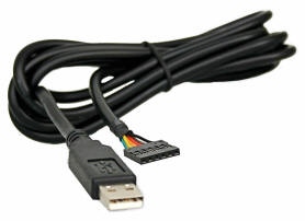
The cable with colored wires
Voltage Selection Jumper
There is a jumper on the rear of the board that controls the output voltage on the VCC pin. By default, the board outputs 3.3V and has 3.3V signals. Changing this jumper to 5V will cause the board to output 5V on the VCC pin with 5V signals.

Jumper is default to 3.3V VCC and I/O
When the jumper is set to 3.3V, the board uses an onboard 3.3V regulator capable of sourcing 600mA. If you attempt to pull more than 600mA, the regulator will go into short-circuit shutdown where it will only output 150mA.
When the jumper is set to 5V, the board will source as much power as your USB port will provide.
LEDs
There are two LEDs on the board connected to TX (Green) and RX (Yellow). This is a quick and handy way to see the serial traffic.

Hardware Test
To connect the board to a computer, you will need a standard A to micro-B USB cable. Plug the micro-B USB cable into a USB port on your computer and the other end into the Serial Basic. Your computer should automatically install the necessary drivers and create a COM port on your computer. If you are prompted for drivers, please see the Installing Drivers section.
The quickest and easiest way to make sure everything is working is to do a TX/RX loop-back. To do this, insert a jumper wire between TX and RX. Anything that is transmitted from the TX pin will be echoed back to the RX pin.

Open your favorite terminal program. Select the COM port that the Serial Basic is assigned to, and connect. When you type a character, you should see each character you type echoed back in the terminal.
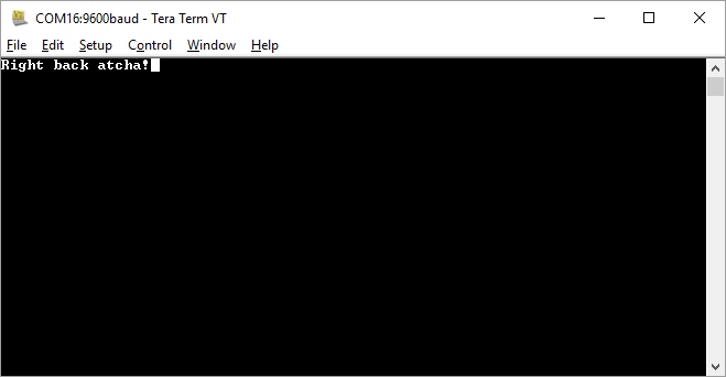
Success!
Which COM Port Do I Need?
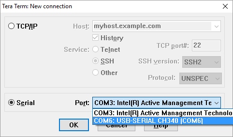
Most programs will show you a description of the USB device that created the port. Look for the port associated with CH340.
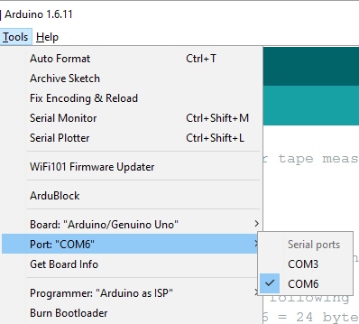
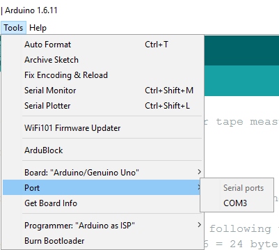
If you’re using the Arduino IDE, figuring out which COM port is the one you want is more difficult. Here’s the quick way to figure it out: attach the Serial Basic to your computer, and check which COM ports are listed. In the image below, we have two ports. Now close the Tool menu by clicking on the main Arduino IDE window.
Which COM port should I select?
Unplug the Serial Basic, and re-open the Tools->Ports submenu. You will see one of the serial ports is missing. That’s the one you want! Plug your Serial Basic back in, and use that COM port.
Drivers If You Need Them
The Serial Basic has been tested on Windows 7, Windows 8.x, Windows 10, Linux Mint, and OSX Yosemite, El Capitan, and Sierra. These operating systems have the CDC drivers pre-installed, which means you shouldn’t need to install any extra software. However, there are a wide range of operating systems out there, so, if you run into driver problems, you can get drivers here.
- Windows : Driver version 3.4 (2016-09-27)
- Linux : Driver v1.4 (2015-09-12)
- Mac : Driver v1.3 (2016-09-27)
The CH340G is made by WCH. You can find the latest version of their drivers here, but most of their pages are in Mandarin.
Resources and Going Further
Once you’ve got serial communication working, you’re ready to start playing with serial projects. Consider connecting to a GPS module like the LS20031 (one of my favorites) and watching the serial strings roll by. Or, you can use the Serial Basic to program and debug devices like the Arduino Pro Mini. There are tons of devices that use serial to communicate, so go explore!

The Serial Basic programming an Arduino Pro Mini
Check out these other resources for the Serial Basic.
- Schematic
- Eagle Files
- Hookup Guide
- Datasheet (CH340G)
- Drivers
- GitHub
Check out these other great SparkFun tutorials.
Serial Terminal Basics
RFM69HCW Hookup Guide
SparkFun USB to serial UART Boards Hookup Guide
SparkFun USB UART Breakout (CY7C65213) Hookup Guide
learn.sparkfun.com |CC BY-SA 3.0 | SparkFun Electronics | Niwot, Colorado