micro:bot Kit Experiment Guide a learn.sparkfun.com tutorial
Available online at: http://sfe.io/t644
Introducing the micro:bot Kit
The micro:bit is a great platform for learning how to build and program robots! Combining the micro:bit with the SparkFun moto:bit carrier board creates a flexible, low-cost robotics platform for anyone from students getting started with the micro:bit to the engineer looking to quickly prototype or build a proof of concept.
The micro:bot kit is the extension of that idea: build simple robots quickly that leverage the capabilities of the micro:bit while implementing peripheral sensors and motor functions with simple programming in the Microsoft MakeCode environment as a gateway into robotics.
What’s Included in the Kit?

The kit includes the following parts:
- 1x SparkFun moto:bit - Carrier board multiple I/O pins capable of hooking up servos, sensors and other circuits.
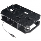
- 1x Shadow Chassis - Our go to robotics chassis for tabletop robotics.
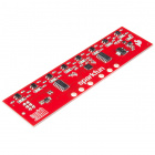
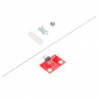
- 3x SparkFun Line Following Sensor - Three sensors for detecting lines and nearby objects.
- 2x Hobby Servo Motors - Program position with these motors.
- 2x Wheel — 65mm (Rubber Tire, Pair) - Wheels to attach to the Hobby Motors.
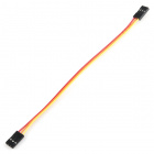
- 3x Jumper Wire — 3-pin, 6" - Wires to connect the line sensors to the moto:bit.
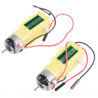
- 2x Hobby Gearmotor - Motors for driving the robots wheels.
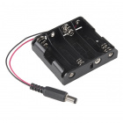
- 1x 4xAA Battery Holder - Battery pack for powering the micro:bit and the motors.

How to Use This Guide?
This guide is designed to get you started with the moto:bit board and the SparkFun micro:bot kit in a straight forward and simple way. We demonstrate each component’s functionality and the corresponding code to make it work.
While you explore this guide, we urge you to take your time and tinker with the sensors, code, and the ideas shared to build something tailored to your application and creativity. Our goal is to get you enough information and know-how to make you dangerous and then release you into the wild to do whatever you do with your robot.
Be sure to share your projects with us over Twitter or Facebook! We are excited to see you Start Something!
Suggested Reading
Before continuing with this guide, we recommend you be somewhat familiar with the concepts in the following tutorials:
Assembly Guide for RedBot with Shadow Chassis
Hobby Servo Tutorial
Getting Started with the micro:bit
Open Source
All of our experiments and guides are licensed under the Creative Commons Attribution Share-Alike 4.0 Unported License. Feel free to remix and reuse our work. But please, share the love and give us attribution for our hard work!
To view a copy of this license visit this link, or write: Creative Commons, 171 Second Street, Suite 300, San Francisco, CA 94105, USA.
About the moto:bit Board
The moto:bit is a carrier board for the micro:bit. Similar to an Arudino shield, it is designed to add functionality to the micro:bit without the hassle of a number of other boards, soldering, and all of those jumper wires.

In this case, the moto:bit takes a micro:bit and turns it into a full blown robotics platform. Wondering what you can do with it? Well here are a few things…
- Control motors through an onboard H-Bridge
- Read digital sensors such as line and bump sensors
- Read analog sensors like light sensors, temperature sensors, etc
- Control servo motors
- I2C port for extending functionality
That is a lot of options in terms of bells and whistles! Let’s take a closer look at the board and go over each section.
Edge Connector
The moto:bit connects to the micro:bit via an edge pin connector. This makes it handy to swap out micro:bits for programming, and it creates reliable connections to all of the different pins on the micro:bit.

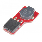
H-Bridge and Motor Pins
An H-Bridge is a chip that is the heart of a robot when it comes to driving motors and more specifically driving motors in both directions. Depending on the electrical state of specific pins on the H-Bridge, a motor drives forwards, backwards, and at different speeds. The good thing about this board is that if you are using Microsoft MakeCode, you actually don’t really need to know a whole lot about the H-Bridge itself.

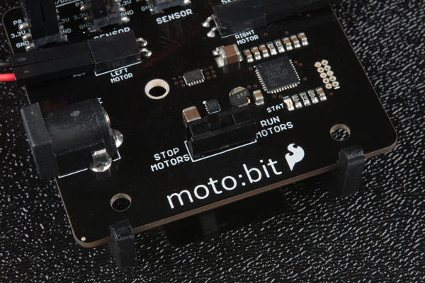
To connect the hobby motors that are included in the kit, you can insert them into the 2-pin female connectors just above the motor pins. The connectors are highlighted in the image below. Keep in mind that direction the hobby motors will move depends on the code to control the H-bridge motor driver, how the motors are attached to a chassis, and the way the motors are wired to the input pins.

Motor Control Switch
The moto:bit has a switch that controls the power supply to the motors. That way you can have the robot powered while working on it or programming it and know that the robot is not going to start moving and drive off of the table. Believe us… that happens all the time!

Input and Output Pins
The male pins on the moto:bit are for hooking up various inputs and outputs on your robot without using a breadboard to build elaborate circuits.

We have a number of sensors and actuators that are built in this pin formation and will work with this board.


Servo Ports
No robot is complete without an arm, a swiveling “head,” or some other type of movement other than wheels. Notice that a couple of the pin groups are designated as “Servo”. You can connect servo motors directly to these pins and use them right out of the box with Microsoft MakeCode.

I2C Port
We broke out the I2C port of the micro:bit to an external port so that you can add any I2C capable sensor or actuator you can think of. It is standard pin arrangement to many of our I2C sensor breakout boards.

Power
A standard barrel jack connector is used for easily powering your robot. We find that a 4xAA battery pack works great, but it will accept between 3 and 17 volts at the barrel jack. That’s a whole lot of robo-power!

Assembling Your Robot
This section will cover how to assemble your robot chassis.Assembly time: 30-60 minutes
The robot chassis requires the following pieces to build. You’ll find most of them in your SparkFun micro:bot kit.

Click on the image for a closer look.
| Letter | Part | Qty |
|---|---|---|
| A | Bottom Chassis Plate | 1 |
| B | Top Chassis Plate | 1 |
| C | Front Motor Mount | 2 |
| D | Rear Motor Mount | 2 |
| E | Side Strut | 4 |
| F | Encoder Mount (Not Used in this Guide) | 2 |
| G | moto:bit Mount | 2 |
| H | Battery Pack Clip | 1 |
| I | Line Follower Mount | 1 |
| J | Line Follower Mount Plate | 1 |
| K | Jumper Wire — 3-pin, 6" | 3 |
| L | Wheels | 2 |
| M | Nub Caster | 1 |
| N | DC Motors | 2 |
| O | Line Follower Boards | 3 |
| P | 4xAA Battery Holder | 1 |
| Q | 4xAA Batteries (Not Included) | 3 |
| micro:bit | Not Included in Kit | 1 |
| moto:bit | Included in Kit | 1 |
No Tools Necessary
The robot chassis does not require any additional tools.

A Note About Orientation
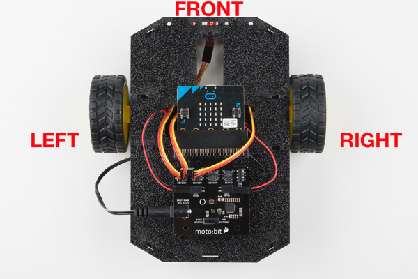
When we talk about the “front,” “left,” “right,” and “back” of the Shadow Chassis, we are referring to specific sides of the robot when viewed from above.
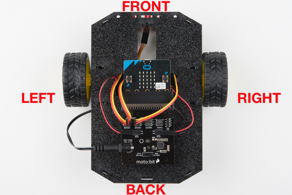
Notice that we consider the SparkFun moto:bit to be on the “back” of the bot and the Bumper Whiskers and Line Follower Boards to be in the “front.”
Assembly
Installing Motors
Let’s begin by installing the motors that will control the wheels. Locate the following:

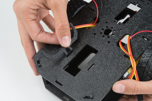
Attach Rear Motor Mounts
Hold the wires near the middle of the Motor (N), and carefully slide a Rear Motor Mount (D) in from the side and over the two motor wires. Be careful not to snag the wires, the cable tie, or the clear plastic strap.

Holding the motor wires, gently twist the Rear Motor Mount counter clockwise so that it snaps in place on the motor and the wires are centered in the gap of the motor mount. Again, be sure not to snag the wires under the motor mount.

Repeat the process for the second motor, ensuring that it is a mirror image of the first.

Attach the Front Motor Mounts
Slide a Front Motor Mount (C) onto the protruding eyelet on the front of a Motor (N). Ensure the rounded sides of the motor mounts are facing the same way.

Repeat the process for the second motor.

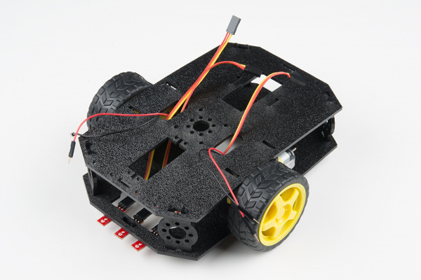
Attach the Motor Assemblies to the Chassis
Snap one of the motor assemblies into the left two horizontal slots of the Bottom Chassis Plate (A). Make sure that the rounded edges of the motor mounts and the wires are facing toward the center of the chassis. Repeat for the opposite motor.

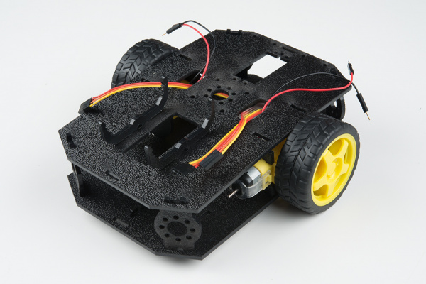
Attach the Wheels
Slide one Wheel (L) onto the plastic shaft of a Motor (N). Look at the motor shaft. Notice it has two flat edges. Make sure to line up the flat edges of the motor shaft with the flat edges of the wheel.

Repeat with the other wheel.

Installing the Line Sensors
This section will cover the Line Following Sensors array assembly. You’ll first build the Line Following array and then attach it to the chassis. Locate the following:

Construct the Line Follower Assembly
Attach the three Line Follower Boards (O) to the Line Follower Mount (I) such that the rectangular pegs in the Line Follower Mount poke through the mounting holes in the Line Follower Boards. Make sure the sensors are facing away/down from the clip of the mount.

Place the Line Follower Mount Plate (J) on top of the Line Follower Mount (I) so that the center clip of the mount is poking through the center slot of the plate.

Attach the Cables
You will need to connect a 3-Wire Jumper Cable (K) to each of the Line Follower Boards (O). Note the color of the wire attached to each pin.
Line Follower Connections:
| Jumper Wire Color | RedBot Sensor - Line Follower |
|---|---|
| Red | GND |
| Orange | VCC |
| Yellow | OUT |
Attach all 3 cables to the 3 Line Follower Boards. Notice that the yellow wire should be on the right (out) and the red wire should be on the left (ground).

Attach the Line Follower Assembly to the Chassis
Locate the wide, rectangular slot near the front of the chassis and snap the line follower assembly in from the bottom side of the chassis. Route the cables through the large hole in the bottom plate.

The bottom of your chassis should look like the following image allowing the line sensors to be facing down.

Final Assembly
With the motors and a few sensors attached, we can assemble the main body of the robot. Locate the following:

You will also need the Top Chassis Plate and Bottom Chassis Plate assemblies, which have any additional parts and sensors you attached in previous steps.
Attach the Nub Caster
Snap the Nub Caster (M) into the slot on the back of the Bottom Chassis Plate assembly. Make sure the Nub Caster is on the side opposite the motors (the bottom side).

Add the Side Struts
Snap the four Side Struts (E) into the diagonal slots on the four corners of the Bottom Chassis Plate assembly.

Pull the cables through the cutouts on the chassis.

Route the Cables
Position the Top Chassis Plate over the Bottom Chassis Plate – but do not snap the two plates together yet. Make sure that the front sides of each plate line up.
Route the wires and cables through the left and right oval slots in the Top Chassis Plate assembly as shown. For the center line follower sensor, route this cable through the right oval slot. Note that SIK-only cables are listed with an asterisk (*).
Cable Routing:
| Cable Connection | Oval Side |
|---|---|
| Left Line Follower | Center |
| Center Line Follower | Center |
| Right Line Follower | Center |
| Left Motor wires (red and black) | Left |
| Right Motor wires (red and black) | Right |

Attach Top Chassis Plate Assembly
Line up the Top Chassis Plate on top of all the struts, and carefully snap the Top Chassis Plate assembly onto the side struts and motor mounts. Press gently above each side strut individually until they each snap into place. If you have the Bumpers installed, make sure the boards are between the top and bottom plates.
If you need to remove the plate to change anything, gently pull upward on each side strut individually. Do not attempt to use pliers or hand tools, or you may end up snapping the plastic clip.
Attaching the moto:bit
In this section, you will add brains of the robot: the SparkFun moto:bit. Locate the following:

You will also need the full chassis assembly, which contains any additional parts and sensors you attached in previous steps.
Attach the moto:bit Mounts
Snap the two moto:bit mounts (G) into the vertical slots in the back of the top chassis plate near the large rectangular opening.
Both of these mounts will enable your moto:bit board to be mounted to the chassis.
Add the moto:bit
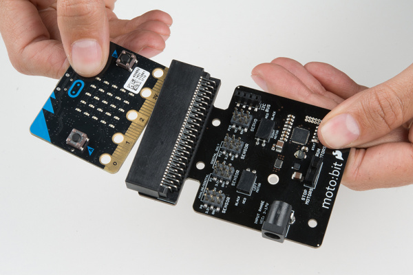
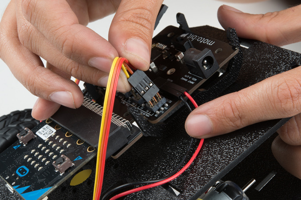
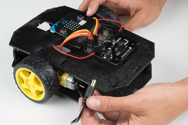
Before you snap in the moto:bit board, insert your micro:bit into the moto:bit as shown here.
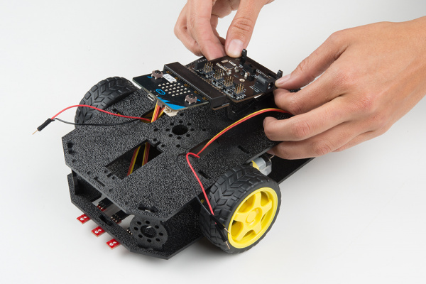
The moto:bit snaps into the lowest of the notches on the moto:bit Mounts (G). Make sure the power jack is facing the left side of the robot. Push gently and evenly until it snaps into place.
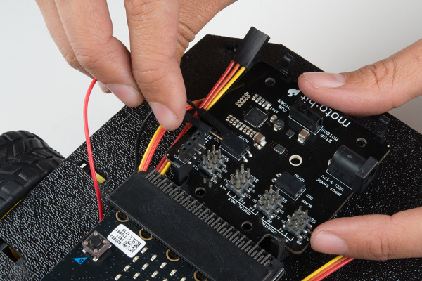
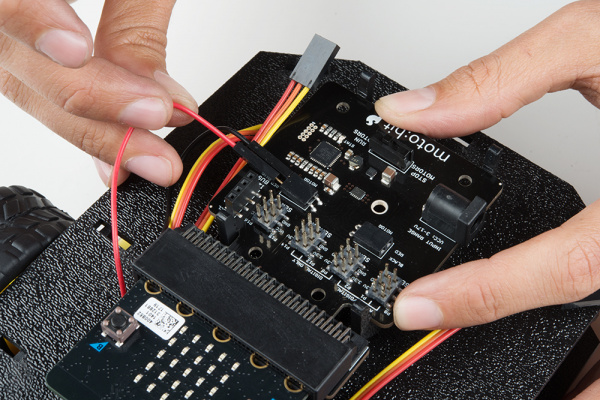
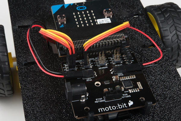
Connecting the Cables
It is time to connect the jumper wires; it is really important that these connections are right.
You can follow along with the pin out tables or scroll down for a diagram. Trace each cable poking through the top chassis plate to make sure you know what it is connected to.
Line Followers
Left Line Follower:
| SparkFun moto:bit Pins | Jumper Wires | Left Line Follower Board |
|---|---|---|
| P0 | 3-Wire Jumper Cable - Yellow | OUT |
| 3.3V | 3-Wire Jumper Cable - Orange | VCC |
| GND | 3-Wire Jumper Cable - Red | GND |
Center Line Follower:
| SparkFun moto:bit Pins | Jumper Wires | Middle Line Follower Board |
|---|---|---|
| P1 | 3-Wire Jumper Cable - Yellow | OUT |
| 3.3V | 3-Wire Jumper Cable - Orange | VCC |
| GND | 3-Wire Jumper Cable - Red | GND |
Right Line Follower:
| SparkFun moto:bit Pins | Jumper Wires | Right Line Follower Board |
|---|---|---|
| P2 | 3-Wire Jumper Cable - Yellow | OUT |
| 3.3V | 3-Wire Jumper Cable - Orange | VCC |
| GND | 3-Wire Jumper Cable - Red | GND |
Motors
Left Motor:
| SparkFun moto:bit Pins | Left Motor Jumper Wires |
|---|---|
| LEFT MOTOR - RED | Soldered on Motor Jumper Wire - RED |
| LEFT MOTOR - BLACK | Soldered on Motor Jumper Wire - BLACK |
Right Motor:
| moto:bit Pins | Right Motor Jumper Wires |
|---|---|
| RIGHT MOTOR - RED | Soldered on Motor Jumper Wire - BLACK |
| RIGHT MOTOR - BLACK | Soldered on Motor Jumper Wire - RED |
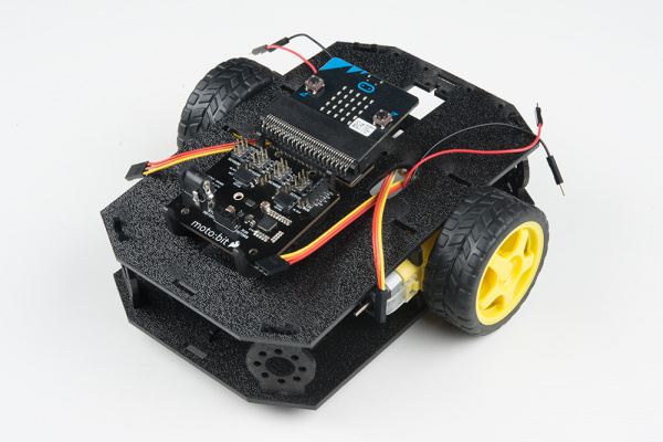
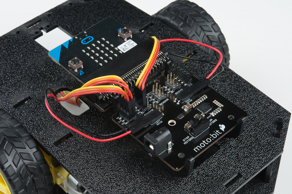
Once all wires are connected it should look like the following image.
Batteries
The last step is to provide a power source for the micro:bot. You will need to provide your own AA batteries (Q). Locate the following:

Insert Batteries
Insert the AA batteries into the Battery Holder (P). Makes sure the batteries are facing the correct direction, as per the markings inside of the Battery Holder.

Attach Battery Pack
Insert the Battery Holder (P) with batteries into the back cavity of the chassis. Position the Battery Holder so that the barrel jack cable comes out on the left side of the robot.
Insert the Battery Pack Clip (H) on top of the battery pack.
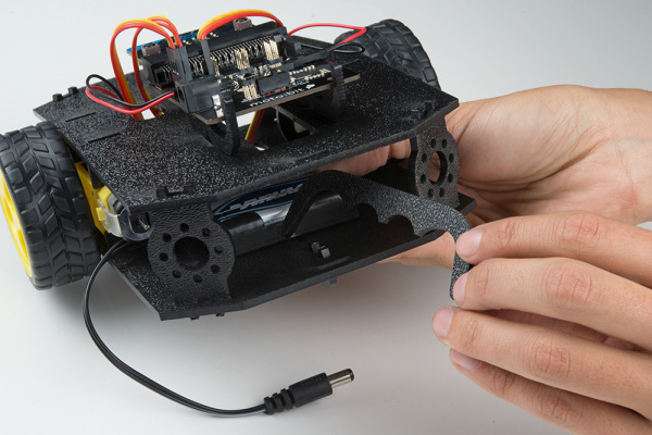
Twist and position the clip so that it rests on top of the battery pack.

Push the clip down into the vertical slots in the Bottom Chassis Plate so it snaps in place.

Route the barrel jack cable out of the left side of the chassis and up to the moto:bit.
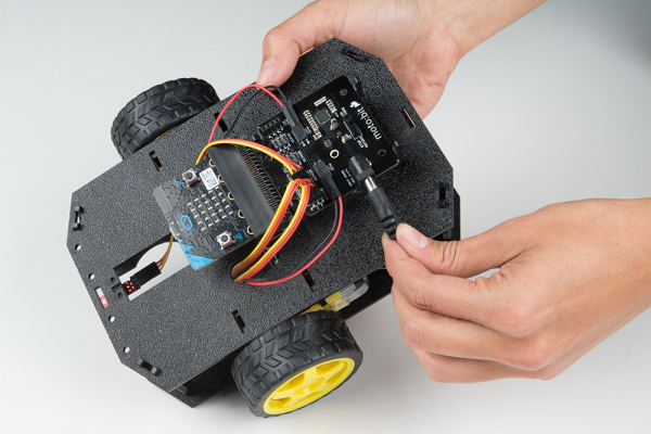
Plug the barrel jack cable into the barrel connector on the side of the moto:bit carrier board.
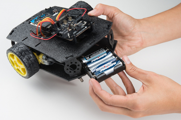
Changing the Batteries
If you find that you need to replace the batteries in the micro:bot, the process is simple. Unplug the battery pack from the moto:bit.
Turn the micro:bot over and push on the Battery Holder through the hole in the Bottom Chassis Plate. This will cause the Battery Pack Clip to unsnap from the Bottom Chassis Plate.

Slide the Battery Pack and Clip out from the back of the micro:bot.
Change the batteries, and follow the steps in Attach Battery Pack section above to put the Battery Pack back in the micro:bot.
Installing the moto:bit Package in MakeCode
To make the most out of the moto:bit with the least amount of coding, use the Microsoft MakeCode package we wrote for the moto:bit board.
Packages
If you have used Arduino before, you probably know about a thing called a library; which is a collection of code that extends the functionality of the core programming language. MakeCode packages work the same way.
There are some amazing differences between Arduino libraries and MakeCode packages. One of them is that MakeCode packages include JavaScript functions, which you can use when programming in text, as well as all of the blocks you need to program using the block method. This makes learning and using new packages straightforward and shortens the time to awesome when setting out to build the project of your dreams.
Installing a MakeCode Package
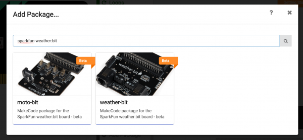
To install or add a new package to your MakeCode toolbox (the list of different block groups), click on “Advanced” and then on “Add Package.”

From here you can search for “SparkFun moto-bit,” and it should show up as a public package in the list. Go ahead and click on it.
This will add all of the blocks to your toolbox. In general, this is a bit tricky as, depending on how the package was written, it may either have its own toolbox or just add blocks to the existing ones. Take a look at your toolbox; for the moto:bit you should see…
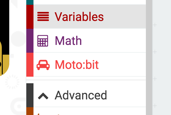
Great! You have now installed the moto:bit package and are ready to use the board as well as the components that come in the micro:bot kit. As a side note, for every new MakeCode project that you make, you will have to load packages over again. Not a big deal, but noteworthy! Now, let’s put your package to good use and get your robot moving!!!
Experiment 1: Driving and Turning
Introduction
The “Hello World” for the robotics world is getting your robot moving! Driving forwards, backwards and steering is goal #1 when you are dealing with wheeled / moving robots. This experiment will cover just that: getting your robot moving using our moto:bit software package for Microsoft MakeCode. Once you get through this first experiment you will be golden!
Parts Needed
- 1x micro:bit board (Not Included)
- 1x Micro B USB Cable (Not Included)
- 1x moto:bit carrier board
- 2x Wheels
- 1x Assembled shadow chassis
- 2x Hobby Gear Motors
- 1x 4xAA Battery Holder
- 4x AA Batteries (Not Included)
Didn’t get the kit? Have no fear! Here are the parts you will need to complete this experiment…


Suggested Reading
Getting Started with the micro:bit
Introduction to the Motors and Controlling Them

Motors take electrical energy and turn it into mechanical energy through putting a current through a coil of wire that creates a magnetic field. This then interacts with magnets in the motor, causing a push / pull effect. If you do that in a proper spacing and timing then you can spin a shaft.
These motors operate in a similar was as mentioned above, but they have a bit of help; a gear box. The ratio of the gearbox is 120:1, which means that for every 120 rotations of the motor shaft you get one rotation at the end of the gear box. This is a good thing because it gives our robot enough strength (torque) to turn wheels. In this case our gearbox also changes the axis of the shaft so that we can easily use them to drive our robot.
Hardware Hookup
You should have already hooked up the motors during the assembly process of putting the robot together. But, we have a couple of things that we would like you to double check!
First of all make sure that your red and black wires are plugged into your moto:bit and that they are in the correct ports. If you look closely the right and left ports are opposite from one another.

Why is that? Well, in robotics the right and left motors are mirrors of one another, which means they go in opposite directions from one another to go forward, hence the ports being backwards. If you plug them in as the same direction your robot would spin in a circle rather than drive forward! Weird, but true.
Running Your Script
We are going to use Microsoft MakeCode to program the micro:bit. Please open a browser window and navigate to makecode.microbit.org. This should open the MakeCode environment that you used to install the moto:bit package in.

Now, you can either download the following example script below and drag and drop it onto your micro:bit, or use it as an example and build it from scratch in MakeCode.
Code to Note
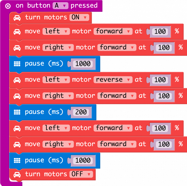
On Button Pressed
The On Button Press is an event function. Any code blocks that are placed inside of the block will only execute when that event happens. In this block when the A button is pressed on your micro:bit your robot will start moving. When it gets to the end of the program it will stop again until you press the A button again.
Turn Motors
The Turn Motors block gives you the ability to turn the motors ON or OFF in software. They are naturally OFF, so anytime you want to drive motors, you need to set them to ON. A good practice is to turn them OFF when your robot completes its task or should not be moving for long periods of time, this saves batteries and wasted power consumption.
Move Motors At
The Move Motors block is the basis of the moto:bit software package. You use this block by selecting which motor you want to control (RIGHT or LEFT), its direction (FORWARD or REVERSE) and the throttle / power percentage you would like the motor to spin at (0-100%). For your bot to move forward you need to have both motors drive in the same direction. To turn, or pivot, you set the motor directions in an opposite configuration.
Pause
The pause block is like a code stop sign. It tells the micro:bit to wait for a given amount of time in milliseconds. While it is waiting whatever you told before the pause will keep happening. So, if you want your robot to drive forward for 2 seconds, you set the robots motors to drive forward and then pause for 2000 milliseconds and then have the motors do something else, like stop.
What You Should See
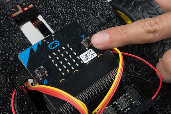
Once your script uploads to your micro:bit make sure the motors switch is changed from “STOP MOTORS” to “RUN MOTORS.” Press the A button on your micro:bit and your robot will drive forward for 1 second, pivot and the drive forward for another second then stop.

Troubleshooting
Robot not moving - Make sure your motors are hooked up correctly in the motor ports and your motor power switch is set to “run”, the battery pack is plugged in and you have fresh batteries
Moving in reverse?! - You can flip the wiring of your motor or use the
Set Motor Invertblock in yourOn Startblock to change what is forward vs. reverse.moto:bit package is not showing up - Try installing it again from the add package option in MakeCode
Experiment 2: Staying in a Box
Introduction
Robots are smart! They are smart because they use sensors to detect what the world around them and then respond to those conditions. One of the conditions our robot can respond to is the darkness of the surface that it is driving on. It can detect lines, a gradient of darkness or a blacked out area. In this experiment you will program your robot to stay inside of a box that you have drawn on a surface.
Parts Needed
- 1x micro:bit board (Not Included)
- 1x Micro B USB Cable (Not Included)
- 1x moto:bit carrier board
- 3x Line following Sensors
- 1x micro-B USB Cable
- 1x 4xAA Battery Holder
- 4x AA Batteries (Not Included)
Didn’t get the kit? Have no fear! Here are the parts you will need to complete this experiment…

Suggested Reading
Getting Started with the micro:bit
Introduction to the Line Sensors
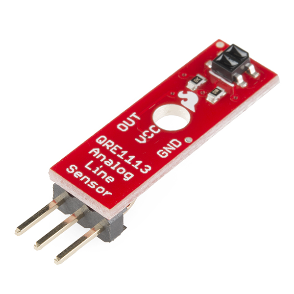
The Line Follower sensor is an add-on for your shadow chassis that gives your robot the ability to detect lines or nearby objects. The sensor works by detecting reflected light coming from its own infrared LED. By measuring the amount of reflected infrared light, it can detect transitions from light to dark (lines) or even objects directly in front of it.
The sensor has a 3-pin header which connects directly to the moto:bit carrier board via female to female jumper wires. A mounting hole lets you easily connect one or more of these to the front or back of your robot chassis.
Hardware Hookup
Like the motors, you should have already hooked up the line sensors during the assembly portion of this guide. You can go there now for the full assembly instructions. Double check to make sure that the wires are hooked up to your line sensors correctly!
The line sensors hookup to your moto:bit via female / female jumper wires that snake through the chassis of your robot up to the moto:bit. The sensors hookup to the moto:bit in the following order:
- LEFT =>
P0 - CENTER =>
P1 - RIGHT =>
P2
Double check to make sure they are hooked up correctly and in the proper orientation
Running Your Script
Be sure to add the moto:bit package as instructed in the Installing the moto:bit Package in MakeCode section of this tutorial.
Now, you can either download the following example script below and drag and drop it onto your micro:bit, or use it as an example and build it from scratch in MakeCode.
Code to Note
Creating a Variable
In Microsoft MakeCode you need to be able to create variables to store information for your robot to compare against, or to just remember. You can use the built in variables under the Variables drawer as shown below.

But, you can also make your own custom variables. To do this click on the Variables drawer and select Make New Variable. You can then name it and use it in your program.

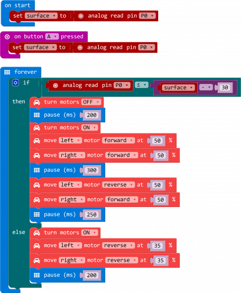
Set To
To store a value or piece of information in a variable you use the Set to block. This allows you to select a variable and set it to a value block of your choice. In this case the line sensor value on pin A0. We do this once in the On Start block to get a base reading from the sensor.
Analog Read Pin
To get that base reading from the line sensor we use the Analog Read Pin block to get an analog value (0 - 1023) from the line sensor. 0 is totally black and 1023 is totally saturated white. Your surface will be something probably in between.
If
To compare the current reading of the line sensor to its known baseline value that was captured and stored in the On Start block we use an if statement block. The if block accepts a logical statement. If that statement (Sensor Value < Surface - 30) is true then the if block runs then “then” section of code. If that statement is false then the “else” section of the block is run.
You may be asking yourself why subtract 30 from the surface value. Well, that number is a sensitivity value. The sensor reading fluctuates as the robot moves around, by subtracting 30 from the original surface variable we give the change in lighting a “wiggle room” of 30. If you want your sensor to be more sensitive you make the number smaller, if you need it less sensitive make it bigger.
What You Should See
Once your code is loaded find a light surface, preferably white and add a line of black tape to the surface and press the RESET button on your micro:bit. In fact, if you have a large enough space you can create a 3' square you will be perfect! Change the motor switch from “STOP MOTORS” to “RUN MOTORS.”

Your robot will drive forward until the black tape is directly under the center line sensors. When that happens your robot will stop, reverse, pivot a bit and try to drive forward again, hitting a line once more. If it works correctly your robot should stay inside of the box forever!
Troubleshooting
Moto:Bit blocks not showing up - Make sure you have a network connection and you have added the package to your makeCode environment.
Micro:Bit not showing up on my machine - Try unplugging the USB cable and plugging it back in. Also, be sure that you have the cable inserted all the way into your micro:bit
Robot doesn’t detect line - If changing the width of your line doesn’t help, remember line sensor calibration settings can be very sensitive depending on your environment.
Experiment 3: Following a Line
Introduction
OK, you have your robot staying inside of box drawn on the floor, but that still seems a little odd and random. You want your robot to go somewhere, do something and then keep going! In this experiment you will elaborate what you learned from Experiment 2 to get your robot to follow a line.
Parts Needed
- 1x micro:bit board (Not Included)
- 1x Micro B USB cable (Not Included)
- 1x moto:bit carrier board
- 1x Shadow Chassis
- 3x Line following sensors
- 3x Servo style jumper wires
- 1x micro-B USB Cable
- 1x 4xAA Battery Holder
- 4x AA Batteries (Not Included)
Didn’t get the kit? Have no fear! Here are the parts you will need to complete this experiment…
Suggested Reading
Getting Started with the micro:bit
Introduction to Using Multiple Line Sensors

In the previous experiment you used a single line sensor (the middle sensor) to detect the line on the floor. That is great for staying inside of a line, but now, you need to follow a line. That is where the other two line sensors come in.
Essentially, you want the center sensor to detect the line, but not the other two, meaning that the robot is centered on the line. If one of the side sensors detect a line it means that you are veering to one side or another and your robot should correct itself. We will use the information from multiple sensors combined with an if/else statement block to build a decision tree for your robot to follow.
Hardware Hookup
Like the motors, you should have already hooked up the line sensors during the assembly portion of this guide. You can go there now for the full assembly instructions. Double check to make sure that the wires are hooked up to your line sensors correctly!
The line sensors hookup to your moto:bit via female / female jumper wires that snake through the chassis of your robot up to the moto:bit. The sensors hookup to the moto:bit in the following order:
- LEFT =>
PO - CENTER =>
P1 - RIGHT =>
P2
Double check to make sure they are hooked up correctly and in the proper orientation
Running Your Script
Be sure to add the moto:bit package as instructed in the Installing the moto:bit Package in MakeCode section of this tutorial.
Now, you can either download the following example script below and drag and drop it onto your micro:bit, or use it as an example and build it from scratch in MakeCode.
Code to Note
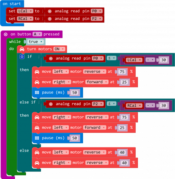
lCal / rCal
Like in the previous experiment, you need to set a baseline value for the surface that your robot is driving on. This is actually called a calibration value. Like the previous experiment, we need to do this, but for two sensors; right and left. We go through the same routine we did for the single sensor previously, but for the right and left sensors.
On Button Press
As in the first experiment we use the On Button Press block to start the program. This is so you can can get a good base reading and calibrate your sensors without having to wrestle with a robot that is trying to move around.
While
The While block is a logic block that is similar to the loop block, but a bit smarter. The While block accepts a TRUE/FALSE statement, if that statement is true the block will loop whatever code is placed inside of it. If that value is false the While block is simply skipped over. We hardcode a true value into the While block so that it constantly loops when the A button is pressed. That way we have the benefits of both the event block and the loop block without needing complicated programming.
What You Should See
Once you have loaded your script place your robot on a dark line on a light / white background. Make sure you have it centered with the line just underneath the center line sensor. Make sure the motor switch is changed from “STOP MOTORS” to “RUN MOTORS” and press the A button to start.
Your robot should drive forward until one of the side line sensors detects the line and then it will turn in that direction to correct itself. Depending on your line shape and thickness your robot may “waddle” more or less.
Troubleshooting
Robot drives in a circle - Double check your wiring and your code, your robot is not seeing the line. Also, double check that there isn’t something like dust blocking your sensor.
Robot isn’t moving - Pesky motor switch! Make sure that is set to “run” and you have fresh batteries
Robot waddles a lot! - Change the width of your line.
Robot doesn’t detect line - If changing the width of your line doesn’t help, remember line sensor calibration settings can be very sensitive depending on your environment.
Experiment 4: Using the Accelerometer
Introduction
Now, what happens when something bumps into your robot? It just stays there? No! It should move out of the way, or do something. Not a smart robot! In this experiment you will use the accelerometer on the micro:bit to trigger the robot to move and also speed up if it starts to go up hill.
Parts Needed
- 1x micro:bit board (Not Included)
- 1x Micro B USB cable (Not Included)
- 1x moto:bit carrier board
- 2x wheels
- 1x assembled shadow chassis
- 2x Hobby Gear Motors
- 1x 4xAA Battery Holder
- 4x AA Batteries (Not Included)
Didn’t get the kit? Have no fear! Here are the parts you will need to complete this experiment…
Suggested Reading
What is Electricity?
Getting Started with the micro:bit
Introduction to the Accelerometer

Like the magnetometer (compass), the accelerometer is on the micro:bit itself.
Accelerometers are devices that measure acceleration, which is the rate of change of the velocity of an object. They measure in meters per second squared (m/s2) or in G-forces (g). A single G-force for us here on planet Earth is equivalent to 9.8 m/s2, but this does vary slightly with elevation (and will be a different value on different planets due to variations in gravitational pull). Accelerometers are useful for sensing vibrations in systems or for orientation applications. Vibration is what we are looking for!
Hardware Hookup
You have had the hardware hooked up the whole time! It is on the micro:bit! Feel free to move on.
Running Your Script
Be sure to add the moto:bit package as instructed in the Installing the moto:bit Package in MakeCode section of this tutorial.
Now, you can either download the following example script below and drag and drop it onto your micro:bit, or use it as an example and build it from scratch in MakeCode.
Code to Note
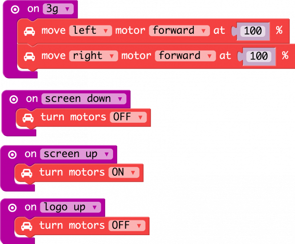
On [Acclerometer]
The micro:bit has a built in accelerometer that measures the gravitational forces that are acting upon it. With other microcontrollers this is sometimes hard to use and make sense of the data you receive from the sensor. But, MakeCode has simplified that for you in an event block under the Input drawer (you will see it as On Shake) that allows you to pick a number of different force levels, orientations and even patterns (like shaking it). We use this to detect a number of orientations that you can put your robot in. For example the motors will only be ON in the screen up orientation.
If you tap the robot hard enough it will run / drive away from you. If you flip it over the motors will turn off. Same thing holds true if you place it on its tail with the micro:bit pointing up.
Try playing around with the different events that you can trigger with the accelerometer. Can you get it to detect bumping into an object like the wall and have it respond???
What You Should See
Once your code is loaded to your micro:bit and your motor switch is set to “RUN MOTORS.” Your robot should not do anything at first. Give it a good tap / smack on top of the micro:bit. If you apply enough force to it your robot should run away. To stop your robot either flip the robot over to its back the motors should stop, or pick it up and set the robot on end with it sitting on its tail with the micro:bit logo pointing up. To run the program again, return the robot to its wheels right side up and smack it again.
Troubleshooting
- Robot Doesn’t Move - Double check to make sure you have uploaded the new code to your board. Also, make sure your motor switch is set to the “RUN MOTORS” position.
Experiment 5: Controlling a Servo - Battle Bot
Introduction
Your robot should do something more than just drive around! Maybe control a small robotic arm, a gripper or even a weapon (see the bonus experiment if this peaks your interest!) of some kind. In this experiment you will integrate servo motors with your robot to build a Battle Bot with Jousting Lances. This experiment combines all the elements you’ve learned so far in this tutorial.
Parts Needed
- 1x micro:bit board (Not Included)
- 1x moto:bit carrier board
- 2x wheels
- 1x assembled shadow chassis
- 2x Hobby Gear Motors
- 2x Hobby servos
- 1x 4xAA Battery Holder
- 4x AA Batteries (Not Included)
Didn’t get the kit? Have no fear! Here are the parts you will need to complete this experiment…

Craft Supplies
- 2x Skewers
- Hot Glue and Gun
- Optional: Electrical Tape
Suggested Reading
Hobby Servo Tutorial
Getting Started with the micro:bit
Introduction to the Servo Motor

Unlike the action of most motors that continuously rotate, a servo motor can rotate to and hold a specific angle until it is told to rotate to a different angle. You can control the angle of the servo by sending it a Pulse Width Modulation (PWM) pulse train (turning a pin on and off really fast at different intervals); the PWM signal is mapped to a specific angle from 0 to 180 degrees in the servo block in MakeCode.
Inside of the servo there is a gearbox connected to a motor that drives the shaft. There is also a potentiometer that gives feedback on the rotational position of the servo, which is then compared to the incoming PWM signal. The servo adjusts accordingly to match the two signals.
Hardware Hookup
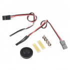
In this experiment you will actually be using two different servo motors to create a Battle Bot! One will be used as a “left” jousting lance and the other as the “right”. If you look at the servos, you will notice that they three wires have different colors; red, black and white. Red is the supply voltage, black is ground and white is the signal. Hook the two servos up to the moto:bit at the two labeled servo ports. Make sure you line up ground to ground.
The “right” servo is connected to pin P16 while the “left” is connected to pin P15. Using a bit of hot glue or tape, you can attach the servos to each side of the robot chassis.
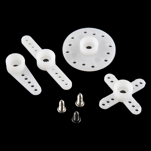
Next, you can build the jousting lances by utilizing some grilling skewers! You will only need two that can be cut down to the needed size. You can either glue or tape each skewer to the servo to the supplied attachments. Each servo set comes with a small bag of attachments as seen below. In this experiment, we utilized the double arm micro horn, but any of them will work.
Don’t have any skewers laying around? Be creative here!
Bot Assembled with Servos
This Battle Bot utilized electrical tape to mount the jousting lances to the servo motors, and it ended up looking something like this…

Now, set your contraption aside until you have uploaded your code.
Running Your Script
Be sure to add the moto:bit package as instructed in the Installing the moto:bit Package in MakeCode section of this tutorial.
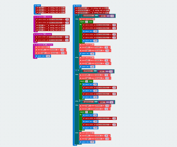
Now, you can either download the following example script below and drag and drop it onto your micro:bit, or use it as an example and build it from scratch in MakeCode.
Code to Note
Don’t be overwhelmed by everything this code has to offer! I know it looks rather menacing, but the truth is that you’ve already done all of this code in previous experiments.
Servo Write Pin to
The Servo Write Pin to block is found under the Pins drawer and it accepts a pin number that you have a servos signal wire attached to as well as an angle that you want it to rotate to. That’s the basics for controlling a servo motor with Microsoft MakeCode!
On Button A, On Button B and On Button A+B
In this example we use the On Button event blocks a lot. They allow us to break out different functions we want without messy if statements.
In this program the On Button A event block resets the calibration value for the table surface for the robot to use as a comparison value and also sets the servo positions to 90 degrees.
The On Button B block is used to set servo position to 45 degrees.
Finally the On Button A+B event block is used to run the program.
If / Then Statements
You may notice that there is a few if / then blocks inside of the if statement in the forever block. This will aid your Battle Bot in making decisions and knowing what it has to do next.
What You Should See
When your code is loaded onto your micro:bit the servo “arms” will move into a starting position and take initial readings for your line sensors to establish a comparison point to the ground environment.
Initially, the Battle Bot will move forward if none of the line sensors detect any kind of obstacle. If the center line sensor detects a direct collision the Battle Bot will immediately start both servos and move backwards. If the left or right line sensors detect an obstacle, the side that detected the obstacle will have the corresponding jousting lance start to move while turning away from it. So your Battle Bot is prepared to defend itself from any oncoming situation!
Troubleshooting
Servo moves in the wrong direction - Flip your servos, or change your code so that it rotates the correct direction.
Servo doesn’t move at all! - Double check your connections of the servos to the moto:bit to make sure that they are hooked up correctly.
Resources and Going Further
We produce a number of other kits and carrier boards that you can hook up to your micro:bit to help take your projects to the next level. Here is some further reading that may help you along in learning more about the world of electronics.
For more information on our micro:bit ecosystem, check out these tutorials:
SparkFun Inventor's Kit for micro:bit Experiment Guide
Getting Started with the micro:bit
micro:climate Kit Experiment Guide
learn.sparkfun.com |CC BY-SA 3.0 | SparkFun Electronics | Niwot, Colorado


