Qwiic HAT for Raspberry Pi Hookup Guide a learn.sparkfun.com tutorial
Available online at: http://sfe.io/t704
Introduction
This Qwiic HAT for Raspberry Pi is the quickest and easiest way to utilize SparkFun’s Qwiic ecosystem while still using that Raspberry Pi that you’ve come to know and love. This Qwiic HAT connects the I2C bus (GND, 3.3V, SDA, and SCL) on your Raspberry Pi to an array of Qwiic connectors. It also has a few important pins on the Raspberry Pi broken out for easy access. Since the Qwiic system allows for daisy chaining (as long as your devices are on different addresses), you can stack as many sensors as you’d like to create a tower of sensing power!

Required Materials
To follow along with this hookup guide, you will need any Raspberry Pi with 2x20 male headers.
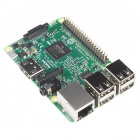
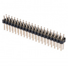
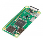
A Pi Zero W will also work but you will need to make sure to solder some male headers to it.
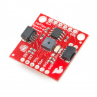
Now you probably didn’t buy the Qwiic HAT if you didn’t have any Qwiic products to use with it, right? If you don’t have any Qwiic products, the following might not be a bad place to start.


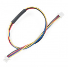
Finally, you’ll need our handy Qwiic cables to easily connect sensors to your Qwiic HAT. Below are a few options.


Required Setup Tools
As a desktop, these devices are required:
- USB Mouse
- USB Keyboard
- HDMI monitor/TV/adapted VGA
- 5V Power Supply
Suggested Reading
If you aren’t familiar with our new Qwiic system, we recommend reading here for an overview. We would also recommend taking a look at the following tutorials if you aren’t familiar with them.
Hardware Overview
The Qwiic HAT has 4 Qwiic connect ports, all on the same I2C bus. In addition to this, some of the pins on the Raspberry Pi are broken out for the user.

Hardware Assembly
To get started with your Qwiic HAT, simply plug it into the headers on the Raspberry Pi, make sure that the “USB” arrow on the HAT is pointing towards the USB on the Raspberry Pi.

Once the HAT is plugged in, you can start plugging in any Qwiic enabled sensors you might have.

I2C on Raspberry Pi
OS and Library Install
If you’re starting from scratch, with a blank microSD card, you’ll want to install Raspbian. If you’ve already got a working Raspbian system, skip ahead to step 3.
- Download the NOOBS image. As of this writing, it’s at version 2.4.4.
- Follow the official installation instructions.
- Follow the Wiring Pi Instructions to get git, update and upgrade your Rasbpian packages, then install WiringPi.
Be patient – each of these steps takes a while.
Once you’ve got wiringPi installed, run the gpio commands shown below.
>gpio -v>gpio readallIt should respond with some information about the wiringPi version and the Pi that its running on, then draw a table illustrating the configuration for the pins in the 40-pin connector.
Configuration
Like the SPI peripheral, I2C is not turned on by default. Again, we can use raspi-config to enable it.
- Run
sudo raspi-config. - Use the down arrow to select
5 Interfacing Options - Arrow down to
P5 I2C. - Select
yeswhen it asks you to enable I2C - Select
OKand thenFinish
Once you return to terminal, enter this command
>ls /dev/*i2c*The Pi should respond with
/dev/i2c-1Which represents the user-mode I2C interface.
Utilities
There is a set of command-line utility programs that can help get an I2C interface working. You can get them with the apt package manager.
sudo apt-get install -y i2c-toolsIn particular, the i2cdetect program will probe all the addresses on a bus, and report whether any devices are present. Call i2cdetect -y 1 to probe the first I2C bus, which is what the Qwiic HAT is connected to.
pi@raspberrypi:~/$ i2cdetect -y 1
     0  1  2  3  4  5  6  7  8  9  a  b  c  d  e  f
00:          -- -- -- -- -- -- -- -- -- -- -- -- --
10: -- -- -- -- -- -- -- -- -- -- -- -- -- -- -- --
20: -- -- -- -- -- -- -- -- -- -- -- -- -- -- -- --
30: -- -- -- -- -- -- -- -- -- -- -- -- -- -- -- --
40: -- -- -- -- -- -- -- -- -- -- -- -- -- -- -- --
50: -- -- -- -- -- -- -- -- -- -- -- -- -- -- -- --
60: 60 -- -- -- -- -- -- -- -- -- -- -- -- -- -- --
70: -- -- -- -- -- -- -- --
This map indicates that there is a peripheral at address 0x60. We can read and write its registers using the i2cget, i2cset and i2cdump commands.
Resources and Going Further
For more information, check out the resources below:
- Qwiic Hat Schematic (PDF)
- Qwiic HAT Eagle Files (ZIP)
- Qwiic System Landing Page
- Qwiic HAT GitHub Repository
Now that you have your Qwiic HAT ready to go, it’s time to check out some of SparkX’s Qwiic enabled products, many of which are on their way to becoming good old fashioned SparkFun products.


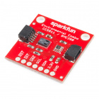
But I Already Have Sensors!
If you already have a handful of SparkFun sensors and parts? SparkFun has been putting our standard GND/VCC/SDA/SCL pinout on all our I2C boards for many years. This makes it possible to attach a Qwiic Adapter that will get your SparkFun I2C sensor or actuator onto the Qwiic system.
Here is the list of the boards that have the standard I2C pinout and will work with the Qwiic adapter board:
- 9DoF Stick IMU - LSM9DS1
- 9DoF IMU - MPU-9250
- 6DoF IMU - LSM303C
- 6DoF IMU - LSM6DS3
- Triple Axis Accelerometer - LIS3DH
- Triple Axis Magnetometer - MAG3110
- Triple Axis Magnetometer - MLX90393
- Compass Module - HMC6343
- Atmospheric Sensor - BME280
- Barometric Pressure Sensor - MS5803-14BA
- Barometric Pressure Sensor - T5403
- Humidity and Temperature Sensor - Si7021
- Digital Temperature Sensor - TMP102
- Particle Sensor - MAX30105
- Air Quality Sensor - CCS811
- ToF Range Finder - VL6180
- Haptic Motor Driver - DRV2605L
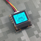
- Micro OLED Display
- RGB and Gesture Sensor - APDS-9960
- RGB Light Sensor - ISL29125
- LED Driver - LP55231
- DAC Breakout - MCP4725
- 16 Output I/O Expander - SX1509
- Battery Babysitter - BQ24075
Check out this related tutorial:
learn.sparkfun.com |CC BY-SA 3.0 | SparkFun Electronics | Niwot, Colorado