SparkFun SAMD21 Pro RF Hookup Guide a learn.sparkfun.com tutorial
Available online at: http://sfe.io/t810
Introduction
The SparkFun SAMD21 Pro RF is the fated meeting of a SAMD21 and a long-range RFM95W LoRa®-enabled radio. The outcome is a compact, blazing fast microcontroller with excellent point to point data transmission in the 915MHz ISM radio band with LoRa capabilities. In this tutorial we’ll break down the capabilities of the development board, give you a brief introduction to LoRa and get you familiarized with the two Arduino libraries that will get you started with the radio and LoRaWan. If you’re familiar with LoRaWan then skip ahead to the Hardware Overview, otherwise let’s get started with a brief introduction to LoRaWAN.

Required Materials
To follow along with this tutorial, you will need the following materials. You may not need everything though depending on what you have. Add it to your cart, read through the guide, and adjust the cart as necessary.


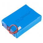
Single Cell LiPo Batteries
You can power the SAMD21 Pro RF with any of our stocked LiPo Batteries that is above 500mAh.


Tools
Depending on your setup, you may need a soldering iron, solder, and general soldering accessories.

Suggested Reading
If you’re not familiar with the following topics, or want a more in depth conversation related to the following, please follow the links below.
Installing Arduino IDE
SAMD21 Mini/Dev Breakout Hookup Guide
LoRaWAN with ProRF and The Things Network
Brief Introduction to LoRaWAN
LoRaWAN stands for Long Range Wide Area Network and describes the technology that allows for devices to send and upload data to the Internet using radio transmission. The technology is a frequency modulation scheme similar in theory but dissimilar to AM or FM which stand for Amplitude Modulation and Frequency Modulation respectively. You remember sine waves right? Amplitude modulation changes the height or amplitude of a wave when adding audio (or data) to it and frequency modulation would change, well, the frequency of a wave when adding audio (or data to it). The modulation scheme for LoRaWAN is more complex to explain but maintains this same theory of changing sine waves when they carry data; you can read more about it in detail below:
This scheme allows for data to be transmitted to the LoRa Network over a specific radio band known as the the Industrial, Scientific, and Medical Band (or ISM band for short). The frequencies of this specific radio band varies from country to country but as an example, the SAMD21 Pro RF will broadcast within the range of 902-928MHz in the Americas and in the range 863-870MHz in Europe. We reference the spectrum of broadcasting frequencies by its' center frequency, 915MHz in the Americas and 868MHz in Europe. Ok, we have a general idea that we broadcast in a band of frequencies using a technology that translates data into radio signals, but how do we get from the SAMD21 Pro RF to the “Internet of Things”?
Broadcasting and uploading requires three things: a Node, a Gateway or Concentrator, and a Network Server. The “Node” in this case is the SAMD21 Pro RF, which will broadcast its information into the void and hope that there is a Gateway or Concentrator nearby to hear it. A Gateway or Concentrator will take the information your node is broadcasting and push it to a Network Server like the The Things Network or Resin.io. Let’s read that in a different way, the Gateway or Concentrator takes the radio waves, demodulates them (i.e. translates them), and puts that information onto the Internet. Neat! Now it’s here on the Network Server that we get to interact with that data. For a more in depth explanation about LoRaWAN, check out this great tutorial.
LoRaWAN with ProRF and The Things Network
July 3, 2018
Want to setup your own Gateway? Check out the tutorial below!
ESP32 LoRa 1-CH Gateway, LoRaWAN, and the Things Network
August 14, 2018
Hardware Overview
If this is your first time with the SAMD21 then check out our great write up on the hardware specifications of the SAMD21AG MCU and see how it compares with an ATmega328P.
SAMD21 Mini/Dev Breakout Hookup Guide
November 12, 2015
Let’s move onto the SAMD21 Pro RF and its hardware features.
Supplying Power
You can power the SAMD21 Pro RF in a number of external 5V sources. At the head of the board, you’ll see a micro-B USB connector and a lithium polymer battery connector that will take any of our stocked LiPo battery options. To safely charge, we recommend using a LiPo with a capacity that is higher than 500mAh. Note the two plated through holes just to the right of the LiPo connector that can be utilized for direct soldering of a LiPo Battery. Next to the switch, you’ll see the pins labeled RAW for a external source of 6V or below.
Image may be NSFW.
Clik here to view.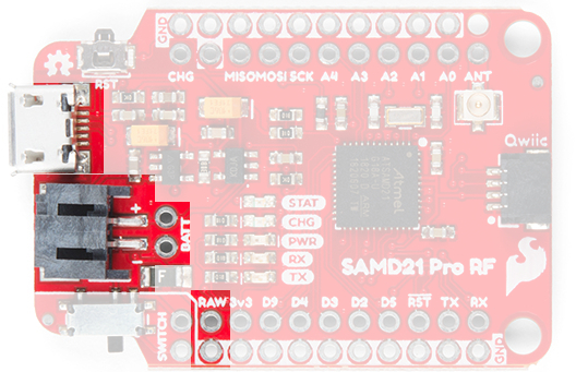
Warning: Powering the SAMD21 Pro RF is easy but the onboard low noise, low dropout voltage regulator can not handle anything above 6V. Please be attentive with how you power it.
Pinout
Logic Levels: Keep in mind that this is a 3.3V system, which interfaces nicely with our Qwiic environment and other 3.3V devices. If you are using the SAMD21 Pro RF with your external 5V devices, we recommend adding a level shifter in between.
Below is a table with every pin on the SparkFun SAMD21 Pro RF and it’s function.
| Pin | Description |
|---|---|
| RAW | Input Supply Voltage should never exceed 6V |
| GND | Ground on outside thru-holes |
| 3v3 | 3.3V OUT |
| RST | 3.3V OUT |
| D2, D3, D4, D5, D9 | Digital I/O Pins |
| A0, A1, A2, A3, A4 | Analog I/O Pins |
| RX/TX | Serial Ports |
| MOSI/MISO/SCK | SPI |
| ANT | Antennae for RFM Module |
LEDs
This product carries the full gamut of LEDs we’ve come to expect on SparkFun development boards: STAT LED, CHARGE LED, RX/TX indicators, and a Power LED. The STAT LED is on pin 13, typical on most Arduino boards. The RX and TX LEDs indicate activity on the USB serial port and are also available through the Arduino IDE using the macros PIN_LED_RXL and PIN_LED_TXL as your pin declarations. These LEDs are active-low, so writing the pin HIGH will turn the LED off. The charge LED is controlled by the onboard MCP73831 and lights up when a battery is being charged and turns off when the battery is full.
Image may be NSFW.
Clik here to view.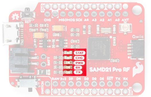
RFM95W Radio Module
The RFM95W Radio Module is a powerful but low power module that allows for point to point radio communication. It also has the capability of utilizing the Long Range Wide Area Network (LoRaWan) by closing two LoRaWAN labeled jumpers on the underside.
Image may be NSFW.
Clik here to view.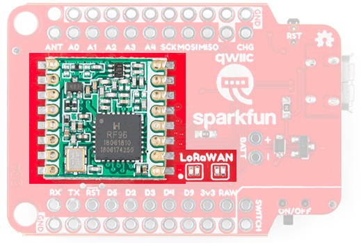
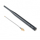
Antenna
There are two options for an antenna on the SAMD21 Pro RF, a wire and a u.FL connector. The plated through hole and the connector are both labeled by the same ANT silk on the topside of the product.
Image may be NSFW.
Clik here to view.
When using the through hole for your antenna, notice the unplated hole just above it. The purpose of this hole is to thread the wire antenna through it so that it takes the stress of daily wear and tear off of the solder joint. Woot!
Image may be NSFW.
Clik here to view.
How Much Wire Length Do I Need?
We have you covered, here are wire lengths for quarter-wave antennas at 915MHz and 868MHz:
| Country | Frequency | Length (inches) | Length (mm) |
| Americas | 915 MHz | 3.07" (3 + 1/16") | 78mm |
| Europe | 868 MHz | 3.38" (3 + 3/8") | 86mm |
u.FL Antenna
Another option is to connect a LoRa Antenna to the u.FL connector.
Image may be NSFW.
Clik here to view.
Qwiic Connector
On the tail end of the product is a Qwiic connector. If you are not familiar with the system, you can get a full rundown here. In short the Qwiic system is an I2C environment of products that can be rapidly prototyped because we’ve broken out the I2C lines: ground, power, clock, and data, to a four pin JST connector. There’s no need for solder or a soldering iron and our catalog of products with a Qwiic connector are growing rapidly.
Image may be NSFW.
Clik here to view.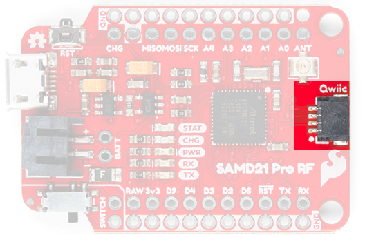
Here the SAMD21 ProRF is connected to the Qwiic Triple Axis Accelerometer.
Image may be NSFW.
Clik here to view.
Hardware Limitations and Current Capabilities
This topic is mentioned in detail under the SAMD21 Dev/Mini Breakout Hookup Guide but it’s worth restating again here. Depending on the task it’s given, the SAMD21’s core will usually consume between 3-17mA. There should be plenty of juice left from the 600mA 3.3V regulator to power other sensors or components off the board’s 3.3V supply rail.
Each I/O pin can sink up to 10mA and source up to 7mA, with one caveat: each cluster of I/O is limited to sourcing 14mA or sinking 19.5mA. The GPIO clusters are:
| Cluster | GPIO | Cluster Supply (Pin) | Cluster Ground (Pin) |
|---|---|---|---|
| 1 | SWCLK, SWDIO | VDDIN (44) | GND (42) |
| 2 | 30, 31 (USB_HOST_EN, TX_LED) | VDDIN (44) VDDIO (36) | GND (42) GND (35) |
| 3 | D2, D5, D6, D7, D10, D11, D12, D13, D38 SCL, SDA, MISO, SCK, MOSI (USB_D-, USB_D+) | VDDIO (36) VDDIO (17) | GND (35) GND (18) |
| 4 | D0, D1, D3, D4 | VDDIO (17) | GND (18) |
| 5 | A1, A2, A3, A4 D8, D9 | VDDANA (6) | GNDANA (5) |
| 6 | A0, A5, AREF (RX_LED, RTC1, RTC2) | VDDANA (6) | GNDANA (5) |
If for example, you’re sourcing current to four LEDs tied to pins 0, 1, 3, and 4 (cluster 4), the sum of that current must be less than 14mA (~3.5mA per LED). On a related note, Cluster 3 is mostly occupied by the Radio’s various inputs: interrupt, chip select, and reset as well as the Qwiic Connector.
Setting Up Arduino
Update Arduino! This setup requires at least Arduino version 1.6.4 or later. We've tested it on the latest version – 1.8.5. If you're running an older version of Arduino, consider visiting arduino.cc to get the latest, greatest release.
While the SAMD21 is powerful and completely supported by the Arduino IDE. This following section will list every step required for installing the SparkFun SAMD21 Pro RF into the Arduino IDE.
Install Arduino SAMD Boards
First, we’ll install the SAMD board definitions via the Boards Manager in the Arduino IDE which contains a variety of tools, including low-level ARM Cortex libraries full of generic code, arm-gcc to compile your code, and bossa to upload over the bootloader.
To install the Arduino SAMD board definitions, navigate to your board manager (Tools>Board>Boards Manager…), then find an entry for Arduino SAMD Boards (32-bits ARM Cortex-M0+). Select it, and install the latest version. At the time of this Hookup Guide, version 1.6.19 was used.
Image may be NSFW.
Clik here to view.
Downloading and installing the tools may take a couple minutes – arm-gcc in particular will take the longest, it’s about 250MB unpacked! Once installed. the Installed text will appear next to the SAMD boards list entry. Let’s continue…
Install SparkFun Board Definition
Open your Arduino preferences (File>Preferences). Then find the Additional Board Manager URLs text box, and paste the link listed below in the field encapsulated in the red box:
https://raw.githubusercontent.com/sparkfun/Arduino_Boards/master/IDE_Board_Manager/package_sparkfun_index.json
Image may be NSFW.
Clik here to view.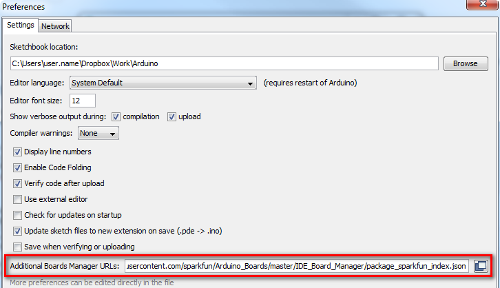
If you’ve done this before with different development boards, then you can add the SparkFun link text to the end of the text, just add a comma between seperate links or click on the small square to the right of the field and add it to the bottom of the list. Now hit OK, and travel back to the Boards Manager menu. You’ll now see a new entry for SparkFun SAMD Boards. If you don’t see it, close the boards manager and open it again. ¯\(ツ)/¯.
Image may be NSFW.
Clik here to view.
This installation should be much faster; you’ve already done the heavy lifting in the previous section.
Select the Board and Serial Port
Once the board is installed, you should see a new entry in your Tools>Board list: SparkFun SAMD21 Pro RF.
Image may be NSFW.
Clik here to view.
Finally, select your SAMD21 Pro RF Board’s port. Navigate back up to the Tool>Port menu. The port menu may magically know which of your ports (if you have more than one) are the SAMD21 board. On a Windows machine, the serial port should come in the form of “COM#”. On a Mac or Linux machine, the port will look like “/dev/cu.usbmodem####”.
Point to Point Radio Arduino Examples
Note: This example assumes you are using the latest version of the Arduino IDE on your desktop. If this is your first time using Arduino, please review our tutorial on installing the Arduino IDE. If you have not previously installed an Arduino library, please check out our installation guide.
For this example we’ll be utilizing the Radio Head Library to utilize the RFM96W Radio Module. You can download the Radio Head library from its' GitHub repo, or click the link below. While you’re clicking on buttons, all of the Arduino example code can be downloaded by downloading it from the SAMD21 Pro RF Arduino Examples GitHub repo or clicking the second button below.
Download RadioHead Arduino Library (ZIP)
Download SAMD21 Pro RF Arduino Examples (ZIP)
One last thing before we go any farther. The SAMD21 is a highly versatile chip and we’ve taken advantage of that fact by creating two seperate UART lines, one that interfaces with the computer through the micro-B and another one broken out on the RX/TX header on the side of the board. To communicate to the Arduino IDE’s serial monitor, we’ll be using the statement SerialUSB, rather than the normal Serial that you might be used to. Are they different? Nope! Just different nomenclature for different UART lines.
Point to Point Radio Arduino Examples
Radio Server
Note: For the following two examples to work you'll need one radio module to send your message and another to hear and respond. This example uses two SAMD21 Pro RF's communicating to each other.
Assuming that the Arduino library you downloaded and installed is working correctly, let’s move onto our first example. This example and the following example build off of the sample code provided by the RadioHead library but has been tailored for the SAMD21 Pro RF.
language:c
#include <SPI.h>

//Radio Head Library:
#include <RH_RF95.h>

// We need to provide the RFM95 module's chip select and interrupt pins to the
// rf95 instance below.On the SparkFun ProRF those pins are 12 and 6 respectively.
RH_RF95 rf95(12, 6);

int LED = 13; //Status LED on pin 13

int packetCounter = 0; //Counts the number of packets sent
long timeSinceLastPacket = 0; //Tracks the time stamp of last packet received
// The broadcast frequency is set to 921.2, but the SADM21 ProRf operates
// anywhere in the range of 902-928MHz in the Americas.
// Europe operates in the frequencies 863-870, center frequency at
// 868MHz.This works but it is unknown how well the radio configures to this frequency:
//float frequency = 864.1;
float frequency = 921.2;

void setup()
{
  pinMode(LED, OUTPUT);

  SerialUSB.begin(9600);
  // It may be difficult to read serial messages on startup. The following
  // line will wait for serial to be ready before continuing. Comment out if not needed.
  while(!SerialUSB);
  SerialUSB.println("RFM Server!");

  //Initialize the Radio.
  if (rf95.init() == false){
    SerialUSB.println("Radio Init Failed - Freezing");
    while (1);
  }
  else{
  // An LED indicator to let us know radio initialization has completed.
    SerialUSB.println("Receiver up!");
    digitalWrite(LED, HIGH);
    delay(500);
    digitalWrite(LED, LOW);
    delay(500);
  }

  rf95.setFrequency(frequency);

  // Transmitter power can range from 14-20dbm.
  rf95.setTxPower(14, true);
}

void loop()
{
  if (rf95.available()){
    // Should be a message for us now
    uint8_t buf[RH_RF95_MAX_MESSAGE_LEN];
    uint8_t len = sizeof(buf);

    if (rf95.recv(buf, &len)){
      digitalWrite(LED, HIGH); //Turn on status LED
      timeSinceLastPacket = millis(); //Timestamp this packet

      SerialUSB.print("Got message: ");
      SerialUSB.print((char*)buf);
      //SerialUSB.print(" RSSI: ");
      //SerialUSB.print(rf95.lastRssi(), DEC);
      SerialUSB.println();

      // Send a reply
      uint8_t toSend[] = "Hello Back!";
      rf95.send(toSend, sizeof(toSend));
      rf95.waitPacketSent();
      SerialUSB.println("Sent a reply");
      digitalWrite(LED, LOW); //Turn off status LED

    }
    else
      SerialUSB.println("Recieve failed");
  }
  //Turn off status LED if we haven't received a packet after 1s
  if(millis() - timeSinceLastPacket > 1000){
    digitalWrite(LED, LOW); //Turn off status LED
    timeSinceLastPacket = millis(); //Don't write LED but every 1s
  }
}
Radio Client
language:c
/*
  Both the TX and RX ProRF boards will need a wire antenna. We recommend a 3" piece of wire.
  This example is a modified version of the example provided by the Radio Head
  Library which can be found here:
  www.github.com/PaulStoffregen/RadioHeadd
*/

#include <SPI.h>

//Radio Head Library:
#include <RH_RF95.h>

// We need to provide the RFM95 module's chip select and interrupt pins to the
// rf95 instance below.On the SparkFun ProRF those pins are 12 and 6 respectively.
RH_RF95 rf95(12, 6);

int LED = 13; //Status LED is on pin 13

int packetCounter = 0; //Counts the number of packets sent
long timeSinceLastPacket = 0; //Tracks the time stamp of last packet received

// The broadcast frequency is set to 921.2, but the SADM21 ProRf operates
// anywhere in the range of 902-928MHz in the Americas.
// Europe operates in the frequencies 863-870, center frequency at 868MHz.
// This works but it is unknown how well the radio configures to this frequency:
//float frequency = 864.1;
float frequency = 921.2; //Broadcast frequency

void setup()
{
  pinMode(LED, OUTPUT);

  SerialUSB.begin(9600);
  // It may be difficult to read serial messages on startup. The following line
  // will wait for serial to be ready before continuing. Comment out if not needed.
  while(!SerialUSB);
  SerialUSB.println("RFM Client!");

  //Initialize the Radio.
  if (rf95.init() == false){
    SerialUSB.println("Radio Init Failed - Freezing");
    while (1);
  }
  else{
    //An LED inidicator to let us know radio initialization has completed.
    SerialUSB.println("Transmitter up!");
    digitalWrite(LED, HIGH);
    delay(500);
    digitalWrite(LED, LOW);
    delay(500);
  }

  // Set frequency
  rf95.setFrequency(frequency);

   // Transmitter power can range from 14-20dbm.
   rf95.setTxPower(14, true);
}


void loop()
{
  SerialUSB.println("Sending message");

  //Send a message to the other radio
  uint8_t toSend[] = "Hi there!";
  //sprintf(toSend, "Hi, my counter is: %d", packetCounter++);
  rf95.send(toSend, sizeof(toSend));
  rf95.waitPacketSent();

  // Now wait for a reply
  byte buf[RH_RF95_MAX_MESSAGE_LEN];
  byte len = sizeof(buf);

  if (rf95.waitAvailableTimeout(2000)) {
    // Should be a reply message for us now
    if (rf95.recv(buf, &len)) {
      SerialUSB.print("Got reply: ");
      SerialUSB.println((char*)buf);
      //SerialUSB.print(" RSSI: ");
      //SerialUSB.print(rf95.lastRssi(), DEC);
    }
    else {
      SerialUSB.println("Receive failed");
    }
  }
  else {
    SerialUSB.println("No reply, is the receiver running?");
  }
  delay(500);
}
The “Server” and “Client” nomenclature may be a bit misleading. It might be more accurate to say “call” and “call-back”. None the less, there are a few notable changes made from the original examples.
- Chip Select and Interupt Pins
RH_RF95 rf95(12, 6)– Pin 12 and pin 6 are the assigned pins that run to the RM95 Radio Module’s chip select and interrupt pins.
- SerialUSB or Serial?
while(!SerialUSB)– When the SAMD21 Pro RF starts up, it’s not always a smooth transition and messages meant for the serial monitor will get missed. This line will hold your code hostage until you open the serial monitor at which point it will continue on. We have two UART lines for this microcontroller, the one that communicates with the serial monitor is called using the keyword SerialUSB.
- Frequency Select
rf95.setFrequency(frequency)– The default frequency is kind of random, 921.2 but it falls within the American ISM band: 902-928MHz. If you’re in Europe, that band is 863-870MHz. You’ll find the variable “frequency” is set a little higher up in the code.
After you upload the code to two SAMD21 Pro RF’s, open a serial monitor set at 9600. You should see the following readout in the serial monitors!
Image may be NSFW.
Clik here to view.
Click the image for a closer look at the output.
LoRaWAN Arduino Example
The Internet of Things “Hello World” - Node Example
For this example, we’ll be setting up the SAMD21 Pro RF as a node using a library written by Matthijs Kooijman which is a modified version of “IBM’s LMIC (LoraMAC-in-C)” library. You can download it through the Arduino Library Manager under “LMIC-Arduino”. You can also download and manually install it from the GitHub Repository, or click the button below to manually install it from there.
Arduino LMIC Library Download (ZIP)
This example requires that you have an account with The Things Network and a nearby gateway. Read the brief introduction above to learn about nodes, gateways, and network servers. First, we’ll need an account at The Things Network which will provide us our network server to manage, graph, and/or look at our data in the case of our “Hello World” example below. On the front page of the website there’s a map that shows active gateways in your area. If you don’t have a gateway nearby, you can set one up using SparkFun’s ESP32 1-Ch Gateway, using this excellent set up guide here. This is the gateway that I chose to use for this example.
Registering Your Node
Before you can upload with the SAMD21 Pro RF, you’ll need to sign up for an account on their website. Registering with their website is free, and allows the network to generate the necessary keys which identify your projects and nodes.
Image may be NSFW.
Clik here to view.
You’ll notice that there’s no option to just add a node, that’s because The Things Network needs to know what application to associate with your device. Therefore, you’ll need to start by creating an application. Clicking on the Applications button will take you to a page that looks like this:
Image may be NSFW.
Clik here to view.
This would usually be a list of all your applications, but The Things Network automatically recognizes that you don’t have any applications yet and suggests that you add one. You can add an application either by clicking that link or clicking on “add application” in the upper right corner. Both of those links will take you to this page:
Image may be NSFW.
Clik here to view.
Give your application an Application ID (identifier); this is the name that The Things Network will use to distinguish it from the other applications. It can only contain lowercase letters, numbers, and dashes. The description field is for humans, so take a moment to write a sentence about what your app does. In this case, I’ve just written that it’s an example application. The EUI will be issued by the network, so there’s no need to type anything there. Finally, select the handler that you want your application to be registered to. Essentially, these are instances of the network server in different physical locations around the world. All applications will talk to all network servers, but to minimize latency, it’s best to select the handler closest to your gateway. SparkFun is located in Colorado, so I chose “ttn-handler-us-west,” which I assume is in California somewhere. Click the Add Application button and you’ll be taken to your freshly generated application console.
Image may be NSFW.
Clik here to view.
Now that you’ve created an application, you can register a device to it. Scroll down to the Devices section of the application page and you will see your current device count (which is none) as well as options to register a device and to manage devices. Click on register device.
Image may be NSFW.
Clik here to view.
This form is pretty similar to the Register an Application page, but you have a little less to do. Give your device a Device ID, the same rules apply as did with the Application ID. Then click the little crossed arrows beside the Device EUI field, this lets TTN know that you want them to generate an EUI for you. Now just click on the Register button at the bottom of the form.
Image may be NSFW.
Clik here to view.
And now you’ve been taken to your brand new device console. Under the section labeled Device Overview you’ll notice the Application ID and Device ID that you set earlier. Under Activation Method it will likely say “OTAA,” which stands for Over The Air Activation. This is a secure, transportable method of activating LoRaWAN devices, whereby the device uses a known application key to request new session keys whenever it wants to join the network. This is the preferred method for activating a production device, but for prototyping it’s usually easier to hard code the session keys into your device. In order to do this, we’ll need to set the activation method to “ABP” or Activation By Personalization. To do this, click on the Settings tab in the upper right-hand corner of the device page and you’ll be taken to the device settings menu. Partway down the page you should find an option to change the activation method.
Image may be NSFW.
Clik here to view.
Click on “ABP,” and then save your settings. When you return to the Overview page, you should now see some extra fields in the Device Overview:
Image may be NSFW.
Clik here to view.
We’ll need these keys to program your SAMD21 Pro RF so leave this page up on your browser and let’s open up the Arduino IDE. It’s time to program the node!
Programming the SAMD21 Pro RF
This modified example takes directly from the example code provided by the library with a two changes: the function calls to “Serial” have been replaced with “SerialUSB” and changes to the pin mapping that is consistent with the SAMD21 Pro RF. Before we look at the code you’ll first need to modify the config.h file that came with the LMIC Arduino Library.
Find your Arduino libraries folder and navigate to …IBM_LMIC_framework/src/lmic/. You should find a file called config.h. Open it in any text editor and find the lines where CFG_us915 is defined. It should look like this:
language:c
//#define CFG_eu868 1
#define CFG_us915 1
// This is the SX1272/SX1273 radio, which is also used on the HopeRF
// RFM92 boards.
//#define CFG_sx1272_radio 1
// This is the SX1276/SX1277/SX1278/SX1279 radio, which is also used on
// the HopeRF RFM95 boards.
#define CFG_sx1276_radio 1
Since we’re using the 915MHz radio module in the US, you need to make sure that the line #define CFG_us915 1 is not commented out and that the line #define CFG_eu868 1 is, by prepending // as shown above. Same goes for the radio type, we want #define CFG_sx1276_radio 1 and not #define CFG_sx1272_radio 1. Notice how the first “#define” contains “eu868”, short for Europe and its center frequency. The line we un-commented contains “us915” which is undoubtedly for United States, with its center frequency at 915. With those changes made, save the config.h file and return to the Arduino IDE.
In order to make it work with your application you’ll need to copy in some keys from the Device Overview page on your TTN Console, so flip back to the browser tab with the Device Overview page loaded up.
You’ll notice that, by default, the Network Session Key and App Session Key fields are obscured for security reasons. You can click the eye icon to show the code before copying it. Also, it will be easier to copy this into the example code if you click the <> button to show the codes in “C style”, a bunch of HEX designated numbers.
You will need to copy three separate numbers into your example code from this page:
- Network Session Key =(i.e.
NWKSKEY[]) - App Session Key (i.e.
PROGMEM APPSKEY[]) - Device Address (i.e.
DEVADDR)
Here’s a diagram explaining which field on this page corresponds to which constant in the example code:
Image may be NSFW.
Clik here to view.
Click the image for a closer look.
Notice the three lines at the top of the code that say “Network Session Key Here”, “Application Key Here”, and “Device Address here”. These lines can be replaced by the keys from the website.
language:c
#include <lmic.h>
#include <hal/hal.h>
#include <SPI.h>

// LoRaWAN NwkSKey, network session key
static const PROGMEM u1_t NWKSKEY[16] ={ NETWORK SESSION KEY HERE };

// LoRaWAN AppSKey, application session key
static const u1_t PROGMEM APPSKEY[16] = { APPLICATION KEY HERE };

// LoRaWAN end-device address (DevAddr)
static const u4_t DEVADDR =  DEVICE ADDRESS HERE;

// These callbacks are only used in over-the-air activation, so they are
// left empty here (we cannot leave them out completely unless
// DISABLE_JOIN is set in config.h, otherwise the linker will complain).
// Well alright......
void os_getArtEui (u1_t* buf) { }
void os_getDevEui (u1_t* buf) { }
void os_getDevKey (u1_t* buf) { }

static uint8_t mydata[] = "Hello, world!";
static osjob_t sendjob;

// Schedule TX every this many seconds (might become longer due to duty
// cycle limitations).
const unsigned TX_INTERVAL = 5;

// Pin mapping
const lmic_pinmap lmic_pins = {
    .nss = 12,//RFM Chip Select
    .rxtx = LMIC_UNUSED_PIN,
    .rst = 7,//RFM Reset
    .dio = {6, 10, 11}, //RFM Interrupt, RFM LoRa pin, RFM LoRa pin
};

void onEvent (ev_t ev) {
    SerialUSB.print(os_getTime());
    SerialUSB.print(": ");
    switch(ev) {
        case EV_SCAN_TIMEOUT:
            SerialUSB.println(F("EV_SCAN_TIMEOUT"));
            break;
        case EV_BEACON_FOUND:
            SerialUSB.println(F("EV_BEACON_FOUND"));
            break;
        case EV_BEACON_MISSED:
            SerialUSB.println(F("EV_BEACON_MISSED"));
            break;
        case EV_BEACON_TRACKED:
            SerialUSB.println(F("EV_BEACON_TRACKED"));
            break;
        case EV_JOINING:
            SerialUSB.println(F("EV_JOINING"));
            break;
        case EV_JOINED:
            SerialUSB.println(F("EV_JOINED"));
            break;
        case EV_RFU1:
            SerialUSB.println(F("EV_RFU1"));
            break;
        case EV_JOIN_FAILED:
            SerialUSB.println(F("EV_JOIN_FAILED"));
            break;
        case EV_REJOIN_FAILED:
            SerialUSB.println(F("EV_REJOIN_FAILED"));
            break;
        case EV_TXCOMPLETE:
            SerialUSB.println(F("EV_TXCOMPLETE (includes waiting for RX windows)"));
            if (LMIC.txrxFlags & TXRX_ACK)
              SerialUSB.println(F("Received ack"));
            if (LMIC.dataLen) {
              SerialUSB.println(F("Received "));
              SerialUSB.println(LMIC.dataLen);
              SerialUSB.println(F(" bytes of payload"));
            }
            // Schedule next transmission
            os_setTimedCallback(&sendjob, os_getTime()+sec2osticks(TX_INTERVAL), do_send);
            break;
        case EV_LOST_TSYNC:
            SerialUSB.println(F("EV_LOST_TSYNC"));
            break;
        case EV_RESET:
            SerialUSB.println(F("EV_RESET"));
            break;
        case EV_RXCOMPLETE:
            // data received in ping slot
            SerialUSB.println(F("EV_RXCOMPLETE"));
            break;
        case EV_LINK_DEAD:
            SerialUSB.println(F("EV_LINK_DEAD"));
            break;
        case EV_LINK_ALIVE:
            SerialUSB.println(F("EV_LINK_ALIVE"));
            break;
         default:
            SerialUSB.println(F("Unknown event"));
            break;
    }
}

void do_send(osjob_t* j){
    // Check if there is not a current TX/RX job running
    if (LMIC.opmode & OP_TXRXPEND) {
        SerialUSB.println(F("OP_TXRXPEND, not sending"));
    }
    else{
        // Prepare upstream data transmission at the next possible time.
        LMIC_setTxData2(1, mydata, sizeof(mydata)-1, 0);
        SerialUSB.println(F("Packet queued"));
    // Next TX is scheduled after TX_COMPLETE event.
    }
}

void setup() {
    SerialUSB.begin(115200);
    // Serial communication on startup is not consistent on the SAMD21. The
    // following line waits for the serial monitor to be opened before
    // continuing. Uncomment if not needed.
    while(!SerialUSB);
    SerialUSB.println("Starting");

    // LMIC init
    os_init();
    // Reset the MAC state. Session and pending data transfers will be discarded.
    LMIC_reset();

    // Set static session parameters. Instead of dynamically establishing a session
    // by joining the network, precomputed session parameters are be provided.
    #ifdef PROGMEM
    // On AVR, these values are stored in flash and only copied to RAM
    // once. Copy them to a temporary buffer here, LMIC_setSession will
    // copy them into a buffer of its own again.
    uint8_t appskey[sizeof(APPSKEY)];
    uint8_t nwkskey[sizeof(NWKSKEY)];
    memcpy_P(appskey, APPSKEY, sizeof(APPSKEY));
    memcpy_P(nwkskey, NWKSKEY, sizeof(NWKSKEY));
    LMIC_setSession (0x1, DEVADDR, nwkskey, appskey);
    #else
    // If not running an AVR with PROGMEM, just use the arrays directly
    LMIC_setSession (0x1, DEVADDR, NWKSKEY, APPSKEY);
    #endif

    #if defined(CFG_us915)
    // NA-US channels 0-71 are configured automatically
    // but only one group of 8 should (a subband) should be active
    // TTN recommends the second sub band, 1 in a zero based count.
    // https://github.com/TheThingsNetwork/gateway-conf/blob/master/US-global_conf.json
    LMIC_selectSubBand(1);
    #endif

    // Disable link check validation
    LMIC_setLinkCheckMode(0);

    // TTN uses SF9 for its RX2 window.
    LMIC.dn2Dr = DR_SF9;

    // Set data rate and transmit power for uplink (note: txpow seems to be ignored by the library)
    LMIC_setDrTxpow(DR_SF7,14);

    // Start job
    do_send(&sendjob);
}

void loop() {
    os_runloop_once();
}
Below are a few modifications to the original code that have been made to tailor it to the SAMD21 Pro RF.
- SerialUSB
while(!SerialUSB)– When the SAMD21 Pro RF starts up, it’s not always a smooth transition and messages meant for the serial monitor will get missed. This line will hold your code hostage until you open the serial monitor at which point it will continue on. The SAMD21 Pro RF has two UART lines, SerialUSB references the one that communicates with the computer via the Micro-B connector.
We’ve also had to change the pin mappings to be consitent with the reset, chip select, interrupt, and LoRaWAN lines of the RFM95W module.
language:c
const lmic_pinmap lmic_pins = {
    .nss = 12,//RFM Chip Select
    .rxtx = LMIC_UNUSED_PIN,
    .rst = 7,//RFM Reset
    .dio = {6, 10, 11}, //RFM Interrupt, RFM LoRa pin, RFM LoRa pin
};
Close the LoRaWAN Jumpers
One last thing. On the underside of the SAMD21 Pro RF there are two jumpers labeled LoRaWAN. Closing these jumpers will tell the module that we’re broadcasting in the modulation scheme unique to LoRaWAN.
Image may be NSFW.
Clik here to view.
Upload the code and let’s go back to the website and see what it looks like!
Decode Your Data
You may have noticed in the Application Data window that your payload is shown in raw bytes. In order to see “Hello, World!” encoded in ASCII, the way you sent it, you’ll need to decode the payload. The Things Network includes tools for doing this right in the console! Navigate to the Application Overview page for your application and click on the Payload Formats tab. This menu allows you to write functions which will be applied to all incoming packets for this application.
Image may be NSFW.
Clik here to view.
So let’s write our own decoder. We need to take the raw byte data and return a string that contains all of the characters corresponding to each byte. Take a look at this solution and then we’ll walk through it:
language:js
function Decoder(bytes, port) {

return {
    ASCII: String.fromCharCode.apply(null, bytes)
};

}
Decoder is a Javascript function that The Things Network has already set up for us. It takes two arguments called bytes, an array containing our payload, and port, the LoRaWAN™ “FPort” of the packet. FPort identifies the end application or service that the packet is intended for. Port 0 is reserved for MAC messages. We don’t need to know anything about the port number for our example.
We can return any value that we want from the Decoder function and it will appear alongside our payload in the Application Data window. In the example above, I’ve created a new property called “ASCII” which is equal to String.fromCharCode.apply(null, bytes). To break this down a little more, we’re returning a new String object called “ASCII,” and we’re using the Javascript apply() method to call fromCharCode() with the argument bytes and stuff the result into our new String. The fromCharCode() method simply steps through each byte in the array bytes (which, remember, contains our payload) and returns the ASCII character represented by that character code.
After copying the above code into your decoder function, scroll down and click the save payload functions button. Now return to the Application Data window and you should see that all packets received after the decoder function was changed now have a new property:
Image may be NSFW.
Clik here to view.
Our packet has been decoded! Neat!
Using the Data
Okay, so now you have data coming into your TTN application but what do you do with it? Well, you have a few options:
APIs
The most basic endpoints for interacting with The Things Network programmatically are the TTN Handler APIs or “application programming interfaces”. There are two APIs, the Data API and the Application Manager API. The Data API allows you to send and receive messages, making it the most useful for most applications. You can interact with this API using the MQTT protocol. The Application Manager API is available directly through HTTP and lets you manage applications, gateways, and devices. It’s much more powerful than the Data API and is mostly intended to allow endpoint applications to perform device management.
SDKs
The Things Network has also created several Software Developer Kits (SDKs) which allow you to program your application without having to interact directly with the low level APIs. SDKs are available for several popular languages.
Integrations
Finally, the easiest way to access your data and put it to work is with The Things Network’s various platform integrations. Integrations allow you to pass your application data directly to another platform such as AWS IoT, Cayenne, EVRYTHNG, or IFTTT. From there, you can use those platforms to interact with your data.
Resources and Going Further
The SAMD21 Pro RF is a powerful microcontroller with LoRaWAN capabilities. To best take advantage of it, plug in a LiPo battery and a Qwiic enabled sensor. Perhaps you don’t have a gateway nearby, or have found that they can be quite expensive? Look no further than our ESP32 LoRa 1 Ch Gateway with its excellent hookup guide.
- Hardware
- Schematic (PDF)– PDF schematic
- Eagle Files (ZIP)– PCB design files
- Datasheets
- MCP73831 (PDF)– Datasheet for the LiPo Charger IC
- RFM95W (PDF)– Datasheet for the RFM95W LoRa radio module
- Product Repository– GitHub repository where you can find all of our latest hardware and software design files.
Software
- Libraries
- Radio Head
- Arduino-LMIC– LoRaMAC-in-C (LMIC) Arduino library used to create LoRaWAN devices.
- Arduino Example Codes– All the examples used in this tutorial.
- Libraries
What is LoRaWAN?
- Introduction to LoRaWAN– Sparkfun’s beginner’s guide to everything the Long Range Wide Area Network known as LoRaWAN.
- LoRa Alliance™
- LoRa and Pycom
- The Things Industries– Free to use LoRa Network Server
- The Things Network
- resin.io– Alternative free to use LoRa Network Server
Need some inspiration for your next project? Check out some of these related tutorials:
SparkFun Blocks for Intel® Edison - OLED Block
Experiment Guide for the Johnny-Five Inventor's Kit
How to Use Remote Desktop on the Raspberry Pi with VNC
LoRaWAN with ProRF and The Things Network
learn.sparkfun.com | CC BY-SA 3.0 | SparkFun Electronics | Niwot, Colorado