Qwiic OpenLog Hookup Guide a learn.sparkfun.com tutorial
Available online at: http://sfe.io/t865
Introduction
The SparkFun Qwiic OpenLog is the smarter and better looking cousin to the extremely popular OpenLog. We’ve ported the original serial based interface to I2C. Now you can daisy chain multiple I2C devices and log them all without taking up your serial port. Pop in a microSD card, write some simple code, and your data will be recorded to a text file on the microSD card.

Materials Required
In order to fully work through this tutorial, you will need the following parts. You may not need everything though, depending on what you have. Add it to your cart, read through the guide, and adjust the cart as necessary.
Recommended Reading
If you are not familiar or comfortable with the following concepts, we recommend reading through these before continuing on with the Qwiic OpenLog Hookup Guide.
Serial Communication
Serial Terminal Basics
Hardware Overview
Power
The Qwiic OpenLog runs at the following settings:
| VCC Input | 3.3V-12V (Recommended 3.3V-5V) |
|---|---|
| RXI Input | 2.0V-3.8V |
| TXO Output | 3.3V |
| Idle Current Draw | ~2mA-5mA (w/out microSD card), ~5mA-6mA (w/ microSD card) |
| Active Writing Current Draw | ~20-23mA (w/ microSD card) |
The Qwiic OpenLog’s current draw is about 20mA to 23mA when writing to a microSD. Depending on the size of the microSD card and its manufacturer, the active current draw can vary when the OpenLog is writing to the memory card. Increasing the baud rate will also pull more current.
Register Map
The Qwiic Open Log implements a register map type set up if you’d like to create your own library.

Having a hard time seeing? Click the image for a closer look.
Microcontroller
Like its predecessor, the Qwiic OpenLog runs off of an onboard ATmega328, running at 16MHz thanks to the onboard crystal. The ATmega328 has the Optiboot bootloader loaded on it, which allows the OpenLog to be compatible with the “SparkFun Redboard” board setting in the Arduino IDE.
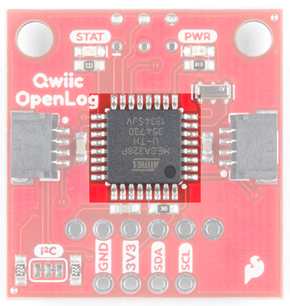
The brain of the Qwiic OpenLog.
Interface
Qwiic Connectors
The primary interface with the Qwiic OpenLog are the Qwiic connectors on either side of the board. If you aren’t familiar with the Qwiic system, you are in for a treat! The Qwiic system utilizes I2C protocol to allow multiple “slave” digital integrated circuits (“chips”) to communicate with one or more “master” chips with a mere two wires. Check out all the benefits of the Qwiic System here.
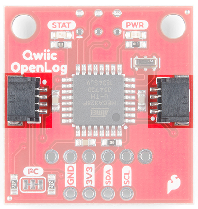
Qwiic Connectors
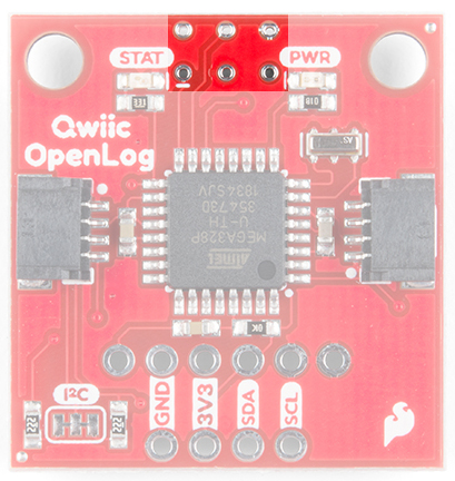
FTDI Header Pins
While the Qwiic OpenLog retains the broken out FTDI header pins, they pins are used specifically for reprogramming the firmware. All logging communication happens through the Qwiic lines and associated broken out pins.
FTDI Header Pins
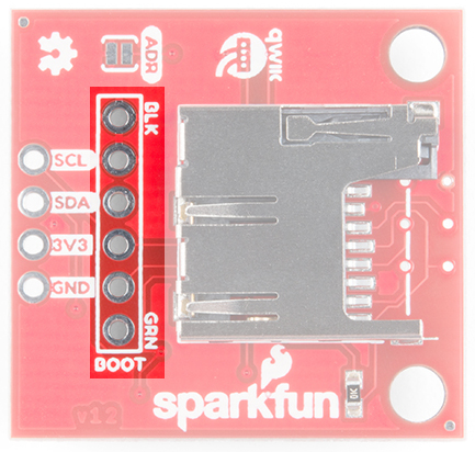
SPI
There are also six SPI test points broken out on the opposite side of the board. You can also use these to reprogram the bootloader on the ATmega328.
SPI Test Points
microSD Card
The final interface for communicating with the Qwiic OpenLog is the microSD card itself. To communicate, the microSD card requires SPI pins. Not only is this where the data is stored by the OpenLog, but you can also update the OpenLog’s configuration via the config.txt file on the microSD card.
All data logged by the OpenLog is stored on the microSD card. The OpenLog works with microSD cards that involve the following features:
- 64MB to 32GB
- FAT16 or FAT32
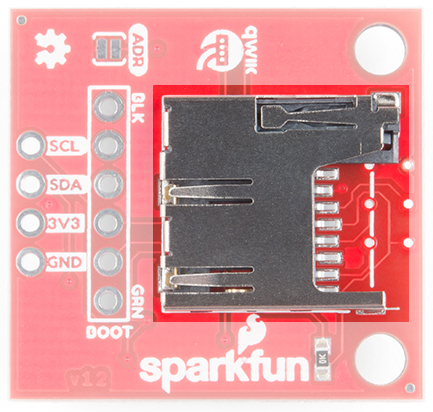
microSD Slot on the bottom of the Qwiic OpenLog
Status LED
There are two LEDs on the OpenLog to help you with troubleshooting.
- STAT - This green LED is connected to Arduino D13 (Serial Clock Line/ ATmega328 PB5). This LED only blinks when the SPI interface is active. You will see it flash when the OpenLog records data to the microSD card.
- PWR - This red indicator LED is attached to Arduino D5 (ATmega328 PD5) and lights when the board is active and functioning.
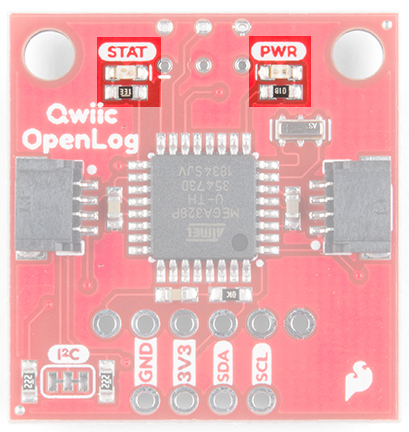
Status and Power LEDs on the Qwiic OpenLog
Hardware Hookup
If you’ve purchased the SparkFun RedBoard Qwiic, hardware hookup is as simple as plugging in your Qwiic cable!

If, however, you are using an older SparkFun RedBoard, you’ll need an assembled Qwiic Shield, so if you haven’t done that yet, now would be the time to head on over to that tutorial.
Qwiic Shield for Arduino & Photon Hookup Guide
October 19, 2017
Arduino Sketches
There are eleven examples in the Qwiic OpenLog Arduino Library that can be used when connected to a Qwiic OpenLog. These Arduino functions replace the serial command communication that occurred on the previous version of the OpenLog. These example files are named such that their functions should be self-explanatory, but in case you want more information, see the descriptions below. Head on over to the GitHub Page or feel free to download the library here!
SparkFun Qwiic OpenLog Arduino Library
Example1_WritingLog– This example shows how to record various text and variables to Qwiic OpenLog.
Example2_AppendFile– Arduino sketch showing how to append text to the end of File. If File does not exist when this function is called, the file will be created.
Example3_CreateFile– This example shows how to create a new file named File in the current directory. Standard 8.3 filenames are supported. For example, “87654321.123” is acceptable, while “987654321.123” is not.
Example4_ReadFileSize– This example shows how to record some strings to a default log, check the size of a given file name, and if the given file doesn’t exist, say so.
Example5_ReadFile– This example shows how to record some strings to a default log, check the size of a given file name, if that given file doesn’t exist, create it with random characters, and read back the contents of the given file (containing random characters)
Example6_MakeDirectory– This example shows how to create a directory, move into that directory called MONDAY, create a sub directory within MONDAY called LOGS, and create and write to a file inside MONDAY.
Example7_ReadDirectoryContents– This example shows how to read the files in a given directory. You can use wildcards if desired. This is handy for listing a certain type of file such as .LOG or LOG01.TXT.
Example8_RemoveDirectory– This example shows how to create a directory, create some files there, delete a specific file, delete *.TXT, and remove the directory we created.
Example9_ReadVersion– This example shows how to read the firmware version of Qwiic OpenLog.
Example10_CheckStatus– This example shows how to read the status byte of the OpenLog.
Example11_ChangeAddress– This example shows how to change the I2C address of the Qwiic OpenLog. It’s easy to change the I2C address. If you forget what the address is you can use the I2CScan Example to re-discover it. You can also close the ADR jumper on the board. This will force the I2C address to 0x29 regardless of any other setting or command.
Valid I2C addresses are 0x08 to 0x77 (inclusive):
Firmware
The Qwiic OpenLog has two primary pieces of software on board: the bootloader and the firmware.
Arduino Bootloader
You can treat the Qwiic OpenLog just like a SparkFun Redboard when uploading example code or new firmware to the board.
If you end up bricking your Qwiic OpenLog and need to reinstall the bootloader, you will also want to upload Optiboot onto the board. Please check out our tutorial on installing an Arduino Bootloader for more information.
Compiling and Loading Firmware onto the Qwiic OpenLog
If for any reason you need to update or reinstall the firmware on your OpenLog, the following process will get your board up and running.
First, download the Qwiic OpenLog firmware. You can go to the Qwiic OpenLog GitHub Page or download via the button here:
Download OpenLog Firmware (ZIP)
Once you have the firmware downloaded, install the libraries into Arduino. If you are unsure how to manually install the libraries in the IDE, please refer to the link above.
Download SerialPort (ZIP)Download SdFat)
If you haven’t yet, connect your OpenLog to the computer via an FTDI board. Please double check the example circuit if you are not sure how to do this properly. You will likely need to solder headers to the FTDI pins in order to access them. See our soldering tutorial if you need help here.
Open the OpenLog sketch you would like to upload under Tools>Board menu, select the “Arduino Redboard”, and select the proper COM port for your FTDI board under Tools>Port.
Upload the code.
That’s it! Your OpenLog is now programmed with new firmware. You can now open up a serial monitor and interact with the OpenLog. On power up, you will see either 12> or 12<. 1 indicates the serial connection is established, 2 indicates the SD card has successfully initialized and > indicates OpenLog is ready to receive commands.
Configuration File
The configuration file is not as relevant with the updated Qwiic OpenLog as it was with its predecessor. When you open the config file, you will see the I2C address, escape character, the number of escape characters, and the mode. You can edit the I2C address and the mode, but ignore the escape character and number of escape characters.
Troubleshooting
There are several different options to check if you are having issues connecting over the serial monitor, having issues with dropped characters in logs, or fighting a bricked OpenLog.
Check STAT1 LED Behavior
STAT1 LED shows different behavior for two different common errors.
- 3 Blinks: The microSD card failed to initialize. You may need to format the card with FAT/FAT16 on a computer.
- 5 Blinks: OpenLog has changed to a new baud rate and needs to be power cycled.
Double Check Subdirectory Structure
If you are using the default OpenLog.ino example, OpenLog will only support two subdirectories. You will need to change FOLDER_TRACK_DEPTH from 2 to the number of subdirectories you need to support. Once you’ve done this, recompile the code, and upload the modified firmware.
Verify the Number of Files in the Root Directory
OpenLog will only support up to 65,534 log files in the root directory. We recommend reformatting your microSD card to improve logging speed.
Verify the Size of your Modified Firmware
If you are writing a custom sketch for the OpenLog, verify that your sketch is not larger than 32,256. If so, it will cut into the upper 500 bytes of Flash memory, which is used by the Optiboot serial bootloader.
Double Check File Names
All file names should be alpha-numeric. MyLOG1.txt is ok, but Hi !e _.txt may not work.
Format your MicroSD Card
Remember to use a card with few or no files on it. A microSD card with 3.1GB worth of ZIP files or MP3s has a slower response time than an empty card.
If you did not format your microSD card on a Windows OS, reformat the microSD card and create a DOS filesystem on the SD card.
Swap MicroSD Cards
There are many different types of card manufacturers, relabeled cards, card sizes, and card classes, and they may not all work properly. We typically use a 16GB class 10 microSD card, which works well at 9600bps. If you are using an older card or anything less than class 6, you may want to try upgrading your SD card.
Add Delays Between Character Writes
By adding a small delay between Serial.print() statements, you can give OpenLog a chance to record its current buffer.
For example:
language:c
Serial.begin(115200);
for(int i = 1 ; i < 10 ; i++) {
    Serial.print(i, DEC);
    Serial.println(":abcdefghijklmnopqrstuvwxyz-!#");
}
may not log properly, as there are a lot of characters being sent right next to each other. Inserting a small delay of 15ms between large character writes will help OpenLog record without dropping characters.
language:c
Serial.begin(115200);
for(int i = 1 ; i < 10 ; i++) {
    Serial.print(i, DEC);
    Serial.println(":abcdefghijklmnopqrstuvwxyz-!#");
    delay(15);
}
Check with the Community
If you are still having issues with your Qwiic OpenLog, please check out the current and closed issues on our GitHub repository here. There is a large community working with the OpenLog, so chances are that someone has found a fix for the problem you are seeing.
Resources and Going Further
Now that you’ve successfully logged data with your Qwiic OpenLog, you can set up remote projects and monitor all the possible data coming in. Consider creating your own Citizen Science project, or even a pet tracker to see what Fluffy does when out and about!
For more information, check out the resources below:
- Eagle Files (ZIP)
- Schematic (PDF)
- Qwiic OpenLog GitHub
- Qwiic OpenLog Arduino Library GitHub
- SdFat GitHub
- SerialPort GitHub
Need some inspiration for your next project? Check out some of these related tutorials:
Photon Remote Water Level Sensor
mbed Starter Kit Experiment Guide
GPS Logger Shield Hookup Guide
9DoF Razor IMU M0 Hookup Guide
If you have any tutorial feedback, please visit the comments or contact our technical support team at TechSupport@sparkfun.com.
learn.sparkfun.com | CC BY-SA 3.0 | SparkFun Electronics | Niwot, Colorado