Qwiic TMP117 High Precision Digital Temperature Sensor Hookup Guide a learn.sparkfun.com tutorial
Available online at: http://sfe.io/t916
Introduction
The TMP117 is a high precision, digital temperature sensor. What makes the TMP117 stand out is it's ability to be accurate down to ±0.1°C (from -20°C to 50°C). The measurements can also have a resolution of 0.0078°C! This is great for projects that require more stable temperature readings. There's also additional features that come with the TMP117. Some of these features include offsetting the temperature, entering low-power mode, and averaging the readings.

Required Materials
To follow along with this tutorial, you will need the following materials. You may not need everything though depending on what you have. Add it to your cart, read through the guide, and adjust the cart as necessary.


Suggested Reading
Before continuing on with this tutorial, you may want to familiarize yourself with some of these topics if they’re unfamiliar to you. If you aren't familiar with the Qwiic system, we recommend reading here for an overview.
Clik here to view. |
| Qwiic Connect System |
If you aren’t familiar with the following concepts, we recommend checking out these tutorials before continuing. Make sure to install the appropriate drivers before uploading code. In this case, we'll need to make sure that the CH340 drivers are installed for the RedBoard Qwiic.
RedBoard Qwiic Hookup Guide
How to Install CH340 Drivers
Hardware Overview
TMP117
The TMP117 is located on a tiny, isolated island between two slots that are cut into the PCB. This minimizes heat generated from components on the PCB and any errors that may result when taking temperature readings.

Power
The sensor has a low power consumption and is operates between 1.8V to 5.5V. To power the sensor on the breakout board, it utilizes 3.3V from the Qwiic connector. Depending on your application, you can also connect a power via the plated through holes for 3.3V and GND. The corresponding PWR LED will light up to indicate if the sensor is being powered.
| Image may be NSFW. Clik here to view. 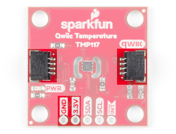 | Image may be NSFW. Clik here to view. 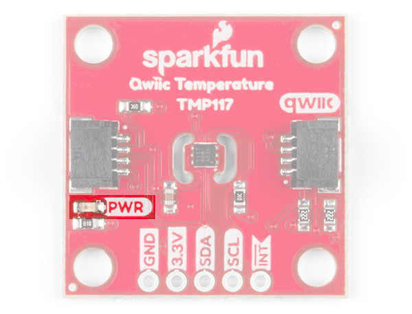 |
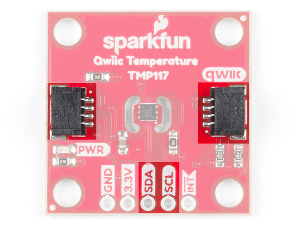
I2C Pins
To communicate with the sensor, you will need an I2C bus. The Qwiic system makes it easy to connect the TMP117 to your projects via the Qwiic connector. You can add a Qwiic cable between the sensor and development board to start experimenting with the sensor in your projects. Depending on your application, you can also connect to the I2C pins via the plated through holes for SDA and SCL.
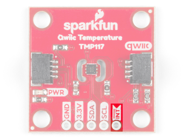
Interrupt Pin (a.k.a. Alert Pin)
The INT pin on the board is connected to the TMP117's "alert" pin. When the pin is active, it will be pulled LOW by default. If the TMP117's temperature limits are configured and the sensor exceeds the values, the alert pin will pulled LOW.
Jumpers
The board has a few jumper pads on the board. If you have not worked with jumper pads, make sure to check out the tutorial on "How to Work with Jumper Pads and PCB Traces" for more information.
How to Work with Jumper Pads and PCB Traces
April 2, 2018
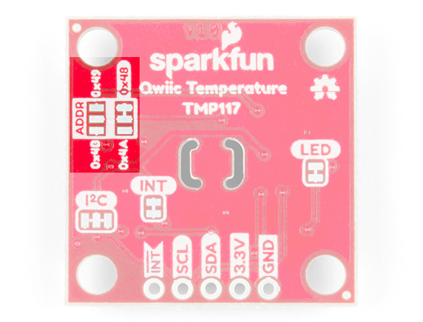
Address Select
The default address of the board is 0x48. If you need to adjust the address of the sensor, you can cut the trace connecting to the default address and add a solder jumper to the respective pads to change the address to 0x49, 0x4A, or 0x4B.
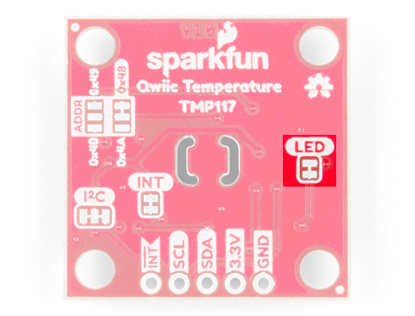
LED
If you need to disable the PWR LED to make the board inconspicuous, conserve more power, or ensure that you are minimizing any heat generated from the LED, you can cut the jumper connecting to the LED.
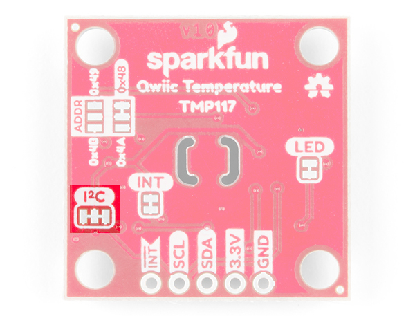
Pull-Up Resistors
The board also includes jumpers to disable the pull-up resistors on the I2C bus line. If you are using a few I2C devices on the same bus that already have pull-up resistors on their respective boards, you may want to cut the jumpers to disconnect. This is for special use cases when daisy chaining about 7x I2C devices on the same bus. Keep in mind that you will want to avoid heavy bypass traffic on the I2C bus if you are trying to take accurate readings.
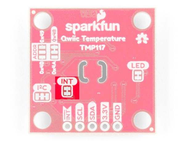
There is also a pull-up resistor on the INT pin if you need to disable the it as well.
Dimensions
The board uses the standard Qwiic 1.0"x1.0" board size with four mounting holes.

Hardware Hookup
This board is an I2C based board and so we've included a Qwiic connector on the breakout board. Hooking the sensor up is easy. Just plug one end of the Qwiic cable into the Qwiic TMP117 and the other to your development board. In this case, it's the RedBoard Qwiic. You'll be ready to upload a sketch and start reading temperature values. It seems like it's too easy too use, but that's why we made it that way!

If you need to temporarily access the pins via the standard breadboard spaced 0.1" PTH pads, you can connect some IC hooks to the through holes. In the image below, the interrupt pin needed to be measured with a multimeter so two IC hooks were connected to the board as a temporary connection. For a secure connection, you'll need to solder headers to the PTH pads.

Arduino Library
SparkFun has written a library to control the Qwiic TMP117. You can obtain these libraries through the Arduino Library Manager. By searching for TMP117, you will get two results. Click on the one written by SparkFun Electronics and you should be able to install the latest version. If you prefer downloading the libraries manually you can grab them from the GitHub repository:
Arduino Example Code
Basic Readings Example1_BasicReadings.ino
This example prints out the temperature in degrees Celsius and Fahrenheit. Te beginning of the code is pretty much the same for the examples. The code initializes the I2C bus and serial UART to pass the data to our Arduino serial monitor. We'll want to set the bus to fast mode as recommended by the datasheet. Once initialized, we'll check to see if the address matches the TMP117. By default, this is 0x48. If it matches, we'll continue running the sketch.
This particular example will check to see if the TMP117 measured and averaged the temperature readings. If there is data ready, the TMP117 will notify us from the configuration register. When ready, we'll read the temperature registers and output it out to the Arduino serial monitor.
If you have already, open the example up. Select your board and COM port. Hit the upload button. Open the serial monitor at 115200 baud to begin seeing the output. Try heating the sensor with your finger or lightly breathe some air across the sensor to watch the temperature values change!

Alert Status Example2_AlertStatuses.ino
This example configures the serial I2C and UART like the first example. We'll set alert function mode and temperature limits. When ready, we'll check to see if the temperature exceeds the high or low limits. By default, the alert function mode is set to alert mode. We set it again just in case. If we above the high limit, the high alert flag will be raised and we will output high alert.. If we are below the low limit, the high alert flag will be raised and we will output the low alert. Otherwise, we will have message indicating that there is no alert.
Set Offset Temperature Example3_SetOffsetTemperatureValue.ino
In this example, you can adjust the offset temperature of the TMP117. This is useful if you need to adjust the temperature readings based on your system in case the location you are measuring is warmer or colder than the surrounding environment.
Set Conversion Mode Example4_SetConversionMode.ino
You can change the continuous conversion mode to either one-shot or shutdown mode for low power applications. In one-shot mode, the TMP117 will take one temperature reading. After one temperature reading, the sensor will enter low power shutdown mode. When the TMP117 is set to shutdown mode, all temperature conversions are aborted and the TMP117 will enter low power shutdown mode.
Set Conversion Cycle Time Example6_SetConversionCycleTime.ino
In this example, you can adjust the conversion cycle bit and the conversion averaging mode. By adjusting these values, you can reduce the amount of noise to provide stable temperature readings. You'll want to adjust these based on your application.
More Examples
There's a few more examples in the library. Make sure to read through the description and comments in the code before trying out the additional examples that were not explained earlier!
Resources and Going Further
Now that you've successfully got your Qwiic TMP117 up and running, it's time to incorporate it into your own project! For more information, check out the resources below:
- Schematic (PDF)
- Eagle Files (ZIP)
- Board Dimensions (PNG)
- Datasheet (PDF)
- Arduino Library
- GitHub Product Repo
- SFE Product Showcase
Need some inspiration for your next project? Check out some of these related tutorials using temperature sensors:
MAX31855K Thermocouple Breakout Hookup Guide
LilyPad Temperature Sensor Hookup Guide
TMP102 Digital Temperature Sensor Hookup Guide
SparkFun Inventor's Kit Experiment Guide - v4.1
learn.sparkfun.com | CC BY-SA 3.0 | SparkFun Electronics | Niwot, Colorado