RED-V Thing Plus Hookup Guide a learn.sparkfun.com tutorial
Available online at: http://sfe.io/t1099
Introduction
SparkFun is pleased to welcome its a whole new instruction set architecture (ISA) to its family, the RISC-V ISA (pronounced “risk-five”), and along with it, introduce the RED-V Thing Plus (pronounced “red-five”). In this tutorial, we'll be focusing on the hardware.

What sets the RISC-V ISA from the rest is that it is completely open-source; including the instruction set architecture (ISA). That means anyone can make full use the microcontroller without requiring royalties, licenses, or non-disclosure agreements (NDAs). The RED-V comes in the familiar SparkFun Thing Plus form factor and includes the SiFive Freedom E310 core, 32MB of QSPI flash, an NXP K22 ARM Cortex-M4 for USB connectivity and operating as a JTAG interface, and a Qwiic connector.
Required Materials
To follow along with this tutorial, you will need the following materials and software. You may not need everything though depending on what you have. Add it to your cart, read through the guide, and adjust the cart as necessary. Here is what you would need to get started:
Hardware
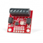
- RED-V Thing Plus - You'll definitely need this; otherwise, you are probably on the wrong tutorial page (wink).
- USB 3.1 Cable A to C - 3 Foot - The USB interface serves two purposes: it powers the board and allows you to upload programs to it. (You might even have a few of these in you drawer!)
You Will Also Need
To utilize all the features of the development board, you may need the following accessories.
Jumper ModificationHeaders & AccessoriesARM Programmers
wish to perform. Feel free to modify the items in your cart to fit your needs.
Jumper Modification
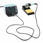
If you would like to modify the 3.3V/5V I/O jumper or A4/A5 Qwiic connector jumpers, you will need soldering equipment and/or a knife.


Qwiic Example
If you would like to follow along with the examples below to interact with the physical world, you will also need the following items:

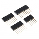
Headers & Accessories
If you would like to add headers to your board, check out some of the following items:


Below is a sample selection of our other headers and soldering tools in our catalog. For a full selection of our available Headers or Soldering Tools, click on the associated link.


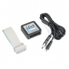
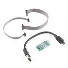
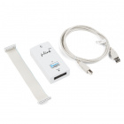
ARM Programmers
If you would like to debug or flash your ARM processor on your own, here are some of our ARM Programmers:

Suggested Reading
Before continuing on with this tutorial, you may want to familiarize yourself with some of these topics if they’re unfamiliar to you:
How to Solder: Through-Hole Soldering
One of the new, advanced features of the board is that it takes advantage of the Qwiic connect system. We recommend familiarizing yourself with the Logic Levels and I2C tutorials (above) before using it, as all Qwiic sensors utilize an I2C communication protocol. Click on the banner above to learn more about Qwiic products.
Hardware Overview
Power & Programming
There are a few different ways to power the SparkFun RED-V Thing Plus:
- USB-C
- JST connector (battery power)
- power pins broken out on the edge of the board
The easiest way (which will also allow you to program your board) is to simply plug it into your computer via USB-C. This will provide 5V to the board and will also allow you access to the super cool USB-to-JTAG interface for programming. Once you've programmed your RED-V however, you may want to have it running off of a different power supply. If you use a wall wart on the USB-C connector, make sure it outputs a regulated 5V DC. You can also use the black JST connector to provide battery power from a LiPo battery. There is an on-board LiPo charger with the current rate set to 500mA. Make sure to use LiPo batteries that have a capacity greater than 500mAh when charging. If you decide to power the board via the VUSB or VBAT pins, make sure to not exceed 6.5V since this is the absolute maximum for the 3.3V voltage regulator. Or you can power the board through the breakout pins on the edge of the board. If you are using 3V3 and GND, make sure that your voltage is regulated when applying power to the pin.

Always-On Core
The FE310 contains an Always-On (AON) block that allows easy power control of the FE310. It includes its own real-time clock and is also attached to the WAKE button on the board. This allows you to put the FE310 to sleep and wake it up upon a time-generated or user-generated interrupt.

Buttons
The RED-V has two buttons: a RESET button and a WAKE button. The RESET button is pretty self explanatory and is used to reset the FE310. A single tap of the RESET button will run the code loaded onto the FE310's QSPI flash. A quick double tap will put the FE310 into safe bootloader mode, which will allow you to flash new code to the RED-V if you've managed to really mess things up (i.e. Oops I put the core to sleep and forgot to add a way to wake it up). The pin is also broken out on the edge of the board. Adding a jumper wire from this pin to GND will reset the board as well.

The RED-V is also equipped with an Always-On or AON core (mentioned above) which can be programmed to shut down the main core of the FE310 and wake it up upon a button-generated or user-generated interrupt. The WAKE button can be configured in software to wake the FE310 from deep sleep.

Jumpers
The FE310 has a few jumpers as well, all of which are open by default. The two jumpers located next to the I2C label is for the I2C pull-up resistors. These resistors are not attached by default as there are I2C pull-up resistors on all SparkFun Qwiic slaves. If you're using a 3rd party board, you may need to close these jumper by the Qwiic connector to attach the pull-ups to the I2C bus. The jumper by the USB-C connector (next to the Segger logo) is for bypassing the 0.5A PTC fuse. This is for special cases where you need a lot current. If you need to connect the NC pin to GND, you can also add a solder jumper on the pads as well. Most of the time, you can leave the bypass and NC jumpers open.

Dimensions
The RED-V Thing Plus measures at 2.3"x0.90".

Resources and Going Further
Now that you've successfully got started with your SAMD51 Thing Plus, it's time to incorporate it into your own project! For more information, check out the resources below:
- Schematic (PDF)
- Eagle Files (ZIP)
- Dimensions
- FE310-G002 Datasheet (PDF)
- Qwiic Landing Page
- RISC-V
- SiFive
- e31 Core
- Datasheets and Manuals
- Freedom Studio and E SDK
- Freedom Studio User Manual
- GitHub Hardware Repo
- SFE Product Showcase
learn.sparkfun.com | CC BY-SA 3.0 | SparkFun Electronics | Niwot, Colorado