Pro Micro RP2040 Hookup Guide a learn.sparkfun.com tutorial
Available online at: http://sfe.io/t1560
Introduction
The Pro Micro RP2040 is a low-cost, high-performance board with flexible digital interfaces featuring the Raspberry Pi Foundation's RP2040 microcontroller. The board uses well known Pro Micro footprint with castellated mounting holes.

Required Materials
To follow along with this tutorial, you will need the following materials. You may not need everything though depending on what you have. Add it to your cart, read through the guide, and adjust the cart as necessary.


Tools
You will need a soldering iron, solder, and general soldering accessories for a secure connection when using the plated through hole pads.


Prototyping Accessories
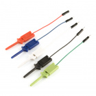
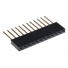
Depending on your setup, you may want to use IC hooks for a temporary connection. However, you will want to solder header pins to connect devices to the plated through holes for a secure connection.


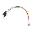
For those that want to take advantage of the Qwiic enabled devices, you'll want to grab a Qwiic cable.


Suggested Reading
If you aren't familiar with the Qwiic system, we recommend reading here for an overview if you decide to take advantage of the Qwiic connector.
| Qwiic Connect System |
We would also recommend taking a look at the following tutorials if you aren't familiar with them.
How to Solder: Through-Hole Soldering
Serial Communication
Serial Peripheral Interface (SPI)
Analog vs. Digital
Hardware Overview
Old School to New School
The Pro Micro RP2040 design uses the original Pro Micro and Qwiic Pro Micro USB C's footprint.
 |  |
| Older Pro Micro with ATmega32U4 | Newer Qwiic Pro Micro USB C with RP2040 |
The Pinout
All of the Pro Micro RP2040's GPIO and power pins are broken out to two, parallel headers. Some pins are for power input or output, other pins are dedicated GPIO pins. Further, the GPIO pins can have special function depending on how they are multiplexed Here's a map of which pin is where and what special hardware functions it may have.
Power
There are a variety of power and power-related nets broken out to connectors and through hole pads. Each pad has a castellated edge. THe back of the board also has the USB pins broken out for power

These nets consist of the following:
- V is the voltage provided from the USB connector.
- + is the raw, unregulated voltage input for the Pro Micro RP2040. If the board is powered via USB (i.e. V), the voltage at this pin will be about 4.8V (USB's 5V minus a Schottky diode drop). On the other hand, if the board is powered externally, through this pin, the applied voltage can be up to 5.3V.
- 3.3V is the voltage supplied to the on-board RP2040. We suggest using regulated 3.3V when connecting to this pin. If the board is powered through the raw "+" pin, this pin can be used as an output to supply 3.3V other devices.
- RST can be used to restart the Pro Micro RP2040. There is a built-in reset button to reset the board. However, the pin is broken out if you need to access this pin externally. This pin is pulled high by a 10kΩ resistor on the board, and is active-low, so it must be connected to ground to initiate a reset. The Qwiic Pro Micro will remain "off" until the reset line is pulled back to high.
- GND, of course, is the common, ground voltage (0V reference) for the system.
GPIO Pins
THe Pro Micro RP2040 breaks out the GPIO pins to plated through holes pads on the edge of the board. Each pad is castellated as well. On the back, there are additional pads to connect to the USB data and SWD programming pins.

The Pro Micro's GPIO pins — 18 in all — are multi-talented. Every pin can be used as a digital input or output, for blinking LEDs or reading button presses. These pins are referenced via an integer value between 0 and 29.
Four pins feature analog to digital converters (ADCs) and can be used as analog inputs. These are useful for reading potentiometers or other analog devices.
All pins can be set with the pulse width modulation (PWM) functionality, which allows for a form of analog output. The RP2040 can only provide a total of up to 16 controllable PWM outputs.
There are hardware UART (serial), I2C, and SPI pins available as well. These can be used to interface with digital devices like serial LCDs, XBees, IMUs, and other serial sensors.
The RP2040 has 26 external interrupts, which allow you to instantly trigger a function when a pin goes either high, low, or changes state.
Qwiic Connector
The board includes a Qwiic connector to easily connect Qwiic enabled I2C devices to the board.

On-Board LEDs.
There are two LEDs on the Pro Micro RP2040. The red LED indicates whether power is present. The other is the addressable WS2812 RGB LED. The addressable LED is connected to GPIO25. You'll need a WS2812 library to control that LED..

External Flash Memory
The Pro Micro RP2040 includes a W25Q128JVPIM, which adds 128Mb (16MB) of flash memory externally.

Boot Button
The boot button is connected to the external flash memory. Pressing this button forces USB boot mode so that the board shows up as a USB mass storage device.

Reset Button
As explained earlier, there is a reset button to reset the RP2040. This adds the option of forcing the RP2040 into bootloader mode without needing to unplug/replug the board back into your USB port. To keep the board size at a minimum, the buttons are not labeled. To distinguish between the two buttons, just remember that the reset button is on the same side of the board as the reset pin.

Board Dimensions
The board measures 1.3" x 0.7". Keep in mind that the USB-C connector is not flush with the board and will protude about 0.05" from the edge of the board. Not included in the image below is the PCB thickness, which is 0.8mm. This is thinner than a majority of PCBs used for SparkFun original designs.

Hardware Hookup
Header pins were left off the Pro Micro RP2040 to allow users the flexibility of connecting any type of 0.1" header to the board. For temporary connections to the I/O pins, you could use IC hooks to test out the pins. However, you'll need to solder headers or wires of your choice to the board for a secure connection. For advanced users, you could also design a PCB to take advantage of the castellated edges for a lower profile. Here are a few tutorials to connect to the pads depending on your personal preference.
How to Solder: Through-Hole Soldering
September 19, 2013
How to Solder: Castellated Mounting Holes
May 12, 2015
In order to power and upload to the board, you will simply need a USB C cable connected to your computer.
Software
There are two methods of programming the RP2040. You can use MicroPython or C/C++ depending your personal preference. Stay tuned for more information!
Resources and Going Further
For more information, check out the resources below:
learn.sparkfun.com | CC BY-SA 3.0 | SparkFun Electronics | Niwot, Colorado