Qwiic Haptic Driver DA7280 a learn.sparkfun.com tutorial
Available online at: http://sfe.io/t1461
Introduction
The Qwiic Haptic Driver includes an itty-bitty, Linear Resonant Actuator (LRA) vibration motor and Dialog Semiconductor's DA7280 motor driver IC for applications that require haptic feedback. There is also a kit for those that would like the motor mounted separately from the board. Note that you will need to manually solder the wires and motor to the board.


Required Materials
To follow along with this tutorial, you will need the following materials. You may not need everything though depending on what you have. Add it to your cart, read through the guide, and adjust the cart as necessary.


Suggested Reading
If you aren't familiar with the Qwiic system, we recommend reading here for an overview .
 |
| Qwiic Connect System |
If you aren’t familiar with the following concepts, we also recommend checking out a few of these tutorials before continuing. While the Haptic Motor Driver hookup guide linked below uses a different IC on the board, there is some useful information about different motors available in the tutorial.
Hardware Overview
Power and Logic Levels
We recommend powering the board through the Qwiic connector when quickly prototyping. For a more secure connection, you can always solder to the PTH pads labeled 3V3/VDD and GND. The recommended input voltage when using the board with a microcontroller is 3.3V. However, you could potentially power the board between 2.8V to 5.5V as explained in the datasheet. Note that the 3V3/VDD is connected to VDDIO. There is a jumper on the back of the board to disconnect the input voltage and the logic levels if you decide to use different voltages. If you decide to adjust the logic level, this is typically 1.8V. However, you can set the logic levels between 1.35V and 5.5V as long as VDDIO≤ VDD and if GPI0, GPI1, and GPI2 are not grounded as it is recommended in the datasheet.
I2C
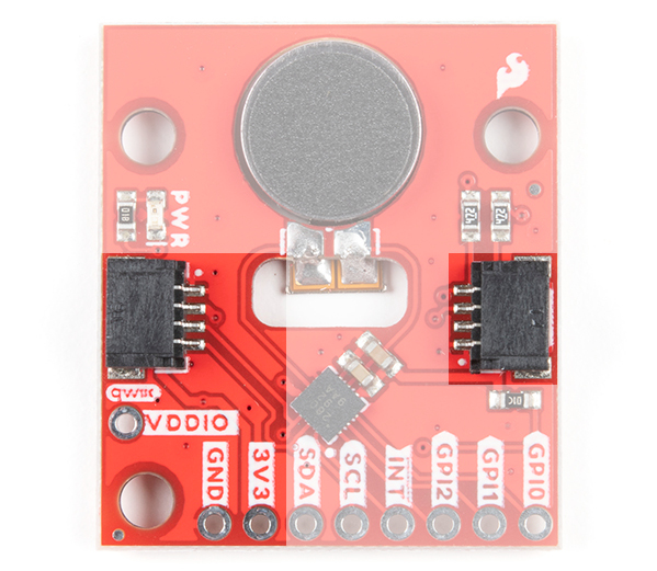
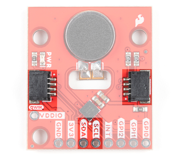
The main method of controlling the DA7280 and the vibe motor is through the I2C bus. The board includes two Qwiic connectors for fast prototyping and removes the need for soldering. All you need to do is plug a Qwiic cable into the Qwiic connector and voila! You can also solder to the PTHs labeled as SDA and SCL as an alternative. The address for the DA7280 is 0x4A.
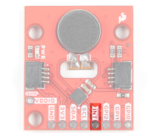
Interrupt
The interrupt is active low and notifies the host microcontroller when the DA7280 has finished driving the motor. This connection is optional and available for those that decide to include an interrupt for their application.
PWM Pin
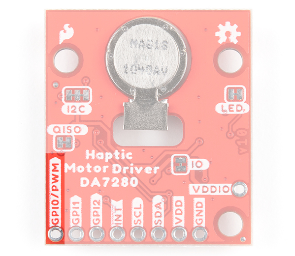
The second method of controlling the DA7280 is to send a PWM signal to the GPI0 pin. Once the DA7280 is configured to PWM mode via I2C, the duty cycle of the PWM signal will be reflected on the DA7280's output drive to the vibration motor. The DA7280 requires that the PWM signal is at least 10kHz. The top of the board only labels the PTH as GPI0 due to the space available around the pin while the back of the board labels the pin as GPI0/PWM.
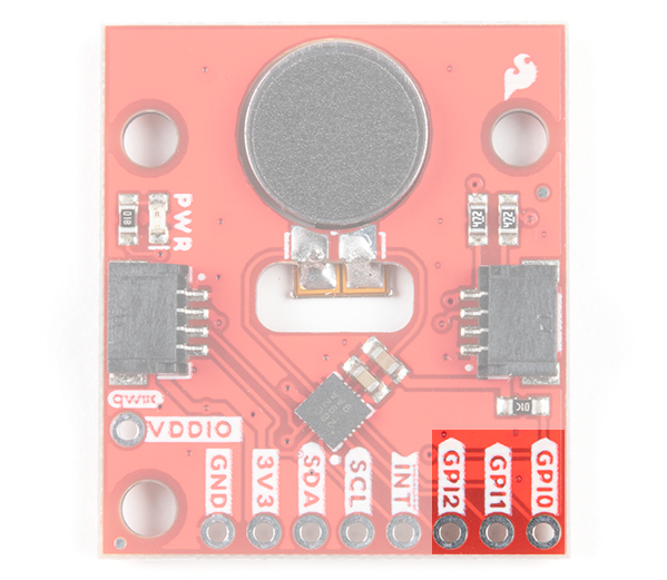
GPI Pins
The third method of controlling DA7280 and the motor is through the general purpose input (GPI) pins. These can be configured to edge trigger based on the the combination of the pins and waveforms that are stored in the DA7280's memory.
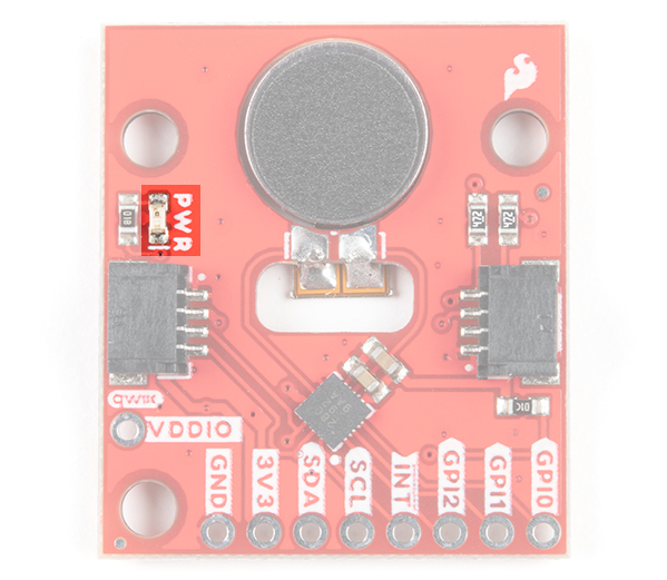
LED
The board includes an LED indicator that lights up when there is power available.
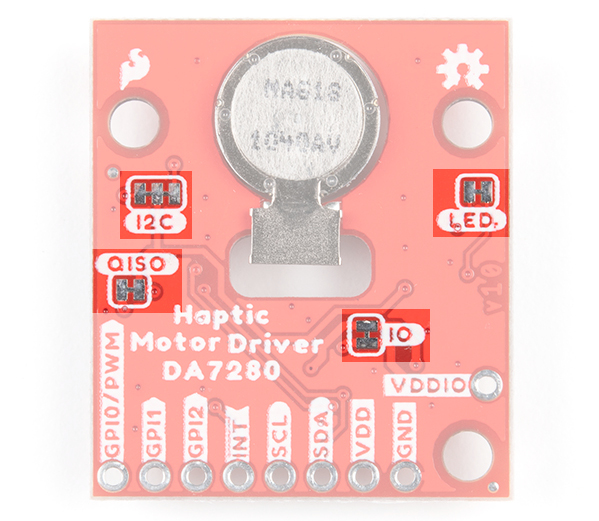
Jumpers
There are four jumpers on the back of the board. For more information, check out our tutorial on working with jumper pads and PCB traces should you decide to cut the traces with a hobby knife.
- LED - This is connected to the PWR LED on the top of the board. Cutting this disables the LED.
- I2C - The I2C jumper is connected to the 4.7kΩ pull-up resistors for the I2C bus. Most of the time you can leave these alone unless your project requires you to disconnect the pull-up resistors.
- QISO - The QISO jumper is connected to the Qwiic bus power line (i.e. 3.3V). Cut this trace to separate power from the Qwiic ports if you decide to power the board with a different voltage on 3V3/VDD. Note that the I2C lines are still pulled up to 3.3V.
- IO - The IO jumper connects 3.3V/VDD to VDDIO for the DA7280. Cut this trace and supply VDDIO with a different voltage to adjust the DA7280's logic levels. This is typically 1.8V. However, you can set the logic levels between 1.35V and 5.5V as long as VDDIO≤ VDD and if GPI0, GPI1, and GPI2 are not grounded as it is recommended in the datasheet
Board Dimensions
The board dimension is 1.00" x 1.15" and includes 3x mounting holes. The mounting holes are spaced using the Qwiic standard for 1.0"x1.0" sized boards. Note that the board is longer on one side to accommodate the SMD vibe motor.

Hardware Assembly
There are three modes (I2C, PWM, and stande-alone with the GPI) available for the DA7280. For the scope of this tutorial and Arduino Library, we will be using the I2C and PWM modes. If you are using the PTHs, we recommend soldering header pins or wires to the board for a secure connection.
I2C Mode
The main method to control the DA7280 is through an I2C bus. You'll need the RedBoard Qwiic and a USB cable to program the microcontroller. Insert the USB cable into the RedBoard. Then insert a Qwiic cable between the RedBoard Qwiic and Qwiic Haptic Driver. Depending on your application, you can also solder to the plated through holes for a secure connection.

PWM Mode
The second method of controlling the DA7280 is via PWM. The Haptic Driver IC requires that the PWM signal frequency given to GPI0/PWM pin is at least 10kHz. The default PWM methods of analogWrite() does not provide a method of controlling the frequency of the PWM signal. To use with the RedBoard with ATmega328P, you will need to use the TimerOne Arduino Library by Paul Stoffregen as explained later in this tutorial. Note that this library is limited to certain boards. For the Arduino Uno (e.g. the RedBoard with ATmega328P) the pins that are reserved for PWM are on pins 9 and 10.
In this case, we will connect the Qwiic Haptic's GPIO0/PWM pin to the RedBoard's pin 9. We also still need to control the DA7280. Make sure to include a Qwiic cable between the boards as well.

Arduino Library
The SparkFun DA7280 Haptic Driver Arduino library can be downloaded with the Arduino library manager by searching 'SparkFun Qwiic Haptic Driver DA7280' or you can manually install the library by downloading the zip here from the GitHub repository:
Example 1: I2C Mode
We're just going to look the I2C_Mode.ino example. Open the File>Examples>SparkFun Haptic Driver Arduino Library>I2C_Mode. Select your board (in this case Arduino Uno) and COM port. Then hit the upload button.
Once uploaded, the Qwiic Haptic Driver should begin vibrating every half a second. Note that the value for hapDrive.setVibrate() range from 0 to 127. A value of 0 turns the motor off while a value of 127 turns the motor fully on. Try adjusting the value to
hapDrive.enableFreqTrack(false);. Restricting the PCB (e.g. squeezing) raises an error which stops operation because it can not reach resonance.
Example 2: PWM Mode
GPI0/PWM pin is at least 10kHz. The default PWM methods of analogWrite() does not provide a method of controlling the frequency of the PWM signal. To use with the RedBoard with ATmega328P, you will need to use the TimerOne Arduino Library by Paul Stoffregen. Note that this library is limited to certain boards. For the Arduino Uno (e.g. the RedBoard with ATmega328P) the PWM pins that are reserved are on pins 9 and 10.
Since the library version is not included in the Arduino Library Manager, you will need to manually install the TimerOne library by Paul Stoffregen by downloading it from the GitHub repository. In the Arduino IDE's menu, navigate to Sketch>Include Library>Add .ZIP Library.... A window will open up requesting for the ZIP file to be included. Head to the Downloads folder where the TimerOne-master.zip is saved.
We're just going to look the PWM_Mode_Timer1.ino example. Open the File>Examples>SparkFun Haptic Driver Arduino Library>PWM_Mode_Timer1.ino. Select your board (in this case Arduino Uno) and COM port. Then hit the upload button.
Once uploaded, the Qwiic Haptic Driver will first clear a flag that shuts the motor off if the PWM signal is cut off suddenly without being set into inactive mode. The motor will begin vibrating based on the PWM signal in the for loop. In this case, the PWM signal is dependent on the value for power and we slowly increase the intensity.
You will need to install the Teensyduino for Teensy or the board definitions for the Artemis if you decide to use the example. Once installed, make sure to select your board and COM port before uploading the example.
Resources and Going Further
For more information about the Qwiic Haptic Driver DA7280, check out the resources below.
- Schematic (PDF)
- Eagle Files (ZIP)
- Board Dimensions (PNG)
- Datasheet
- GitHub
- Arduino Library
- TimerOne by Paul Stoffregen - This library is required if you are using PWM Mode on the RedBoard with ATmega328P.
- DA7280 Haptic Driver
- Hardware Repo
- Arduino Library
Looking for more information about haptic motors project ideas? Check out the following tutorials.
LilyPad Vibe Board Hookup Guide
learn.sparkfun.com | CC BY-SA 3.0 | SparkFun Electronics | Niwot, Colorado