SparkFun RTK Express Hookup Guide a learn.sparkfun.com tutorial
Available online at: http://sfe.io/t1857
Introduction
The RTK Express from SparkFun is your one stop shop for high precision geolocation and surveying needs. For basic users, it’s incredibly easy to get up and running and for advanced users, the RTK Express is a flexible and powerful tool.

With just a few minutes of setup, the RTK Express is one of the fastest ways to take centimeter grade measurements.

By connecting your phone to the RTK Express over Bluetooth, your phone can act as the radio link to provide correction data as well as receive the NMEA output from the device. It’s how $10,000 surveying devices have been operating for the past decade - we just made it easier, smaller, and a lot cheaper.
Required Materials
While the RTK Express is nicely enclosed you will need a few cables and antennas to make everything work. We'll go into the specifics of how to hook things together but in general you will need to get a good quality L1/L2 antenna:
Depending on your setup you may want to use your phone for RTCM correction data. If a source is not available online, you will need a 2nd RTK Express setup in base mode and a radio link connecting the Base to the Rover. Again, we'll go into details but we designed RTK Express to work with these 500mW 915MHz telemetry radios out of the box:

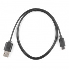
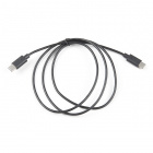
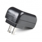
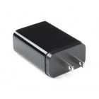
To charge the RTK Express you will need a USB C cable and a power supply. SparkFun carries a few options:
Suggested Reading
GNSS RTK is an incredible feat of engineering that has been made easy to use by powerful GNSS receivers such as the ZED-F9P by u-blox (the receiver inside RTK Express). The process of setting up an RTK system will be covered in this tutorial but if you want to know more about RTK here are some good tutorials to brush up on:
What is GPS RTK?
Getting Started with U-Center for u-blox
GPS-RTK2 Hookup Guide
Setting up a Rover Base RTK System
How to Build a DIY GNSS Reference Station
Hardware Overview
The RTK Express is a fully enclosed, preprogrammed device. There are very few things to worry about or configure but we will cover the basics.
Buttons
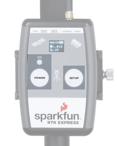
The RTK Express uses two buttons, Power and Setup for in-field configuration.
Setup
This device can be used in four modes:
- GNSS Positioning (~30cm accuracy) - also known as 'Rover'
- GNSS Positioning with RTK (1.4cm accuracy) - also known as 'Rover with RTK Fix'
- GNSS Base Station
- GNSS Base Station NTRIP Server
At power on the device will enter Rover or Base mode; whichever state the device was in at the last power down. When the SETUP button is pressed the RTK Express will toggle between Rover and Base mode. The display will indicate the change with a small car or flag icon.
In Rover mode the RTK Express will receive L1 and L2 GNSS signals from the four constellations (GPS, GLONASS, Galileo, and BeiDou) and calculate the position based on these signals. Similar to a standard grade GPS receiver, the RTK Express will output industry standard NMEA sentences at 4Hz and broadcast them over any paired Bluetooth device. The end user will need to parse the NMEA sentences using commonly available mobile apps, GIS products, or embedded devices (there are many open source libraries). Unlike standard grade GPS receivers that have 2500m accuracy, the accuracy in this mode is approximately 300mm horizontal positional accuracy with a good grade L1/L2 antenna.
When the device is in Rover mode and RTCM correction data is sent into the radio port or over Bluetooth, the device will automatically enter Positioning with RTK mode. In this mode RTK Express will receive L1/L2 signals from the antenna and correction data from a base station. The receiver will quickly (within a few seconds) obtain RTK float, then fix. The NMEA sentences will have increased accuracy of 14mm horizontal and 10mm vertical accuracy. The RTCM correction data can be obtained from a cellular link to online correction sources or over a radio link to a 2nd RTK Express setup as a base station.
In Base mode the device will enter Base Station mode. This is used when the device is mounted to a fixed position (like a tripod or roof). The RTK Express will initiate a survey. After 60 to 120 seconds the survey will complete and the RTK Express will begin transmitting RTCM correction data out the radio port. A base is often used in conjunction with a second RTK Express (or RTK Surveyor) unit set to 'Rover' to obtain the 14mm accuracy. Said differently, the Base sits still and sends correction data to the Rover so that the Rover can output a really accurate position. You’ll create an RTK system without any other setup.
Power
The Power button turns on and off the unit. Press and hold the power button until the display illuminates. Press and hold the power button at any time to turn the unit off. The RTK Express has a built-in 1300mAh lithium polymer battery that will enable over 5 hours of field use between charging. If more time is needed a common USB power bank can be attached boosting the field time to 40 hours.
Charge LED
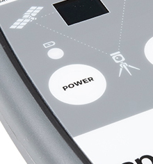
The Charge LED is located above the Power button. It will illuminate any time there is an external power source and will turn off when the internal battery is charged. With the unit fully powered down, charging takes approximately 1.5 hours from a 1A wall supply or 3 hours from a standard USB port. The RTK Express can run while being charged but it increases the charge time. Using an external USB battery bank to run the device for extended periods or running the device on a permanent wall power source is supported.
Connectors
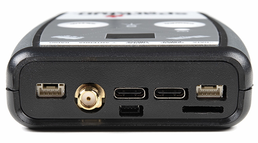
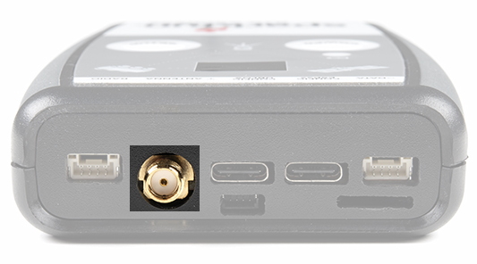
Antenna:
This SMA connector is used to connect an L1/L2 type GNSS antenna to the RTK Express. Please realize that a standard GPS antenna does not receive the L2 band signals and will greatly impede the performance of the RTK Express (RTK fixes are nearly impossible). Be sure to use a proper L1/L2 antenna.
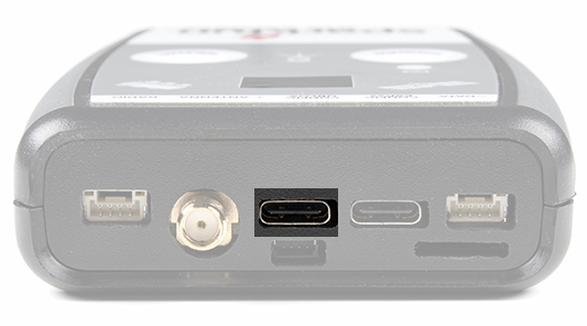
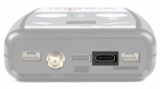
Configure u-blox:
This USB C connector is used for charging the device and/or directly configuring and inspecting the ZED-F9P GNSS receiver using u-center. It’s not necessary in normal operation but is handy for tailoring the receiver to specific applications. As an added perk, the ZED-F9P can be detected automatically by some mobile phones and tablets. If desired, the receiver can be directly connected to a compatible phone or tablet removing the need for a Bluetooth connection.
Configure ESP32:
This USB C connector is used for charging the device, configuring the device, and reprogramming the ESP32. Various debug messages are printed to this port at 115200bps and a serial menu can be opened to configure advanced settings.
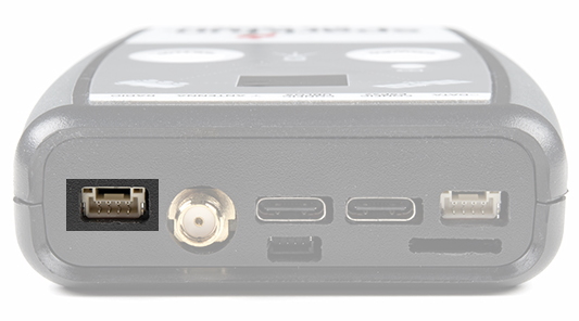
Radio:
This 4-pin JST connector is used to allow RTCM correction data to flow into the device when it is acting as a rover or out of the device when it is acting as a base. The connector is a 4-pin locking 1.25mm JST SMD connector (part#: SM04B-GHS-TB, mating connector part#: GHR-04V-S). The RTK Express comes with a cable to interface to this connector but additional cables can be purchased. You will most likely connect this port to one of our Serial Telemetry Radios if you don’t have access to a correction source on the internet. The pinout is 3.5-5.5V / TX / RX / GND. 3.5V to 5.5V is provided by this connector to power a radio with a voltage that depends on the power source. If USB is connected to the RTK Express then voltage on this port will be 5V (+/-10%). If running off of the internal battery then voltage on this port will vary with the battery voltage (3.5V to 4.2V depending on the state of charge). While the port is capable of sourcing up to 2 amps, we do not recommend more than 500mA. This port should not be connected to a power source.
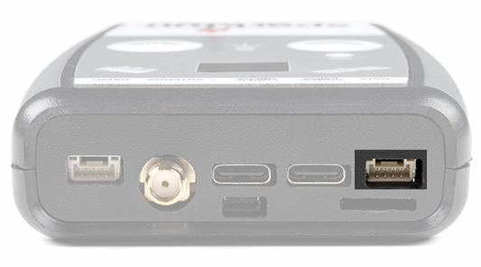
Data:
This 4-pin JST connector is used to output and input a variety of data to the RTK Express. The connector is a 4-pin locking 1.25mm JST SMD connector (part#: SM04B-GHS-TB, mating connector part#: GHR-04V-S). The RTK Express comes with a cable to interface to this connector but additional cables can be purchased.
Internally the Data connector is connected to a digital mux allowing one of four software selectable setups:
- NMEA - The TX pin outputs any enabled messages (NMEA, UBX, and RTCM) at a default of 460,800bps (configurable 9600 to 921600bps). The RX pin can receive RTCM for RTK and can also receive UBX configuration commands if desired.
- PPS/Trigger - The TX pin outputs the pulse-per-second signal that is accurate to 30ns RMS. The RX pin is connected to the EXTINT pin on the ZED-F9P allowing for events to be measured with incredibly accurate nano-second resolution. Useful for things like audio triangulation. See the Timemark section of the ZED-F9P integration for more information.
- I2C - The TX pin operates as SCL, RX pin as SDA on the I2C bus. This allows additional sensors to be connected to the I2C bus.
- GPIO - The TX pin operates as a DAC capable GPIO on the ESP32. The RX pin operates as a ADC capable input on the ESP32. This is useful for custom applications.
Most applications do not need to utilize this port and will send the NMEA position data over Bluetooth. This port can be useful for sending position data to an embedded microcontroller or single board computer. The pinout is 3.3V / TX / RX / GND. 3.3V is provided by this connector to power a remote device if needed. While the port is capable of sourcing up to 600mA, we do not recommend more than 300mA. This port should not be connected to a power source.
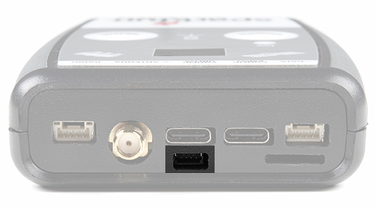
microSD:
This slot accepts standard microSD cards up to 32GB formatted for FAT16 or FAT32. Logging any of 67 messages at up to 4Hz is supported for all constellations.

The following 67 messages are supported for logging:
- NMEA-DTM
- NMEA-GBS
- NMEA-GGA
- NMEA-GLL
- NMEA-GNS
- NMEA-GRS
- NMEA-GSA
- NMEA-GST
- NMEA-GSV
- NMEA-RMC
- NMEA-VLW
- NMEA-VTG
- NMEA-ZDA
- NAV-CLOCK
- NAV-DOP
- NAV-EOE
- NAV-GEOFENCE
- NAV-HPPOSECEF
- NAV-HPPOSLLH
- NAV-ODO
- NAV-ORB
- NAV-POSECEF
- NAV-POSLLH
- NAV-PVT
- NAV-RELPOSNED
- NAV-SAT
- NAV-SIG
- NAV-STATUS
- NAV-SVIN
- NAV-TIMEBDS
- NAV-TIMEGAL
- NAV-TIMEGLO
- NAV-TIMEGPS
- NAV-TIMELS
- NAV-TIMEUTC
- NAV-VELECEF
- NAV-VELNED
- RXM-MEASX
- RXM-RAWX
- RXM-RLM
- RXM-RTCM
- RXM-SFRBX
- MON-COMMS
- MON-HW2
- MON-HW3
- MON-HW
- MON-IO
- MON-MSGPP
- MON-RF
- MON-RXBUF
- MON-RXR
- MON-TXBUF
- TIM-TM2
- TIM-TP
- TIM-VRFY
- RTCM3x-1005
- RTCM3x-1074
- RTCM3x-1077
- RTCM3x-1084
- RTCM3x-1087
- RTCM3x-1094
- RTCM3x-1097
- RTCM3x-1124
- RTCM3x-1127
- RTCM3x-1230
- RTCM3x-4072-0
- RTCM3x-4072-1
Qwiic:
This 4-pin Qwiic connector exposes the I2C bus of the ESP32 WROOM module. Currently, there is no firmware support for adding I2C devices to the RTK Express but support may be added in the future.
Power
The RTK Express has a built in 1300mAh battery and consumes approximately 240mA worst case with Bluetooth connection active, GNSS fully tracking, and a 500mW radio broadcasting. This will allow for around 5.5 hours of use in the field. If more time is needed in the field a standard USB power bank can be attached. If a 10,000mAh bank is attached one can estimate 30 hours of run time assuming 25% is lost to efficiencies of the power bank and charge circuit within RTK Express.
The RTK Express can be charged from any USB port or adapter. The charge circuit is rated for 1000mA so USB 2.0 ports will charge at 500mA and USB 3.0+ ports will charge at 1A.
RTK Express Display showing two battery bars
To quickly view the state of charge, turn on the unit. The battery icon will indicate the following:
- 3 bars: >75% capacity remain
- 2 bars: >50% capacity remain
- 1 bar: >25% capacity remain
- 0 bars: <25% capacity remain
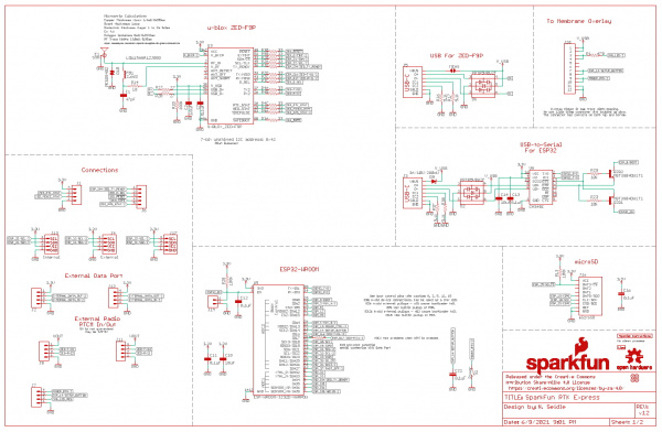
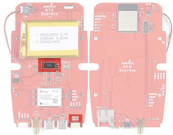
Hardware Overview - Advanced Features
The RTK Express is a hacker’s delight. Under the hood of the RTK Express is an ESP32 WROOM connected to a ZED-F9P as well as some peripheral hardware (LiPo fuel gauge, microSD, etc). It is programmed in Arduino and can be tailored by the end user to fit their needs.
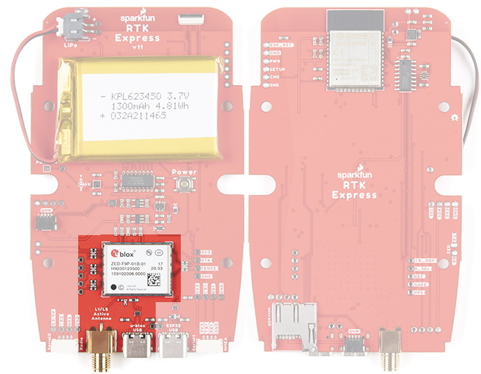
ZED-F9P GNSS Receiver
The ZED-F9P GNSS receiver is configured over I2C and uses two UARTs to output NMEA (UART1) and input/output RTCM (UART2). In general, the ESP32 harvests the data from the ZED-F9Ps UART1 for Bluetooth transmission and logging to SD.
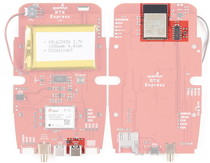
ESP32
The ESP32 uses a standard USB to serial conversion IC (CH340) to program the device. You can use the ESP32 core for Arduino or Espressif’s IoT Development Framework (IDF).
The CH340 automatically resets and puts the ESP32 into bootload mode as needed. However, the reset pin of the ESP32 is brought out to an external 2-pin 0.1” footprint if an external reset button is needed.
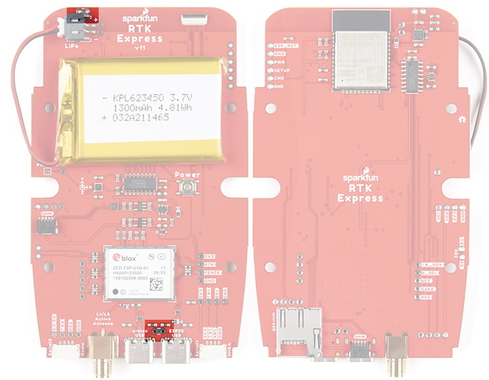
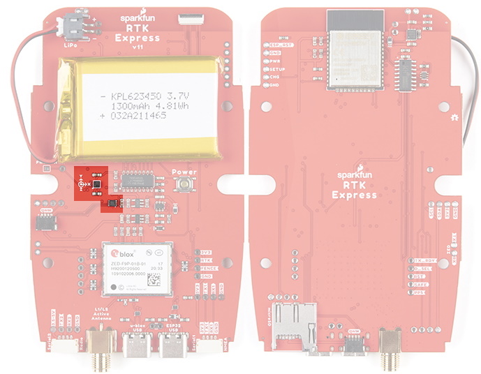
Measurement Jumpers
To facilitate the measurement of run, charge, and quiescent currents, two measurement jumpers are included. These are normally closed jumpers combined with a 2-pin 0.1” footprint. To take a measurement, cut the jumper and install a 2-pin header and use banana to IC hook cables to a DMM. These can then be closed with a 2-pin jumper.
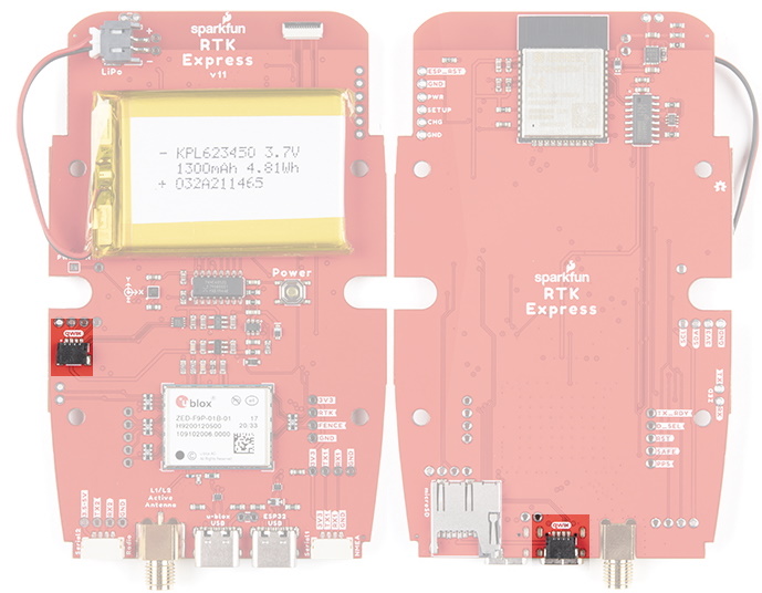
LiPo and Charging
The RTK Express houses a standard 1300mAh 3.7V LiPo. The charge circuit is set to 1A so with an appropriate power source, charging an empty battery should take a little over one hour. USB C on the RTK Express is configured for 2A draw so if the user attaches to a USB 3.0 port, the charge circuit should operate near the 1A max. If a user attaches to a USB 2.0 port, the charge circuit will operate at 500mA. This charge circuit also incorporates a 42C upper temperature cutoff to insure the LiPo cannot be charged in dangerous conditions.
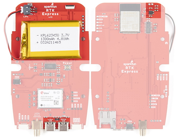
Fuel Gauge and Accelerometer
The MAX17048 is a simple to use fuel gauge IC that gives the user a statement of charge (SOC) that is basically a 0 to 100% report. The MAX17048 has a sophisticated algorithm to figure out what the SOC is based on cell voltage that is beyond the scope of this tutorial but for our purposes, allows us to reliably view the battery level when the unit is on.
The RTK Express also incorporates a the LIS2DH12 triple-axis accelerometer to aid in leveling in the field.
Qwiic
Two Qwiic connectors are included in the unit. The internal Qwiic connector connects to the OLED display attached to the upper lid. The lower Qwiic connector is exposed on the end of the unit. These allow connection to the I2C bus on the ESP32. Currently the stock RTK Express does not support any additional Qwiic sensors or display but users may add support for their own application.
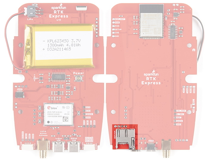
microSD
A microSD socket is situated on the ESP32 SPI bus. Any microSD up to 32GB is supported. RTK Express supports RAWX and NMEA logging to the SD card. Max logging time can also be set (default is 10 hours) to avoid multi-gigabyte text files. For more information about RAWX and doing PPP please see this tutorial.
Data Port and Digital Mux
The 74HC4052 analog mux controls which digital signals route to the external Data port. This allows a variety of custom end user applications. The most interesting of which is event logging. Because the ZED-F9P has microsecond accuracy of the incoming digital signal, custom firmware can be created to triangulate an event based on the receiver's position and the time delay between multiple captured events. Currently, TM2 event logging is supported.
Additionally, this mux can be configured to connect ESP pin 26 (DAC capable) and pin 39 (ADC capable) for end user custom applications.
Hardware Assembly
The RTK Express was designed to work with low-cost, off the shelf equipment. Here we’ll describe how to assemble a Rover and Base.
Rover
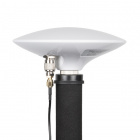
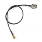
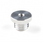
Shown here is the most common RTK Rover setup. A monopole designed for cameras is used. A cell phone holder is clamped to the monopod and the RTK Express is mounted. The ¼” camera thread of the monopole is adapted to ⅝” 11-TPI and a L1/L2 antenna is attached. A Male TNC to Male SMA cable connects the antenna to the RTK Express. No radio is needed because RTCM correction data is provided by a phone over Bluetooth.

If you’re shopping for a monopole (aka monopod), get one that is 65” in length or greater to ensure that the antenna will be above your head. We’ve had good luck with the Amazon Basics brand.
We have done lots of testing with the u-blox L1/L2 antenna and it's very good for the price and size. Mounted to a ground plate you will get good results. It's just a bit ungainly when mounted to the top of a monopole. We recommend the 'ufo' style L1/L2 antennas because they have a larger antenna element and a slightly larger ground plane than the u-blox antenna.

If you’re shopping for a cell phone clamp be sure to get one that is compatible with the diameter of your monopole and has a knob to increase clamp pressure. Our monopole is 27mm in diameter and we’ve had a good experience with this clamp and this clamp. Your mileage may vary.

If you are receiving RTCM correction data over a radio link it’s recommended that you attach a radio to the back of the RTK Express.

Picture hanging strips from 3M make a nice semi-permanent mount. Plug the 4-pin to 6-pin JST cable included with the RTK Express from the Radio port to either of the Serial Telemetry Radios (shipped in pairs). We really love these radios because they are paired out of the box, either can send or receive (so it doesn't matter which radio is attached to base or rover) and they have remarkable range. We achieved over a mile range (nearly 1.5 miles or 2.4km) with the 500mW radios and a big 915MHz antenna on the base (see this tutorial for more info).

Temporary Base
A temporary or mobile base setup is needed when you are in the field too far away from a correction source and/or cellular reception. A 2nd RTK Express is mounted to a tripod and it is configured to complete a survey-in (aka, locate itself), then begin broadcasting RTCM correction data. This data (~1000 bytes a second) is sent to the user's connected radio of choice. For our purposes, the 915MHz 500mW telemetry radios are used because they provide what is basically a serial cable between our base and rover.

Any tripod with a ¼” camera thread will work. The Amazon Basics tripod works well enough but is a bit light weight and rickety. A cell phone holder is clamped to the tripod and the RTK Express is held in the clamp. The ¼” camera thread is adapted to ⅝” 11-TPI and a L1/L2 antenna is attached. A Male TNC to Male SMA adapter connects the antenna to the RTK Express.
Once the base has been setup with a clear view of the sky, turn on the RTK Express. Once on, press the Setup button to put the device in Base mode. The display will show the Survey-In screen for 60-120 seconds. Once the survey is complete the display will show the 'Xmitting' display and begin producing RTCM correction data. You can verify this by viewing the LEDs on the telemetry radio (a small red LED will blink when serial data is received from the RTK Express). The RTK Express is designed to follow the u-blox recommended survey-in of 60s and a mean 3D standard deviation of 5m of all fixes. If a survey fails to achieve these requirements it will auto-restart after 10 minutes.
More expensive surveyor bases have a ⅝” 11-TPI thread but the top of the surveyor base will often interfere with the antenna’s TNC connector. If you chose to use a surveyor’s ‘stick’ be sure to obtain a ⅝” extender plate to raise the antenna at least an inch.
If you’re shopping for a cell phone clamp be sure to get one that is compatible with the diameter of your tripod and has a knob to increase clamp pressure. Our tripod is 18mm in diameter and we’ve had a good experience with this clamp. Your mileage may vary.
Note: A mobile base station works well for quick trips to the field. However, the survey-in method is not recommended for the highest accuracy measurements because the positional accuracy of the base will directly translate to the accuracy of the rover. Said differently, if your base's calulcated position is off by 100cm, so will every reading your rover makes. If you’re looking for maximum accuracy consider installing a static base with fixed antenna. We were able to pinpoint the antenna on the top of SparkFun with an incredible accuracy +/-2mm of accuracy using PPP!
Bluetooth and NTRIP
The RTK Express transmits full NMEA sentences over Bluetooth serial port profile (SPP) at 4Hz and 115200bps. This means that nearly any GIS application that can receive NMEA data over serial port (almost all do) can be used with the RTK Express. As long as your device can open a serial port over Bluetooth (also known as SPP) your device can retrieve industry standard NMEA positional data. The following steps show how to use SW Maps but the same steps can be followed to connect any serial port based GIS application.
The best mobile app that we’ve found is the powerful, free, and easy to use SW Maps by Softwel. You’ll need an Android phone or tablet with Bluetooth. What makes SW Maps truly powerful is its built-in NTRIP client. This is a fancy way of saying that we’ll be showing you how to get RTCM correction data over the cellular network. If you’re using a serial radio for your correction data, you can skip this part.
When powered on, the RTK Express will broadcast itself as either 'Express Rover-5556' or 'Express Base-5556' depending on which state it is in. Discover and pair with this device from your phone or tablet. Once paired, open SW Maps.

From SW Map's main menu, select Bluetooth GNSS. This will display a list of available Bluetooth devices. Select the Rover or Base you just paired with. Select 'SparkFun RTK Surveyor' or 'u-blox RTK' (rather than just 'u-blox') from the Instrument Model dropdown. This is important and will enable the use of NTRIP. If your are taking height measurements (altitude) in addition to position (lat/long) be sure to enter the height of your antenna off the ground including any ARP offsets of your antenna (should be printed on the side).
Click on 'CONNECT' to open a Bluetooth connection. Assuming this process takes a few seconds, you should immediately have a location fix.

Next we need to send RTCM correction data from the phone back to the RTK Express so that it can improve its fix accuracy. This is the amazing power of RTK Express and SW Maps. Your phone can be the radio link! From the main SW Maps menu select NTRIP Client. Not there? Be sure to select 'u-blox RTK' instrument when connecting. Disconnect and change the instrument choice to enable the NTRIP Connection option.

Enter your NTRIP caster credentials and click connect. You will see bytes begin to transfer from your phone to the RTK Express. Within a few seconds the RTK Express will go from ~300mm accuracy to 14mm. Pretty nifty, no?

What's an NTRIP caster? In a nut shell it's a server that is sending out correction data every second. There are thousands of sites around the globe that calculate the perturbations in the ionosphere and troposphere that decrease the accuracy of GNSS accuracy. Once the inaccuracies are known, correction values are encoded into data packets in the RTCM format. You, the user, don't need to know how to decode or deal with RTCM, you simply need to get RTCM from a source within 10km of your location into the RTK Express. The NTRIP client logs into the server (also known as the NTRIP caster) and grabs that data, every second, and sends it over Bluetooth to the RTK Express.
Don't have access to an NTRIP caster? We have a tutorial for that! Checkout How to Build a DIY GNSS Reference Station. Remember, you can always use a 2nd RTK Express in Base mode to provide RTCM correction data but it will less accurate than a fixed position caster.
Once you have a full RTK fix you'll notice the location bubble in SW Maps turns to green. Just for fun, rock your rover monopole back and forth on a fixed point. You'll see your location accurately reflected in SW Maps. Millimeter location precision is a truly staggering thing.
Display
The RTK Express has a 0.96" high-contrast OLED display. While small, it packs various situational data that can be helpful in the field. We will walk you through each display.
Power On/Off
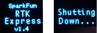
Press and hold the power button until the display illuminates to turn on the device. Similarly, press and hold the power button to turn off the device.
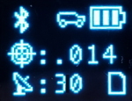
Rover Fix

Upon power up the device will enter either Rover mode or Base mode. Above, the Rover mode is displayed.
- MAC: The MAC address of the internal Bluetooth module. This is helpful knowledge when attempting to connect to the device from your phone. This will change to a Bluetooth symbol once connected.
- HPA: Horizontal positional accuracy is an estimate of how accurate the current positional readings are. This number will decrease rapidly after first power up and settle around 0.3m depending on your antenna and view of the sky. When RTK fix is achieved this icon will change to a double circle and the HPA number will decrease even further to as low as 0.014m.
- SIV: Satellites in view is the number of satellites used for the fix calculation. This symbol will blink before a location fix is generated and become solid when the device has a good location fix. SIV is a good indicator of how good of a view the antenna has. This number will vary but anything above 10 is adequate. We've seen as high as 31.
- Log: This icon will remain animated while the log file is increasing. This is a good visual indication that you have an SD card inserted and RTK Express can successfully record to it.
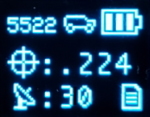
Rover RTK Fix
Once NTRIP is enabled on your phone or RTCM data is being streamed into the Radio port the device will gain an RTK Fix. You should see the HPA drop to 14mm with a double circle bulls-eye as shown above.
Base Survey-In
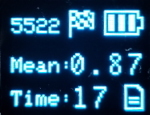
Pressing the Setup button will change the device to Base mode. If the device is configured for Survey-In base mode, a flag icon will be shown and the survey will begin. The mean standard deviation will be shown as well as the time elapsed. For most Survey-In setups, the survey will complete when both 60 seconds have elapsed and a mean of 5m or less is obtained.
Base Transmitting
Once the survey in is complete the device enters RTCM Transmit mode. The number of RTCM transmissions is displayed. By default this is one per second.

The Fixed Base mode is similar but uses a structure icon to indicate a fixed base.
Base Transmitting NTRIP
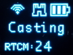
If the NTRIP server is enabled the device will first attempt to connect over WiFi. The WiFi icon will blink until a WiFi connection is obtained. If the WiFi icon continually blinks be sure to check your SSID and PW for the local Wifi.
Once WiFi connects the device will attempt to connect to the NTRIP mount point. Once successful the display will show 'Casting' along with a solid WiFi icon. The number of successful RTCM transmissions will increase every second.
Note: During NTRIP transmission WiFi is turned on and Bluetooth is turned off. You should not need to know the location information of the base so Bluetooth should not be needed. If necessary, USB can be connected to the Config u-blox port to view detailed location and ZED-F9P configuration information.
Output to an Embedded System
Many applications using the RTK Express will use a 3rd party GIS application or mobile app like SW Maps and receive the data over Bluetooth. Alternatively, for embedded applications a user can obtain the NMEA data over serial directly.
For this example we will connect the output from the Data port to a USB to Serial adapter so that we can view the serial data.
Connect the included 4-pin JST to breadboard cable to the Data port. The cable has the following pinout:
- Red - 3.3V
- Green - TX (output from RTK Express)
- Orange - RX (input to RTK Express)
- Black - GND

Open a terminal at 115200bps and you should see NMEA sentences:

The Data connector on the RTK Express is a 4-pin locking 1.25mm JST SMD connector (part#: SM04B-GHS-TB, mating connector part#: GHR-04V-S). 3.3V is provided by this connector to power a remote device if needed. While the port is capable of sourcing up to 600mA, we do not recommend more than 300mA. This port should not be connected to a power source, so if your embedded device has its own power do not connect the red wire.
The parsing of NMEA sentences is straightforward and left to the reader. There are ample NMEA parsing libraries available in C++, Arduino, python, and many more languages.
System Configuration
The RTK Express is an exceptional GNSS receiver out-of-box and can be used with little or no configuration. The following information is for advanced setups including advanced survey-in scenarios and post processing RAWX data.
All the following settings are stored both on internal memory and an SD card if one is detected. The RTK Express will load the latest settings at each power on. If there is a discrepancy between the internal settings and a settings file then the settings file will be used. This allows a group of RTK Expresses to be identically configured using one 'golden' settings file loaded onto an SD card.
Main Menu
To configure the RTK Express attach a USB C cable to the Config ESP32 connector. Open a terminal window at 115200bps; you should see various status messages every second. Press any key to open the configuration menu. Not sure how to use a terminal? Checkout our Serial Terminal Basics tutorial.

Pressing any button will display the Main menu. The Main menu will display the current firmware version and the Bluetooth broadcast name. Note: When powered on, the RTK Express will broadcast itself as either Express Rover-XXXX or Express Base-XXXX depending on which state it is in.
The menus will timeout after 15 seconds of inactivity, so if you do not press a key the RTK Express will return to reporting status messages after 15 seconds.
Configure GNSS Receiver
Pressing 1 will bring up the GNSS Receiver configuration menu. The ZED-F9P is immensely configurable. The RTK Express will, by default, put the ZED-F9P into the most common configuration for rover/base RTK for use with SW Maps.
The GNSS Receiver menu allows a user to change the report rate, dynamic model, and SBAS.

Measurement Frequency can be set by either Hz or by seconds between measurements. Some users need many measurements per second; the RTK Express supports up to 20Hz with RTK enabled. Some users are doing very long static surveys that require many seconds between measurements; RTK Express supports up to 8255 seconds (137 minutes) between readings.
Note: When in base mode, measurement frequency is set to 1Hz. This is because RTK transmission does not benefit from faster updates, nor does logging of RAWX for PPP.
The Dynamic Model can be changed but it is recommended to leave as Portable. For more information, please refer to the ZED-F9P Integration Manual.
SBAS is a Satellite Based Augmentation Service that can, on some GNSS receivers, provide additional precision. As of v1.13 of the ZED-F9P firmware there is a bug that, when SBAS is enabled, causes the RTK status pin to fail to work. SBAS does not improve or detract from the RTK Express precision. We recommend leaving SBAS disabled.
Messages Menu

From this menu a user can control the output of various NMEA, RTCM, RXM, and other messages. Any enabled message will be broadcast over Bluetooth and recorded to SD (if available).
Because of the large number of configurations possible, we provide a few common settings:
- Reset to Surveying Defaults (NMEAx5)
- Reset to PPP Logging Defaults (NMEAx5 + RXMx2)
- Turn off all messages
- Turn on all messages
Reset to Surveying Defaults (NMEAx5) will turn off all messages and enable the following messages:
- NMEA-GGA, NMEA-SGA, NMEA-GST, NMEA-GSV, NMEA-RMC
These five NMEA sentences are commonly used with SW Maps for general surveying.
Reset to PPP Logging Defaults (NMEAx5 + RXMx2) will turn off all messages and enable the following messages:
- NMEA-GGA, NMEA-SGA, NMEA-GST, NMEA-GSV, NMEA-RMC, RXM-RAWX, RXM-SFRBX
These seven sentences are commonly used when logging and doing Precise Point Positioning (PPP) or Post Processed Kinematics (PPK). You can read more about PPP here.
Turn off all messages will turn off all messages. This is handy for advanced users who need to start from a blank slate.
Turn on all messages will turn on all messages. This is a setting used for firmware testing and should not be needed in normal use.
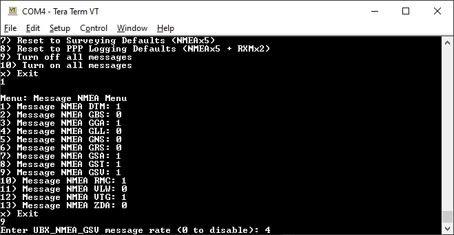
As mentioned is the microSD section of the Hardware Overview there are a large number of messages supported. Each message sub menu will present the user with the ability to set the message report rate.
Note: The message report rate is the number of fixes between message reports. In the image above, with GSV set to 4, the NMEA GSV message will be produced once every 4 fixes. Because the device defaults to 4Hz fix rate, the GSV message will appear once per second.
Base
The RTK Express can also serve as a correction source, also called a Base. The Base doesn't move and 'knows' where it is so it can calculate the discrepancies between the signals it is receiving and what it should be receiving. These differences are the correction values passed to the Rover so that the Rover can have millimeter level accuracy.
There are two types of bases: Surveyed and Fixed. A surveyed base is often a temporary base setup in the field. Called a 'Survey-In', this is less accurate but requires only 60 seconds to complete. The 'Fixed' base is much more accurate but the precise location at which the antenna is located must be known. A fixed base is often a structure with an antenna bolted to the side. Raw satellite signals are gathered for a few hours then processed using Precision Point Position. We have a variety of tutorials that go into depth on these subjects but all you need to know is that the RTK Express supports both Survey-In and Fixed Base techniques.
What is GPS RTK?
Getting Started with U-Center for u-blox
Setting up a Rover Base RTK System
How to Build a DIY GNSS Reference Station
The Base Menu allows the user to select between Survey-In or Fixed Base setups.
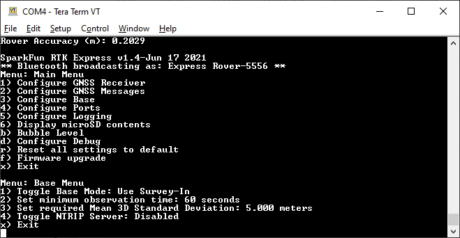
In Survey-In mode, the minimum observation time and Mean 3D Standard Deviation can be set. The defaults are 60s and 5m as directed by u-blox. Don't be fooled; setting the observation time to 4 hours is not going to significantly improve the accuracy of the survey - use PPP instead.
In Fixed mode, the coordinates of the antenna need to be sent. These can be entered in ECEF or Geographic coordinates. Whenever a user enters Base mode by pressing the SETUP button the GNSS receiver will immediately go into base mode with these coordinates and immediately begin outputting RTCM correction data.
NTRIP Server
NTRIP is where the real fun begins. The Base needs a method for getting the correction data to the Rover. This can be done using radios but that's limited to a few kilometers at best. If you've got WiFi reception, use the internet!
Enabling NTRIP will present a handful of new options seen below:

This is a new and powerful feature of the RTK Express. The RTK Express can be configured to transmit its RTCM directly over WiFi to the user's mountpoint. This eliminates the need for a radio link.
Once the NTRIP server is enabled you will need a handful of credentials:
- Local WiFi SSID and password
- A casting service such as RTK2Go or Emlid (the port is almost always 2101)
- A mount point and password
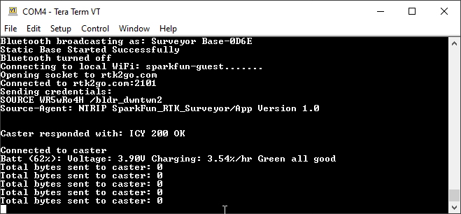
With these credentials set, RTK Express will attempt to connect to WiFi, your caster of choice, and begin transmitting the RTCM data over WiFi. We tried to make it as easy as possible.

Every second a few hundred bytes, up to ~2k, will be transmitted to your mount point.
Configure Ports Menu
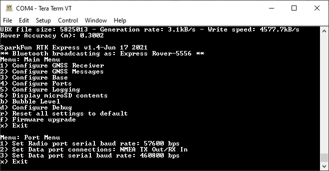
By default the Radio port is set to 57600bps to match the Serial Telemetry Radios that are recommended to be used with the RTK Express (it is a plug and play solution). This can be set from 4800bps to 921600bps.
By default the Data port is set to 460800bps and can be configured from 4800bps to 921600bps. The 460800bps baud rate was chosen to support applications where a large number of messages are enabled and a large amount of data is being sent. If you need to decrease the baud rate to 115200bps or other, but be sure to monitor the MON-COMM message within u-center for buffer overruns. A baud rate of 115200bps and the NMEA+RXM default configuration at 4Hz will cause buffer overruns.
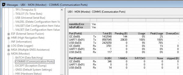
If you must run the data port at lower than 460800bps, and you need to enable a large number of messages and/or increase the fix frequency beyond 4Hz, be sure to verify that UART1 usage stays below 99%. The image above shows the UART1 becoming overwhelmed because the ZED cannot transmit at 115200bps fast enough.
The Data port on the RTK Express is very flexible. It can be configured in four different ways:

Internally the Data connector is connected to a digital mux allowing one of four software selectable setups. By default the Data port will be connected to the UART1 of the ZED-F9P and output any messages via serial.
- NMEA - The TX pin outputs any enabled messages (NMEA, UBX, and RTCM) at a default of 460,800bps (configurable 9600 to 921600bps). The RX pin can receive RTCM for RTK and can also receive UBX configuration commands if desired.
- PPS/Trigger - The TX pin outputs the pulse-per-second signal that is accurate to 30ns RMS. The RX pin is connected to the EXTINT pin on the ZED-F9P allowing for events to be measured with incredibly accurate nano-second resolution. Useful for things like audio triangulation. See the Timemark section of the ZED-F9P Integration Manual for more information.
- I2C - The TX pin operates as SCL, RX pin as SDA on the I2C bus. This allows additional sensors to be connected to the I2C bus.
- GPIO - The TX pin operates as a DAC capable GPIO on the ESP32. The RX pin operates as a ADC capable input on the ESP32. This is useful for custom applications.
Most applications do not need to plug anything into the Data port. Most users will get their NMEA position data over Bluetooth. However, this port can be useful for sending position data to an embedded microcontroller or single board computer. The pinout is 3.3V / TX / RX / GND. 3.3V is provided by this connector to power a remote device if needed. While the port is capable of sourcing up to 600mA, we do not recommend more than 300mA. This port should not be connected to a power source.
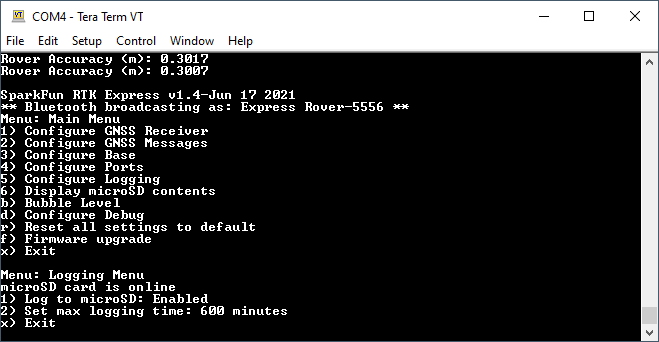
Configure Data Logging Menu
](http://cdn.sparkfun.com/assets/learn_tutorials/1/8/5/7/SparkFun_RTK_Express_-_Logging_Menu.jpg)
Pressing 5 will enter the Logging Menu. This menu will report the status of the microSD card. While you can enable logging, you cannot begin logging until a microSD card is inserted. Any FAT16 or FAT32 formatted microSD card up to 32GB will work. We regularly use the SparkX brand 1GB cards but note that these log files can get very large (>500MB) so plan accordingly.
- Option 1 will enable/disable logging. If logging is enabled, all messages from the ZED-F9P will be recorded to microSD. A log file is created at power on with the format SFE_Express_YYMMDD_HHMMSS.txt based on current GPS data/time.
- Option 2 allows a user to set the max logging time. This is convenient to determine the location of a fixed antenna or a receiver on a repeatable landmark. Set the RTK Express to log RAWX data for 10 hours, convert to RINEX, run through an observation processing station and you’ll get the corrected position with <10mm accuracy. Please see the How to Build a DIY GNSS Reference Station tutorial for more information.
Note: If you are wanting to log RAWX sentences to create RINEX files useful for post processing the position of the receiver please see the GNSS Configuration Menu. For more information on how to use a RAWX GNSS log to get higher accuracy base location please see the How to Build a DIY GNSS Reference Station tutorial.
Configuring ZED-F9P with u-center
Note: Because the ESP32 does considerable configuration of the ZED-F9P at power on it is not recommended to modify the settings of the ZED-F9P. Nothing will break but your changes may be overwritten.
The ZED-F9P module can be configured independently using the u-center software from u-blox by connecting a USB cable to the *Config u-blox’ USB C connector. Settings can be saved to the module between power cycles. For more information please see SparkFun’s Getting Started with u-center by u-blox.
Direct Settings File Editing

Note: All system configuration can also be done by editing the SFE_Express_Settings.txt file (shown above) that is created when a microSD card is installed. The settings are clear text but it is safer and more straightforward to use the serial terminal interface.
Firmware Updates and Customization
The RTK Express is open source hardware meaning you have total access to the firmware and hardware. Be sure to checkout each repo for the latest firmware and hardware information. But for those who want to jump right in and tweak the firmware, we will discuss various methods.
You can check your firmware by opening the main menu by pressing a key at any time.
Updating Firmware From the SD Card
From time to time SparkFun will release new firmware for the RTK Express to add and improve functionality. For most users, firmware can be upgraded by loading the appropriate firmware file from the binaries repo folder onto the SD card and bringing up the firmware menu as shown below:

The firmware upgrade menu will only display files that have the "RTK_Surveyor_Firmware*.bin" file name format so don't change the file names once loaded onto the SD card. Select the firmware you'd like to load and the system will proceed to load the new firmware, then reboot.
Note: The firmware is called RTK_Surveyor_Firmware_vXX.bin even though this product is called the RTK Express. We united the different platforms into one. The RTK Firmware runs on all our RTK products.
Updating Firmware From CLI
The command line interface is also available for more advanced users or users who want to avoid the hassle of swapping out SD cards. You’ll need to download esptool.exe and RTK_Surveyor_Firmware_vXXX_Combined.bin from the repo.
Connect a USB A to C cable from your computer to the ESP32 port on the RTK Express. Now identify the com port the RTK Enumerated at. The easiest way to do this is to open the device manager:

If the COM port is not showing be sure the unit is turned On. If an unknown device is appearing, you’ll need to install drivers for the CH340. Once you know the COM port, open a command prompt (Windows button + r then type ‘cmd’).
Navigate to the directory that contains the firmware file and esptool.exe. Run the following command:
language:c
esptool.exe --chip esp32 --port COM6 --baud 921600 --before default_reset --after hard_reset write_flash -z --flash_mode dio --flash_freq 80m --flash_size detect 0 RTK_Surveyor_Firmware_v13_combined.bin
Note: You will need to modify COM6 to match the serial port that RTK Express enumerates at.

Upon completion, your RTK Express will have the latest and greatest features!
Creating Custom Firmware
The RTK Express is an ESP32 and high-precision GNSS hackers’s delight. Writing custom firmware can be done using Arduino.

Please see the ESP32 Thing Plus Hookup Guide for information about getting Arduino setup. The only difference is that you will need to select ESP32 Dev Module as your board.

Pull the entire RTK Firmware repo and open /Firmware/RTK_Surveyor/RTK_Surveyor.ino and Arduino will open all the sub-files in new tabs. We’ve broken the functional pieces into smaller tabs to help users navigate it. There are a handful of libraries that will need to be installed. To make this easier, we’ve placed a link next to each library that will automatically open the Arduino Library Manager with that library ready for download.
After connecting a USB C cable to the ESP32 Config connector and selecting the correct COM port you should be able to upload new firmware through the Arduino IDE. Note: The RTK Express must be turned on for it to enumerate as a COM port.
Troubleshooting
If you need technical assistance and more information on a product that is not working as you expected, we recommend heading on over to the SparkFun Technical Assistance page for some initial troubleshooting.
If you don't find what you need there, the SparkFun Forums are a great place to find and ask for help. If this is your first visit, you'll need to create a Forum Account to search product forums and post questions.
Resources and Going Further
We hope you enjoy using the RTK Express as much as we have!
Here are the pertinent technical documents for the RTK Express:
- ZED-F9P GNSS Receiver Datasheet
- MAX17048 Fuel Gauge IC
- SparkFun RTK Express GitHub Repo (contains the open source hardware electronics and enclosure)
- SparkFun RTK Firmware GitHub Repo (contains the firmware that runs SparkFun RTK products)
Check out these additional tutorials for your perusal:
GPS Logger Shield Hookup Guide
How to Build a DIY GNSS Reference Station
MicroMod Asset Tracker Carrier Board Hookup Guide
ESP32 Thing Plus Hookup Guide
How to Install CH340 Drivers
Setting up a Rover Base RTK System
How to Build a DIY GNSS Reference Station
learn.sparkfun.com | CC BY-SA 3.0 | SparkFun Electronics | Niwot, Colorado