Real Time Clock Module - RV-8803 (Qwiic) Hookup Guide a learn.sparkfun.com tutorial
Available online at: http://sfe.io/t1111
Introduction
The Real Time Clock Module - RV-8803 (Qwiic) is a Qwiic-enabled breakout board for the RV-8803 RTC module. The RV-8803 boasts some impressive features including a temperature compensated crystal, extremely precise time-keeping, low power consumption, time stamp event input along with a user-programmable timing offset value. It even has a programmable Clock Output to control precise timing for peripheral devices. The RV-8803 also has an improved I2C interface compared to the RV-1805 RTC that removes the need to sequence commands/writes to the device. This is particularly helpful if you are not using our Arduino Library to control the RTC.

In this hookup guide we will go over the unique features of the RV-8803 along with some Arduino examples demonstrating how to use those features. By the end of this tutorial you will have your Real Time Clock Module - RV-8803 (Qwiic) configured and tick-tocking away (well, ticking, maybe not tocking) for your next time-keeping project!
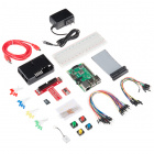
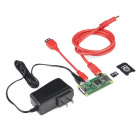
Required Materials
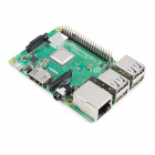
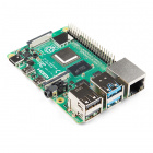
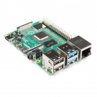
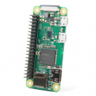
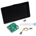
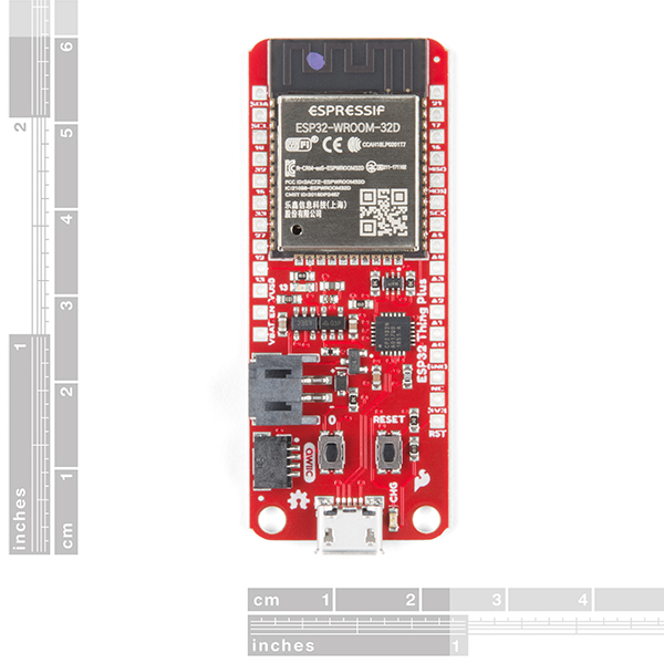
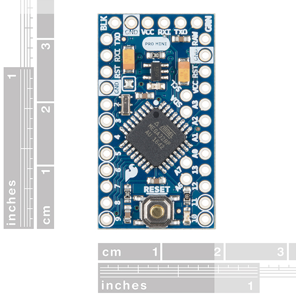
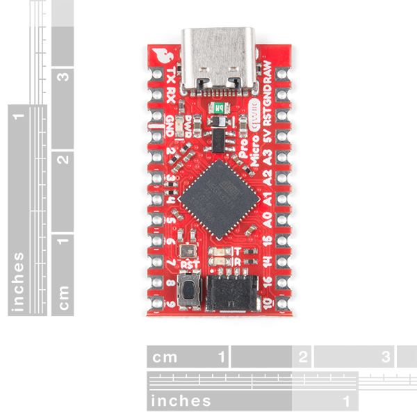
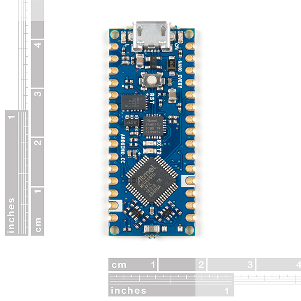
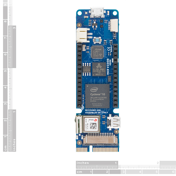
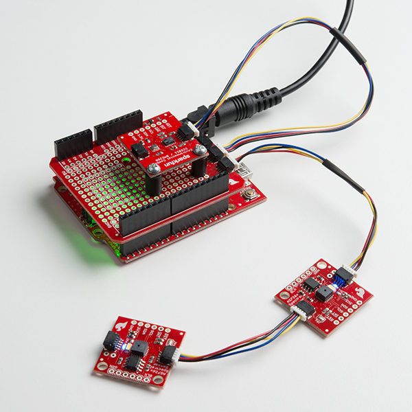
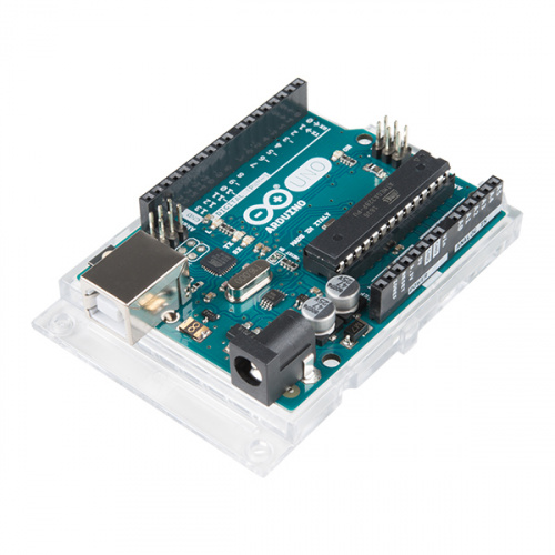
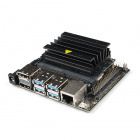
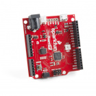
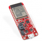
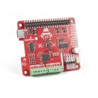
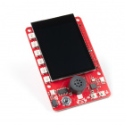
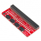
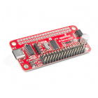
To follow along with this guide you will need a microcontroller to configure and communicate with the RTC Module breakout. Below are a few options that come Qwiic-enabled out of the box:


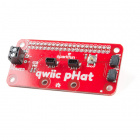
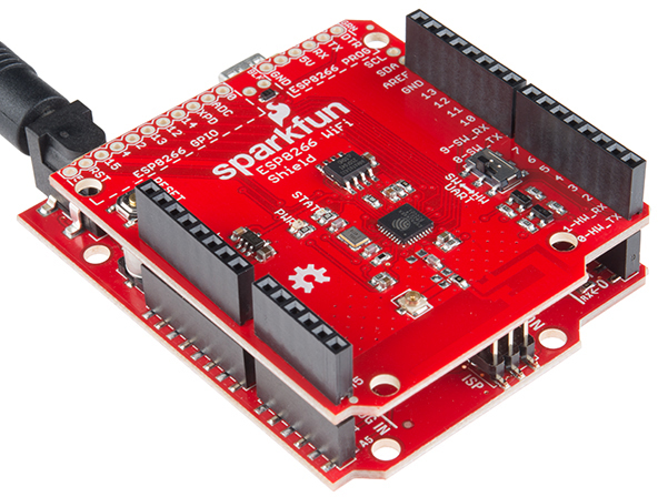
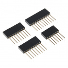
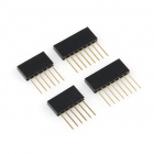
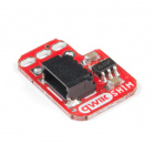
If your chosen microcontroller is not already Qwiic-enabled, you can add that functionality with one or more of the following items:


You will also want at least one Qwiic cable to connect your RTC to your microcontroller.


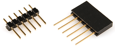
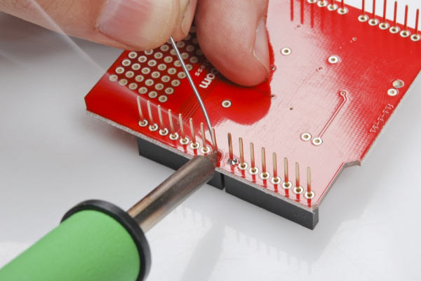
Some of the examples demonstrate how to use more than just the I2C pins. If you want to follow along with them you will need to solder to the EVI, INT, CLKOUT and CLKOE pins broken out on the board. Click the button below to see some recommended soldering tools and materials if you need them.


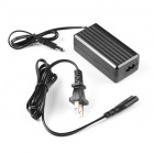
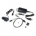
Finally, if you want to fine tune the RV-8803's oscillator for extremely precise time keeping you will need to use an oscilloscope or logic analyzer to calibrate it. Click the button below to see some options for oscilloscopes and logic analyzers if you need one.


Suggested Reading
If you aren't familiar with the Qwiic system, we recommend reading here for an overview:
| Qwiic Connect System |
We also recommend taking a look at the hookup guides for the Qwiic Shields listed above if you plan on using one of them. Brushing up on your skills in I2C is also recommended as all Qwiic sensors communicate via I2C.
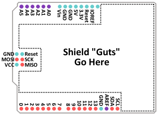
Qwiic Shield for Arduino & Photon Hookup Guide
SparkFun Qwiic Shield for Arduino Nano Hookup Guide
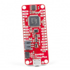
SparkFun Qwiic Shield for Thing Plus Hookup Guide
Hardware Overview
The heart of this breakout is the RV-8803 Real Time Clock module from Micro Crystal. In this section we'll cover most of the features and characteristics of the RV-8803 and this breakout but if you are looking for a more thorough synopsis of the RV-8803, take a look through the Application Manual . The table below lists some of the operating characteristics of the RV-8803.
| Characteristic | Value |
|---|---|
| Operating Voltage Range | 1.5V - 5.5V |
| Time Accuracy (Temp. Compensated -40° to +85°C) | +/-3 ppm |
| Time Accuracy (Temp. Compensated +85° to +105°C) | +/-7 ppm |
| Current Consumption | 240 nA (Typ.) to 350 nA |
| I2C Address | 0x64 |
Power
There are two primary ways to power the SparkFun Real Time Clock Module - RV-8803 (Qwiic). The best and easiest way is through the Qwiic Connectors on either side of the board. When used with any of our Qwiic-enabled boards or our Qwiic Shields, this voltage will be 3.3V. The other power input is the 3.3V pin broken out. The board also includes a 3V 47mAh battery in the 12mm coin cell battery holder on the back for backup power.

Qwiic and I2C Interface
The easiest way to use the Real Time Clock Module - RV-8803 (Qwiic) is with the Qwiic connect system. Just connect the board using a Qwiic Cable to your microcontroller to start talking to it. Alternatively, you can solder to the I2C pins broken out on the board. The 7-bit I2C address is 0x32 (0110010b). This is a hardware set address and there are no alternate slave addresses for the RV-8803. If you need multiple RTC's on a single I2C bus you will need to use a multiplexer or mux like the Qwiic Mux Breakout - 8 Channel.

Pin Descriptions
While the Qwiic interface is the easiest and fastest way to start using your RTC, there are several other pins for extra functionality broken out. You will need to either solder to these pins to make use of them or you can create a temporary connection using something like these IC Hooks. The table below outlines all of the pins broken out on the RTC and summarizes their functionality.
| Pin Label | Pin Function | Input/Output | Functionality Notes |
|---|---|---|---|
| GND | Ground | Input | 0V/Common Voltage |
| 3.3V | Power Supply | Input | Power Supply voltage range is 1.5-3.3V |
| SDA | I2C Data Signal | Bi-directional | Bi-directional data line. Voltage should not exceed power supply (e.g. 3.3V). |
| SCL | I2C Clock Signal | Input | Master-controlled clock signal. Voltage should not exceed power supply (e.g. 3.3V). |
| EVI | Event Input | Input/Output | External event interrupt pin with Time Stamp Function. Active LOW by default. Tied to the button labeled EVI for easy use. |
| INT | Interrupt Output | Output | Open-drain, active LOW. Used to output Alarm, Periodic Countdown Timer, Periodic Time Update and External Event Interrupt signals. Pulled to 3.3V with 100k resistor. |
| CLKOUT | Clock Output | Output | Programmable square wave output for peripheral devices. Available frequencies are 32.768 kHz (default), 1024 Hz or 1Hz. Set on power-up and controlled by the state of CLKOE pin. When disabled, pin is high impedance. |
| CLKOE | Clock Output Enable | Input | Enables and disables the CLKOUT pin. If HIGH, CLKOUT is enabled and is in output mode. If LOW, CLKOUT is disabled. Pin is pulled to GND by default with a 100k resistor. |

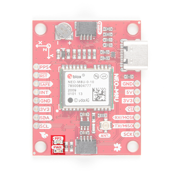
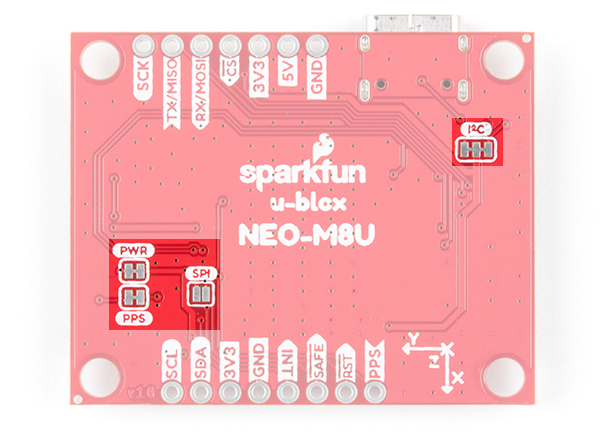
Jumpers
There are two jumpers on the SparkFun Real Time Clock Module - RV-8803 (Qwiic) labeled "I2C" and "LED". The I2C jumper is closed by default and can be opened by severing the trace between the three pads to disconnect the two 4.7k Ohm resistors from the SDA and SCL lines. Open this jumper for if you have many I2C devices on the same bus or to reduce current draw for low-power projects. The LED jumper is closed by default and enables the on board power LED. To open it, simply sever the trace in between the two jumper pads to disconnect the power LED (particularly useful for low-power applications). Note: The power LED is tied to the 3.3V input and is not powered by the backup battery.
 |  |
| I2C Jumper highlighted | LED Jumper Highlighted |
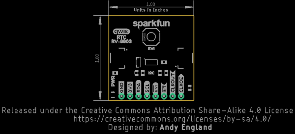
Board Dimensions
The SparkFun Real Time Clock Module - RV-8803 (Qwiic) is built to the standard 1 x 1" size for Qwiic Breakouts. One thing you may notice is this board's lack of mounting holes. In order to fit the 1 x 1" standard for Qwiic Breakouts, there was no space for mounting holes as the battery holder takes the space normally reserved for those mounting holes.
Hardware Assembly
Using the Qwiic system, assembling the hardware is simple. All you need to do is connect your Real Time Clock Module - RV-8803 (Qwiic) to your chosen development board with a Qwiic cable or adapter cable. Otherwise, you can use the I2C pins broken out if you do not have a Qwiic connector on your development board. If you are not using a Qwiic-enabled board, make sure your input voltage and logic are either running at 3.3V or you are running both controller and RTC at the same logic level.

In order to use the full functionality of the RV-8803, you will want to solder to the EVI, INT, CLKOUT and CLKOE pins broken out on this board. If you are not familiar with through-hole soldering, take a look at this tutorial:
How to Solder: Through-Hole Soldering
September 19, 2013
With everything connected properly, we're ready to move on to uploading a sketch and start keeping track of time!
RV-8803 Arduino Library
The easiest way to install the library is to search for SparkFun RV-8803 in the Arduino Library Manager tool. You can also manually install the RV-8803 Library from the GitHub Repository or you can download it by clicking the button below.
Library Functions
The list below outlines all of the functions of the library with some quick descriptions of what they do. The examples cover most of the functions so we recommend going through those first.
Device Setup & Settings
bool begin(TwoWire &wireport);- Initializes the RV-8803 on the I2C bus.void set12Hour();- Configures the microcontroller to convert to 12 hour mode.void set24Hour();- Configures the microcontroller to not convert from the default 24 hour mode.bool is12Hour();- Returns true if the microcontroller is configured to 12 hour mode.bool isPM();- Returns true if the microcontroller is in 12 hour mode and the RTC has an hours value greater than or equal to 12 (Noon).char* stringDateUSA();- Returns the date in MM/DD/YYYY format.char* stringDate();- Returns the date in the DD/MM/YYYY format.char* stringTime();- Returns the time in hh:mm:ss (Adds AM/PM if in 12 hour mode).char* stringTimeStamp();- Returns the most recent timestamp captured on the EVI pin (if the EVI pin has been configured to capture events). The format is hh:mm:ss:HHXM with \0 terminator where 'X' is 'A' or 'P' depending on the time of day.char* stringTime8601();- Returns timestamp in ISO 8601 format (yyyy-mm-ddThh:mm:ss).bool setTime(uint8_t sec, uint8_t min, uint8_t hour, uint8_t date, uint8_t month, uint8_t year, uint8_t day);- Sets the RTC's time registers using a set of individual variables.bool setTime(uint8_t * time, uint8_t len);- Sets the RTC's time registers using an array with the following structure;{HUNDREDTHS, SECONDS, MINUTES, HOURS, WEEKDAY, DATE, MONTH, YEAR}bool setHundredthsToZero();- The hundredths register is read only so instead of writing to it, this function uses the Reset Bit Function on the RV8803 to set this register to zero. Check out section 4.13 of the RV-8803 Application Manual for more information about this function.bool setSeconds(uint8_t value);- Sets the seconds register tovalue.bool setMinutes(uint8_t value);- Sets the minutes register tovalue.bool setHours(uint8_t value);- Sets the hours register tovalue.bool setDate(uint8_t value);- Sets the date register tovalue.bool setMonth(uint8_t value);- Sets the month register tovalue.bool setYear(uint16_t value);- Sets the year register tovalue.bool setWeekday(uint8_t value);- Sets the weekday register tovalue.bool setToCompilerTime();- Sets the RTC to the time from the last build and uses it as current time.bool setCalibrationOffset(float ppm);- Loads the calibrated PPM offset to the RV8803_OFFSET register.float getCalibrationOffset();- Returns the calibration offset value stored in the RV8803_OFFSET register.
Reading from the RTC
bool updateTime();- Move the time registers (hours, mins, secs, etc.) from the RV-8803 into the_timearray that lives on the microcontroller. Needs to be called before printing time or date.uint8_t getHundredths();- Returns_timevalue from the hundredths register.uint8_t getSeconds();- Returns_timevalue from the seconds register.uint8_t getMinutes();- Returns_timevalue from the minutes register.uint8_t getHours();- Returns the_timevalue from the hours register.uint8_t getDate();- Returns the_timevalue from the date register.uint8_t getWeekday();- Returns the_timevalue from the weekday register.uint8_t getMonth();- Returns the_timevalue from the month register.uint16_t getYear();- Returns the_timevalue from the year register.uint8_t getHundredthsCapture();- Returns the captured value from the hundredths register (Time Stamp).uint8_t getSecondsCapture();- Returns the captured value from the seconds register (Time Stamp).
Alarm & Interrupt Functionality
Since the RV-8803 has three types of alarms/interrupts, this list is quite extensive so we've split it up into the individual alarm and interrupt functionalities.
External Event Interrupt
bool setEVICalibration(bool eviCalibration);- Enables or disables the the External Event Interrupt (EVI) button and pin.bool setEVIDebounceTime(uint8_t debounceTime);- Sets the debounce time for the EVI pin and button. Can be set to None, 256 Hz, 64 Hz or 8 Hz.bool setEVIEdgeDetection(bool edge);- Sets the EVI to fire on either the rising or falling edge of the signal.bool setEVIEventCapture(bool capture);- Enables or disables the EVI Event Capture function.uint8_t getEVIDebounceTime();- Returns the value set for the EVI Debounce time.bool getEVICalibration();- Returns whether or not the EVI functionality is enabled or disabled.bool getEVIEdgeDetection();- Returns whether the EVI function is set to rising or falling edge.bool getEVIEventCapture();- Returns whether or not the EVI Event Capture function is enabled or disabled.
Countdown Interrupt
bool setCountdownTimerEnable(bool timerState);- Enables or disables the Periodic Countdown Timer interrupt function.bool setCountdownTimerFrequency(uint8_t countdownTimerFrequency);- Sets the time for the Periodic Countdown Timer. Built in values are 4096 Hz, 60 Hz, 1 Hz and 1/60 Hz.bool setCountdownTimerClockTicks(uint16_t clockTicks);- Sets the number of clock ticks to count for the Countdown Timer. Refer to the Example 4B - Countdown Interrupt overview in the next section of this guide for more information on calculating the number of clock ticks for your timer.bool getCountdownTimerEnable();- Returns whether or not the Countdown Timer is enabled or disabled.uint8_t getCountdownTimerFrequency();- Returns the frequency set for the Countdown Timer.uint16_t getCountdownTimerClockTicks();- Returns the number of clock ticks set for the Countdown Timer.
Periodic Interrupt
bool setPeriodicTimeUpdateFrequency(bool timeUpdateFrequency);- Sets the frequency of the Periodic Time Update interrupt function. Can be 1 Hz (one second) or 1/60 Hz (one minute).bool getPeriodicTimeUpdateFrequency();- Returns the time set for the Periodic Time Update interrupt frequency.
Alarm Interrupt
void setItemsToMatchForAlarm(bool minuteAlarm, bool hourAlarm, bool dateAlarm, bool weekdayOrDate);- Function to select which time values need to match to trigger an alarm. Can be set to minutes, hours, date or weekday+date. Setting the bit to 1 means the RTC will not look to match that item for an alarm.bool setAlarmMinute(uint8_t minute);- Set the minute value for the RTC to match to trigger an alarm.bool setAlarmHour(uint8_t hour);- Set the hour value for the RTC to match to trigger an alarm.bool setAlarmWeekday(uint8_t weekday);- Set the weekday value for the RTC to match to trigger an alarm.bool setAlarmDate(uint8_t date);- Set the date value for the RTC to match to trigger an alarm.uint8_t getAlarmMinute();- Returns the minute value set for the RTC to match for an alarm.uint8_t getAlarmHour();- Returns the hour value set for the RTC to match for an alarm.uint8_t getAlarmWeekday();- Returns the weekday value set for the RTC to match for an alarm.uint8_t getAlarmDate();- Returns the date value set for the RTC to match for an alarm.
Configuring the Clock Out (CLKOUT) pin
These two functions are for enabling and configuring the Clock Out pin. Use these with the setCalibrationOffset(); and getCalibrationOffset(); functions to fine tune your RTC. Refer to Example 6 - Fine Tuning in the next section of this guide for more information.
bool setClockOutTimerFrequency(uint8_t clockOutTimerFrequency);- Sets the frequency of the square wave output from the Clock Out pin. Available frequencies are 1Hz, 1024Hz and 32,768 Hz.uint8_t getClockOutTimerFrequency();- Returns the frequency set for the Clock Out.
Extra Functions
uint8_t BCDtoDEC(uint8_t val);- Convert values in the RTC from Binary Coded Decimal to Decimal.uint8_t DECtoBCD(uint8_t val);- Convert values in the RTC from Decimal to Binary Coded Decimal.bool readBit(uint8_t regAddr, uint8_t bitAddr);- Read a single bit from the selected register.uint8_t readTwoBits(uint8_t regAddr, uint8_t bitAddr);- Read two bits from the selected register.bool writeBit(uint8_t regAddr, uint8_t bitAddr, bool bitToWrite);- Write a selected bit to a register.bool writeBit(uint8_t regAddr, uint8_t bitAddr, uint8_t bitToWrite);- Write a selected bit to a register.uint8_t readRegister(uint8_t addr);- Read a specific register.bool writeRegister(uint8_t addr, uint8_t val);- Write a specific register.bool readMultipleRegisters( uint8_t addr, uint8_t * dest, uint8_t len);- Read multiple consecutive registers.bool writeMultipleRegisters(uint8_t addr, uint8_t * values, uint8_t len);- Write multiple consecutive registers.
Next up we'll go over the examples included with the RV-8803 Arduino Library.
Arduino Examples
Example 1 - Set Time
This example demonstrates how to set the time on the RV-8803 RTC to either the compiler time or a custom time. This is necessary to set the RTC's internal clock to keep time so long as the RTC has power. First, the code initializes the RV-8803 on the I2C bus and verifies the microcontroller can talk to it. Next, it sets the internal clock. Take note of the following bits of code to set the RTC time to either the compiler or a custom time:
When setting a custom time, change these values at the beginning of the sketch:
language:c
//The below variables control what the date and time will be set to
int sec = 2;
int minute = 47;
int hour = 14; //Set things in 24 hour mode
int date = 2;
int month = 3;
int year = 2020;
int weekday = 2;
In the setup, this code selects either compiler time or custom time:
language:c
if (rtc.setToCompilerTime() == false) {
Serial.println("Something went wrong setting the time");
}

//Uncomment the below code to set the RTC to your own time
/*if (rtc.setTime(sec, minute, hour, weekday, date, month, year) == false) {
Serial.println("Something went wrong setting the time");
}*/
If everything goes correctly here your RTC's internal clock will either be set to the compiler time or your custom time using the variables defined earlier in the sketch. Open the Arduino Serial Monitor, set the baud rate to 115200 and the code will print out over serial whether or not this was successful. If you have never worked with the Arduino Serial Monitor or other serial terminal programs, check out our Serial Terminal Basics tutorial. You can check the accuracy of the time set here by running the second example.
Example 2 - Print Time
This example shows how to request the time from the RTC after it has been set. The code starts by initializing the RV-8803 on the I2C bus then attempts to to move the values from the RV-8803's time registers to the microcontroller's _time array using the updateTime(); function. If that retrieval is successful, the code prints the time data (date, hour, mins, etc.) over serial. Open up the Serial Monitor and set the baud to 115200 and watch the time fly by, literally!
The code defaults to printing the date in the US format (mm/dd/yyyy) so if you'd like to switch it to the more commonly used dd/mm/yyyy format, adjust this section of the code:
language:c
String currentDate = rtc.stringDateUSA(); //Get the current date in mm/dd/yyyy format
//String currentDate = rtc.stringDate()); //Get the current date in dd/mm/yyyy format
updateTime(); function must be called before attempting to read the time from the RV-8803.Example 3 - Set Hundredths
We have split this example into two "sub-examples" to demonstrate the ways to reset the hundredths register. The hundredths register is read only so we cannot write to it like the other time variables (seconds, minutes, etc.). Instead, we "set" this register by writing to the RESET bit on the RV-8803. This function is covered in more detail in section 4.13 of the RV-8803 Application Note.
Example 3A - Set Hundredths (Software)
This example initializes the RV-8803 and then configures the RTC to reset the hundredths register on a serial prompt to the microcontroller. After uploading the code, open up the serial monitor (with the baud set to 115200 like the previous examples) and send an "r". Your microcontroller will write to the RESET bit on the RV-8803 to "set" the hundredths register to 00. If you want to reset the hundredths register again, simply send another "r" through your serial monitor.
Example 3B - Set Hundredths (Hardware)
This example is near identical to the Software example above but also enables resetting the hundredths register using the RV-8803's EVI pin along with resetting it via serial commands. The EVI pin can be toggled either through the on board button or by controlling the EVI pin with a GPIO pin on your microcontroller (or other external control mechanism). Resetting the hundredths register using the EVI pin is enabled by this line of code:
language:c
rtc.setEVICalibration(ENABLE);
Enabling this bit tells the RV-8803 to reset the hundredths register when it sees a LOW event on the EVI pin. This event can either be triggered by pressing the button or pulling the EVI pin LOW. The code will print the RV-8803 is ready for a button press or other event on the EVI pin. When that pin is triggered it prints out the the hundredths value pulled from the RV-8803's time register over serial. If you want to verify the register is set, open the serial monitor and toggle the EVI pin and the code should print out: Hundredths set to: 00.
The code also toggles the RESET bit back to 0 so it is ready for another event if you want to set the hundredths register back to 00 again.
Example 4 - Interrupts
Since the RV-8803 has several types of interrupts, we have split the interrupt examples into sub-examples as well. Each one will enable and configure a different interrupt and demonstrate how to use it. To integrate any of these examples to your project, just tie the INT pin to a GPIO on your microcontroller that is usable for external interrupts to trigger whatever behavior you would like when one of these alarms or timers are triggered. If you have never worked with processor interrupts before, we have a tutorial covering how to work with them in Arduino here.
Example 4A - Alarm Interrupt
This example configures the Alarm Interrupt function. The code first defines the variables the RV-8803 will look to match to trigger the Alarm Interrupt and selects which of these variables the RTC will look to match to trigger the alarm. To set it to a different time simply edit these values:
language:c
uint8_t minuteAlarmValue = 55; //0-60
uint8_t hourAlarmValue = 0; //0-24
uint8_t weekdayAlarmValue = 0; //0-6
uint8_t dateAlarmValue = 0; //1-31

#define MINUTE_ALARM_ENABLE true
#define HOUR_ALARM_ENABLE false
#define WEEKDAY_ALARM_ENABLE false
#define DATE_ALARM_ENABLE false
Setting the the various Alarm Enable variables (e.g. MINUTE_ALARM_ENABLE) to true will configure the RV-8803 to check to match that variable to trigger an alarm and, as expected, setting it to false prevents the RV-8803 from matching the variable for the alarm interrupt. The example defaults to trigger an alarm every hour when the minutes value reaches 55.
With the variables defined and enabled/disabled, the code initializes the RV-8803, configures it to trigger an alarm and the calls the values for each time variable (minutes, hours, etc.). The main loop checks if the alarm interrupt flag (FLAG_ALARM) has been triggered using the 'getInterruptFlag` function and, if the alarm is triggered, drives the INT pin LOW and prints over serial the alarm has been triggered.
Lastly, it clears the alarm flag to reset the RTC for the next alarm trigger. If you want to clear the entire flag register on an alarm trigger, uncomment this line:
language:c
//rtc.clearAllInterruptFlags();
Example 4B - Countdown Interrupt
This example demonstrates how to configure a periodic signal interrupt based on a countdown timer and explains how to calculate the proper values for the countdown timer. The countdown timer values require some math to calculate how many clock ticks (0-4095) we want to count along with the length of those ticks (4096 Hz, 64 Hz, 1 Hz, 1/60 Hz) in order to designate the period of the countdown timer. Click the button below to take a look at the table for more information on how the countdown timer interval is calculated:
After initializing the RV-8803, the example configures a ~3.5 second interrupt. To do this, we first choose 60 Hz as our timer frequency since we want our timer longer than 1 second but still want a small enough time range (or resolution) to easily set the interrupt to fire at 3.5 secs and not 3 or 4 seconds. Next, we'll convert 3.5 seconds to 3500 mS since our resolution @60 Hz is 15.625mS/LSB. Finally, to figure out how many ticks are needed for a 3.5 sec interval, we divide the time we want by the resolution of the clock frequency: 3500 / 15.625 = 224 Clock Ticks. With everything calculated, our code configuring the Countdown Timer Interrupt looks like this:
language:c
rtc.disableAllInterrupts();
rtc.setCountdownTimerFrequency(COUNTDOWN_TIMER_FREQUENCY_64_HZ);
rtc.setCountdownTimerClockTicks(224);
rtc.enableHardwareInterrupt(TIMER_INTERRUPT);
rtc.setCountdownTimerEnable(ENABLE);

lastInterruptTime = millis(); //Change millis() to micros() if you end up using the 4096 Hz counter
The loop checks if the countdown interrupt flag (FLAG_TIMER) has been updated using the getInterruptFlag function. If it has, it clears that flag and prints the time between interrupts (in milliseconds) over serial.
Example 4C - Periodic Interrupt
The last interrupt example demonstrates how to generate a periodic pulse from the RV-8803. This is very similar to the previous example but instead of setting a custom time between interrupts, we configure the RV-8803 to pulse the interrupt pin every second or every minute using the setPeriodicTimeUpdateFrequency(); function. The code defaults to a 1 second period but you can change to 1 minute by editing this line:
language:c
rtc.setPeriodicTimeUpdateFrequency(TIME_UPDATE_1_SECOND); //Can also use TIME_UPDATE_1_MINUTE
The loop checks if the periodic interrupt flag (FLAG_UPDATE) has been updated using the getInterruptFlag function. If it has, it clears that flag and prints the time between interrupts (in milliseconds) over serial.
Example 5 - Timestamp
This example demonstrates how to get a timestamp of an event generated on the EVI pin either by pressing the button on the RTC or toggling the EVI pin from a microcontroller-generated event. First, just like the other examples, we need to initialize the RV-8803 on the I2C bus. Next, we enable and configure the timestamp function:
language:c
rtc.setEVIEventCapture(ENABLE); /
rtc.setEVIDebounceTime(EVI_DEBOUNCE_256HZ);
//rtc.setEVIEdgeDetection(RISING_EDGE); // Uncomment to set event detection to button release instead of press
The main loop waits for the FLAG_EVI register to update from an external event on the EVI pin using the getInterruptFlag(); function like the other interrupt examples. If that flag is updated and cleared, we capture the date and time stamp of the interrupt and print that data over serial.
Example 6 - Fine Tuning
How to Use an Oscilloscope
February 25, 2014
Using the USB Logic Analyzer with sigrok PulseView
June 25, 2018
This last example demonstrates how to calibrate the RV-8803's oscillator using the Clock Output pin. Again, we first initialize the RV-8803 on the I2C bus. Next, we zero out any calibration settings that may be present and set the clock output to a 1 Hz square wave:
language:c
rtc.disableAllInterrupts();
rtc.setCalibrationOffset(0); //Zero out any calibration settings we may have
rtc.setPeriodicTimeUpdateFrequency(CLOCK_OUT_FREQUENCY_1_HZ); //Set our clockout to a 1 Hz square wave,
rtc.enableHardwareInterrupt(UPDATE_INTERRUPT); //Enable the interrupt
Next, we'll use our oscilloscope or logic analyzer to look at exactly how precise the 1 HZ square wave is (It could be off by a few microseconds, which can add up over time). In order to do this, you'll need to time the output of the INT pin. Once you have the RTC's output frequency measured carefully, go ahead and replace the "dummy" frequency that we've put in the example by default (1.0000012 Hz) with the one that you've just measured. We then take the difference between this measured frequency and the desired 1 Hz clock signal, and multiply it by 1,000,000 to get the Parts Per Million (PPM) offset that we must give to our oscillator.
language:c
float measuredFrequency = 1.0000012; //Measured frequency in Hz (CHANGE THIS TO YOUR MEASURED VALUE)
float newPPM = (measuredFrequency - 1) * 1000000; //Calculate PPM difference between measuredFrequency and our desired 1 Hz wave
Once we've replaced our measuredFrequency, we can uncomment the below line that actually places this new setting into the RTC to change the offset for the crystal. Make sure you don't do this until you've changed your measuredFrequency. From here, you should be able to upload code and see the square wave oscillator closer to a perfect 1 Hz. If not, recomment the below line, upload, and try again.
language:c
//rtc.setCalibrationOffset(newPPM); //Uncomment this line after you have changed the value of measuredFrequency to load the new calibration into the RTC
Troubleshooting
If your product is not working as you expected or you need technical assistance or information, head on over to the SparkFun Technical Assistance page for some initial troubleshooting.
If you don't find what you need there, the SparkFun Forums are a great place to find and ask for help. If this is your first visit, you'll need to create a Forum Account to search product forums and post questions.
Resources and Going Further
Now that your Real Time Clock Module RV-8803 (Qwiic) is up and keeping track of time it's time to integrate it into your next time-keeping project!
For more information about the Real Time Clock Module RV-8803 Breakout (Qwiic), take a look at the resources below:
- Schematic
- Eagle Files (ZIP)
- Board Dimensions (PNG)
- Real-Time Clock Module GitHub Repository
- SparkFun RV-8803 Arduino Library
- RV-8803 Application Manual
Not sure what type of project you can use your RV-8803 in? Take a look at these tutorials for some inspiration for time-keeping projects:
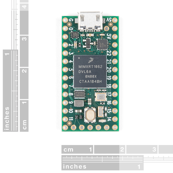
Getting Started with the Teensy
Real Time Clock Module Hookup Guide
Qwiic Real Time Clock Module (RV-1805) Hookup Guide
SparkFun gator:RTC Hookup Guide
Or check out some of these blog posts for project ideas:
learn.sparkfun.com | CC BY-SA 3.0 | SparkFun Electronics | Niwot, Colorado