Getting Started with the Teensy a learn.sparkfun.com tutorial
Available online at: http://sfe.io/t385
Introduction
The Teensy line is a collection of microcontrollers from PJRC, based around several different powerful ICs. This basic getting started guide will help you start using the Teensy that’s best for your project.
Image may be NSFW.
Clik here to view.
The Teensy 3.1, the Teensy++ 2.0, and the Teensy LC.
Required Materials
We recommend the beginner Tool Kit for soldering any of the Teensy boards.
Alternatively, if you are planning on doing a lot of intense soldering, you can also use the following wishlist as a guide.
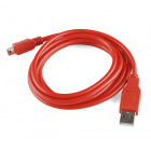
You will also need the appropriate USB cable for the Teensy board with which you are working. The following boards work with the micro-USB cable:


The Teensy++ 2.0 works with the mini-USB cable:

You will also need the appropriate headers for your project. There are several different options available.
Suggested Reading
If you aren’t familiar with the following concepts, we recommend reading these articles first before continuing with this getting started guide.
- How to Solder- Through Hole
- Serial Communication
- Installing Arduino IDE
- Installing Arduino Libraries
- I2C
- Serial Peripheral Interface
- Logic Levels
Hardware Overview
Each Teensy board has its own key features which are covered here. For individual pinout diagrams and detailed schematic information, please check PJRC’s page here.
Teensy ++ 2.0
This Teensy board is the only AVR-based Teensy that SparkFun carries. It runs off of the AT90USB1286, an 8 bit AVR running at 16MHz. It also has the largest footprint of all of the Teensy boards, at 1.375 in2.
| Feature | Number Available |
|---|---|
| PWM | 9 |
| Analog In | 8 |
| I/O | 46 |
| Serial Port | 1 |
| I2C Port | 1 |
| SPI Port | 1 |
| Flash | 128K |
| RAM | 8K |
The push button on the end of the Teensy 2.0 ++ is a RESET button. This is also used during programming the Teensy with Teensyduino, discussed later.
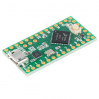
Teensy LC
The Teensy LC is 0.98 in2. It runs off of the 32 bit ARM Cortex-M0+ at 48MHz and runs at 3.3V.
The Digital to Analog converter is on pin A12 of the microcontroller. Pin 17 outputs voltages up to the supplied Vin voltage, at 8mA.
Pins D5, D16, D17 and D21 can source signals up to 20mA. All other pins are limited to 5mA.
| Feature | Number Available |
|---|---|
| PWM | 10 |
| Analog In | 13 |
| I/O | 27 |
| Serial Port | 3 |
| I2C Port | 2 |
| SPI Port | 2 |
| Touch Sense Pins | 11 |
| Flash | 62K |
| RAM | 8K |
The pushbutton on the LC is not a reset button but instead triggers HalfKay mode. This allows the board to reboot to the newest code or accept new uploaded code.
Teensy 3.1
The Teensy 3.1 is the same size and footprint as the Teensy LC but more powerful. This runs off of the MK20DX256 IC, which is a 32 bit ARM Cortex-M4. It is also 5V tolerant on its digital I/O pins and can provide up to 3.3V at 100mA to other devices. The analog pins are 3.3V tolerant only.
| Feature | Number Available |
|---|---|
| PWM | 12 |
| Analog In | 21 |
| I/O | 34 |
| Serial Port | 3 |
| I2C Port | 2 |
| SPI Port | 1 |
| Real Time Clock | 1 |
| Touch Sense pins | 12 |
| Flash | 256K |
| RAM | 64K |
The pushbutton on the 3.1 is a reboot trigger and does not reset the entire system, similar to the pushbutton on the LC. In order to reset the board, you must access the RESET test point on the bottom of the board.
Image may be NSFW.
Clik here to view.
Teensy 3.1 Reset pad.
Soldering Options
When it comes to soldering your Teensy, there are many different options available to you.
Solder Directly Into your Circuit
We generally recommend against soldering directly between any two boards you want to connect – if something burns out or is connected incorrectly, you’ve set yourself up for a lot of annoying rework (and the danger of ripping a pad off of the board).
Image may be NSFW.
Clik here to view.
Soldering your Teensy directly to the board leads to a small profile, but you run the risk of needing to desolder a lot of pins!
One benefit of soldering directly to your circuit however is that it gives a very small profile for the project. If you plan on doing this, we recommend testing your circuit design with Alligator clips or Pig-tail cables before hand to verify functionality.
Solder Headers
Most users prefer using male headers on the Teensy and matching female headers on other boards into which the Teensy fits.
If you plan on using this method, you must ensure you solder the headers on straight, otherwise you’re going to have a hard time inserting or removing the Teensy from other boards.
We recommend inserting headers into a breadboard and soldering the Teensy on from there.
Image may be NSFW.
Clik here to view.
Teensy 3.1 inserted in a breadboard for soldering. Half the pins are soldered and half aren’t.
Using male headers with the Teensy allows you to solder the headers on nice and straight, preventing crooked header insertion. As you can see from the image above however, if you intend to use the Teensy LC or Teensy 3.1 on a breadboard, you cannot solder all of the headers.
Image may be NSFW.
Clik here to view.
These pins aren’t breadboard compatible!
If you’ve already soldered together a board that works with the Teensy LC/3.1, you can simply line your headers up in that board to hold them straight while soldering to the Teensy.
Image may be NSFW.
Clik here to view.
The male headers for the Teensy are being held straight by this Teensy Arduino Shield Adapter.
Once the headers are lined up straight, it’s easy to simply ‘plug’ the Teensy into the headers and solder everything together.
Image may be NSFW.
Clik here to view.
You can see the Teensy lined up on the headers, waiting to be soldered.
You can also solder female headers or stackable headers onto the top of the board, allowing other boards to be plugged into the top of the Teensy.
Image may be NSFW.
Clik here to view.
Teensy with stackable female headers on top, allowing the Audio shield to be plugged in and the Teensy to fit into a breadboard.
If you do solder your headers on like this, keep in mind it may limit your access to the push button on board, requiring you to break out the reboot/reset signal from the header pin.
What about Those Additional Headers on the LC/3.1?
Inner Headers
Image may be NSFW.
Clik here to view.
Inner headers - what to do with those?!
There are a few options to work with these pins. You can:
a) Leave them unconnected (boring!)
b) Solder wires to the pins as you find uses for them
c/d) Solder headers on the top/bottom
If you go for options c or d, there’s an easy way to solder connectors on there without driving yourself crazy attempting to solder a lonely pin by itself.
If you are using male headers, you can use pliers to push/pull one of the pins out. This will allow you to use the spacer to hold the pins straight, but will remove the non-compatible pin.
Image may be NSFW.
Clik here to view.
Removing the unnecessary pin using pliers.
If you are using female headers, this method won’t work, but you can still use the pliers to pull out the unnecessary pins.
Image may be NSFW.
Clik here to view.
Simply pull the header pin out, and out of the way!
Once the header strip has been modified, simply line it up with those holes, and solder them.
SMD Headers
Both the 3.1 and LC Teensy boards have SMD pins on the board bottom that you can solder to. If you know you will need access to these pins, we recommend that you solder the headers onto the top side of your Teensy.
If you already have another Teensy soldered, you can use this as a soldering jig to keep the headers straight, as shown below.
Image may be NSFW.
Clik here to view.
Headers are soldered on the top of the board, enabling access to the SMD pads on the bottom.
With the headers soldered onto the Teensy this way, the user has access to all of the SMD pads on the bottom of the board. Keep in mind however, this does minimize access to the pushbutton, so balance that with your project needs.
If you need help with soldering to the SMD pads on the bottom of the board, please check out our tutorial here.
Programming
To start working with the Teensy, all you need to do is plug in your USB cable to your computer and your Teensy board. There are two options for programming the Teensy boards - your favorite C compiler or the Arduino IDE.
Arduino
Installation: You will need to download the Teensyduino add-on for Arduino. If you have not already installed the Arduino IDE, please do that now. Check out our tutorial on that if you need help.
You can find the Teensyduino download from PJRC here. Please follow their installation instructions for the most up-to-date version of the Teensyduino. You will also need to select which Teensy-compatible libraries you’d like to install at that time. If you aren’t sure which libraries you will want, you can always download them and install them later from the curated list.
Programming the Teensy:
When you first plug the Teensy in, the appropriate drivers will be installed (if using a Windows machine). Your Teensy should default to the standard Blink sketch. You should see the LED blinking, as a quick check to make sure your board is functioning.
Open up the Arduino IDE, and select the appropriate Teensy board from the Board menu. This will provide you with additional options in the Tools menu.
Image may be NSFW.
Clik here to view.
Drop-down options in Arduino for Teensy boards.
If you would like to use the Teensy as an HID, MIDI, or user interface device (such as a keyboard or mouse), you can select that option from the USB Type menu.
The CPU speed can be changed for low-power applications.
The Keyboard Layout option can be updated to your preferred style.
Press the button on the Teensy to open the Teensy loader program. You should see this window:
Image may be NSFW.
Clik here to view.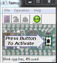
Teensy Loader Window
Verify your example code, and upload to the board as usual in the Arduino IDE. You will need to hit the on-board button once the IDE has compiled the code to finish uploading it to your Teensy. You should only need to do this the first time you upload code for the duration that your Teensy is powered.
C Compiler
This is typically a more advanced option. For step-by-step instructions on using a C-compiler for the Teensy, please check out PJRC’s directions here. You will still need to download and install the Teensyduino and modify the Arduino files to use the Makefile for the Teensy boards.
Additional support for other languages is slowly being added. Please check here for more information.
Resources and Going Further
Going Further
Now that you have a basic understanding of working with the Teensy, it’s time to start building projects with one! Make sure to check out the schematic for your particular Teensy when building any new projects.
Image may be NSFW.
Clik here to view.
Teensy schematics are available here.
If you have any feedback, please visit the comments or contact our technical support team at TechSupport@sparkfun.com.
Additional Resources
Check out these additional resources for more information and other project ideas.
- PJRC Homepage
- Teensy 2.0 ++ AT90USB Datasheet
- Teensy 3.1 ARM Cortex-M4 Datasheet
- Teensy Arduino Shield Adapter
- Teensy XBee Adapter
- RGB Panel Jumbotron
learn.sparkfun.com |CC BY-SA 3.0 | SparkFun Electronics | Niwot, Colorado