Teensy XBee Adapter Hookup Guide a learn.sparkfun.com tutorial
Available online at: http://sfe.io/t364
Introduction
The Teensy is a great way to get more computing power than an Arduino, and in less space. When a decently ranged, no-frills wireless serial link is required, the XBee series is a great solution. The Teensy 3.1 XBee Adapter joins the two with ease and brings wireless to your Teensy projects. This tutorial will demonstrate the basics of using the adapter board.

This tutorial demonstrates:
- How to initialize Teensy 3.1 HW serial
- How to initialize Teensy 3.1 SW serial using softwareSerialAlt library
- The basics of packetizing data.
- How to make a simple controller that effects something far away
Required Materials
At a minimum, you’ll need an XBee explorer, two XBees, a Teensy and the adapter board. Here’s a list of things you’ll need if you want two Teensy XBee radio stations that are both off-the-grid, plus some useful extras.
Required Basic Shop Tools
- Soldering iron and flux core solder
- Spare wire
- X-acto or knife for cutting traces (possibly)
Software Requirements
Suggested Reading
Before getting started, there are a few concepts that you should be familiar with. If you haven’t used a Teensy or XBee before, read these tutorials before continuing:
- Getting Started with the Teensy - How to install Teensyduino, comparison of the Teensy 3.1 and LC, and soldering options.
- Exploring XBees and XCTU - Guide to configuring the XBees using the XBee tool XCTU
- XBee Buying Guide - Shows various XBee models including current consumption use an Arduino to control the APDS-9960
- Serial Terminal Basics - Lots of information about serial. If you’ve only ever used the Arduino Serial monitor (or no terminal at all), this is a good resource. It shows how to get serial terminals working on Mac, Linux, and Windows.
Hardware Overview
Apart from mechanically connecting the The Teensy and XBee, the adapter has a some features to help you get the most from the hardware. Here’s what each section does.

Key parts of the adapter
- Teensy 3.1 (and LC) footprint - Connect the Teensy here
- UART1/S-UART switch - Select which serial pins are connected to the XBee (pins 0/1 for the hardware UART, pins 20/21 for the software UART)
- XBee socket - Plug the XBee in here matching silkscreen shape
- VIN/EXT jumper - short to source Teensy power from the EXT_IN pins
- XBee status LEDs - shows data movement, signal strength, and digital IO pin 5 (XBee signals)
- Spare ground connections - my gift to you!
- TNSY/EXT jumper - selects the source of power for the XBee (Teensy onboard regulator or EXT_IN)
- Power LED - shows if XBee is getting power
- EXT_PWR in - Supply regulated 3.3v here only when necessary
- XBee reset switch - resets the XBee

Bottom view

With XBee and Teensy installed
Don’t forget to check out the Getting Started with the Teensy tutorial for information on attaching the Teensy to an adapter.
Assembly
There are a few theoretical steps to get a project working with the Teensy and XBee that will be discussed.
Here are the basic steps:
- Determine how to power the system
- Connect the hardware
- Configure the XBees
- Establish serial over XBee (this tests all systems - highly recommended)
- Build and test the actual project
Determine how the system is going to be powered
The XBee requires around 3.3V to operate, depending on the model. The Teensy has an on-board regulator that outputs 3.3V, which is perfect, but only for lower power radios that consume less than 100mA.

Powering from the Teensy’s internal regulator
This is the default configuration. The internal regulator can supply about 100mA of current for 3.3V use, including what is consumed by the Teensy and things on the 3.3V rail. XBees up to 2mW (non-“pro” models) consume up to 40mA, so, if you have a basic XBee, this is probably the route for you. Supply 3.7V to 5.5V (or USB power).

Powering the XBee from an external 3.3v regulator
If you have a higher powered XBee, or more than 100mA of load on your 3.3V rail, you’ll need to disconnect the XBee from the internal regulator and supply 3.3v from somewhere else. A Breadboard Power Supply Stick is a possible power source for this application.
In this case, switch the TNSY-EXT jumper to ‘EXT’, short the VIN-EXT_PWR jumper, and cut the trace between the Teensy’s USB PWR jumper. Now both the Teensy and XBee are powered from the ext power pins, so you’ll need to provide power and plug in the USB if you want to reprogramming the device.
Connect the Teensy to the XBee.
The XBee fits straight into the adapter. Make sure the XBee outline matches the silkscreen on the adapter.
The Teensy and adapter come as PCB without headers. Check out the Sparkfun Getting Started with the Teensy for example of how pins and sockets can be attached.
Connect Periphery Equipment
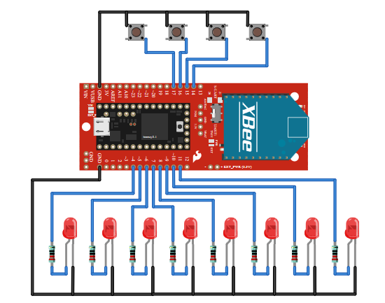
Use the outer holes to connect all manor of switches and sensors that you wish to read from the Teensy. This tutorial makes a controller, so buttons and LEDs are connected as shown in this diagram.
Configure the XBees
The XBees are shipped with a default configuration (see XBee documentation). Even if they work out of the box, you’ll be using the default IDs and will be suseptable to unseen XBees interfering with your system (because some other designer had the similar thought, “I’m the only one here, why not use the default IDs.”) Also, you can change other more advanced features once you’re familiar with the concepts.
The parameters used for these demos
- ID/PAN ID = A5F1 - This can be any 16 bit hex value used to identify your network. Make sure it is the same for both radios and unique in your area. A5F1 was randomly chosen for this guide. You can choose any ID for your network.
- Data rate = 9600
- Parity = N
- All others at factory default
Configuring XBees with USB based explorers
- Socket an XBee into the explorer matching the silkscreen orientation
- Plug the explorer into the USB port
- Open X-CTU
- Select your explorer’s serial port
- Querry the XBee to make sure the drivers are working
- Read the configuration from the XBee
- Modify the parameters
- Write the new configuration to the XBee
Repeat this process so that both XBees have the new configuration.
Power the System!
Apply to the system. Powering through the Teensy, use 3.7 to 5.5v. Alternately, supply regulated 3.3v to the EXT_PWER pins. Does the power LED on the adapter illumniated? It shows if power is getting to the XBee. Try running the blink sketch to determine if the Teensy is really powered and ready to recieve firmware.
Software
Working with your serial ports
Working with wireless devices is more difficult than just a single arduino because more than one serial port is in use. Where Arduino allows you to simply load the serial monitor to talk to your code, be extra careful remembering which ports what device and which terminal are using.
The first serial link in use is between the XBee and computer through the serial explorer. Get this port open and communicating to the XBee, then leave it alone. It ushers bytes you type into it into the air, and prints whatever comes into it’s antenna to your screen. When the system is fully functional, this terminal will tell you what buttons are being pressed.
The second serial link is the Arduino serial monitor, which connects to the Teensy over the USB cable. Eventually the Teensy will be disconnected from the computer but it can be usefull to get debugging information from your program while working with it. Be careful not to confuse it with the other serial ports. When you upload a sketch, the serial monitor automatically closes. If you’re using a 3rd party terminal here make sure it is closed before upload in order to free up the USB port for programming.
The trickest serial link in this project is the one that goes from the Teensy to the XBee because we have little information about it. Without expensive scopes, use the Din and Dout LEDs to monitor if there is activity from the Teensy to the XBee. One illumniates when the Teensy sends data to the XBee, and the other for showing when data is comming from the XBee to the Teensy.
Test your serial and XBee configuration
Two sketches are provided to ease bringing the XBees on line. They pass data between the XBee and the serial monitor using the HW UART or the SW UART ‘AltSoftSerial’ library. You can get them from the Github repository for the Teensy_3_1_XBee_Adapter or by copy-pasting from below
teensy_3_1_xbee_UART1_example
Note: Teensy board not currently supported by codebender
Set the adapter’s serial switch to UART1. Then, load and run the example. Open the serial monitor. Text entered in the serial monitor will be passed to the XBee, and come out the X-CTU (or other, I use Tera Term) serial monitor. Typing in that terminal will send the text back to the Arduino serial monitor. This tests the HW UART and XBee configurations
teensy_3_1_xbee_SUART_example
Note: Teensy board not currently supported by codebender
This sketch works much like the UART1 example but with the AltSoftSerial library, leaving the HW UART free to connect to other resources. Set the adapter’s switch to UART1 and run the sketch. Text should be passed between the two serial terminals.
Running the demo sketch
One sketch is provided to demonstrate passing data between a computer with SparkFun XBee Explorer USB and the Teensy with XBee. You can get it from the Github repository for the Teensy_3_1_XBee_Adapter or by copy-pasting from below
teensy_3_1_xbee_buttons_and_leds_example
Note: Teensy board not currently supported by codebender
This sketch demonstrates bi-directional communication and shows off operation that is more than just data echo.
Connections:
- Attach buttons to pins 14-17 of the Teensy, and to ground. The pins are pulled up inside the teensy and will float high until a button is depressed.
- Attach LEDs from pins 4-12 of the Teensy, through a current limiting resistor, to ground. It’s not so important to have all 8, 2 or 3 is enough to demonstrate the effect.
Each time the loop() runs, the sketch:
- Converts button presses to an ascii repersentation
- Prints the button states to the Arduino serial monitor
- Transmits the button states as a series of ascii characters
- Checks for received data from the XBee. If a number 1-8 is received, the associated LED on pins 14-21 is illuminated. If any other character is received, all 8 LEDs are are switched off.
Conclusion
The Teensy is really a great small-footprint powerhouse. Paired with the XBee you can get a great long distance serial connection, and with the 72MHz of processing speed (48MHz for the Teensy-LC) you can do a lot with the information. The Teensy is also capable of being a “class driver” device, you can get that data into a computer with ease, turning it into a keyboard, mouse, serial, or midi device.
Resources and Going Further
Here’s some links for getting extra information:
- Github repository for the Teensy_3_1_XBee_Adapter - Contains example code and hardware design of this product.
- PJRC(Teensy manufacturer) website - Documentation and resources by the Teensy Manufacturer.
- Service page for digi(XBee manufacturer) - Search for XBee product manuals
- IC manufacturer for Teensy MCUs - Get real dense datasheets and product documentation about the M0(MKL26Z64VFT4) and M4(MK20DX256VLH7) cortex cores.
learn.sparkfun.com |CC BY-SA 3.0 | SparkFun Electronics | Niwot, Colorado