Preassembled 40-pin Pi Wedge Hookup Guide a learn.sparkfun.com tutorial
Available online at: http://sfe.io/t432
Introduction
The preassembled 40-pin Pi Wedge is the newest member in our Pi Wedge family. It’s an excellent way to get those pesky Pi pins broken out to a breadboard so that they can easily be used.

The Pi Wedge in a breadboard
This Pi Wedge is compatible with members of the Pi family with 40-pin GPIO headers, including
- The Raspberry Pi Model A+
- The Raspberry Pi Model B+
- The Raspberry Pi 2 Model B
It adapts the 40-pin GPIO connector on recent Pis to a breadboard-friendly form factor and rearranges the pins by similar function. Also, the GPIO pins are arranged in ascending order.
This version also comes fully assembled – no soldering is required!

The Pi Wedge, shown with a Pi B+.
Covered in This Tutorial
- Background– How the Pi Wedge came to be
- Assembly– How to connect the FTDI, ribbon cable, and breadboard
- Pin Mapping– What the silkscreen on the Wedge represents
- Logic Levels and Power– Electrical information about connecting to the Pi
- Some additional resources
But before you begin, check out these links and brush up on topics you may not be familiar with:
Suggested Reading
Suggested Viewing
Background
In the process of developing projects like the Twitter Monitor and Great American Tweet Race around the Raspberry Pi, we found that we were experiencing some growing pains when trying to expand the Pi into a prototype that involved external hardware.

There’s a Pi somewhere in this ratsnest
The Raspberry Pi Model B+ has a 40-pin connector that provides access to several communication interfaces, plus GPIO and power. But the connector doesn’t have detailed labeling, and the native pin arrangement is somewhat scattershot. Pins used for similar functions aren’t always grouped together, and power and ground pins are interspersed with no obvious pattern.
The pins also don’t translate to a solderless breadboard very easily. Our first projects used a bunch of F-M jumper wires that we just plugged into the header. They involved a lot of “ratsnest jiggling” when things stopped working.
Bootstrapping
In addition to the physical issues of using the I/O connector, getting started with a brand new Raspberry Pi B+ always seems to involve a chicken-and-egg situation. We just want to SSH into it, so we can use the command line. But in order to SSH to it, we need to know it’s IP address…and of course, the IP address is most easily learned by running ifconfig on the command line.
The Solution
Meet the 40-Pin Pi Wedge
The Pi Wedge B+ connects to the 40-pin GPIO connector, and breaks out the pins in a breadboard-friendly arrangement and spacing. It adds a pair of decoupling capacitors on the power supply lines, and it makes the initial bringup process easier - you can plug an FTDI Basic module into the serial port.
Assembly
Contents
The Preassembleed Pi Wedge comes with the Wedge PCB, and a 40-pin ribbon cable.
Connection
The 40-pin ribbon cable is used to connect the wedge to the Pi. This cable is polarized. On the Pi Wedge PCB end, the tooth on the cable will interface with the notch in the shrouded header.

Inserting the ribbon cable
The header on the Pi B+ itself doesn’t have anything to help guarantee the alignment. You’ll need to take care that it gets connected properly. Pin 1 on the Pi is marked with a dog-eared corner on the silkscreened rectangle. The ribbon cable connector is embossed with (a barely visible) small triangle that marks pin 1. The first pin is also coded on the wire, such as the red markings in the photo below (though it may also be another color, such as black or dark blue).

Proper pin-1 orientation
The FTDI connector also needs to be aligned correctly. Be sure to match up the “grn” and “blk” markings on both boards.

Proper 3.3V FTDI-Basic orientation
In the next section, we’ll explore how the signals from the Pi are mapped to the Wedge.
Pin Mapping
Changes With the B+
When the Raspberry Pi foundation introduced the B+, they expanded the GPIO header from 26 to 40 pins. These changes have been carried forward by the A+ and Pi 2 Model B. The connector adds nine more GPIO pins plus the ID_SC and ID_SD pins to identify external peripherals, which you can learn more about in our SPI and I2C tutorial.
Signal Location
The Pi Wedge reorganizes the I/O pins on the Pi, putting similar functions on adjacent pins. The SPI, I2C and UART signals are all grouped near each other.

Functional Groupings
The pins are labeled, though the labels are short, to fit the space available on the PCB. The UART, SPI and I2C pins are marked with their communication bus functions, but they are also available as GPIO pins when configured in that mode.
The following table denotes the assignment of signals on the Pi Wedge, including the peripheral and alternate GPIO assignments where appropriate.
| Function | GPIO# | Function | GPIO# | |
| GPIO 17 | GPIO18 | |||
| GPIO 16 | GPIO19 | |||
| GPIO 13 | GPIO 20 | |||
| GPIO 12 | GPIO 21 | |||
| GPIO 6 | GPIO 22 | |||
| GPIO 5 | GPIO 23 | |||
| GPIO 4 | GPIO 24 | |||
| SPI CE 1 | GPIO 7 | GPIO 25 | ||
| SPI CE 0 | GPIO 8 | GPIO 26 | ||
| SPI MOSI | GPIO 10 | GPIO 27 | ||
| SPI MISO | GPIO 9 | SCL | GPIO 3 | |
| SPI CLK | GPIO 11 | SDA | GPIO 2 | |
| UART RXI | GPIO 15 | ID SC | GPIO 0 | |
| UART TXI | GPIO 14 | ID SD | GPIO 1 | |
| 5V | 5V | |||
| 3.3V | 3.3V | |||
| GROUND | GROUND |
Pi Wedge B+ Pin-Function mapping
Logic Levels And Power
Logic Levels
The Pi uses 3.3V logic levels, which are not 5V tolerant. Many peripheral devices are capable of running at 3.3V, but in the case that you need to interface with 5V devices, use a level shifter, such as the TXB0104 breakout.
Communications
The signals on the 6-pin FTDI header are also limited to 3.3V logic levels. Be sure to use it with a 3.3V FTDI module, and not a 5V one.
Power
Understanding the Pi’s power supply is critical to using it successfully, particularly when building it into a larger system.
The Raspberry Pi B+ is more efficient than it’s predecessors, as it replaces the former chain of linear power regulators with switching regulators.
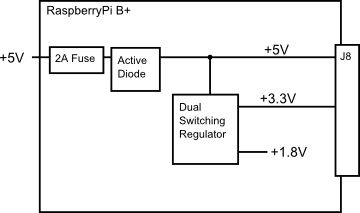
The most recently published schematics are for the Raspberry Pi B+, and we’re assuming that the Pi2 model B and A+ are similar. Inspecting those schematics, we see that 5V comes into the the board via connector J1 - it’s a micro USB connector, but only the power and ground pins are connected. The 5V coming from this connector passes through a fuse and a transistor circuit that protects against power polarity mishaps, then continues around the board without any further regulation. The 5V connections on the Pi Wedge come straight from this line.
On the B+, the 5V goes to a dual switching regulator that further reduces it to 3.3V, and 1.8V. The regulated 3.3V is present on the I/O connector.
There are several power strategies that can be applied in a Pi deployment, depending on the overall needs and availability.
Power Through the GPIO Connector
The most obvious strategy for powering small external circuits is to get power directly from the GPIO connector. To power small circuits on your breadboard, you can run jumpers from the 5V or 3.3V and Ground pins on the wedge to the power rails on the breadboard.

Jumpering power to the breadboard rails
While this is the most immediate way to access power, it only extends to small circuits. The B+ itself is limited to 2A total from the 5V line, most of which is needed by the B+ itself. The stated limit for the 3.3V pins is 50 mA.
If you’re developing external circuitry, and the Pi resets when you’re testing it, you may be exceeding the current limits. We saw this exact situation arise as we added SPI controlled 7-segment LED displays - if we illuminated one too many segments, the system crashed. For circuits with higher power draw, we’ll need to explore some alternatives.
Daisy Chaining
The next power option is to connect each section of the circuit directly to the power supply. This means that the peripherals aren’t constrained by the current limits of the fuses and regulators on the Pi itself.
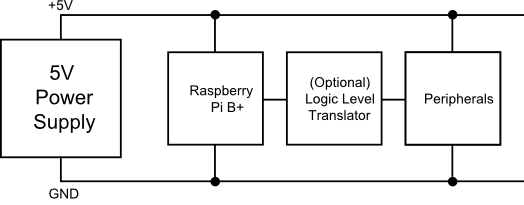
The peripherals are powered directly by the supply directly
For peripherals that use 5V logic, they should also include 3.3V/5V logic level translation.
Back Power Through J8
As described above, a simple deployment can power peripherals via the 5V and 3.3V pins of J8, but it’s also possible to apply power to the Pi via those lines. The Pi Foundation call this “back powering”, and they have a number of recommendations for it’s implementation.
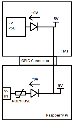
The first recommendation is to duplicate the fuse and MOSFET + BJT power protection circuit as seen on the Pi itself. This circuit is a variant on the “ideal diode” circuit.
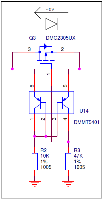
It serves several purposes:
- Under ordinary circumstances, with power coming in via the micro-USB plug, the MOSFET is biased fully on, so there is only minimal voltage drop across it, where a typical Schottky or Silicon diode would drop 0.3V or more.
- Second, it prevents power from flowing if the power polarity at the micro-USB plug is incorrect.
- Third, if the board is powered via J8, it prevents power from being drawn from J1, to prevent contention if two supplies are present at the same time.
The other recommendation is that the HAT needs to be able to provide 5V, +/- 5%, with at least 1.3 A available for the Pi.
Resources & Going Further
Going Further
If you want more detailed information about the Wedge and the interfaces it breaks out, check out the following materials:
- To take a closer look at programming for the I/O on a Pi, in both Python and C, take a look at our Raspberry gPIo tutorial.
- If you want to use the synchronous serial interface broken out by the wedge, you can learn more in out I2C & SPI tutorial
- The design files for the PCB, and some WiringPi software examples can be found in the 40-pin Pi Wedge GitHib repository.
Resources
For more information about the Raspberry Pi B+ and the software described here, please visit their sites.
- The Raspberry Pi Foundation
- The Pi Foundation’s B+ Addons forum.
- The Pi Foundation’s GitHub repository for the Raspberry Pi B+ HATs.
- The eLinux.org Raspberry Pi peripherals guide
- WiringPi
- RPi.GPIO module
- Some notes about increasing the available current from the B+ USB ports.
If you have any problems or questions, our technical support department can help. Please don’t hesitate to contact us. We also love to hear about your projects!
learn.sparkfun.com |CC BY-SA 3.0 | SparkFun Electronics | Niwot, Colorado