BadgerHack: Sensor Add-On Kit a learn.sparkfun.com tutorial
Available online at: http://sfe.io/t476
Introduction
The BadgerStick that you received by visiting a SparkFun booth at one of the various events we’ve attended can be hacked to perform a wide variety of tasks. The BadgerStick is a fully capable microcontroller that can sense the environment around it.
This tutorial will guide you through turning your BadgerStick into an environment sensing station. We’ll do so by adding a temperature sensor and a soil moisture sensor.
Plant not included
Required Materials
On top of your Badgerstick/Redstick and LED array display you will need a few more parts for this project:
Suggested Reading
Before starting this tutorial, we highly recommend you work through the main BadgerHack guide first.
BadgerHack
September 23, 2015
Additionally, if you are new to soldering or electronics, we recommend you check out the following:
When you are ready to start hacking your badge, we definitely recommend reading:
Hardware Hook-up
There is a little bit of soldering, so if you need a quick refresher on that I suggest taking a look at our soldering tutorial.
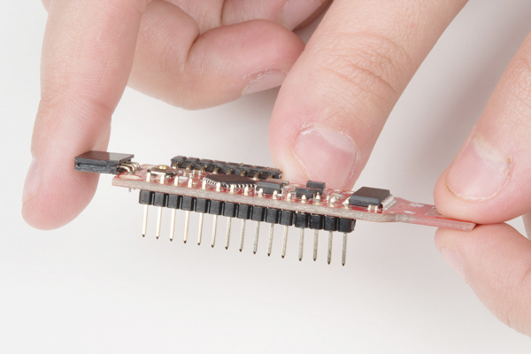
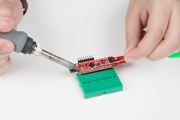
To begin, snap off 15 pins from the break-away headers, and solder them to the through-holes on the side opposite the LED array of the BadgerStick.
You can place the headers in the breadboard to help keep them in place as you solder.
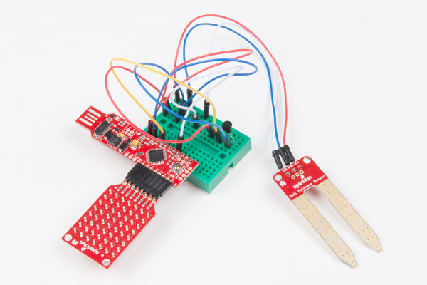
The rest of the setup will be using the breadboard and the jumper wires.
Start by sticking the headers you just soldered to your stick at a corner of your breadboard.
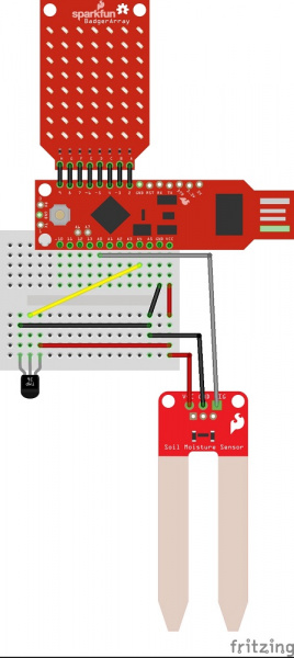
Now we will connect the sensors as follows:
| Component Pin | Badger/Redstick Pin | |||
|---|---|---|---|---|
| Soil Moisture Sensor VCC | VCC | |||
| Soil Moisture Sensor GND | GND | |||
| Soil Moisture Sensor SIG | A0 | |||
| Temperature Sensor left | GND | |||
| Temperature Sensor middle | A4 | |||
| Temperature Sensor right | VCC | |||
* Pins not listed are not used.
Here is a picture layout of how to connect everything up
Fritzing diagram of a RedStick hookup (GND and VCC slightly different on a BadgerStick).
With everything hooked up, it’s time to upload some code.
Code
Analog sensors work by providing a voltage output that is proportional to the what they are measuring. This means with something like analog temp sensor we are using, the output voltage can be converted to temperature easily using the scale factor of 10 mV/°C. However, a little bit of math is required depending on what the input voltage is, so that will change based on if you are using the Badgerstick at 3.3V or the Redstick at 5V. (But don’t worry, this has already been done for you in the code.)
The soil moisture sensor works the same way, but we are leaving the data as is, since converting it to something usable like kg of water per kg or soil would be very difficult without knowing what kind of soil you have and how it reacts to electricity.
Plug the USB side of your BadgerStick into your computer. Make sure “BadgerStick” and the associated COM port are selected in the window below. Click “Run on Arduino.”
If you have the Redstick Make sure “Arduino Uno” and the associated COM port are selected in the window below. Click “Run on Arduino.” Also if you are using a Redstick, you will need to go into the code and change one variable at the end to have the correct temp output (instructions in the code).
Resources and Going Further
With that, you should have an environment sensing station over which you have full control.
Like sensors? Here are a few more sensors that are pretty cool:
Resources
- BadgerStick GitHub repository
- BadgerArray GitHub repository
- BadgerHack Demos GitHub repository
- Codebender LED Array library
Other BadgerHack Projects
Check out some of the other things you can make with the Badger:
BadgerHack: Gaming Add-On Kit
February 16, 2016
learn.sparkfun.com |CC BY-SA 3.0 | SparkFun Electronics | Niwot, Colorado


