Flex Sensor Hookup Guide a learn.sparkfun.com tutorial
Available online at: http://sfe.io/t511
Introduction
This flex sensor is a variable resistor like no other. The resistance of the flex sensor increases as the body of the component bends. Sensors like these were used in the Nintendo Power Glove. They can also be used as door sensors, robot whisker sensors, or a primary component in creating sentient stuffed animals.

Flex sensors are available in two sizes: one 2.2" (5.588cm) long and another coming in at 4.5" (11.43cm) long.
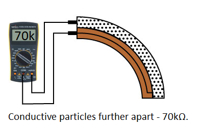
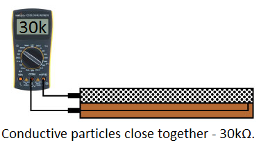
Left flat, these sensors will look like a 30kΩ resistor. As it bends, the resistance between the two terminals will increase to as much as 70kΩ at a 90° angle.
By combining the flex sensor with a static resistor to create a voltage divider, you can produce a variable voltage that can be read by a microcontroller’s analog-to-digital converter.
Suggested Materials
This tutorial serves as a quick primer on flex sensor’s, and demonstrates how to hook them up and use them. Aside from the sensor, the following materials are recommended:
Arduino Uno– We’ll be using the Arduino’s analog-to-digital converter to read in the variable resistance of the sensor. Any Arduino-compatible development platform – be it a RedBoard, Pro or Pro Mini– can substitute.
Resistor Kit– To turn the flex sensor’s variable resistance into a readable voltage, we’ll combine it with a static resistor to create a voltage divider. This resistor kit is handy for some trial-and-error testing to hone in on the most sensitive circuit possible.
Breadboard and Jumper Wires– The flex sensor’s terminals are breadboard-compatible. We’ll stick that and the resistor, then use the jumper wires to connect from breadboard to Arduino.


Suggested Reading
Analog components, like these flex sensor’s, are a great sensor-reading entry-point for beginners, but there are a few electronics concepts you should be familiar with. If any of these tutorial titles sound foreign to you, consider skimming through that content first.
Analog to Digital Conversion
Analog vs. Digital
Flex Sensor Overview
Before we get to circuit-building and Arduino-programming, here’s a quick rundown of the flex sensor’s important electrical characteristics.
How it Works
One side of the sensor is printed with a polymer ink that has conductive particles embedded in it. When the sensor is straight, the particles give the ink a resistance of about 30k Ohms. When the sensor is bent away from the ink, the conductive particles move further apart, increasing this resistance (to about 50k-70K Ohms when the sensor is bent to 90°, as in the diagram below).
When the sensor straightens out again, the resistance returns to the original value. By measuring the resistance, you can determine how much the sensor is being bent.
The flex sensor is designed to be flexed in just one direction – away from the ink – as demonstrated in the image below.

Flex sensor bend direction (from SpectraSymbol Datasheet).
Bending the sensor in the other direction will not produce any reliable data, and may damage the sensor. Also take care not to bend the sensor close to the base, as they have a tendency to kink and fail.
Example Circuit
The simplest way to incorporate this sensor into your project is by using it in a voltage divider. This circuit requires one resistor. Many values from 10KΩ to 100KΩ will work. If you have a resistor kit, you may want to introduce some trial-and-error to hone in on that perfect static resistance.
A value between the minimum and maximum resistance values is usually a good choice. We’ll use a 47kΩ resistor in this example. Here’s the hookup:

And a schematic:
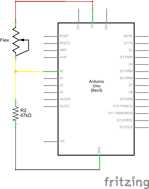
The 47kΩ resistor on the ground side, and the flex sensor on the 5V side, means as the flex sensor’s resistance increases (meaning the sensor is bending) the voltage on A0 will decrease.
Example Program
Here is a simple Arduino example based on the circuit above. Copy and paste this into your Arduino IDE (or use Codebender), then upload!
NOTE: For this example, we're hosting the code on codebender, which not only features code-sharing, but also allows anyone to upload and debug Arduino sketches from within a web browser. Plus, it works on lower-tech machines, like Chromebooks!
There are codebender plugins for Chrome, Chromium, and Firefox. Visit the codebender plugin page for help installing the codebender plugin.
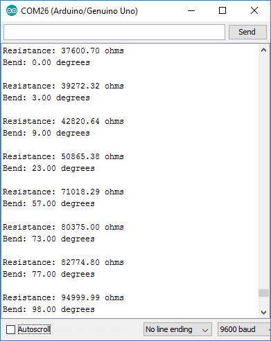
After uploading, open your serial monitor, and set the baud rate to 9600 bps. Or you can use the embedded serial monitor below.
If you bend the flex sensor, you should see resistance and estimated angle calculations change:
If the value’s don’t seem correct, make sure the constants VCC and, more importantly, R_DIV are accurate. If you used something other than a 47kΩ resistor, enter that value in for R_DIV.
Through trial-and-error, try to hone in on more accurate values for STRAIGHT_RESISTANCE and BEND_RESISTANCE– your flex sensor’s resistance when it’s straight and bent at 90°.
Resources and Going Further
Looking for more flex sensor related documentation? Here are a few sources you may want to consult:
Need some project inspiration? Want to check out some similar analog sensors? Check out some of these related tutorials:
SIK Keyboard Instrument
Sensor Kit Resource Hub
Force Sensitive Resistor Hookup Guide
learn.sparkfun.com |CC BY-SA 3.0 | SparkFun Electronics | Niwot, Colorado