Force Sensitive Resistor Hookup Guide a learn.sparkfun.com tutorial
Available online at: http://sfe.io/t510
Introduction
Force-sensitive resistor’s (FSR) are easy-to-use sensors designed for measuring the presence and relative magnitude of localized physical pressure.
The resistance of an FSR varies as the force on the sensor increases or decreases. When no pressure is being applied to the FSR, its resistance will be larger than 1MΩ. The harder you press on the sensor’s head, the lower the resistance between the two terminals drops. By combining the FSR with a static resistor to create a voltage divider, you can produce a variable voltage that can be read by a microcontroller’s analog-to-digital converter.
Suggested Materials
This tutorial serves as a quick primer on FSR’s and demonstrates how to hook them up and use them. Beyond an FSR of your choice, the following materials are recommended:
Arduino Uno– We’ll be using the Arduino’s analog-to-digital converter to read in the variable resistance of the FSR. Any Arduino-compatible development platform – be it a RedBoard, Pro or Pro Mini– can substitute.
Resistor Kit– To turn the FSR’s variable resistance into a readable voltage, we’ll combine it with a static resistor to create a voltage divider. This resistor kit is handy for some trial-and-error testing to hone in on the most sensitive circuit possible.
Breadboard and Jumper Wires– The FSR’s terminals are breadboard-compatible. We’ll stick in that and the resistor, then use the jumper wires to connect from breadboard to Arduino.


Suggested Reading
Analog components, like these FSRs, are a great sensor-reading entry-point for beginners, but there are a few electronics concepts you should be familiar with. If any of these tutorial titles sound foreign to you, consider skimming through that content first.
Analog to Digital Conversion
Analog vs. Digital
FSR Overview
There are a variety of FSR options out there, and a few key characteristics to differentiate them: size, shape, and sensing range. Here’s a quick overview:
| Name | Shape | Sensing Area | Min Pressure | Max Pressure |
|---|---|---|---|---|
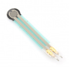 Force Sensitive Resistor - Small (SEN-09673) | Circular | 7.62 mm dia (0.3 in) | 0.1 kg (0.22 lb) | 1 kg (2.2 lb) |
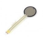 Force Sensitive Resistor 0.5" (SEN-09375) | Circular | 12.7 mm dia (0.5 in) | 100 g (0.22 lb) | 10 kg (22.04 lb) |
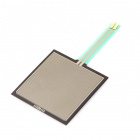 Force Sensitive Resistor - Square (SEN-09376) | Square | 44.45 x 44.45 mm (1.75 x 1.75 in) | 100 g (0.22 lb) | 10 kg (22.04 lb) |
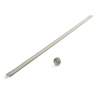 Force Sensitive Resistor - Long (SEN-09674) | Rectangular | 6.35 x 609.6 mm dia (0.25 x 24.0 in) | 100 g (0.22 lb) | 10 kg (22.04 lb) |
Shape and Size
Most FSR’s feature either a circular or rectangular sensing area. The square FSR is good for broad-area sensing, while the smaller circular sensors can provide more precision to the location being sensed.
The rectangular FSR’s include a small-ish square 1.75 x 1.75" sensor and a long 0.25 x 24" strip. The rest of the sensors feature a circular sensing area.
Sensing Range
Another key characteristic of the FSR is it’s rated sensing range, which defines the minimum and maximum amounts of pressure that the sensor can differentiate between.
The lower the force rating, the more sensitive your FSR hookup has the potential to be. But! Any pressure beyond the sensor’s maximum limit will be unmeasurable (and may damage the component). The small 1kg-rated FSR will provide more sensitive readings from 0 to 1kg, but won’t be able to tell the difference between a 2kg and 10kg weight.
Force vs. Resistance
The graph below, figure 2 from the FSR Integration Guide, demonstrates the typical force-resistance relationship:

The relationship is generally linear from 50g and up, but note what the relationship does below 50g, and even more-so below 20g. These sensor’s have a turn-on threshold– a force that must be present before the resistance drops to a value below 10kΩ, where the relationship becomes more linear.
Example Hardware Hookup
By creating a voltage divider with the FSR and another resistor, you can create a variable voltage output, which can be read by a microcontroller’s ADC input.
Selecting a Static Resistor
The tricky part of voltage-dividing an FSR is selecting a static resistor value to pair with it. You don’t want to overpower the maximum resistance of the FSR, but you also don’t want the FSR’s minimum resistance to be completely overshadowed either.
It helps to know what range of force you’ll be reading. If your project’s force-sensing covers the broad range of the FSR (e.g. 0.1-10kg), try to pick a static resistance in the middle-range of the FSR’s resistive output – something in the middle of 200-6kΩ. 3kΩ, or a common resistor like 3.3kΩ, is a good place to start.
Short on resistors? If all you have is 10kΩ resistors (looking at you Sensor Kit visitors), you can still make something close to 3k! Try putting three 10kΩ's in parallel to create a 3.33kΩ monster resistor. Or put three 330Ω resistors in series to create a 990Ω concoction, which will work pretty well too.
Example Circuit
Here’s a fritzing diagram combining the FSR, 3.3kΩ resistor, three jumper wires and the Arduino:

And the schematic:

This voltage divider will cause the voltage at A0 to increase as the resistance of the FSR decreases. When the FSR is left untouched, measuring as nearly an open circuit, the voltage at A0 should be zero. If you press as hard as possible on the FSR, the voltage should increase close 5V.
Example Arduino Sketch
Here is a simple Arduino example based on the circuit above. Copy and paste this into your Arduino IDE (or use Codebender), then upload!
NOTE: For this example, we're hosting the code on codebender, which not only features code-sharing, but also allows anyone to upload and debug Arduino sketches from within a web browser. Plus, it works on lower-tech machines, like Chromebooks!
There are codebender plugins for Chrome, Chromium, and Firefox. Visit the codebender plugin page for help installing the codebender plugin.
After uploading, open your serial monitor, and set the baud rate to 9600 bps. Or you can use the embedded serial monitor below.
If you apply pressure to the FSR, you should see resistance and estimated pressure calculations begin to appear:
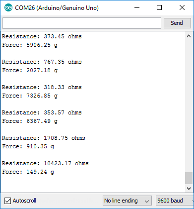
Play with the circuit and see how high or low you can get the readings to be. If you have more resistors, try swapping larger or smaller values in for the 3.3kΩ to see if you can make the circuit more sensitive. Don’t forget to change the value of R_DIV towards the top of the sketch if you do!
Resources and Going Further
Now that you’ve got a force-sensing Arduino circuit, what project are you going to create? If you need more FSR-related resources, be sure to check out the FSR Integration Guide, which goes in-depth on the sensor’s characteristics. The guide also presents a few more complex circuits you can try hooking up to get even more sensitivity out of your FSR.
Check out the FSR Integration Guide
Need some project inspiration? Want to check out some similar analog sensors? Check out some of these related tutorials:
SIK Keyboard Instrument
Sensor Kit Resource Hub
Flex Sensor Hookup Guide
learn.sparkfun.com |CC BY-SA 3.0 | SparkFun Electronics | Niwot, Colorado