Photocell Hookup Guide a learn.sparkfun.com tutorial
Available online at: http://sfe.io/t512
Introduction
Photocell’s are light-sensitive, variable resistors. As more light shines of the sensor’s head, the resistance between its two terminals decreases. They’re easy-to-use, and an essential component in projects that require ambient-light sensing.

In pitch-black conditions, the photocell’s resistance will be in the megaohm’s (1.0MΩ+) range. Shining an LED on the sensor can drop the resistance to near-zero, but usually the resistance of the photocell falls between 8-20kΩ in normal lighting conditions.
By combining the photocell with a static resistor to create a voltage divider, you can produce a variable voltage that can be read by a microcontroller’s analog-to-digital converter.
Suggested Materials
This tutorial serves as a quick primer on resistive photocells’s, and demonstrates how to hook them up and use them. Beyond the light sensor, the following materials are recommended:
Arduino Uno– We’ll be using the Arduino’s analog-to-digital converter to read in the variable resistance of the photocell. Any Arduino-compatible development platform – be it a RedBoard, Pro or Pro Mini– can substitute.
Resistor Kit– To turn the photocell’s variable resistance into a readable voltage, we’ll combine it with a static resistor to create a voltage divider. This resistor kit is handy for some trial-and-error testing to hone in on the most sensitive circuit possible.
Breadboard and Jumper Wires– The photocell’s legs, like any through-hole resistor, can be bent and shaped to fit. We’ll stick them and the resistor into a breadboard, then use the jumper wires to connect from breadboard to Arduino.


Suggested Reading
Photocells are a great entry-level component for beginners, but there are still a few basic electronics concepts you should be familiar with. If any of these tutorial titles sound foreign to you, consider skimming through that content first.
Light
Analog to Digital Conversion
Analog vs. Digital
Photocell Overview
The photocell, sometimes referred to as a photoresistor or light-dependent resistor (LDR), is a two-terminal, resistive component that increases or decreases its resistance depending on the light it senses. They’re available in a variety of shapes, sizes, and form factors; the mini photocell in our catalog features a 5x4.3mm head, and through-hole legs that can be soldered into a PCB or inserted into a breadboard.

In pitch black conditions, the resistance of most photocells will measure in the megaohms range. The typical light resistance of photocells varies by component. The mini photocell, for example, usually produces a resistance between 8-20kΩ in normal lighting conditions.
The graph below demonstrates the mini photocell’s illumination and resistance relationship:

Light vs. Resistance graph from the mini photocell datasheet.
As you can tell from the graph above, these sensor’s aren’t designed for absolute lux-measurement accuracy – they leave a lot of room for interpretation. But, by measuring the photocell’s resistance, they can provide a relative idea of a room’s lighting conditions, or tell us if the sun has risen or set.
Example Circuit
To measure the photocell’s resistance with a microcontroller’s ADC, we actually have to use it to generate a variable voltage. By combining the photocell with a static resistor, we can create a voltage divider that produces a voltage dependent on the photocell’s resistance.
A static resistor value between 1kΩ and 10kΩ should pair well with the photocell. If you have a resistor kit, you may want to introduce some trial-and-error to hone in on that perfect static resistance.
In this example, we’ll use a 4.7kΩ resistor to divide voltage with the photocell. Here’s the example circuit:

And a schematic:

The 4.7kΩ resistor on the ground side, and the photocell on the 5V side, means as the cell’s resistance increases (meaning the sensor’s surroundings are getting darker) the voltage on A0 will decrease.
Example Program
Here is a simple Arduino example based on the circuit above. Copy and paste this into your Arduino IDE (or use Codebender), then upload!
NOTE: For this example, we're hosting the code on codebender, which not only features code-sharing, but also allows anyone to upload and debug Arduino sketches from within a web browser. Plus, it works on lower-tech machines, like Chromebooks!
There are codebender plugins for Chrome, Chromium, and Firefox. Visit the codebender plugin page for help installing the codebender plugin.
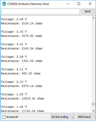
After uploading, open your serial monitor, and set the baud rate to 9600 bps. Or, you can use the embedded serial monitor below.
Then trigger some changes in light; cover the photocell with your hand, turn your lights off, or shine a flashlight on the cell. You should see the voltage and resistance calculations vary with the light. If it gets darker, the resistance should go up. If it gets lighter, the resistance should go down.
R_DIV variable at the top of the sketch is set to your static resistor's value.When the sensed light gets too dark, the Arduino should turn on the pin 13 LED to try to brighten things up. By adjusting the DARK_THRESHOLD variable, you can change what lighting conditions trigger this LED illumination.
Going Further
Now that you’ve got your Arduino reacting to ambient lighting conditions, what light-dependent project are you going to create? Need some inspiration? Check out some of these SparkFun tutorials:
Pushing Data to Data.SparkFun.com
SparkFun Inventor's Kit for MicroView
LilyPad Light Sensor Hookup Guide
Blynk Board Project Guide
learn.sparkfun.com |CC BY-SA 3.0 | SparkFun Electronics | Niwot, Colorado