9DoF Sensor Stick Hookup Guide a learn.sparkfun.com tutorial
Available online at: http://sfe.io/t542
Introduction
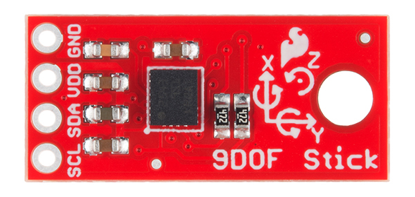
The 9DoF Sensor Stick is an easy-to-use 9 degrees of freedom IMU. The sensor used is the LSM9DS1, the same sensor used in the SparkFun 9 Degrees of Freedom IMU Breakout, but is slimmed down to be only 0.9"x0.4".
Required Materials
To follow along with this hookup guide, you will need the following:
Suggested Reading
Before getting started, you may find the following links useful:
- I2C Protocol
- Logic Levels
- Installing an Arduino Library
- What are Pull-up Resistors?
- How to use a Breadbaord
- Accelerometer Basics
- Gyroscope Basics
Board Overview
Let’s go over the 9DoF Sensor Stick in detail.
LSM9DS1 Details:
- 3 acceleration channels, 3 angular rate channels, 3 magnetic field channels
- ±2/±4/±8/±16 g linear acceleration full scale
- ±4/±8/±12/±16 gauss magnetic full scale
- ±245/±500/±2000 dps angular rate full scale
- I2C serial interface
- Operating Voltage: 3.3V
Pull-up Resistors
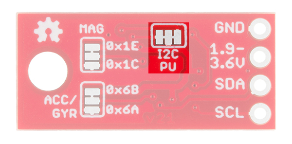
This breakout board has built-in 4.7 kΩ pull up resistors for I2C communications. If you’re hooking up multiple I2C devices on the same bus, you may want to disable/enable the pull-up resistors for one or more boards. On the 9DoF Sensor Stick, the pull-ups are enabled by default. To disable them, simply use a hobby knife to cut the traces connecting the left and right pads of the jumper labeled I2C PU on the back of the board. This will disconnect the resistors on the I2C bus from VCC.
Changing I2C Addresses
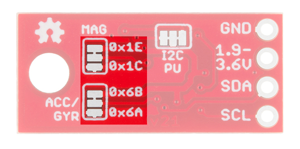
If you’re using multiple Sensor Sticks, or have a device that’s already using the default addresses of the Sensor Stick, you’ll want to change addresses to avoid having multiple devices try to talk over one another. The default address for the magnetometer is 0x1E and the default address for the accelerometer and gyroscope is 0x6B. To change the addresses, you’ll want to use a hobby knife to cut the trace between center and top pads and use solder to short the center and bottom pads. This will change the address of the magnetometer to 0x1C and the accelerometer and gyroscope to 0x6A.
Hardware Connections
Connecting the 9DoF Sensor Stick to an Arduino
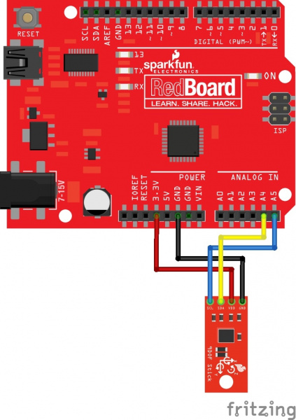
Wiring the Sensor Stick is very easy! We recommend soldering four male headers to the sensor stick. You can also directly solder wires to the board to fit your application’s needs.
Power
This board runs on 1.9V to 3.6V. Be sure to power the board from the 3.3V pin! I2C uses an open drain signaling, so there is no need to use level shifting; the 3.3V signal will work to communicate with the Arduino and will not exceed the maximum voltage rating of the pins on the LSM9DS1.
Connections to the Arduino
The 9DoF Sensor Stick has only four pins. We’ll be connecting VCC and GND to the normal power pins, and the remaining two pins are used for I2C communication. If you’re using a newer board that has SDA and SCL broken out, you can connect the SDA and SCL pins from the Sensor Stick directly to those pins. If you’re using an older board, SDA and SCL are pins A4 and A5 respectively.
- VCC → 3.3V
- GND → GND
- SDA → SDA/A4
- SCL → SCL/A5
Your circuit should look something like this:
Installing the Arduino Library
We’ve written a full-featured Arduino library to help make interfacing with the LSM9DS1’s gyro, accelerometer, and magnetometer as easy-as-possible. Visit the GitHub repository to download the most recent version of the library, or click the link below:
Download the SparkFun LSM9DS1 Arduino Library
For help installing the library, check out our How To Install An Arduino Library tutorial. You need to move the SparkFun_LSM9DS1_Arduino_Library folder into a libraries folder within your Arduino sketchbook or use the Library Manger to install.
The LSM9DS1_Basic_I2C Example
To verify that your hookup works, load up the LSM9DS1_Basic_I2C example by going to File>Examples>LSM9DS1 Breakout>LSM9DS1_Basic_I2C.
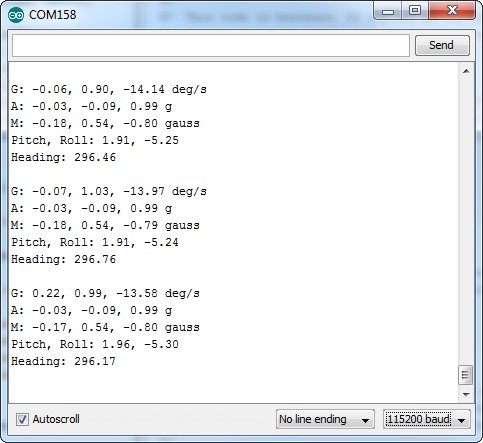
The default values set by this sketch should work for a fresh, out-of-the-box 9DoF Sensor Stick – it assumes both of the address jumpers haven’t been modified. Upload the sketch, then open up your serial monitor, setting the baud rate to 115200. You should see something like this:
The current reading from each axis on each sensor is printed out, then those values are used to estimate the sensor’s orientation. Pitch is the angle rotated around the y-axis, roll is the board’s rotation around the x-axis, and heading (i.e. yaw) is the sensor’s rotation around the z-axis. Try rotating the board (without pulling out any wires!) to see how the values change.
Resources and Going Further
For more information about the 9DoF Sensor Stick, check out the links below:
- LSM9DS1 Datasheet– This datasheet covers everything from the hardware and pinout of the IC, to the register mapping of the gyroscope and accelerometer/magnetometer.
- 9DoF Sensor Stick GitHub Repository– Your revision-controlled source for the 9DoF Sensor Stick. Here you’ll find our most up-to-date hardware layouts and code.
- 9DoF Sensor Stick Schematic
- 9DoF Sensor Stick EAGLE Files
Going Further
Now that you’ve got the Sensor Stick up-and-running, what project are you going to incorporate motion-sensing into? Need a little inspiration? Check out some of these tutorials!
- Dungeons and Dragons Dice Gauntlet– This project uses an accelerometer to sense a “rolling the dice” motion. You could swap in the LSM9DS1 to add more functionality – like compass-based damage multipliers!
- Are You Okay? Widget– Use an Electric Imp and accelerometer to create an “Are You OK” widget. A cozy piece of technology your friend or loved one can nudge to let you know they’re OK from half-a-world away.
- Leap Motion Teardown– An IMU sensor is cool, but image-based motion sensing is the future. Check out this teardown of the miniature-Kinect-like Leap Motion!
- Pushing Data to Data.SparkFun.com– Need an online place to store your IMU data? Check out data.sparkfun.com! This tutorial demonstrates how to use a handful of Arduino shields to post your data online.
Creating a Humidor Control Box
Internet Datalogging With Arduino and XBee WiFi
Wake-on-Shake Hookup Guide
Blynk Board Washer/Dryer Alarm
learn.sparkfun.com |CC BY-SA 3.0 | SparkFun Electronics | Niwot, Colorado

