12V/5V Power Supply Hookup Guide a learn.sparkfun.com tutorial
Available online at: http://sfe.io/t777
Introduction
The 12V/5V (2A) power supply is great for powering a microcontroller and an LEDs. In this tutorial, we will replace the power supply’s molex connector with two male barrel jacks adapters.

Required Materials
To follow along with this tutorial, you will need the following materials. You may not need everything though depending on what you have. Add it to your cart, read through the guide, and adjust the cart as necessary.
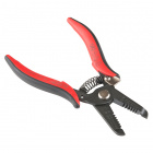
Tools
You will need a soldering iron, solder, general soldering accessories, and the following tools.


Suggested Reading
If you aren’t familiar with the following concepts, we recommend checking out these tutorials before continuing.
How to Solder: Through-Hole Soldering
Connector Basics
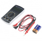
How to Use a Multimeter
Hardware Overview
The power supply’s pinout is shown below. The connector’s molding will have numbers associated with the output to help identify the connection. You will also notice that the connector is polarized with the two chamfered corners.

Pinout Table
The following table describes the molex connector’s pinout and what color the wire may look like.
| Molex Pinout | 12V/5V Power Supply | Notes |
|---|---|---|
| 1 | +12V | "Red" |
| 2 | N/C | May Not Be Not Connected |
| 3 | GND | "Yellow" |
| 4 | +5V | "Black (or White)" |
Hardware Hookup
Cut the cable about 1-2 inches from the molex connector.

Cut into sheath with the flush cutter. Pull it back just enough so that you have enough room to work with the wires. Be careful not to cut yourself!

Strip the power supply’s three wires. The wires are stranded so feel free to tin the wires by adding solder to the tips.

Then cut and strip a piece of hookup wire. Solder it to the ground wire.

Braid the wire and insert into a barrel jack connector. Secure the wires in the screw terminal with a Phillips head. Feel free to add some heat shrink or electrical tape to the connection at this point.

Test the Output
Power the power supply and test with a multimeter to verify the voltages. Usually power supplies are center positive so make sure that the wires were inserted correctly. Adjust as a necessary for your system.

Label the Output
Using a Sharpie, clearly label the barrel jack connector’s voltage relative to the output. Feel free to add an additional barrel jack when not in use.

Power Your Circuit!
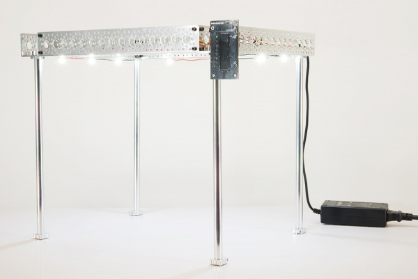
Connect the power supply to your circuit and power it up! I personally use the power supply as a tool for basic testing. Usually the 12V side is connected to an Arduino’s barrel jack. The 5V output is used for more power hungry loads such as the the RGB LED Matrix or a few meters of addressable (WS2812B, APA102, etc) LEDs.

Arduino Mega 2560 and 32x64 RGB LED Matrix Powered by the 12V/5V Power Supply
Troubleshooting
Certain power supplies have a lot of noise. While 12V/5V power supply works great with a microcontroller and a LED strip, it may not work as well when you attach a capacitive touch sensor to the system. The power supply lacks proper filtering and causes the potentiometer to have a lot of latency. You can try to add additional circuitry to fix it since the current power supply has a lot of noise. However, it would be easier to use two separate power supplies or a more robust power supply such as a Meanwell.
Example PWM Lighting Controller from the Touch Potentiometer Hookup Guide
Resources and Going Further
Now that you’ve successfully got your 12V/5V power supply up and running, it’s time to incorporate it into your own project!
For more information, check out the resources below:
- Molex Connector Pinout - Pinout of one power supply. Remember, wire color may vary depending on your manufacturer.
- Wikipedia: Molex Connector
- SparkFun Eagle Libraries - Check out the Eagle part for the molex connector in our libraries.
Need some inspiration for your next project? Check out some of these related tutorials that uses the 12V/5V (2A) power supply.
RGB Panel Hookup Guide
Large Digit Driver Hookup Guide
How to Build a Remote Kill Switch
Or check out some of these blog posts about power supplies
learn.sparkfun.com | CC BY-SA 3.0 | SparkFun Electronics | Niwot, Colorado