Qwiic Single Relay Hookup Guide a learn.sparkfun.com tutorial
Available online at: http://sfe.io/t832
Introduction
The Qwiic Single Relay is SparkFun’s easiest to use relay yet. The single relay can handle up to 5.5A at 240 VAC for long periods of time. The Qwiic connectors and screw terminals also mean that no soldering is necessary.

Required Materials
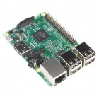
To get started, you’ll need a microcontroller to control everything. You may not need everything though depending on what you have. Add it to your cart, read through the guide, and adjust the cart as necessary.

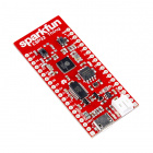
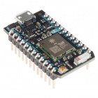
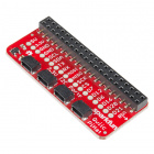
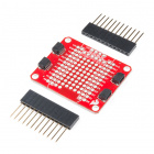
Now to get into the Qwiic ecosystem, the key will be one of the following Qwiic shields to match your preference of microcontroller:

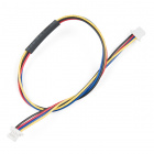
You will also need a Qwiic cable to connect the shield to your Qwiic Single Relay, choose a length that suits your needs.


Tools
You will need a flush cutter and wire stripper to remove the sheath and insulation from a cable. A Phillips head screwdriver will be required to connect the load's to a screw terminal.


Suggested Reading
If you aren’t familiar with the Qwiic system, we recommend reading here for an overview.
| Qwiic Connect System |
We would also recommend taking a look at the following tutorials if you aren’t familiar with them.
Serial Communication
Serial Terminal Basics
Qwiic Shield for Arduino & Photon Hookup Guide
Hardware Overview
First let’s check out some of the characteristics listed in the relay's datasheet that we’re dealing with, so we know what to expect out of the board.
| Characteristic | Range |
|---|---|
| Operating Voltage | 1.7V-3.6V |
| Supply Current | UPDATE |
| Coil Resistance | 23.5Ω |
| I2C Address | 0x18 (Default), (Jumper changes to 0x19) |
| Max Current (Through Relay) | 5.5A (240 VAC) |
Pins
The following table lists all of the relay’s pins and their functionality.
| Pin | Description | Direction |
|---|---|---|
| GND | Ground | In |
| 3.3V | Power | In |
| SDA | Data | Bi-directional |
| SCL | Clock | In |
| NC | Normally Closed | Switch |
| NO | Normally Open | Switch |
| COM | Switch Common | Switch |
Optional Features
The Qwiic Relay has pull up resistors attached to the I2C bus; if multiple sensors are connected to the bus with the pull-up resistors enabled, the parallel equivalent resistance will create too strong of a pull-up for the bus to operate correctly. As a general rule of thumb, disable all but one pair of pull-up resistors if multiple devices are connected to the bus. If you need to disconnect the pull up resistors they can be removed by cutting the traces on the corresponding jumpers highlighted below.

Pull-up Jumper
The Power LED will light up when the board is powered. The Status LED will light up when the relay has been triggered and the switch is closed, both are highlighted in the below image
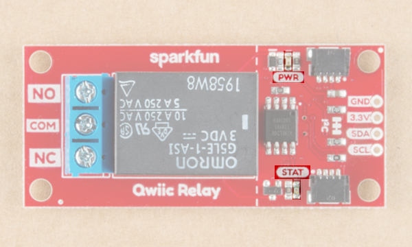
Power LED
The onboard screw terminal should be used to connect your high-power load, it is highlighted below. The middle COM pin should be hooked up to the Live wire (Usually black) coming from the wall, while NO or NC should be connected to the Live wire on the device side of things.

Screw Terminal
Hardware Assembly
If you haven’t yet assembled your Qwiic Shield, now would be the time to head on over to that tutorial. Depending on the microcontroller and shield you’ve chosen, your assembly may be different, but here’s a handy link to the Qwiic Shield for Arduino and Photon Hookup Guide to get you started!
Qwiic Shield for Arduino Photon Hookup Guide
With the shield assembled, SparkFun’s new Qwiic environment means that connecting the relay could not be easier. Just plug one end of the Qwiic cable into the Qwiic Relay, the other into the Qwiic Shield and you’ll be ready to upload a sketch and start turning things on and off. It seems like it’s too easy too use, but that’s why we made it that way!

SparkFun RedBoard and Qwiic Shield with the Qwiic Relay attached
You’ll also need to place the relay in line with the AC powered item you’re attempting to control. You’ll have to cut your live AC line (usually black or red) and connect one end of the cut wire to COM and the other to NC or NO, depending on what you want the resting state of your device to be. If your AC device is going to be on for most of the time, and you occasionally want to turn it off, you should connect one end to COM and the other to NC. Connect to NO if the device will be off for most of the time. Check out the picture below for a visual aid.

Relay Example Connection
Looking for information about safety and insulation? Check out the notes about Safety and Insulation from our Beefcake Relay Control Kit.
Example Code
The Qwiic Relay is pretty simple, so all of the functions to control it are simply contained in the examples, which can be downloaded from the GitHub repo by clicking the button below.
Example 1 - Basic Control
Go ahead and unzip the folder to a directory of your choosing and open up Example1-Basic_control. In this example, we’ll simply have the relay toggle on for 2 seconds, then off for two seconds. Let’s first look at the available functions in our sketch. The first two, relayOn() and relayOff(), are pretty self explanatory, they toggle the relay and return a message to the Serial monitor if no slave is found . The testForConnectivity() function simply tests to see if there is a slave at the proper address (0x18). These functions can be found below.
language:c
void relayOn() {
  Wire.beginTransmission(qwiicRelayAddress);
  Wire.write(COMMAND_RELAY_ON);
  if (Wire.endTransmission() != 0) {
    Serial.println("Check Connections. No slave attached.");
  }
}

void relayOff() {
  Wire.beginTransmission(qwiicRelayAddress);
  Wire.write(COMMAND_RELAY_OFF);
  if (Wire.endTransmission() != 0) {
    Serial.println("Check Connections. No slave attached.");
  }
}

void testForConnectivity() {
  Wire.beginTransmission(qwiicRelayAddress);
  //check here for an ACK from the slave, if no ack don't allow change?
  if (Wire.endTransmission() != 0) {
    Serial.println("Check Connections. No slave attached.");
    while (1);
  }
}
Now that we have these functions declared (Arduino handles prototype declarations for us), we can use them in our void setup() and void loop(). In our setup() function, we simply use the testForConnectivity() function to do just that. We then move on the void loop() where we turn the relay on, wait 2 seconds, turn the relay off, wait two seconds, and repeat. This code from Example 1 is shown below.
language:c
void setup() {
  Serial.begin(9600);
  Serial.println("Qwiic Relay Example 1 Basic Control");
  Wire.begin(); // join the I2C Bus

  testForConnectivity();

}

void loop() {
  relayOn();
  Serial.println("Relay is On.");
  delay(2000);
  relayOff();
  Serial.println("Relay is Off.");
  delay(2000);
}
Opening your serial monitor to a baud rate of 9600 should show something similar to the output below if everything is connected properly. You should also be able to hear the relay clicking on and off. If things aren’t connected properly, you’ll see the message Check connections. No slave attached..

Example 1 Output
Example 2 - Change I2C Address
To get started with the second example, open up Example2-Change_I2C_Address In this example, we simply change the address to 0x19. First, let’s take a look at the changeAddress() function, which checks to see if the address is valid (Between 0x07 and 0x78) and changes the relay’s address to that. The function returns true if successful.
language:c
boolean changeAddress(byte address) {
  Wire.beginTransmission(qwiicRelayAddress);
  //check here for an ACK from the slave
  if (Wire.endTransmission()  != 0) {
    Serial.println("Check Connections. No slave found.");
    return (false);
  }

  //check if valid address.
  if (address < 0x07 || address > 0x78) {
    Serial.println("Invalid I2C address");
    return (false);
  }
  //valid address
  Wire.beginTransmission(qwiicRelayAddress);
  Wire.write(COMMAND_CHANGE_ADDRESS);
  qwiicRelayAddress = address;
  Wire.write(qwiicRelayAddress);
  Wire.endTransmission();
  return (true); //Success!
}
Now that we have these functions declared (Arduino handles prototype declarations for us), we can use them in our void setup() and void loop(). In our setup() function, we change the address to 0x19, check to see that the address change was a success, and toggle the relay on and off on this new address. The sketch that handles this is shown below.
language:c
#include <Wire.h>
#define COMMAND_RELAY_OFF                 0x00
#define COMMAND_RELAY_ON                    0x01
#define COMMAND_CHANGE_ADDRESS          0x03

volatile byte qwiicRelayAddress = 0x18;     //Default Address

void setup() {
  Serial.begin(9600);
  Serial.println("Qwiic Relay Master Awake");
  Wire.begin(); // join the I2C Bus

  Wire.beginTransmission(qwiicRelayAddress); // transmit to device
  //check here for an ACK from the slave
  if (Wire.endTransmission() != 0 ) {
    Serial.println("Check Connections. Slave not found.");
  }
  else {
    Serial.println("Qwiic Relay found!");
  }

  boolean error = changeAddress(0x19); // Change the Relay's address to 0x19

  if (error != true) {
    Serial.println("!!!!! invalid address" );
  }
  else {
    Serial.println("success");
  }
}

void loop() { //Toggle the Relay on the new address
  relayOn();
  delay(2000);
  relayOff();
  delay(2000);
}

// changeAddress() takes a 7 bit I2C Address
// and writes it to the Relay. This function
// checks to see if the address is between
// 0x07 and 0x78. If valid, the new address is
// saved to the Relay's EEPROM. If not valid
// address is not changed and is ignored.
// This function returns true if successful and
// false if unsuccessful.
boolean changeAddress(byte address) {
  //check if valid address.
  if (address < 0x07 || address > 0x78) {
    Serial.println("Invalid I2C address");
    return (false);
  }
  //valid address
  Wire.beginTransmission(qwiicRelayAddress);
  Wire.write(COMMAND_CHANGE_ADDRESS);
  qwiicRelayAddress = address;
  Wire.write(qwiicRelayAddress);
  if (Wire.endTransmission() != 0)
  {
    return false;
  }
  return true;
}

// RelayOn() turns on the relay at the SLAVE_ADDRESS
// Checks to see if a slave is connected and prints a
// message to the Serial Monitor if no slave found.
void relayOn() {
  Wire.beginTransmission(qwiicRelayAddress);
  Wire.write(COMMAND_RELAY_ON);
  if (Wire.endTransmission() != 0) {
    Serial.println("Check Connections. No slave attached");
  }
}

// RelayOff() turns off the relay at the qwiicRelayAddress
// Checks to see if a slave is connected and prints a
// message to the Serial Monitor if no slave found.
void relayOff() {
  Wire.beginTransmission(qwiicRelayAddress);
  Wire.write(COMMAND_RELAY_OFF);
  if (Wire.endTransmission() != 0) {
    Serial.println("Check Connections. No slave attached");
  }
}
Example 3 - I2C Scanner
To get started with the third example, open up Example3-I2C_Scanner In this example, we simply scan the I2C bus for devices, useful if we’ve been changing around the address of our relay and have since forgotten what it was. The example comes from Arduino, and the code can be shown below. We basically check for an ACK at each address, and output that address when we get one back.
language:c
#include <Wire.h>

void setup()
{
  Wire.begin();

  Serial.begin(9600);
  while (!Serial);             // Leonardo: wait for serial monitor
  Serial.println("\nI2C Scanner");
}


void loop()
{
  byte error, address;
  int nDevices;

  Serial.println("Scanning...");

  nDevices = 0;
  for (address = 1; address < 127; address++ )
  {
    // The i2c_scanner uses the return value of
    // the Write.endTransmission to see if
    // a device did acknowledge to the address.
    Wire.beginTransmission(address);
    error = Wire.endTransmission();

    if (error == 0)
    {
      Serial.print("I2C device found at address 0x");
      if (address < 16)
        Serial.print("0");
      Serial.print(address, HEX);
      Serial.println("  !");

      nDevices++;
    }
    else if (error == 4)
    {
      Serial.print("Unknown error at address 0x");
      if (address < 16)
        Serial.print("0");
      Serial.println(address, HEX);
    }
  }
  if (nDevices == 0)
    Serial.println("No I2C devices found\n");
  else
    Serial.println("done\n");

  delay(5000);           // wait 5 seconds for next scan
}
Opening your serial monitor to a baud rate of 9600 will show what you have on your I2C bus and should look something like the below image.

I2C Scanner
Example 4 - Get Relay Status
The fourth example simply gets the current status of the relay. To get started with this example, open up Example4-Get_Relay_Status. We simply request a byte from the COMMAND_STATUS register on the ATTiny85, and output that byte, this function returns a 1 if the relay is on, 0 if it’s off, and a -1 if there’s an error.
language:c
byte getStatus() {
  Wire.beginTransmission(qwiicRelayAddress);
  Wire.write(COMMAND_STATUS); // command for status
  Wire.endTransmission();    // stop transmitting //this looks like it was essential.

  Wire.requestFrom(qwiicRelayAddress, 1);    // request 1 bytes from slave device qwiicRelayAddress

  while (Wire.available()) { // slave may send less than requested
    char c = Wire.read(); // receive a byte as character.
    if (c == 0x01) return 1;
    else {
      return 0;
    }
  }
}
Opening your serial monitor to a baud rate of 9600 will show you the current status of the relay.

Relay Status
Example 5 - Get Firmware Version
The Qwiic relay is controlled by an ATTiny85. SparkFun gives it some firmware to get it started, this final example shows you how to check which firmware version your ATTiny85 is using. Go ahead and open up Example5-Get_Firmware_Version to get started. Checking out the getFirmwareVersion() function, we see that it requests 2 bytes from the COMMAND_FIRMWARE_VERSION register (0x04) and returns them as a float. We simply call this function in our setup() function to get the firmware version.
Opening your serial monitor to a baud rate of 9600 will show you the current firmware version, and should look something like the below image.

Firmware Version
Resources and Going Further
Now that you’ve successfully got your Qwiic Single Relay up and running, it’s time to incorporate it into your own project!
For more information, check out the resources below:
Need some inspiration for your next project? Check out some of these related tutorials using relays. Be sure to check your current rating when handling the Qwiic Single Relay when browsing some of the other tutorials using relays.
Photon Remote Water Level Sensor
Blynk Board Project Guide
ESP8266 Powered Propane Poofer
Blynk Board Bridge Widget Demo
Beefcake Relay Control Hookup Guide
How to Build a Remote Kill Switch
Qwiic Quad Relay Hookup Guide
learn.sparkfun.com | CC BY-SA 3.0 | SparkFun Electronics | Niwot, Colorado