Qwiic Quad Relay Hookup Guide a learn.sparkfun.com tutorial
Available online at: http://sfe.io/t839
Introduction
SparkFun’s Qwiic Quad Relay is a product designed for switching not one but four high powered devices from your Arduino or other low powered microcontroller using I2C. It has four relays rated up to 5 Amps per channel at 250VAC or 30VDC that are controlled by an ATtiny84A. Each channel has its own blue stat LED, silk for easy identification, and screw terminals for easy connection. The product is Qwiic enabled allowing you to easily integrate the Quad Relay with other products in the Qwiic environment, which means no solder neccessary!

Required Materials
For the example under Hardware Assembly, I used the following materials. You may not need everything though depending on what you have. Add it to your cart, read through the guide, and adjust the cart as necessary.


Additional Options
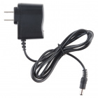
You could also use our 9 volt wall adapter if that suits your fancy and we have a number of Qwiic cable sizes to fit your needs.


Suggested Reading
If you aren’t familiar with the Qwiic system, we recommend reading here for an overview.
| Qwiic Connect System |
We would also recommend taking a look at the following tutorials if you aren’t familiar with them.
Serial Communication
Hardware Overview
Power
There are two separate power systems on the Quad Relay: a 5V system that powers the relays and a 3.3V system that powers the on board ATtiny84A and interfaces with a microcontroller through the four pin header or Qwiic connector.
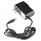
The on board barrel jack takes a power source in a range of 7-15V. It regulates the voltage and supplies power to the 5V power system of the relays. If your wall adapter or power source is at 5 volts like our 5V/2A Wall adapter then you can close the jumper on the underside of the product labeled 5V Wall Adapter (see Jumpers section below), and this will allow you to sidestep the on board regulator to power the 5V system directly. If you decide to go with a higher voltage wall adapter, be cognizant that the voltage regulator will start to heat up. With all the relay channels turned on the Quad Relay will pull ~250mA of current and at 9 Volts, that’s 2.25 Watts of power (mathematical!). Over time the regulator will get hot, but will remain functional. I suggest that if you expect to have all relay channels on for extended periods of time, that you go with a 5V power supply.

To provide 3.3V to the on board ATtiny84A you can use the plated through hole labeled 3V3 on the four pin header. Alternatively, you can plug a Qwiic connector into one of the two Qwiic connectors.

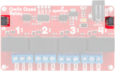
Relays
There are four single pole, double throw JZC-11F relays on the Qwiic Quad Relay. Each relay is capable of 5 Amps at 250VAC or 30VDC. These relays have an associated blue screw pin terminals that are aligned in order from left to right.

LEDs
There is a red power LED labeled PWR that indicates power from the barrel jack. There is also a blue stat LED for each relay labeled with their respective number 1-4.

Jumpers
There are two jumpers on the underside of the Qwiic Quad Relay. The first is the address jumper that changes the default I2C address from 0x6D to 0x6C. The second is the jumper labeled 5V Wall Adapter Jumper. If you intend to use a wall adapter or other power source that is below 7-15V than you can close this jumper to side step the on board voltage regulator, and provide 5V directly to the 5V power system.

Qwiic Connectors
The Qwiic connectors allow you to integrate easily into our Qwiic environment and allows you to prototype without the need for soldering! The 3.3V provided by the Qwiic connector will power the on board ATtiny84A. If you do not power the 3.3V power system this way, you can still provide power through the four pin header.
Safety Considerations
This product is designed to switch high power AC or DC and so has some inherent dangers. We’ve done our best to implement safety features directly into the design. To begin, the copper ground pour for the ATtiny84A circuitry is restricted to an area apart from the relays. In regards to the microcontroller, there are opto-isolators that isolate the 3.3V power system that it utilizes from the 5V power system of the relays. Next, the common pin of the relays have an air gap surrounding the pin on three sides to prevent any high voltage arcing. Finally, the traces on the relays are extra wide to handle the high amperage carrying potential of the relays.
Hardware Assembly
Introduction
Let’s walk through how to setup the relay to switch on a lamp or other device, but let’s begin with a short intro into relays. A relay is a switch. However unlike most switches, within the relay’s housing there is also a switching mechanism that is isolated from the switch. This is the relay’s defining feature because this separation between switching mechanism and switch, as well as the switching mechanism’s low power requirements, allows for low power micro-controllers to activate the switching mechanism without interfacing with whatever is getting “switched”. Shmow-zow!
We have three channels per relay broken out to blue screw pin terminals. The channels are labeled for their function. One is considered normally open or NO, the next channel is common or COM, and the final is normally closed or NC. The names explain the state of the channel with relation to the switch at rest. The normally closed channel is where the switch sits before the switching mechanism has been activated and conversely the normally open channel is where the switch would sit after. The common channel is, as the name implies, what the other two channels have in common. This is known as a single pole, double throw switch (SPDT). The image below helps to illustrate this characteristic of our particular relay.

When the switching mechanism is activated the thicker bar in the image above that connects normally closed to common flips over to connect normally open and common.
Assembly
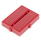
Onto the assembly. First I’m using a BlackBoard for it’s Qwiic capabilities and it’s powered via micro-USB. I have a button plugged into a breadboard, straddling the gap in the center, and jumper wires connecting it to pin 2 and GND on the blackboard.

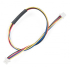
On the tail end is a Qwiic connector leading to the Quad Relay.
Let’s take a quick look at the lamp wire, before we look at the Quad Relay. Our goal here is to sever one of the two lamp wires, and plug the two ends of the cut wire into the relay which will reconnect the wire when we activate the switching mechanism. First, I’ve cut one of the two wires as shown to create a break in the connection.

I then peeled the wire apart and stripped the two ends.

We’ll put one end our wire in the COM channel, and the other we’ll have to decide upon. For this project we want our switch to act intuitively: when you activate the switching mechanism, the light switches on. There could be a case where you want the switching mechanism activated as its “rest” state. Since we’re going with a more normal approach we’ll cut our wire and place one end in common and the other in the normally open channel. Now when we activate the switching mechanism, the severed wire will be reconnected when the switch flips to the normally open channel connecting it and the common channel.
For the quad relay I’m powering the 5V system (the relays), with a 5V Wall Adapter, and the 5V Wall Adapter jumper closed underneath. The Qwiic cable from the black board is providing power to the 3.3V system as seen at the top of the picture below, and we have the lamp cable plugged into and the screw terminals tightened down on channels COM and NO.

Looking for information about safety and insulation? Check out the notes about Safety and Insulation from our Beefcake Relay Control Kit.
Now that our hardware is all set up, let’s take a look at the code that turns the lamp on.
Example Code
Let’s take a look at some example code fort the Qwiic Quad Relay. You can download all example codes from the GitHub repo by clicking the link below.
Qwiic Quad Relay Example Code (ZIP)
Example 1 - Relay Control
This is the code used for the lamp example above. Unzip and open up example one under Qwiic_Quad_Relay-master>Example Code>Example1_Relay_Control to follow along. At the top, let’s break down the defines that are provided. While all of them might not be necessary for your project and they weren’t for the lamp example, they are still displayed here to elucidate the functionality of the Quad Relay. First the default address 0x6D is included and it’s followed by the second I2C address 0x6C, which is commented out. If you’d rather use the latter then close the jumper on the underside of the product labeled ADDR.
language:c
#include <Wire.h>

#define RELAY_ADDR 0x6D // Default address - open jumper.
//#define RELAY_ADDR 0x6C // Address when jumper is closed.
The rest of the defines list all of the possible I2C commands possible. You can toggle each individual relay, toggle them all, turn them all on, or turn them all off. There is also a list of commands to check the state of each relay; whether the relay is on or off represented numerically by zero and 15 respectively.
language:c
// Here are the commands to turn on and off individual relays.
#define TOGGLE_RELAY_ONE 0x01
#define TOGGLE_RELAY_TWO 0x02
#define TOGGLE_RELAY_THREE 0x03
#define TOGGLE_RELAY_FOUR 0x04

// Here are the commands to turn them all off or on.
#define TURN_ALL_ON  0xB
#define TURN_ALL_OFF 0xA

//Here is the command to toggle every relay.
#define TOGGLE_ALL 0xC

// Here are the commands to check on the 'status' of the relay i.e. whether the
// relay is on or off.
#define RELAY_ONE_STATUS 0x05
#define RELAY_TWO_STATUS 0x06
#define RELAY_THREE_STATUS 0x07
#define RELAY_FOUR_STATUS 0x08

//Four buttons
const uint8_t yellow_btn = 2;
const uint8_t blue_btn = 3;
const uint8_t red_btn =  4;
const uint8_t green_btn =  5;
Let’s move on. In the following code, we define four buttons that when pressed, will send an I2C command to the associated relay. We have a small delay for debounce of 400 milliseconds associated with each button press. In the setup is a call to a function that gets the status of the relays: On or Off represented by zero and 15 respectively. This is detailed more extensively just after the next code block.
language:c
void setup()
{
  Wire.begin();
  Serial.begin(115200);

    //Use internal resitors to keep them in a known high state.
  pinMode(yellow_btn, INPUT_PULLUP);
  pinMode(blue_btn, INPUT_PULLUP);
  pinMode(red_btn, INPUT_PULLUP);
  pinMode(green_btn, INPUT_PULLUP);

  get_relays_status();
}

void loop()
{
    // Since we'll only ever want the relay to be on or off,
    // the logic is handled by the product. Here we're just pressing buttons and
  // putting a small 400 ms debounce.

    //button one, relay one!
  if(digitalRead(yellow_btn) == LOW){
    Serial.println("Yellow Button");
    Wire.beginTransmission(RELAY_ADDR);
    Wire.write(TOGGLE_RELAY_ONE);
    Wire.endTransmission();
        delay(400);
  }

    //button two, relay two!
  if(digitalRead(blue_btn) == LOW){
    Serial.println("Blue Button");
    Wire.beginTransmission(RELAY_ADDR);
    Wire.write(TOGGLE_RELAY_TWO);
    Wire.endTransmission();
        delay(400);
  }

    //button three, toggle every relay: on -> off and off -> on.
  if(digitalRead(red_btn) == LOW){
    Serial.println("Red Button");
    Wire.beginTransmission(RELAY_ADDR);
    Wire.write(TOGGLE_ALL);
    Wire.endTransmission();
        delay(400);
  }

    //button four, turn off all the relays!
  if(digitalRead(green_btn) == LOW){
    Serial.println("Green Button");
    Wire.beginTransmission(RELAY_ADDR);
    Wire.write(TURN_ALL_OFF);
    Wire.endTransmission();
        delay(400);
  }
}
The get_relays_status function is of particular interest. Getting the status of the relays works like an I2C buffer. Depending on the number of bytes requested, you will get the status of that many relays. For example, if you request the status of relay one and four bytes, then you’ll get the status of relay one plus the other three. If you request relay one and two bytes, then you’ll get the status of relay one and two. If you request the status of relay three and three bytes, then you’ll get the status of relay three, relay four, and relay one.
language:c
void get_relays_status(){
  int i = 1;
  Wire.beginTransmission(RELAY_ADDR);
  // Change the Wire.write statment below to the desired relay you want to check on.
  Wire.write(RELAY_ONE_STATUS);
  Wire.endTransmission();
  //  We want the states of all the relays so we're requesting four bytes, i.e.
  //  four relays. If you request 2 bytes, it will give you the state of two relays!
  Wire.requestFrom(RELAY_ADDR, 4);

  // Print it out, 0 == OFF and 15 == ON.
  while(Wire.available()){
    Serial.print("Relay ");
    Serial.print(i);
    Serial.print(": ");
    Serial.println(Wire.read());
    i++;
  }

}
Let There Be Light!
When we load up the code, and press the button we should see the relay one LED light up.

If your relay LED is on and the lamp doesn’t turn on, make sure you have the lamp turned on. We’ll let the relay handle turning it off and on from now on. Now if all is correctly assembled:

Algebraic!!
Resources and Going Further
Now that you’ve successfully got your SparkFun Qwiic Quad Relay up and running, it’s time to incorporate it into your own project!
For more information, check out the resources below:
Need some inspiration for your next project? Check out some of these other awesome related tutorials using relays. Be sure to check your current rating when handling the Qwiic Single Relay when browsing some of the other tutorials using relays.
Photon Remote Water Level Sensor
Blynk Board Project Guide
ESP8266 Powered Propane Poofer
Blynk Board Bridge Widget Demo
Beefcake Relay Control Hookup Guide
How to Build a Remote Kill Switch
Qwiic Single Relay Hookup Guide
learn.sparkfun.com | CC BY-SA 3.0 | SparkFun Electronics | Niwot, Colorado