SparkFun Qwiic Thermocouple Hookup Guide a learn.sparkfun.com tutorial
Available online at: http://sfe.io/t1110
Introduction
How many times have you asked yourself, "Self? How can I measure both the ambient temperature as well as that thing over there, AND set temperature limits to trigger interrupts so I don't have to constantly poll over I2C? And how can I make it as easy as possible?" Well, we've got your answer. SparkFun has 2 new thermocouple amplifier boards - the SparkFun Qwiic Thermocouple - PCC and the SparkFun Qwiic Thermocouple - Screw Terminals; both of which do all of the above with a resolution of 0.0625°C, and an accuracy of ±1.5°C (worst-case). The boards come ready to accept a K-type thermocouple, which gives a temperature range of -200°C to 1350°C. Additionally, the MCP9600 has four onboard temperature alerts for those interrupt triggers as well as the ability to enter alternate operation modes in order to save power.
Let's dig in and see how all this works!


Required Materials
To follow along with this tutorial, you will need the following materials. You may not need everything though depending on what you have. Add it to your cart, read through the guide, and adjust the cart as necessary.
Suggested Reading
If you aren’t familiar with the following concepts, we recommend checking out these tutorials before continuing. If you aren't familiar with the Qwiic system, we recommend reading here for an overview.
Clik here to view. |
| Qwiic Connect System |
Serial Terminal Basics
Processor Interrupts with Arduino
A Brief Theory of Operation
Thermocouples are fairly ubiquitous, being used in everything from industrial kilns and diesel engines to pilot light sensors and thermostats in your home or office. Let's take a brief moment to go over how they work.
Roughly a couple hundred years ago, a man named Thomas Seebeck discovered the principal that thermocouples use. He noticed that if you take two wires made of dissimilar metals, connect them at the two ends, and make a temperature gradient between one end and the other, a voltage potential formed and current flowed. One junction is held in the environment where the temperature of interest exists. This is known as the hot junction. The other junction is referred to as the cold junction.

There are many types of thermocouples, which mainly differ by the types of metals used in the two wires. The most common general purpose thermocouple is type K. They are made out of chromel and alumel. These two alloys produce a potential of approximately 41.276 µV/°C, and voltage out can be calculated using the equation below.
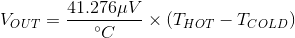
K-type thermocouples can read between from −200 °C to +1350 °C (−330 °F to +2460 °F) and are fairly stable.
Hardware Overview
MCP9600
At the heart of this board is the MicroChip Technology Inc MCP9600 Thermocouple EMF to Temperature Converter. Inside this chip are two temperature sensors, one for the thermocouple itself (the hot junction) and one for the chip itself (the cold junction). In addition, the MCP9600 has four onboard temperature alerts that allow you to set a temperature limit to trigger an interrupt when the temperature reaches a certain value. This frees up your microcontroller and your I2C bus. The MCP9600 can also be put into alternate operation modes in order to save power. The sensor supports a burst mode, where it will take a specifiable number of samples, return the results, and then go to sleep. More information can be found in the MCP9600 Datasheet (PDF).
| Image may be NSFW. Clik here to view.  | Image may be NSFW. Clik here to view.  |
|---|---|
| PCC Connector | Screw Terminal |
Power
Ideally, power will be supplied via the Qwiic connectors on either side of the board. Alternatively, power can be supplied through the header along the bottom side of the board labeled 3V3 and GND. The input voltage range should be between 2.7-5.5V.
| Image may be NSFW. Clik here to view.  | Image may be NSFW. Clik here to view.  |
|---|---|
| PCC Connector | Screw Terminal |
Qwiic Connectors
There are two Qwiic connectors on either end of the SparkFun Qwiic Thermocouple boards to provide power and I2C connectivity simultaneously. The I2C address of the board is 0x60 by default , but has 7 other address the board can be configured to use.
| Image may be NSFW. Clik here to view.  | Image may be NSFW. Clik here to view.  |
|---|---|
| PCC Connector | Screw Terminal |
I2C Pins
The I2C pins break out the functionality of the Qwiic connectors. Depending on your application, you can connect to these pins via the plated through holes for SDA and SCL.
| Image may be NSFW. Clik here to view.  | Image may be NSFW. Clik here to view.  |
|---|---|
| PCC Connector | Screw Terminal |
Jumpers
I2C Jumper
These boards are both equipped with pull-up resistors. If you are daisy-chaining multiple Qwiic devices, you will want to cut this jumper; if multiple sensors are connected to the bus with the pull-up resistors enabled, the parallel equivalent resistance will create too strong of a pull-up for the bus to operate correctly. As a general rule of thumb, disable all but one pair of pull-up resistors if multiple devices are connected to the bus. To disable the pull up resistors, use an X-acto knife to cut the joint between the two jumper pads highlighted below.
| Image may be NSFW. Clik here to view.  | Image may be NSFW. Clik here to view.  |
|---|---|
| PCC Connector | Screw Terminal |
ADDR Jumper
The MCP9600 uses an analog voltage to set the I2C address. By default, the ADDR jumper pulls the address pin low, which gives the board a default address of 0x60. Cutting the jumper pulls the address pin high through a 10K resistor, which will change the address to 0x67.
| Image may be NSFW. Clik here to view.  | Image may be NSFW. Clik here to view.  |
|---|---|
| PCC Connector | Screw Terminal |
For addresses other than 0x67, a resistor will need to be soldered. Refer to the table below for the resistor value and corresponding address.
| Address | Resistor (kΩ) |
|---|---|
| 0x60 | 0 |
| 0x61 | 2.2 |
| 0x62 | 4.3 |
| 0x63 | 7.5 |
| 0x64 | 13 |
| 0x65 | 22 |
| 0x66 | 43 |
| 0x67 | N/A |
Resistor location on each board:
| Image may be NSFW. Clik here to view.  | Image may be NSFW. Clik here to view.  |
|---|---|
| PCC Connector | Screw Terminal |
LED Jumper
Wanna turn off that pesky power LED? Cut this jumper.
| Image may be NSFW. Clik here to view.  | Image may be NSFW. Clik here to view.  |
|---|---|
| PCC Connector | Screw Terminal |
Board Dimensions
Feel free to click on either of the images below for a closer look!
| Image may be NSFW. Clik here to view.  | Image may be NSFW. Clik here to view.  |
| Qwiic Thermocouple Amplifier PCC | Qwiic Thermocouple Amplifier Screw Terminals |
Hardware Hookup
For this tutorial, we'll use the Amplifier board with the PCC connector. Grab your Qwiic cable and plug one end into the RedBoard Qwiic and the other end into the Thermocouple Amplifier.

Then you can connect the K-type Thermocouple into the PCC connector as so:

Plug in the RedBoard Qwiic When you are all set up, you should have something that looks like this:

Software Setup and Programming
If this is your first time using Arduino, please review our tutorial on installing the Arduino IDE. If you have not previously installed an Arduino library, please check out our installation guide.
SparkFun has written a library to work with the Qwiic Thermocouple. You can obtain this library through the Arduino Library Manager by searching for MCP9600. Find the one written by SparkFun Electronics and install the latest version. If you prefer downloading libraries manually, you can grab them from the GitHub Repository.
Example Code
Once you've installed the library, you should be able to find the examples in Arduino under File>Examples>SparkFun MCP9600 Thermocouple Library.

Example 1: Basic Readings
While all of the examples are well commented, let's quickly run through example 1 just to get your feet wet. The best part? It's pretty much plug and play. So go ahead and open up Example 1, or alternatively, copy and paste the code below into an Arduino window:
language:c
/*
  Temperature Measurements with the MCP9600 Thermocouple Amplifier
  By: Fischer Moseley
  SparkFun Electronics
  Date: July 8, 2019
  License: This code is public domain but you buy me a beer if you use this and we meet someday (Beerware License).

  This example outputs the ambient and thermocouple temperatures from the MCP9600 sensor.

  Hardware Connections:
  Attach the Qwiic Shield to your Arduino/Photon/ESP32 or other
  Plug the sensor onto the shield
  Serial.print it out at 115200 baud to serial monitor.
*/

#include <SparkFun_MCP9600.h>
MCP9600 tempSensor;

void setup(){
    Serial.begin(115200);
    Wire.begin();
    Wire.setClock(100000);
    tempSensor.begin();         // Uses the default address 0x60 for SparkFun
    //tempSensor.begin(0x66);   // Default address for SparkX

    //check if the sensor is connected
    if(tempSensor.isConnected()){
        Serial.println("Device will acknowledge!");
    }
    else {
        Serial.println("Device did not acknowledge! Freezing.");
        while(1); //hang forever
    }

    //check if the Device ID is correct
    if(tempSensor.checkDeviceID()){
        Serial.println("Device ID is correct!");
    }
    else {
        Serial.println("Device ID is not correct! Freezing.");
        while(1);
    }
}

void loop(){ //print the thermocouple, ambient and delta temperatures every 200ms if available
    if(tempSensor.available()){
        Serial.print("Thermocouple: ");
        Serial.print(tempSensor.getThermocoupleTemp());
        Serial.print("°C   Ambient: ");
        Serial.print(tempSensor.getAmbientTemp());
        Serial.print("°C   Temperature Delta: ");
        Serial.print(tempSensor.getTempDelta());
        Serial.print("°C");
        Serial.println();
    }
    delay(20); //don't hammer too hard on the I2C bus
}
What You Should See
Open up the Serial Monitor and make sure your baud rate is 115200. You should see something like the image below. If you move the hot junction (ie, the thermocouple wand) closer to a heat source, you should see the Thermocouple temperature go up.

Troubleshooting
If your product is not working as you expected or you need technical assistance or information, head on over to the SparkFun Technical Assistance page for some initial troubleshooting.
If you don't find what you need there, the SparkFun Forums are a great place to find and ask for help. If this is your first visit, you'll need to create a Forum Account to search product forums and post questions.
Resources and Going Further
Want more information on the Qwiic Thermocouple? Check out the links here:
Qwiic Thermocouple Amplifier PCC:
Qwiic Thermocouple Amplifier Screw Terminals:
Hardware and Library:
Need inspiration for more projects? We have loads of great Qwiic tutorials! Check 'em out!
RedBoard Edge Hookup Guide
TFMini - Micro LiDAR Module (Qwiic) Hookup Guide
Displaying Your Coordinates with a GPS Module
learn.sparkfun.com | CC BY-SA 3.0 | SparkFun Electronics | Niwot, Colorado