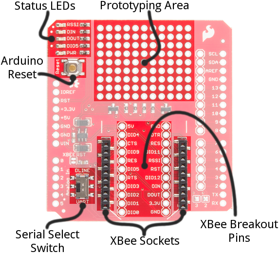
Quantcast
Channel: SparkFun Tutorials
Viewing all 1123 articles
Browse latest View live

LiPo USB Charger Hookup Guide

$
0
0

LiPo USB Charger Hookup Guide a learn.sparkfun.com tutorial

Available online at: http://sfe.io/t224

Introduction

We love LiPo batteries! They pack a walloping, power-supplying punch in a tiny, flat package. And, they’re incredibly easy to recharge, when that time comes. If you’re looking to make your project mobile and easily rechargeable, we can’t recommend this pairing enough: an 850 mAh LiPo battery and an embeddable USB LiPo charger.

battery and charger shot

This tutorial will explain how to use the USB LiPo Charger with any of our single-cell LiPo batteries. We’ll focus on the LiPo Charger and Battery Retail kit, but this information can be applied to that charger and any compatible battery.

Required Materials

Suggested Reading

  • Battery Technologies– Learn all about the different kinds of batteries used in portable projects, including the one most applicable to this tutorial: LiPos.
  • How to Power Your Project– LiPo’s are a great power source, but their not the right choice for every project. This tutorial will help you figure out which power source is best for you.
  • Voltage, Current, Resistance, and Ohm’s Law– There’ll be quite a bit of talk about current and resistance, so make sure you understand how they’re related with voltage.

Inputs and Outputs

On this page, we’ll dissect the USB charger, examining all of the inputs, outputs, and specifications of the board.

alt text

Charger Input – Power Supply

First, you’ll need something to supply power to the charger, so it can regulate power to the battery. Connect your power supply to one of these two inputs: a barrel jack (5mm outer diameter, 2.1mm center pole, center-positive) or a mini-B USB connector.

Your power supply voltage should be between 4.75 and 6V. A 5V USB supply – from a mini-B cable connected to either a computer USB port or wall adapter– makes for a perfect power source. Or, if you want to use the barrel jack input, we recommend the 5V wall adapter.

USB adapter5V wallwart

The current requirements of the supply will depend on how you’ve set the charge current on the board. By default, the charge current is set to 500mA, so make sure your supply can handle that. Computer and laptop USB ports are most suspect here; 500mA is the defined max a port can supply, and oftentimes they’re set to have an even lower output than that (e.g. 100mA).

You can safely attach both a 5V wall-wart and USB supply to the board. There is some protection (diodes!) on-board to prevent reverse current. The higher-voltage supply will source power to the chip.

Charger Output – Single-Cell LiPo Battery

Once you’ve connected a power supply to your charger, the next step is to connect a battery. This board will only charge a very specific battery, make sure it meets these requirements:

  • Single-Cell Batteries Only– Your LiPo should have a nominal voltage output of about 3.7V, and get up to around 4.2V at a full charge. That means single-cell LiPo’s only. If you have a multi-cell battery– something with a nominal voltage of 7.4V or more – this isn’t the charger for you.

Battery connected to charger

  • Battery Chemistry– The charger will only work with Lithium-Polymer or Lithium-Ion batteries.
  • Capacity Considerations– To avoid explosions (which are only very briefly fun), you shouldn’t charge these LiPos at a current over 1C. That means a 500mAh battery shouldn’t be given a charge current over 500mA, a 100mAh shouldn’t be charged higher than 100mA. This board is designed to charge at 500mA out-of-the-box, but it’s easy enough to change that rate. See the next page if your battery’s capacity is under 500mAh.

All of our compatible batteries are terminated with a white JST connector, which you can plug directly into the mating black connector next to the BATT IN→ label. If your battery is terminated with some, weird, non-JST connector, you can also use the un-populated 0.1"-pitch header directly behind the JST connector. Wires or other connectors can be soldered to this header, if desired.

System Output

The LiPo USB Charger is designed to be easily embeddable inside a project. The ←SYS OUT connector allows you to connect your battery output to the remaining parts of your project.

Using the system output

You can use the “SYS OUT” header to power a 3.3V Arduino Pro. All while leaving your battery connected to the charger.

As with the battery connection, you can use either the JST connector or the nearby 0.1"-pitch header to connect your project.

The SYS OUT output will connect your project directly to your battery. That means the battery supply voltage (somewhere between 3.6 and 4.2V) will power your project. Make sure you regulate that as necessary.

Charge Status LED

The on-board red Charging LED can be used to get an indication of the charge status of your battery.

Charge StateLED status
No BatteryFloating (should be OFF, but may flicker)
ShutdownFloating (should be OFF, but may flicker)
ChargingON
Charge CompleteOFF

If you want to add your own, larger LED, there’s an unpopulated footprint where you can solder either a 3mm or 5mm LED in the tiny (but bright!) red LED’s stead. Make sure you get the polarity right, though.

Setting the Charge Current

Before you plug a battery into the charger, you should be aware of your battery’s capacity and the charge current supplied by the charger. To be safe*, you should keep the charge current at or below 1C of your battery. That means you should charge your 850mAh battery at 850mA or less, and a 100mAh battery at 100mA or less.

The charge current controls how fast your battery will charge. If you have a 1000mAh battery, charging at 1000mA will fully charge that battery in 1 hour. Charging it at 500mA will mean a full charge takes twice as long – 2 hours. So more charge current is better…as long as it doesn’t exceed your battery’s specifications.

The featured component on the LiPo USB Charger board – an MCP73831– has a programmable charge current feature. It can be set to deliver anywhere between 15mA and 500mA to a battery. To program that value, a resistor is connected from the PROG pin to ground. There are already two resistors on-board, which can set the charge current to either 500mA and 100mA. A small jumper is used to select between those. You can also add your own resistor, to set a custom charge current.

Jumper-Selecting

Next to the charge-status LED there are three bare pads that form a two-way jumper. The center pad connects to the MCP73831’s PROG pin, and the outer two pads connect to a pair of resistors. The labels next to those outer pads indicate the charge current that they set.

Jumper location highlighted

If you look really closely at that jumper, you may see a small trace connecting the middle pad to the 500mA-labeled outer pad. As such, this board is configured to deliver a 500mA current by default.

To change the charge current to 100mA, you’ll need to cut that small trace between the pads (a hobby knife is recommended), and apply a solder blob to connect the 100mA-labeled pin to the center pad.

As an advanced trick, you can short both pads to the center (connecting both resistors in parallel) to set the charge current to 60mA.

Custom Charge Current

If neither 100mA or 500mA will work for you, there is an unpopulated resistor footprint to allow you to set a custom charge current.

Resistor plugged into board

Before adding the resistor, disconnect both jumpers discussed in the section above. Then use this equation to select your resistor:

\I_{charge} = \frac{1000V}{R_{prog}}\;\; \mathrm{(or)}\;\; R_{prog} = \frac{1000V}{I_{charge}}

For example, if you want to charge a 400mAh battery at exactly 400mA, solder in a 2.5kΩ resistor (you may have to series a 2.2k and 330).


* Most batteries include over-current protection– implemented on the little circuit board under the yellow tape – which will keep the battery from blowing up if you supply too much current. But it’s best to not rely on that circuit: you’ll save power and your sanity.

Resources & Going Further

Going Further

Now that you’ve got a replenishable source of power, how are you going to use it? Need some inspiration? Check out these tutorials:


learn.sparkfun.com |CC BY-SA 3.0 | SparkFun Electronics | Boulder, Colorado


Mini FET Shield Hookup Guide

$
0
0

Mini FET Shield Hookup Guide a learn.sparkfun.com tutorial

Available online at: http://sfe.io/t195

I Shall Call Him... Mini Me

The Mini FET Shield is an amazing little shield designed for the Arduino Pro Mini 3.3V 8MHz. If you’ve been using Arduino for some time, you may have noticed that one of the major limitations of the Arduino’s digital I/O is the amount of current it can provide on each pin, which is about 40mA. That’s enough current to light up a few LEDs or spin small DC motors, but to truly unleash your inner maker, you’re going to need more juice to drive those really big projects.

Mini FET Shield

Covered in this Tutorial

In this hookup guide, we’ll go over how the Mini FET Shield functions, discuss some of the different ways you can assemble the shield, and break down some Arduino code to get you started using higher current peripherals on your mobile Arduino projects.

Required Materials

In order to use the Mini FET Shield, you will need an Arduino Pro Mini 3.3V 8MHz. Please note that shield only works with the 3.3V version of the Pro Mini and NOT the 5V version.

There will be various other parts listed throughout the tutorial. Each use case for the Mini FET Shield is unique, so all of the parts in this tutorial are merely used to demonstrate the shield’s functionality and are by no means required.

Suggested Reading

Before you begin, make sure you are familiar with all these concepts and skills.

Board Overview

There’s a lot happening on this tiny board. Let’s break down each section and discuss in more detail how to use the Mini FET Shield.

Power

power hookup

The Mini FET shield was designed with battery power in mind. On the shield, you’ll notice the B+ and B-. Here, you can attach any battery between 1.8-5.5V, and the on-board regulator will regulate or boost it to 3.3V accordingly. This allows you to create mobile, battery powered projects that use AA, AAA, 9V, or LiPo batteries. It also provides a constant voltage to your devices, so motors and other peripherals will work at full force, even when the battery is nearing depletion.

The TPS61200 IC handles all the boosting/regulating. Keep in mind this IC is rated to deliver 600mA of output current. However, we’ve successfully put 2A through it. As always, be cautious about exceeding the maximum ratings for any device.

NOTE: This shield DOES NOT contain a battery charger. If you need to charge your battery, please see our charger offering.

The GND and 3.3V labeled on the right side indicate which pins are used to power the pro mini. Alternatively, if you chose to not use battery power for your project, you can power the shield through the Arduino Pro Mini. Note that because of this power scheme, this shield will only work with 3.3V Arduino Pro Mini and NOT the 5V Pro Mini.

Last, there is an 8-pin 3.3V rail (one for each MOSFET) and a 4-pin GND rail (one for the four remaining digital I/Os). These are conveniently placed next to the digital pins to allow buttons, motors, and other parts to be connected easily.

The MOSFETS

the FETs

These FDMA1024NZs are the stars of the show. Each of these ICs contain two N-channel MOSFETs, which is a type of transistor, and each is connected to pins 2-9, leaving us with 8 FETs to control. Transistors work just like electronically controlled switches. Thus, in order to turn on each transistor, we must pull the associated pin HIGH. This will allow the current to flow from the 3.3V source through your peripheral, through the transistor, and to ground, thus completing the circuit. This will become clearer as we connect more parts in the next section.

Digital I/O

digital I/O

Finally, there are four leftover digital I/Os: pins 10-13. These can be used as inputs or outputs and have a GND bus next to them to easily connect buttons and switches. If you do decide to add some inputs to these pins, remember to configure your pins as INPUT_PULLUP to turn on the internal pull-up resistors on the Pro Mini.

The remaining pins are labeled for your convenience. These pins don’t play a role in the function of the shield. However, you cam use a variety of headers, such as these stackable headers, to break out these pins, if you need. You can also solder wire directly to these pins.

Assembly

There is no one, correct way to assemble the Mini FET Shield. It can have a variety of headers added to it to customize it for your project. However, the method we show here could be considered the “standard” assembly method.

Although this is a mini shield, it acts just like a full-sized Arduino shield. Many of the same tips and techniques covered in our Arduino shield tutorial can be applied to this shield, particularly the Installing Headers section.

We recommend using female headers on the Pro Mini, and straight male headers on the Mini FET Shield. Alternatively, you could use machine pin female headers and machine pin male headers. They’re slightly more expensive, but they’ll give you a better looking final product as well as a thinner overall package.

Start by soldering the female headers to the Pro Mini. You can also add some right-angle male headers to the Pro Mini’s FTDI port.

female headers soldered to pro mini

Next, solder the male headers onto the shield. Make sure the side with the MOSFET ICs is the side facing up. You can use the female headers on the Pro Mini to hold the male headers in place while you solder, just like on a full-sized Arduino.

male headers solders to Mini FET Shield

The two should mate together like so…

shield on pro mini

Power

Now, we need to figure out a way to power our stack. The simplest way is to just solder a right-angle JST connector directly to the B+ and B- pins. The positive and negative pins on all our LiPo batteries should line up with B+ and B- as long you solder the JST connector in the correct orientation, with the opening facing pins 8 and 9. You will also need to clip the headers on pins 8 and 9 as flush as you can if you go this route. Otherwise, the battery may not fit correctly.

battery connector

Notice the pins cut flush with the PCB. Be careful when clipping these as getting too close may damage the pad.

Other options include using one of our many battery holders and soldering it directly to the B+ and B- pins. If you want power and charging built into one device, you could use the Power Cell. Or, if mobile power isn’t what you’re after, you could just attach this female barrel jack to JST adapter to the JST on B+ and B- and power it from the wall. You could also clip off the JST altogether, and solder the barrel jack directly to the board.

Peripherals

Now comes the fun part, adding all the things we want to move, spin, light up, and turn on. This is where your project may differ the most from this example. Just keep a few things in mind as you add your devices:

  • The Mini FET Shield can provide a lot more current than the Arduino alone, but, it too, has limitations. Each MOSFET within each IC is rated for 5A continuous drain current and 6A if it’s pulsed. Exceeding these ratings may damage the shield or the other boards attached to it. Still, 5A is a lot of current for such a tiny board!
  • The more devices you hook up, the more power draw you’re going to have and the quicker the battery will drain. Also keep the capacity of your battery in mind as you plan out your project.

In this example, I’m going to hook up a laser and one of our many varieties of 3-12V motors* to the shield, as well as a button and switch to control them. I used some good ol' stranded wire to connect everything to the shield.

peripherals hooked up

The connections in the picture above are as follows:

  • Motor (+) → 3.3V
  • Motor (−) → FET pin 2
  • Laser (+) → 3.3V
  • Laser (−) → FET pin 3
  • Switch → pin 10 & GND
  • Button → pin 11 & GND

*I later discovered that this particular motor does not draw a lot of current, about 10mA, which makes driving it with the Mini FET Shield a little on the overkill side. However, many DC motors will draw up to several hundred mA and will need to be driven by an external device.

Project Time

Now that we have all this hardware hooked up to the Mini FET Shield, what can we do with it? Well, for one, we can make a mobile light show!

Tools

To make a truly epic laser show, you’ll need a hot glue gun and a few stick of hot glue. Also, if you don’t already have some, you’ll need a hex key to assemble the Actobotics parts and a slightly smaller hex key for the set screws.

Hardware

Along with all the parts we used in the Assembly section, you’ll also need a LiPo battery, and some mounting hardware to hold everything in place. You can just use some angle brackets and some hot glue, or, if you want to get serious about your laser show, we’ve picked out some Actobotics parts to help you mount the motor and laser.


Going over building the mount is beyond the scope of this tutorial, but here’s a picture for guidance.

laser show with mini FET shield

Add a thin, bumpy layer of hot glue on the outer rim of the clear, acrylic wheel. When you shine the laser through the glue, it makes for an amazing visual effect reminiscent of an Aurora.

Firmware

Every project needs at least a little bit of code to get it going. Here is a simple sketch that turns the laser on with the switch and spins the motor when the button is pressed. Upload the code onto the Pro Mini using a 3.3V FTDI Basic.

language:c
int motor = 2;//write HIGH to turn on
int laser = 3;//write HIGH to turn on
int swtch = 10;
int button = 11;


void setup() {

pinMode(motor,OUTPUT);
pinMode(laser,OUTPUT);
pinMode(swtch, INPUT_PULLUP);//internal pullup
pinMode(button, INPUT_PULLUP);//internal pullup

digitalWrite(motor, LOW);
digitalWrite(laser, LOW);
}

void loop() {

  if(digitalRead(button) == LOW)//turn laser on with switch
   digitalWrite(motor, HIGH);
  else
    digitalWrite(motor, LOW);

  if(digitalRead(swtch) == LOW)//spin motor when button is pressed
   digitalWrite(laser, HIGH);
  else
    digitalWrite(laser, LOW);

}

There is one downside to driving a motor with the Mini FET Shield. Unlike a traditional H-bridge, such as the IC found on our Ardumoto Shield, the FET can only turn the motor in one direction. If you need your motor to move in both directions, you may need to find a different solution.

With that, you should have a working project that utilizes the features of the Mini FET Shield.

Resources and Going Further

Thanks for reading. As usual, if you have any feedback, please visit the comments or contact our technical support team at TechSupport@sparkfun.com. Please enjoy these other product resources and SparkFun tutorials for your reading pleasure.


learn.sparkfun.com |CC BY-SA 3.0 | SparkFun Electronics | Boulder, Colorado

Customizing LilyPad LED Colors

$
0
0

Customizing LilyPad LED Colors a learn.sparkfun.com tutorial

Available online at: http://sfe.io/t141

Feeling Limited?

Are you tired of the same old seven colors? We hear you.

plain ol' blue LEDs

Is your creativity outpacing current LED technology? Of course it is!

Are you ready to throw convention to the wind and invent your own LilyPad flavors? WE HOPE SO!

Sometimes a project demands a really specific shade of light, and if you want that special color, but don’t need the colors of the project to change or cycle, using RGB LEDs means paying extra money for features you don’t need! Here, I’ll show you how to easily and inexpensively open up your color options with standard LilyPad LEDs.

Suggested Reading

If you haven’t worked with wearable technology before, we suggest you visit these other tutorials first.

Materials

Photo of materials listed below

You’ll only need a few things to get started.

The first is Silicon Conformal Coating. Mine came from the local hardware store, but I threw an Amazon link up there in case you can’t find it!

Second is Sharpies. I’m using the 80’s Glam Collection, and I’ve never been happier.

Obviously, you’re going to want some LilyPad LEDs. I used white, because I wanted a really reliable match for my Sharpie colors, but if you want to try coloring over other base colors, have at it! Who am I to stand in the way of true love?

Coat Your LEDs

Let’s get started!

But first, let’s spend a moment with this very informative label. “Danger”, it says. “Poison Flammable”, it continues. The skull and crossbones figure is displayed prominently, though there are no indications that this product is intended for acts of piracy.

Please treat this product carefully, read all warning labels before starting, and don’t let kids participate in this part of the activity. If you must, try clear nail polish as an alternative. I prefer the silicon coating, because, when dried, it’s heat resistant. So, if I want to solder the LEDs later, I won’t have to worry them discoloring. The consistency is also just right for getting the coverage I want. But use whichever product is best and safest for your application!

LED and coating

The conformal coating has a built-in brush, which makes it easy to apply. You don’t want so much coating on the brush that it’s going to drip everywhere and make a mess, but you DO want it to flow easily from the brush to the LED.

Coating the LED

You should be leaving a nice blob of coating on top of the LED that covers both the LED and the surrounding area, but not the silver tabs on the sides. It might take a couple of tries to get this just right, but the surface tension of the coating is your friend here. Err on the side of caution, since you can always add more, but it’s going to be a lot harder to take some away.

Before and after LEDs

Here’s a properly coated LED next to an uncoated one, so you can see the difference. Let these dry completely before continuing to the next step.

Create Your Colors

The Fun Part!

It’s time to paint with all the colors of the wind!

Coloring LED with Sharpie

Color over the conformal coating with your markers. You want to tint a wide area, surrounding the LED completely, and not just covering the top of the LED. You can’t get too much coverage here, so really go to town. Try blending and layering colors, ombre effects, and different shades! Color fidelity is surprisingly high, so expect a very subtle effect with light colors, and strong results from your brightest colors.

finished LEDs

Here are a few of my favorites. You can see that pastels, like my mint green and baby blue, are understated. Here, they’re side-by-side with a white LED, so you can see the difference, but when they aren’t, the change is almost unnoticeable. Bolder colors, like teal, purple, hot pink, lime green, and orange, gave me very vibrant results!

I hope that, if you’ve had a project, costume, or design that’s just been waiting for the right LED color to come your way, this helps you to finally make it a reality! Share your results in the comments!

Resources and Going Further

For more E-textile, wearable fun, check out these other SparkFun tutorials:


learn.sparkfun.com |CC BY-SA 3.0 | SparkFun Electronics | Boulder, Colorado

MiniGen Hookup Guide

$
0
0

MiniGen Hookup Guide a learn.sparkfun.com tutorial

Available online at: http://sfe.io/t190

Introduction

alt text

The MiniGen was designed to be used either as a stand-alone board or as a shield that can be placed on top of an Arduino Pro Mini. It’s capable of generating sine, square, or triangle waves at up to 3MHz, and approximately 1Vp-p. The output is at a DC offset of Vcc/2. Neither the offset nor the amplitude can be varied.

By default, the MiniGen ships configured with a 3.3V regulator enabled, and thus, should only be used with 3.3V signals(or 3.3V Pro Minis, as linked above). There’s a jumper on the back that can be soldered over to bypass the regulator for 5V use; just be careful not to power the board with more than 5V if you bypass the regulator!

For more information about the MiniGen, please see the GitHub repository, where you’ll find a library, example code, and design files.

Suggested Reading

Before using the MiniGen, here are a few tutorials you should be familiar with:

Connections

Top

alt text

Here’s the top of the board. Due to the tight layout and lack of space on this shield, the labels had to live on the bottom side of the PCB.

There are two output sources: a 2x1 0.1" spaced header and a u.FL connector. The u.FL connector is shield as ground.

The output end of the board should be at the opposite end from the FTDI connector when installed on a Pro Mini.

Bottom

alt text

Take a look at the picture above. Let’s go through the labeled connections one at a time.

  • GND - Only one of these needs to be connected at a time; that means you can get away with headers on one side only.
  • VIN - By default, this goes to a 3.3V regulator. If you want to use the board with a 5V Pro Mini, you should put a blob of solder on the jumper pads on the back to connect all three together.
  • OUTPUT+ - This is the anti-aliased output from the AD9837. Expect to see a 1Vp-p signal, offset from ground by ½ Vin.
  • OUTPUT- - Connected to ground.
  • SCLK - SPI clock input. The SPI bus can handle up to 40MHz input.
  • SDATA - Input from the master device. Note that register contents cannot be read out from the AD9837 part; it lacks a DOUT pin.
  • FSYNC - Equivalent to chip select.

SPI interface

As mentioned above, the SPI interface can be driven at up to 40MHz. The SPI interface should be at or close to the supply voltage for the chip (3.3V by default).

If you elect to write your own SPI control for this, the clock idles low (CPOL = 0), and data is latched on the rising edge (CPHA = 1). This corresponds to SPI Mode 1.

Assembly

The MiniGen works as both a normal breakout board and as an add-on to the Arduino Pro Mini boards. Note that the SparkFun Pro Micro, Arduino Nano, and other similar form-factor boards won’t work, as they don’t have the necessary SPI pins in the same location.

Output connection

Before you go any further, think about what you’re going to do with the output of the MiniGen. Do you want bare wires (as I’ve done, here) on the output pads? Are you going to use the u.FL connector? .1" header pins? Make that decision now, and put your desired connector on the board.

alt text

I’ve elected to put two solid-core wires on this board, so I can plug the ends into a breadboard or clip a scope probe onto them. I left the lengths uneven to avoid having them touch and short.

Adding headers

We’ll start by explaining how to put male pin headers on the MiniGen. This will let us plug it into a breadboard easily, or into female headers soldered onto an Arduino Pro Mini (which we’ll go over later).

Start by trimming the pin headers to the right length. You’ll need 12 pins per side.

alt text

You can, of course, use any style of header you want: on display here are our female headers, our short male headers, and our long male headers. I’ll show you some options with each of these.

The easiest way to ensure that the pins are nicely perpendicular to your board (and thus, will mate easily with another board or breadboard) is to insert them into a breadboard. The width of the MiniGen is such that one row of pins inserted right next to the center line will place the other row of pins one column off the edge on the other side, as pictured below.

alt text

Once the pin headers are in place, you can lower the MiniGen board onto them. The board can be soldered on component side up or component side down; depending on what you plan to do with it, one of those is likely to be better.

If you put the board on the headers component side down, as shown below, you can see the pin labels. That makes this method better for use as a breakout board; however, you’ll be unable to put the board on the top side of a Pro Mini. We’ll talk about that in a minute.

alt text

Flipping the board over, component side up, will allow you to mount it on a Pro Mini board that has female headers on its top side. I’ll show you both of these cases fully assembled, so you can see the implications of each.

alt text

If you plan to put female headers on your Pro Mini, I strongly suggest that you solder down the male headers on the MiniGen, then use those to hold the female headers at an auspicious angle on the Pro Mini. That way, they’ll mate smoothly in the future.

alt text

You can see a couple of points: the pin headers on the MiniGen have been soldered in with the long pins on the opposite side from the components, and the receptacles are on the component side of the Pro Mini.

As I mentioned above, if you elected to put your headers in with the components “down”, you can’t put the MiniGen on top of your Pro Mini. However, if you use our long breakaway male headers, you can put the pins in from the bottom, and they’ll protrude on top enough for you to stack another board on top, such as the MiniFet Shield or a Pro Mini Protoshield. This has the disadvantage of covering up the u.FL connector on top of the board, but that may not be a problem for you.

alt text

If you use this method, be certain there’s a gap between the bottom of the Pro Mini and the components on the top of the MiniGen.

Arduino Library

The MiniGen has a fairly comprehensive Arduino Library to help users write Arduino code easily.

Accessing the Library

The library can be downloaded as part of the Github repository for the MiniGen board. Simply download the zip file of the entire repository, then copy the “libraries” directory from the “Arduino” folder in the unzipped repository into your Arduino Sketchbook directory. The location of your Sketchbook can be found in the “Preferences” window of the Arduino IDE. If you have trouble installing the library, please consult our tutorial.

Using the Library

To use the library, add the following two lines to the top of your sketch:

language:c
#include <MiniGen.h>
#include <SPI.h>

Note that both lines must be present; failure to include the SPI library will cause code compilation to fail.

Once you’ve included the library, you must instantiate a MiniGen object in your sketch, like this:

language:c
MiniGen sig_gen;

You can replace the name sig_gen with any name you like; our example sketches will use that name, however.

If you’re using the board with something other than an Arduino Pro Mini, you can change the chip select pin (referred to in the library and datasheet as the FSYNC pin) used by the code by calling the constructor like this, instead:

language:c
sig_gen = MiniGen(pin_number);

Change pin_number to the desired pin on the Arduino; note, however, that the SPI functionality of the Atmega requires that pin 10 be an output, so you’ll lose the ability to do other things with that pin.

Library Commands

Once you’ve created your MiniGen object, there are several commands that you can send to the MiniGen board to operate it.

language:c
sig_gen.reset();

This command will reset the MiniGen to its default behavior: it clears the phase offset registers, resets the frequency to 100Hz, and disables the output, resulting in a DC voltage at approximately ½ the supply voltage on the output.

language:c
sig_gen.setMode(newMode);

The newMode parameter can be one of the following values: MiniGen::TRIANGLE, MiniGen::SINE, MiniGen::SQUARE, or MiniGen::SQUARE_2. The frequency of the output will depend on the value in the selected frequency register; more on that below. For the first three options, the frequency will be at the set frequency; for the fourth, it will be one-half the set frequency.

language:c
sig_gen.selectFreqReg(reg);

The AD9837 chip has two registers that store possible output frequencies. These can be selected by passing the parameters MiniGen::FREQ0 and MiniGen::FREQ1 to this function. This allows the user to adjust the frequency by swapping registers rather than writing to the active register; since a full adjust of the frequency requires two SPI writes, this allows the change to take effect at once with no intermediate frequency step.

The FREQ registers are divided into a low word and a high word, each of which is 14-bits long; the output frequency is equal to the low word times 0.0596Hz plus the high word times 976.5Hz. The total output frequency is equal to the sum of the two registers.

language:c
uint32_t freqRegVal = sig_gen.freqCalc(desiredFrequency);

This helper function returns a 32-bit value (an unsigned long Arduino data type, or uint32_t in more general terms), which, when written to the AD9837 frequency register, will result in an output at desiredFrequency. The value passed to the function should be a floating point number, in Hz. When this 32-bit value is written to the FREQ registers, the result will be (approximately) desiredFrequency.

To write the value to the FREQ registers, there are several functions of interest. The reason for this is simple: speed. Writing the frequency value to the AD9837 can take anywhere from one to three SPI transactions; using the appropriate function allows the user to save execution time where possible.

language:c
sig_gen.adjustFreq(reg, mode, newFreq);

This method takes the longest. reg can be either MiniGen::FREQ0 or MiniGen::FREQ1, depending on where the user wants to write the value. mode can be either MiniGen::FULL, MiniGen::COARSE, or MiniGen::FINE. For the first, newFreq should be an 32-bit unsigned value (as returned by freqCalc(), or calculated by the user elsewhere); in that case, the frequency setting operation will require three SPI transactions. For the second and third, ‘newFreq’ should be a 16-bit unsigned value, and the operation will require two SPI transactions.

When the mode parameter is MiniGen::FULL, the value of the output will be equal to the passed parameter times 0.0596 Hz. When mode is MiniGen::COARSE, you will be writing to the high word of the register, and each count will increase the frequency by 976.5Hz. When mode is MiniGen::FINE, you’ll be writing to the low word, and each count will increase the frequency of the output by .0596Hz. Splitting the writes into coarse and fine allows the user to minimize the number of writes required to change the frequency.

language:c
sig_gen.FreqAdjustMode(newMode);
sig_gen.adjustFreq(reg, newFreq);

If speed is important, you can pre-select the mode. This reduces the write time to two SPI writes for FULL and one for COARSE or FINE. Note that this requires care on the part of the user to pass the appropriate value to adjustFreq(); if the mode is set to FULL and a 32-bit value isn’t passed, or to COARSE or FINE and a 16-bit value isn’t passed, the result will not be as desired.

language:c
sig_gen.selectPhaseReg(reg);
sig_gen.adjustPhaseShift(reg, newPhase);

It’s possible to adjust the phase shift between the input clock and the output signal. As is the case with setting the frequency, there are two phase shift registers. They can be selected by passing MiniGen::PHASE0 or MiniGen::PHASE1 as the reg parameter in the above functions.

For the newPhase parameter, the value should be a 16-bit unsigned value. Only 12 bits of that value are used, so it should be a maximum of 4095. Each count represents .00153 radians (.551 degrees). However, since the phase is measured relative to the input frequency, this setting is of limited value.

Resources and Going Further

Here are some useful resources to look at for the MiniGen board:

The MiniGen can be used for all kinds of signal synthesis, but one of the more intriguing possibilities it opens up is signal transmission by Frequency Shift Keying. By switching between the FREQ0 and FREQ1 registers, it’s possible to encode data on the output.

If you make anything neat using FSK with the MiniGen, or any other projects, let us know!

For more SparkFun tutorial fun, check out these other offerings:


learn.sparkfun.com |CC BY-SA 3.0 | SparkFun Electronics | Boulder, Colorado

BeagleBone Black Proto Cape Hookup Guide

$
0
0

BeagleBone Black Proto Cape Hookup Guide a learn.sparkfun.com tutorial

Available online at: http://sfe.io/t232

Board Overview

alt text

The BeagleBone Black Proto Cape is a great way to prototype or design custom capes for the BeagleBone Black. This cape gives you access to all gpio available on the BeagleBone Black. There are also two red LED’s available for user applications. The included EEPROM lets the user prototype cape description files, which are used by the BeagleBoard Foundation to register boards.

Suggested Reading

Before you start, we recommend the following background knowledge:

Assembly

First let’s solder some headers to the cape. There are two styles of headers you may choose from.

If you only plan on using one cape, straight headers will do just fine.

alt text

Header 2x23 (PRT-12791)

If you plan to use multiple capes, it is necessary to use stackable headers.

alt text

Stackable Header 2x23 (PRT-12790)

Soldering Headers

It is important when soldering the headers that they are held in straight. Tack two opposite pins and check the alignment before finishing the rest of the pins. When you are complete allow the cape to cool before inserting.

alt text

Removing capes can be quite difficult. Do not try to pull them off in one motion. Try to rock or slowly apply pressure to the corners. Separating in this fashion will prevent the pins from being bent.

alt text

Let’s take a look at how the prototyping area is laid out.

Proto Area

There is plenty of space on which to prototype. There are two power buses provided along with ground connections on both sides of the board, all .1" spaced through holes.

alt text

Two LED’s have been provided for quick and easy debugging or general purpose use.

alt text

Simply apply a current to each LED to illuminate. They work with both 3.3v and 5v inputs.

Now, let’s look at the EEPROM and its features.

Using the EEPROM

The Cape EEPROM is great for storing pin configuration data. The cape EEPROM is read by the BeagleBone Black during boot. It can then automatically setup the pins for use. There are several steps to understand how the EEPROM is used. For now, we will show you the possible settings available. The cape comes with a blank EEPROM.

alt text

The default address for the EEPROM is 0x57. You can change it to addresses 0x54 - 0x57 with the selection of the two address jumpers. They are Labled A0 and A1. Changing the address of the Cape is important when you are using multiple capes.

Address Table

A2 A1 A0 7-bit address
100
0x54
101
0x55
110
0x56
111
0x57

Once you have created your next great thing you can register your settings with the BeagleBone foundation. This registration allows them to upload your settings to the latest operating system available. This removes the need for users to setup their board to use your cape.

Resources and Going Further

Now, go forth and build something awesome! Here are some additional links to get you started using the BeagleBone Black.

Further reading:

If you have any problems or questions, our technical support department can help. Please don’t hesitate to contact us. We also love to hear about your projects!


learn.sparkfun.com |CC BY-SA 3.0 | SparkFun Electronics | Boulder, Colorado

Are You Okay? Widget

$
0
0

Are You Okay? Widget a learn.sparkfun.com tutorial

Available online at: http://sfe.io/t229

Introduction

When Elizabeth and I got to talking about friends, neighbors, parents, and children we worry about, there was a theme: if we knew they were OK, it would be enough. The hard part is in not knowing if they came home last night or got up this morning. Elizabeth and I worked out what we wanted it to do on my embedded software podcast. We have the technology to alleviate such worries, such as the Are-You-OK? Widget. The Are-You-OK widget contains an Electric Imp, an accelerometer, and an RGB LED to connect to wireless networks to notify loved ones if you’re ok or not.

Finished Project

If you put it in a stuffed animal, the person you care about can pat it every day. If they fail to do so, the Imp will tweet at you, send you email, and/or text your phone. Of course, you could put it on their refrigerator, so you’d know they were OK and eating.

This is definitely an advanced tutorial. I’ll show you how I put together the hardware and the software, but, if you haven’t tried Electric Imp before, this may not be the place to start.

Required Materials

The items you will need for this are:

I chose right angle connectors in the kit because it goes better into a box or stuffed animal. Your form factor may vary. I also really like jumper wires over soldering but, if you are more confident on the hardware side, I won’t stop you from soldering. If you are building a plush, you may want to locate the LED and accelerometer away from the main board and batteries.

You will also need this tools and supplies:

Suggested Reading

Building The Hardware

Here’s an overview of the hardware hookup:

Schematic overview

The build is fairly straight forward. We start with soldering:

  1. Attach a two pin header to the Electric Imp breakout board for GND and VIN. Solder on the battery wires. Hot glue them to reinforce the connection.
  2. Break off 9 pins from the header, and solder those to the Imp breakout board.
  3. Since you’ll need two ground wires (one for the accelerometer and one for the LED), cut the end off of one jumper wire, strip the coating, and solder it to the Imp breakout board. (We can wait to hot glue until the jumper wires are in place.)
  4. Solder a 6-pin header onto the accelerometer.

Now wire up the system:

Imp Breakout PinWire ColorGoes ToUse
PIN1BlueAccel's I1Interrupt to wake up the Imp.
PIN2RedLED's red legPWM red
PIN5BlueLED's blue legPWM blue
PIN7GreenLED's green legPWM green
PIN8YellowAccel's SCLI2C clock signal
PIN9GreenAccel's SDAI2C data signal
3V3RedAccel's 3.3VPower
GNDBlackAccel's GNDGround
GNDBlackLED cathode (longest leg)Ground

After you are done, the result should look something like this:

Are You OK wiring photo

Note: the extra ground wire is soldered on the 2-pin power header and is ready for a battery connection to be soldered to it.

Loading the Code

As with any good Imp program, there are two halves to this code: the device (the Imp itself) and the agent (a server-side process that handles Internet requests and responses). Create a new model in the Imp IDE, and copy/paste the code below into the proper half of the IDE.

Imp IDE Example

Then check out the next couple of pages, where we dissect each section of the code. You’ll need to change some constants to make the code work for you.

Note: You can grab the most up-to-date agent and device codes here on GitHub.

Device Code

language:JavaScript
// Are you ok? widget for monitoring loved ones

// It is ok to use, reuse, and modify this code for personal or commercial projects.
// License: Beerware.
// If you do, consider adding a note in the comments giving a reference to
// this project and/or buying me a beer some day.

/**************************** User parameters ***************************************/
// Imp's hardware.voltage reads the output of the regulator so we don't see the
// whole range of the batteries, do the best with the info available
const MAX_EXPECTED_VOLTAGE = 3.3; // max readable
const MIN_EXPECTED_VOLTAGE = 2.6; // dying
const MIN_GOOD_STATE_OF_CHARGE = 25; // percent


// when there is movement, how much movement does there have to be
// to get the accelerometer to wake up the device
const ACCEL_TAP_THRESHOLD = 10; // experimentally derived threshold
const ACCEL_TRANSIENT_THRESHOLD = 0x02;  // experimentally derived threshold

// the LED ramps up to a color, holds for a bit, then ramps down
const LED_HOLD_TIME = 5.0; // seconds
const LED_RAMP_STEP_TIME = 0.05; // seconds per ramp step (0.05 = 200Mhz)
const LED_RAMP_STEPS = 20; // steps in ramp at timing above


/**************************** Hardware *******************************************/
 /* Pin Assignments according to silkscreen
 * Pin 1 = Input: wakeup interrupt from accelerometer
 * Pin 2 = PWM Red
 * Pin 5 = PWM Blue
 * Pin 7 = PWM Green
 * Pin 8 = I2C SCL  (yellow wire for me)
 * Pin 9 = I2C SDA  (green wire for me)
*/

wakeupPin <- hardware.pin1;
redHWPin <- hardware.pin2;
greenHWPin <- hardware.pin5;
blueHWPin <- hardware.pin7;
i2c <- hardware.i2c89;
i2c.configure(CLOCK_SPEED_400_KHZ);
/**************************** LED *******************************************/
// Variable to represent LED state
class LEDColor
{
    redPin = null
    greenPin = null
    bluePin = null

    goalLED = [0xFF, 0xFF, 0xFF]; // power on goal is white
    currentLED = [0, 0, 0];
    inLEDRamp = false; // prevents multiple LED flares

    constructor(redPin, greenPin, bluePin) {
        // PWM frequency in Hz
        local pwm_f = 500.0;
        redPin.configure(PWM_OUT, 1.0/pwm_f, 0.0);
        greenPin.configure(PWM_OUT, 1.0/pwm_f, 0.0);
        bluePin.configure(PWM_OUT, 1.0/pwm_f, 0.0);

        this.redPin = redPin
        this.greenPin = greenPin
        this.bluePin = bluePin
        this.off();
    }

    function update() {
        local div =  (1.0/255.0);
        this.redPin.write( currentLED[0] * div);
        this.greenPin.write( currentLED[1] * div);
        this.bluePin.write( currentLED[2] * div);
    }
    function off() {
        this.redPin.write(0);
        this.greenPin.write(0);
        this.bluePin.write(0);
    }

    function setGoalColor (red, green, blue)
    {
        if (inLEDRamp) {
            // not updating if we are already doing something
        } else {
            goalLED[0] = red;
            goalLED[1] = green;
            goalLED[2] = blue;

            ledRamp();
            inLEDRamp = true;
        }
    }
}
local rgbLed = LEDColor(redHWPin, greenHWPin, blueHWPin);

// this function looks at the difference between the goal LED
// and the actual LED and finds a way to smoothly transition
function ledRamp()
{
    local difference = [0, 0, 0];
    local totalDifference = 0;
    local i;
    for (i = 0; i < 3; i++) {
        difference[i] = rgbLed.goalLED[i] - rgbLed.currentLED[i];
        if (0 < difference[i] && difference[i] < LED_RAMP_STEPS) {
            difference[i] = LED_RAMP_STEPS; // will be 1 after divide

        } else if (0 > difference[i] && -difference[i] < LED_RAMP_STEPS) {
            difference[i] = -LED_RAMP_STEPS; // will be -1
        }
        rgbLed.currentLED[i] += (difference[i] / LED_RAMP_STEPS);
        totalDifference += difference[i];
    }
    if (-3 < totalDifference && totalDifference < 3) {
        local goal = 0;
        for (i = 0; i < 3; i++) {
            goal += rgbLed.goalLED[i];
            rgbLed.currentLED[i] = rgbLed.goalLED[i];
            rgbLed.goalLED[i] = 0;
        }
        if (goal == 0) {
            // finished
            rgbLed.inLEDRamp = false;
            rgbLed.off();
            GetReadyToSleep();

        } else {
            rgbLed.update();
            imp.wakeup(LED_HOLD_TIME, ledRamp);  // it will start ramping down
        }
    } else {
        rgbLed.update();
        imp.wakeup(LED_RAMP_STEP_TIME, ledRamp);
    }
}

/************************ Battery monitoring ***************************************/
// This project originally used a rechargeable battery with a MAX17043 LiPo fuel
// gauge to determine the state of charge (SOC). However, since the Impee is sleeping
// so much, we might get a reasonable battery life out of 4AAs. To get back to
// rechargeable, replace this code with that found in rechargeable_device.

function FuelGaugeResetFromBoot()
{
    // do nothing
}

function FuelGaugeReadSoC()
{
    local voltage = hardware.voltage();
    local normalizedVoltgage = (voltage - MIN_EXPECTED_VOLTAGE) / (MAX_EXPECTED_VOLTAGE - MIN_EXPECTED_VOLTAGE);
    if (normalizedVoltgage < 0) normalizedVoltgage = 0
    local percent = math.floor(100 * normalizedVoltgage);

    return percent;
}

/************************ Accelerometer ***************************************/
// Many thanks to https://gist.github.com/duppypro/7225636
// I mooched much of that code for the MMA8452Q accelerometer, though I made some
// changes for efficiency

const ACCEL_ADDR = 0x3A // 0x1D << 1
// Note: if your accelerometer has the SAO line pulled down
// (the resistor on the Sparkfun board), change the address to
/// const ACCEL_ADDR = 0x38 // 0x1C << 1

// MMA8452 register addresses and bitmasks
const STATUS        = 0x00
const OUT_X_MSB        = 0x01
const WHO_AM_I         = 0x0D
const I_AM_MMA8452Q    = 0x2A // read addr WHO_AM_I, expect I_AM_MMA8452Q
const INT_SOURCE       = 0x0C
    const SRC_ASLP_BIT        = 0x80
    const SRC_TRANSIENT_BIT   = 0x20
    const SRC_ORIENTATION_BIT = 0x10
    const SRC_PULSE_BIT       = 0x08
    const SRC_FF_MT_BIT       = 0x04
    const SRC_DRDY_BIT        = 0x01

const TRANSIENT_CFG = 0x1D
const TRANSIENT_SRC = 0x1E
const TRANSIENT_THRESHOLD = 0x1F
const TRANSIENT_COUNT = 0x20

const PULSE_CFG = 0x21
const PULSE_SRC = 0x22
const PULSE_THSX = 0x23
const PULSE_THSY = 0x24
const PULSE_THSZ = 0x25
const PULSE_TMLT = 0x26
const PULSE_LTCY = 0x27
const PULSE_WIND = 0x28


const CTRL_REG1         = 0x2A
    const GOAL_DATA_RATE = 0x20 // 100 Hz
    const CLEAR_DATA_RATE =0xC7
    const LNOISE_BIT       = 0x4
    const F_READ_BIT       = 0x2
    const ACTIVE_BIT       = 0x1

const CTRL_REG2        = 0x2B
    const ST_BIT           = 0x7
    const RST_BIT          = 0x6
    const SLEEP_OVERSAMPLE_CLEAR = 0xE7
    const SLEEP_OVERSAMPLE_SET = 0x18 // 11 = low power
    const AUTOSLEEP_BIT         = 0x4
    const NORMAL_OVERSAMPLE_CLEAR = 0xFC
    const NORMAL_OVERSAMPLE_SET = 0x03 // 11 = low power

const CTRL_REG3        = 0x2C
    const WAKE_TRANSIENT_BIT     = 0x40
    const WAKE_ORIENTATION_BIT   = 0x20
    const WAKE_PULSE_BIT         = 0x10
    const WAKE_FREEFALL_BIT      = 0x08
    const IPOL_BIT               = 0x02

const CTRL_REG4        = 0x2D
    const INT_EN_ASLP_BIT        = 0x80
    const INT_EN_TRANSIENT_BIT   = 0x20
    const INT_EN_ORIENTATION_BIT = 0x10
    const INT_EN_PULSE_BIT       = 0x08
    const INT_EN_FREEFALL_MT_BIT = 0x04
    const INT_EN_DRDY_BIT        = 0x01

const CTRL_REG5        = 0x2E


// Writes a single byte (dataToWrite) into addressToWrite.  Returns error code from i2c.write
// Continue retry until success.  Caller does not need to check error code
function writeReg(addressToWrite, dataToWrite) {
    local err = null
    while (err == null) {
        err = i2c.write(ACCEL_ADDR, format("%c%c", addressToWrite, dataToWrite))
        // server.log(format("i2c.write addr=0x%02x data=0x%02x", addressToWrite, dataToWrite))
        if (err == null) {
            server.error("i2c.write of value " + format("0x%02x", dataToWrite) + " to " + format("0x%02x", addressToWrite) + " failed.")
        }
    }
    return err

}

// Read numBytes sequentially, starting at addressToRead
// Continue retry until success.  Caller does not need to check error code
function readSequentialRegs(addressToRead, numBytes) {
    local data = null

    while (data == null) {
        data = i2c.read(ACCEL_ADDR, format("%c", addressToRead), numBytes)
        if (data == null) {
            server.error("i2c.read from " + format("0x%02x", addressToRead) + " of " + numBytes + " byte" + ((numBytes > 1) ? "s" : "") + " failed.")
        }
    }
    return data
}

function readReg(addressToRead) {
    return readSequentialRegs(addressToRead, 1)[0]
}
function AccelerometerSetActive(mode) {
    // Sets the MMA8452Q active mode.
    // 0 == STANDBY for changing registers
    // 1 == ACTIVE for outputting data
    if (mode) {
        writeReg(CTRL_REG1, readReg(CTRL_REG1) | ACTIVE_BIT)
    } else {
        writeReg(CTRL_REG1, readReg(CTRL_REG1) & ~ACTIVE_BIT)
    }
}
// Reset the accelerometer
function AccelerometerResetFromBoot() {
    local reg = null;

    server.log("Looking for accelerometer...")
    do {
        reg = readReg(WHO_AM_I)  // Read WHO_AM_I register
        if (reg == I_AM_MMA8452Q) {
            server.log("Found MMA8452Q.  Sending RST command...")
            break
        } else {
            server.error("Could not connect to MMA8452Q: WHO_AM_I reg == " + format("0x%02x", reg))
            imp.sleep(i2cRetryPeriod)
        }
    } while (true)

    // send reset command
    writeReg(CTRL_REG2, readReg(CTRL_REG2) | RST_BIT)

    do {
        reg = readReg(WHO_AM_I)  // Read WHO_AM_I register
        if (reg == I_AM_MMA8452Q) {
            server.log("Accelerometer found.")
            break
        } else {
            server.error("Could not connect to MMA8452Q: WHO_AM_I reg == " + format("0x%02x", reg))
            imp.sleep(i2cRetryPeriod)
        }
    } while (true)

    AccelerometerSetActive(false);
    writeReg(CTRL_REG1, 0x1A); // 100 Hz ODR + fast read + low noise

    // Set up accel for transient detection, see
    // http://cache.freescale.com/files/sensors/doc/app_note/AN4071.pdf
    writeReg(TRANSIENT_CFG, 0x1E); // Enable X Y Z Axes and enable the latch
    writeReg(TRANSIENT_THRESHOLD, ACCEL_TRANSIENT_THRESHOLD);
    writeReg(TRANSIENT_COUNT, 0x05); // 50ms
    reg = readReg(TRANSIENT_SRC) // this clears the register

    // Set up accel for single tap pulse detection, see
    // http://cache.freescale.com/files/sensors/doc/app_note/AN4072.pdf
    writeReg(PULSE_CFG, 0x55); // Enable X Y Z Axes and enable the latch
    writeReg(PULSE_THSX, ACCEL_TAP_THRESHOLD);
    writeReg(PULSE_THSY, ACCEL_TAP_THRESHOLD);
    writeReg(PULSE_THSZ, ACCEL_TAP_THRESHOLD);
    writeReg(PULSE_TMLT, 0x03); // 30ms at 100Hz ODR
    writeReg(PULSE_LTCY, 100);  // 100ms at 100Hz ODR
    reg = readReg(PULSE_SRC) // this clears the register

    writeReg(CTRL_REG4, INT_EN_TRANSIENT_BIT | INT_EN_PULSE_BIT);
    writeReg(CTRL_REG5, INT_EN_TRANSIENT_BIT | INT_EN_PULSE_BIT);

    writeReg(CTRL_REG3, WAKE_TRANSIENT_BIT | WAKE_PULSE_BIT | IPOL_BIT);  // move to int1

    AccelerometerSetActive(true);
}
function readAccelData() {
    local rawData = null // x/y/z accel register data stored here, 3 bytes
    rawData = readSequentialRegs(OUT_X_MSB, 3)  // Read the three raw data registers into data array
    return rawData;
}

function AccelerometerIRQ() {
    local reg = null


    if (wakeupPin.read() == 1) { // only react to low to high edge
        IndicateGoodInteraction();
        reg = readReg(INT_SOURCE)
        if (reg & SRC_TRANSIENT_BIT) {
            reg = readReg(TRANSIENT_SRC) // this clears SRC_TRANSIENT_BIT
            server.log(format("Transient src 0x%02x", reg))
            agent.send("motionDetected", "soft gentle motion.");
        }


        if (reg & SRC_PULSE_BIT) {
            reg = readReg(PULSE_SRC) // this clears SRC_PULSE_BIT
            server.log(format("Pulse src 0x%02x", reg))
            agent.send("motionDetected", "hard rapping.");
        }

    } else {
//        server.log("INT LOW")
    }
} // end AccelerometerIRQ

/************************ Device code  ***************************************/
function GetReadyToSleep()
{
    local sleepSeconds = 3600; // an hour
    // this will effectively reset the system when it comes back on
    server.sleepfor(sleepSeconds);
}

function CheckBatteryAndGoToSleep()
{
    agent.send("batteryUpdate", FuelGaugeReadSoC());
    server.log("going  to sleep");
    imp.onidle(GetReadyToSleep);
}

function IndicateGoodInteraction()
{
    rgbLed.setGoalColor(255, 255, 255); // white
}
function IndicateLowBattery()
{
    rgbLed.setGoalColor(200, 200, 0); // yellow
}
function IndicateNoWiFi()
{
    rgbLed.setGoalColor(255, 0, 0); // red
}

function HandleReasonForWakeup(unused = null)
{
    local reason = hardware.wakereason();
    local stateOfCharge = FuelGaugeReadSoC();
    local timeout = 30;


    if (reason == WAKEREASON_TIMER) {
        // quiet wakeup
        server.log("Timer wakeup")
        CheckBatteryAndGoToSleep();
    } else {
        if  (!server.isconnected()) {
            IndicateNoWiFi()
        }
        if (stateOfCharge < MIN_GOOD_STATE_OF_CHARGE)
        {
            server.log("Low battery " + stateOfCharge)
            IndicateLowBattery();
        }

        if (reason == WAKEREASON_PIN1) {
            server.log("PIN1 wakeup")
            AccelerometerIRQ();
        } else { // any other reason is a reset of sorts
            server.log("Reboot")
            AccelerometerResetFromBoot();
            FuelGaugeResetFromBoot();
        }
    }
}

// things to do on every time based wake up
imp.setpowersave(true);

// on error: don't try to reconnect, throw an error so we can indicate a
// problem to the user
server.setsendtimeoutpolicy(RETURN_ON_ERROR, WAIT_TIL_SENT, 30);

// Configure interrupt for wakeup.  Connect MMA8452Q INT1 pin to imp pin1.
wakeupPin.configure(DIGITAL_IN_WAKEUP, AccelerometerIRQ);

// figure out why we woke up
if  (!server.isconnected()) {
    // we probably can't get to the internet, try for
    // a little while (3 seconds), then get pushed to
    // HandleReasonForWakeup where IndicateNoWiFi will be called
    server.connect(HandleReasonForWakeup, 3)
} else {
    HandleReasonForWakeup();
}

Agent Code

language:JavaScript
// Are you ok? widget for monitoring loved ones

// license: Beerware.
// It is ok to use, reuse, and modify this code for personal or commercial projects.
// If you do, consider adding a note in the comments giving a reference to
// this project and/or buying me a beer some day.

// This agent monitors the device, making sure it communicates
// and gets moved by its user regularly. This will also send messages
// via twitter (email and Twilio texting is an exercise
// left to the next person).

/************************ Settings  ***************************************/

// debug output frequency: these prevent twitter flurries where you
// get the same message 10 times because you are tapping the device
const dtDebugMessageMotionDetected = 80; // seconds
const dtDebugMessageBatteryUpdateDetected = 600; // seconds

// This is how long the device will go without an update from the
// user before it cries for help
//      43200   ==> 12 hours ==> three times a day
//      129600  ==> 36 hours ==> every day (not same time every day)
//      216000  ==> 60 hours ==> every couple days
const dtNoMotionDetected = 129600; // seconds
const dtNoBatteryUpdate = 21600; // seconds (21600 ==> 6 hours)
const dtEverythingFineUpdate = 432000; // seconds (432000 ==> 5 days)

const MIN_GOOD_STATE_OF_CHARGE = 25; // percent

// Twitter permissions for @ayok_status
// It is ok to use this as long as you update the monitoredDevices
// so it prints your mane.
// Also note, it is for debug: if abused, the permissions will
// change (and remember others can see these tweets!).
_CONSUMER_KEY <- "HxwLkDWJTHDZo5z3nENPA"
_CONSUMER_SECRET <- "HvlmFx9dkp7j4odOIdfyD9Oc7C5RyJpI7HhEzHed4G8"
_ACCESS_TOKEN <- "2416179944-INBz613eTjbzJN4q4iymufCcEsP5XJ6xW5Lr8Kp"
_ACCESS_SECRET <- "1YdwAiJViQY45oP8tljdX0PGPyeL8G3tQHKtO43neBYqH"

// Twilio set up for texting
// http://forums.electricimp.com/discussion/comment/4736
// more extensive code https://github.com/joel-wehr/electric_imp_security_system/blob/master/agent.nut

// Mailgun for emailing
// http://captain-slow.dk/2014/01/07/using-mailgun-with-electric-imp/

/************************ Handle setting the device's name ***************************************/
// You have to set up your unit the first time by putting in a URL:
// https://agent.electricimp.com/{agentUrl}/settings?name={nameValue}&attn={attnValue}
// Look at the top of the Imp editor for you agent URL, you'll see something like
//    https://agent.electricimp.com/abce1235  <-- random string numbers and letters
// So you'll build up one that looks like
// https://agent.electricimp.com/abce1235/settings?name={Maxwell}&attn={@logicalelegance}
// Where Maxwell is the name of the unit and @logicalelegance is where I want messages to be sent.

// default settings
settings <- {
    name = "Unknown",   // name of the unit
    attn = ""           // who to send messages to
};

// Loads settings, if they exist
function loadSettings() {
    // load data
    local data = server.load();

    // if there are settings
    if ("settings" in data) {
        settings.name = data.settings.name;
        settings.attn = data.settings.attn;
    }
}

// Load settings on agent start/restart
loadSettings();

// Saves the settings with server.save
function saveSettings(newName, newAttn) {
    // load settings
    local data = server.load();

    // if settings isn't in the stored data
    if (!("settings" in data)) {
        // create settings table in data
        data["settings"] <- { name = "", attn = "" };
    }

    // set new values
    settings.name = newName;
    settings.attn = newAttn;

    // save values
    data.settings.name = newName;
    data.settings.attn = newAttn;
    server.save(data);
}


function httpHandler(req, resp) {
    // grab the path the request was made to
    local path = req.path.tolower();
    // if they made a request to /settings:
    if (path == "/settings" || path == "/settings/") {
        // grab query parameters we need
        if ("name" in req.query && "attn" in req.query) {
            // save them
            saveSettings(req.query.name, req.query.attn);
            // respond with the new settings
            resp.send(200, http.jsonencode(settings));
            return;
        }
    }
    // if they didn't send settings pass back a 200, OK
    resp.send(200, "OK");
}

// attach httpHandler to onrequest event
http.onrequest(httpHandler);


/************************ Twitter ***************************************/
// from: github.com/electricimp/reference/tree/master/webservices/twitter
helper <- {
    function encode(str) {
        return http.urlencode({ s = str }).slice(2);
    }
}

class TwitterClient {
    consumerKey = null;
    consumerSecret = null;
    accessToken = null;
    accessSecret = null;

    baseUrl = "https://api.twitter.com/";

    constructor (_consumerKey, _consumerSecret, _accessToken, _accessSecret) {
        this.consumerKey = _consumerKey;
        this.consumerSecret = _consumerSecret;
        this.accessToken = _accessToken;
        this.accessSecret = _accessSecret;
    }

    function post_oauth1(postUrl, headers, post) {
        local time = time();
        local nonce = time;

        local parm_string = http.urlencode({ oauth_consumer_key = consumerKey });
        parm_string += "&" + http.urlencode({ oauth_nonce = nonce });
        parm_string += "&" + http.urlencode({ oauth_signature_method = "HMAC-SHA1" });
        parm_string += "&" + http.urlencode({ oauth_timestamp = time });
        parm_string += "&" + http.urlencode({ oauth_token = accessToken });
        parm_string += "&" + http.urlencode({ oauth_version = "1.0" });
        parm_string += "&" + http.urlencode({ status = post });

        local signature_string = "POST&" + helper.encode(postUrl) + "&" + helper.encode(parm_string)

        local key = format("%s&%s", helper.encode(consumerSecret), helper.encode(accessSecret));
        local sha1 = helper.encode(http.base64encode(http.hash.hmacsha1(signature_string, key)));

        local auth_header = "oauth_consumer_key=\""+consumerKey+"\", ";
        auth_header += "oauth_nonce=\""+nonce+"\", ";
        auth_header += "oauth_signature=\""+sha1+"\", ";
        auth_header += "oauth_signature_method=\""+"HMAC-SHA1"+"\", ";
        auth_header += "oauth_timestamp=\""+time+"\", ";
        auth_header += "oauth_token=\""+accessToken+"\", ";
        auth_header += "oauth_version=\"1.0\"";

        local headers = {
            "Authorization": "OAuth " + auth_header,
        };

        local response = http.post(postUrl + "?status=" + helper.encode(post), headers, "").sendsync();
        return response
    }

    function Tweet(_status) {
        local postUrl = baseUrl + "1.1/statuses/update.json";
        local headers = { };

        local response = post_oauth1(postUrl, headers, _status)
        if (response && response.statuscode != 200) {
            twitterDebug("Error updating_status tweet. HTTP Status Code " + response.statuscode);
            twitterDebug(response.body);
            return null;
        } else {
           twitterDebug("Tweet Successful!");
        }
    }
}

function twitterDebug(string)
{
    // when debugging twitter, turn on the server logging
    // server.log(string)
}

twitter <- TwitterClient(_CONSUMER_KEY, _CONSUMER_SECRET, _ACCESS_TOKEN, _ACCESS_SECRET);
/**************************** End twitter block  *******************************************/


/**************************** Message block  *******************************************/
// Returns a preformated DateTime string.
// Helper function for debugMessage
function GetDateTimeStr(timestamp) {
    local d = date(timestamp, 'u'); // UTC time
    local day = ["Sun", "Mon", "Tues", "Wed", "Thurs", "Fri", "Sat"];

    return format("%s %02d:%02d:%02d", day[d.wday], d.hour,  d.min, d.sec)
}

// These are the messages you use when bringing up the device,
// for checking that the battery is draining slowly and
// testing taps. These don't use the attn string so on
// Twitter they are relatively quiet
function debugMessage(string)
{
    local message = settings.name + ": " + string;

    twitter.Tweet(message);
    server.log(message)
}


// These are the important messages:
// 1) No user motion
// 2) Batteries are low
// 3) Intermittent, everything is fine
function caregiverMessage(string)
{
    local message = settings.name + ": " + string;

    twitter.Tweet(attn + "" message);
    server.log("!!!!" + message);
}


/**************************** Device handling  *******************************************/
local lastTimeMotionDetected = 0;
local lastTimeBatteryUpdate = 0;
local lastBatteryReading = 0;
local batteryUpdateFromDeviceTimer;
local motionUpdateFromDeviceTimer;
local everythingIsFineDeviceTimer;

// This creates a debug string if motion is sent from the device
// More importantly, it resets the timer so we don't send an "I'm lonely" message
function motionOnDevice(type)
{
    local thisCheckInTime = time();
    if ((lastTimeMotionDetected != 0) &&
        ((thisCheckInTime - lastTimeMotionDetected) > dtDebugMessageMotionDetected)) {

        local datestr = GetDateTimeString(thisCheckInTime);
        local sendStr = datestr + " I felt movement. It was a " + type;
        debugMessage(sendStr);
    }
    lastTimeMotionDetected = thisCheckInTime;
    imp.cancelwakeup(motionUpdateFromDeviceTimer);
    motionUpdateFromDeviceTimer = imp.wakeup(dtNoMotionDetected, noMotionFromDevice);

}

function noMotionFromDevice()
{
    local stringOptions = [
        "No one has played with me since ","I need to be pet but haven't been since ","The last time someone filled my cuddle tank was ","It's been eons since my last hug: ","I'm so lonely, no one has paid attention to me for so long: ","I'm hungry, hungry for hugs! Last feeding was "
        ];

    if (lastTimeMotionDetected) {

        local datestr = GetDateTimeString(lastTimeMotionDetected);
        local choice  = math.rand() % stringOptions.len();
        local sendStr = stringOptions[choice] + datestr;
        caregiverMessage(sendStr)
    } else {
        sendStr = "No movement since device turned on!"
        caregiverMessage(sendStr)
    }
    motionUpdateFromDeviceTimer = imp.wakeup(dtNoMotionDetected, noMotionFromDevice);

    eveverythingNotFine();
}

function noBatteryUpdateFromDevice()
{
    local sendStr;
    if (lastTimeBatteryUpdate) {
        local stringOptions = [
            "Device did not check in, last check in at ",
            ];

        local datestr = GetDateTimeStr(lastTimeBatterUpdate);
        local choice  = math.rand() % stringOptions.len();
        sendStr = stringOptions[choice] + datestr +
              " battery then: " + lastBatteryReading +", minutes " + (time() - lastTimeBatteryUpdate)/60;
    } else {
        sendStr = "Device has not checked in since server restart."
    }
    caregiverMessage(sendStr)

    batteryUpdateFromDeviceTimer = imp.wakeup(dtNoBatteryUpdate, noBatteryUpdateFromDevice);
    eveverythingNotFine();
}
function eveverythingNotFine()
{
    // everything is not fine, reset counter to happy message
    imp.cancelwakeup(everythingIsFineDeviceTimer);
    everythingIsFineDeviceTimer = imp.wakeup(dtEverythingFineUpdate, everythingFineUpdate);
}

function everythingFineUpdate()
{
    local sendStr;
    if (lastBatteryReading > MIN_GOOD_STATE_OF_CHARGE) {
        local stringOptions = ["Nothing to be concerned about, everything is going really well! Battery at %d %%",
            ];

        local choice  = math.rand() % stringOptions.len();
        sendStr = stringOptions[choice];
    } else {
        local stringOptions = [
            "Things are going fine but my batteries are getting low: %d %%",
            ];

        local choice  = math.rand() % stringOptions.len();
        sendStr = stringOptions[choice];
    }

    caregiverMessage(format(sendStr, lastBatteryReading));

    everythingIsFineDeviceTimer = imp.wakeup(dtEverythingFineUpdate, everythingFineUpdate);
}

function batteryUpdateFromDevice(percentFull)
{
    local thisCheckInTime = time();
    if ((thisCheckInTime - lastTimeBatteryUpdate) > dtDebugMessageBatteryUpdateDetected) {
        local datestr = GetDateTimeStr(thisCheckInTime);
        local sendStr = datestr + " battery update: " + percentFull ;
        debugMessage(sendStr)
    }
    // update the device timer
    imp.cancelwakeup(batteryUpdateFromDeviceTimer);
    batteryUpdateFromDeviceTimer = imp.wakeup(dtNoBatteryUpdate, noBatteryUpdateFromDevice);
    lastTimeBatteryUpdate = thisCheckInTime;
    lastBatteryReading = percentFull;
}

// register the device actions. It will wake up with the accelerometer says
// to (motion). It will also wake up on a timer to read the battery.
device.on("motionDetected", motionOnDevice);
device.on("batteryUpdate", batteryUpdateFromDevice);

// This timer is to complain if we haven't heard anything from the device.
// We should be getting ~ hourly battery updates. If we miss more than one
// or two, then the device is having trouble with communication (or its
// batteries are dead). We need to fuss because the regular monitoring is
// therefore also offline.
batteryUpdateFromDeviceTimer = imp.wakeup(dtNoBatteryUpdate, noBatteryUpdateFromDevice);

// This is the critical timer, if the device does not sense motion in this
// time it will fuss
motionUpdateFromDeviceTimer = imp.wakeup(dtNoMotionDetected, noMotionFromDevice);

// Everyone needs to know things are ok. So every few days, we'll send an
// all clear to indicate everything is functioning normally.
everythingIsFineDeviceTimer = imp.wakeup(dtEverythingFineUpdate, everythingFineUpdate);

What The Software Does (Device)

If you haven’t used the Electric Imp, have a look at the Electric Imp Hookup Guide. You can use the Hello, World code with this system set up as described. It will blink red if you change all instances of hardware.pin1 to hardware.pin2 in the device code.

However, once your have your Electric Imp talking to your network and downloading code, we can do a lot more. Our device is going to be a bit more complex, as it:

  • Controls an RGB LED via PWM to do dimming
  • Configures the accelerometer to interrupt when movement exceeds a threshold
  • Goes to deep sleep to conserve battery
  • On regular wake-ups, reads the battery voltage

Constants

At the top of the file are parameters for you to change.

language:JavaScript
/**************************** User parameters ***************************************/
// Imp's hardware.voltage reads the output of the regulator so we don't see the
// whole range of the batteries, do the best with the info available
const MAX_EXPECTED_VOLTAGE = 3.3; // max readable
const MIN_EXPECTED_VOLTAGE = 2.6; // dying
const MIN_GOOD_STATE_OF_CHARGE = 25; // percent

// when there is movement, how much movement does there have to be
// to get the accelerometer to wake up the device
const ACCEL_TAP_THRESHOLD = 10; // experimentally derived threshold
const ACCEL_TRANSIENT_THRESHOLD = 0x02;  // experimentally derived threshold

// the LED ramps up to a color, holds for a bit, then ramps down
const LED_HOLD_TIME = 5.0; // seconds
const LED_RAMP_STEP_TIME = 0.05; // seconds per ramp step (0.05 = 200Mhz)
const LED_RAMP_STEPS = 20; // steps in ramp at timing above

Setup

First, set up the hardware to match the hookup instructions.

language:JavaScript
/**************************** Hardware *******************************************/
 /* Pin Assignments according to silkscreen
 * Pin 1 = Input: wakeup interrupt from accelerometer
 * Pin 2 = PWM Red
 * Pin 5 = PWM Blue
 * Pin 7 = PWM Green
 * Pin 8 = I2C SCL  (yellow wire for me)
 * Pin 9 = I2C SDA  (green wire for me)
*/

wakeupPin <- hardware.pin1;
redHWPin <- hardware.pin2;
greenHWPin <- hardware.pin5;
blueHWPin <- hardware.pin7;
i2c <- hardware.i2c89;
i2c.configure(CLOCK_SPEED_400_KHZ);

LED Ramping

The ramp up and down, is done via the class LEDColor. Its functions are:

  • constructor(redPin, greenPin, bluePin)– initial creation, this is called with: local rgbLed = LEDColor(redHWPin, greenHWPin, blueHWPin);.
  • function setGoalColor (red, green, blue)– sets the state variable goalLED to the values passed in.
  • function update()– writes to the LED with the values in currentLED.
  • function off()– turns the LED off.

This is used in conjunction with ledRamp function to make the LED come up softly, hold for a few seconds, then dim softly. The parameters can be reconfigured, if you want a different profile.

Battery Monitoring

The battery monitoring subsystem is straightforward for AA batteries: read the Imp’s voltage and compare it against expected.

  • FuelGaugeResetFromBoot– no initialization is needed for this monitoring.
  • FuelGaugeReadSoC– does a bit of math to move from reading to percentage. It depends on the constants MIN_EXPECTED_VOLTAGE and MAX_EXPECTED_VOLTAGE to be set at the top of the file.

In the Going Further section, there is the option of using rechargeable LiPo batteries and monitoring them with a Fuel Gauge board. In that instance, these functions are replaced with more complex ones that speak to another chip via I2C.

Accelerometer

Adding an MMA8452Q to an Electric Imp is pretty common, so I used the code available from duppypro, making minor modification changes to the configuration (and some of the code).

The stock Sparkfun MMA8452Q has the address line pulled HIGH, so the I2C address is:

language:JavaScript
const ACCEL_ADDR = 0x3A // 0x1D << 1

If your accelerometer has the SAO line pulled LOW (the resistor in place on the back of on the Sparkfun board), change the address to

language:JavaScript
const ACCEL_ADDR = 0x38 // 0x1C << 1

The accelerometer has a few functions you probably won’t need to call directly (they are internal to the subsystem):

  • writeReg(addressToWrite, dataToWrite)– writes to accel’s address via I2C.
  • readSequentialRegs(addressToRead, numBytes)– reads numBytes from accel’s address over I2C.
  • readReg(addressToRead)– calls the above function but for one byte at a time.
  • AccelerometerSetActive(mode)– sets the accelerometer into register modification mode or normal (active) mode.

The functions you may want to look at further are:

  • AccelerometerResetFromBoot()– verifies accel’s existence and configures interrupts and thresholds for the system
  • AccelerometerIRQ()– called after the accelerometer creates an interrupt.

There in one unused function, there for debugging and amusement:

  • readAccelData()– get the data from accelerometer.

If you haven’t played with an accelerometer before, they can be fun. Change IndicateGoodInteraction() to something like this:

language:JavaScript
// Get values that are absolute value, 0 to 255, and proportional to 1G
local data = [0,0,0];
local rawData = readAccelData()
foreach (i, val in rawData) {
    val = (val < 128 ? val : val - 256); // set val range -128 to 128
    val = (val < 0 ? -val : val);        // positive only
    val = val * 2;                       // brighter light
    data [i] = (val > 256 ? 255 : val);
}
setGoalColor (data[0], data[1], data[2])

Now, the LED will indicate the orientation of the accelerometer every time you move or tap it.

AYOK Code

While the code thus far has been for different subsystems, this is the new code for making the Are-You-OK widget do its thing.

  • GetReadyToSleep()– sends the Imp to deep sleep. When it restarts, it will resume from the top of the program (so it is different than the ledRamp’s imp.wakeup).
  • CheckBatteryAndGoToSleep()– every hour the Imp wakes up to check battery status and send a note to the server.
  • IndicateGoodInteraction()– sets the LED to white and starts a ramp.
  • IndicateLowBattery()– sets LED to yellow, starts a ramp.
  • IndicateNoWiFi()– sets LED to red, starts a ramp.
  • HandleReasonForWakeup(unused = null)– the state machine of the device, it looks at the reason for wakeup and acts appropriately.

When the Imp comes back from deep sleep, it runs this code:

language:JavaScript
imp.setpowersave(true);

Before we get very far into the code, we want the Imp to send this code an error if it has trouble connecting:

language:JavaScript
server.setsendtimeoutpolicy(RETURN_ON_ERROR, WAIT_TIL_SENT, 30);

The important part there is the RETURN_ON_ERROR portion. Without this line, the Imp will try to connect but won’t let the device code run. We’ll turn the LED to red if we can’t get connected.

Next, we need to make sure the accelerometer will wake the system up after it goes to sleep:

language:JavaScript
// Configure pin1 for wakeup.  Connect MMA8452Q INT1 pin to imp pin1.
wakeupPin.configure(DIGITAL_IN_WAKEUP, AccelerometerIRQ);

Note that since the Imp is usually in deep sleep, the AccelerometerIRQ seldom gets called directld. Instead HandleReasonForWakeup notes that wakeup reason is WAKEREASON_PIN1. If the system is not, then this code is responsible for calling HandleReasonForWakeup. It starts by verifying the system is connected to WiFi. If not, then it tries for 3s before calling HandleReasonForWakeup. (If the imp is connected, then it immediately calls HandleReasonForWakeup.)

language:JavaScript
if  (!server.isconnected()) {
    // we probably can't get to the internet, try for
    // a little while (3 seconds), then get pushed to
    // HandleReasonForWakeup where IndicateNoWiFi will be called
    server.connect(HandleReasonForWakeup, 3)
} else {
    HandleReasonForWakeup();
}

Much of the complexity here is due to the goal of having low power usage – ideally to make the system last for 6 months (or more) on four AAs.

What The Software Does (Agent)

The goal of the agent software is to send user messages if the device fails in some way. For debugging, it is often easier to get messages when something does happen. Thus, there are two output message methodologies.

Settings

When debugging, you don’t necessarily want to flood your debug mechanism. If you keep tapping on the unit because you are fine tuning the color of the LED, you don’t want to get 1000 emails or twitter messages.

These next settings control how often you get messages and prevent message flurries:

language:JavaScript
// debug output frequency: these prevent twitter flurries where you
// get the same message 10 times because you are tapping the device
const dtDebugMessageMotionDetected = 80; // seconds
const dtDebugMessageBatteryUpdateDetected = 600; // seconds

The next setting is the most important.

language:JavaScript
// This is how long the device will go without an update from the
// user before it cries for help
const dtNoMotionDetected = 129600;

These should be set according to how often your device needs attention before it sends you email. If you set it to be too frequent, the person you are monitoring will find it intrusive. If you set it too long, you may not be able to alleviate your worry. Here are some settings I like:

User needs to move itHoursdtNoMotionDetected Setting
Three times a day1243200
Every day36129600
Every couple days60216000

With the most frequent setting, remember the user needs to sleep so 12 hours represents a couple hours on either side of night’s rest. As for “every day”, it isn’t 24 hours because that would require the user to interact with the device every day at the same time (or a minute earlier). Using 36 hours instead means that one day can be 8am but the next can be 8pm. The “every couple days” has a similar buffer.

The next setting configures how long the device can fail to communicate before you get an error message. This is likely because the device has lost power or its WiFi is not available.

language:JavaScript
const dtNoBatteryUpdate = 21600; // seconds (21600 ==> 6 hours)

Peace of mind sometimes means knowing that everything is still working. I updated my system to send a note every few days to say everything is ok.

language:JavaScript
const dtEverythingFineUpdate = 432000; // seconds (432000 ==> 5 days)

Actually, everything may be working fine but you should know the device’s batteries are getting low. To that end, we have to decide when the “everything is fine” messages should include “but my battery is getting low”:

language:JavaScript
const MIN_GOOD_STATE_OF_CHARGE = 25; // percent

Communicating With the Caregiver

The different ways to communicate with the device require permissions. Electric Imp has example code for a number of web services: Xively, Twillio, Twitter, etc. I used the agent code from their repository. For twitter, you’ll need to use the Twitter Developer Center. Then you’ll need the keys to work:

language:JavaScript
_CONSUMER_KEY <- "YOUR KEY"
_CONSUMER_SECRET <- "YOUR SECRET"
_ACCESS_TOKEN <- "YOUR TOKEN"
_ACCESS_SECRET <- "YOUR SECRET"

These are at the top of my agent.nut but the code is a little further down (marked with a section break). It’s relevant function is twitter.Tweet(string).

Note: if you have trouble with twitter, modify the twitterDebug function to output messages to the Electric Imp server.log. Those messages get tedious to look at but are nice when starting out.

Monitoring Multiple Devices

Once you have one of these devices, you may want another. Right after the Settings sections, there is an area to help with monitoring multiple devices:

language:JavaScript
/******************** Handle setting the device's name ******************************/

If you only want one unit, and you want to skip the next steps, edit the code directly and fix the name of the unit and where to send caregiver messages.

language:JavaScript
settings <- {
    name = "Maxwell",         // name of the unit
    attn = "@logicalelegance" // who to send messages to
};

The other way to set these server-stored variables is to set up your unit the first time by putting the information in a URL of the form:

language:JavaScript
https://agent.electricimp.com/{agentUrl}/settings?name={nameValue}&attn={attnValue}

If you look at the top of the Imp editor for you agent URL, you’ll see something like:

Agent URL

Copy the URL from the editor and add the necessary information in place of the curly braces, so it looks like: https://agent.electricimp.com/abcd1234/settings?name={Maxwell}&attn={@logicalelegance}.

Again, Maxwell is the name of the unit and @logicalelegance is where I want messages to be sent.

Once the agent code is running, put that URL into a browser and it will write the information into server storage. The next block of code handles the HTTP interaction. After that is the twitter-handling code.

Messages to the User

As noted above, there are two types of output: debugMessage and userMessage. You may turn off debugMessage entirely once you are happy with how it is working.

For me, debug messages go to the server log and to my general account at twitter. User messages are called out in the server log (prefaced with “!!!!”) and go to the attn in twitter.

Since these functions are separated, it is straightforward to modify them to email, text, or use another media to inform you of events.

Device Handling

There are three asynchronous timers, each monitoring for things to happen (or not):

  • Battery update – If this times out, we received no battery update: something is wrong since the device isn’t communicating.
  • Motion update – If this times out, the user has not moved the device: send a message to the caregiver to check on their loved one.
  • Everything is fine – If this times out, no errors occurred: send a reassurance message to the caregiver that all is working normally.

These all have the same elements:

  • Modifiable timeout from the settings section on the top of the file (dtNoMotionDetected).
  • Timer variable used to start and stop the timer (motionUpdateFromDeviceTimer).
  • Function that is called when something happens that resets the timer, such as a motion is received from the device (motionOnDevice), this often causes a debug message.
  • Callback when the timer expires (noMotionFromDevice), this causes a user message.
  • Timer creation (motionUpdateFromDeviceTimer = imp.wakeup(dtNoMotionDetected, noMotionFromDevice);).

Once you see the symmetry between them, it is less of an impenetrable wall of code

Making It Look Good

The technology is interesting, lots of pieces hooked together to make a whole that is greater than its parts. However, the social engineering on this device is critical to its real world use.

I like stuffed animals for the cuteness factor. But putting this in a box on a refrigerator requires less interaction from the person being monitored. In the end, I went for the stuffed animal, modifying an off the shelf plush octopus.

Max and Doggie

I clipped the LED leads then glued the jumper cables to the leads. I used fishing line to hang the LED in the octopus head.

Affixing the LED

A little more fishing line attached the accelerometer (which has mounting holes) to the very top of the head. The next step is to attach all of that to the Electric Imp to the battery compartment.

Double Stick Tape and Imp

Note that the Imp has to be accessible to the caregiver to set the WiFi information (via the Electric Imp Blink Up method with a smart phone). The batteries themselves should be changeable by the user (i.e. elderly neighbor). Organizing those two goals and getting all the cables to go in correct direction can be tricky. It is a matter of trying it before taping and hot-gluing it together. Of course, I recommend testing before putting it all together.

Glowing With Guts

In the end, I’m pleased with how it turned out. But this is my first one (ahem, this is my first time adding electronics to a plush).

I have plans for the little dog stuffed animal. The first step is to choose a battery module that works for the end device:

Resources and Going Further

The Electric Imp is so flexible that staying on topic can be tough. Once you’ve built one thing, it is easy to think of more features. Here are some ideas for taking this project further.

Make It Rechargeable

An easy modification is to switch to rechargeable batteries. A 2000mAh LiPo battery will last almost a year, assuming you don’t update the code a lot.

Get a LiPo charger with mini USB or micro USB.

Since LiPo batteries are tough to monitor based on voltage along, use a fuel gauge board to do the monitoring.

I created code to make that work with the Are-You-OK system, it drops in to replace the battery monitoring on the device. The hard part is splitting the I2C wires so they go to both the accelerometer or and the fuel gauge. Here is the hook up sketch.

Prototype Connection Plan

Make It Cheaper

If the price is too high, you can make the system cheaper by replace the accelerometer with a switch: either something the user presses or a motion based switch.

You will be able to remove the accelerometer code, only using the wakeup (pin 1). However, make sure you wire this so that the interrupt doesn’t happen (and the LED doesn’t show) until after the user has released the button.

Another cost cutting area is to replace the beautiful, diffuse LED with individual LEDs and control them directly. Of course, the diffuse one is only $0.95 so to make it cheaper, you may need to buy LEDs in bulk. I’ve ignored the intricacies of LED resistors but you might want to check out the LED tutorial.

Texting and Emailing

Right now the system uses twitter but that lacks privacy (and many people don’t use twitter). However, the Electric Imp already has information and code available for texting via Twilio.

Email is also a good solution and there is a great description on how to set that up on the Imp.

Configuration Webpage

While creating a device specific HTTP URL is great for setting the only two parameters, there are others we may want to set which means doing configuration via webpage.

It is pretty silly to set up the frequency of interaction in the code. Also, it would be pretty easy to set the caregiver information and contact methodology in a webpage.

Here, I’ve made a sketch of what I want. Let me know when you are finished, all right?

Futur Website


learn.sparkfun.com |CC BY-SA 3.0 | SparkFun Electronics | Boulder, Colorado

How Lithium Polymer Batteries are Made

$
0
0

How Lithium Polymer Batteries are Made a learn.sparkfun.com tutorial

Available online at: http://sfe.io/t222

Great Power Batteries

As part of the 2014 China trip, I got the chance to tour one of our battery manufactures. Robert was kind enough to give me a tour of Great Power Battery and to hook me up with one of the material engineers that works there. The following is a rough step-by-step of how LiPo batteries are manufactured.

Grounds at GPB

Great power has a multi-building campus outside of Zhuhai, China.

Robert and Nathan

Robert was nice enough to pick me up from the port of Zhuhai (pronounced chew-high) and give me a tour of the facility.

Step by step graph

A quick step-by-step process of how LiPos are manufactured!

Safety uniforms

It was really neat to see the complexity of the uniforms and safety gear for the different positions along the assembly process.

Electrode Preparation

Mixing machine

The material that will be coated on to the anode and cathode is mixed.

Coating

Large rolls of raw materials are loaded into the coating machine. I think this is aluminum.

Coating machine

A thin layer of the slurry of carbon and lithium material is applied in large square swaths onto the metal terminal material.

Oven

In a continuous fashion, the material is fed through an oven to cure the slurry onto the terminal. This room was probably 20m (65ft) long and pretty toasty.

Anode coming out of the oven

There was two lines running continuously. One was the anode (I believe this is customarily aluminum) and one line was the cathode (copper). I remember this as a-a and c-c (copper is for cathode). Seen above is the never ending strip of copper with the carbon slurry cured in squares coming out of the oven. These squares will be cut and folded in the next few steps so don’t be fooled into thinking they are making cells quite that big. Yet.

Copper rolls

Lots of lots of raw electrodes ready for trimming.

Thinning Machine

This machine smashes the electrode like a pasta machine. In effect, making the sheets much thinner so that they can be folded more times.

LiPo cutting machine

Cutting the large sheets to proper width.

Electrode Creation

Electrode Creation

These machines take the rolls of electrodes, attach a terminal or tab, cut them to the proper length, and a whole bunch of other things I can’t quite discern.

LiPo Battery Anode Preparation

Here’s a video of the machines in glorious action.

alt text

And there’s a ton of them.

LiPo Battery Terminal Welding

Here’s a close up of the tab welding.

Machine to combine electrodes

Once a pile of a given anode type is made, it is brought together with a pile of the cathode of the same size. A semi-permeable membrane is inserted between the layers, and the three strips are then folded together many times.

The above machine is a semi-automatic machine. It requires the operator to insert and line up the two electrodes, but it does the rest.

LiPo Battery Inner Cell Wrapping

Here’s a video of the machine wrapping a cell.

LiPo Battery Cell Wrapping

Above is a close-up of the folding or wrapping of the layers.

alt text

And when you’re done you have the layers folded many times and taped.

alt text

Multiply the lines, and you can see how this factory produces 750,000 units a month.

LiPo Battery Massive Wrapping Machine

Above is a more automated wrapping machine. This level of automation makes me giddy. How do you build something like that and keep it running without constant tweaking?! Amazing.

Forming and Electrolyte

Machine to cut and create the battery form

In a separate room, the housing is made.

A rough square outline

These machines cut, form, and create the slightly flexible but protective housing for the inner electrodes and electrolyte polymer. I believe this material is a type of plastic or PVC.

Insertion of electrodes into housing

The electrodes are then inserted between the protective housing and thermally welded together on three sides. The fourth side is left open for squirting in the electrolyte.

Cell in housing

Electrodes in their housing.

Electrolyte insertion

In a carefully controlled environment the electrolyte is pumped into the cell. This part of the manufacturing floor is tightly controlled for humidity and temperature. The fume chamber is even more carefully controlled.

Electrolyte lines

Multiple lines going at the same time. The final step of this line is thermally welding the fourth side of the battery to contain the electrolyte and seal the battery.

Charging

Charging with wing

Once sealed, we can now call this thing a battery. This is the first charging cycle. You can see the plastic clips that clamp down on the exposed tabs. The small wing left on the battery is there to collect any electrolyte or gas that is pushed out during this first cycle.

alt text

Multiply by a lot of chargers.

Floor of battery chargers

And then fill an entire floor.

Compressing batteries

After their first charge is complete, the cells are strongly compressed. They told me “6 million pounds,” but orders of magnitude often get mangled in translation. Let’s call it a lot.

Compressed Lipo batteries

Air quickly degrades and causes problems with the battery chemistry. The heavy compression helps force out any remaining air from the cells.

Battery oven

I failed to get the exact amount of time or temperature, but the batteries bake compressed for a few hours.

Cutting off excess

The next step is to remove any excess electrolyte that has been forced out of the main cell and into the side pillow. If you’ve ever smelled a puffed or ‘sweet’ smelling battery, you know what this room smells like. Once the electrolyte is removed, the cell is trimmed.

A single lipo cell

At the end of all this, you have a battery. Technically, this is a single cell because the protection circuit and termination is still required.

Lot of cells

Again, scale is important to remember. Every portable device we play with: tablets, cell phones, shavers, e-cigarettes, RC helicopers, etc. have a LiPo battery. Great power manufactures tens of thousands of cells a day.

Battery Creation

Soldering on protection circuit

The protection circuit prevents the LiPo cell from being over charged (bad things happen when the cell is pushed past 4.3V), under charged (the cell can be harmed if pulled below about 2.8V), and short-circuit (shorting the positive and negative terminals together). If any of these triggers occur, the protection circuit very quickly disconnects the cell from the terminals.

Bettery with terminals

Above, we finally have a formal battery with taped-in protection circuit (the yellow kapton tape) and positive and negative terminal wires (sans connector).

Large tablet battery

Dozens of different models of batteries were all over the factory. Above was a larger battery for a tablet.

Dual cell battery

I found this battery particularly intriguing. I’ve never seen a two part battery. Perhaps the dual cell allows for the battery pack to bend? Large cell goes under the keyboard and small cell behind the screen? I couldn’t get more information about this one, but it does make me think about differently about battery options.

A line of battery workers

Each different battery model had their own line of employees.

Multiple lines of battery manufacturing

Multiply by many lines.

Cylindrical Coverings

alt text

On a different line Lithium Iron Phosphate batteries (LiFePO4) were being made. I was told the process is nearly the same, so I didn’t get as many photos. Because “lithium iron phosphate cells are much harder to ignite in the event of mishandling” they are considered the ‘safer’ battery compared to LiPo batteries. I’m not entirely convinced, but LiFePO4 batteries are finding their way into many rechargeable vehicle applications. Watch out for the nominal 3.2V (instead of 3.7V for LiPos), but if you’re making a massive battery pack of cells in series, 3.2V doesn’t really matter.

Lithium Iron Phosphate Cell Covering

This machine would take bare cells and automatically cut and slip on the heat shrink label. The loose cells then entered a 4 foot heat tunnel. I just love the sound in this video.

Labeled LiFePO4 Battery

After exiting the oven, a AA sized battery complete with heat shrink label.

Battery Testing

After asking so many questions and taking so many photos the materials engineering was really getting into showing me around. I don’t think I was much like their average tour. Excitedly, the engineer asked me if I would like to see the test chamber - YES!

Battery testing cage

On a different floor of the building a caged room housed eight machines of medieval torture. QC and failure testing is a part of every batch of batteries produced during the day.

Oven test chamber

They quickly offered me access and I hesitantly entered. Above is the oven that pushes batteries to their eventual demise.

Battery Crush Tester

The aptly named ‘battery crush tester’ takes a cell and squeezes the sides laterally until it fails.

Puncture tester

The puncture tester is composed of a 10kg mass with a 10mm diameter rod at the end of it. The test pulls this mass 1m into the air and thrusts it down into the flat face of the cell. The engineer fired this one with an astounding thud that caught me off guard. It’s a lot of force.

Needle stake machine

The stake test. Can we poke it until it ignites?

Fold testing machine

The fold test. This presses the cell down onto a length of triangular steel that causes the cell to fold at gnarly angles. Needless to say the carnage was epic and the chambers were covered in the soot of failed cells.

Burned out lipo batteries

A few cells after their voyage.

alt text

Once they reach the end of the test, the cells are decomposed, unrolled, and the failure vector evaluated. Overall I was impressed with the level of undertaking and verification.

Big Batteries

The final stop on the tour was is a room far from the others, on the opposite end of the building.

Very large battery packs

This is where the very large battery packs are built and tested. I was told these are used to power an electric bus.

alt text

Imagine what you could do with 49V at 40,000mAh. The largest packs were 100Ah. That’s nearly 5000Wh! Incredible stuff.

Resources and Going Further

We hope you’ve enjoyed reading! These tutorials take a lot of work and we hope you learn something from it! If you liked reading please leave a comment and let us know.

Ready to play with some batteries? Here are a few of our products to checkout:

Now that you’ve read how lithium based batteries are made, here are some tutorials that may strike your fancy:


learn.sparkfun.com |CC BY-SA 3.0 | SparkFun Electronics | Boulder, Colorado

How LEDs are Made

$
0
0

How LEDs are Made a learn.sparkfun.com tutorial

Available online at: http://sfe.io/t233

YunSun LED

During the 2014 trip to China, our supplier YunSun was kind enough to pick us up in Shenzhen and give us a tour of their factory.

Basic LED

Although SparkFun has been using and selling LEDs for over 10 years, I had never seen or really understood how they were made. I let Merry Xiao, our main contact at YunSun, know that we were very interested in learning, so she arranged to give us a tour on a Saturday when the factory was closed. We were extremely grateful!

Mr. Si holding an LED

This is Mr. Si the proprietor of YunSun with the most hilarious sense of humor. He’s holding a project that my wife Alicia Gibb is working on. Merry joined us as well and helped translate.

Basic Parts

Sheet of LED dies

This is a sheet of LED dies. YunSun buys their dies from a high quality Taiwanese company. That’s my thumb next to 4,000 dies. The cost for the sheet is roughly 80RMB or $12.50.

Three LED sheets

Each sheet has the batch characteristics listed in the corner. The dies on this particular sheet have a wavelength of ~519nm or right on the edge between green and cyan blue. Three thin sheets containing 12,000 LEDs soon to be hatched!

LED lead frames

The process starts with punched metal lead frames. Each one of these frames has the basic structure for 20 LEDs. Shown above is about 15 frames or 300 LEDs.

Machines

alt text

The first machine takes the lead frame and applies a small drop of adhesive to each of the cups at the top of the cathode terminal.

Pushing dies into adhesive

As shipped on the paper sheets, the LED dies are too close together to manipulate. There is a mechanical machine (not pictured) that spreads the dies out and sticks them to a film of weak adhesive. This film is suspended above the lead frames, as shown above. Using a microscope, the worker manually aligns the die, and, with a pair of tweezers, pokes the die down into the lead frame. The adhesive in the lead frame wins (is more sticky), and the worker quickly moves to the next die. We were told they can align over 80 per minute or about 40,000 per day.

LED Wire Bonding Machine

Above is the LED wire bonding machine. This attaches a hair-thin gold wire from the top of the LED die to the anode lead.

LED Wire Bonding Machine

One of the first things that surprised me on this tour was that the entire operation was done in open air. For some reason I assumed manipulating silicon dies required clean room technology. I could do this in my basement! Hmm…

LED Wire Bonding Machine

This machine took quite a bit of tuning and tweaking to get setup, but once it was up and running, it was impressive to see the unit work automatically without computer aided alignment.

Since there is only one lead being bonded to the silicon die I assume the adhesive on the cathode is conductive. The adhesive sets in about 30 minutes before it goes to the next step.

7-segment display bare PCB

Here was another surprise. These are 7-segment displays. For some reason, I always thought there was full blown 3mm (or some size) LEDs behind the segments of the display. In retrospect, I was obviously wrong, but it didn’t hit home until I saw the 7-segment PCBs with dies directly attached to the board.

Larger 7-segment bonding machine

A larger picture of the 7-segment bonding machine.

Molds and Testing

LED molds

Back to the PTH LED process: Once the wire bond is in place and the adhesive is cured, the lead frame gets placed in the LED mold and gets epoxy resin pushed in around the lead frames.

LED resin molds

These molds are what give the LEDs their shape. This was another ah-hah moment. I’ve seen many different shaped LEDs but always within some sort of dimension. You don’t see many 5mm type LED leads with a star shaped head because:

  1. The mold has to release the head of the LED just like an injection mold. Any shape that has overhangs would be locked in the mold. What about a two part mold? That leads me to #2:
  2. The entire LED industry is built upon specialty cottage suppliers. This means there are suppliers that only do one thing: silicon manufacturing, lead manufacturing, mold manufacturing, etc. Almost no one owns the entire tool-chain, so YunSun has to pick from the available suppliers' options. While we were very excited to ask YunSun to create a super-custom, awesome LED for us, it would be next to impossible; we’d have to convince not just them but about 5 different suppliers to provide oddly sized lead frames, a mold size that is custom, adjust the machines to accommodate lead spacing that may be incompatible, and then create new test jigs and operating procedures. Not impossible, but far more difficult than I had assumed.

LED mold catalog

This is one of the mold suppliers' catalog containing a multitude of different shapes and sizes. Again, custom shapes are not impossible, but, if it’s not in the catalog, it will be much more difficult to obtain.

LEDs after baking

Once the epoxy has been injected, we were told the LEDs are baked for 45 minutes. At this point the LEDs can be released from the molds. They are then baked for another 8 to 12 hours to fully cure the epoxy. Once the LEDs are cured they are grouped in large batches shown above.

LED lead cutting machine

For support during the manufacturing process, the lead frames have bits of metal connecting the anode and cathodes together. Before testing, the above machine cuts the excess metal away so that the cathode is isolated and all the anodes are bussed together. Why is one pin shorter than the other on an LED? Mostly to ease manufacturing automation and testing. Why did they pick the cathode to be shorter? Probably because it’s easier to control the low side (cathode) during testing.

LED test jig

The next step is to test and verify each LED is using the appropriate amount of current. Too little (there is a disconnect) or too much (there is a short) and the LED is removed. Using a series of pogo pins this machine quickly tests each individual LED and displays the output on the computer. This is extremely similar to the pogo pin test jigs we design to test SparkFun products.

Batch of good LEDs

Once the LEDs pass QC, they go through another cutting step to separate the anodes from the lead frame.

Lot of red LEDs

Lots and lots of 5mm red LEDs built just for SparkFun!

LEDs of all shapes and sizes

Using this same process, a lot of different shapes, colors, and sizes can be made.

Factory Overview

Factory floor

Overall the factory was compact and well laid out. There were four lines available to create whichever shape and type were needed that day.

Group photo of Merry Alicia Nathan and Mr. Si

Merry, Alicia, myself, and Mr. Si. We are very very grateful to YunSun for giving us a tour on their day off! If you ever need LEDs or LED light bulbs consider contacting Merry (merry at 100led.com). YunSun is a wonderful company to work with.

Resources and Going Further

We hope you’ve enjoyed reading! These tutorials take a lot of work and we hope you learn something from it! If you liked reading please leave a comment and let us know.

Ready to play with some LEDs? Here are a few of our products to checkout:

Now that you’ve read how LEDs are made here are some tutorials that may strike your fancy:


learn.sparkfun.com |CC BY-SA 3.0 | SparkFun Electronics | Boulder, Colorado


How Chip-On-Boards are Made

$
0
0

How Chip-On-Boards are Made a learn.sparkfun.com tutorial

Available online at: http://sfe.io/t234

Victor DMM

On our 2014 China trip we got the opportunity to visit with Victor, one of our digital multimeter (DMM) manufacturers. We have toured their factory before but this tour was special for two reasons:

Yellow DMM from Victor

  1. With the recent seizure of yellow multimeters, it was important to talk with Victor to figure out our other color options.
  2. While taking the second tour, I asked how the COB, or chip-on-board, manufacturing process happened. I expected it to be outsourced to a different facility but was surprised to hear it was done on a different floor of the same building. We excitedly asked to see it and our tour guide was nice enough to show us how it’s done!

Workers putting together DMMs

Here you can see workers putting the through hole components in to the main PCB of a multimeter. The black blob is the main IC of the device. Many devices use COB or chip-on-board to reduce the cost of components and manufacturing.

COB Manufacturing

Main ICs

Shown above is a tray of controller silicon dies that serve as the brain of the multimeter. These ICs are made by a different company and are ordered with features that are desired in the overall feature set of the DMM. While I shouldn’t have been surprised, it was interesting to think about the fact that there are companies setup to create nothing but DMM controller ICs. What I now understand is that few multimeter companies own the entire tool-chain to create a DMM. Instead, there are companies that specialize in small cottage industries: manufacturing the DMM displays, the batteries, the control ICs, and assembly of the parts into a final DMM.

Glue dot on PCB

Very similar to how LEDs are made, the first step is to glue the silicon die to the PCB. I’m not entirely sure if the adhesive is conductive or not, but, judging by the exposed pad, it probably is.

Silicon die on PCB

With a pair of tweezers the dies are placed by hand(!). The adhesive sets within 5 minutes. This was another moment that caught me off guard: I assumed COB required a clean room with precision tools and ultra-accurate placement. It turns out, just like SMD soldering in a hot plate; you can have a lot of variance and still have a fully functional board.

Chip On Board Bonding

The PCB is then inserted into an amazing automated wire bonding machine that bonds a very thin wire from the IC to the PCB. You can see the operator has to tell the visual recognition system a few alignment spots once in awhile, but in general, the machine quickly solders all the connections.

From one of our readers manton:

It would be unlikely that the wire bonding process is done by soldering the wires. Usually this is done using thermosonic bonding, which uses a combination of heat, pressure, and ultrasonic vibrations to bond the wires.

Very good point! Thanks Manton. I thought it was soldering because that’s what I know but this is thermosonic bonding.

COB Wire Bonding

In the video above, you can see that the machine requires some operator input to bond the last connection, completes it, and the board is done. You also get a sense for how rough the boards can be handled without damaging the connections. I expected the hair like connections to be quite fragile, but, instead, the boards can be handled regularly. This is very similar to how liquid solder paste holds SMD components solidly in place before they enter the reflow oven.

IC with hair like wire connections

Forty one connections later, and the die is all connected up. As you can see, the small theta rotation of the IC doesn’t make much of a difference.

Potting compound being squirted

The next step is to squirt a small dab of potting compound over the entire structure. This material electrically and physically protects the die and wire bonds from damage.

The viscosity of the compound must be tightly controlled to prevent the hairs from bending over and connecting with neighboring wires.

Black blob of compound

The liquid compound is then cured in an oven for four hours. Once complete the boards are tested and continue down the process of becoming a multimeter.

Back of LCD showing two black COB blobs

Now, whenever you see those black blobs on an electronic device, such as the ones on our 16x2 basic LCD, you’ll know how they are made!

Resources and Going Further

We hope you’ve enjoyed reading! These tutorials take a lot of work and we hope you learn something from it! If you liked reading please leave a comment and let us know.

Now that you’ve read how COBs are made here are some tutorials that may strike your fancy:


learn.sparkfun.com |CC BY-SA 3.0 | SparkFun Electronics | Boulder, Colorado

Raspberry gPIo

$
0
0

Raspberry gPIo a learn.sparkfun.com tutorial

Available online at: http://sfe.io/t237

Introduction

The Raspberry Pi is unique in the world of embedded electronics. Relative to its size, it’s a powerhorse of a computer – it can drive HDMI displays, process mouse, keyboard, and camera inputs, connect to the Internet, and run full-featured Linux distributions. But it’s more than just a small computer, it’s a hardware prototyping tool! The Pi has 17 bi-directional I/O pins, which you can use to drive LEDs, spin motors, or read button presses.
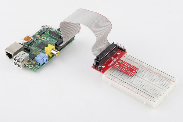
Pi and Pi Wedge

Easily access the Pi’s GPIO using the Pi Wedge.

Driving the Raspberry Pi’s I/O lines requires a bit of programming. Programming in what language? Take your pick! A quick glance at the Raspberry Pi GPIO examples shows that there are dozens of programming-language-choices. We’ve pared that list down, and ended up with two really solid, easy tools for driving I/O: Python and C (using the WiringPi library).

If you’ve never driven an LED or read in a button press using the Raspberry Pi, this tutorial should help to get you started. Whether you’re a fan of the easily-readable, interpretive scripting language Python or more of a die-hard C programmer, you’ll find a programming option that suits our needs.

Covered In This Tutorial

In this tutorial we’ll show two different approaches to reading and driving the Raspberry Pi’s GPIO pins: python and C. Here’s a quick overview of what’s covered:

  • GPIO Pinout– An overview of the Pi’s 26-pin GPIO header.
  • Python API and Examples
    • RPi.GPIO API– An overview of the Python functions you can use to drive GPIO.
    • RPi.GPIO Example– An example Python script that shows off both input and output functionality.
  • C (and WiringPi) API and Examples
    • WiringPi Setup and Test– How to install WiringPi and then take it for a test drive on the command line.
    • WiringPi API– An overview of the basic functions provided by the WiringPi library.
    • WiringPi Example– A simple example program that shows off WiringPi’s input and output capabilities.
  • Using an IDE– How to download and install Geany. Our favorite IDE for programming on the Raspberry Pi.

Each programming language has it’s share of pros and cons. Python is easy (especially if your a programming novice) and doesn’t require any compilation. C is faster and may be easier for those familiar with the old standby.

What You’ll Need

Here’s a wishlist-full of everything we used for this tutorial.

Some further notes on that bill of materials:

  • Your Raspberry Pi should have an SD card with Raspbian installed on it. Check out our How to Install Raspbian tutorial for help with that.
  • We’re also assuming you have the necessary mouse, keyboard and display hooked up to your Pi.
  • Your Pi will need an Internet connection to download WiringPi. You can use either Ethernet or WiFi (check out our Raspberry Pi WiFi tutorial for help with that.
  • The Pi Wedge isn’t quite required, but it does make life a lot easier. If you want to skip the breakout, you can instead use Male-to-Female jumpers to connect from Pi to breadboard.
  • Of course, feel free to swap in your preferred button and LEDs.

Suggested Reading

This tutorial will assume you have Raspbian installed on your Raspberry Pi. Raspbian is the most popular, well-supported Linux distribution available for the Pi. If you don’t have Raspbian set up, check out our Setting Up Raspbian tutorial before continuing down this rabbit hole.

Other, more general purpose tutorials you might be interested in reading include:

  • Pulse-Width Modulation– You can use PWM to dim LEDs or send signals to servo motors. The RPi has a single PWM-capable pin.
  • Light-Emitting Diodes (LEDs)– To test the output capabilities of the Pi, we’ll be driving a lot of LEDs.
  • Switch Basics– And to test inputs to the Pi, we’ll be using buttons and switches.
  • Pull-Up Resistors– The Pi has internal pull-up (and pull-down) resistors. These are very handy when you’re interfacing buttons with the little computer.

Suggested Viewing

Check out our Raspberry Pi video tutorials if you want a more visual introduction to the Pi!

GPIO Pinout

The majority of I/O pins on the Raspberry Pi exist on the 26-pin header labeled “P1”. It’s over in the corner of the board, adjacent to the composite video connector.

Raspberry Pi P1 location

If you’re coming to the Raspberry Pi as an Arduino user, you’re probably used to referencing pins with a single, unique number. Programming the Pi’s hardware works much the same, each pin has its own number…and then some.

There are (at least) two, different numbering schemes you may encounter when referencing Pi pin numbers: (1) Broadcom chip-specific pin numbers and (2) P1 physical pin numbers. You’re usually free to use either number-system, but many programs require that you declare which scheme you’re using at the very beginning of your program.

Here’s a table showing all 26 pins on the P1 header, including any special function they may have, and their dual numbers:

Broadcom PinFunctionP1 PinP1 PinFunctionBroadcom Pin
3.3V125V
2SDA345V
3SCL56GND
478TX14
GND910RX15
171112PWM18
271314GND
22151623
3.3V171824
10MOSI1920GND
9MISO212225
11SCLK2324CE08
GND2526CE17

Legend:5V3.3VGNDI2CSPIPWM

Note: The Broadcom pin numbers above relate to Rev2 of the Raspberry Pi only. If you have an older Rev1 Pi, check out this link for your Broadcom pin numbers.

As you can see, the Pi not only gives you access to 17 bi-directional I/O pins, but also Serial (UART), I2C, SPI, and even some PWM (“analog output”).

Hardware Setup

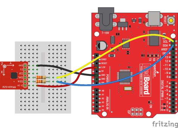
To get a head start you can assemble the circuit now. We’ll use this setup for both the C and Python examples. We’ll use two LEDs to test the output functionality (digital and PWM), and a button to test the input.

Tutorial example circuit

Our two LEDs are connected to the Pi’s pins 18 and 23– those are the Broadcom chip-specific numbers. If you’re basing your wiring off the P1 connector pin numbers, that’d be pins 12 and 16.

The button is connected to Broadcom pin 22, aka P1 pin 15.

If you have Pi Wedge, the hookup should be pretty straight-forward. It’ll look a little something like this when you’re done:

alt text

If you don’t have a Pi Wedge, male-to-female jumper wires help to make an easy transition from Pi to breadboard.

Python (RPi.GPIO) API

We’ll use the RPi.GPIO module as the driving force behind our Python examples. This set of Python files and source is included with Raspbian, so assuming you’re running that most popular Linux distribution, you don’t need to download anything to get started.

On this page we’ll provide an overview of the basic function calls you can make using this module.

Setup Stuff

In order to us RPi.GPIO throughout the rest of your Python script, you need to put this statement at the top of your file:

language:Python
import RPi.GPIO as GPIO

That statement “includes” the RPi.GPIO module, and goes a step further by providing a local name – GPIO– which we’ll call to reference the module from here on.

Pin Numbering Declaration

After you’ve included the RPi.GPIO module, the next step is to determine which of the two pin-numbering schemes you want to use:

  1. GPIO.BOARD– Board numbering scheme. The pin numbers follow the pin numbers on header P1.
  2. GPIO.BCM– Broadcom chip-specific pin numbers. These pin numbers follow the lower-level numbering system defined by the Raspberry Pi’s Broadcom-chip brain.

If you’re using the Pi Wedge, we recommend using the GPIO.BCM definition – those are the numbers silkscreened on the PCB. The GPIO.BOARD may be easier if you’re wiring directly to the header.

To specify in your code which number-system is being used, use the GPIO.setmode() function. For example…

language:Python
GPIO.setmode(GPIO.BCM)

…will activate the Broadcom-chip specific pin numbers.

Both the import and setmode lines of code are required, if you want to use Python.

Setting a Pin Mode

If you’ve used Arduino, you’re probably familiar with the fact that you have to declare a “pin mode” before you can use it as either an input or output. To set a pin mode, use the setup([pin], [GPIO.IN, GPIO.OUT] function. So, if you want to set pin 18 as an output, for example, write:

language:Python
GPIO.setup(18, GPIO.OUT)

Remember that the pin number will change if you’re using the board numbering system (instead of 18, it’d be 12).

Outputs

Digital Output

To write a pin high or low, use the GPIO.output([pin], [GPIO.LOW, GPIO.HIGH]) function. For example, if you want to set pin 18 high, write:

language:Python
GPIO.output(18, GPIO.HIGH)

Writing a pin to GPIO.HIGH will drive it to 3.3V, and GPIO.LOW will set it to 0V. For the lazy, alternative to GPIO.HIGH and GPIO.LOW, you can use either 1, True, 0 or False to set a pin value.

PWM (“Analog”) Output

PWM on the Raspberry Pi is about as limited as can be – one, single pin is capable of it: 18 (i.e. board pin 12).

To initialize PWM, use GPIO.PWM([pin], [frequency]) function. To make the rest of your script-writing easier you can assign that instance to a variable. Then use pwm.start([duty cycle]) function to set an initial value. For example…

language:Python
pwm = GPIO.PWM(18, 1000)
pwm.start(50)

…will set our PWM pin up with a frequency of 1kHz, and set that output to a 50% duty cycle.

To adjust the value of the PWM output, use the pwm.ChangeDutyCycle([duty cycle]) function. [duty cycle] can be any value between 0 (i.e 0%/LOW) and 100 (ie.e 100%/HIGH). So to set a pin to 75% on, for example, you could write:

language:Python
pwm.ChangeDutyCycle(75)

To turn PWM on that pin off, use the pwm.stop() command.

Simple enough! Just don’t forget to set the pin as an output before you use it for PWM.

Inputs

If a pin is configured as an input, you can use the GPIO.input([pin]) function to read its value. The input() function will return either a True or False indicating whether the pin is HIGH or LOW. You can use an if statement to test this, for example…

language:Python
if GPIO.input(22):
    print("Pin 2 is HIGH")
else:
    print("Pin 2 is LOW")

…will read pin 22 and print whether it’s being read as HIGH or LOW.

Pull-Up/Down Resistors

Remember back to the GPIO.setup() function where we declared whether a pin was an input or output? There’s an optional third parameter to that function, which you can use to set pull-up or pull-down resistors. To use a pull-up resistor on a pin, add pull_up_down=GPIO.PUD_UP as a third parameter in GPIO.setup. Or, if you need a pull-down resistor, instead use pull_up_down=GPIO.PUD_DOWN.

For example, to use a pull-up resistor on pin 22, write this into your setup:

language:Python
GPIO.setup(22, GPIO.IN, pull_up_down=GPIO.PUD_UP)

If nothing is declared in that third value, both pull-resistors will be disabled.

Etc.

Delays

If you need to slow your Python script down, you can add delays. To incorporate delays into your script, you’ll need to include another module: time. This line, at the top of your script, will do it for you:

language:Python
include time

Then, throughout the rest of your script, you can use time.sleep([seconds]) to give your script a rest. You can use decimals to precisely set your delay. For example, to delay 250 milliseconds, write:

language:Python
time.sleep(0.25)

The time module includes all sorts of useful functions, on top of sleep. Check out the reference here.

Garbage Collecting

Once your script has run its course, be kind to the next process that might use your GPIOs by cleaning up after yourself. Use the GPIO.cleanup() command at the end of your script to release any resources your script may be using.

Your Pi will survive if you forget to add this command, but it is good practice to include wherever you can.


Now then. Lets incorporate everything we learned here into an example script to try everything out.

Python (RPi.GPIO) Example

Follow along as we use the basic RPi.GPIO functions from the last page to create a simple example GPIO script.

1. Create a File

To begin, we need to create a Python file. You can do this through the GUI-based file explorer. Or, if you want a terminal-based solution, open up LXTerminal, and navigate to a folder you’d like the file to live (or create one). And create a new folder with these commands:

pi@raspberrypi ~/code $ mkdir python
pi@raspberrypi ~/code $ cd python

Create a file – we’ll call ours “blinker” – and terminate it with a .py extension. Then open it up in your favorite text editor. Nano works, as does Pi’s default GUI text editor, Leafpad.

pi@raspberrypi ~/code/python $ touch blinker.py
pi@raspberrypi ~/code/python $ leafpad blinker.py &

That’ll open up a blank text file (the “&” will open it in the background, leaving the terminal in place for future use). Time for some code!

2. Codify

Here’s an example sketch that incorporates everything we learned on the last page. It does a little input and output, and even handles some PWM. This assumes you’ve set up the circuit as arranged on the Hardware Setup page.

language:Python
# External module imports
import RPi.GPIO as GPIO
import time

# Pin Definitons:
pwmPin = 18 # Broadcom pin 18 (P1 pin 12)
ledPin = 23 # Broadcom pin 23 (P1 pin 16)
butPin = 22 # Broadcom pin 22 (P1 pin 15)

dc = 95 # duty cycle (0-100) for PWM pin

# Pin Setup:
GPIO.setmode(GPIO.BCM) # Broadcom pin-numbering scheme
GPIO.setup(ledPin, GPIO.OUT) # LED pin set as output
GPIO.setup(pwmPin, GPIO.OUT) # PWM pin set as output
pwm = GPIO.PWM(pwmPin, 50)  # Initialize PWM on pwmPin 100Hz frequency
GPIO.setup(butPin, GPIO.IN, pull_up_down=GPIO.PUD_UP) # Button pin set as input w/ pull-up

# Initial state for LEDs:
GPIO.output(ledPin, GPIO.LOW)
pwm.start(dc)

print("Here we go! Press CTRL+C to exit")
try:
    while 1:
        if GPIO.input(butPin): # button is released
            pwm.ChangeDutyCycle(dc)
            GPIO.output(ledPin, GPIO.LOW)
        else: # button is pressed:
            pwm.ChangeDutyCycle(100-dc)
            GPIO.output(ledPin, GPIO.HIGH)
            time.sleep(0.075)
            GPIO.output(ledPin, GPIO.LOW)
            time.sleep(0.075)
except KeyboardInterrupt: # If CTRL+C is pressed, exit cleanly:
    pwm.stop() # stop PWM
    GPIO.cleanup() # cleanup all GPIO

After you’ve typed all of that in (don’t forget your whitespace!) save.
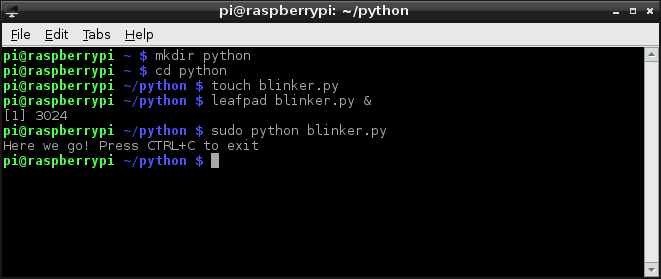
Running the Script

The RPi.GPIO module requires administrator privileges, so you’ll need to tag a sudo on to the front of your Python script call. To run your “blinker.py” script, type:

pi@raspberrypi ~/code/python $ sudo python blinker.py

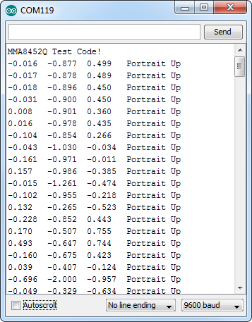
With the code running, press the button to turn on the digital LED. The PWM-ing LED will invert its brightness when you press the button as well.

Example python terminal

Press CTRL+C to cleanly exit the script.

C (WiringPi) Setup

Python is a great GPIO-driving option, especially if you’re used to it. But if you’re a rickety old programmer, unfamiliar with the whitespace-driven scripting language, and would rather live within the happy confines of C, then let me introduce the WiringPi library.

1) Install Wiring Pi

WiringPi is not included with Raspbian, so, to begin, you’ll need to download and install it. That means your Pi will need a connection to the Internet – either via Ethernet or WiFi.

Once your Pi is Internet-enabled, visit the WiringPi homepage for instructions on downloading and installing the library.

We highly recommend using Git to download the latest version. As long as you have Git installed, these commands should be all you need to download and install WiringPi:

pi@raspberrypi ~/code $ git clone git://git.drogon.net/wiringPi
pi@raspberrypi ~/code $ cd wiringPi
pi@raspberrypi ~/code/wiringPi $ git pull origin
pi@raspberrypi ~/code/wiringPi $ cd wiringPi
pi@raspberrypi ~/code/wiringPi/wiringPi $ ./build

2) Test Wiring Pi

WiringPi is awesome because it’s actually more than just a C library, it includes a command-line utility as well! You can test your installation of WiringPi with the gpio utility.

Open up a terminal, and try some of these system calls:

pi@raspberrypi ~/code $ gpio -g mode 18 output
pi@raspberrypi ~/code $ gpio -g write 18 1
pi@raspberrypi ~/code $ gpio -g write 18 0

As long as your LED is still connected to pin 18 it should blink on and off following the last two commands.

Or, to test the button, type:

pi@raspberrypi ~/code $ gpio -g mode 22 up
pi@raspberrypi ~/code $ gpio -g read 22

Either 0 or 1 will be returned, depending on whether the button is pressed or not. Try typing that last line again while pressing the button.

The gpio utility, as stated in the manual, is a “swiss army knife” command-line tool. We highly recommend checking out the man page (type man gpio) to discover everything it can do.


If you’re ready to get on with some C-style programming, head over to the next page. We’ll overview some of the most useful functions provided by the WiringPi library.

C (WiringPi) API

On this page we’ll discuss some of the most useful functions provided by the WiringPi library. It’s tailored to look a lot like Arduino, so if you’ve done any Arduino programming some of this may look familiar.

Setup Stuff

To begin, you’ll need to include the library. At the beginning of your program, type:

language:c
#include <wiringPi.h>

After you’ve included the library, your first steps should be to initialize it. This step also determines which pin numbering scheme you’ll be using throughout the rest of your program. Pick one of these function calls to initialize the library:

language:c
wiringPiSetup(); // Initializes wiringPi using wiringPi's simlified number system.
wiringPiSetupGpio(); // Initializes wiringPi using the Broadcom GPIO pin numbers

WiringPi’s simplified number system introduces a third pin-numbering scheme. We didn’t show it in the table earlier, if you want to use this scheme, check out their pins page for an overview.

Pin Mode Declaration

To set a pin as either an input or output, use the pinMode([pin], [mode]) function. Mode can be either INPUT, OUTPUT, or PWM_OUTPUT.

For example, to set pin 22 as an input, 23 as an output, and 18 as a PWM, write:

language:c
wiringPiSetupGpio()
pinMode(22, INPUT);
pinMode(23, OUTPUT);
pinMode(18, PWM_OUTPUT);

Keep in mind that the above example uses the Broadcom GPIO pin-numbering scheme.

Digital Output

The digitalWrite([pin], [HIGH/LOW]) function can be used to set an output pin either HIGH or LOW. Easy enough, if you’re an Arduino user.

To set pin 23 as HIGH, for example, simply call:

language:c
digitalWrite(23, HIGH);

PWM (“Analog”) Output

For the lone PWM pin, you can use pwmWrite([pin], [0-1023]) to set it to a value between 0 and 1024. As an example…

language:c
pwmWrite(18, 723);

…will set pin 18 to a duty cycle around 70%.

Digital Input

If you’re an Arduino veteran, you probably know what comes next. To read the digital state of a pin, digitalRead([pin]) is your function. For example…

language:c
if (digitalRead(22))
    printf("Pin 22 is HIGH\n");
else
    printf("Pin 22 is LOW\n");

…will print the status of pin 22. The digitalRead() function returns 1 if the pin is HIGH and 0 if it’s LOW.

Pull-Up/Down Resistors

Need some pull-up or pull-down resistors on your digital input? Use the pullUpDnControl([pin], [PUD_OFF, PUD_DOWN, PUD_UP]) function to pull your pin.

For example, if you have a button on pin 22 and need some help pulling it up, write:

language:c
pullUpDnControl(22, PUD_UP);

That comes in handy if your button pulls low when it’s pressed.

Delays

Slowing down those blinking LEDs is always useful – assuming you actually want to differentiate between on and off. WiringPi includes two delay functions to choose from: delay([milliseconds]) and delayMicroseconds([microseconds]). The standard delay will halt the program flow for a specified number of milliseconds. If you want to delay for 2 seconds, for example, write:

language:c
delay(2000);

Or you can use delayMicroseconds() to get a more precise, microsecond-level delay.


Now that you know the basics, let’s apply them to an example piece of code.

C (WiringPi) Example

The intention of WiringPi is to make your I/O code look as Arduino-ified as possible. However keep in mind that we’re no longer existing in the comfy confines of Arduino – there’s no loop() or setup(), just int main(void).

Follow along here as we create an example C file, incorporate the WiringPi library, and compile and run that program.

Create blinker.c

Using the terminal, navigate to a folder of your choice and create a new file – “blinker.c”. Then open that file in a text editor (Nano or Leafpad are included with Raspbian).

pi@raspberrypi ~/code $ mkdir c_example
pi@raspberrypi ~/code $ cd c_example
pi@raspberrypi ~/code/c_example $ touch blinker.c
pi@raspberrypi ~/code/c_example $ leafpad blinker.c &

The commands above will open your “blinker.c” file in Leafpad, while leaving your terminal functioning – in-directory – in the background.

Program!

Here’s an example program that includes a little bit of everything we talked about on the last page. Copy and paste, or write it yourself to get some extra reinforcement.

language:c
#include <stdio.h>    // Used for printf() statements
#include <wiringPi.h> // Include WiringPi library!

// Pin number declarations. We're using the Broadcom chip pin numbers.
const int pwmPin = 18; // PWM LED - Broadcom pin 18, P1 pin 12
const int ledPin = 23; // Regular LED - Broadcom pin 23, P1 pin 16
const int butPin = 22; // Active-low button - Broadcom pin 22, P1 pin 15

const int pwmValue = 75; // Use this to set an LED brightness

int main(void)
{
    // Setup stuff:
    wiringPiSetupGpio(); // Initialize wiringPi -- using Broadcom pin numbers

    pinMode(pwmPin, PWM_OUTPUT); // Set PWM LED as PWM output
    pinMode(ledPin, OUTPUT);     // Set regular LED as output
    pinMode(butPin, INPUT);      // Set button as INPUT
    pullUpDnControl(butPin, PUD_UP); // Enable pull-up resistor on button

    printf("blinker is running! Press CTRL+C to quit.");

    // Loop (while(1)):
    while(1)
    {
        if (digitalRead(butPin)) // Button is released if this returns 1
        {
            pwmWrite(pwmPin, pwmValue); // PWM LED at bright setting
            digitalWrite(ledPin, LOW);     // Regular LED off
        }
        else // If digitalRead returns 0, button is pressed
        {
            pwmWrite(pwmPin, 1024 - pwmValue); // PWM LED at dim setting
            // Do some blinking on the ledPin:
            digitalWrite(ledPin, HIGH); // Turn LED ON
            delay(75); // Wait 75ms
            digitalWrite(ledPin, LOW); // Turn LED OFF
            delay(75); // Wait 75ms again
        }
    }

    return 0;
}

Once you’ve finished, Save and return to your terminal.

Compile and Execute!

Unlike Python, which is an interpreted language, before we can run our C program, we need to build it.

To compile our program, we’ll invoke gcc. Enter this into your terminal, and wait a second for it to finish compiling:

pi@raspberrypi ~/code/c_example $ gcc -o blinker blinker.c -l wiringPi

That command will create an executable file – “blinker”. The “-l wiringPi” part is important, it loads the wiringPi library. A successful compilation won’t produce any messages; if you got any errors, try to use the messages to track them down.

Type this to execute your program:

pi@raspberrypi ~/code/c_example $ sudo ./blinker

The blinker program should begin doing it’s thing. Make sure you’ve set up the circuit just as modeled on the hardware setup page. Press the button to blink the LED, release to have it turn off. The PWM-ing LED will be brightest when the button is released, and dim when the button is pressed.


If typing all of that code in a bland, black-and-white, non-highlighting editor hurt your brain, check out the next page where we introduce a simple IDE that makes your programming more efficient.

Using an IDE!

Thus far we’ve been using simple text-editors – Leafpad or Nano – to write our Python and C programs. So seasoned programmers are probably missing a whole lot of features assumed of even the most basic editors: auto-tabbing, context-highlighting, even automated building. If you want to incorporate any of those features, we recommend using an IDE (integrated development environment). One of our favorite Pi IDE’s is Geany, here’s how to get it up and running.

Download and Install Geany

Geany isn’t included with Raspbian, so you’ll need an Internet connection to download it. You can use the magical apt-get utility to install it with this command:

pi@raspberrypi ~/code $ sudo apt-get update
pi@raspberrypi ~/code $ sudo apt-get install geany

Once installed, you can run Geany by going to the “Start” menu, and looking under the “Programming” tab.

Opening Geany

Or, from the terminal, you can type sudo geany. You can even open a file in Geany, directly from the command line. To open our previous C file, for example, type sudo geany blinker.c.

Using Geany…

Once Geany is running, you can create a new file by going to File > New. Saving the file as either “.c” or “.py” (or any other common language file extension) will immediately inform Geany what kind of language you’re working with, so it can start highlighting your text.

Geany can be used with most languages, including the Python and C examples we’ve just examined. Some tweaks to the default IDE options are necessary, though. Here’s an overview of using Geany with each language.

…with C and WiringPi

Let’s recreate our WiringPi Example with Geany. Open the “blinker.c” created earlier within the confines of Geany. You should immediately be presented with some very pleasant color-coding.

Geany with a C file

Before trying to compile the code, though, you’ll need to tweak some of the build options. Go up to Build and Set Build Commands. Inside the “Compile” and “Build” text blocks, tack this on to the end of the default command: -l wiringPi. That will load the wiringPi library.

Build options example

While you’re here, add “sudo” to the beginning of your execute command. Make sure your build commands look like the window above and click “OK”.

Once you’ve adjusted that setting, you should be ready to go. Click the Build menu, then click Build (or click the red cinder-block-looking icon up top). Upon building, the IDE will switch focus to the bottom “Compiler” tab, and relay the results of your compilation. If the build was successful, go ahead and run with it.

To run your built file, click Build>Execute (or click the gear icon up top). Executing will bring up a new terminal window, and start your program running. You can stop the program by pressing CTRL+C in the terminal window.

…with Python

You can also use Geany with Python. To test it out, go ahead an open up the “blinker.py” file we created earlier. As with the C file, you’ll be greeted with some pleasnt context highlighting.

Geany with a Python file

No building required with Python! Once you’re script is written, simply click the “Execute” gear up top. Again, running will produce a separate terminal to pop up. To exit, simply press CTRL+C.


Geany has tons of features beyond what we’ve covered here. Check out the tabs at the bottom. Check out the menus up top. Experiment and see how the IDE can make your programming life easier!

Resources & Going Further

Now that you know how to blink your Pi’s LEDs, check out some of these resources for going further:

  • RPi Low-level peripherals– A Wiki with tons of details on using the Raspberry Pi’s GPIO peripherals.
  • WiringPi Hompeage– The home of WiringPi and a variety of other Raspberry-Pi-related tools. Check it out!
  • RPi.GPIO Homepage– Home of the Raspberry Pi GPIO python module. Great source for API and documentation.

If you’re looking for some project inspiration, here are some more SparkFun tutorials where you’ll be able to leverage your newfound Pi programming skills:


learn.sparkfun.com |CC BY-SA 3.0 | SparkFun Electronics | Boulder, Colorado

Pi Wedge Hookup Guide

$
0
0

Pi Wedge Hookup Guide a learn.sparkfun.com tutorial

Available online at: http://sfe.io/t236

Introduction

The Raspberry Pi seems to be popping up all over the place. It’s a small, inexpensive board with a lot of number-crunching capability. It can run a standard Linux distribution, and supports a lot of common Linux applications, including programming languages like C, C++and Python. This makes it very useful for tasks that need more horsepower than a small 8-bit microcontroller provides, or that can take advantage of the feature-rich environment that Linux offers.

Raspberry Pi

The Raspberry Pi

After building several projects using the Raspberry Pi, we found some growing pains in building prototypes that incorporated external hardware. The Pi Wedge is a small board that connects to the GPIO connector, and breaks the pins out into rows that work with solderless breadboards.

Raspberry Pi and Breadboard

Pi, Pi Wedge and Breadboard

This guide will show you how to assemble the Pi Wedge, and start using it with your Raspberry Pi.

Required Materials

Suggested Reading

Suggested Viewing

Background

In the process of developing projects like the Twitter Monitor and Great American Tweet Race around the Raspberry Pi, we found that we were experiencing some growing pains when trying to expand the Pi into a prototype that involved external hardware.

Bob Pease would be proud

There’s a Pi somewhere in this ratsnest

The Raspberry Pi has a 26-pin connector that provides access to several communication interfaces, plus GPIO and power. But the connector doesn’t have detailed labeling, and the native pin arrangement is somewhat scattershot. Pins used for similar functions aren’t always grouped together, and power and ground pins are interspersed with no obvious pattern.

The pins also don’t translate to a solderless breadboard very easily. Our first projects used a bunch of F-M jumper wires that we just plugged into the header. They involved a lot of “ratsnest jiggling” when things stopped working.

Bootstrapping

In addition to the physical issues of using the I/O connector, getting started with a brand new Raspberry Pi always seems to involve a chicken-and-egg situation. We just want to SSH into it, so we can use the command line. But in order to SSH to it, we need to know it’s IP address…and of course, the IP address is most easily learned by running ifconfig on the command line.

The Solution

The Pi Wedge

Meet the Pi Wedge

The Pi Wedge connects to the 26-pin GPIO connector, and breaks out the pins in a breadboard-friendly arrangement and spacing. It even adds a pair of decoupling capacitors on the power supply lines, and it makes the initial bringup process easier - you can plug an FTDI Basic module into the serial port.

Assembly

The Pi Wedge comes to you as loose parts, which you need to assemble before you can use it. The following steps will guide you through the assembly process.

Kit Contents

Let’s start by reviewing the contents of the Pi wedge kit.

Pi Wedge parts

You should have the following parts.

  • Ribbon cable
  • Pi Wedge PCB
  • 26-pin shrouded header
  • 6-pin straight header
  • 2x 12-pin straight headers
  • 2x 10 uF 25V electrolytic capacitors

Instructions

Assembly of the Pi Wedge should be mostly obvious and straightforward. One thing to notice is that components are soldered to both sides of the board. The headers that interface with the breadboard are on the bottom of the board, soldered from the top. The other components go on the top, and are soldered from the bottom.

Pin Alignment

To keep the breadboard pins properly spaced and aligned while you solder, you can use your breadboard as an assembly jig. Simply insert the 12-pin headers in the breadboard…

Pins in breadboard

…then place the PCB over them, and solder it in place. Notice that the PCB is placed over the pins so that the signal labels are facing up.

Add the PCB

Be careful not to overheat and melt the breadboard while soldering the pins on. Zig-zagging between the rows will help distribute the heat. Also, somewhat counter-intuitively, using a hotter setting on your soldering iron will allow you to work more quickly, minimizing the risk of melting the breadboard.

Shrouded Header

The shrouded header has a notch that keeps the ribbon cable properly oriented. The notch should be lined up with the corresponding rectangle in the PCB silkscreen.

Header Alignment

Capacitors

The electrolytic capacitors are polarized. The body has a band of “-” signs near the negative lead, which should be inserted into the PCB hole marked with the - sign. The negative lead is also shorter than the positive lead.

Capacitors

Serial Adapter Connector

The 6-pin header is soldered onto the PCB across from the capacitors.

Serial Port Connector

If you want a lower profile assembly, you can substitute a right-angle header for the straight pins in the kit.

Connection

With the wedge soldered together, you’re ready to attach it to your Pi, and test it out.

The ribbon cable is polarized. On the Pi Wedge, the tooth on the cable will interface with the notch in the shrouded header.

The header on the Pi itself doesn’t have anything to help guarantee the alignment. You’ll need to take care that it gets connected properly. Pin 1 on the Pi is marked with a small rectangle in the silkscreen layer. The ribbon cable connector is embossed with (a barely visible) small triangle that marks pin 1, and the first pin is also coded on the wire, such as the red stripe in the photo below (though it may also be another color, such as black or dark blue).

Ribbon Cable Orientation

Proper pin-1 orientation

The FTDI connector also needs to be aligned correctly. Be sure to match up the “grn” and “blk” markings on both boards.

FTDI Orientation

Proper FTDI-basic orientation

On the next page, we’ll explore how the signals from the Pi are mapped to the Wedge.

Pin Mapping

Revisions

The pins on the Raspberry Pi changed between Revision 1 and Revision 2 - a few signals were reassigned. The physical connection is the same, but you’ll need to know which version of Pi you’re using to address the pins correctly.

The Wedge is labeled with the Revision 2 labels. You’ll need to translate a few things if you’re using a Revision 1 Pi. In short - to use the Wedge with a Revision 1 Raspberry Pi, do the following.

  • Be sure to use /dev/I2C0 instead of /dev/I2C1.
  • Use GPIO 21 instead of GPIO 27.

Alternately, use a software library such as Wiring Pi that can identify the revision and abstract the pin numbers. We’ll cover WiringPi in more detail in the software section.

Signal Location

The Pi Wedge reorganizes the I/O pins on the Pi, putting similar functions on adjacent pins. The SPI, I2C and UART signals are all grouped near each other.

Pin function diagram

Functional Groupings

The pins are labeled, though the labels are short to fit the space available on the PCB. The UART, SPI and I2C pins are marked with their communication bus functions, but they can also available as GPIO pins when initialized in that mode.

The following table denotes the assignment of signals on the Pi Wedge, including the peripheral and alternate GPIO assignments where appropriate.

FunctionGPIO#FunctionGPIO#
GroundR0: SCL0
R1: SCL1
R0: GPIO1
R1: GPIO3
SPI0 Chip Enable 1GPIO 7R0: SDA0
R1: SDA1
R0: GPIO0
R1: GPIO2
SPI0 Chip Enable 0GPIO 8R1: GPIO 21
R2: GPIO 27
SPI0 MOSIGPIO 10GPIO 25
SPI0 MISOGPIO 9GPIO 24
SPI0 Shift ClockGPIO 11GPIO 23
UART RxGPIO 15GPIO 22
UART TxGPIO 14GPIO 18
GPIO 4GPIO 17
5V5V
3.3V3.3V
GroundGround

Power And Logic Levels

Power

Understanding the Pi’s power supply is critical to using it successfully.

Consulting the Raspberry Pi schematic, we see that 5V comes into the the board via connector S1 - it’s a micro USB connector, but only the power and ground pins are connected. The 5V coming from this connector passes through a fuse, then continues around the board without any further regulation. The 5V connections on the Pi Wedge come straight from this line.

On the Pi, the 5V goes to a set of daisychained regulators that further reduce it to 3.3v, 2.5V and 1.8V. The regulated 3.3V is present on the I/O connector.

Pi Power Regulation

To power small circuits on your breadboard, you can run jumpers from the 5V or 3.3V and Ground pins on the wedge to the power rails on the breadboard.

Power Rails

Jumpering power to the breadboard rails

Be aware that there’s not a lot of juice available from the Pi. The Pi foundation states that the max draw from the 3.3V pins is 50 mA. In our experience, that’s not a lot. When we built a display with a string of alphanumeric LED modules, we reached the point that turning on too many LED segments caused the CPU to reboot.

Similarly, the current available on the 5V pins is constrained by the fuse and limits of the attached USB port.

If you want to drive a lot of circuitry from a Pi, you’ll need to use a more robust power distribution scheme. One example would be to use an external power supply, connected directly to each portion of the system. For peripherals that use 5V logic, it would also involve logic level translation.

Star Power Diagram

The peripherals are powered from the supply directly

Logic Levels

The Pi uses 3.3V logic levels, which are not 5V tolerant. Many peripheral devices are capable of running at 3.3V, but in the case that you need to interface with 5V devices, use a level shifter, such as the TXB0104 breakout.

Communications

Finally, the signals on the 6-pin FTDI header are also limited to 3.3v logic levels. Be sure to use it with a 3.3V FTDI module, and not a 5V one.

Software

With the many programming languages available on the Pi, it’s hard to know where to start writing software that interfaces with the I/O connector.

As a quick and easy way to check out the connections on the IO connector, check out the WiringPi package. Wiring Pi is a hardware interface library that includes a utility to help you configure and check the status of the GPIO connector pins.

Follow these instructions to install Wiring Pi.

Once you’ve got it installed, you can use the gpio command line utility to quickly check and test hardware connections.

gpio takes a number of arguments. The readall option prints a handy table that deciphers the configuration and assignment of the pins. It also detects the revision of the Pi, and translates the pin numbers to match.

user@raspberrypi:~/wedgetest$ gpio readall
+----------+-Rev2-+------+--------+------+-------+
| wiringPi | GPIO | Phys | Name   | Mode | Value |
+----------+------+------+--------+------+-------+
|      0   |  17  |  11  | GPIO 0 | IN   | Low   |
|      1   |  18  |  12  | GPIO 1 | IN   | Low   |
|      2   |  27  |  13  | GPIO 2 | IN   | Low   |
|      3   |  22  |  15  | GPIO 3 | IN   | Low   |
|      4   |  23  |  16  | GPIO 4 | IN   | Low   |
|      5   |  24  |  18  | GPIO 5 | IN   | Low   |
|      6   |  25  |  22  | GPIO 6 | IN   | Low   |
|      7   |   4  |   7  | GPIO 7 | IN   | Low   |
|      8   |   2  |   3  | SDA    | IN   | High  |
|      9   |   3  |   5  | SCL    | IN   | High  |
|     10   |   8  |  24  | CE0    | IN   | Low   |
|     11   |   7  |  26  | CE1    | IN   | Low   |
|     12   |  10  |  19  | MOSI   | IN   | Low   |
|     13   |   9  |  21  | MISO   | IN   | Low   |
|     14   |  11  |  23  | SCLK   | IN   | Low   |
|     15   |  14  |   8  | TxD    | ALT0 | High  |
|     16   |  15  |  10  | RxD    | ALT0 | High  |
|     17   |  28  |   3  | GPIO 8 | ALT2 | Low   |
|     18   |  29  |   4  | GPIO 9 | ALT2 | Low   |
|     19   |  30  |   5  | GPIO10 | ALT2 | Low   |
|     20   |  31  |   6  | GPIO11 | ALT2 | Low   |
+----------+------+------+--------+------+-------+

Somewhat confusingly, you’ll notice that the first 3 columns of that table are all different numbers, each a different way to refer to the pins on the Pi. The “wiringPi” column is a set of contiguous numbers that WiringPi uses by default. The “GPIO” comumn uses the GPIO channel numbers as assigned within the BCM2835 processor. The “phys” column corresponds to the pin number of the P1 connector on the Pi.

The Pi Wedge is labeled with the numbers seen in the GPIO column.

If you run gpio without any parameters, it displays the available options. You can use it to configure, read and write pins right from the command line. Similarly, man gpio displays more detailed information on using the utility, including a number of sample commands.

Programming

If you’re coming from Arduino, and you’ve got a handle on how it manages I/O, you’ll find that the WiringPi libraries present a familiar programming interface. We have a few WiringPi based examples in the Pi Wedge GitHub Repository that should help you get started.

If Python is more your speed, then take a look at the RPi.GPIO module.

For more detailed information about using both WiringPi and RPi.GPIO, take a look at our Raspberry gPIo tutorial.

Resources & Going Further

Going Further

To take a closer look at programming for the I/O on a Pi, in both Python and C, take a look at our Raspberry gPIo tutorial.

Resources

For more information about the Raspberry Pi and the software described here, please visit their sites.

If you have any problems or questions, our technical support department can help. Please don’t hesitate to contact us. We also love to hear about your projects!


learn.sparkfun.com |CC BY-SA 3.0 | SparkFun Electronics | Boulder, Colorado

CryptoCape Hookup Guide

$
0
0

CryptoCape Hookup Guide a learn.sparkfun.com tutorial

Available online at: http://sfe.io/t231

What is a CryptoCape?

alt text

The CryptoCape is a collaboration with Hacker In Residence alumni Josh Datko. The CryptoCape is the BeagleBone’s first dedicated security daughterboard. Known as “shields” on other platforms, a BeagleBone cape attaches to the expansion headers of the BeagleBone Black. This cape adds specialized ICs that perform various cryptographic operations which will allow you to add a hardware security layer to your BeagleBone project. It also is a nice device for those performing embedded security research.

In this tutorial, we’ll tour the features on the CryptoCape and show you the software resources available for you to start using the device.

Required Materials

Aside from the CryptoCape, you’ll also need the following items:

Suggested Reading

Before getting into this tutorial, make sure you’re familiar with the concepts below:

Installing the Cape Firmware

The CryptoCape is a registered BeagleBone cape whose firmware is included in the latest BeagleBone debian images. However, you may have to upgrade your image to retrieve the latest software. Perform the following command on your BeagleBone:

dmesg | grep CRYPTO

If you see something like this, then you have the firmware installed:

[    0.717065] bone-capemgr bone_capemgr.9: slot #3: 'BB-BONE-CRYPTO,00A0,SparkFun,BB-BONE-CRYPTO'
[    0.717766] bone-capemgr bone_capemgr.9: loader: before slot-3 BB-BONE-CRYPTO:00A0 (prio 0)
[    0.717783] bone-capemgr bone_capemgr.9: loader: check slot-3 BB-BONE-CRYPTO:00A0 (prio 0)
[    0.720127] bone-capemgr bone_capemgr.9: loader: after slot-3 BB-BONE-CRYPTO:00A0 (prio 0)
[    0.720149] bone-capemgr bone_capemgr.9: slot #3: Requesting part number/version based 'BB-BONE-CRYPTO-00A0.dtbo
[    0.720167] bone-capemgr bone_capemgr.9: slot #3: Requesting firmware 'BB-BONE-CRYPTO-00A0.dtbo' for board-name 'BB-BONE-CRYPTO', version '00A0'
[    0.720196] bone-capemgr bone_capemgr.9: slot #3: dtbo 'BB-BONE-CRYPTO-00A0.dtbo' loaded; converting to live tree
[    0.756311] bone-capemgr bone_capemgr.9: loader: done slot-3 BB-BONE-CRYPTO:00A0 (prio 0)

You still need to install tpm-tools to use the TPM.

If you don’t see the CryptoCape in dmesg, perform the following:

sudo apt-get install tpm-tools
cd /opt/scripts/tools/
sudo ./update_kernel.sh
sudo reboot

If you don’t have an /opt/scripts/tools directory, then you have a really old version of sofware on your Beagle and you need to upgrade. Download the latest image from the BeagleBoard.org site.

Cape EEPROM

alt text

The Cape’s EEPROM is defaulted to an I2C address of 0x57. If you plan on stacking capes – the BeagleBone can support up to four stacked capes – you may need to change the addresses of the EEPROM. The table below contains the available addresses for the EEPROM. Close the appropriate jumpers to change the address. (0 - Closed, 1 - Open).

Address Table

A2 A1 A0 7-bit address
100
0x54
101
0x55
110
0x56
111
0x57

If you want to prevent users from writing to the EEPROM, you’ll need to solder 0.1" male headers to the write protect pads and place a jumper on these pins. The EEPROM contains the cape definition, which is written during manufacturing and testing. If you overwrite it, the cape may not load correctly. You can always read the EEPROM with the following command:

sudo cat /sys/bus/i2c/devices/1-0057/eeprom| hexdump -C

Real Time Clock

alt text

The Real-Time Clock is used to keep accurate time. The driver for the DS3231M RTC will be loaded automatically with the rest of the cape firmware. If you add a coin cell battery to the battery holder, the RTC will keep time even when power is removed from the BeagleBone.

For a closer look at how to use the RTC and how I2C works on the BeagleBone Black, checkout this tutorial.

Trusted Platform Module

alt text

The Atmel Trusted Platform Module (TPM) is the AT97SC3205T, and only a summary datasheet is available with an NDA. However, the full datasheet is not required because there is existing software support. The TPM conforms to the Trusted Computer Group (TCG) Software Stack (TSS) Specification version 1.2, which is supported by the TrouSerS Linux software.

A very generic description of the TPM is that it performs RSA encryption, decryption, and signing in the hardware. It can perform much more than that, and there are entirebooks on how to use the TPM.

The kernel driver was backported to the 3.8 kernel by Robert Nelson of BeagleBoard.org and will be loaded automatically by the BeagleBone Cape Manager.

Using the TPM

Instructions for using the TPM are located on this page.

AES-128 EEPROM

alt text

The Atmel AES132 is an AES encrypted EEPROM that can store up to 32Kb of data. Specifically, it uses AES with a 128 bit key in CCM mode.

There currently is not a linux driver that uses this hardware, however you can use the Atmel AES132 AVR software. As with the other crypto chips, once you run the lock command, this is an irreversible operation.

ATSHA204

alt text

The Atmel ATSHA204 is an authentication chip that performs SHA-256 and HMAC-256. It can store up to 16 secret keys that can be used for shared-secret authentication between two devices with an ATSHA204 or between a ATSHA204 and a remote server. It also can produce random numbers with its on-chip random number generator. The ATSHA204 on the CryptoCape is the I2C version of our Breakout Board version. It’s also on the Electric Imp.

This chip, like the other crypto chips, is one-time-programmable. This means that once you run certain commands on the chip, it can not be reversed. This is a security feature.

Software

There are two options for software, you can use either Atmel’s AVR library and load that to the ATmega328p, or you can use the Cryptotronix linux driver.

Atmel’s AVR Library

Atmel’s ATSHA204 AVR Library page hash links to their software.

Cryptotronix Linux driver

The linux driver, called hashlet, can be download here or cloned from GitHub. See the GitHub page for examples.

Elliptical Curve Generator

alt text

The ATECC108 performs the Elliptic Curve Digital Signature Algorithm (ECDSA) on the chip. This is an authentication chip, like the ATSHA204. The goal of an authentication device is to assert the integrity and identity of a communicating party. The ATECC108 uses asymmetric cryptography, which means there is a public and private key. In short, this allows you to distribute public keys and keep individual private keys secret. This is unlike the ATSHA204 where each device needs a copy of the same secret key.

Atmel AVR Library

While the datasheet is under a NDA, Atmel provides an AVR based library to interface with this chip.

Linux Driver

There is a Cryptotronix Linux driver, with examples, available on GitHub. This blog post walks through using the software and describes the current status.

Atmega 328

alt text

The ATmega328p operates at 3.3V and 8Mhz, just like the Arduino Pro Mini. It is loaded with the Arduino Pro Mini 3.3V bootloader and contains a basic test sketch from the factory. There are two ways to upload sketches to this chip: Using an ISP programmer or from the BeagleBone.

Using an external programmer

The Pocket AVR Programmer will work to program the ATmega. You’ll need to populate the ISP headers with some 0.1" male headers. When you connect the Pocket Programmer, be sure to select “No Power” because the CryptoCape receives 3.3V power from the BeagleBone. While most of the chips on this board are 5V friendly, the oscillator for the TPM is not. You can then use the USBTiny programmer option from the Arduino IDE.

Using the BeagleBone

Since the ATmega is tied to the BeagleBone’s UART4, the BeagleBone can flash sketches up to the ATmega. If you want a detailed description of how this works, check out the May 2014 cover article of Linux Journal. You’ll not only see how to program the ATmega, you’ll read how the device tree works in gory details.

For those that just want to upload sketches quickly, clone the following repository from your BeagleBone:

git clone https://github.com/jbdatko/BBB_ATmega328P_flasher.git

In that repository, there is an upload.sh script, which is invoked as follows:

sudo ./upload Blink.cpp.hex

Replace Blink.cpp.hex with the hex file you want to flash. How do you get this hex file? In your Arduino IDE, go to “Preferences” then “Show verbose output during compilation.” When you “verify” your sketch, the output window will tell you where the hex file lives. Download this to the BeagleBone with sftp or something similar.

Installing the Jumpers

alt text

Jumpers Installed

To flash the ATmega from the Beagle, you must physically attach jumpers to the “Program Jumper” pads. You should solder 0.1" male headers to these pads. The spacing between these jumpers is purposely oddly spaced to prevent you from attaching the jumpers in the wrong direction. Without the jumpers, you can’t upload sketches from the Beagle.

This is a security feature. We wouldn’t want some malware changing the firmware on the ATmega, now would we?

Breakout Pads

The CryptoCape breaks out most of the ATmega signals to surrounding pads. There is even a green LED which is compatible with the typical “Blink” sketch, so you can upload that example to make sure everything is working. Not all the Arduino signals are broken out, but the ones that are available on the CryptoCape are listed here:

  • GND
  • 3.3V
  • D0 - D10
  • D13 with LED
  • A0 - A13

The serial UART between the BeagleBone and the ATmega can be split. If you don’t put the jumpers on, the serial line will not be connected, and the BeagleBone can use the “upstream” side of the serial lines while the ATmega can use the “downstream.” This might be useful if you have two serial devices and you want the BeagleBone to talk to one of them and the ATmega to the other, without mixing the signals.

I2C

The ATmega is connected to the same I2C bus as all of the other chips. This means you can join the bus as an I2C slave with Wire.begin(address) and communicate with the Beagle over I2C. Just be sure to pick an address not already in use. We recommend 0x42, because it’s the answer to life, the universe, and everything. But if you attached the HMC6352, you’ll need a new address since that is also 0x42.

This blog post contains a detailed overview of using I2C on the BeagleBone Black.

Resources and Going Further

There is a dedicated CryptoCape Google Group if you have specific questions. Also, feel free to join the #cryptotronix channel on Freenode. While you are joining IRC channels, hang out in the SparkFun IRC channel as well!

Further reading:


learn.sparkfun.com |CC BY-SA 3.0 | SparkFun Electronics | Boulder, Colorado

Teardown: DDC Mobile X900

$
0
0

Teardown: DDC Mobile X900 a learn.sparkfun.com tutorial

Available online at: http://sfe.io/t251

Latest and Greatest

alt text

On a recent trip to China, our fearless leader encountered a very special mobile device. It has a shape like none other, It’s in a weight class of its own, and it has a camera and flashlight that you normally wouldn’t find on a cellphone. On top of all that, it’s solid like a… well… like a brick. And as we took it apart we were greeted by all kinds of surprises!

Join me as I find out what space-age technology is hidden within this mighty chunk of phone!

"Features" and "Accessories"

Before we tear into this beauty, let’s take a moment to explore the bells and whistles. The box advertises large “streo” speakers and a strong flashlight that “can as 30 meters.” Not only that, but it “suppore Multi-languagse,” and, most importantly of all: “ sbook.”

Pop open the box and you’re presented with the following:

alt text

On the left, you’ll notice this phone comes with its own very sporty headset. Featuring two hard plastic earbuds, something vaguely microphone shaped and a buttonesque protrusion. Whereas many phones would try to squeeze all of this functionality through a useless audio jack, the X900 rather cleverly (mis)uses a USB mini-B connector.

You may be thinking, at this point, “if that USB mini-B port is for the headset then how do I charge it?” No worries! Provided you have access to a wall outlet and the proper adapters for your country, the included charger fits snugly into the tiny barrel jack connector just above the USB port.

And finally we come to the phone:

alt text

I can hear you. You’re saying, “Please tell me that’s a massive, but somewhat dim, LED flashlight.” Oh, you’re darn skippy it is. And turning it on is as easy as pressing the “Unique flashlight push switch” into the on position or, one imagines, leaving the phone in your purse or pocket.

Just below that, you’ll notice a full-on USB-A charging port. Not so you can charge the phone but so that the phone can charge other things… not a bad trick if you have the battery to back it up. Speaking of which, let’s have a look at that battery:

alt text

Sliding off the back cover, you notice that the battery is a massive brick. You’re quickly distracted, however, by the strange mess underneath:

alt text

Oh yes. Two SIM card slots and one SD storage slot. This is a spy phone, for sure, just like 007 might carry. But finally I think it’s time to get to the important part: the operating system.

alt text

Okay, it isn’t without its quirks but a little bit of exploration will turn up the games directory:

alt text

The phone comes with only one game, because you only need one game. And that game is… well, I don’t really know what it’s called or how to play it. It features a Panda that doesn’t like bugs one single bit:

alt text

Okay, enough of this. There must be more to this phone and the only way to find out is to get it open!

Heavyweight Chump

The first thing that you’ll notice when you pick up an X900 is the immense weight. This phone feels solid, and parts of it really are. But where is all of that weight coming from? Let’s find out:

alt text

As you can see, the phone and battery together weight a whopping 8.45 ounces. By comparison, the iPhone 5s in its entirety weighs only 3.95 ounces. Perhaps this weight discrepancy can be explained by the massive “8000 mAh” battery brick:

alt text

Uh… hmm… Let’s start pulling the phone apart then and see if maybe the unusually large and capable flashlight is responsible for the added mass:

alt text

Well it isn’t in there… But wait that only leaves one place that the weight could be hiding…

alt text

That’s right. The front panel of the X900 is cast from pot metal and weighs, on its own, a quarter of an ounce more than the iPhone 5s. This isn’t looking good. In fact, now that I think about it that battery seems really light. What was the capacity on that thing?

alt text

Well, it says 8800mAh at 3.7V but I’ve handled quite a few batteries and I just don’t see that being true. Normally, I wouldn’t advise tearing into a cellphone battery but I had a really good feeling that as soon as the sticker was torn away I might be presented with… well… this:

alt text

That’s an 18650! It’s a common cylindrical Li-ion battery, it is indeed rechargeable, but it packs only 2000mAh. That’s less than a quarter of the advertised capacity.

alt text

Close enough.

Let’s dig a little deeper, this is getting interesting…

The Naughty Bits

alt text

Now that we know the dumb bit on the right is much much heavier than the smart bit on the left, let’s find out just how smart that “smart bit” is.

alt text

After snipping a few wires, the main board of the phone frees itself from the frame without much trouble. You’ll notice that the main board is wired to all sorts of things including the antenna, the flashlight and the USB charging port using some flimsy bits of wire. It’s worth mentioning at this point that the flashlight is really just an LED with some heatsink material behind it wired directly to the power rail through a slide switch.

alt text

If this is the speaker that the box brags about then the box is half right. It’s a ‘large speakers’ but it is most definitely not a ‘streo speakers.’ Let’s flip it and check out the keypad.

alt text

That’s definitely a pretty standard keypad, but wait a second… what’s this underneath?

alt text

What the heck? It’s a secret keypad. I told you this was some kind of spy phone. I’m assuming what happened is that the fine folks at DDC Mobile bought a bunch of phone boards and a bunch of rubber keypads but they weren’t compatible… so they had to stuff in another board to match them up.

alt text

So… there’s a sticker. I was really hoping it would hold some clues for me but I don’t know how to decipher this at all. This is V2.0 of the board, though, so there must have been one worse. That’s progress of a sort.

Bag of Chips

I guess we’ve seen the dirty truth, but we can’t know the whole story until we get a handful of datasheets. Let’s start looking for part numbers:

alt text

Found one! The silkscreen on this camera module turned up the datasheet for an image sensor called the GC6123. An image sensor that must be in demand these days with its whopping 240x320 pixel resolution. That’s a small fraction of a megapixel!

alt text

Ah ha! The brains of the operation! Both of the ICs pictured above are made by the same company: RDA microelectronics. This is the first time I’ve ever had trouble searching for a datasheet because the part number brought back more forums than anything. Forums full of people trying to get tools and firmware to reprogram the chips in order to make cheap phones and clone IMEIs. Apparently, the RDA8851C is a very popular controller in these inexpensive Chinese cellphones. And why wouldn’t it be? Integrated flash on chip, camera interface, keypad scanner, quad-band integrated transceiver… in a way, this thing is the phone.

The only component that doesn’t seem to be integrated? The front-end RF module. That’s where the RDA6625 steps in.

Okay, we kind of get how the phone works now but let’s revisit the battery. Truth be told, that 18650 wasn’t the only thing in the battery enclosure. I also found this:

alt text

A board containing a pair of battery protection ICs:

The S8205, which protects multiple cells from overcharge, over-discharge and over-current.

And the DW01 which seems to do exactly the same thing only for a single cell… which this is. This leads me to believe that the battery board is used in multiple batteries, you’d probably find the same board in 40% of li-po batteries in China.

Well That Was Weird

alt text

So there you have it. The X900 is a cheap quad-band phone from China. It’s made by a company called DDC, apparently from parts of other cell phones, and badged “Nokia.” Literally half of the weight of the device is the faceplate and the battery is only a quarter of advertised capacity. But you know what?

I like it.

It makes me feel like I could build a cellphone if I really wanted to. In fact, I may take the guts of this phone and turn it into a reasonably sized device. I went so far as to put an AT&T SIM card in the phone and it works fine! If all you need is a cellphone with no frills and the weight and shape of a Motorola brick phone… the X900 is for you.

Datasheets:


learn.sparkfun.com |CC BY-SA 3.0 | SparkFun Electronics | Boulder, Colorado

XBee Shield Hookup Guide

$
0
0

XBee Shield Hookup Guide a learn.sparkfun.com tutorial

Available online at: http://sfe.io/t230

Introduction

The XBee Shield gives your Arduino a seamless interface to XBee– one of the most popular wireless platforms around. With XBee, instead of being tied down by a serial cable – inches away from a paired device – your Arduino can pass data over the air to another device hundreds of feet away.

XBee Shield Action Shot

Part of what makes XBee so popular is its simplicity. XBees are controlled over a serial interface– in the most basic operation they can be used as a wireless serial cable. Setting up XBee networks and addresses is also simplified with Digi’s free software – XCTU – which we explain in a separate tutorial.

Covered In This Tutorial

The goal of this tutorial is to set up wireless XBee communication between a computer and an Arduino/XBee Shield combo. Then, using a terminal program, we can remotely send data to an Arduino, or read data off of it.

Communication example

We’ll begin by examining the schematics and hardware of the XBee Shield, then move on to example code. First we’ll set up a test program to make sure our XBees are communicating with each other. Then we’ll move on to the remote control Arduino sketch.

Materials Required

  • 1x XBee Shield– The star of this tutorial.
    • You’ll also need headers to install into your shield. We recommend stackable headers.
  • 1x Arduino– The XBee Shield should work with any Arduino-compatible board – Uno, RedBoard, Mega, you name it.
  • 2x XBees– XBees exist in a variety of series, frequencies, and ranges. If you’re just getting started with XBee, we highly recommend going with Series 1 models – either with a trace antenna, wire antenna or u.fl connector.
  • 1x Explorer– The Explorer board allows you to connect an XBee to your computer. You can use either the Explorer USB, Explorer USB Dongle, or Explorer Serial.
  • At least one computer with X-CTU installed.
    • The latest version of X-CTU is available for both Mac and Windows!
  • Soldering tools to install headers into your shield. The most basic of irons and solder should do.

Suggested Reading

Before reading through this tutorial, we highly recommend checking out the Exploring XBees and XCTU tutorial. That tutorial will introduce you to XCTU and explain how to configure XBee networks and addresses.

In addition to that tutorial, we also recommend checking these guides out:

  • Serial Communication– Serial communication is critical to controlling and managing XBees.
  • Arduino Shields– The basics of Arduino Shields, including how to assemble a shield.
  • XBee Buying Guide– We highly recommend Series 1 XBee’s, if this is your first time playing with them. If you’re curious about other XBee classes, check out this guide!

Hardware Overview

Here’s a quick overview of the most components of the XBee Shield:

Annotated XBee Shield

Below we’ll go more in-depth on the most important components of the shield.

UART/SoftwareSerial Switch

One of the most important components on the XBee Shield is the DLINE/UART switch. This switch controls which Arduino pins interface with the XBee.

alt text

The Arduino Uno has a single hardware UART, which is usually either used for programming (via the Arduino’s serial bootloader) or communication with the serial monitor. That serial port can only be used to communicate with one device at any time, lest you run into problems of bus contention. There’s also a chance that, during program upload, spurious – even harmful – data might be sent to any device attached to the Arduino’s hardware UART.

So to avoid any problems that might arise from connecting the XBee to the Arduino’s hardware UART, we usually take advantage of the Software Serial library, connecting the XBee’s RX and TX pins to a pair of free digital pins on the Arduino.

To select between software and hardware serial, the XBee Shield includes a small, surface-mount slide switch. This switch allows you to select between the hardware serial port (UART position) and a software serial port connected to pins 2 (Arduino-side TX) and 3 (Arduino-side RX).

alt text

The switch configuration from the XBee Shield schematic. “D_TX” connects to Arduino pin 3, and “D_RX” connects to Arduino pin 2.

For all of our example sketches we’ll assume the switch is in the DLINE position. At the very least, make sure the switch is in the “DLINE” position when uploading sketches.

LED Indicators

There are 5 LEDs on the XBee Shield. Each of these LEDs connects to a pin on the XBee, which does most of the LED driving. Here’s a table explaining the operation of each LED:

LED LabelLED ColorXBee Pin ConnectionDefault Operation Notes
PWRRed3.3VIndicates power is present.
DIO5GreenAssociate/DIO5Associated indicator -- blinks when the XBee is associated with another XBee.
DOUTRedDOUTIndicates wireless data is being received.
DINGreenDINIndicates wireless data is being transmitted.
RSSIGreenPWM0/RSSIIndicates relative signal strength (RSSI) of last received transmission.

These LEDs can be very useful for debugging. The DIO5/Associate indicator should blink when the XBee is paired with a compatible device. The RSSI LED is actually PWM’d so it will be brighter when the paired XBee is closer (sending a stronger signal).

Assembly Tips

Before you can use the XBee Shield with your Arduino, you’ll need to solder in some headers.

alt text

Check out the assembly page of our Shield tutorial for all of the tips and tricks related to header installation.

XBee Socket

There is some white silkscreen on the Shield PCB to help orient your XBee as you’re plugging it in. Make sure to match up the XBee’s two diagonal edges with the two diagonal lines on the PCB.

alt text

With everything installed, you’re ready for the next step! Time to code…

Example: Communication Test

Lets start simple. In this section we’ll upload a sketch which passes data between your serial monitor and the XBee. This sketch can be use to create a “portal of communication” between your Arduino’s serial monitor, and another XBee (connected to a computer via a USB Explorer).

Double-Check Your XBee Network

Before continuing with this example, you’ll need to make sure your XBee’s are configured correctly – they need to be on the same network and have compatible destination and MY addresses. By default, XBees will all be compatibly configured, but we recommend setting up unique network ID’s and addresses. Check out the Configuring Networks page of our Exploring XBee’s and XCTU tutorial for help with that.

This example assumes you have XCTU installed and two compatibly-configured XBees – one connected to your computer via a USB Explorer (or Dongle, or Serial Explorer) and another plugged into the Shield/Arduino.

alt text

The Arduino Sketch

Here’s the sketch we’ll use. It makes use of the SoftwareSerial library, which is included with all of the recent Arduino releases. Before uploading this sketch make sure the switch on the Shield is in the “DLINE” position!

language:c
/*****************************************************************
XBee_Serial_Passthrough.ino

Set up a software serial port to pass data between an XBee Shield
and the serial monitor.

Hardware Hookup:
  The XBee Shield makes all of the connections you'll need
  between Arduino and XBee. If you have the shield make
  sure the SWITCH IS IN THE "DLINE" POSITION. That will connect
  the XBee's DOUT and DIN pins to Arduino pins 2 and 3.
*****************************************************************/
// We'll use SoftwareSerial to communicate with the XBee:
#include <SoftwareSerial.h>
// XBee's DOUT (TX) is connected to pin 2 (Arduino's Software RX)
// XBee's DIN (RX) is connected to pin 3 (Arduino's Software TX)
SoftwareSerial XBee(2, 3); // RX, TX

void setup()
{
  // Set up both ports at 9600 baud. This value is most important
  // for the XBee. Make sure the baud rate matches the config
  // setting of your XBee.
  XBee.begin(9600);
  Serial.begin(9600);
}

void loop()
{
  if (Serial.available())
  { // If data comes in from serial monitor, send it out to XBee
    XBee.write(Serial.read());
  }
  if (XBee.available())
  { // If data comes in from XBee, send it out to serial monitor
    Serial.write(XBee.read());
  }
}

After you’ve uploaded the code, follow this series of steps to verify that everything is working:

  1. Open the Arduino’s Serial Monitor. Make sure the baud rate is set to 9600.
  2. Switch to XCTU and click over to console mode.
  3. Type something in the console view, it should show up on the Serial Monitor.
  4. Type something into the Serial Monitor (and press “Send”), it should show up in the console view.
  5. Yay!

alt text

You can use this setup to create a chat system. If you have another computer nearby, try to see how far your XBees can be from each other while still reliably communicating.

If your XBee’s aren’t communicating with each other, try getting them closer together (if they were far apart to begin with). Otherwise, check out our troubleshooting section of the Exploring XBee tutorial.

Example: Remote Control Arduino

Setting up a chat system is fun, but where XBees and the XBee Shield really shine is in passing data to and from an Arduino, so you can remotely control it or receive data from it. In this example, we’ll create a simple serial interface, which can be used to set and read analog and digital pins.

Example Sketch

Here’s the sketch. Copy and paste from below, or click here to download it.

language:c
/*****************************************************************
XBee_Remote_Control.ino
Write your Arduino's pins (analog or digital) or read from those
pins (analog or digital) using a remote XBee.
Jim Lindblom @ SparkFun Electronics
Original Creation Date: May 7, 2014

This sketch requires an XBee, XBee Shield and another XBee tied to
your computer (via a USB Explorer). You can use XCTU's console, or
another serial terminal program (even the serial monitor!), to send
commands to the Arduino.

Example usage (send these commands from your computer terminal):
    w#nnn - analog WRITE pin # to nnn
      e.g. w6088 - write pin 6 to 88
    d#v   - digital WRITE pin # to v
      e.g. ddh - Write pin 13 High
    r#    - digital READ digital pin #
      e.g. r3 - Digital read pin 3
    a#    - analog READ analog pin #
      e.g. a0 - Read analog pin 0

    - Use hex values for pins 10-13
    - Upper or lowercase works
    - Use 0, l, or L to write LOW
    - Use 1, h, or H to write HIGH

Hardware Hookup:
  The Arduino shield makes all of the connections you'll need
  between Arduino and XBee. Make sure the SWITCH IS IN THE
  "DLINE" POSITION.

Development environment specifics:
    IDE: Arduino 1.0.5
    Hardware Platform: SparkFun RedBoard
    XBee Shield & XBee Series 1 1mW (w/ whip antenna)
        XBee USB Explorer connected to computer with another
          XBee Series 1 1mW connected to that.

This code is beerware; if you see me (or any other SparkFun
employee) at the local, and you've found our code helpful, please
buy us a round!

Distributed as-is; no warranty is given.
*****************************************************************/
// SoftwareSerial is used to communicate with the XBee
#include <SoftwareSerial.h>

SoftwareSerial XBee(2, 3); // Arduino RX, TX (XBee Dout, Din)

void setup()
{
  // Initialize XBee Software Serial port. Make sure the baud
  // rate matches your XBee setting (9600 is default).
  XBee.begin(9600);
  printMenu(); // Print a helpful menu:

}

void loop()
{
  // In loop() we continously check to see if a command has been
  //  received.
  if (XBee.available())
  {
    char c = XBee.read();
    switch (c)
    {
    case 'w':      // If received 'w'
    case 'W':      // or 'W'
      writeAPin(); // Write analog pin
      break;
    case 'd':      // If received 'd'
    case 'D':      // or 'D'
      writeDPin(); // Write digital pin
      break;
    case 'r':      // If received 'r'
    case 'R':      // or 'R'
      readDPin();  // Read digital pin
      break;
    case 'a':      // If received 'a'
    case 'A':      // or 'A'
      readAPin();  // Read analog pin
      break;
    }
  }
}

// Write Digital Pin
// Send a 'd' or 'D' to enter.
// Then send a pin #
//   Use numbers for 0-9, and hex (a, b, c, or d) for 10-13
// Then send a value for high or low
//   Use h, H, or 1 for HIGH. Use l, L, or 0 for LOW
void writeDPin()
{
  while (XBee.available() < 2)
    ; // Wait for pin and value to become available
  char pin = XBee.read();
  char hl = ASCIItoHL(XBee.read());

  // Print a message to let the control know of our intentions:
  XBee.print("Setting pin ");
  XBee.print(pin);
  XBee.print(" to ");
  XBee.println(hl ? "HIGH" : "LOW");

  pin = ASCIItoInt(pin); // Convert ASCCI to a 0-13 value
  pinMode(pin, OUTPUT); // Set pin as an OUTPUT
  digitalWrite(pin, hl); // Write pin accordingly
}

// Write Analog Pin
// Send 'w' or 'W' to enter
// Then send a pin #
//   Use numbers for 0-9, and hex (a, b, c, or d) for 10-13
//   (it's not smart enough (but it could be) to error on
//    a non-analog output pin)
// Then send a 3-digit analog value.
//   Must send all 3 digits, so use leading zeros if necessary.
void writeAPin()
{
  while (XBee.available() < 4)
    ; // Wait for pin and three value numbers to be received
  char pin = XBee.read(); // Read in the pin number
  int value = ASCIItoInt(XBee.read()) * 100; // Convert next three
  value += ASCIItoInt(XBee.read()) * 10;     // chars to a 3-digit
  value += ASCIItoInt(XBee.read());          // number.
  value = constrain(value, 0, 255); // Constrain that number.

  // Print a message to let the control know of our intentions:
  XBee.print("Setting pin ");
  XBee.print(pin);
  XBee.print(" to ");
  XBee.println(value);

  pin = ASCIItoInt(pin); // Convert ASCCI to a 0-13 value
  pinMode(pin, OUTPUT); // Set pin as an OUTPUT
  analogWrite(pin, value); // Write pin accordingly
}

// Read Digital Pin
// Send 'r' or 'R' to enter
// Then send a digital pin # to be read
// The Arduino will print the digital reading of the pin to XBee.
void readDPin()
{
  while (XBee.available() < 1)
    ; // Wait for pin # to be available.
  char pin = XBee.read(); // Read in the pin value

  // Print beggining of message
  XBee.print("Pin ");
  XBee.print(pin);

  pin = ASCIItoInt(pin); // Convert pin to 0-13 value
  pinMode(pin, INPUT); // Set as input
  // Print the rest of the message:
  XBee.print(" = ");
  XBee.println(digitalRead(pin));
}

// Read Analog Pin
// Send 'a' or 'A' to enter
// Then send an analog pin # to be read.
// The Arduino will print the analog reading of the pin to XBee.
void readAPin()
{
  while (XBee.available() < 1)
    ; // Wait for pin # to be available
  char pin = XBee.read(); // read in the pin value

  // Print beginning of message
  XBee.print("Pin A");
  XBee.print(pin);

  pin = ASCIItoInt(pin); // Convert pin to 0-6 value
  // Printthe rest of the message:
  XBee.print(" = ");
  XBee.println(analogRead(pin));
}

// ASCIItoHL
// Helper function to turn an ASCII value into either HIGH or LOW
int ASCIItoHL(char c)
{
  // If received 0, byte value 0, L, or l: return LOW
  // If received 1, byte value 1, H, or h: return HIGH
  if ((c == '0') || (c == 0) || (c == 'L') || (c == 'l'))
    return LOW;
  else if ((c == '1') || (c == 1) || (c == 'H') || (c == 'h'))
    return HIGH;
  else
    return -1;
}

// ASCIItoInt
// Helper function to turn an ASCII hex value into a 0-15 byte val
int ASCIItoInt(char c)
{
  if ((c >= '0') && (c <= '9'))
    return c - 0x30; // Minus 0x30
  else if ((c >= 'A') && (c <= 'F'))
    return c - 0x37; // Minus 0x41 plus 0x0A
  else if ((c >= 'a') && (c <= 'f'))
    return c - 0x57; // Minus 0x61 plus 0x0A
  else
    return -1;
}

// printMenu
// A big ol' string of Serial prints that print a usage menu over
// to the other XBee.
void printMenu()
{
  // Everything is "F()"'d -- which stores the strings in flash.
  // That'll free up SRAM for more importanat stuff.
  XBee.println();
  XBee.println(F("Arduino XBee Remote Control!"));
  XBee.println(F("============================"));
  XBee.println(F("Usage: "));
  XBee.println(F("w#nnn - analog WRITE pin # to nnn"));
  XBee.println(F("  e.g. w6088 - write pin 6 to 88"));
  XBee.println(F("d#v   - digital WRITE pin # to v"));
  XBee.println(F("  e.g. ddh - Write pin 13 High"));
  XBee.println(F("r#    - digital READ digital pin #"));
  XBee.println(F("  e.g. r3 - Digital read pin 3"));
  XBee.println(F("a#    - analog READ analog pin #"));
  XBee.println(F("  e.g. a0 - Read analog pin 0"));
  XBee.println();
  XBee.println(F("- Use hex values for pins 10-13"));
  XBee.println(F("- Upper or lowercase works"));
  XBee.println(F("- Use 0, l, or L to write LOW"));
  XBee.println(F("- Use 1, h, or H to write HIGH"));
  XBee.println(F("============================"));
  XBee.println();
}

Upload that, then switch over to your XCTU console window. You’ll use the XBee connected to your computer to control and read data from your Arduino.

All of the XBee magic occurs in serial prints and reads. To send data from the Arduino XBee, XBee.print() and XBee.println()’s are used to write strings and other data. To read data from the computer XBee, we can use XBee.read(), adding XBee.available() tests to check if data has come in. That’s all there is to it!

Check out the comments in the code for a line-by-line dissection.

Remote Controlling/Receiving

When the Arduino sketch first starts up, it will print a helpful usage menu. After that’s printed, follow the directions to send commands to your Arduino. To control pins 10, 11, 12, and 13, send the hexadecimal equivalent characters (A, B, C, and D).

  • w#nnnanalog write pin # to nnn. Use leading zeros for single- and double-digit values.
    • Example: w6088 will write pin 6 to 88
  • d#vdigital write pin # to v. v can be 1, h, or H for HIGH, and 0, l, or L for LOW.
    • Example: ddh will write pin 13 High
  • r# - digital read digital pin #
    • Example: r3 will digtally read from pin 3.
  • a#analog read analog pin #
    • Example: a0 will read analog pin 0

In each case, the Arduino will respond with the action it’s taken after you’ve sent a viable string.

As an initial test, try turning the D13 LED on and off, by sending dd1 and dd0.

alt text

Then try setting analog values, or reading from pins. Maybe try making it more advanced – have a button press trigger an XBee communication. Or send an alert when an analog input rises past a certain threshold.


This example barely scrapes the surface of what the Arduino-XBee combination is capable of. XBee’s allow you to remotely control your robot from the comfy confines of your computer. Or you can set up a network of XBees to monitor carbon-monoxide conditions in every room, while logging to a single computer.

The power of XBees comes from their simplicity – they make your projects wireless by simply “serial printing”.

Resources & Going Further

That should be enough to get you started. If you’re looking for more XBee and XBee Shield info, check out these resources:

Going Further

With XBee and the XBee Shield you have all of the tools necessary to take your project to the airwaves. What are you going to make? Need some inspiration? Check out these related tutorials:

  • XBee WiFi Hookup Guide– Take the next step with XBees, using the XBee WiFi. These modules allow you to connect to a wireless network and give your Arduino Internet access!
  • Simon Splosion Wireless– This tutorial demonstrates one of many techniques to “hack” the Simon Says – use XBee’s to make the Simon game wireless!
  • Getting Started With the RedBot– The RedBot is our popular, Arduino-based robot platform. Once you get it rolling, you can take it a step further by controlling it with an XBee!

learn.sparkfun.com |CC BY-SA 3.0 | SparkFun Electronics | Boulder, Colorado

Exploring XBees and XCTU

$
0
0

Exploring XBees and XCTU a learn.sparkfun.com tutorial

Available online at: http://sfe.io/t223

Introduction

Is your project being dragged down by wires? Looking for an easy transition to wireless communication? If you want reliable, low-cost, bi-directional communication at moderate speeds XBee may be the solution for you!

XBee Wire antenna

XBees are hugely popular wireless transceivers for a number of reasons. They’re flexible– they send and receive data over a serial port, which means they’re compatible with both computers and microcontrollers (like Arduino). And they’re highly configurable– you can have meshed networks with dozens of XBees, or just a pair swapping data. You can use them to remotely control your robot, or arrange them all over your house to monitor temperatures or lighting conditions in every room.

Covered In This Tutorial

The pair of XBees alone won’t get you very far. In most cases you’ll want a separate module to interface with the XBee. You can use an XBee Shield to connect an XBee to your Arduino. Or you can use an XBee Explorer to connect an XBee to your computer.

The focus of this tutorial is to explain how to use an XBee Explorer with an XBee. There are a variety of Explorer boards, all designed to achieve the same purpose: to create a communication gateway between your computer and the XBee.

XBee explorer roundup

The Explorers: USB Explorer, Explorer Dongle, and Serial Explorer.

With an XBee Explorer connected between your computer and your XBee, and with the help of the X-CTU software, you can easily configure XBees, test connections, and pass data between your computer and remote XBees. We’re going to show you how to do all of that in this tutorial!

Materials Required

XBees are really only useful if you have at least a pair of them. They need buddies to talk to! Hence, there’s a lot of “2x” in this list of materials:

  • 2x XBees– XBees exist in a variety of series, frequencies, and ranges. If you’re just getting started with XBee, we highly recommend going with Series 1 models – either with a trace antenna, wire antenna or u.fl connector.
  • 2x Explorers– either the Explorer USB, Explorer USB Dongle, or Explorer Serial.
    • These boards act as an interface between your computer and an XBee. They’re used to configure your XBee and pass data to and from your computer.
    • Depending on which explorer you have, you may also need a matching mini-B USB or serial cables.
  • At least one computer with X-CTU installed.
    • The latest version of X-CTU is available for both Mac and Windows!

Suggested Reading

This tutorial builds on some lower-level electronics concepts. If you’re not familiar with the subjects below, we recommend checking out those tutorials first.

  • Serial Communication– XBee’s communicate over a serial port. This tutorial will get you familiar with terms like “RX”, “TX”, “baud rates”, “stop bits”, and “parity”.
  • Serial Terminal Basics– The X-CTU software we’ll use has an integrated serial terminal called the “console”. You can use your preferred terminal instead; if you don’t have a preferred serial terminal, check out this tutorial.
  • XBee Buying Guide– We highly recommend Series 1 XBee’s, if this is your first time playing with them. If you’re curious about other XBee classes, check out this guide!
  • Hexadecimal– XBee configuration settings – like addresses and network ID’s – are all programmed in hex. Base 16. If you don’t know how to make numbers with 0-9 and A-F, check out this tutorial.

Selecting an Explorer

The first step to communicating with your XBee is picking an interface board that allows you to. XBee Explorers act as a gateway between your computer and your XBee. There are a few to pick from, each offering their own, key differences. Here’s a quick overview of each:

XBee Explorer USB

The XBee Explorer USB is the most popular of the Explorers. It’s equipped with a mini-B USB connector, so you’ll need the proper USB cable to connect it to your computer.

Explorer product shot

The highlight of this board is an FT231X USB-to-Serial converter. That’s what translates data between your computer and the XBee. There’s also a reset button, and a voltage regulator to supply the XBee with plenty of power. In addition, there are four LEDs that’ll help if you ever need to debug your XBee: RX, TX, RSSI (signal-strength indicator), and a power indicator.

This board also breaks out each of the XBee’s I/O pins to a pair of breadboard-compatible headers. So if you want to make use of the XBee’s extended functionality, you can solder some header pins into those, or even just solder some wire.

XBee Explorer USB Dongle

The XBee Explorer Dongle is an extension of the Explorer. In fact, the only real difference between this and its predecessor is the USB connector. The Dongle can be connected directly to your laptop or PC USB port.

XBee Dongle product shot

Or, if you need some distance from your computer, you can use a USB extension cable.

The Dongle still shares all of the features of its sibling – reset button, LEDs, voltage regulator, and breadboard-compatible pin breakouts.

XBee Explorer Serial

Computers with an RS-232 serial port are becoming harder and harder to find, but if you do have one of those relics, the XBee Explorer Serial is a viable option.

XBee Explorer Serial product shot

The Serial Explorer has a bigger footprint than its USB-based brethren, but still shares most of the same features. There are RX and TX LEDs, reset button, break-out pins, and a voltage regulator.

The Serial Explorer does require an external power supply. It’s got a barrel jack connector which will work with either our 9V or 5V wall adapters.


If you’re using an Arduino, another option available is the XBee Shield. That’s a subject for another tutorial.

Drivers and Assembly

The USB-based XBee Explorers all operate using an FTDI FT231X chip, which converts serial to USB and vice-versa. This is one of our favorite chips because it supports all computer platforms and it’s easy to work with. If this is the first FTDI chip you’ve ever connected to your computer (it probably won’t be your last), there is some driver installation to get out of the way.

We’ve written a tutorial detailing How to Install FTDI Drivers tutorial. So go ahead and plug your USB Explorer into your computer, and head on to either the Windows, Mac, or Linux section there. (Ignore the final steps, where Arduino software is invoked.)

Regardless of whether you’re on Mac or Windows, once your Explorer’s drivers are installed it will be assigned a unique port number. Take note of that port number, as you’ll need it on the next pages.

Basic Assembly: Plug In an XBee!

Time to “assemble” the XBee Explorer. Grab your XBee of choice. Notice how it has a flat edge and a more angular/diagonal edge? Match that footprint up to the white lines on your XBee Explorer, and carefully insert!

XBee Orientation

Take care not to bend any of the XBee pins – be gentle when you’re plugging it in. (And be even more careful if you’re removing it!)

Nice work! You’ve assembled the XBee Explorer. You’re ready for the next step. Or, if you’re a power user, looking to get the most out of your explorer, you can check out the more “advanced” assembly below.

Advanced Assembly (Totally Optional)

For most basic-use cases, all Explorer boards should be good-to-go once you’ve installed drivers. If you want to use any of the XBee’s I/O pins, you cansoldermale headers to the 0.1"-pitch pins inside the XBee headers. This will allow you to plug the board into a breadboard, so you can wire other components up to the XBee.

XBee Explorer Breadboard Example

The XBee Explorer can be used with a USB cable and breadboard concurrently – just solder some headers into the breakout pins. (Actually solder them, don’t pretend like we did in the image above.)

Each XBee pin is labelled on the bottom side of the board. You can also check out the schematic for help locating a specific pin.

If male headers don’t fit your purpose, you can alternatively solder in female headers (to plug jumper wires into), or even just bare wire. Just make sure you don’t solder anything into the top side of the board – or you may be unable to plug the XBee in!

We won’t cover it in this tutorial, but those “DIO#” pins can be configured as either inputs or outputs. That means you can use an XBee to directly drive LEDs or motors, and read analog sensors or buttons.

Starting With X-CTU

X-CTU is free software, provided by Digi (the manufacturer of XBee), which we use to configure and manage XBees, and test XBee networks.

If you haven’t already, head over to their website and download the latest release and follow their instructions to install the software.

Adding XBee’s

Before continuing on, make sure you’ve plugged an XBee (correctly) into your Explorer, and have the Explorer plugged into your computer. When you installed the drivers for your Explorer it should have been assigned port number. You’ll need that shortly.

After initially opening X-CTU, you’ll be presented with a window like this:

X-CTU when it first opens

To add your XBee(s), click the “Add device” icon– in the upper-left part of the window. That will prompt this screen to show up:

Add device window

Select your communication port. If you’re lucky (or just don’t have a lot of stuff connected to your computer) you may only have one option here. Otherwise Windows users should look for the entry that says “USB Serial Port” and Mac users should look for something like “usbserial-XXXXXXXX”. (If you’re using a USB board, that is. If you’re using a Serial Explorer, pick the “Communications Port” option.)

This window also allows you to specify more specific serial characteristics like baud rate, data bits, and stop bits. Assuming this is the first time you’ve used your XBee, you can leave those settings alone. So make sure those values look just as they do in the image above and click Finish.

A “Discovering radio modules…” window will briefly scroll by, after which you should be presented with the original window, but with an addition to the “Radio Modules” section on the left. (If X-CTU failed to find a module, check out our troubleshooting page.)

Click that new module, and wait a few seconds as X-CTU reads the configuration settings of your XBee. You should then be presented with the entire configuration of your XBee.

An XBee module selected, configuration view

As you can see by scrolling down the right half, there are a lot of configuration settings available. We’ll get to some of those later. For now, though, verify that the configurable settings visible in the screenshot above match those of your XBee (channel=C, PAN ID=3332, DH=0, DL=0, MY=0).

Do It Again

To test communication between your XBee’s you’ll need to connect your second XBee to a computer as well. That means doing the “Add device” dance one more time.

If you have another computer available, you can install X-CTU on that as well and perform the same set up. You can certainly perform this test with both XBees connected to the same computer as well, just make sure you select the correct port number when you’re adding the second XBee.

If you add a second XBee to the same computer, a second entry will be added to the “Radio Modules” list. Selecting either of those entries will show the configuration settings for that, specific XBee.

Two XBees in one X-CTU

Note that there are two XBees in the list on the left. The configuration values shown are for the highlighted XBee.

If you’re ever unsure which XBee is which, try to match up the MAC numbers. These numbers are printed on a sticker on the bottom side of your XBee, and they’re also listed in XCTU. (It’s listed as the “Serial Number” high and low, and is un-modifiable.)

XBee MAC address

Each XBee has a unique MAC address, printed on a sticker in the highlighted area.

As with the last module, make sure all settings are defaulted (channel=C, PAN ID=3332, DH=0, DL=0, MY=0). That’ll make the next step possible.

Quick and Easy Test

Click the “Switch to Consoles” icon– in the upper-right part of the window. This will switch from the configuration tab to the console. We can use the console to send characters to an XBee, which will route that character over-the-air to any other XBee it’s connected to.

If you have two XBees connected to your computer, you can switch between each radio’s console by selecting the device on the left.

First, open a serial connection on each device by clicking the connect icon – . The icon will change, and the border of the console will turn green.

XBee console view

Next, click into the left half of the console, and type a letter or number. You should notice that character echoed in a blue font (the hexadecimal digits on the right represent the ASCII value). Now click into the other XBee’s console. As long as it was open, you should see that same character, but red. Try typing a different character into the second XBee’s console, and you should see it work the other way.

XBee console test GIF

If that worked, then your XBees are configured to talk to each other! If not, check out the troubleshooting page.


That your XBees can talk to each other out of the box is no real surprise. They’re all configured to, by default, be on the same network with the same addresses. That might be OK, but what if your neighbor is running an XBee-based robot control network, while you’re trying to automate your house? Every time they try to roll a bot forward, your garage door might open! To be safe, you should configure your XBees to operate on a unique network. Fortunately, that, and most other XBee settings are easy to change. On to the next page!

Configuring Networks

As we’ve mentioned, XBees are awesome because they’re highly – and easily – configurable. Most of the XBee configuration settings come down to controlling which other XBees it can talk to. On this page, we’ll show you how to configure three of the most important XBee settings there are: PAN ID, MY address, and destination address.

There are a few levels to XBee networks. First, there’s the channel. This controls the frequency band that your XBee communicates over. Most XBee’s operate on the 2.4GHz 802.15.4 band, and the channel further calibrates the operating frequency within that band. You can usually leave the channel setting alone, or at least make sure every XBee you want to have on the same network operates on the same channel.

The next level of an XBee network is the personal area network ID (PAN ID). The network ID is some hexadecimal value between 0 and 0xFFFF. XBees can only communicate with each other if they have the same network ID. There being 65536 possible ID’s, there’s a very small chance that your neighbor will be operating on the same network (as long as you change it from the default!).

Finally there are MY and destination addresses. Each XBee in a network should be assigned a 16-bit address (again between 0 and 0xFFFF), this is referred to as MY address, or the “source” address. XBees can only broadcast to one address at a time, which is determined by the destination address. For example, if XBee 1 has a MY address of 0x1234, and XBee 2 has a destination address of 0x1234, then XBee 2 can send data to XBee 1. But if XBee 2 has a MY address of 0x5201, and XBee 1 has a destination address of 0x5200, then XBee 1 cannot send data to XBee 2.

XBee networks example

We can use X-CTU to easily configure each of those settings. Here’s how:

Radio Configuration

After the last page, you should already have at least one XBee connected to X-CTU. If you’re still over in the console tab, click back over to the Configuration tab. Take a peak at the very first handful of settings, and you should see some familiar acronyms: CH, ID, DH, DL, and MY. Beside each of those blocks is a text box – that’s where we’ll type in our new settings.

Network ID (ID)

Begin by coming up with a unique network ID number. Think of your favorite number between 0 and 65535, consult your friends and neighbors to make sure your favorite isn’t their favorite, then convert it to hexadecimal. Or if you don’t want to put that much effort into it, use a random value like .

Type your 16-bit network ID into the white text box next to PAN ID.

MY Address (MY)

Your next job is to create addresses for each XBee in your network. These values should be unique to each XBee in a network. The MY address can be any value between 0x0000 and 0xFFFF. Type this address into the text box next to “MY 16-bit Source Address”.

If you only have two XBees, you can assign the first an MY address of 0, and the other an address of 1.

(Your XBee’s can share the same MY address, they’ll both receive the same data if it’s broadcasted to that address.)

Destination Address (DH & DL)

The destination address defines which XBee your source XBee is talking to. There are actually two values used to set the destination: destination high (DH) and destination low (DL). You can use that pair of values in one of two ways to set your XBee’s mate:

  1. Leave DH set to 0, and set DL to the MY address of the receiving XBee.
  2. Set DH to the Serial Number High (SH) and DL to the Serial Number Low (SL) of your destination XBee.

Either method works, but the former – setting DH to 0 and DL to the destination’s MY address – is usually easier.


Here’s an example for setting up the ID, DH, DL, and MY values for a pair of XBees:

SettingAcronymXBee 1XBee 2
ChannelCHCC
PAN IDID
Destination Address HighDH00
Destination Address HighDL10
16-bit Source AddressMY01

Notice how the only real differences are the DL and MY values, which are flip-flopped on each XBee.

Write Changes

Once you’ve made your changes to the text field, click the brown pencil icon () to write your changes. The property background should turn from green to blue, indicating it has been written to a non-default value.

Config tab after writing changes

XBee 1’s config tab after writing the changes.

Now, just like last time, you can try to send data from one XBee to the other via the console. As long as the addresses and PAN ID’s match up, you should have the same success as last time.


While it may seem like a lot of work to get right back to where you were, using a unique PAN ID and addressing scheme will make your data transfer more secure and reliable.

Troubleshooting

If your XBee’s are giving you any trouble, here are some common problems and fixes we recommend:

Can’t Find Device

Are you having a hard time “finding” an XBee? If you’re “Add Device” process is being followed by a window like this:

Device not found

There are two options we recommend: discovery or recovery.

Discovery

The Discover radio devices tool is an extension of “Add devices”. Open the discovery window by clicking the XBee/magnifying glass icon – – in the top-left.

Once again you’ll be prompted to select which communication port your XBee is connected to. Double check that you’ve selected the correct one (or even try multiple). The next window will present you with every, single serial setting available, and a whole lot of checkboxes:

Discover tool, searching all baud rates

Most of the cases where your XBee is hiding it’s because the baud rate has been altered. A quick fix for this is to select all possible baud rates in the discovery window, then click Finish. The discovery process works a lot like the add process except it tests out every selection you make in this window – that means it will take a little longer to finish.

Hopefully you’ve found an XBee that was just configured to talk at a weird baud rate. If not you can select any of the other checkboxes as well, but it’ll make for a longer and longer discovery process. Click every checkbox and you might be waiting upwards of an hour for your XBee to be discovered (permutations!).

If you’re not having any luck with discovery, the next step is recovery.

Recovery

If your XBee seems bricked, don’t worry! You can most likely recover it. To get to the recovery screen, click the Tools icon, and select XBee Recovery.

Opening XBee recovery

Once again, you’ll need to select your COM port, and you’ll also need to select the product family. This can be found on the bottom sticker of your XBee. If you’re using a series 1 module, the family should be XB24. Beyond that you’ll need to select a “Function Set” and “Firmware Version”. For both of those you should be safe selecting the top-most values in the list.

Recovery tool

Once you’ve made all of those selections, click Recover.

The recovery process may take a few minutes. You’ll be prompted to reset your XBee. If your Explorer has a reset button, simply press it when prompted, otherwise see the “Reset” section below.

During recovery, if XCTU can find your XBee it will. It’ll also update the firmware, and set you back to the default settings. If you know what got your XBee bricked in the first place…maybe don’t do that again.

XBee’s Not Communicating, Reset to Defaults

If no matter what changes you make to the config settings your XBee’s just won’t communicate with each other, try resetting them both to the default values.

In the config tab, click the “Load default firmware settings” icon – (not sure how to describe that icon). Then click Yes to confirm that you want to reset everything.

If you’re presented with any red-backgrounded error notifications (like below), first try to refresh the value, by clicking the green icon – .

Config value error

If that doesn’t fix the error, you can probably get away with typing a “0” in that box (usually this pops up for properties like encryption keys or other values meant to be kept secret).

After you’ve loaded the default values, you still need to write the settings by clicking the big pencil icon above – .

After defaulting both radios, the addresses, networks, and other settings should all be compatible. Try communicating over the console again.

Resetting Old (Pre-Reset Button) Explorers

When it’s having trouble communicating with an XBee, XCTU may present you with a notification like this:

Reset notification

The USB explorers were revised in May 2014 to include a reset button, so resetting should be easily done on those newer boards. However, if you’re using an older Explorer you’ll have to use the “jumper method”. Grab a piece of jumper wire and, when prompted with the “Action Required” window, briefly connect the RST pin to GND.

RST and GND pins

Short them together for about a second, and then remove the wire. If you’ve done it within the time window provided by XCTU, it should proceed to the next step. If not give it another try…it takes some practice.

Resources & Going Further

That should be enough to get you started. If you’re looking for more XBee and XBee Shield info, check out these resources:

Going Further

With XBee and the XBee Explorer you have most of the tools you’ll need to take your project to the airwaves. If you’re looking to add Arduino to the mix, we recommend using an XBee Shield and following along with our XBee Shield Hookup Guide.

XBee Shield

What are you going to make? Need some inspiration? Check out these related tutorials:

  • XBee WiFi Hookup Guide– Take the next step with XBees, using the XBee WiFi. These modules allow you to connect to a wireless network and give your Arduino Internet access!
  • Simon Splosion Wireless– This tutorial demonstrates one of many techniques to “hack” the Simon Says – use XBee’s to make the Simon game wireless!
  • Getting Started With the RedBot– The RedBot is our popular, Arduino-based robot platform. Once you get it rolling, you can take it a step further by controlling it with an XBee!

learn.sparkfun.com |CC BY-SA 3.0 | SparkFun Electronics | Boulder, Colorado


Light-Up Father's Day Card

$
0
0

Light-Up Father's Day Card a learn.sparkfun.com tutorial

Available online at: http://sfe.io/t253

Make a Memory

alt text

“Thank You, Dad… For Making Me Chief Mechanic”

Is that too saccharine for you? Well prepare to have your heartstrings expertly twanged. With Father’s Day fast approaching, we decided to put together an activity that will give your pops a warm fuzzy. All you’ll need is a few craft supplies like paper, glue and a pair of scissors as well as the following electronics supplies:


Any solder and soldering iron will work and if you want a different color of LilyPad LED then feel free to substitute it in! Okay, now that we’ve gathered some materials, let’s get started.

If you’re not totally comfortable with soldering or simple circuits, that’s cool. Check out these beginner guides:

Pop-Up Basics

Pop-up cards are great for making paper circuits because they give you places to hide batteries and switches and things like that. They also create depth, which plays nicely with the LED lighting.

There are a ton of ways to create this depth. If you’re interested in designing your own card using advanced pop-up kung-fu, check out Robert Sabuda’s site. The card that we’re making today relies on this very simple method:

alt text

To get a pop-up layer all you have to do is fold the card, make two cuts on the folded edge, and open it back up reversing the fold on the pop-up part. If that didn’t make sense then check this out. Everything after that is just cutting little layers of scenery and gluing it into place.

We’re lazy and spoiled, so we used a laser cutter. This wouldn’t be hard to cut out using a hobby knife, though, so don’t worry if you don’t have access to lasers. Just print out this template and get to cutting! The red lines in the template are where we printed on the card and the black lines are where we cut.

alt text

You’ll notice that the card has two layers so that there won’t be a big hole in the front of the card where we cut out the pop-up layer. Also, the car, dad and child cutouts are attached to the front of the garage with strips of paper folded accordion style. Once the paper portion of the card is put together, it’s time to light it up! Let’s get started on the paper circuit…

Paper Circuits

To make the card light up, we’re going to put together the simple circuit below. Instead of using conductive thread to connect the LilyPad components, we’ll be using copper tape.

alt text

As long as all of your “+” signs are connected and all of your “-” are connected, you can lay out the tape in any pattern you want. Think about the layout of the card. We hid most of our components under the pop-up layer with the LEDs at the top so they shine out through the front. At the places where the copper tape meets, you’ll need to form an electrical connection by adding a little dab of solder to the overlap.

alt text

In order to secure each of the LilyPad components, simply place them and then add solder to the center of the connector. Don’t be afraid to hold the soldering iron in place for a few seconds while the hot solder flows through the connector and attaches to the copper tape below.

alt text

Once all of your components are soldered in place, insert a coin cell battery and push the switch into the “on” position. Your LEDs should light up!

Give and Enjoy

alt text

If your card works and looks the way you want it to then it’s time to slap that thing into an envelope and give it to dad. Also, don’t limit yourself to Father’s Day, you can make Light-up cards for any occasion. If you make an awesome card then post a picture in the comments, we’d love to see it!

If you enjoyed this quick project tutorial, check out these other projects:


learn.sparkfun.com |CC BY-SA 3.0 | SparkFun Electronics | Boulder, Colorado

MMA8452Q Accelerometer Breakout Hookup Guide

$
0
0

MMA8452Q Accelerometer Breakout Hookup Guide a learn.sparkfun.com tutorial

Available online at: http://sfe.io/t249

Introduction

Freescale’s MMA8452Q is a smart, low-power, three-axis, capacitive micro-machined accelerometer with 12 bits of resolution. It’s perfect for any project that needs to sense orientation or motion. We’ve taken that accelerometer and stuck it on a breakout board, in order to make interfacing with the tiny, QFN package a bit easier.

MMA8452Q Breakout

The MMA8452Q is just a solid 3-axis accelerometer. It supports three, selectable sensing ranges: ± 2g, 4g, or 8g. It sports features like orientation detection, single and double-tap sensing, and low power modes. It’s a digital sensor – communicating over an I2C interface– so you’ll get reliable, noise-free data using as few as two microcontroller pins to interact with the accelerometer.

Covered In This Tutorial

This tutorial aims to get you started up with the MMA8452Q as quickly as possible. It’s split into a handful of pages to explain how the board works and how to use it:

  • Hardware Overview– An overview of the MMA8452Q IC itself, and the breakout board we’ve stuffed it onto.
  • Example Hookup– How to connect the MMA8452Q to the ubiquitous Arduino. This hardware hookup is used in the next section…
  • Example Code– We’ve written an Arduino library to help make your Arduino sketch cleaner and easier to write. On this page we’ll show off an example sketch using the library and demonstrate how to use the library on your own to control the accelerometer.

Required Materials

To follow along with this tutorial, the most unique components you’ll need are:

  • MMA8452Q Breakout Board– This is a good place to start (unless you plan on dead-bugging the tiny IC itself.
  • Arduino Board– You should be able to use any Arduino board you have handy – Arduino Uno, RedBoard, Pro, Mega, …anything.
  • 330Ω Resistors– Assuming you’re using a 5V-based microcontroller, these will help protect the MMA8452Q from out-of-spec voltages hitting its pins.

You’ll also need some sort of interconnect between the breakout and Arduino. A breadboard and jumper wires are always an easy combo.

Finally, you’ll need to solder a connector onto the MMA8452Q breakout. If you’re using a breadboard to hook it up, we recommend straight male headers.

Suggested Reading

Before continuing on with this tutorial, we recommend you be somewhat familiar with the concepts in these tutorials:

  • Accelerometer Basics– This is a great primer on accelerometers – how they work, and why they’re used.
  • I2C– An introduction to the communication protocol we’ll use to get our Arduino to talk to the MMA8452Q.
  • Accelerometer Buying Guide– If you’re not sure which accelerometer is best for you, check out this guide.
  • Logic Levels– The MMA8452Q is a 3.3V device, so if you’re using a 5V microcontroller (like the Arduino) you’ll have to pay attention to the logic levels!

Hardware Overview

The MMA8452Q Breakout Board breaks out a select few of the most important pins on the accelerometer.

alt text

A little bit about each pin:

Pin LabelPin FunctionInput/OutputNotes
3.3VPower SupplyInputShould be between 1.95 - 3.6V
SDAI2C Data SignalBi-directionalBi-directional data line. Voltage should not exceed power supply (e.g. 3.3V).
SCLI2C Clock SignalInputMaster-controlled clock signal. Voltage should not exceed power supply (e.g. 3.3V).
I2Interrupt 2OutputProgrammable interrupt — can indicate data ready, orientation change, tap, and more.
I1Interrupt 1OutputProgrammable interrupt — can indicate data ready, orientation change, tap, and more.
GNDGroundInput0V/common voltage.

Voltage Supply Requirements

The big alert here is that the MMA8452Q has a maximum voltage of 3.6V– that range applies to both the power supply and the I2C pins. If you’re using the sensor in a 3.3V system you can plug it right in, but if you’re using it with a 5V device (like an Arduino Uno), some level-shifting is required between devices.

Fortunately, you don’t need a lot of power to make the MMA8452Q work. In normal operating mode it can require anywhere between 7 and 165 µA.

Address Select Jumper

The MMA8452Q features a selectable I2C address– just in case you’re running multiple MMA8452Qs on the same bus (or maybe you have an address conflict). To select the address, a pin on the accelerometer – “SA0” – can be tied to either power or ground.

SA0 VoltageMMA8452Q I2C Address
0V0x1C
3.3V (VCC)0x1D

The breakout board includes a jumper, on the back side, to help tie this pin high or low.

alt text

By default the jumper is open, which will pull the SA0 pin high (there’s a resistor on the top side of the board to help accomplish that task). If you close the jumper, by applying a small solder blob to connect both pads together, SA0 will be pulled to ground.

For most use cases, where you’re only using one MMA8452Q, you can leave this jumper untouched. In that case the I2C address will be 0x1D.

Example Hookup

Solder Something

Before you can plug the breakout board into a breadboard, or connect it to anything, you’ll need to solder connectors or wires to the break-out pins. What, exactly, you solder into the board depends on how you’re going to use it.

If you’re going to use the breakout board in a breadboard or similar 0.1"-spaced perfboard, we recommend soldering straight male headers into the pins (there are also long headers if you need ‘em).

If you’re going to mount the breakout into a tight enclosure, you may want to solder wires (stranded or solid-core) directly into the pins.

Simple Hookup

We’ll use Arduino to communicate with the MMA8452Q and interpret the data from the sensor. Since we’re using I2C, all we need is two wires between the Arduino and accelerometer (aside from power and ground). Here’s the hookup:

MMA8452Q Hookup Fritzing Diagram

We simply have to supply the accelerometer with power (3.3V and GND), then hookup the SCL and SDA lines between devices. A couple of 330Ω resistors in series on each I2C line will help to perform some simple level shifting. If you want more advanced level shifting…

Level Shifting

Since the MMA8452Q’s maximum voltage is 3.6V, you’ll need to do some level shifting between your Arduino and accelerometer. Powering the accelerometer off the Arduino’s 3.3V rail is a good start, but you’ll also need to add some protection on the SDA and SCL lines.

In the example hookup above, we used a pair of series resistors on the SDA and SCL lines. This version of “level shifting” works in a pinch, but, if you want a more reliable level-shifting setup, we recommend using a more robust level shifter between the boards.

There are a handful of logic-level shifting boards available. For example, here’s a hookup using a Bi-Directional Logic Level Shifter between Arduino and accelerometer:

Bi-directional logic level shifter example hookup

Or, if you just want to skip level shifting entirely, you can use a 3.3V Arduino Pro (or Pro Mini), and run the whole system at 3.3V. As anyone who’s built electronics knows: there’s more than one way to skin the cat.

Example Code

We’ve written an Arduino library to make interfacing with the MMA8452Q as easy as can be. Click here to download the library. Or you can grab the latest, greatest version over on the GitHub repository.

To install the library, extract the SFE_MMA8452Q folder into the libraries folder within your Arduino sketchbook. For help with Arduino library installations, we recommend checking out our How to Install an Arduino Library tutorial.

Load Up the Example Sketch

Once you’ve installed the SFE_MMA8452Q library, restart Arduino. Then go to File>Examples>SFE_MMA8452Q>MMA8452Q_Basic to open the example sketch.

Opening the example sketch

Once you’ve set your Board and Serial Port, upload the sketch to your Arduino. Then open the serial monitor. You’ll begin to see acceleration values stream by, in addition to some information about the sensor’s orientation.

Serial stream example

Try moving the sensor around to change those values. If it is motionless, flat on the desk, then an acceleration of 1g should be felt on the z-axis, while the others feel around 0. Test the other axes by rotating the board and making them feel the pull of gravity.

Using the SFE_MMA8452Q Library

Here are some tips on using the MMA8452Q Arduino library so you can embed it into an Arduino sketch of your own.

Include the Library (Global)

To begin, you need to “include” the library in your sketch:

language:c
#include <Wire.h> // Must include Wire library for I2C
#include <SFE_MMA8452Q.h> // Includes the SFE_MMA8452Q library

The library also requires that you include Wire.h in your sketch. Make sure you include that before you include the SFE_MMA8452Q.h file.

Create an MMA8452Q Object (Global)

Once the library is included, you can create an MMA8452Q object. This line of code will do it for you:

language:c
MMA8452Q accel; // Default MMA8452Q object create. (Address = 0x1D)

Optionally, you can define the 7-bit I2C address of your MMA8452Q in this parameter, using one of these lines of code:

language:c
MMA8452Q accel(0x1C); // Initialize the MMA8452Q with an I2C address of 0x1C (SA0=0)
MMA8452Q accel(0x1D); // Initialize the MMA8452Q with an I2C address of 0x1D (SA0=1)

But if you’ve left the address jumper untouched (meaning the “SA0” pin is connected to VCC), you can call the default (no parameter) constructor shown earlier.

Initialize the MMA8452Q (Setup)

Finally, in the setup() function of your sketch, you can initialize the accelerometer using the init() function. The init() function verifies communication with the accelerometer, and sets up the full-scale range and output data rate.

Again, you have a few options here. You can use a simple declaration like below. This will initialize the accelerometer with range of ±2g and an output data rate of 800 Hz (turns the accelerometer up to the max!):

language:c
accel.init(); // Default init: +/-2g and 800Hz ODR

If you want to specify the acceleration and output data rate, you can instead use an init() function like this:

language:c
accel.init([scale], [odr]); // Init and customize the FSR and ODR

Scale can be either SCALE_2G, SCALE_4G, or SCALE_8G. The “odr” variable can be either ODR_800, ODR_400, ODR_200, ODR_100, ODR_50, ODR_12, ODR_6, or ODR_1, respectively setting the data rate to 800, 400, 200, 100, 50, 12.5, 6.25, or 1.56 Hz.

Reading and Using Values

Once you’ve set the accelerometer up, you can immediately start reading the data coming out of the chip. Reading and using the values is a two-step process. First, call the read() function to pull in the values.

language:c
accel.read(); // Update acceleromter data

After you’ve called the read() function, you can use either of two sets of values to use the data. Reading from the x, y, and z class variables will return a signed 12-bit integer read straight out of the accelerometer.

language:c
xAcceleration = accel.x; // Read in raw x-axis acceleration data
Serial.print("Acceleration on the x-axis is ");
Serial.println(xAcceleration);

Or, if you want a value with physical units, you can use the cx, cy, and cz class variables. These are the calculated acceleration values read out of the accelerometer; they’ll be in units of g’s.

language:c
zAcceleration = accel.cz; // Read in calculated z-axis acceleration
Serial.print("Acceleration on the z-axis is: ");
Serial.print(zAcceleration);
Serial.println(" g's");

Remember! Those variables are only updated after the read() function is called. Make sure that happens before you start using acceleration values.

Reading Portrait/Landscape

The MMA8452Q has all sorts of nifty, extra features, one of which is orientation detection– it can estimate if it’s being held in landscape mode, portrait mode, or flat.

To read the portrait/landscape data from the accelerometer, use the readPL() function. This function returns a byte, which will either be equal to PORTRAIT_U, PORTRAIT_D, LANDSCAPE_R, LANDSCAPE_L, or LOCKOUT.

language:c
byte pl = accel.readPL();
switch (pl)
{
case PORTRAIT_U:
    Serial.print("Portrait Up");
    break;
case PORTRAIT_D:
    Serial.print("Portrait Down");
    break;
case LANDSCAPE_R:
    Serial.print("Landscape Right");
    break;
case LANDSCAPE_L:
    Serial.print("Landscape Left");
    break;
case LOCKOUT:
    Serial.print("Flat");
    break;
}

As in the example above, you can use if or switch statements to check which orientation your accelerometer is in.

Resources & Going Further

Thanks for reading! We’re excited to see what you build with the MMA8452Q. If you’re left needing more MMA8452Q-related documentation, check out some of these resources:

Going Further

If you can’t already tell, we love accelerometers! Check out all of the tutorials and projects we’ve created that feature an accelerometer and more.

  • Are You Okay? Widget– Check out how Elecia embedded the MMA8452Q into a stuffed animal to create the Are-You-OK Widget.

Are You OK Widget

Are You Okay? Shake the stuffed animal to send a tweet and let your buddy know.

Das Blinken Top Hat

Das Blinken Top Hat! An accelerometer-controlled LED-covered dress hat.

  • Simon Tilts– Accelerometers aren’t the only sensors capable of sensing tilt. Check out the Simon Tilt game, which uses a really ingenious, optical method of detecting six different orientations.
  • Dungeons and Dragons Dice Gauntlet– You can embed an accelerometer into your D&D bracers and roll virtual dice whenever you shake your arm!

learn.sparkfun.com |CC BY-SA 3.0 | SparkFun Electronics | Boulder, Colorado

SparkPunk Hookup Guide

$
0
0

SparkPunk Hookup Guide a learn.sparkfun.com tutorial

Available online at: http://sfe.io/t226

Introduction

The SparkPunk kit is a sound generator in the spirit of the Atari Punk Console.

The SparkPunk

The SparkPunk, fully assembled

The Atari Punk Console is a circuit that was originally designed by Forrest M Mims III, originally called the Stepped Tone Generator (seen on Page 26 in his book Timer, OpAmp & Optoelectronic Circuits & Projects). It caught on with indie, lo-f, and noise musicians as a DIY project that can be played as a very simple synthesizer.

Rather than simply recreating the Atari Punk, the SparkPunk is a new design that springs from a similar foundation. It starts with a dual 555 timer IC, then adds a second tone source, sub-octaves, and a bandpass filter. With all of the knobs and switches, a lot of tonal variations are possible. As a through-hole kit, the SparkPunk can also be easily extended and modified, expanding the palette of tones even further.

This tutorial will guide you through the assembly, testing, and modification of the SparkPunk.

Necessary Tools

You’ll also need a set of headphones or a small speaker to test the output once the kit is complete.

Additional Tools and Supplies

Suggested Reading

Kit Contents

Let’s begin by taking inventory of the parts in the kit.

Circuit Board

SparkPunk PCB

  • One SparkPunk Sound Generator PCB

Integrated Circuits

Chips

  • One ICM 7556
  • One CD4013BE dual flip-flop
  • Two LM358 dual operational amplifier

Potentiometers

Pots

  • One 10K Ohm dual potentiometer
  • Three 10K Ohm potentiometer

Switches

Switches

  • Five Mini Power Switch
  • One Red LED Tactile Button

Diodes

Diodes

  • Two 1N4148 Silicon diode
  • One 1N5819 Schottky diode

Resistors

Resistors

  • One 1M Ohm 1/4W Resistor (Brown - Black - Green - Gold)
  • Five 100k Ohm 1/4W Resistor (Brown - Black - Yellow - Brown - Gold)
  • Five 10k Ohm 1/4W Resistor (Brown - Black - Orange - Gold)
  • One 1K Ohm 1/4W Resistor (Brown - Black - Red - Gold)
  • Two 470 Ohm 1/4W Resistor (Yellow - Violet - Brown - Gold)

Capacitors

Capacitors

You may need a magnifying glass to read the markings on the ceramic capacitors.

  • Seven 10uF 25V Electrolytic Capacitor
  • Three 1uF Ceramic Capacitor (marked 105)
  • Five 0.1uF Ceramic Capacitor (marked 104)
  • One 0.47uF Ceramic Capacitor (marked 474)

Mechanical Components

Mechanical Components

  • One 9V Battery Holder
  • One 9 Volt Alkaline Battery
  • One 3.5mm Audio Jack
  • One 3/8" long 2-56 Phillips head machine screw
  • One 2-56 nut

If you come up short, please contact customer service, and they can set you up with replacement parts.

Electronic Assembly I - Diodes

With a PCB like this, it’s usually easiest to assemble if you start with the shortest components, and work up to the tallest ones. That way, you don’t have work around the bulk of the larger components.

Diodes

The silicon diodes are the shortest components, so we’ll start with them. Find the Silicon diodes in the kit - they have a small orange body that looks like a glass bead, with a black stripe near one end.

The silicon diodes are installed side-by-side in the locations marked below. It doesn’t really matter which one you start with.

Silicon Diode Location

These diodes are polarized. The glass body has a black stripe on one end, which matches the white stripe on the PCB silkscreen:

Diode Orientation

Align the stripe on the diode with the stripe on the PCB

The diode gets mounted on the top the the PCB, the side with the silkscreen outline. Bend the leads so they fit through the holes, and push them through until the body sits on top of the PCB. You can bend the legs outward slightly to hold the diode while you work.

Lead Bending

Turn the board over, solder the diode in place, then trim the excess leads near the fillet.

Snip!

Install the other diode next to it. Again, it should be inserted with the stripes on both the body and PCB aligned, facing the same direction as the first diode.

After both silicon diodes are in place, let’s install the Schottky diode. (Okay, it’s a tiny bit larger than the resistors, but not so large that it will interfere with later steps).

It’s a black cylinder with a gray or white stripe on one end. It goes here:

Schottky Diode Location

Like the silicon diodes, it’s polarized. Match the stripe on the body with the stripe on the PCB. Solder it in, and trim the excess leads.

With all the diodes installed, your PCB should look like this:

Diode Waypoint

Before proceeding, take a moment to verify that you have the stripes on the diodes oriented correctly.


Lather, Rinse, Repeat

The pattern we’ve established here (insert, solder, trim) will be repeated for each of the other components on the PCB.

Electronic Assembly II - Resistors

Resistors are not polarized - they can be installed in either orientation. We’ll install the resistors in order of increasing resistance value. For each resistor value, we’ll insert, solder and trim the excess leads just as you did with the diodes.

The resistor values are indicated by the colored stripes on the resistor body. We’ll note the color codes in the photo captions below, but if you’d like a more thorough explanation of how the codes work, you can find that in our Resistor Markings Tutorial.


470 &ohm;

The lowest value resistors are the two 470 &ohm; resistors. They are located near the left edge of the PCB, as seen below:

470 &ohm; Location

470 &ohm; Resistors (Yellow - Violet - Brown - Gold)


1K &ohm;

After the 470’s is the 1k &ohm; resistor. It’s located near the right edge of the board:

1K &ohm; Location

1K &ohm; Resistor (Brown - Black - Red - Gold)


10K &ohm;

Next up are the 10K resistors. There are five of them, shown here:

10K &ohm; Location

10K &ohm; Resistors (Brown - Black - Orange - Gold)


100K &ohm;

There are also five 100k resistors. They are installed near the middle of the PCB:

100K &ohm; Locatio

100K &ohm; Resistors (Brown - Black - Yellow - Gold)


1 M&ohm;

Finally comes the 1 Mega-Ohm resistor. It goes here:

-> [![1 MegaOhm Location](https://cdn.sparkfun.com/r/600-600/assets/learn_tutorials/2/2/6/7-1M.jpg)](https://cdn.sparkfun.com/assets/learn_tutorials/2/2/6/7-1M.jpg) <-

1M &ohm; Resistor (Brown - Black - Green - Gold)


At this point, all of the diodes and resistors have been installed. Your board should look like this:

Resistor Waypoint

Electronic Assembly III - Capacitors and ICs

Capacitors

The next tallest components are the ceramic capacitors - they’re usually little orange/yellow blobs with two leads.

Capacitor assortment

Electrolytic capacitors (top), ceramic capacitors (bottom).

Like the resistors, the ceramic caps are not polarized - they can be installed facing either direction.

The values are printed on the side of the caps, but in very tiny print - in some cases, it might be so small as to be nearly invisible. A magnifying glass can help, or you can figure out which is which by counting the number of each.


1µF Ceramic Capacitors

There are three 1µF caps, which are marked 105. They are installed here:

1µF Cap Locations

1 µF Ceramic Caps


0.1µF Ceramic Capacitors1µF

There are five 0.1µF caps. They are labeled 104, and should be located as follows:

0.1µF Cap Locations

0.1 µF Ceramic Caps


0.47µF Ceramic Capacitors

There is one 0.47 µF cap. It’s marked 474, and it is located here:

0.47µF Cap Locations

0.47 µF Ceramic Cap


Integrated Circuits

At this point, we’re going to take a quick detour from the capacitors and put in the integrated circuits, because they’re a little shorter than the electrolytic caps.

There are four integrated circuit (IC) chips on the SparkPunk. The ICs are polarized, usually marked with a notch at one end of the chip (if there’s no notch, there’s a dot or divot near one corner). Again, the PCB is marked to match the component.

IC Orientation

Match the half-moon in the IC body to the notch in the silkscreen.

When soldering in the chips, it can be useful to start by soldering down legs that are across from each other diagonally, to hold the chip in place while you solder the other legs.

The ICM7556 and CD4013B are both 14-pin packages - take care to put each in the correct location.

Let’s work from left to right, installing the chips.

First is the CD4013B, in the lower left corner:

CD4013B Location

Following that is the ICM7556:

7556 Location

And Rounding up the ICs, lets put in the two LM358’s:

LM358 Locations


Electrolytic Caps

Electrolytic Capacitors are the small cylinders that look like tiny soda cans. They are polarized, having a positive and a negative lead. The positive lead is usually longer than the negative, and the negative side is usually marked on the body of the capacitor itself. The pads on the PCB are marked with both “+” and “-” symbols - the longer lead will go through the hole with the +. On this board, they all go in the same orientation, with the negative leg towards the top of the board.

10µf locations

10µf, 25V Electrolytic caps


Check Your Progress

At this point, all of the shorter electronic components have been installed. Your board should now look like this:

Cap & IC Waypoint

We’re almost there - there are just a few more components to install.

Mechanical Assembly

At this point we have installed all of the electronic components, and it’s time to move on to the electromechanical components.

Headphone Jack

The shortest electromechanical component is the headphone jack, in the upper right corner:

alt text

The headphone jack is placed so that the headphone socket points off the right side of the board. It also has small plastic feet that fit into holes on the PCB to help keep it in place. Be sure to solder all five metal legs down.


Switches

There are five small slide switches in the kit.

We’ll save one of them for the very end, so it won’t get in the way when we put in the battery box.

The first four are all located near the center of the top edge of the PCB:

alt text

The slide switches are not polarized.


Pushbutton

After the slide switches, we put in the pushbutton:

Button Orientation

The pushbutton contains an LED, which is polarized. Take care to identify the proper orientation - there is a small “+” on one of the white plastic tabs, which lines up with the “+” on the PCB.


Potentiometers

The potentiometers are not polarized, but they’ll only fit on the board one way.

It takes some care to get them onto the board. Start by lining up the smaller electrical legs, then push the two large tabs into the holes. If the leads or tabs have been bent in transit, they will need to be straightened out to fit the PCB. The tabs are a tight fit - gently rocking the pot from side to side can help. When inserted correctly, the back of the pot will sit flush on the top of the PCB.

When you solder them in, first solder down the tabs for stability, taking care that the pot stays flat on the board. Then solder the other connections.

We’ll start with the three single-gang pots.

alt text

Three single 10K pots

Next comes the dual-ganged pot, which has 6 legs. It goes in just like the smaller pots - align the smaller legs with the holes first, then push the tabs through the board.

alt text

The dual 10K pot


Doublecheck your work

We’re in the home stretch!

Before moving on, take a few moments to check your work this far. In particular, there are two things to watch out for.

  1. Verify that all of the polarized components have been installed correctly.
  2. Carefully inspect your solder work on the back of the board, checking for shorts and cold joints.

We’re going to cover them with the battery holder in the next step, which makes it hard to see or fix any problems.


Battery box

When you’re confident in your solder work, we move to the battery box. It goes on the back of the PCB:

Battery Box Location

There are a small bolt and nut in the kit, which we’ll use to secure the box while you solder. Put the leads through the holes and then secure the box with the bolt. Insert the screw from inside the battery compartment, with the nut on top of the board.

Bolt

It gets soldered to the front of the PCB.

One More Switch

Finally comes the power switch, at the right edge of the PCB:

alt text

Assembly Complete

This should wrap up all of the soldering work. Take a moment to admire and double check your work. In particular, re-check the orientation of the polarized components - the diodes, ICs, electrolytic capacitors and pushbutton.

Your board should look like this:

Finished Assembly

The only remaining part should be the 9 Volt battery. We’ll install it and start testing the board on the next page.

Testing

With the assembly complete, we’ll move on to testing your new SparkPunk. We will test it in a couple of stages.

You’ll notice that as the board got assembled, a lot of the text and legends in the silkscreen got covered up by the components. The remaining text explains the function of the nearby controls. We’ll denote those labels using text in boxes, like this.

alt text

Initial Testing

The first test is just a smoke test.

Install the battery in the battery compartment. There are a small “+” and “-” embossed in the box that will match the corresponding marks on the battery. The battery should slide into the holder, and be held in place by the tab at the back end. If it doesn’t fit easily, make sure that you’ve got it aligned properly.

testing

Turn the power switch on, then press the TRIGGER button. The button should light up while you are pressing it. If it doesn’t light, check the troubleshooting suggestions below.

Sound Testing

Once the button is working, we can move on to checking the sound output. To configure the test, we’ll need to set all of the controls. Moving from left to right across the unit, configure the controls as follows:

  • Turn PITCH1 and PITCH2 pots fully counterclockwise
  • Turn on the P1 switch by sliding it upward
  • Turn off the S1, P2 and S2 switches by sliding them downward
  • Put the FILTER pot at the center of it’s rotation
  • Turn the VOLUME pot all the way down (counterclockwise)
  • Connect headphones to the OUTPUT jack
  • Turn the unit ON

Now press and hold the TRIGGER button, while slowly turning up the VOLUME control. You should hear a tone that gets louder as the volume control turns. If so, congratulations! But if not, don’t worry - just skip ahead to the troubleshooting section.

More Detailed Testing

Now we’ll check that all of the controls are are functional.

Turning the PITCH1 potentiometer should change the frequency that you are hearing.

Turn the filter knob back and forth. The pitch will stay the same, but the tone will vary. The filter has a similar effect to a wah-wah pedal for electric guitar. You’ll probably find that the effect is more audible for the upper half (12 o'clock to 5 o'clock) of the pot rotation.

Now turn off P1 and turn on P2. The PITCH2 control should change the frequency.

Next, work your way across the P1, S1, P2 and S2 switches, trying each in turn. Each should produce a different sound. You can also turn on more than one at a time to produce various combinations.

All Done?

When all of the controls check out, you have a functional SparkPunk!

But, it doesn’t end there. In the next section, we’ll explain in higher detail exactly what all these controls do and how the underlying circuit works.

You can also modify and extend the SparkPunk - it’s a great platform to start modifying or circuit bending. We describe a few mods you can start with in the Modifications section.


Troubleshooting

The first step in general troubleshooting is to doublecheck your work.

  • Check that the polarized components are in correctly. These include:
    • The diodes
    • The pushbutton
    • Each IC chip
    • The electrolytic capacitiors
    • The battery
  • Make sure that all of the solder connections have flowed correctly, with just the right amount of solder - not too little or too much.
  • Verify you have your headphones or speaker connected.
  • Make sure that the battery isn’t dead, and the power switch is turned on. You can do so with a multimeter.

If things still aren’t working, try contacting Sparkfun’s friendly customer support team.

How It Works

How To Play The SparkPunk

The SparkPunk is a very simple synthesizer, using the common arrangement of oscillators that feed a filter.

The basic recipe for playing it is to press the button, and operate the controls. Listen to the results, and adjust to taste. Explore and have fun. Some people are drawn to mellow, soothing sounds, while others prefer clangourous tones. With all of the controls, you should be able to explore both ends of the spectrum.

In order to apply the SparkPunk more meaningfully, it helps to understand what’s inside, and how the switches and pots control it.

Block Diagram

alt text

SparkPunk Architecture

The block diagram above illustrates the major functional blocks of the SparkPunk. Following things from left to right, we first see the trigger pushbutton. It is connected to the oscillators, which are allowed to run when the button is pressed - otherwise they are silent. The output of each oscillator is translated an octave lower by the sub-octave generators. The oscillator waveforms and suboctaves can be selected using the switches, which mix them together, before reaching the bandpass filter. Finally, the signal goes to the volume control and output buffer amplifiers, which allow the SparkPunk to drive small speakers or headphones.

We’ll cover how each of these pieces works in more detail in the next few sections.

Theory of Operation

Oscillators

The heart of the SparkPunk is the 7556 dual timer IC. The 7556 is a CMOS replacement for the 555.

A quick digression into the history of this part: the 555 might be considered one of the classic integrated circuits - so useful and versatile that Forrest M Mims wrote a whole booklet full of 555 circuits. The 555 has a close relative in the 556, which is simply two 555’s in the same package. However, the 555 and 556 draw a lot of current (leading to shorter battery life), and can introduce noise into the power supply. The 7555 and 7556 are CMOS replacements for the older chips, which draw substantially less current. Thus 555 x 2 = 556. 556 + CMOS = 7556.

The SparkPunk uses the the 7556 in a stable (free-running) mode. The circuit is from figure figure 2A of the 7555 datasheet. The resistor R has been replaced with a potentiometer series with a 470 Ohm resistor, to limit the maximum frequency when the pot is at minimum resistance.

The frequency is calculated using the formula f = 1/(1.4RC). The 7556 has two timer circuits inside, and the SparkPunk uses both, configured identically, except for the capacitor values - the first channel produces lower pitches than the second, as shown in the following table.

ChannelCap ValueMaximum R
(Pot at CCW)
Minimum R
(Pot at CW)
Minimum FrequencyMaximum Frequency
11 uF47010470681519
20.47 uF470104701453233

The actual frequencies will vary due to component tolerances.

The circuit also makes use of the reset and control voltage inputs on the 7556.

The chip is held in reset until the pushbutton in pressed, or a voltage is present on the GATE input of the expansion port. These two voltages are combined with the diode OR gate formed by D1, D2 and R5.

The 7556 also has control voltage inputs, which are connected to the expansion port. We’ll cover the expansion port in more detail on the modifications page.

Sub-Octave

The sub octave circuit is created using a T-type (toggle) flip-flop. The pulse waves from the oscillators are tied to the clock input of the CD4013 flip-flop. On every rising edge from the 7556, the flip-flop changes state. You can see this on the oscilloscope below:

Waveforms

Each rising edge on the top waveform causes the bottom waveform to change state, while falling edges on the top are ignored. This results in a second wave with one half the frequency of the input. This behavior is also known as “clock division.”

In musical terms, halving a frequency is equivalent to dropping one octave. This yields a wave that can add richness to the original, without adding very many components - one IC is used to generate both sub-octaves. Because it tracks the input signal, it also stays in tune as the oscillator pitch changes.

Mixer

With two oscillators and two suboctaves, we have a total of four tone sources. The sources are combined using an inverting op-amp summing stage.

The switches marked P1, P2, S1, and S2 connect the signal to the summing bus, allowing for 16 different combinations of the oscillators and suboctaves.

Since the 7556 and flip-flop are logic sources, each input to the mixer is swinging between the supply rails - square waves that jump between 0V and 9V. If we were to try to combine them directly, we could wind up with a total voltage of 36V. The opamp is only capable of swinging to slightly less than the rails, so each input is attenuated by a factor of 1/10, leaving the result in the 3.6V range.

Filter

The filter is an active bridged-T topology. A passive bridged-T is a simple notch filter.

passive bridged-t

By placing that filter in the feedback loop of an op-amp, we can invert the frequency response, turning the notch into a peak.

Active bridged-t

This filter topology was selected for several reasons. It doesn’t take too many components, and it allows the filter to be tuned with a pair of equal value resistors, in this case a dual-gang potentiometer. Finally, the peak amplitude doesn’t change as a function of frequency, which sounds cool when you turn the knob!

There is a spice file containing a number of other filter topologies in the GitHub repository, showing how some alternate filters compare.

Output Stage

The output stage is a volume control, followed by a pair of op-amp buffers, AC coupled to the output pins via the electrolytic caps C14 and C15. When stereo headphones are connected, each ear is driven by a separate amplifier. There are also connection points for an optional loudspeaker.

output stage

The output jack has a switching feature - it provides a default connection when nothing is plugged in, that is overridden when something is connected. On the SparkPunk, the speaker terminals are the default connection, which is broken when headphones are inserted. This means plugging in headphones silences the speaker.

Design files

The schematic and PCB artwork are in the GitHub repository.

There are also LTSpice circuit simulation files for the unit as a whole, with some of the intermediate portions in separate simulations.

Modding the SparkPunk

With this understanding of the guts of the SparkPunk, let’s explore how we can modify and customize the kit.

Modifications

The SparkPunk was designed with the idea that it can be customized, modified and extended. Your circuit bending is welcome here.

Cosmetics

Customize your SparkPunk by adding the knobs of your choice.

Knobs

The author likes using the small red stove-type knobs for the pitch and filter controls, and a red chickenhead for the volume control. Of course, the GoesToEleven knobs have their benefits, as well.

Once you’ve got knobs, you can loop rubber bands around the knobs, so you can adjust multiple parameters simultaneously. You can also cross the rubber band over in a figure-8, so that turning one knob up turns another down.

Without Adding Components

The ceramic capacitors that set the frequency of the oscillators are very temperature dependent. These are the two caps between the pitch potentiometers, near the OSHW gear logo. By simply touching them with a warm fingertip, you can cause the pitch to drift. If you start with the oscillators in tune with each other, touching one of those caps will cause them to drift, resulting in a pulsating beat-frequency effect.

As inspired by the Handmade Electronic Music book, you can explore the back of the circuit board with a damp fingertip. You’ll find that some locations cause notes to spontaneously trigger, pitches to bend, or other random misbehavior.

Adding Electronic Components

External Speaker

You can solder a small speaker (such as this or this) between the terminals marked “SPK” and “GND.”

Speaker Connection

As we mentioned in the How It Works section, plugging in headphones will disable the speaker, so you can enjoy your SparkPunk without disturbing others.

Photocells

There are positions on the PCB for adding photocells to the SparkPunk. Photocells are resistors that change value depending on exposure to light. In the dark they have a high value, which drops as they are illuminated. The result is that you can control the SparkPunk without touching it.

Positions P1 and P2, between the pitch potentiometers, control pitch 1 and pitch 2, respectively.

Oscillator Photocells

Populate P3 and P4 (near the trigger button) to make the filter cutoff frequency light-sensitive.

Filter Photocells

The photocells are in parallel with the potentiometers. The pots and photocells interact - you can experiment with how the pot rotation influences the light response of the cells.

External Input

The pad IN can be used to route external signals through the SparkPunk filter. They will be mixed with the output from the pitch and sub-octave stages.

alt text

For instance, this could be used with the Gram Piano. Desolder the speaker from the Gram Piano, and run a wire from the Gram Piano’s speaker “+” terminal to the IN pad on the SparkPunk. Now you can effect the piano output using the SparkPunk filter.

Cross Modulation

Connect CAP1 to CV2, then turn on P2 and/or S2. They will react in interesting ways as you adjust PITCH1 and PITCH2.

alt text

This is a simple form of frequency modulation - it modulates the frequency of the second oscillator using a voltage from the first. The results are a simple form of heterodyning, commonly called “ring modulation” in music effects terminology.

Swapping Components

There are several places where changing a component or two has a large influence over the resulting sound.

Oscillators

The frequency range of each oscillator is set by a capacitor. C3 sets the range for the first oscillator, C4 for the second, respectively 1uf and 0.47uf. They are located between the pitch pots. You can change the range of the oscillators by substituting different caps. Larger caps will take longer to change, thereby lowering the frequency.

If you simply want to be able to tune lower, solder a second cap of the same value (1uf for C3, 0.47 for C4) in parallel with the originals. This will drop everything an octave.

Filter

By changing the capacitors, the filter can be altered a couple of different ways.

The capacitors were originally selected ratiometrically. The parallel combination of C12 and C13 is 2uF, 20 times the 0.1uf of C11. The ratio here determines the width and amount of boost at the center of the peak. Changing the ratio of the caps will alter the value - one simple way to experiment with this is to remove C12, lowering the boost to about 15 dB, from the stock value of 20 dB.

If you keep the ratio the same, but change the values, you can change the center frequency.

You can evaluate and compare the differences by running the filter Spice simulations from the SparkPunk GitHub simulation folder. A decent analysis of bridged-T component parametrics can be found here.

External Interface Header - Room To Grow

You’ve probably noticed the 5-pin header near the upper-left corner. It’s an analog expansion port allowing access to signals that control the 7556.

alt text

Each oscillator has a control voltage input, marked CV1 and CV2. By feeding a voltage into these pads you can adjust the oscillator frequency. If you’re familiar with regular synthesizer control voltage inputs, these aren’t what you’re expecting. The range is somewhat small and inverted - a higher voltage will lead to a lower frequency. The useful range is roughly from 1/3 VCC to 2/3 VCC, or 3V to 6V. That range gives about an octave of frequency shift. Driving outside that range can cause the oscillator to glitch or stall - worth experimenting with if you like quirky sounds.

The GATE input starts the oscillators. Applying a positive voltage there allows the oscillators to run, just as pressing the trigger button does.

VCC and GND are the power rails of the SparkPunk, so you can power add-on circuitry from the 9V battery.

Experiment On Your Own

We’ve only scratched the surface here - there are many possible modifications for the SparkPunk!

The sky is the limit!

Resources and Going Further

Resources

  • Design files for the sparkPunk can be found on GitHub
  • The Github files include Spice simulations that run in LTSpice)

If you’re interested in parts and kits that complement the SparkPunk, take a look at these:

Going Further


learn.sparkfun.com |CC BY-SA 3.0 | SparkFun Electronics | Boulder, Colorado

ISL29125 RGB Light Sensor Hookup Guide

$
0
0

ISL29125 RGB Light Sensor Hookup Guide a learn.sparkfun.com tutorial

Available online at: http://sfe.io/t227

Introduction

If you’ve had ideas for a project that depend on the ability to sense different spectra of visible light and react based on those measurements, the ISL29125 breakout board may be just what you need.

The ISL29125 RGB Sensor Breakout Board

The ISL29125 breakout board, as seen above, in combination with our Arduino library makes it very easy to sense and record the light intensity of the general red, green, and blue spectra of visible light. You can use these color-intensity readings in a variety of projects: log them to find patterns or use them to creatively make control decisions.

This tutorial will show you the hardware side of things – an overview of the breakout board and how to hook it up to an Arduino. Then we’ll cover the firmware/programming half – how to start getting readings from the sensor as quickly as possible using our library. From there you can continue with your project, or learn about the more advanced uses of this chip. In the last section we’ll show you how to configure the chip for more specific needs, as well as how to use interrupt-driven methods to alert you of changes in sensor readings.

Required Materials

Suggested Reading

Hardware Overview

The ISL29125 Breakout Board is quite simple in terms of parts. It consists of the sensor chip itself, two decoupling capacitors and 3 pull-up resistors for the I2C and interrupt lines.

Top of the ISL29125 Breakout Board

The main header is what allows you to interface with the board. Simply connect power (3.3V) and ground to the designated vias. Connect the I2C lines – SDA and SCL – to the corresponding pins on your microcontroller. If desired, you can also connect the !INT pin to a interrupt pin of your microcontroller. Make sure you use 3.3V for power and logic. The chip is not 5V tolerant and will be damaged if you apply 5V to power or any of the inputs. Use a logic level converter if you’re controlling the chip with a 5V microcontroller.

Bottom of the ISL29125 Breakout Board

If you want to disable the on-board 10kΩ I2C pullup resistors – in case you want to use those built into your microcontroller or other external pull-ups – simply cut the two traces between the three pads on the backside of the board. If you decide you want the pull-ups later, you can always solder the pads back together.


Now that you’re familiar with the board, let’s get it up and running.

Reading RGB Values

Hardware Hookup

Before we dive into the code, we need to connect the Arduino Uno to the ISL29125 breakout board. Connect the 3.3V and GND on the Arduino to the 3.3V pin on the breakout board. Connect SDA on the breakout to A4 on the Uno, SCL to A5 on the Uno. If you’re using the Uno or any 5V Arduino, you’ll need a logic level converter between SDA/SCL on the breakout and A4/A5 on the Uno. If you don’t know how to use the converter, this logic level conversion tutorial explains how.

Now that the hardware is ready, let’s move onto the software.

Install the Library

Now that the hardware is set up, you’ll need to install the Arduino Library for the ISL29125. Click here to download the library. Or you can grab the most up-to-date version of the code on GitHub.

To install the library unzip and place the “SFE_ISL29125_Library” folder in the “libraries” folder in your Arduino sketchbook. For more help installing the library, refer to the Arduino Library Installation Guide.

Basic Example Sketch

In the Arduino IDE, go to File>Examples>SFE_ISL29125_Library>ISL29125_basics. This will load a simple example that will get you quickly reading light intensity levels in the red, green, and blue spectra. Let’s dive into the example sketch.

Setup

To setup the example we simply declare a sensor object and run a basic initialization function that will communicate with the sensor. The init() fuction will command the ISL29125 to start taking readings for red, green, and blue. In addition to calling RGB_sensor.init(), the setup() function also initiates serial communication so we can send information from the sensor to our Serial Monitor (make sure to set your Serial Monitor to 115200 baud).

language:cpp
// Declare sensor object
SFE_ISL29125 RGB_sensor;

void setup()
{
  // Initialize serial communication
  Serial.begin(115200);

  // Initialize the ISL29125 with simple configuration so it starts sampling
  if (RGB_sensor.init())
  {
    Serial.println("Sensor Initialization Successful\n\r");
  }
}

Reading Sensor Values

Now how do we actually acquire those sensor readings? Well that’s up next. The sensor readings are stored as 16-bit unsigned integers. Using the library we can call our sensor objects functions readRed(), readGreen(), and readBlue() to get the light intensity readings for red, green, and blue respectively. Each time through loop(), we take these readings, print them to the Serial Monitor, then wait a couple seconds. Here’s the code for this functionality:

language:cpp
// Read sensor values for each color and print them to serial monitor
void loop()
{
  // Read sensor values (16 bit integers)
  unsigned int red = RGB_sensor.readRed();
  unsigned int green = RGB_sensor.readGreen();
  unsigned int blue = RGB_sensor.readBlue();

  // Print out readings, change HEX to DEC if you prefer decimal output
  Serial.print("Red: "); Serial.println(red,HEX);
  Serial.print("Green: "); Serial.println(green,HEX);
  Serial.print("Blue: "); Serial.println(blue,HEX);
  Serial.println();
  delay(2000);
}

If you simply want sensor readings to log, view, or use in a further calculation for your project, this is all you really need to know. However, if you’d like to know more about the gritty details of sensor configuration – or how to trigger a processor interrupt based on a specific sensor reading – continue to the advanced section.

Advanced

Going beyond basic readings, the ISL29125 allows you to tailor the configuration of the sensor to custom-fit your application’s specific needs. In the library there is a config() function that takes three arguments – one for each of the sensor’s configuration registers. That will be our workhorse for customizing the ISL29125’s operation.

Configuring Active Channels and Interrupts

Let’s take a look at the “ISL29125_interrupts” example, which demonstrates how to configure interrupts. This example is configured in a way that the sensor only reads red values and triggers a processor interrupt when the red sensor reading is above a specified threshold.

Before we can use the interrupts, we have to configure them – set them up. Within the setup() function, after initializing the sensor as we did in the basic example, we configure the sensor with this function call:

language:cpp
RGB_sensor.config(CFG1_MODE_R | CFG1_10KLUX, CFG2_IR_ADJUST_HIGH, CFG3_R_INT | CFG3_INT_PRST8);

We use the first configuration register – set with the first argument – to define the sampling mode. In this case, we only want the sensor to collect data in the red spectrum, so it doesn’t waste time sampling for blue and green. The mode we used in the basic example (set up behind the scenes) was CFG1_MODE_RGB, which collects data for all three colors. The mode can be set to any individual color, combination of two colors, or even powerdown and standby modes.

In addition to setting the channels sampled, the first parameter is also used to sets the light intensity. We set the light intensity scale to 10k lux, which is best for normal light levels. There’s only one other option for light intensity – 375 lux – which is better for very dark environments. This register can also be used to change the sensor readings from 16-bit to 12-bit for less accurate but faster readings. It can even turn the INT pin into an input that triggers data sampling.

The constants you use to set up these registers, as well as additional information about using them can be found in the “SFE_ISL29125.h” file within the library directory. Feel free to take a look at that now or on an as-needed basis.

The second configuration register is solely concerned with IR filtering. Setting it properly, involves a calibration process with measurements taken with specified types of lights. The datasheet explains this process on pages 13 and 14, while more information on the register itself is on pages 10 and 11. If you’re not sure what to set for this register, start with the value CFG_DEFAULT or CFG2_IR_ADJUST_HIGH. In this example we used the latter and it worked great for the office environment here at SparkFun. If neither of those seem to work for your application great, experiment with values, or follow the datasheet’s calibration process.

The third configuration register is all about interrupts and can be left to default if you’re not using them. In this example we set CFG3_R_INT, which tells the sensor to trigger interrupts based on red values being read by the sensor. You could also set this to green, blue or off, but there is no way to trigger on multiple colors at the same time.

Setting Interrupt Thresholds

Now that interrupts are on, when do they actually trigger? Well that has to do with thresholds, let’s look at this next line of code within the setup() function of our example.

language:cpp
RGB_sensor.setUpperThreshold(0x0B00);
//RGB_sensor.setLowerThreshold(0x0300);

For an interrupt to be triggered, the red sensor value either has to be above the upper threshold or below the lower threshold. We set these two thresholds with the above functions but in this example we only use the upper one. By default the upper threshold is 0xFFFF– the highest a sensor reading could be – and the low threshold defaults to 0x0000– the lowest a reading could be.

So, will an interrupt trigger if the sensor reading for red exceeds 0x0B00 once? Well, if we configured the third register with the option CFG3_INT_PRST1, then the answer would be yes. But in this example we used CFG3_INT_PRST8, which means the sensor has to have eight consecutive readings that exceed the set threshold value before an interrupt triggers. This helps prevent false positives and allows us to see the larger picture without worrying about sudden fluctuations. Feel free to change the interrupt persist amount to what best suits your application. It can be set to 1, 2, 4, or 8.

Handling Interrupts

Now that we’ve learned more specifics for configuring the sensor, let’s dive a bit further into the example. How does our Arduino actually use these interrupts coming from the sensor?

The INT pin of the sensor is active-low. This means it remains at 3.3V until an interrupt condition is met, at which point it goes LOW (ground). In our example, we connect this pin to digital pin 2 – one of Arduino’s external interrupt pins (using a logic level converter if needed as we did with the I2C lines).

In our setup(), we connect this interrupt to a function, also known as an interrupt service routine (ISR). The following code performs this:

language:cpp
attachInterrupt(0, increment, FALLING);

This makes interrupt 0, which is digital pin 2 on the Uno, call the increment() function when the interrupt pin transitions from HIGH to LOW (falling edge). So whenever the sensor reads the red value to be above 0x0B00 for eight consecutive samples, the interrupt line drops, and the increment() function is called in our code. This function simply increments a global variable i as seen below:

language:cpp
void increment()
{
    i++;
}

Each time through our loop() we check to see if i is different from our recorded lasti variable. If so, we print the interrupt number, the red sensor reading, and the amount of milliseconds since the last interrupt. Finally, we set lasti = i so we don’t enter the if statement again until the next interrupt. We also call the sensor’s object function readStatus() which clears the interrupt flag and allows another interrupt to be triggered in the future.

Here’s the full loop() if you want to take a closer look at the details:

language:cpp
// Continuously check if an interrupt occured
// If so, print out interrupt #, sensor reading for red light, and time since last interrupt to serial monitor
void loop()
{
  static unsigned int lasti = 0; // Stores the number of the last interrupt
  static unsigned long ms = millis(); // Used to calculate the time between interrupts
  uint16_t red_value = 0; // Stores sensor reading for red light intensity
  uint8_t flags = 0; // Stores status flags read from the sensor

  // Check if an interrupt has occured, if so, enter the if block
  if (lasti != i)
  {
    // Read the detected light intensity of the red visible spectrum
    red_value = RGB_sensor.readRed();

    // Print out the interrupt # and sensor reading
    Serial.print("Interrupt #: ");
    Serial.println(i);
    Serial.print("Red Sensor Value (HEX): ");
    Serial.println(red_value, HEX);
    // Print out the # of milliseconds since the last interrupt
    Serial.print("Milliseconds since last interrupt: ");
    Serial.println(millis() - ms);
    Serial.println();
    ms = millis(); // Reset ms so we can start counting milliseconds up to the next interrupt

    // Set lasti to i, so that this if statement is not entered again until another interrupt is triggered
    lasti = i;

    // Read and clear the status flags including the interrupt triggered flag
    // This must be done otherwise another interrupt from the sensor can not be triggered
    flags = RGB_sensor.readStatus();

    // If you desire to see the reported status of the chip, uncomment the line below
    //checkSensorStatus(flags);
  }
}

Interrupts are quite useful when you want to monitor for a change in light level but don’t know when it might happen. Remember to modify the configuration registers and the interrupt thresholds to what’s suitable for your application.

Resources and Going Further

By now you’ve become familiar with the the ISL29125 sensor, the breakout board hardware, how to acquire sensor readings, and how to implement advanced configurations and interrupts. Enjoy experimenting and seeing what creative uses you find for this sensor. Always feel free to share your projects and/or feedback with us here at SparkFun!

Extra Resources


learn.sparkfun.com |CC BY-SA 3.0 | SparkFun Electronics | Boulder, Colorado

Internet Datalogging With Arduino and XBee WiFi

$
0
0

Internet Datalogging With Arduino and XBee WiFi a learn.sparkfun.com tutorial

Available online at: http://sfe.io/t235

Introduction

Are you looking to get your data gathering project hooked into the “Internet-of-Things”? Then check out data.sparkfun.com! It makes posting data to the web as easy as constructing a URL and POSTing it to a server.

I wanted to create a quick project to test out SparkFun’s data logging service. Combining an Arduino, XBee WiFi module, and a variety of gas, temperature, and light sensors I built an office conditions logger.

Assembled prototype overlaid on data stream

My data logger stores the temperature, light, carbon-monoxide, and methane (for science!) conditions of my office on the web (for everyone to see).

Logging data to the web provides many advantages over local storage – most significantly it gives you instant and constant access to logged data. The trade-off for that instant data access is a loss of privacy, but, if you don’t care who knows what the temperature, light, or methane (well…) levels in your office are, then logging data to data.sparkfun.com is an awesomely-easy solution.

Required Materials

In this tutorial we’ll use a variety of simple analog sensors to create an “Office Conditions Logger”, but the hardware hookup and example code should be easily adaptable to more unique or complex sensors. Here’s a list of stuff I used to make my logger:


Some notes on this wishlisted bill of materials:

These days Arduino’s have no shortage of routes to the Internet. I’m using the XBee WiFi modules because they’re simple to use, relatively low-cost, and they work with XBee Shields (which you may already have in your electronics toolkit). So, while the code in this tutorial is specific to that module, it should be adaptable to the WiFi Shield, Ethernet Shield, CC3000 Shield, or whatever means your Arduino is using to access the Internet.

Suggested Reading

  • XBee WiFi Hookup Guide– This is a good place to start, especially if you need to get your XBee WiFi configured to connect to your WiFi network.
  • XBee Shield Hookup Guide– We’ll use the XBee Shield to interface the XBee WiFi with an Arduino. Learn all about the shield in this tutorial.
  • Analog-to-Digital Converters (ADCs)– All of our sensors in this example are analog, so we’ll be relying on the Arduino’s ADC to read those analog voltages and turn them into something digital.
  • How to Power Your Project– The gas sensors can consume quite a bit of power, check out this tutorial to get some ideas for how to power your project.

Hardware Hookup

On this page we’ll discuss the schematic and wiring of this project. We can divide our circuit up into two sub-systems – the XBee WiFi and the sensors – and wire them separately.

Connect the XBee WiFi

The difficulty-level of this step depends on whether you’re using a Shield (easiest), an XBee Regulated Explorer (easy-ish), or a more general XBee Breakout (easy after you’ve figured out level-shifting). If you’re using a Shield, simply populate your headers and plug stuff in. Make sure the switch is in the DLINE position!

XBee Shield

The XBee Shield makes XBee hookup a breeze. Everything is plug-and-play.

If you’re using an XBee Regulated or similar, you’ll need to run four wires between the Arduino and XBee: power, ground, RX (DIN), and TX (DOUT). We’ve wired the XBee’s DIN and DOUT pins as such:

XBee connect diagram

XBee PinArduino Pin
DIN2
DOUT3

Since we’re using SoftwareSerial, you can move those serial lines to any other Arduino digital pin, just don’t forget to modify the code.

Keep in mind that the XBee is a 3.3V device, it won’t tolerate 5V on either its power or I/O lines. If you’re using something really simple, like the XBee Breakout, you’ll need to power the XBee off the 3.3V rail, and level shift those I/O lines!

Connect Your Sensors

I’m using a collection of analog sensors to monitor carbon monoxide, methane, temperature, and light conditions in the office. Here’s how everything is hooked up:

Sensors connect diagram

SensorArduino PinNotes
Photoresistor (Light)A0Connect a 10kΩ resistor from output to ground. Tie other leg of photocell to 5V.
TMP36 (Temperature)A1Power the TMP36 off the 5V rail. The temperature (in °C) is the (read voltage - 0.5V)*100.
MQ-4 (Methane)A2Connect a 22kΩ resistor from output to ground. These things suck a lot of power, adding a cap nearby may help to smooth out the voltage supply.
MQ-7 (Carbon-Monoxide)A3Connect a 10kΩ resistor from output to ground. These things suck a lot of power, adding a cap nearby may help to smooth out the voltage supply.

If you just want to try the data logging system out, don’t feel required to connect all of those sensors. Heck, you can even leave all of those analog input pins floating to test everything out.

Adding more complex sensors shouldn’t take too much extra effort. I’ll try to keep the code modular, so you can plug your own sensor-reading functions in.

Configure the XBee WiFi

The example code will attempt to configure your XBee – given an SSID, passkey, and encryption mode – but you can give it a head start by using XCTU to configure your XBee’s network settings.

If you have a USB Explorer or any other means for connecting your XBee to your computer, we recommend following along with the Using XCTU page of our XBee WiFi Hookup Guide to at least configure the module with your WiFi network’s SSID and password.

Set Up a Data Stream

If this is your first SparkFun data stream, follow along here as we walk you through the process of creating a feed.

Create a Feed

To begin, head over to data.sparkfun.com and click Create.

Data.sparkfun.com front page

On the next page, fill in the blanks with your feed’s title and description. Then take extra care to fill in the Fields textbox. This comma-separated list of words defines how you interact with the data stream to post a list of unique values. Make your fields as descriptive and short as you can. I used “methane”, “co”, “temp” and “light” to describe the readings.

Making a stream

Once you’ve figured all of that out, click Create!.

Anatomy of a Feed

After you’ve created your feed you’ll be led to the stream’s key page. Copy down all of the information on this page! Better yet, take advantage of the “Email a Copy” section at the bottom to get a more permanent copy of the keys.

Stream keys

A quick overview on the keys:

  • Public Key– This is a long hash that is used to identify your stream and provide a unique URL. This key is publicly visible – anyone who visits your stream’s URL will be able to see this hash.
  • Private Key– The private key is required in order to post data to the stream. Only you should know this key.
  • Delete Key– Normally you’ll want to avoid this key, as it will delete your stream in its entirety. If you messed up – maybe you want to add or modify a field – this key, and the delete URL, may come in handy.
  • Fields– Not highlighted in the image above are the four fields we defined when we were creating this stream – “methane”, “co”, “temp” and “light”. Those fields are used to set specific values and create a new log of data. Check out the example under “Logging using query string params” to see how those fields are used.

Now that you’ve created your stream, and have the hardware set up, you have everything you need to start coding. To the next page!

Modify and Upload the Code

Download and Install the Phant Arduino Library

The sensational creators of the SparkFun data stream service have developed an Arduino library to make posting data to a stream as easy as can be. The Phant Arduino library helps to manage keys and fields, and even assembles HTTP POSTs for you to send to a server.

Head over to the phant-arduino GitHub repo to download a copy (click the “Download ZIP” link on the bottom-right side of the page) or click here if you want to avoid a trip to GitHub.

Install the library by extracting it to the libraries folder within your Arduino sketchbook. Check out our Installing an Arduino Library tutorial for help with that.

Download and Modify the Example Code

Click here to download the example sketch or copy and paste from below:

language:c
/*****************************************************************
Phant_XBee_WiFi.ino
Post data to SparkFun's data stream server system (phant) using
an XBee WiFi and XBee Shield.
Jim Lindblom @ SparkFun Electronics
Original Creation Date: May 20, 2014
https://learn.sparkfun.com/tutorials/online-datalogging-with-an-xbee-wifi

This sketch uses an XBee WiFi and an XBee Shield to get on
the internet and POST analogRead values to SparkFun's data
logging streams (http://data.sparkfun.com).

Hardware Hookup:
  The Arduino shield makes all of the connections you'll need
  between Arduino and XBee WiFi. If you have the shield make
  sure the SWITCH IS IN THE "DLINE" POSITION.

  I've also got four separate analog sensors (methane, co,
  temperature, and photocell) connected to pins A0-A3. Feel
  free to switch that up. You can post analog data, digital
  data, strings, whatever you wish to the Phant server.

Requires the lovely Phant library:
  https://github.com/sparkfun/phant-arduino

Development environment specifics:
    IDE: Arduino 1.0.5
    Hardware Platform: SparkFun RedBoard
    XBee Shield & XBee WiFi (w/ trace antenna)

This code is beerware; if you see me (or any other SparkFun
employee) at the local, and you've found our code helpful, please
buy us a round!

Distributed as-is; no warranty is given.
*****************************************************************/
// SoftwareSerial is used to communicate with the XBee
#include <SoftwareSerial.h>
// The Phant library makes creating POSTs super-easy
#include <Phant.h>

// Time in ms, where we stop waiting for serial data to come in
// 2s is usually pretty good. Don't go under 1000ms (entering
// command mode takes about 1s).
#define COMMAND_TIMEOUT 2000 // ms

////////////////////////
// WiFi Network Stuff //
////////////////////////
// Your WiFi network's SSID (name):
String WIFI_SSID = "WIFI_NAME_HERE";
// Your WiFi network's encryption setting
// Set the "encrypt" variable to one of these four characters:
// OPEN = 0, WPA_TKIP = 1, WPA2_AES = 2, WEP = 3
enum encryption{NO_SECURITY, WPA_TKIP, WPA2_AES, WEP};
encryption WIFI_EE = WPA2_AES;
// Your WiFi network's passphrase (if necessary). If your network
// is open, make this a blank string (passphrase = "";)
String WIFI_PSK = "WIFI_PASSWORD_HERE";

/////////////////
// Phant Stuff //
/////////////////
// destIP will go into the XBee's configuration setting, so
// it'll automatically connect to the correct server.
String destIP = "54.204.47.24"; // data.sparkfun.com's IP address
// Initialize the phant object:
// Phant phant(server, publicKey, privateKey);
Phant phant("data.sparkfun.com", "Public_Key", "Private_Key");
// Phant field string defintions. Make sure these match the
// fields you've defined in your data stream:
const String methaneField = "methane";
const String coField = "co";
const String tempField = "temp";
const String lightField = "light";

////////////////
// XBee Stuff //
////////////////
const byte XB_RX = 2; // XBee's RX (Din) pin
const byte XB_TX = 3; // XBee's TX (Dout) pin
// We'll use "xB" from here-on to send and receive data to it:
SoftwareSerial xB(XB_RX, XB_TX);
const int XBEE_BAUD = 9600; // Your XBee's baud (9600 is default)

/////////////////////////////
// Sensors/Input Pin Stuff //
/////////////////////////////
const int lightPin = A0; // Photocell input
const int tempPin = A1;  // TMP36 temp sensor input
const int coPin = A2;    // Carbon-monoxide sensor input
const int methanePin = A3; // Methane sensor input
// opVoltage - Useful for converting ADC reading to voltage:
const float opVoltage = 4.7;
float tempVal;
int lightVal, coVal, methaneVal;

/////////////////////////
// Update Rate Control //
/////////////////////////
// Phant limits you to 10 seconds between posts. Use this variable
// to limit the update rate (in milliseconds):
const unsigned long UPDATE_RATE = 300000; // 300000ms = 5 minutes
unsigned long lastUpdate = 0; // Keep track of last update time

///////////
// Setup //
///////////
// In setup() we configure our INPUT PINS, start the XBee and
// SERIAL ports, and CONNECT TO THE WIFI NETWORK.
void setup()
{
  // Set up sensor pins:
  pinMode(lightPin, INPUT);
  pinMode(coPin, INPUT);
  pinMode(methanePin, INPUT);
  pinMode(tempPin, INPUT);

  // Set up serial ports:
  Serial.begin(9600);
  // Make sure the XBEE BAUD RATE matches its pre-set value
  // (defaults to 9600).
  xB.begin(XBEE_BAUD);

  // Set up WiFi network
  Serial.println("Testing network");
  // connectWiFi will attempt to connect to the given SSID, using
  // encryption mode "encrypt", and the passphrase string given.
  connectWiFi(WIFI_SSID, WIFI_EE, WIFI_PSK);
  // Once connected, print out our IP address for a sanity check:
  Serial.println("Connected!");
  Serial.print("IP Address: "); printIP(); Serial.println();

  // setupHTTP() will set up the destination address, port, and
  // make sure we're in TCP mode:
  setupHTTP(destIP);

  // Once everything's set up, send a data stream to make sure
  // everything check's out:
  Serial.print("Sending update...");
  if (sendData())
    Serial.println("SUCCESS!");
  else
    Serial.println("Failed :(");
}

//////////
// Loop //
//////////
// loop() constantly checks to see if enough time has lapsed
// (controlled by UPDATE_RATE) to allow a new stream of data
// to be posted.
// Otherwise, to kill time, it'll print out the sensor values
// over the serial port.
void loop()
{
  // If current time is UPDATE_RATE milliseconds greater than
  // the last update rate, send new data.
  if (millis() > (lastUpdate + UPDATE_RATE))
  {
    Serial.print("Sending update...");
    if (sendData())
      Serial.println("SUCCESS!");
    else
      Serial.println("Failed :(");
    lastUpdate = millis();
  }
  // In the meanwhile, we'll print data to the serial monitor,
  // just to let the world know our Arduino is still operational:
  readSensors(); // Get updated values from sensors
  Serial.print(millis()); // Timestamp
  Serial.print(": ");
  Serial.print(lightVal);
  Serial.print('\t');
  Serial.print(tempVal);
  Serial.print('\t');
  Serial.print(coVal);
  Serial.print('\t');
  Serial.println(methaneVal);
  delay(1000);
}

////////////////
// sendData() //
////////////////
// sendData() makes use of the PHANT LIBRARY to send data to the
// data.sparkfun.com server. We'll use phant.add() to add specific
// parameter and their values to the param list. Then use
// phant.post() to send that data up to the server.
int sendData()
{
  xB.flush(); // Flush data so we get fresh stuff in
  // IMPORTANT PHANT STUFF!!!
  // First we need to add fields and values to send as parameters
  // Since we just need to read values from the analog pins, this
  // can be automized with a for loop:
  readSensors(); // Get updated values from sensors.
  phant.add(tempField, tempVal);
  phant.add(lightField, lightVal);
  phant.add(methaneField, methaneVal);
  phant.add(coField, coVal);
  // After our PHANT.ADD's we need to PHANT.POST(). The post needs
  // to be sent out the XBee. A simple "print" of that post will
  // take care of it.
  xB.print(phant.post());

  // Check the response to make sure we receive a "200 OK". If
  // we were good little programmers we'd check the content of
  // the OK response. If we were good little programmers...
  char response[12];
  if (waitForAvailable(12) > 0)
  {
    for (int i=0; i<12; i++)
    {
      response[i] = xB.read();
    }
    if (memcmp(response, "HTTP/1.1 200", 12) == 0)
      return 1;
    else
    {
      Serial.println(response);
      return 0; // Non-200 response
    }
  }
  else // Otherwise timeout, no response from server
    return -1;
}

// readSensors() will simply update a handful of global variables
// It updates tempVal, lightVal, coVal, and methaneVal
void readSensors()
{
  tempVal = ((analogRead(tempPin)*opVoltage/1024.0)-0.5)*100;
  tempVal = (tempVal * 9.0/5.0) + 32.0; // Convert to farenheit
  lightVal = analogRead(lightPin);
  methaneVal = analogRead(methanePin);
  coVal = analogRead(coPin);
}

///////////////////////////
// XBee WiFi Setup Stuff //
///////////////////////////
// setupHTTP() sets three important parameters on the XBee:
// 1. Destination IP -- This is the IP address of the server
//    we want to send data to.
// 2. Destination Port -- We'll be sending data over port 80.
//    The standard HTTP port a server listens to.
// 3. IP protocol -- We'll be using TCP (instead of default UDP).
void setupHTTP(String address)
{
  // Enter command mode, wait till we get there.
  while (!commandMode(1))
    ;

  // Set IP (1 - TCP)
  command("ATIP1", 2); // RESP: OK
  // Set DL (destination IP address)
  command("ATDL" + address, 2); // RESP: OK
  // Set DE (0x50 - port 80)
  command("ATDE50", 2); // RESP: OK

  commandMode(0); // Exit command mode when done
}

///////////////
// printIP() //
///////////////
// Simple function that enters command mode, reads the IP and
// prints it to a serial terminal. Then exits command mode.
void printIP()
{
  // Wait till we get into command Mode.
  while (!commandMode(1))
    ;
  // Get rid of any data that may have already been in the
  // serial receive buffer:
  xB.flush();
  // Send the ATMY command. Should at least respond with
  // "0.0.0.0\r" (7 characters):
  command("ATMY", 7);
  // While there are characters to be read, read them and throw
  // them out to the serial monitor.
  while (xB.available() > 0)
  {
    Serial.write(xB.read());
  }
  // Exit command mode:
  commandMode(0);
}

//////////////////////////////
// connectWiFi(id, ee, psk) //
//////////////////////////////
// For all of your connecting-to-WiFi-networks needs, we present
// the connectWiFi() function. Supply it an SSID, encryption
// setting, and passphrase, and it'll try its darndest to connect
// to your network.
int connectWiFi(String id, byte auth, String psk)
{
  const String CMD_SSID = "ATID";
  const String CMD_ENC = "ATEE";
  const String CMD_PSK = "ATPK";
  // Check if we're connected. If so, sweet! We're done.
  // Otherwise, time to configure some settings, and print
  // some status messages:
  int status;
  while ((status = checkConnect(id)) != 0)
  {
    // Print a status message. If `status` isn't 0 (indicating
    // "connected"), then it'll be one of these
    //  (from XBee WiFI user's manual):
    // 0x01 - WiFi transceiver initialization in progress.
    // 0x02 - WiFi transceiver initialized, but not yet scanning
    //        for access point.
    // 0x13 - Disconnecting from access point.
    // 0x23 – SSID not configured.
    // 0x24 - Encryption key invalid (either NULL or invalid
    //        length for WEP)
    // 0x27 – SSID was found, but join failed. 0x40- Waiting for
    //        WPA or WPA2 Authentication
    // 0x41 – Module joined a network and is waiting for IP
    //        configuration to complete, which usually means it is
    //        waiting for a DHCP provided address.
    // 0x42 – Module is joined, IP is configured, and listening
    //        sockets are being set up.
    // 0xFF– Module is currently scanning for the configured SSID.
    //
    // We added 0xFE to indicate connected but SSID doesn't match
    // the provided id.
    Serial.print("Waiting to connect: ");
    Serial.println(status, HEX);

    commandMode(1); // Enter command mode

    // Write AH (2 - Infrastructure) -- Locked in
    command("ATAH2", 2);
    // Write CE (2 - STA) -- Locked in
    command("ATCE2", 2);
    // Write ID (SparkFun) -- Defined as parameter
    command(CMD_SSID + id, 2);
    // Write EE (Encryption Enable) -- Defined as parameter
    command(CMD_ENC + auth, 2);
    // Write PK ("sparkfun6175") -- Defined as parameter
    command(CMD_PSK + psk, 2);
    // Write MA (0 - DHCP) -- Locked in
    command("ATMA0", 2);
    // Write IP (1 - TCP) -- Loced in
    command("ATIP1", 2);

    commandMode(0); // Exit Command Mode CN

    delay(2000);
  }
}

// Check if the XBee is connected to a WiFi network.
// This function will send the ATAI command to the XBee.
// That command will return with either a 0 (meaning connected)
// or various values indicating different levels of no-connect.
byte checkConnect(String id)
{
  char temp[2];
  commandMode(0);
  while (!commandMode(1))
    ;
  command("ATAI", 2);
  temp[0] = hexToInt(xB.read());
  temp[1] = hexToInt(xB.read());
  xB.flush();

  if (temp[0] == 0)
  {
    command("ATID", 1);
    int i=0;
    char c=0;
    String atid;
    while ((c != 0x0D) && xB.available())
    {
      c = xB.read();
      if (c != 0x0D)
        atid += c;
    }
    if (atid == id)
      return 0;
    else
      return 0xFE;
  }
  else
  {
    if (temp[1] == 0x13)
      return temp[0];
    else
      return (temp[0]<<4) | temp[1];
  }
}

/////////////////////////////////////
// Low-level, ugly, XBee Functions //
/////////////////////////////////////
void command(String atcmd, int rsplen)
{
  xB.flush();
  xB.print(atcmd);
  xB.print("\r");
  waitForAvailable(rsplen);
}

int commandMode(boolean enter)
{
  xB.flush();

  if (enter)
  {
    char c;
    xB.print("+++");   // Send CMD mode string
    waitForAvailable(1);
    if (xB.available() > 0)
    {
      c = xB.read();
      if (c == 'O') // That's the letter 'O', assume 'K' is next
        return 1; // IF we see "OK" return success
    }
    return 0; // If no (or incorrect) receive, return fail
  }
  else
  {
    command("ATCN", 2);
    return 1;
  }
}

int waitForAvailable(int qty)
{
  int timeout = COMMAND_TIMEOUT;

  while ((timeout-- > 0) && (xB.available() < qty))
    delay(1);

  return timeout;
}

byte hexToInt(char c)
{
  if (c >= 0x41) // If it's A-F
    return c - 0x37;
  else
    return c - 0x30;
}

Wait! Before you get on with uploading that code to your Arduino, there are a few variable constants you’ll need to modify.

Define Your WiFi Network

The example code does its best to set up the XBee WiFi with your WiFi network’s unique settings. Under the “WiFi Network Stuff” section, you’ll need to fill in your WiFi’s SSID, encryption mode, and passkey (if applicable).

language:c
////////////////////////
// WiFi Network Stuff //
////////////////////////
// Your WiFi network's SSID (name):
String WIFI_SSID = "network_name_here";
// Your WiFi network's encryption setting
// Set the "encrypt" variable to one of these four characters:
// OPEN = 0, WPA_TKIP = 1, WPA2_AES = 2, WEP = 3
enum encryption{NO_SECURITY, WPA_TKIP, WPA2_AES, WEP};
encryption WIFI_EE = WPA2_AES;
// Your WiFi network's passphrase (if necessary). If your network
// is open, make this a blank string (passphrase = "";)
String WIFI_PSK = "network_passphrase_here";

For the encryption setting, we’ve created an enumerated type, which will corral that variable into one of four possible values: open (no passphrase), WPA TKIP, WPA2 AES, or WEP.

Set Up Phant Stuff

All of the keys and fields you defined during the stream creation process come into play next. Follow the directions in the comments to add your data stream’s public key, private key, and data fields.

language:c
/////////////////
// Phant Stuff //
/////////////////
// destIP will go into the XBee's configuration setting, so
// it'll automatically connect to the correct server.
String destIP = "54.204.47.24"; // data.sparkfun.com's IP address
// Initialize the phant object:
// Phant phant(server, publicKey, privateKey);
Phant phant("data.sparkfun.com","5Jzx1x8Epgfld3GVzdpo","7BdxZxyVj6Flq5Wn6qVM");
// Phant field string defintions. Make sure these match the
// fields you've defined in your data stream:
const String methaneField = "methane";
const String coField = "co";
const String tempField = "temp";
const String lightField = "light";

Unless you’re using a server of your own (good on you!), leave the destIP and "data.sparkfun.com" values alone. That random IP address (54.204.47.24) DNS’s to data.sparkfun.com.

In this section we’re creating an instance of the Phant class called phant, which we’ll reference later on in the sketch. Check out the library’s Readme file for more explanation of the Phant library.

Set Up XBee WiFi Stuff

The next section sets up communication with the XBee. If you’re using the shield (or the setup from the “Hardware Hookup” page), and your XBee is set to a default baud rate, you can most likely leave this section alone.

language:c
////////////////
// XBee Stuff //
////////////////
const byte XB_RX = 2; // XBee's RX (Din) pin
const byte XB_TX = 3; // XBee's TX (Dout) pin
// We'll use "xB" from here-on to send and receive data to it:
SoftwareSerial xB(XB_RX, XB_TX);
const int XBEE_BAUD = 9600; // Your XBee's baud (9600 is default)

If you’ve customized the pin connections, adjust the XB_RX and XB_TX variables accordingly. Same goes for the XBEE_BAUD variable, if you’ve modified your XBee’s baud rate.

Setting the Update Rate

The code is configured to send an updated log just about every 5 minutes. You can turn the update speed up or down by adjusting the UPDATE_RATE variable. This value is defined in milliseconds, so it’ll take a bit of math to convert from a desired minute-ish rate.

language:c
/////////////////////////
// Update Rate Control //
/////////////////////////
// Phant limits you to 10 seconds between posts. Use this variable
// to limit the update rate (in milliseconds):
const unsigned long UPDATE_RATE = 300000; // 300000ms = 5 minutes

SparkFun’s Phant service limits you to one update every 10 seconds, so don’t drop the update rate below 10000.

Upload the Code and Test

Once you’ve made those adjustments, you can safely upload the code. After you’ve sent the sketch to your Arduino, open up the Serial Monitor to get an idea of what’s going on.

Serial monitor example

If your XBee isn’t already connected to a network, it may take a few moments to get the handshakes and DHCP arranged with the router. A few Waiting to connect: XX messages may flow by every couple of seconds indicating the various phases of connecting. (If you’re curious, the meaning of those “XX” values are explained in the connectWiFi function.)

Once the XBee is connected, we’ll attempt to post our first log of data. You should see a Sending Update... message, followed quickly by SUCCESS!. If you got a success message, go refresh your public stream URL! If your message fails to log, an error message will be printed – in that case double-check that everything is defined correctly (these things are case-sensitive).

Example log data

In addition to posting to the web, the sensor readings will begin to stream in the serial monitor…it gives the Arduino something to do in between updates.

Using the Phant Library

The real meat of the server-logging action occurs in the sendData() function. This function achieves two goals: it reads the sensor values, then packages those up into a Phant update to send to our server.

The real key to using the Phant library is the phant.add([field], [value]) function. Since we have four fields to update, we need to make four unique calls of this function to set our four values:

language:c
phant.add(tempField, tempVal); // Write in the temperature field "temp" and value
phant.add(lightField, lightVal); // Write in the light field "temp" and value
phant.add(methaneField, methaneVal); // Write in the methane field "temp" and value
phant.add(coField, coVal); // Write in the carbon-monoxide field "temp" and value

If you have more or less data fields in your stream, you’ll need to adjust those four lines accordingly. Once we’ve made our phant.add()’s, the last step is to send the data off to the server. In this case we combine a software serial print (to send data to the XBee) with the phant.post() function.

language:c
// After our PHANT.ADD's we need to PHANT.POST(). The post needs
// to be sent out the XBee. A simple "print" of that post will
// take care of it.
xB.print(phant.post());

That’s all there is to it. The XBee will route that post out to the server it’s connected to, and your Arduino can get on with reading sensors or constructing a new post.

Resources and Going Further

Mmmm data. But once you’ve logged your data to the Internet, what’s next? Here are some ideas.

Using the Data

Once you have the data stream running, you have a few tools to view and manipulate the data. You can download it as either a CSV or JSON, by clicking the links at the top of the page. Then you can import those files into a spreadsheet or one of many online plotting services. We’re big fans of Plot.ly, which you can use to generate beautiful graphs, like this:

plot example

Plots of my office logger running for a day. Intruder alert at 1:30AM!

Add Your Own Sensors!

Unfortunately, the least flexible part of the example code is the most wide-open, fun part: customizing it with your own sensors.

To update sensor readings, we defined a function – readSensors()– which reads our sensors and updates a global variable to store each value. Feel free to plug your own machinations into that function, customize the variables, or even add more!

If you’re adding or removing sensors, don’t forget to modify the Phant fields, and add or remove Phant.add() function calls to get your data into the HTTP POST.

For example, I wanted to increase the reliability of my logger’s data, so I replaced the analog light and temperature sensors with digital options – the TSL2561 luminosity sensor and an HTU21D Humidity/Temperature sensor.

Advanced setup with digital temp and light sensors

That meant adding a pair of Arduino libraries to read from those sensors, and modifying the code a bit. If you want to check out my advanced example, click here to download the sketch. You can see how I modified the code to add a fifth data field (humidity), and incorporated more complex sensor data gathering for the digital sensors.


There are a plethora of sensors out there, what are you going to log? Weather is always a popular option; perhaps you can turn out a version of our wireless weather station data logger, which uses an Electric Imp instead of Arduino/XBee.

Or how about making the project wearable with a LilyPad XBee? That’s where I’m headed next.

This tutorial is only the start, we can’t wait to see what you do with data.sparkfun.com!


learn.sparkfun.com |CC BY-SA 3.0 | SparkFun Electronics | Boulder, Colorado

Viewing all 1123 articles
Browse latest View live


<script src="https://jsc.adskeeper.com/r/s/rssing.com.1596347.js" async> </script>