Quantcast
Channel: SparkFun Tutorials
Viewing all 1123 articles
Browse latest View live

Spectacle Motion Kit Hookup Guide

$
0
0

Spectacle Motion Kit Hookup Guide a learn.sparkfun.com tutorial

Available online at: http://sfe.io/t631

Introduction

The Spectacle Motion Kit contains all the parts you’ll need to make a button-controlled motion project.

Spectacle Motion Kit

KIT-14171
89.95

Suggested Reading

Before proceeding, you should read through the Spectacle User’s Guide. It will give you the basics you’ll need to know about how Spectacle works to follow the rest of this tutorial.

Spectacle Button Board

The Spectacle Button Board allows you to add input from buttons or switches to your Spectacle projects. It has a total of 9 signal inputs, eight of which can come from external buttons and one button directly on the board.

Spectacle Button Board

DEV-14044
14.95

tl;dr

  1. Buttons or switches can be connected to the board by pushing wires into the “poke home” type connectors on the board.
  2. Up to nine signals are available.
  3. Button signals can be either momentary or continuous.

Meet the Spectacle Button Board

Designed to bring simple signals from the world into your Spectacle projects, the Spectacle Button Board provides input for any of your Spectacle projects.

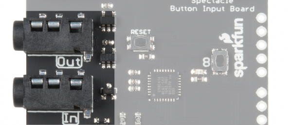
It has two 1/8" (3.5mm) jacks for connecting to other boards in a Spectacle system. Note that the Spectacle data jacks are directional: the one marked “In” should be plugged into the “upstream” board (i.e., closer to the Director Board than this one) and the one marked “Out” connects to the next downstream board.

Audio jacks

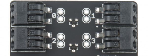
There are 8 “poke home” connectors on the Button Board. Each one can be connected to one (or more) buttons. To add a connection, simply push the stripped end of a wire into the hole on the connector. The connector will automatically grab on and hold the wire in place. If you need to remove the wire later, an small object (bobby pin, ballpoint pen, etc.) can be used to depress the release button, allowing the wire to be extracted without damage.

Poke home connectors

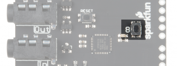
There is an input button on the button board itself which can be used to provide an input signal if no other buttons are available. It functions like any other normal button that might be attached. Be certain you’re pressing the button labeled ‘8’ and not the one labeled ‘Reset’! Pressing the reset button will reset your button board, probably causing your entire system to stop working properly until you reset your Director Board!

Onboard Button 8

Spectacle Motion Board

The Spectacle Motion Board makes it easy to add movement to your Spectacle projects. It can control up to 5 servo motors, either of standard or continuous rotation type.

Spectacle Motion Board

DEV-13993
14.95

tl;dr

  1. The USB Micro B port on the servo board is only for providing power to the attached motors.
  2. A single servo, or a couple of small servos, can be powered over the Spectacle control cable.
  3. Servo motors can be of the standard or continuous rotation type.

Meet the Spectacle Motion Board

Designed to make it easy to add simple motions to your Spectacle projects, the Spectacle Motion Board integrates with the rest of the Spectacle ecosystem to allow you to control motion effects relatively effortlessly.

It has two 1/8" (3.5mm) jacks for Spectacle control signals. Pay attention to the directionality of the jacks! The one labeled “In” should be plugged into a board that is closer to the Director Board than the Motion Board is, or into the director board itself.

Motion board IO jacks

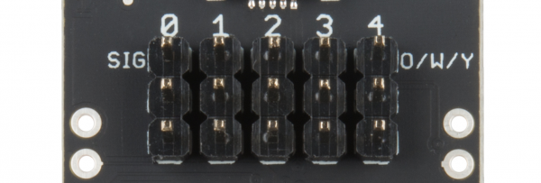
The Motion Board supports up to 5 servo motors. The servo motors can be either standard motion or continuous rotation servos. There’s a note on the board (“O/W/Y”) for the color which should be on the top row of the header: orange, white, or yellow. Most servo motors will have one wire which is one of these colors, and that wire should line up with this note.

Servo headers

The Motion Board has a Micro B USB connector to allow it to be directly powered by an external power supply. The relatively slender cables the Spectacle data travels over are not adequate for the large amount of current drawn by larger servo motors or by multiple motors.

Micro USB jack

The Configuration Utility

Spectacle Button Board

Button board action options

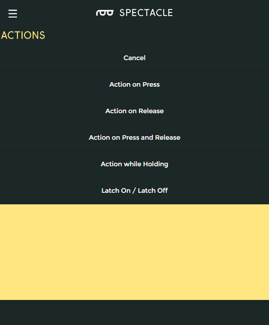
For the Button board, there are five options: three which produce a momentary pulse type output and two that produce a continuous switch type output.

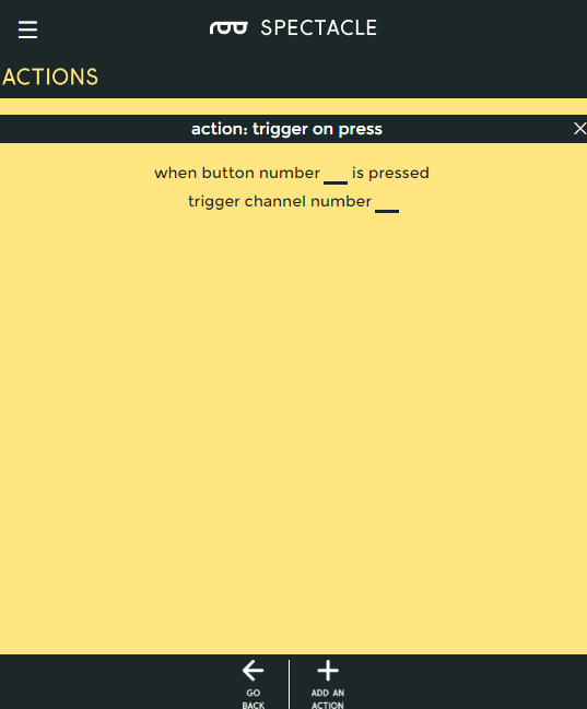
Action on press

Action on press options

Trigger an action when a button is first pressed, regardless of how long it is subsequently held down.

  • “When button number … is pressed” - This is the number of the button we wish to assign to this action. The button numbers are printed on the board, and run from 0 through 8.
  • “trigger channel number …” - A single, momentary pulse will be sent out on this channel. It is suitable for starting a sound, initiating a motion, or setting the color of a light strip, but not for continuous sound playback or for turning on a light strip effect, for instance.
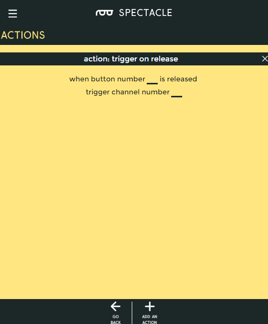
Action on release

action on release options

Trigger an action when a button is released, regardless of how long it has been held down prior to being released.

  • “When button number … is released” - This is the number of the button we wish to assign to this action. The button numbers are printed on the board, and run from 0 through 8.
  • “trigger channel number …” - A single, momentary pulse will be sent out on this channel. It is suitable for starting a sound, initiating a motion, or setting the color of a light strip, but not for continuous sound playback or for turning on a light strip effect, for instance.
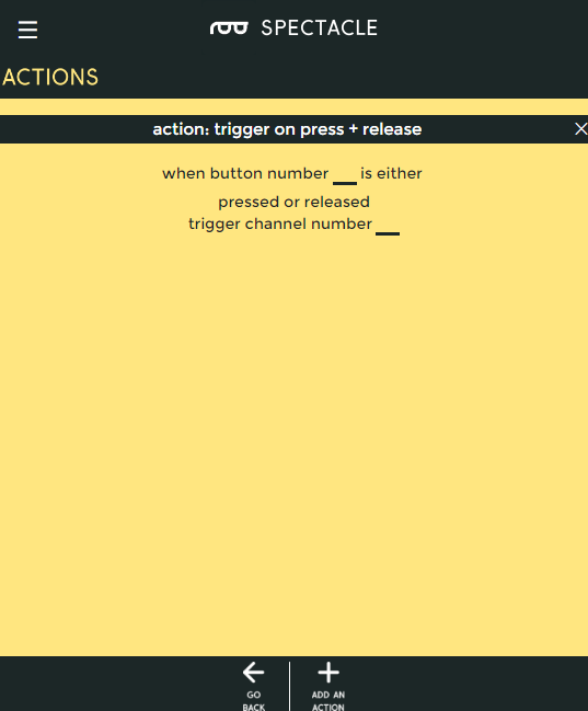
Action on press or release

Action on press or release options

Trigger an action when a button is pressed, then trigger the same action again when the button is released.

  • “When button number … is either pressed or released” - This is the number of the button we wish to assign to this action. The button numbers are printed on the board, and run from 0 through 8.
  • “trigger channel number …” - A single, momentary pulse will be sent out on this channel both at the time the button is pressed and at the time it is released. It is suitable for starting a sound, initiating a motion, or setting the color of a light strip, but not for continuous sound playback or for turning on a light strip effect, for instance.
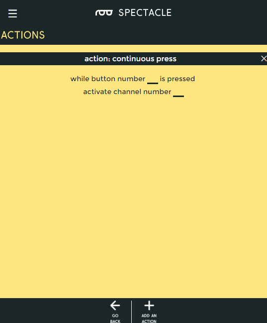
Action while holding

Action while holding options

Trigger an event as soon as a button is pressed, then continue to trigger that event as long as the button is held down.

  • “While button number … is pressed” - This is the number of the button we wish to assign to this action. The button numbers are printed on the board, and run from 0 through 8.
  • “activate channel number …” - A continuous will be sent out on this channel. It is suitable for triggering and repeating a sound, or for turning on and keeping on (at least, while the button is held) a lighting effect.
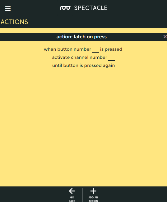
Latch On/Latch Off

Latch On/Off options

This action is like a latching power switch. One press turns the signal on, another later press turns the signal off.

  • “While button number … is pressed” - This is the number of the button we wish to assign to this action. The button numbers are printed on the board, and run from 0 through 8.
  • “activate channel number … until button is pressed again” - A continuous will be sent out on this channel. It is suitable for triggering and repeating a sound, or for turning on and keeping on a lighting effect.

Spectacle Motion Board

Motion Board Actions

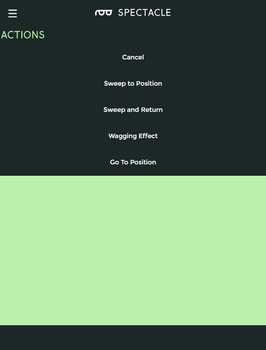
There are four actions associated with the motion board. Three of them are suitable for a momentary trigger and one for a continuous signal.

Sweep to Position

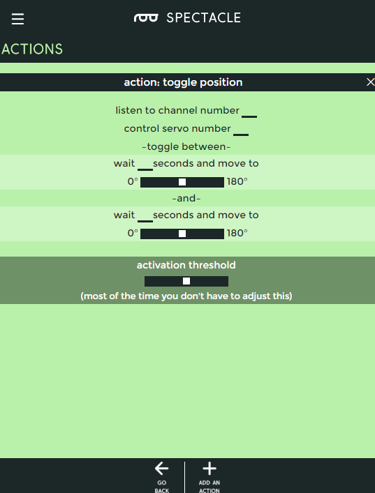
Toggle position action

This action moves the motor between two positions, one motion on each trigger event.

  • “listen to channel number …” - This is the channel which triggers the action.
  • “control servo number …” - The servo to be controlled, numbered from 0-4.
  • “wait … seconds and move to” - Delay before motion for the first position.
    • slider control - Choose the position for the first motion. The servo starts at 90° and can be rotated to 0° in one direction or to 180° in the other direction. This is equivalent to starting at 12 o'clock and turning to either 9 o'clock or 3 o'clock.
  • “wait … seconds and move to” - Delay before motion for the second position.
    • slider control - Choose the position for the second motion. The servo starts at 90° and can be rotated to 0° in one direction or to 180° in the other direction. This is equivalent to starting at 12 o'clock and turning to either 9 o'clock or 3 o'clock.
Sweep and Return

Sweep and return action options

This action waits for a moment, moves the servo to a position, then waits for a moment at the new position, then moves back to the first position.

  • “listen to channel number …” - Which channel controls this action.
  • “control servo number …” - The servo to be controlled, numbered from 0-4.
  • “wait … seconds and move to” - Delay before motion for the first position.
    • slider control - Choose the position for the first motion. The servo starts at 90° and can be rotated to 0° in one direction or to 180° in the other direction. This is equivalent to starting at 12 o'clock and turning to either 9 o'clock or 3 o'clock.
  • “wait … seconds and move to” - Delay before motion for the second position.
    • slider control - Choose the position for the second motion. The servo starts at 90° and can be rotated to 0° in one direction or to 180° in the other direction. This is equivalent to starting at 12 o'clock and turning to either 9 o'clock or 3 o'clock.
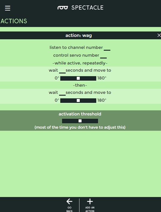
Wagging Effect

Wagging action

This action behaves much like sweep and return, but runs continuously until turned off by receipt of another signal pulse on the designated channel.

  • “listen to channel number …” - Which channel controls this action.
  • “control servo number …” - The servo to be controlled, numbered from 0-4.
  • “wait … seconds and move to” - Delay before motion for the first position.
    • slider control - Choose the position for the first motion. The servo starts at 90° and can be rotated to 0° in one direction or to 180° in the other direction. This is equivalent to starting at 12 o'clock and turning to either 9 o'clock or 3 o'clock.
  • “wait … seconds and move to” - Delay before motion for the second position.
    • slider control - Choose the position for the second motion. The servo starts at 90° and can be rotated to 0° in one direction or to 180° in the other direction. This is equivalent to starting at 12 o'clock and turning to either 9 o'clock or 3 o'clock.
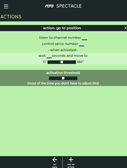
Go to Position

Go to position options

Move the servo motor from where ever it currently is to this new location after some delay.

  • “listen to channel number …” - Which channel controls this action.
  • “control servo number …” - The servo to be controlled, numbered from 0-4.
  • “wait … seconds and move to” - Delay before motion for the first position.
    • slider control - Choose the position for the first motion. The servo starts at 90° and can be rotated to 0° in one direction or to 180° in the other direction. This is equivalent to starting at 12 o'clock and turning to either 9 o'clock or 3 o'clock.

Example Project

Let’s use the Spectacle Motion Board Kit to make a project! We’re going to hook up the Button Board and the Motion Board to make a simple project where the motor moves from one position to another and then back when the button on the Button Board is pressed.

Connect the boards

All of the hardware you need for this tutorial is included in the kit.

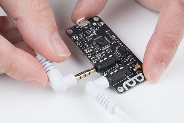
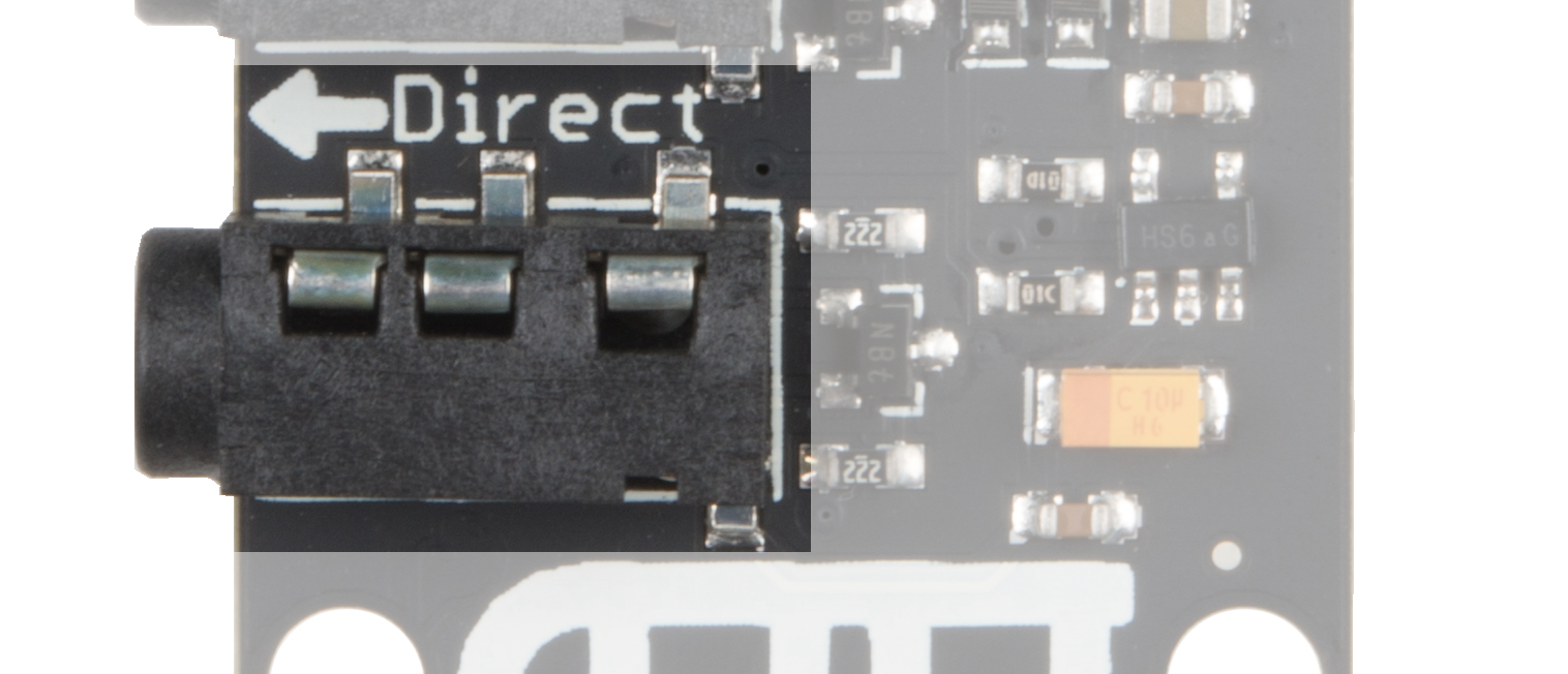
First, plug one end of one of the TRRS cables into the “Direct” jack on the Director Board.

The direct jack

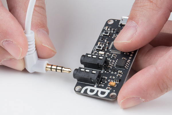
Next, take the other TRRS cable and plug it into the “Program” jack on the Director Board.

The program jack

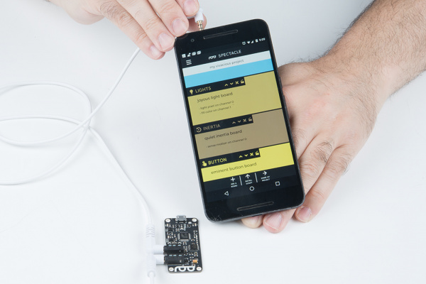
Take the other end of this cable and plug it into the audio jack of the phone, tablet, or computer that you’ll be using to program the system.

Into the phone jack

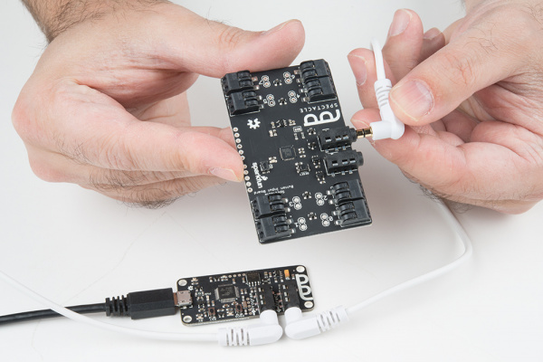
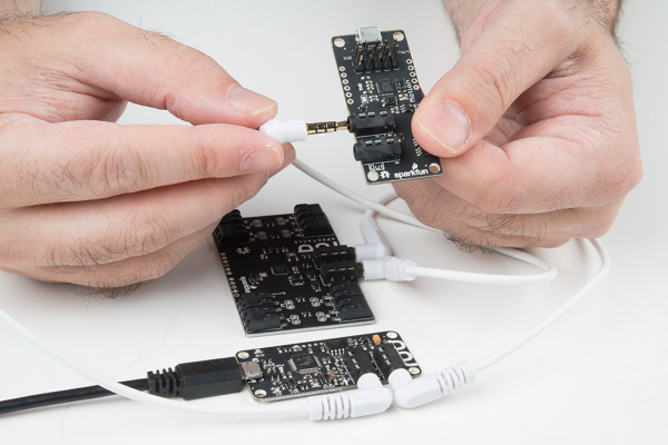
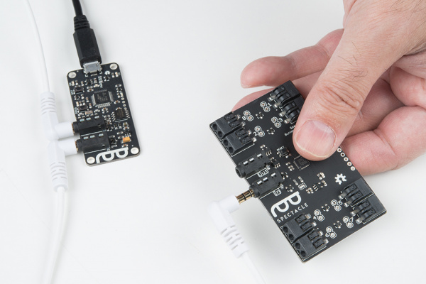
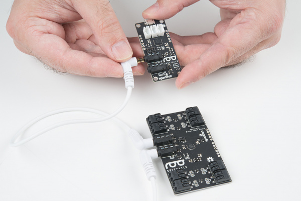
Then take the other end of that TRRS cable and plug it into the “In” jack on the Button Board.

Plugging into the in jack on the button board

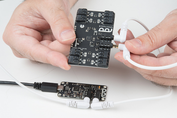
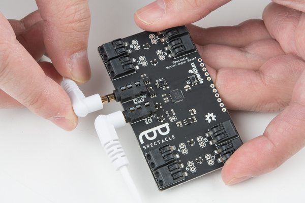
Grab another of the TRRS cables and plug it into the “Out” jack on the Button Board.

Connecting to the out jack on the button board

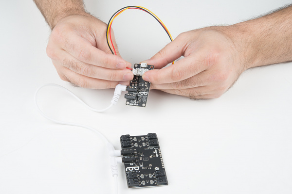
Plug the other end of that cable into the “In” jack on your Motion Board.

Plugging into the jack on motion board

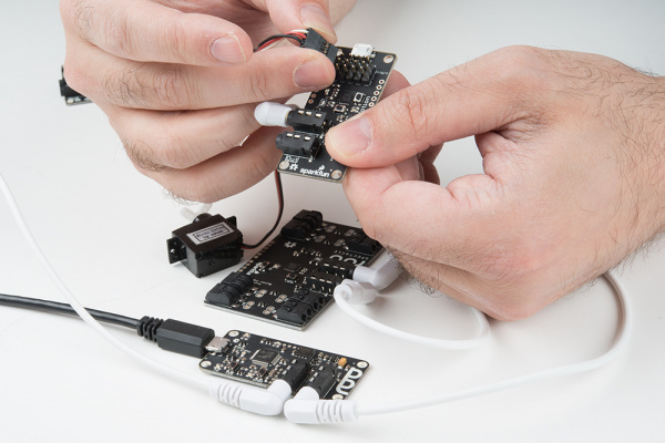
Now, plug the servo connector onto the Motion Board.

Connecting the servo to the motion board

Finally, plug the Micro B end of the power adapter into the Director board, and the other end into the wall. You should see one solid light and one blinking light on the Motion Board and the Button board. On the Director Board, you’ll see one solid light and one light which blinks one time, then pauses, then repeats. This shows that power is present and the boards are up and running.

Setting up the board configuration

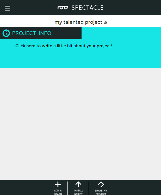
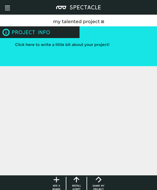
When you first open the Spectacle app webpage, this is what you’ll see. Your project name will differ from mine, as Spectacle assigns a random name to each project.

Blank project page

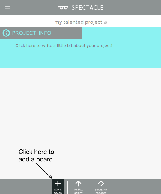
To continue, we must tell the project which boards we wish to use. Start by clicking the “Add a Board” button at the bottom of the page.

add a board button

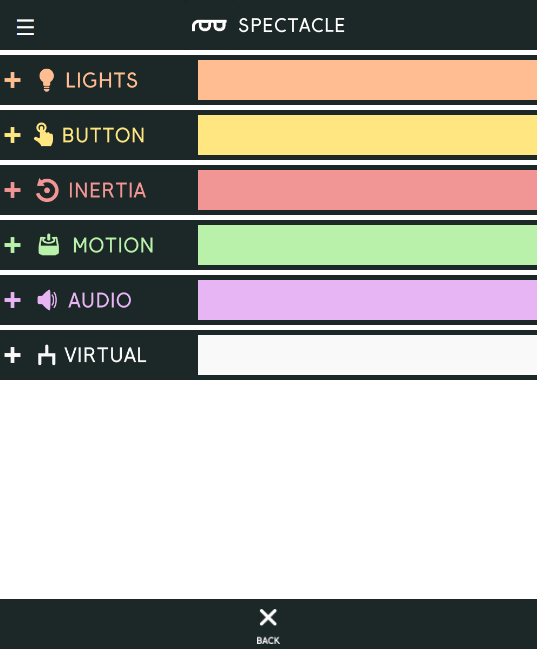
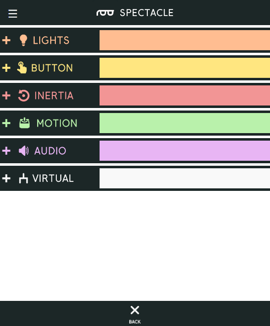
This will bring up a list of the available boards. We’re going to add our Button Board first of all, so click anywhere in the “Button” box to add it.

Now repeat these two steps, but add a Motion Board this time instead of another Button Board.

List of available boards

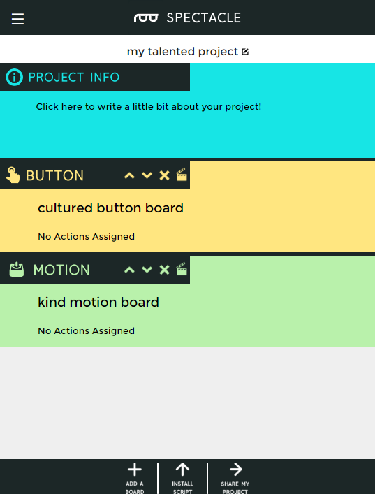
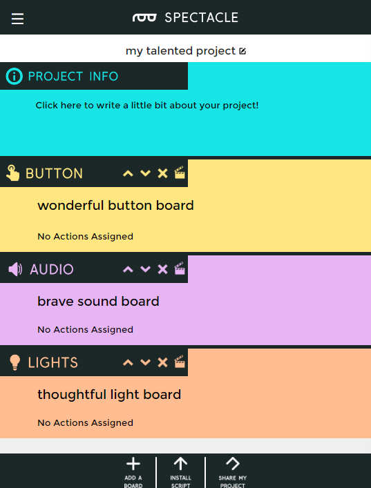
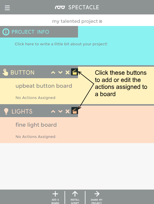
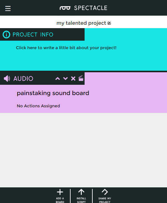
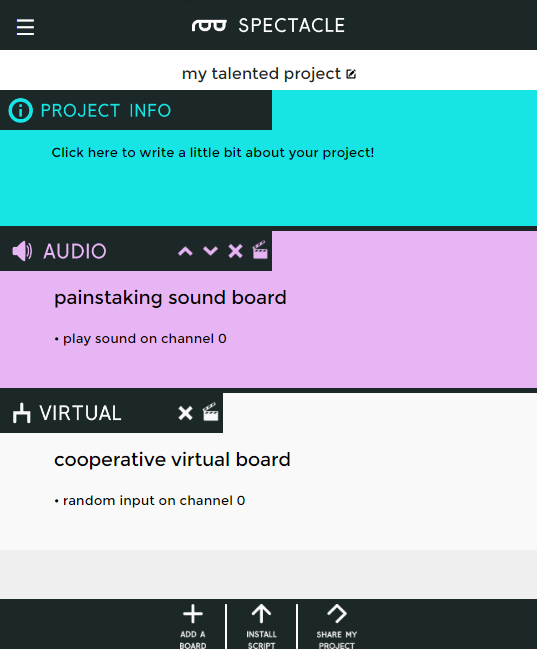
You’ll now have a screen that looks like this. To continue, we need to add some actions to the boards that tell the Spectacle system what we want the boards to do.

Boards added to project

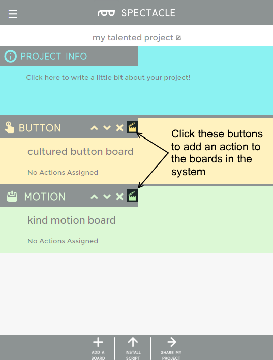
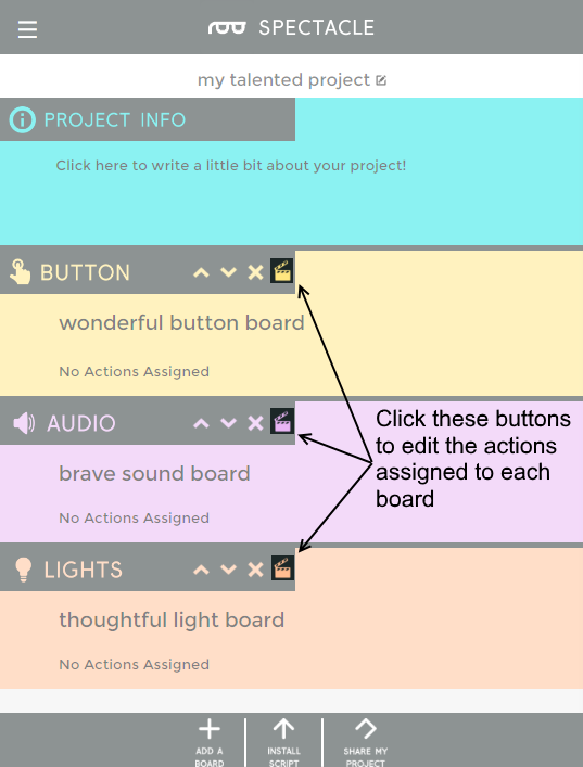
To add actions, click on the clapboard icons as highlighted above. We’re going to do the Button Board first.

Add action buttons highlighted

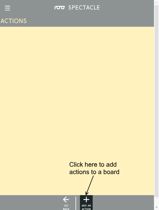
You’ll then see a list of actions assigned to the board which will, of course, be empty. To add an action, click the “Add an Action” button at the bottom of the page as highlighted below.

blank action page, add button highlighted

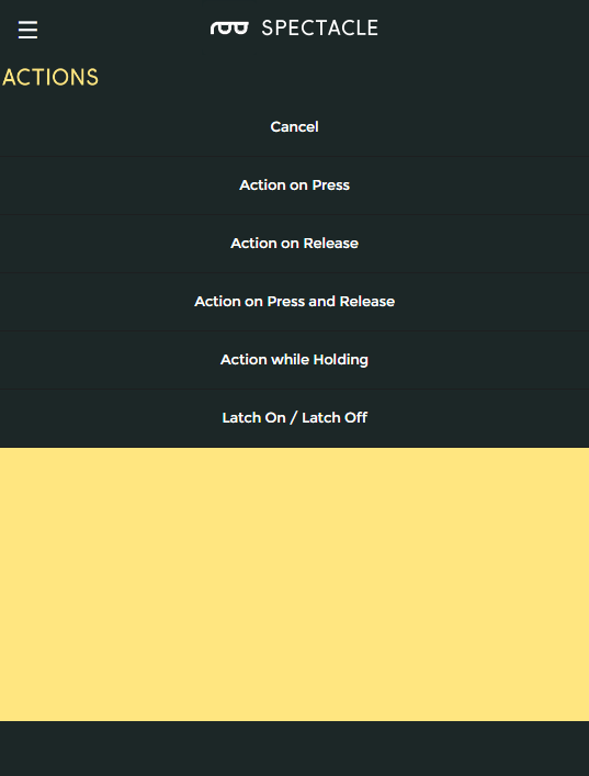
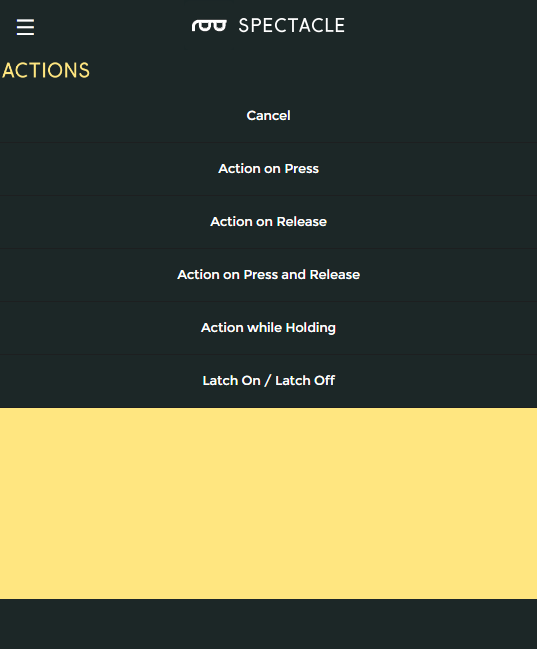
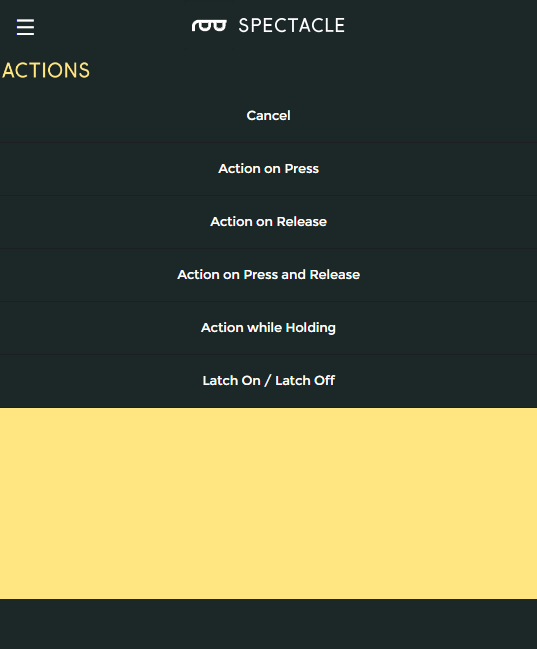
Here we see the available actions for the Button Board. We’re going to select the first one, “Action on Press”. Click that entry to select it.

actions for button board

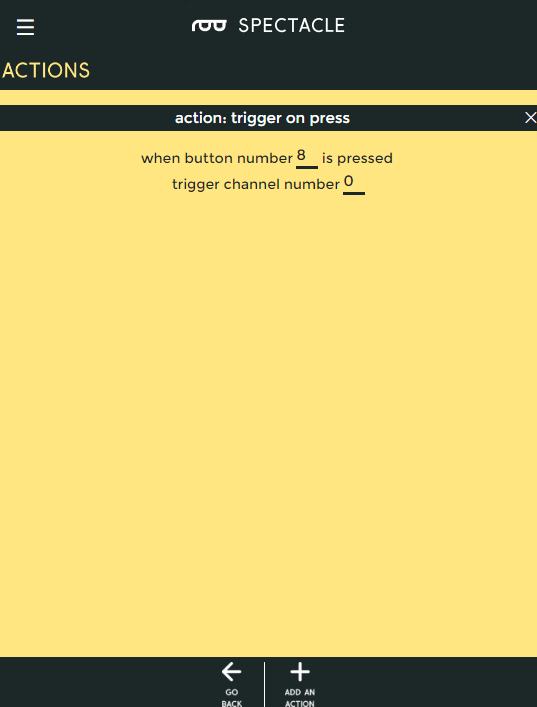
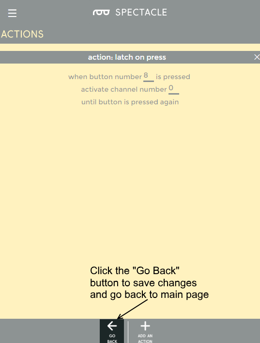
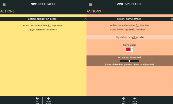
This is the “Trigger on Press” action options screen. I’ve already entered the data in the fields: button 8 to channel 0. Button 8 is the Button Board’s built-in button. Now click the “Go Back” button at the bottom of the page to go back to the main page, so we can add an action to the Motion Board.

trigger on press action options

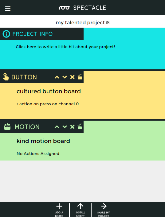
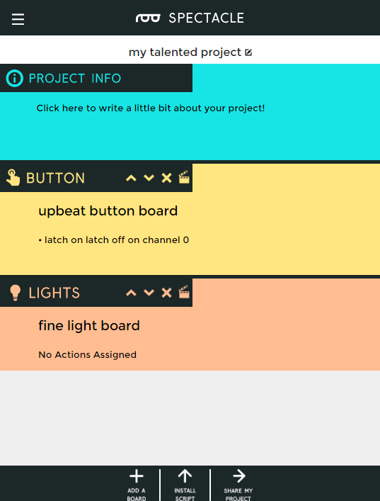
Back at the main page, you can see that the action we just added to the Button Board shows up listed under that board in the boards list. Click on the Motion Board clapboard icon to bring up the action list for it.

Main page, with an action

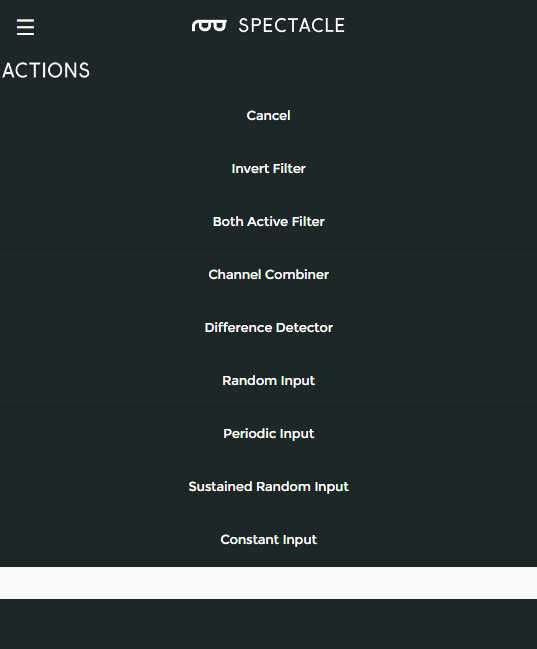
Here is the list of possible actions for the Motion Board. We’re going to add a “Sweep and Return” action.

actions for the motion board

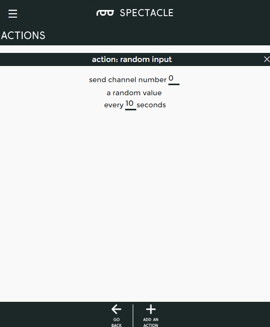
I’ve put the settings we want into the “Sweep and Return” page settings. Click “Go Back” to save the changes and return to the main board list.

Settings for the sweep and return action

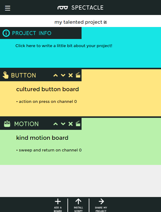
Congratulations! You’ve finished the configuration step of the process. Now it’s time to move on to loading the project onto your Director Board.

Finished project

Uploading

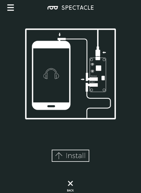
Now that you’ve created your Spectacle program it’s time to upload it to the Director Board. If you followed the instructions above, your uploading device is connected to the board and ready to go, so all you need to do is touch the “Install Script” button at the bottom of the page. That will bring up the page seen below.

Upload page

Make sure the volume on your device is turned all the way up, and that no other audio source (music, video, etc) is playing in the background. Then press and hold the “RST” button on the Director Board, press and hold the “PROG” button, then release the “RST” button.

This will put the Director Board into program mode. You’ll see the light on the board blink three times, pause, then repeat. This is your visual indicator that the board is in program mode. Once you’ve established that the board is in program mode, you can begin programming by touching the “Install” button on the Spectacle app screen. The button will gray out during the programming process, which should only last for a few seconds. Once programming is done, you’ll see the light on the Director Board blink 10 times, pause, then repeat. That’s your cue that the program was uploaded successfully.

Press the “RST” button again to reset the system and begin the program!

If you have any troubles, visit the troubleshooting page for help resolving your issues.

Further reading

For general Spectacle information, please check out the user guide:

New!

Spectacle User's Guide

May 4, 2017

The Spectacle system is designed to help those without electronics or programming experience integrate electronics into projects.

For more Spectacle fun, check out the additional tutorials below:

New!

Spectacle Audio Board Hookup Guide

All the information you need to use the Spectacle Audio Board in one place.
New!

Spectacle User's Guide

The Spectacle system is designed to help those without electronics or programming experience integrate electronics into projects.
New!

Spectacle Light Kit Hookup Guide

All the information you need to use the Spectacle Light Kit in one place.
New!

Spectacle Inertia Board Hookup Guide

Everything you need to know about using the Spectacle Inertia Board in one place.
New!

Spectacle Light and Sound Kit Hookup Guide

All the information you need to use the Spectacle Light and Sound Kit in one place.
New!

Spectacle Button Board Hookup Guide

All the information you need to use the Spectacle Button Board in one place.

learn.sparkfun.com |CC BY-SA 3.0 | SparkFun Electronics | Niwot, Colorado


Spectacle Example: Super Mario Bros. Diorama

$
0
0

Spectacle Example: Super Mario Bros. Diorama a learn.sparkfun.com tutorial

Available online at: http://sfe.io/t638

Introduction

Spectacle is designed to make complicated electronics projects simple, so you can focus on what you do best: making cool things!

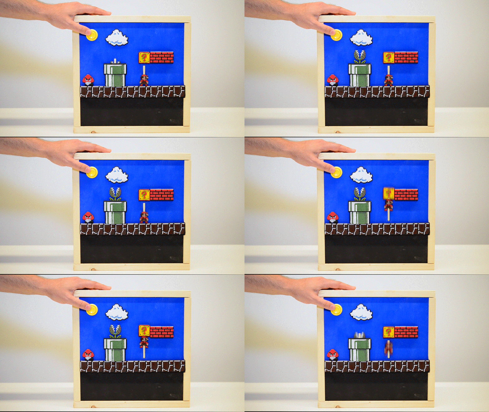
In this tutorial, we’ll show you how to make an animated diorama (with sound effects!) using Spectacle.

Gif of mario box in action

Techniques of note

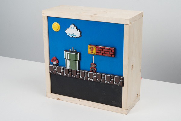
We created the tiles for the diorama using this project from Thingiverse. We 3D printed the tiles, then painted them accordingly.

Picture of the project

The layout was designed in Inkscape, then etched into the wood with a laser cutter. The laser cutter was also used to cut out the slots that the moving pieces ride up and down in. Of course, this step is optional. The tiles could easily be placed by hand, and the cuts could be made with a hobby knife or similar woodworking tool.

Prior Reading

This tutorial assumes a basic familiarity with the Spectacle system. If you haven’t yet, read the following tutorials for all the basic information you’ll need to know to get this project going:

New!

Spectacle User's Guide

The Spectacle system is designed to help those without electronics or programming experience integrate electronics into projects.
New!

Spectacle Audio Board Hookup Guide

All the information you need to use the Spectacle Audio Board in one place.
New!

Spectacle Button Board Hookup Guide

All the information you need to use the Spectacle Button Board in one place.
New!

Spectacle Motion Board Hookup Guide

All the information you need to use the Spectacle Motion Kit in one place.

Animating the Diorama

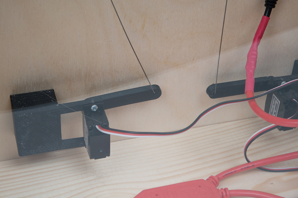
To animate the diorama, we 3D printed a longer arm for the servo motor. The length of the arm must be approximately equal to the linear distance the moving component is expected to cover.

We then attached a piece of 0.020" (0.5mm) music wire to the end of the arm. The wire must be affixed in such a way that it can rotate freely as the arm moves. We passed it through a hole in the arm and bent it to a shape that will be retained by the hole.

Close up of the longer arm with wire in place

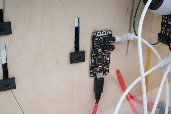
The other end of the wire was affixed to the slide mechanism to which the tiles were glued. In that case, a small loop is printed on the back of the slide mechanism and the wire is again bent into a shape that will be retained by that loop. The wire is rigid enough to push the tiles into a new position, but flexible enough to bend when the stop is hit.

Shuttle back

Adding Sound

We elected to keep the sound simple for this project, using the delaying mechanism of the Audio Board to trigger the sounds at the appropriate time rather than trying to trigger the sound by having Mario hit another switch.

Finding sound effects is left as an exercise for the reader, to prevent possible copyright or trademark issues. A quick web search will turn up sound effects for most projects, however.

Spectacle Project

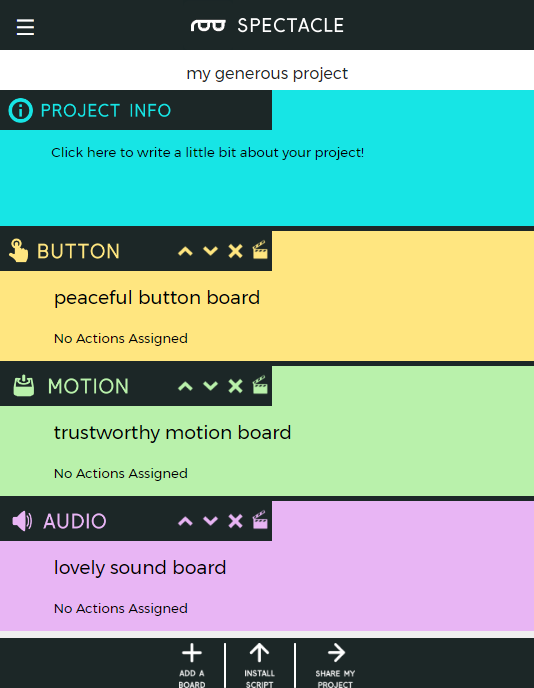
The Spectacle project for this setup is very simple. It consists of a Button Board, a Motion Board, and an Audio Board. We’ll just give you the pages of the project here, rather than walk you step-by-step through making a Spectacle project. Below, find the main page of the app, with all the boards in place. Remember that the order the boards are connected in must match the order they appear in the app list in.

Main Window showing boards

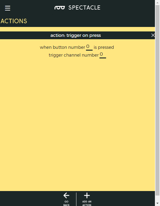
Here are the settings for the Button Board. Note that, although we’re triggering four separate actions, we only need to have a signal on one channel.

Button Board settings

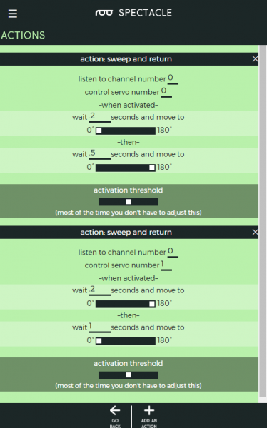
Here we see the Motion Board settings. You’ll note that there’s a slight delay between receipt of the triggering signal and activation of the first motion. That accounts for the brief delay between triggering the Sound Board and the sound actually playing. The sliders are opposite because the position of the motors is mirrored on the inside of the project.

Motion Board settings

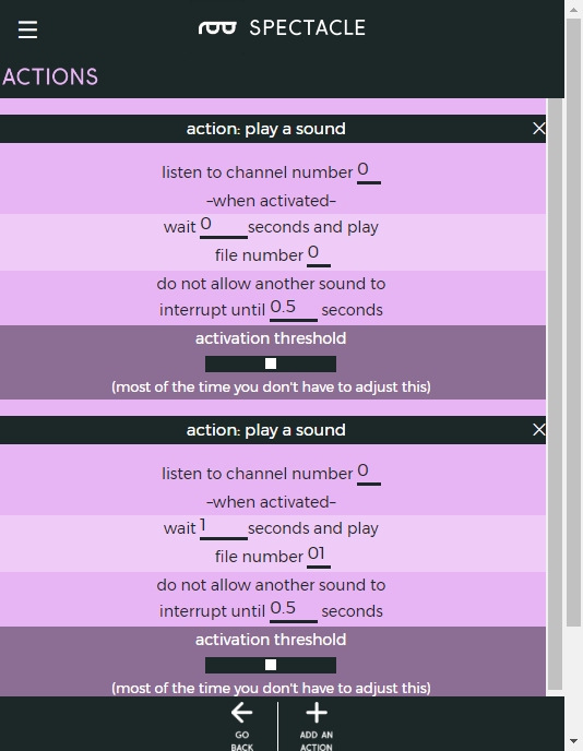
Finally, here are the settings for the two sound events on the Sound Board. By layering them like this, we create the illusion of triggering the second sound when Mario hits the block without having to put a switch on that block.

Audio Board settings

Note that these are timing values for my system and you’ll probably have to change them if you do your own. I figured these out by playing around with it a bit.

Further reading

For general Spectacle information, please check out the user guide:

New!

Spectacle User's Guide

May 4, 2017

The Spectacle system is designed to help those without electronics or programming experience integrate electronics into projects.

For more Spectacle fun, check out the additional tutorials below:

New!

Spectacle Audio Board Hookup Guide

All the information you need to use the Spectacle Audio Board in one place.
New!

Spectacle User's Guide

The Spectacle system is designed to help those without electronics or programming experience integrate electronics into projects.
New!

Spectacle Light Kit Hookup Guide

All the information you need to use the Spectacle Light Kit in one place.
New!

Spectacle Light Board Hookup Guide

All the information you need to use the Spectacle Light Board in one place.
New!

Spectacle Inertia Board Hookup Guide

Everything you need to know about using the Spectacle Inertia Board in one place.
New!

Spectacle Motion Kit Hookup Guide

All the information you need to use the Spectacle Motion Kit in one place.
New!

Spectacle Button Board Hookup Guide

All the information you need to use the Spectacle Button Board in one place.
New!

Spectacle Light and Sound Kit Hookup Guide

All the information you need to use the Spectacle Light and Sound Kit in one place.

learn.sparkfun.com |CC BY-SA 3.0 | SparkFun Electronics | Niwot, Colorado

Spectacle Light and Sound Kit Hookup Guide

$
0
0

Spectacle Light and Sound Kit Hookup Guide a learn.sparkfun.com tutorial

Available online at: http://sfe.io/t621

Introduction

The Spectacle Light and Sound Kit allows you to add button-activated sound and light effects to your projects with ease.

Spectacle Light and Sound Kit

KIT-14173
149.95

Suggested Reading

Before proceeding, you should read through the Spectacle User’s Guide. It will give you the basics you’ll need to know about how Spectacle works to follow the rest of this tutorial.

Spectacle Audio Board

The Spectacle Audio Board allows you to add sound to your Spectacle projects. It accepts a microSD card with sounds in .ogg format (more on this later), and has a 1/8" (3.5mm) audio jack to connect to external amplifiers.

Spectacle Audio Board

DEV-14034
14.95

tl;dr (essentials)

  1. Audio files for Spectacle should be formatted as .ogg files.
  2. Audio files should have names 00.ogg, 01.ogg, 02.ogg, etc.
  3. The audio jack on the Audio Board produces output suitable for amplification only. It is not suited to headphones or unpowered speakers.

Meet the Spectacle Audio Board

Designed to be a low-cost and easy to use method of adding sound to projects, the Spectacle Audio Board integrates with the rest of the Spectacle ecosystem to provide sound effects on demand.

It has three 1/8" (3.5mm) jacks: two for Spectacle control signals and one for the audio output. Be certain you are plugging cables into the right jacks! Plugging an audio device into one of the Spectacle jacks could cause damage to the audio device. Note that the Spectacle data jacks are directional: the one marked “In” should be plugged into the “upstream” board (i.e., closer to the Director Board than this one) and the one marked “Out” connects to the next downstream board. The “Out” jack is not for audio signals.

Spectacle IO jacks

The audio output is designed for amplified devices only. This means that any attempt to use the Spectacle Audio Board with headphones or unamplified speakers will fail to produce audible output. SparkFun sells a small, amplified, rechargeable speaker which is specifically intended for use with the Spectacle Audio Board.

Audio jack

The Spectacle Audio Board uses a microSD card to store the audio files to be played. The files should be stored as .ogg Vorbis encoded files. This free audio file format can be played and created on any type of computer. Later in the tutorial we’ll show you how to convert from MP3, WAV, or other file formats to the .ogg format.

SD Card Slot

The files must be named by number, which is how they will be referred to from within the configuration application. Filename examples are 00.ogg, 01.ogg, 02.ogg, and so forth.

Spectacle Button Board

The Spectacle Button Board allows you to add input from buttons or switches to your Spectacle projects. It has a total of 9 signal inputs, eight of which can come from external buttons and one button directly on the board.

Spectacle Button Board

DEV-14044
14.95

tl;dr

  1. Buttons or switches can be connected to the board by pushing wires into the “poke home” type connectors on the board.
  2. Up to nine signals are available.
  3. Button signals can be either momentary or continuous.

Meet the Spectacle Button Board

Designed to bring simple signals from the world into your Spectacle projects, the Spectacle Button Board provides input for any of your Spectacle projects.

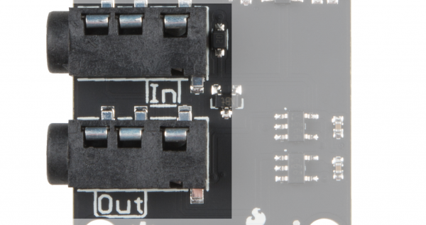
It has two 1/8" (3.5mm) jacks for connecting to other boards in a Spectacle system. Note that the Spectacle data jacks are directional: the one marked “In” should be plugged into the “upstream” board (i.e., closer to the Director Board than this one) and the one marked “Out” connects to the next downstream board.

Audio jacks

There are 8 “poke home” connectors on the Button Board. Each one can be connected to one (or more) buttons. To add a connection, simply push the stripped end of a wire into the hole on the connector. The connector will automatically grab on and hold the wire in place. If you need to remove the wire later, an small object (bobby pin, ballpoint pen, etc.) can be used to depress the release button, allowing the wire to be extracted without damage.

Poke home connectors

There is an input button on the button board itself which can be used to provide an input signal if no other buttons are available. It functions like any other normal button that might be attached. Be certain you’re pressing the button labeled ‘8’ and not the one labeled ‘Reset’! Pressing the reset button will reset your button board, probably causing your entire system to stop working properly until you reset your Director Board!

Onboard Button 8

Spectacle Light Board

The Spectacle Light Board allows you to add some fairly complex lighting effects to your Spectacle projects. It has connections for up to three strands of addressable LEDs and a connector for external power.

Spectacle Light Board

DEV-14052
14.95

tl;dr

  1. If more than approximately 10 pixels will be on at once, we recommend powering the Light Board through the onboard micro-B USB port.
  2. For smaller numbers of pixels, it is possible to power them directly over the Spectacle control cable.
  3. Most of the LED effects want a continuous type signal, such as the Button board “Latch On/Latch Off” function.
  4. Only WS2812 (NeoPixel) type addressable LED strips will work with the Spectacle Light Board.

Meet the Spectacle Light Board

Designed to make it easy to add relatively complex lighting effects to your Spectacle projects, the Spectacle Light Board integrates with the rest of the Spectacle ecosystem to allow you to control lighting effects relatively effortlessly.

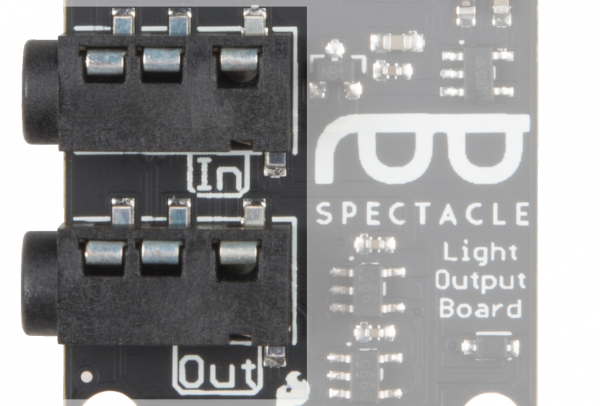
It has two 1/8" (3.5mm) jacks for Spectacle control signals. Pay attention to the directionality of the jacks! The one labeled “In” should be plugged into a board that is closer to the Director Board than the Light Board is, or into the Director Board itself.

Signal jacks

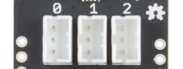
The Light Board supports up to three strands of addressable LEDs. Each strand can have up to 60 individual pixels. Not all types of addressable LEDs are compatible with the Spectacle Light Board. If you have questions about whether or not a particular type of LED strip is compatible with the Light Board, contact SparkFun technical support.

LED Strand Connectors

The Light Board has a Micro B USB connector to allow it to be directly powered by an external power supply. The relatively slender cables the Spectacle data travels over are not adequate for the large amount of current drawn by more than a few pixels.

USB Power Jack

The Configuration Utility

Spectacle Audio Board

Sound interface

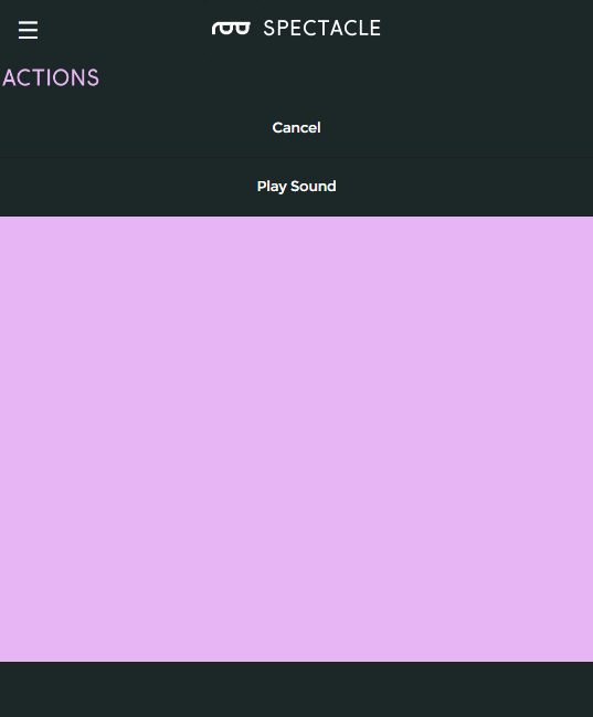
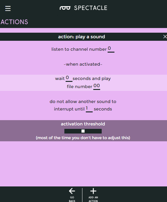
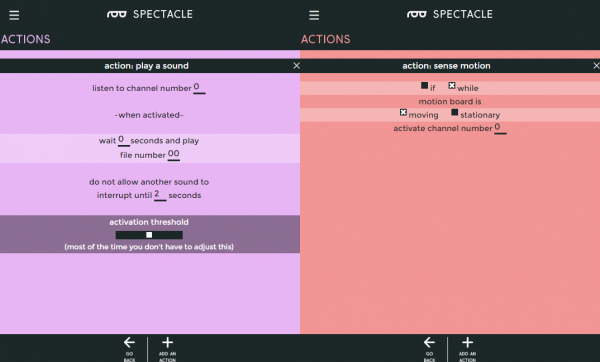
The Spectacle Audio Board only supports one action: Play Sound. As you can see above, there are a number of settings associated with this action.

  • “listen to channel number __” - This is the channel number which triggers the audio to start playing. As long as this channel’s value is above the threshold level (see below), the sound will repeat playing at a rate determined by the two time intervals specified lower down.
  • “wait __ seconds and play” - This is the first delay in the system. You can sequence events however you see fit by delaying when a sound plays.
  • “file number __” - This is where you tell the board which file to play. Remember, when copying the audio files to the microSD card, they should be named as 00.ogg, 01.ogg, 02.ogg, etc. The number in this field corresponds to the number in the name of the audio file. If there is no audio file with the corresponding number, no sound will play.
  • “do not allow another sound to interrupt until __ seconds” - The number in this field should correspond to the length of the audio file. If this value is less than the length of the sound file, another trigger sent to the audio board will interrupt the sound before it finishes. If it is longer than the sound, there will be a period of silence after playback before another playback can be initiated.
  • “activation threshold” - As it says in the app, most of the time you don’t need to adjust this. Adjusting the slider can set the angle at which the Spectacle Accelerometer Board triggers a sound, or the frequency with which a Random Trigger Virtual Board causes a sound to play.

Spectacle Button Board

Button board action options

For the Button board, there are five options: three which produce a momentary pulse type output and two that produce a continuous switch type output.

Action on press

Action on press options

Trigger an action when a button is first pressed, regardless of how long it is subsequently held down.

  • “When button number __ is pressed” - This is the number of the button we wish to assign to this action. The button numbers are printed on the board, and run from 0 through 8.
  • “trigger channel number __” - A single, momentary pulse will be sent out on this channel. It is suitable for starting a sound, initiating a motion, or setting the color of a light strip. This feature is not intended for continuous sound playback or for turning on a light strip effect.
Action on release

action on release options

Trigger an action when a button is released, regardless of how long it has been held down prior to being released.

  • “When button number __ is released” - This is the number of the button we wish to assign to this action. The button numbers are printed on the board, and run from 0 through 8.
  • “trigger channel number __” - A single, momentary pulse will be sent out on this channel. It is suitable for starting a sound, initiating a motion, or setting the color of a light strip, but not for continuous sound playback or for turning on a light strip effect, for instance.
Action on press or release

Action on press or release options

Trigger an action when a button is pressed, then trigger the same action again when the button is released.

  • “When button number __ is either pressed or released” - This is the number of the button we wish to assign to this action. The button numbers are printed on the board, and run from 0 through 8.
  • “trigger channel number __” - A single, momentary pulse will be sent out on this channel both at the time the button is pressed and at the time it is released. It is suitable for starting a sound, initiating a motion, or setting the color of a light strip, but not for continuous sound playback or for turning on a light strip effect, for instance.
Action while holding

Action while holding options

Trigger an event as soon as a button is pressed, then continue to trigger that event as long as the button is held down.

  • “While button number __ is pressed” - This is the number of the button we wish to assign to this action. The button numbers are printed on the board, and run from 0 through 8.
  • “activate channel number __” - A continuous will be sent out on this channel. It is suitable for triggering and repeating a sound, or for turning on and keeping on (at least, while the button is held) a lighting effect.
Latch On/Latch Off

Latch On/Off options

This action is like a latching power switch. One press turns the signal on, another later press turns the signal off.

  • “While button number __ is pressed” - This is the number of the button we wish to assign to this action. The button numbers are printed on the board, and run from 0 through 8.
  • “activate channel number __ until button is pressed again” - A continuous will be sent out on this channel. It is suitable for triggering and repeating a sound, or for turning on and keeping on a lighting effect.

Spectacle Light Board

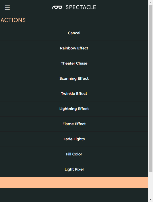
Action list for light board

The Light Board supports 9 different actions. Most of them want a continuous-type signal input, although a couple of them can be used with momentary input signals. We’ll cover the difference under each action. Each action will have a field for the number of pixels the lightstrip that action is being applied to has, and we won’t mention it again.

Rainbow Effect

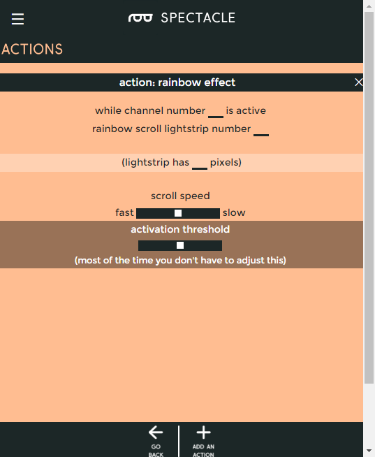
Rainbow effect settings

The rainbow effect displays a rainbow of colors across the strip, changing the color of each pixel indvidually to make it appear as though the rainbow is scrolling along the lightstrip.

  • “While channel number __ is active” - The rainbow effect persists only while the channel is active, so a continuous input signal is needed.
  • “rainbow scroll lightstrip number __” - Select which lightstrip you wish the rainbow effect to operate on. To have the same effect on multiple lightstrips, you must create multiple actions.
  • scroll speed slider - controls how fast the pattern moves as it scrolls past.
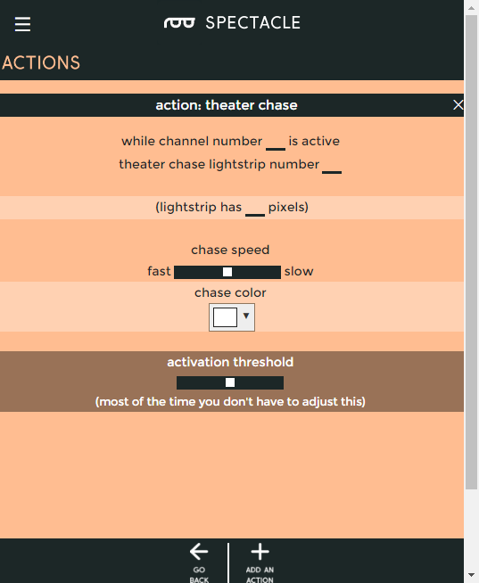
Theater chase

Theater chase settings

Theater chase mode behaves like a marquee light border. The lights will march along making it appear as though the lightstrip is moving in steps.

  • “While channel number __ is active” - The theater chase effect persists only while the channel is active, so a continuous input signal is needed.
  • “theater chase lightstrip number __” - Select which lightstrip you wish the theater chase effect to operate on. To have the same effect on multiple lightstrips, you must create multiple actions.
  • chase speed slider - controls how fast the pattern moves as it scrolls past.
  • color picker input - allows you to select the color of the lights.
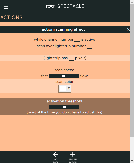
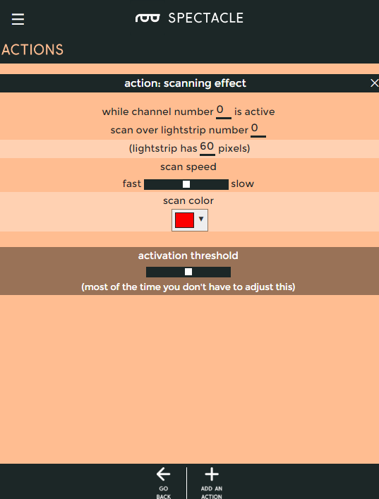
Scanning effect

Scanning effect settings

Scanning mode sees a small group of lights bouncing back and forth along the length of the lightstrip, reminiscent of Cylons from Battlestar Galactica.

  • “While channel number __ is active” - The scanning effect persists only while the channel is active, so a continuous input signal is needed.
  • “scan lightstrip number __” - Select which lightstrip you wish the scanning effect to operate on. To have the same effect on multiple lightstrips, you must create multiple actions.
  • scan speed slider - controls how fast the pattern moves as it scrolls past.
  • color picker input - allows you to select the color of the lights.
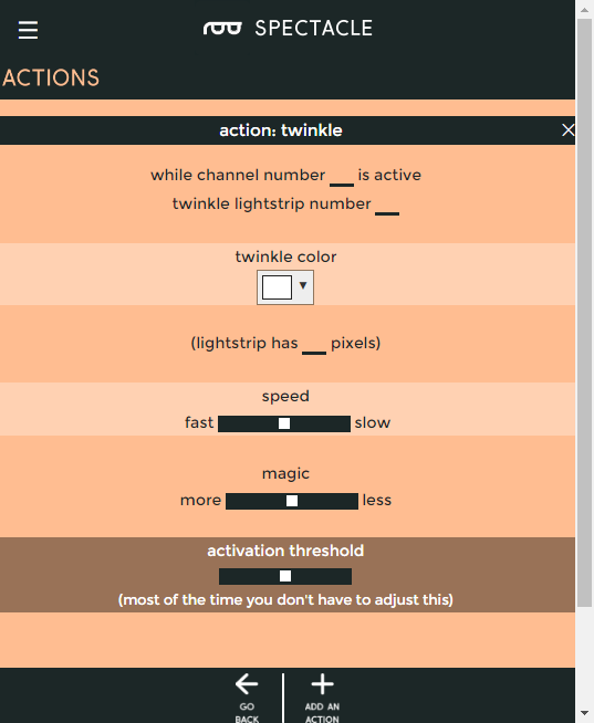
Twinkle effect

Twinkle effect settings

Causes individual lights on the selected strip to perform a twinkling action.

  • “While channel number __ is active” - The twinkle effect persists only while the channel is active, so a continuous input signal is needed.
  • “twinkle lightstrip number __” - Select which lightstrip you wish the twinkle effect to operate on. To have the same effect on multiple lightstrips, you must create multiple actions.
  • color picker input - allows you to select the color of the lights.
  • speed slider - controls how fast the twinkles are moves as it scrolls past.
  • magic slider - controls how magical the twinkles are. Play with it!
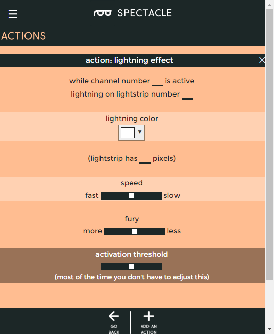
Lightning effect

Lightning effect settings

Causes the entire strip to strobe in a manner that looks a lot like a lightning flash.

  • “While channel number __ is active” - The lightning effect persists only while the channel is active, so a continuous input signal is needed.
  • “lightning on lightstrip number __” - Select which lightstrip you wish the lightning effect to operate on. To have the same effect on multiple lightstrips, you must create multiple actions.
  • color picker input - allows you to select the color of the lights.
  • speed slider - controls how often the lightning strike occur moves as it scrolls past.
  • fury slider - controls how furious the lightning is. Play with it!
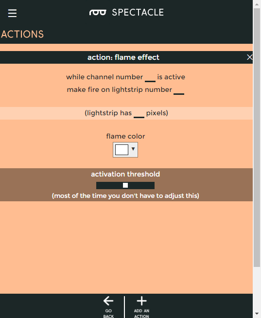
Flame effect

Flame effect settings

Causes the entire strip to crackle like a fire.

  • “While channel number __ is active” - The flame effect persists only while the channel is active, so a continuous input signal is needed.
  • “make fire on lightstrip number __” - Select which lightstrip you wish the flame effect to operate on. To have the same effect on multiple lightstrips, you must create multiple actions.
  • color picker input - allows you to select the color of the lights. Experiment with different colors!
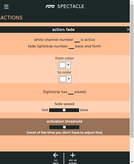
Fade effect

Fade effect settings

The lightstrip will change from one color to another over time, then back to the first.

  • “While channel number __ is active” - The fade effect persists only while the channel is active, so a continuous input signal is needed.
  • “fade lightstrip number __ back and forth” - Select which lightstrip you wish the fade effect to operate on. To have the same effect on multiple lightstrips, you must create multiple actions.
  • “from color” color picker - This is the initial color that the lightstrip will power up with.
  • “to color” color picker - The other color, which the strip fades to and from periodically.
  • “fade speed” slider - Controls how fast the fading action occurs.
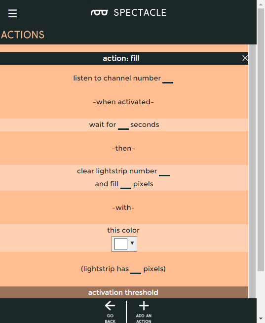
Fill

Fill settings

Fills some number of lights on the light strip with a single color. Blanks the other lights to off.

  • “listen to channel number __” - A momentary signal on this channel is all that is needed to trigger a fill operation, and the fill will persist until another effect starts.
  • “wait for __ seconds” - This delay allows for sequencing effects. Most often you’ll probably set it to 0.
  • “clear lightstrip number __” - Select the lightstrip to operate upon.
  • “and fill __ pixels” - The number of pixels, from closest to the Light board out, to turn on.
Light pixel

Pixel settings

Turns on one light and blanks the rest of the lights to off.

  • “listen to channel number __” - A momentary signal on this channel is all that is needed to trigger a light pixel operation, and the lit pixel will persist until another effect starts.
  • “wait for __ seconds” - This delay allows for sequencing effects. Most often you’ll probably set it to 0.
  • “clear lightstrip number __” - Select the lightstrip to operate upon.
  • “and light pixel number __ ” - The number of the pixel, from closest to the Light board out, to turn on.

Converting Sounds to OGG Vorbis Format

The files used by the Spectacle Audio Board must be in OGG Vorbis format. This free, lossy codec has a higher compression ratio than MP3, and, more importantly, can be used without paying a licensing fee to any third part organization.

Download and Install Audacity

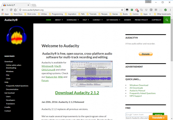
We’ll be using the free, open source program “Audacity” to convert from whatever your file’s current format is to OGG Vorbis.

Audacity website

Audacity is available across all three major operating systems, so you shouldn’t have any trouble getting it installed.

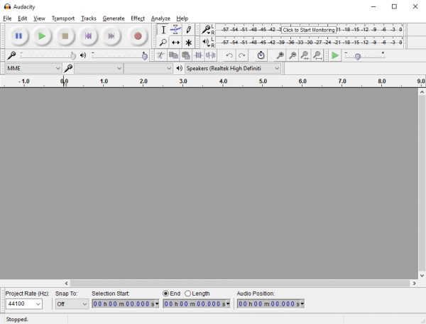
When you start Audacity, you’ll see this screen, or one very like it. While at first blush it seems extremely complex, none of this crap is important to us, so don’t panic.

Audacity main screen

Load a file

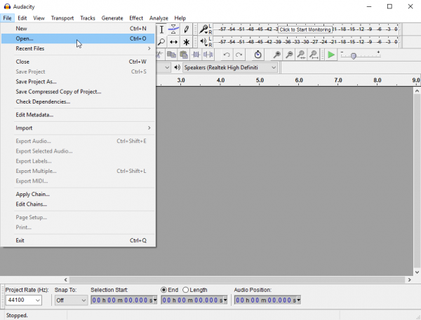
Like most programs, “loading a file” just means selecting “Open” from the File menu and choosing which file you wish to convert. Audacity is capable of editing most types of audio files: WAV, AIFF, FLAC, MP3, and others.

Audacity file menu

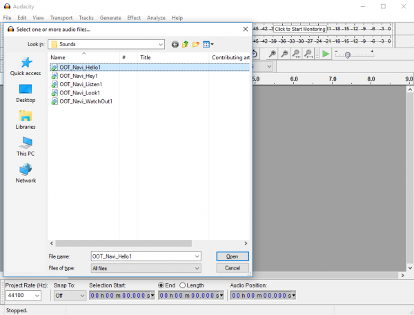
By default, Audacity shows all files, not just compatible audio files, when you bring up the open dialog. There’s a dropdown menu that allows you to change that so it shows only compatible audio files along the bottom edge of the window.

Audacity open file dialog

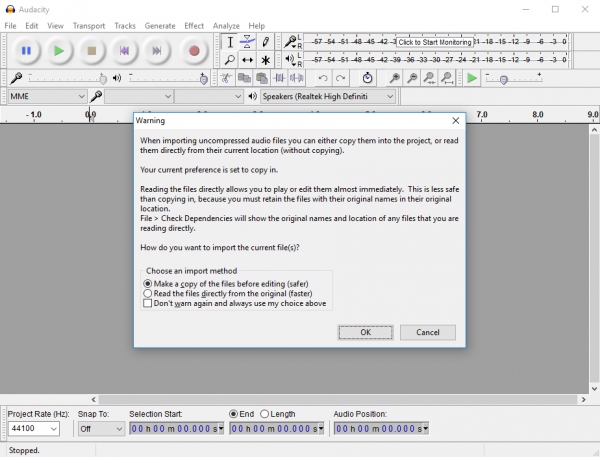
Once you select which file you wish to edit, a rather alarmist message may pop up warning you about editing files without making a copy of them. Just click “OK”.

Audacity edit file warning

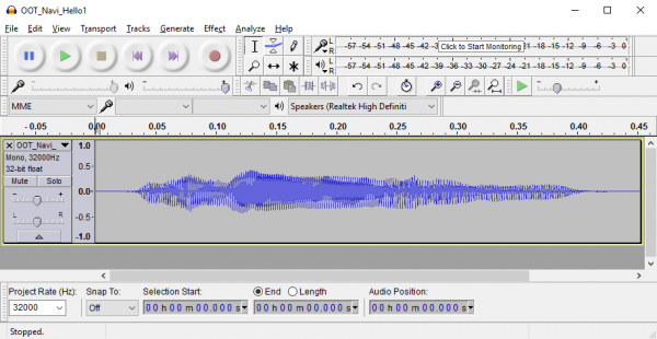
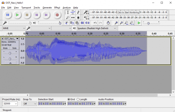
You’ll see, then, something like this show up. This is what your audio file looks like, to the computer. Again, don’t panic! Unless you want to edit the sound in some way (which we don’t), none of the settings or pieces of information that have popped up here matter to us.

Audacity with open file

Convert to OGG

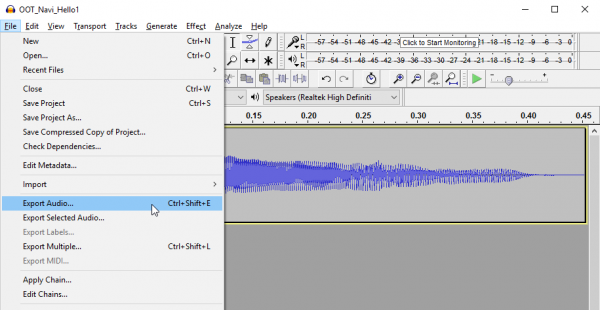
Now that you have the file loaded, you need to convert it to OGG Vorbis format. To do so, open the “File” menu and select the “Export Audio…” menu item about halfway down. A familiar looking save window should pop up.

Export command in file menu

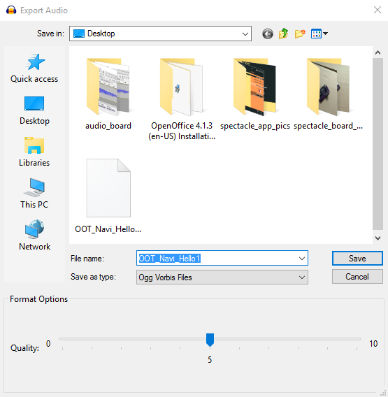
Right below the “File name:” field you’ll see a drop-down menus labeled “Save as type:”. Select “Ogg Vorbis Files” in that drop down.

A slider will appear at the bottom of the window. The default value of ‘5’ is probably good enough for most purposes. Click “Save” and another window will pop up.

Export audio frame

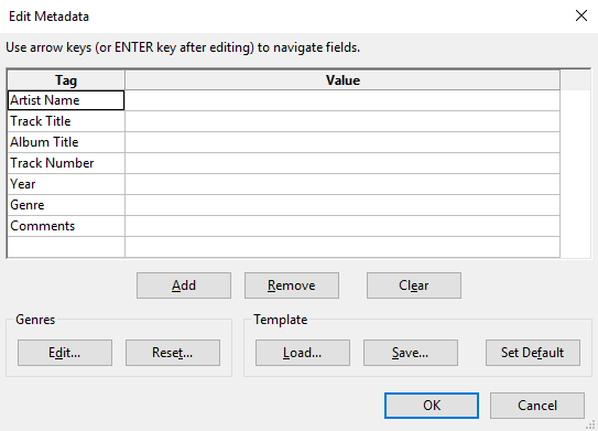
This one allows you to set metadata about the file. You can ignore everything and just click “OK” to skip past this.

Congratulations! You’ve successfully converted a file to OGG Vorbis format. You may now copy that file to the Micro SD card (don’t forget to rename it to a number!) for use with the Spectacle Audio Board.

Set metadata window

Extra credit- trimming the fat and making the sound louder

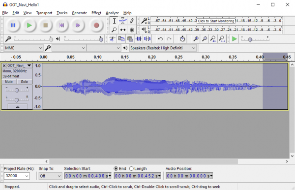
As you can see in my file above, there’s a great deal of room between the extents of the sound and the extents of the window. In the time (horizontal) axis, this manifests as flat lines before and after the content of the sound file. In the “loudness” (vertical) axis, this manifests as space between the top and bottom of the waveform file and the top and bottom of the playback position window.

File open in Audacity

Let’s eliminate some of that dead time before and after the sound plays. To do so, simply click inside the playback position window and drag, as though you are trying to select a section of text. The part you’ve selected will be highlighted, as above. Now, just hit the “Delete” key on your keyboard, and that section will be removed. Repeat the process at the other end of the sound.

Extra dead time highlighted

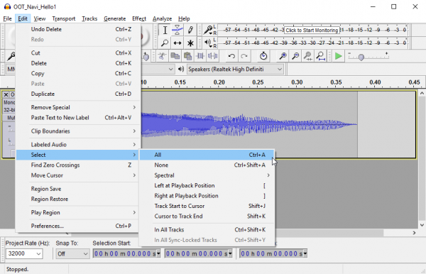
Now, let’s see what we can do about volume. Under the “Edit” menu, look for the “Select” submenu, and choose “All” to select the entire sound. You can also just use the drag-and-highlight method from above.

Finding the "Select All" menu option

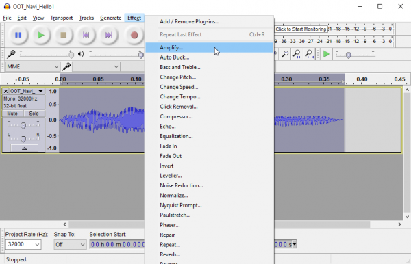
Now that you’ve got the entire sound selected, click on the “Effect” menu and select the “Amplify…” option.

Effects menu

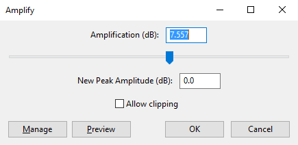
A new window will pop up with a slider, a couple of text boxes, and one checkbox. The slider will be pre-positioned to amplify the sound as much as possible without “clipping” it. “Clipping” occurs when you try to amplify a sound more than the system you’re playing it through can stand, and it results in a sort of grating buzzing noise during playback.

Amplify dialog box

You have a choice, now: you can either accept the system’s suggested level, or you can click on the “Allow Clipping” check box and increase the amplification more with the slider. I’ve chosen to accept the clipping limitation for the image above; comparing it to the image of the file higher up, you can see how I’ve trimmed the dead time at the ends and increased the amplitude vertically.

Why would you want to allow your sound to clip? Well, first of all, the preset amplification only takes into account the peak value of your sound, so if one small section of the audio is allowed to clip, it may allow the vast majority of the sound to be substantially louder. Secondly, if you’re playback device is of relatively poor quality, or the sound file itself is, allowing clipping may increase volume significantly without making the sound quality too much worse than it already is. Thirdly, volume intensity may be far more important than sound quality, and allowing clipping lets you push the volume as high as you can.

Edited sound

Now that you’ve successfully edited the sound, export it to OGG Vorbis as we covered above.

Example Project

Let’s use the contents of the Spectacle Light and Sound Kit to put together a working project! We’re going to set up a laser gun type setting, where a light comes on and a sound plays when a button is pressed, then the light goes off when the button is released.

Connect the boards

Start by connecting up the boards. All of the required hardware is included with the kit.

First, plug one end of one of the TRRS cables into the “Direct” jack on the Director Board.

The direct jack

Next, take the other TRRS cable and plug it into the “Program” jack on the Director Board.

The program jack

Take the other end of this cable and plug it into the audio jack of the phone, tablet, or computer that you’ll be using to program the system.

Into the phone jack

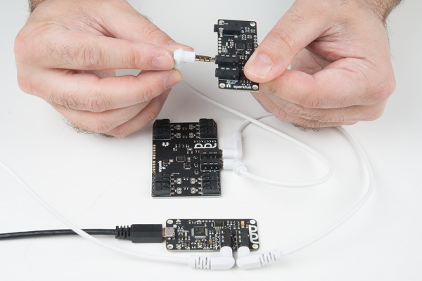
Then take the other end of the first TRRS cable (the one plugged into the “Direct” jack on the Director Board) and plug it into the “In” jack on the Button Board.

In jack on button board

Grab another of the TRRS cables and plug it into the “Out” jack on the Button Board.

Out jack on the director board

Plug the other end of that cable into the “In” jack on your Audio Board.

In jack on audio board

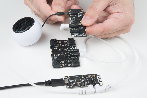
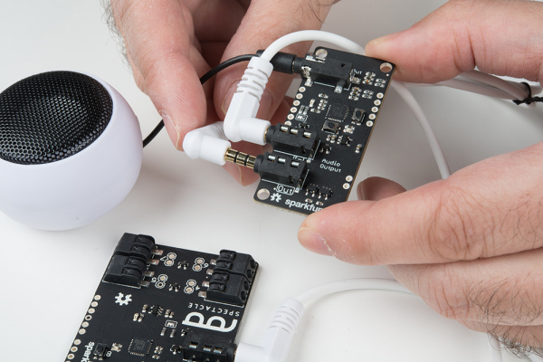
Now plug the speaker into the “Audio Out” jack on the Audio Board.

Plug the speaker into the audio board

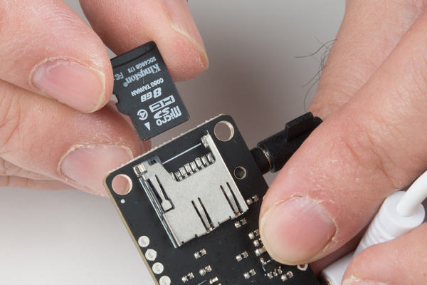
Insert the micro SD card into the Audio Board.

Inserting the micro SD card

Plug another of the TRRS cables into the “Out” jack on your Audio Board.

Out jack on the Audio Board

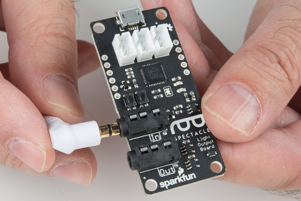
Plug the other end of that cable into the “In” jack on your Light Board.

Plugging into the in jack on the light board

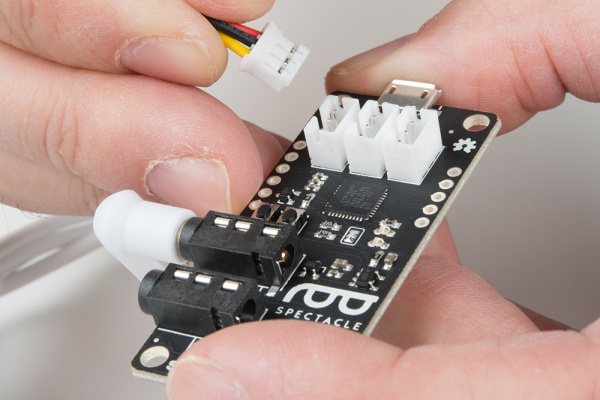
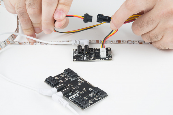
Connect the light strip adapter cable to the Light Board.

Connecting the light strip adapter

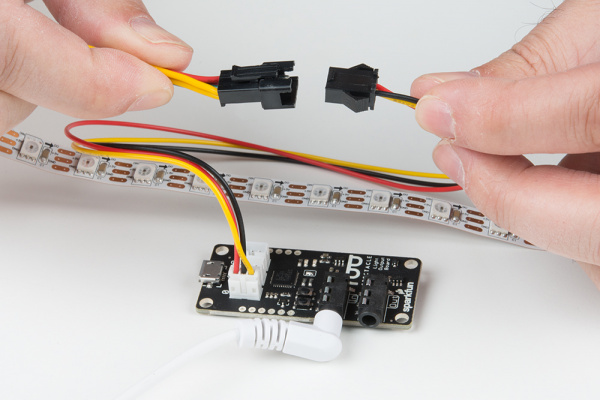
Connect the other end of the adapter cable to the light strip.

Connecting the light strip

Finally, plug the Micro B end of the USB cable into the Director Board and the other end into the power adapter. Plug the power adapter into the wall. You should see one solid light and one blinking light on the Light Board, the Audio Board, and the Button Board. On the Director Board, you’ll see one solid light and one light which blinks one time, then pauses, then repeats. This shows that power is present and the boards are up and running.

Setting up the board configuration

We’re going to assume that you followed the instructions on the previous page about converting sounds to OGG Vorbis format, and that there is a sound on the Micro SD card inserted into the Sound board named “00.ogg”. If this is not the case, take a few minutes to go back to that page and prepare a sound.

When you first open the Spectacle app webpage, this is what you’ll see. Your project name will differ from mine, as Spectacle assigns a random name to each project.

Blank project page

To continue, we must tell the project which boards we wish to use. Start by clicking the “Add a board” button at the bottom of the page.

add a board button

This will bring up a list of the available boards. We’re going to add our Button Board first of all, so click anywhere in the “Button” box to add it.

Now, repeat this process two more times, adding an Audio Board and a Light Board.

List of available boards

You should now have a list that looks like this, showing all three of the boards we’re going to use in this project. Pay attention to the order of the boards in the list! They must match the order of the boards in hardware! If the order of your boards differs from that in the image above, you can use the up and down carets (in the board name bar) to change the order of the boards.

All boards in place

Now you’ll need to add actions to each board, to tell the Spectacle system what sort of behavior you want. Click on the clapboard icon (highlighted above) for the Button Board to pull up the “Edit actions” frame.

Edit action buttons

This will pull up a window that looks like the above. I’ve highlighted the “Add an action” button. Click it to pull up a list of actions for the Button Board.

Add an action button

This list will pop up after you click the “Add an action” button. We’re going to add two actions: “Action on Press” and “Action on Release”. Click the “Action on Press” list item, then click “Add an action” again to pull the list back up, then click the “Action on Release” list item to add that action to the list.

Button board action list

Here you can see that we’ve added the two actions we want for our project. Note that, when added, the inputs default to being blank. You need to put a value in every field for the design to be valid.

Button board actions

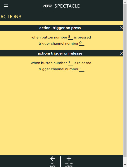
Here are the settings you’ll want to put into place for this project. You can see that the “Action on Press” is tied to channel 0, and we’re using button 8 (the onboard button) as the input signal. “Action on Release” is tied to channel 1, and also to button 8.

Button actions, filled in

Once you’ve filled in the fields for both actions, click the “Go Back” button to return to your list of boards. This will automatically save the changes you’ve made.

Go back button

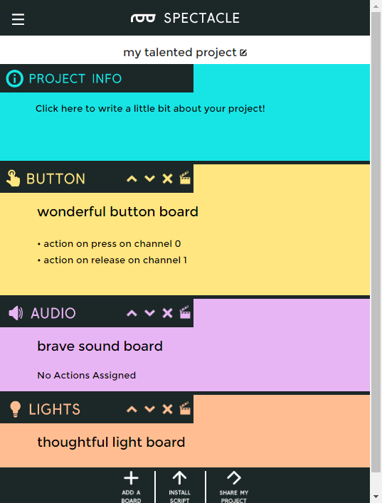
You can see here that the actions we added for the Button Board appear in the main board list, as a reminder of what each board has been configured to do.

Board list with actions on Button board

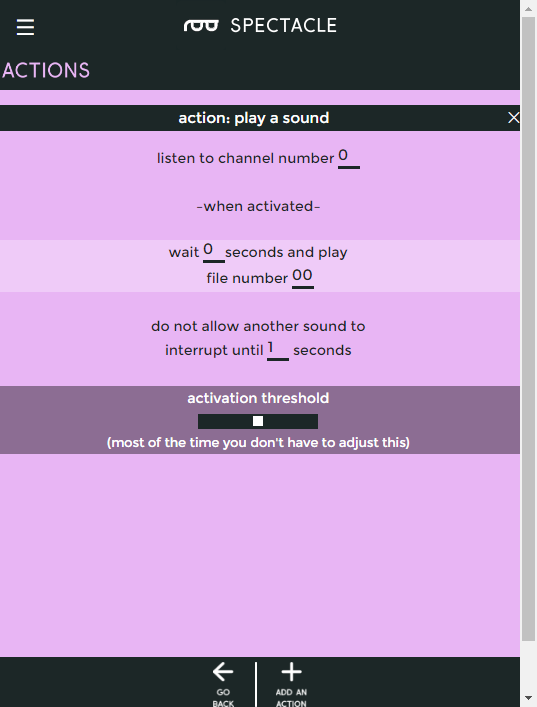
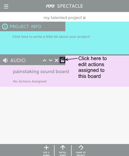
Now, add a “Play Sound” action to the Audio Board. It’s the only action the Audio Board supports. Fill in the blanks on the play sound page as shown above.

Play sound options

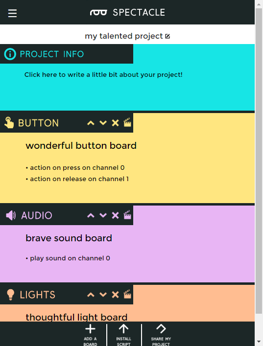
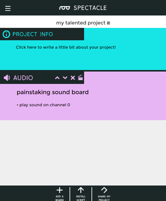
Back in the main frame, you’ll see that the play sound action has been added to the Audio Board’s section of the list.

Main frame with play sound action in place

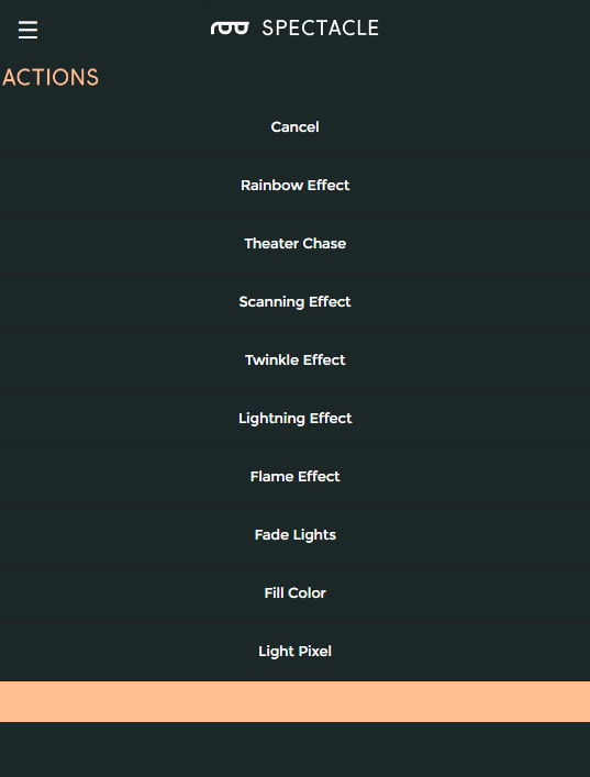
Finally, we’ll configure the Light Board. The picture above shows the full list of actions that the Light Board supports. We’re going to use the “Fill Color” option, twice, for our project.

Light board actions

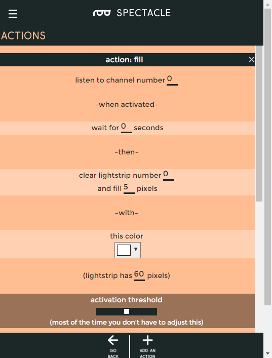
Below are the settings for the first “Fill Color” effect to be added. This turns the pixels on when the button is depressed.

Settings for the first fill effect

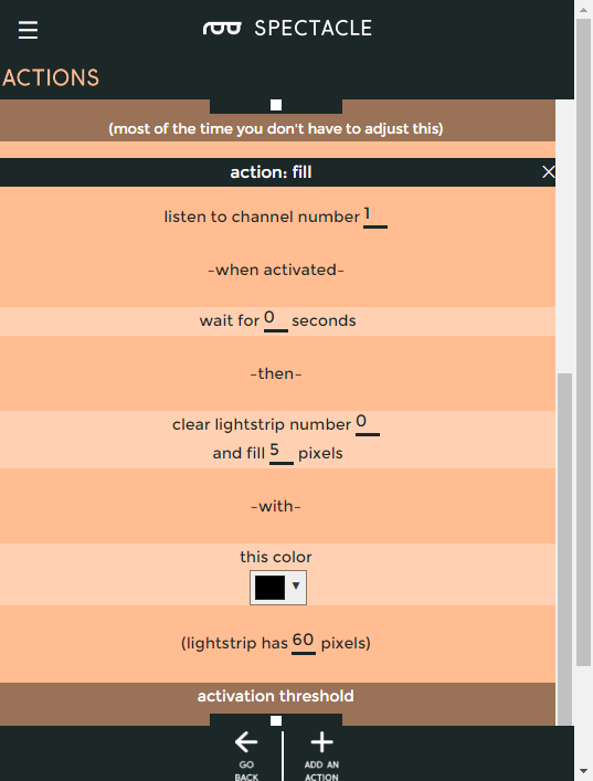
Here are the settings for the second fill effect. This turns the pixels off when the button is released.

You can now click the “Go Back” button to return to the main page.

Settings for second fill effect

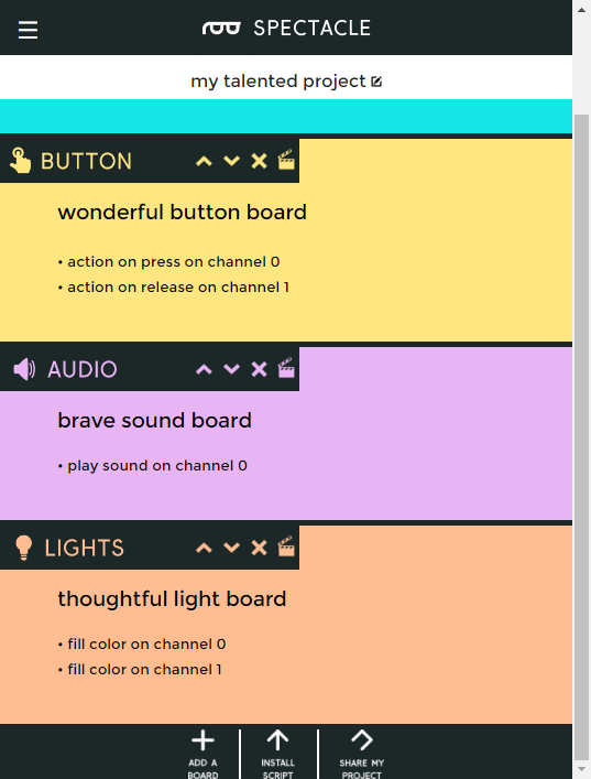
Congratulations! You’ve completed configuration of your first Spectacle project! Now let’s cover loading the configuration onto your Director Board.

Completed project

Uploading

Now that you’ve created your Spectacle program it’s time to upload it to the Director Board. If you followed the instructions above, your uploading device is connected to the board and ready to go, so all you need to do is touch the “Install Script” button at the bottom of the page. That will bring up the page seen below.

Upload page

Make sure the volume on your device is turned all the way up, and that no other audio source (music, video, etc) is playing in the background. Then press and hold the “RST” button on the Director Board, press and hold the “PROG” button, then release the “RST” button.

This will put the Director Board into program mode. You’ll see the light on the board blink three times, pause, then repeat. This is your visual indicator that the board is in program mode. Once you’ve established that the board is in program mode, you can begin programming by touching the “Install” button on the Spectacle app screen. The button will gray out during the programming process, which should only last for a few seconds. Once programming is done, you’ll see the light on the Director Board blink 10 times, pause, then repeat. That’s your cue that the program was uploaded successfully.

Press the “RST” button again to reset the system and begin the program!

If you have any troubles, visit the troubleshooting page for help resolving your issues.

Further Reading

For general Spectacle information, please check out the user guide:

New!

Spectacle User's Guide

May 4, 2017

The Spectacle system is designed to help those without electronics or programming experience integrate electronics into projects.

For more Spectacle fun, check out the additional tutorials below:

New!

Spectacle Audio Board Hookup Guide

All the information you need to use the Spectacle Audio Board in one place.
New!

Spectacle Light Kit Hookup Guide

All the information you need to use the Spectacle Light Kit in one place.
New!

Spectacle Light Board Hookup Guide

All the information you need to use the Spectacle Light Board in one place.
New!

Spectacle Inertia Board Hookup Guide

Everything you need to know about using the Spectacle Inertia Board in one place.
New!

Spectacle Example: Super Mario Bros. Diorama

A study in building an animated diorama (with sound!) using Spectacle electronics.
New!

Spectacle Motion Kit Hookup Guide

All the information you need to use the Spectacle Motion Kit in one place.
New!

Spectacle Motion Board Hookup Guide

All the information you need to use the Spectacle Motion Kit in one place.
New!

Spectacle Button Board Hookup Guide

All the information you need to use the Spectacle Button Board in one place.

learn.sparkfun.com |CC BY-SA 3.0 | SparkFun Electronics | Niwot, Colorado

micro:bit Breakout Board Hookup Guide

$
0
0

micro:bit Breakout Board Hookup Guide a learn.sparkfun.com tutorial

Available online at: http://sfe.io/t655

Introduction

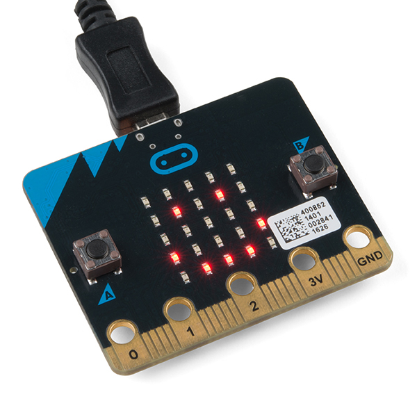
The micro:bit, by itself, offers a vast array of possibilities and potential projects, considering it includes an onboard temperature sensor, accelerometer, compass, LED array, Bluetooth radio, and more. However, when you’re ready to branch out beyond those initial capabilities, like connecting to an SD card for logging, you’ll need to break out some of the pins on the micro:bit’s card edge connector. For that, we’ve got you covered with the micro:bit Breakout Board.

SparkFun micro:bit Breakout (with Headers)

BOB-13989
5.49

There’s also a version without headers, if you care to solder your own or use wires instead.

Required Materials

To follow along with this project tutorial, you will need the following materials:

Suggested Reading

If you aren’t familiar with the following concepts, we recommend checking out these tutorials before continuing.

How to Solder: Through-Hole Soldering

This tutorial covers everything you need to know about through-hole soldering.

How to Use a Breadboard

Welcome to the wonderful world of breadboards. Here we will learn what a breadboard is and how to use one to build your very first circuit.

Light-Emitting Diodes (LEDs)

Learn the basics about LEDs as well as some more advanced topics to help you calculate requirements for projects containing many LEDs.

Getting Started With the micro:bit

The micro:bit is a compact, powerful programming tool that requires no software installation. Read on to learn how to use it YOUR way!

Hardware Overview

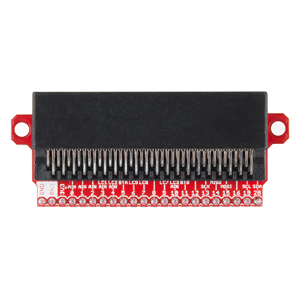
The micro:bit Breakout board allows you to utilize all of the pins on the micro:bit and opens up some previously inaccessible communication ports, like I2C and SPI.

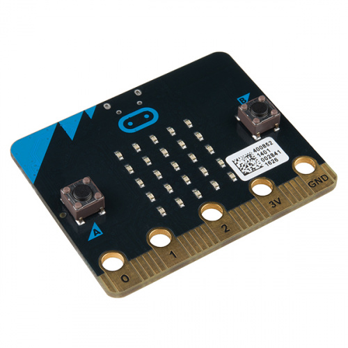
micro:Bit breakout

Top-down diagram of the micro:bit breakout board

Pins

Most of the micro:bit’s pins can be configured for one or more functions.

PinFunction 1Function 2Description
GNDGround
GNDGround
3V33.3V OUT
0Analog InConnected to large pin 0
1Analog InConnected to large pin 1
2Analog InConnected to large pin 2
3Analog InLED Column 1Controls part of LED array
4Analog InLED Column 2Controls part of LED array
5Button AConnected to Button A on micro:bit
6LED Column 9Controls part of LED array
7LED Column 8Controls part of LED array
8Open GPIO pin
9LED Column 7Controls part of LED array
10Analog InLED Column 3Controls part of LED array
11Button BConnected to Button B on micro:bit
12Open GPIO pin
13SCKGPIO or SPI clock
14MISOGPIO or SPI MISO
15MOSIGPIO or SPI MOSI
16Open GPIO pin
19SCLGPIO or I2 clock
20SDAGPIO or I2 data

Power Pin

The pin listed as 3V3 is output only. When you plug in a USB cable or battery pack, 3-3.3V will be avialable on that pin to use. If you try to apply 3.3V to the pin, the board will not turn on.

LCn Pins

The pins labeled with LCn (e.g. LC1, LC8) refer to pins that are used to control the LED array on the front of the micro:bit. You can use them as GPIO, but you’ll often get weird patterns to show up on the LEDs, or when you write to the LED array, you may see unexpected behavior. If you use them as GPIO, we recommend disabling the LED display.

Hardware Assembly

Attach Headers

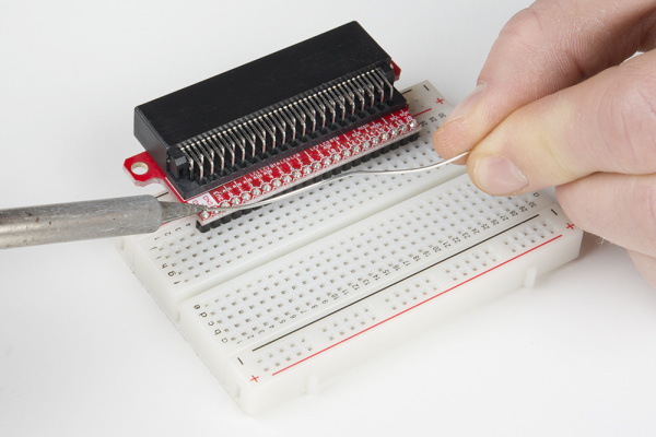
If you have the version of the breakout board without headers, solder some breakaway headers to the board. You can also solder wire directly to the breakout.

Solder headers to the micro:bit Breakout board

Build Example Circuit

Note: The micro:bit must be facing up in order to make electrical connections to the pins.

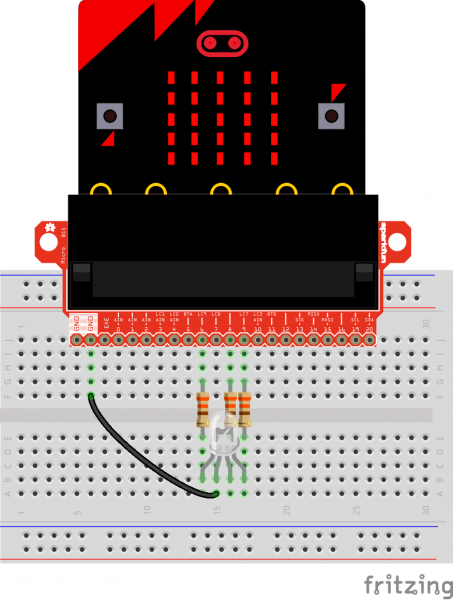
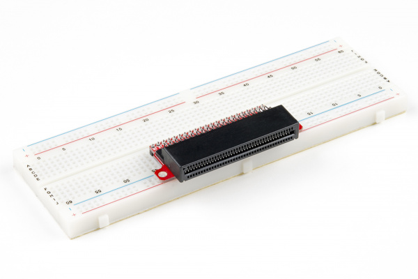
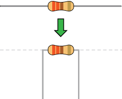
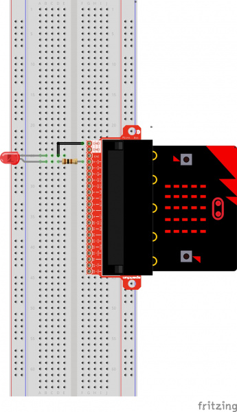
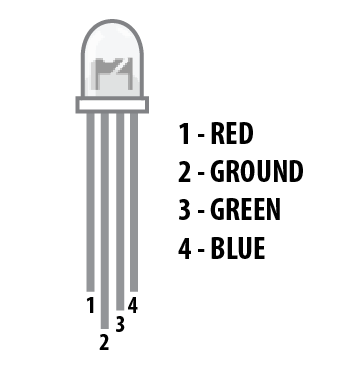
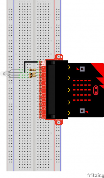
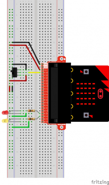
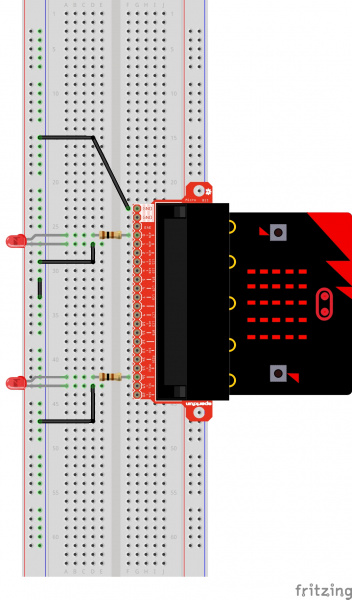
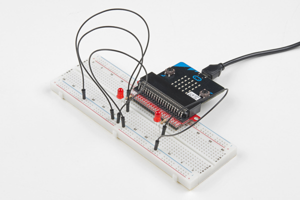
To begin, let’s light up an RGB LED. Attach the micro:bit to the breakout board, place the breakout board onto a breadboard, and connect an RGB LED through 330 Ω resistors. Use the image below to aid you in wire up the circuit.

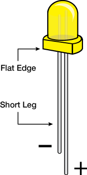
Remember, LEDs are polarized parts and can only work properly in one orientation. The longest leg of the LED goes where the black GND wire is in the circuit.

micro:bit breakout board hookup Fritzing

Having a hard time seeing the circuit? Click on the wiring diagram for a closer look.

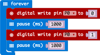
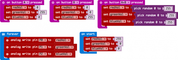
Example: Cycling Colors on an RGB LED

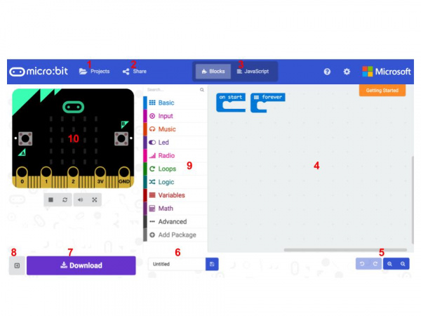
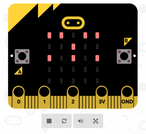
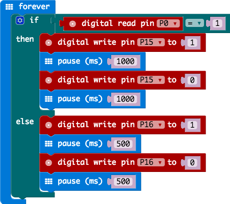
You can download the code from the emulator, or check out the project’s page here:


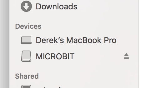
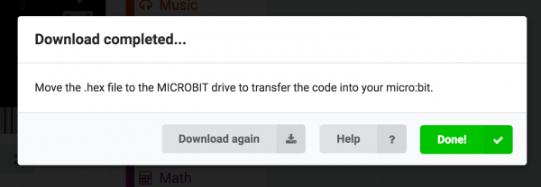
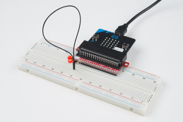
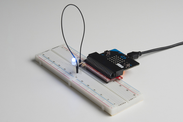
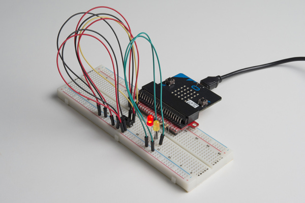
Copy the .hex file to your micro:bit drive, and you should see a fancy array of colors appear on your LED!

micro:bit cycling colors

Resources and Going Further

With the micro:bit breakout board, you can start introducing more sensors, lights, and motors into your project! For more information, check out these resources:

Need some inspiration for your next project? Check out some of these related tutorials:

HTU21D Humidity Sensor Hookup Guide

The HTU21D humidity sensor is an easy to use, digital, low-cost humidity sensor.

TSL2561 Luminosity Sensor Hookup Guide

The TSL2561 is an light sensor that's very inexpensive for the accuracy it provides. Here's how to use it.

Logomatic Hookup Guide

Basic introduction and hook-up guide for the SparkFun Logomatic.

HMC6343 3-axis Compass Hookup Guide

How to hook the HMC6343 -- a high-end, tilt-compensated compass module -- up to an Arduino. Never get lost again!

Using AT&T's M2X With the CC3000

A set of tutorials and examples to show how to connect an Arduino and CC3000 to AT&T's M2X data streams. We show how to post, fetch, and delete data. The final lesson is controlling an LED from an M2X stream.

LSM303C 6DoF Hookup Guide

A basic guide to get started with the LSM303C 6 Degrees of Freedom Breakout.

Blynk Board Washer/Dryer Alarm

How to configure the Blynk Board and app to notify you when your washer or dryer is done shaking.

Simultaneous RFID Tag Reader Hookup Guide

A basic guide to getting started with the RFID Tag Reader breakout and how to read and write multiple RFID tags over multiple feet!

learn.sparkfun.com |CC BY-SA 3.0 | SparkFun Electronics | Niwot, Colorado

ACS712 Low Current Sensor Hookup Guide

$
0
0

ACS712 Low Current Sensor Hookup Guide a learn.sparkfun.com tutorial

Available online at: http://sfe.io/t441

Introduction

The ACS712 is a handy little current sensor from Allegro MicroSystems for low to moderate current sensing applications. SparkFun offers two flavors of breakout board, one with just the sensor and another with an on-board amplifier to increase the sensitivity.

SparkFun Hall-Effect Current Sensor Breakout - ACS712

BOB-08882
7.95
3
SparkFun Low Current Sensor Breakout - ACS712

SEN-08883
11.95
8

The ACS712 sensor uses a Hall effect sensor to output a voltage relative to the current flowing through the IP+ and IP- pins. The advantage of using a Hall effect sensor is that the circuit being sensed and the circuit reading the sensor are electrically isolated. This means that, although your Arduino is running on 5V, the sensed circuit can be operating at higher DC or AC voltages!

The amplified breakout board is capable of sensing very small currents down to around 10mA and large currents up to 5A! However, since the output is analog, your usable readings will be limited by noise and the resolution of the ADC reading the output. This sensor is not recommended for current sensing lower than 10’s of milliamps.

Required Materials

Depending on the equipment available to you, you will need some of the following items to follow along with this hookup guide:

Suggested Reading

Here are some topics related to this hookup guide you may want to review:

The Hall Effect and Current Sensors

This section provides a quick recap of electromagnetic concepts that make this current sensor possible. How does this little chip take current from one circuit and produce a proportional output voltage without physically connecting the two circuits?

Faraday’s Law of Induction

In the ACS712, sensing current starts with a phenomena known as Faraday’s Law (of Induction). This phenomena, first discovered by Michael Faraday in 1831, is a foundation of modern radio and electromagnetics. This law describes how an electrical current flowing in a conductor creates a surrounding magnetic field, and how a changing magnetic field can create, or induce, a current in a conductor. This is how antennas pick up radio waves!

Faraday's Law

This image illustrates the magnetic field created around a conductor with a current flowing through it (Photo courtesy of http://www.tesla-institute.com)

The current pins of the ACS712 are internally connected to a big trace of copper, allowing a lot of electricity to flow through this part of the chip. When current flows through the copper strip, a magnetic field is created around the trace with a strength proportional to the current.

The Hall Effect

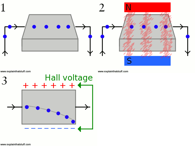
The next step in sensing current is based on the Hall effect - a very useful phenomena discovered by Edwin Hall in 1879. In basic terms, the Hall effect produces a voltage difference across a conductor in the presence of a magnetic field. This provides a neat way of sensing nearby magnetic fields and has many applications. Hall effect sensors are used in some car engines to detect where in a rotation cycle the camshaft or crankshaft are, for example.

Hall Effect Animation

This animation shows how a magnetic field creates a voltage difference. The blue circles are electrons flowing (Photo courtesy of http://www.explainthatstuff.com/hall-effect-sensors.html

The ACS712 has an internal Hall effect sensor placed next to the aforementioned copper strip. When current flows through this copper strip, a magnetic field is created. This magnetic field is then sensed by the Hall effect sensor and produces a voltage output that is proportional to the input current!

Hall Effect current sensor

This shows how the current sensor looks internally (Photo courtesy of Allegro Micro)

This method of sensing allows the sensing circuit to be electrically isolated from the sensed circuit. Practically, this means that since the circuits aren’t physically connected, you can use a low-power Arduino to measure the current going through a high power device, even one that uses AC power!

Hardware Overview

This section will explore the various segments of the breakout.

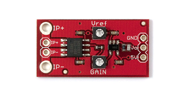
ACS712 Board Picture

ACS712 Breakout Details:

  • Analog output with bandwidth adjustable to 80kHz.
  • The bandwidth on the ACS712 Low Current Sensor Breakout with filter has been set to 34kHz to reduce noise when using at high gains. The full 80KHz bandwidth that the sensor is capable of can be recovered by removing C1. See schematic for more details.
  • Measures DC and AC currents from around 10mA up to 5A
  • Adjustable sensitivity with on-board amplifier, gain from 4.27 to 47 V/V
  • The version without the op-amp has a base sensitivity of 185mV/A
  • Full electrical isolation of measured and sensed circuits
Please Note: Although the chip itself is rated for up to 2.1kV (RMS) of isolation, the board has not been designed for such high voltage applications.

Below is a list of all the pins broken out on the ACS712 and their function.

SymbolDescription
IP+High side of current sensor
IP-Low side of current sensor
GNDMust be connected to ground
VoVoltage output proportional to current flowing through IP+ and IP-
5V5V power supply

To measure a current using this device, the current must flow through the IP+ terminal and out the IP- terminal (it will work in the other direction, but the measurement will be negative). IE: These terminals must be in series with the circuit the measured current is flowing through. Note that both IP+ and both IP- terminals are connected to each other, you can use either (or both) of them.

This amplified version of the breakout board has two potentiometers on it: Vref and Gain

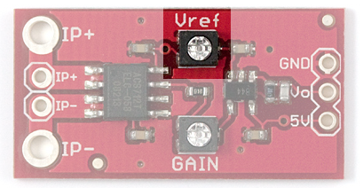
The Vref potentiometer sets the baseline voltage output. In other words, it adjusts the voltage seen at Vo when there is no current flowing through the sensor (0 mA). This allows the sensor to output negative current readings as well as positive.

ACS712 Vref Potentiometer

Vref potentiometer, highlighted

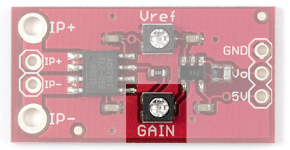
The gain potentiometer sets the sensitivity of the device. For example, if the gain is set high, then a smaller current will cause the voltage output to increase more, giving you higher sensitivity and allowing you to sense smaller currents.

ACS712 Gain Potentiometer

Gain potentiometer, highlighted

However there are a couple caveats:

  1. With higher gain you will see more noise (spikes) on the output, so smaller currents will be harder to measure accurately.
  2. If you are trying to measure larger currents with a high gain setting, your output will saturate or clip and reach the maximum 5V or 0V.

With that in mind, to get meaningful data from the current sensor, you must configure the Vref and gain potentiometers properly.

Calibration and Example Code

An example sketch for Arduino is included below to help you get started with the ACS712. It will help you set the potentiometers and perform calculations to convert raw ADC readings into the actual current in mA.

To properly calibrate the ACS712 breakout board, you should first consider what type and range of currents you will want to measure.

Choosing the Range

If you are going to be dealing mainly with DC, positive currents, you can adjust Vref to the lower end of its range. If you are trying to measure AC currents, you will want to keep Vref about in the middle at 2.5V. This lets your output swing equally in the positive and negative directions.

The gain setting will depend on the range of currents you want to measure. If you want to measure a current between 100mA and 500mA, you will want to set the gain so the sensitivity is something like 250mV/100mA (you will learn how to do this in the following steps).

Setting Vref

To get started, copy and upload the sketch below to your Arduino. You can also find the latest files in the GitHub repository.

language:c
/*  SparkFun ACS712 Demo
    Created by George Beckstein for SparkFun
    4/30/2017

    Uses an Arduino to set up the ACS712 Current Sensor
    See the product page at: https://www.sparkfun.com/products/8883

    Parts you may need:
    - 100 Ohm, 1/2W or greater resistor OR two 220 Ohm 1/4 resistors in parallel
    - ACS712 Breakout with on-board amplifier

    Optional equipment:
    - Oscilloscope
    - Multimeter (or two)
    - A power supply with current limiting/constant current would be handy to calibrate the device without using resistors
*/

const int analogInPin = A0;

// Number of samples to average the reading over
// Change this to make the reading smoother... but beware of buffer overflows!
const int avgSamples = 10;

int sensorValue = 0;

float sensitivity = 100.0 / 500.0; //100mA per 500mV = 0.2
float Vref = 2500; // Output voltage with no current: ~ 2500mV or 2.5V

void setup() {
  // initialize serial communications at 9600 bps:
  Serial.begin(9600);
}

void loop() {
  // read the analog in value:
  for (int i = 0; i < avgSamples; i++)
  {
    sensorValue += analogRead(analogInPin);

    // wait 2 milliseconds before the next loop
    // for the analog-to-digital converter to settle
    // after the last reading:
    delay(2);

  }

  sensorValue = sensorValue / avgSamples;

  // The on-board ADC is 10-bits -> 2^10 = 1024 -> 5V / 1024 ~= 4.88mV
  // The voltage is in millivolts
  float voltage = 4.88 * sensorValue;

  // This will calculate the actual current (in mA)
  // Using the Vref and sensitivity settings you configure
  float current = (voltage - Vref) * sensitivity;

  // This is the raw sensor value, not very useful without some calculations
  //Serial.print(sensorValue);

  /*************************************************************************************
   * Step 1.)
   * Uncomment and run the following code to set up the baseline voltage
   * (the voltage with 0 current flowing through the device).
   * Make sure no current is flowing through the IP+ and IP- terminals during this part!
   *
   * The output units are in millivolts. Use the Arduino IDE's Tools->Serial Plotter
   * To see a plot of the output. Adjust the Vref potentiometer to set the reference
   * voltage. This allows the sensor to output positive and negative currents!
   *************************************************************************************/

  Serial.print(voltage);
  //Serial.print("mV");

  /*************************************************************************************
   * Step 2.)
   * Keep running the same code as above to set up the sensitivity
   * (how many millivolts are output per Amp of current.
   *
   * This time, use a known load current (measure this with a multimeter)
   * to give a constant output voltage. Adjust the sensitivity by turning the
   * gain potentiometer.
   *
   * The sensitivity will be (Vreading - Vref)/(known current).
   *************************************************************************************/

    /*************************************************************************************
   * Step 3.)
   * Comment out the code used for the last two parts and uncomment the following code.
   * When you have performed the calibration steps above, make sure to change the
   * global variables "sensitivity" and "Vref" to what you have set up.
   *
   * This next line of code will print out the calculated current from these parameters.
   * The output is in mA
   *************************************************************************************/

  //Serial.print(current);
  //Serial.print("mA");


  // -- DO NOT UNCOMMENT BELOW THIS LINE --
  Serial.print("\n");

  // Reset the sensor value for the next reading
  sensorValue = 0;
}

This sketch reads the voltage on pin A0 and prints it to the serial terminal. In later steps you will learn how to get actual current readings with this sketch.

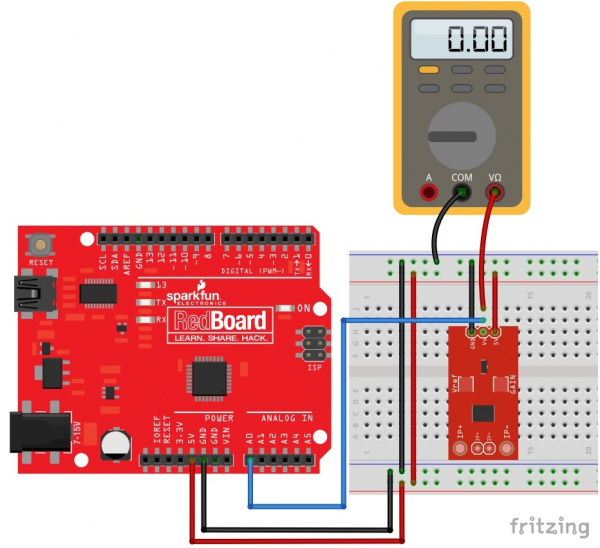
To set up Vref, the sensor should have no current flowing through it! For this part, you only need to connect the ACS712’s GND pin to Ground, Vo pin to pin A0 on the SparkFun RedBoard (or equivalent), and 5V to the 5V pin on the RedBoard. If you have one available, it may be useful to also read the output voltage using a multimeter. See the Fritzing diagram below for more information:

Adjusting Vref Circuit

Having a hard time seeing the circuit? Click on the wiring diagram for a closer look.

If you aren’t using a multimeter to set Vref, open up the Arduino IDE’s serial plotter by clicking Tools->Serial Plotter. This will show the voltage reading from the Arduino in real time. The units are in millivolts.

Turn the Vref potentiometer clockwise to increase Vref and counter-clockwise to decrease. Make small adjustments, as the adjustment is very sensitive!

Note: Using metal/magnetized screwdrivers may cause the sensor to give false readings. This is because the Hall effect sensor inside is picking up the magnetic fields from the screwdriver. You may want to use a plastic screwdriver to eliminate this effect. I made one out of an old guitar pick with some scissors!

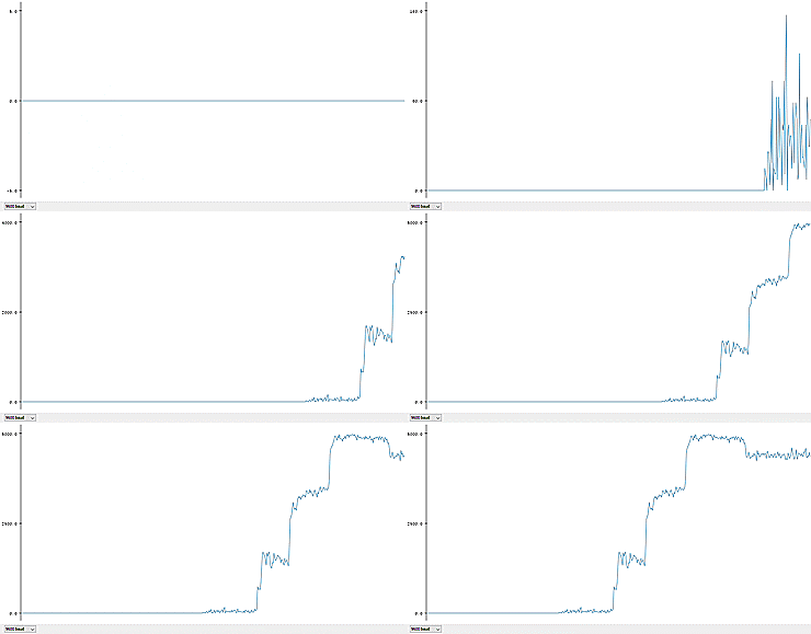
In the Serial Plotter, you should see something like this:

Vref Animation

Using the RedBoard and Arduino, you can plot the output voltage as you adjust Vref

Tune Vref to about where you want it, for example 2500mV.

Setting Gain and Sensitivity

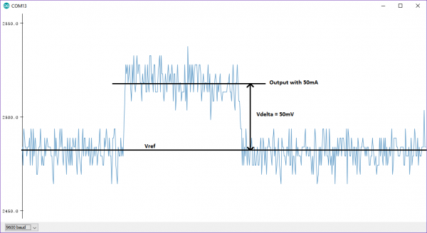
To set the gain, you need to pass a known current through the sensor and tune the gain pot to achieve the sensitivity your application needs.

For example, if you want to measure between 100mA and 500mA, you should shoot for a sensitivity of around 250mV/100mA. To do this, you can pass 100mA through the sensor, and adjust the gain pot until the output voltage is 250mV above your set Vref.

For those of you who have a benchtop power supply with a current limiter/constant current (CC) mode, getting this 100mA current is easy. In this case, you can simply connect the positive terminal of the power supply to the IP+ pin and the negative terminal of the power supply to the IP- pin. Make sure your current limit is set to something reasonable (NOT above 5A), and turn the power on. Adjust the output to a constant 100mA current for use in adjusting the gain. Make sure your benchtop power supply won’t be damaged by shorting the outputs, read your supply’s user manual for more information

If you don’t have a power supply, all you need are some resistors (like in this nifty resistor kit, or these power resistors for more power dissipation). To make a fixed, known current, just use Ohm’s Law!

If you want a 100mA current from a 5V source you need (5/0.1) = 50Ω

You should keep in mind how much power your resistors can handle though! If not, they’ll end up a bit toasty… With 5V and 100mA, the power would be 500mW or 1/2W. The small resistors in the kit above can only handle 250mW or 1/4W at most. But, wait! A resourceful engineer knows you can still use the 1/4W resistors, you just need to split the power dissipation. By placing equal resistors in parallel, you can increase the maximum allowable power dissipation; each resistor just adds their power rating. IE: 1/4W resistor + 1/4W resistor = 1/2W capacity! Keep in mind that the equivalent resistance will be lower though.

500mW is still a lot of power for these 1/4W resistors, so I recommend using only 50mA to tune the gain, unless you have the power resistors linked to above.

To get 50mA from 5V, you need 100Ω. Using parallel resistances, you need double that, or around 220Ω. You may want to use your multimeter to make sure the current flowing through the circuit is indeed 50mA. The tolerances of resistors can alter this current. To measure current with your multimeter, make sure to connect it in series! To see a diagram of how to build the circuit for setting the gain, see the Fritzing diagram below:

Adjusting Gain Circuit

Having a hard time seeing the circuit? Click on the wiring diagram for a closer look.

With a known, constant current flowing through the sensor, the gain can be adjusted. The same sketch can be used as last time. Open up the Serial Plotter again. To set the gain, disconnect one of the wires to break the current sensing circuit, when you reconnect it, see how much the output voltage increases. Subtract this from your Vref, to keep the voltage change (also known as delta). So, if you have 50mA flowing in the circuit, you want this change to be about 125mV for the 250mV/100mA sensitivity example. An example is shown below:

Gain Adjust Delta Plot

Adjust the change (Vdelta) to what you need it to be by tuning the gain potentiometer. As mentioned above, this affects the noise (spikiness) you see in the output:

Gain Adjust Noise

As the gain increases, the spiky noise gets bigger (and the Vref changes slightly)

Note: Adjusting the gain pot also changes the Vref setting slightly, you need to take this into account when you do your calculations. You should measure your final Vref and sensitivity with a multimeter after calibration.

Once you have Vref and the sensitivity settings selected, you can modify the code in the example sketch to print out your current readings in milliamps! Follow step 3 in the code comments to learn how to do this. Make sure to change the sensitivity and Vref variables to what you have set so the code can calculate the current properly.

Resources and Going Further

The ACS712 sensor is ideal if you need to measure a small to moderate amount of current, especially if it’s AC current! For more information about the ACS712, check out the links below:

If you don’t need electrical isolation and want to measure smaller currents, check out the INA169 Breakout Board. And for even higher power applications, check out the Non-Invasive Current Sensor - 30A.

For more power related learning, check out the tutorials below:

Battery Technologies

The basics behind the batteries used in portable electronic devices: LiPo, NiMH, coin cells, and alkaline.

Mini FET Shield Hookup Guide

Learn how to hookup and use the FET shield for Arduino Pro Mini 3.3V. With this shield, you can control much larger loads such as motors or large LED strips without straining your Arduino's power.

Adding a Timed Button to a Project

This tutorial will walk you through making a timed power controller for interactive projects. You will learn how to add an on button that will provide power to your project for an amount of time and then turn off again.

Beefcake Relay Control Hookup Guide

This is a guide for assembling and basic use of the Beefcake Relay Control board

learn.sparkfun.com |CC BY-SA 3.0 | SparkFun Electronics | Niwot, Colorado

ZX Distance and Gesture Sensor SMD Hookup Guide

$
0
0

ZX Distance and Gesture Sensor SMD Hookup Guide a learn.sparkfun.com tutorial

Available online at: http://sfe.io/t521

Introduction

The ZX Distance and Gesture Sensor is a collaboration product with XYZ Interactive. The innovative people at XYZ Interactive have created a unique technology that allows for simple infrared (IR) beams to be used to detect an object’s location in two dimensions.

The ZX Sensor is a touchless sensor that is capable of looking for simple gestures in the air above the sensor (e.g. swipe left or swipe right). Additionally, the sensor can also recognize the distance of an object away from the sensor at distances up to about 12 inches (30 cm), referred to as the “Z” axis, and the location of the object from side to side across the sensor in about a 6 inch (15 cm) span, referred to as the “X” axis.

ZX Distance and Gesture Sensor

SEN-13162
24.95

Covered in This Tutorial

We can use I2C or UART to communicate with the ZX Sensor. In this tutorial, we will show you how to connect the sensor to an Arduino or Arduino-compatible board as well as a computer so you can start creating gestures to handle all our your daily tasks or add some interactive flair to your project.

Materials Used

In addition to the sensor itself, you will need a few extra components to follow along with the Arduino examples:

If you would like to try the ZX Sensor on a Windows-based PC, you will need an FTDI Breakout:

SparkFun FTDI Basic Breakout - 5V

DEV-09716
14.95
94

Recommended Reading

There are a few concepts that you should be familiar with before getting started with the ZX Sensor. Consider reading some of these tutorials before continuing:

  • What is an Arduino?– Two of the examples use an Arduino to control the ZX Sensor
  • I2C– I2C is the one of the protocols used by the ZX Sensor
  • Serial Communication– We use serial communications to program the Arduino, view debugging information, and transmit data from the ZX Sensor
  • How to Use a Breadboard– The breadboard ties the Arduino to the ZX Sensor
  • How to Install FTDI Drivers– If you are programming an Arduino or using the ZX Sensor demo app, chances are you will need to use an FTDI

Board Overview

The ZX Sensor works by bouncing infrared (IR) beams of light from the two LEDs on either side off of an object above the sensor. The bounced light returns to the receiver in the center of the sensor, and a microcontroller on the back of the sensor interprets the data. We can read the results using an I2C or UART connection.

Pin Descriptions

The ZX Sensor gives us two ports to connect to: I2C and UART. You can see both ports are broken out to the 0.1" thru holes. See the table below for a list of each pin and its function.

ZX FRONT

Pin LabelDescription
GRNNot used
TXOUART transmit out from the ZX Sensor
RXIUART receive. Not used at this time.
VCC3.3 - 5 V power supply
GNDConnect to ground
BLKNot used, but connected to GND
DRData Ready. High when there is data to be read via I2C
CLI2C clock
DAI2C data

Setting the Jumpers

The ZX Sensor has a couple of jumpers on the back of the board that can be opened or closed with a soldering iron.

ZX Sensor Back

I2C Pullups

The ZX Sensor, by default, comes with 4.7 kΩ pull-up resistors on the SDA and SCL I2C lines. Remove the solder on this jumper using solder wick to disconnect the pull-ups.

I2C Addr

By default, this jumper is open. Close it to change the I2C address of the sensor.

JumperI2C Address
Open0x10
Closed0x11

Hardware Hookup

Add Headers

Solder a row of male headers to the nine headers holes on the board.

alt text

To keep the board from tilting while soldering, place the unused break away headers sideways under the board.

alt text

Heads up! Do not solder headers to the row of holes at the top of the board. Those are for programming the PIC micrcontroller.

Connect the Breakout Board

For the Arduino examples, we will be using I2C. Connect the breakout board to the following RedBoard pins:

ZX Sensor to Arduino Fritzing diagram

ZX SensorRedBoard
VCC5V
GNDGND
DR2
CLA5
DAA4

Note that we connect the DR pin, but we will only use it in the Arduino: Gesture Example. DR stands for “Data Ready,” which is active high whenever data is ready to be read from the ZX Sensor. We can attach this to an Arduino interrupt so we don’t have to continuously poll the sensor.

ZX Sensor connected to Redboard

Arduino Library Installation

All of the hard work for the ZX Sensor is being accomplished in the microcontroller on the sensor itself. All we need to do is read the results! We have created an Arduino library to make that even easier for you. Click the button to download the latest version of the ZX Sensor Arduino Library.

Download the ZX Sensor Arduino Library!

Unzip the downloaded file. Follow this guide on installing Arduino libraries to install the files as an Arduino library.

Arduino: ZX Example

Load the ZX Demo

Open up the Arduino program and select File → Examples → SparkFun_ZX_Distance_and_Gesture_Sensor → I2C_ZX_Demo.

I2C ZX Demo

Attach a USB mini cable from your computer to the RedBoard. If you have not previously done so, install the FTDI drivers.

For reference, here is the I2C_ZX_Demo.ino sketch.

language:c
    /****************************************************************
    I2C_ZX_Demo.ino
    XYZ Interactive ZX Sensor
    Shawn Hymel @ SparkFun Electronics
    May 6, 2015
    https://github.com/sparkfun/SparkFun_ZX_Distance_and_Gesture_Sensor_Arduino_Library

    Tests the ZX sensor's ability to read ZX data over I2C. This demo
    configures the ZX sensor and periodically polls for Z-axis and X-axis data.

    Hardware Connections:

     Arduino Pin  ZX Sensor Board  Function
     ---------------------------------------
     5V           VCC              Power
     GND          GND              Ground
     A4           DA               I2C Data
     A5           CL               I2C Clock

    Resources:
    Include Wire.h and ZX_Sensor.h

    Development environment specifics:
    Written in Arduino 1.6.3
    Tested with a SparkFun RedBoard

    This code is beerware; if you see me (or any other SparkFun
    employee) at the local, and you've found our code helpful, please
    buy us a round!

    Distributed as-is; no warranty is given.
    ****************************************************************/

    #include <Wire.h>
    #include <ZX_Sensor.h>

    // Constants
    const int ZX_ADDR = 0x10;  // ZX Sensor I2C address

    // Global Variables
    ZX_Sensor zx_sensor = ZX_Sensor(ZX_ADDR);
    uint8_t x_pos;
    uint8_t z_pos;

    void setup() {

      uint8_t ver;

      // Initialize Serial port
      Serial.begin(9600);
      Serial.println();
      Serial.println("-----------------------------------");
      Serial.println("SparkFun/GestureSense - I2C ZX Demo");
      Serial.println("-----------------------------------");

      // Initialize ZX Sensor (configure I2C and read model ID)
      if ( zx_sensor.init() ) {
        Serial.println("ZX Sensor initialization complete");
      } else {
        Serial.println("Something went wrong during ZX Sensor init!");
      }

      // Read the model version number and ensure the library will work
      ver = zx_sensor.getModelVersion();
      if ( ver == ZX_ERROR ) {
        Serial.println("Error reading model version number");
      } else {
        Serial.print("Model version: ");
        Serial.println(ver);
      }
      if ( ver != ZX_MODEL_VER ) {
        Serial.print("Model version needs to be ");
        Serial.print(ZX_MODEL_VER);
        Serial.print(" to work with this library. Stopping.");
        while(1);
      }

      // Read the register map version and ensure the library will work
      ver = zx_sensor.getRegMapVersion();
      if ( ver == ZX_ERROR ) {
        Serial.println("Error reading register map version number");
      } else {
        Serial.print("Register Map Version: ");
        Serial.println(ver);
      }
      if ( ver != ZX_REG_MAP_VER ) {
        Serial.print("Register map version needs to be ");
        Serial.print(ZX_REG_MAP_VER);
        Serial.print(" to work with this library. Stopping.");
        while(1);
      }
    }

    void loop() {

      // If there is position data available, read and print it
      if ( zx_sensor.positionAvailable() ) {
        x_pos = zx_sensor.readX();
        if ( x_pos != ZX_ERROR ) {
          Serial.print("X: ");
          Serial.print(x_pos);
        }
        z_pos = zx_sensor.readZ();
        if ( z_pos != ZX_ERROR ) {
          Serial.print(" Z: ");
          Serial.println(z_pos);
        }
      }
    }

Run

Make sure you have the correct serial port selected under Tools → Serial Port and “Arduino Uno” selected under Tools → Board. If you have never used the Arduino IDE before, this turoial should get you started.

Click the Upload button and wait for the program to finish uploading to the Arduino. Select Tools → Serial Monitor to open up the serial terminal. More info on the Serial Terminal can be found here. Note that the Serial Monitor settings are the default settings (9600, 8, n, 1). You should see a couple of messages noting that “ZX Sensor initialization complete.”

ZX Sensor initialization

Hover your hand 4 to 10 inches (10 to 25 cm) above the sensor.

Hover

Move your hand around above the sensor, and you should see Z (height above the sensor) and X (position side to side) appear in the serial terminal.

ZX Sensor showing position data

NOTE: Z- and X- data is given as an unsigned integer between 0 and 240 (inclusive).

Arduino: Gesture Example

Load the Gesture Interrupt Demo

In addition to providing Z- and X- axis data about an object, the ZX Sensor is also capable of detecting simple gestures. To see an example of this, open File → Examples → SparkFun_ZX_Distance_and_Gesture_Sensor → I2C_Gesture_Interrupt.

ZX Sensor Gesture Demo

Here is the I2C_Gesture_Interrupt.ino sketch for reference.

language:c
/****************************************************************
I2C_Gesture_Interrupt.ino
XYZ Interactive ZX Sensor
Shawn Hymel @ SparkFun Electronics
May 6, 2015
https://github.com/sparkfun/SparkFun_ZX_Distance_and_Gesture_Sensor_Arduino_Library

Tests the ZX sensor's ability to read gesture data over I2C using
an interrupt pin. This program configures I2C and sets up an
interrupt to occur whenever the ZX Sensor throws its DR pin high.
The gesture is displayed along with its "speed" (how long it takes
to complete the gesture). Note that higher numbers of "speed"
indicate a slower speed.

Hardware Connections:

 Arduino Pin  ZX Sensor Board  Function
 ---------------------------------------
 5V           VCC              Power
 GND          GND              Ground
 A4           DA               I2C Data
 A5           CL               I2C Clock
 2            DR               Data Ready

Resources:
Include Wire.h and ZX_Sensor.h

Development environment specifics:
Written in Arduino 1.6.3
Tested with a SparkFun RedBoard

This code is beerware; if you see me (or any other SparkFun
employee) at the local, and you've found our code helpful, please
buy us a round!

Distributed as-is; no warranty is given.
****************************************************************/

#include <Wire.h>
#include <ZX_Sensor.h>

// Constants
const int ZX_ADDR = 0x10;    // ZX Sensor I2C address
const int INTERRUPT_NUM = 0; // Pin 2 on the UNO

// Global Variables
ZX_Sensor zx_sensor = ZX_Sensor(ZX_ADDR);
volatile GestureType gesture;
volatile bool interrupt_flag;
uint8_t gesture_speed;

void setup() {

  uint8_t ver;

  // Initialize gesture to no gesture
  gesture = NO_GESTURE;

  // Initialize Serial port
  Serial.begin(9600);
  Serial.println();
  Serial.println("---------------------------------------------");
  Serial.println("SparkFun/GestureSense - I2C Gesture Interrupt");
  Serial.println("Note: higher 'speed' numbers mean slower");
  Serial.println("---------------------------------------------");

  // Initialize ZX Sensor (configure I2C and read model ID)
  if ( zx_sensor.init(GESTURE_INTERRUPTS) ) {
    Serial.println("ZX Sensor initialization complete");
  } else {
    Serial.println("Something went wrong during ZX Sensor init!");
  }

  // Read the model version number and ensure the library will work
  ver = zx_sensor.getModelVersion();
  if ( ver == ZX_ERROR ) {
    Serial.println("Error reading model version number");
  } else {
    Serial.print("Model version: ");
    Serial.println(ver);
  }
  if ( ver != ZX_MODEL_VER ) {
    Serial.print("Model version needs to be ");
    Serial.print(ZX_MODEL_VER);
    Serial.print(" to work with this library. Stopping.");
    while(1);
  }

  // Read the register map version and ensure the library will work
  ver = zx_sensor.getRegMapVersion();
  if ( ver == ZX_ERROR ) {
    Serial.println("Error reading register map version number");
  } else {
    Serial.print("Register Map Version: ");
    Serial.println(ver);
  }
  if ( ver != ZX_REG_MAP_VER ) {
    Serial.print("Register map version needs to be ");
    Serial.print(ZX_REG_MAP_VER);
    Serial.print(" to work with this library. Stopping.");
    while(1);
  }

  // Initialize interrupt service routine
  interrupt_flag = false;
  zx_sensor.clearInterrupt();
  attachInterrupt(INTERRUPT_NUM, interruptRoutine, RISING);
  Serial.println("Interrupts now configured. Gesture away!");
}

void loop() {

  // If we have an interrupt, read and print the gesture
  if ( interrupt_flag ) {

    // Clear the interrupt flag
    interrupt_flag = false;

    // You MUST read the STATUS register to clear interrupt!
    zx_sensor.clearInterrupt();

    // Read last gesture
    gesture = zx_sensor.readGesture();
    gesture_speed = zx_sensor.readGestureSpeed();
    switch ( gesture ) {
      case NO_GESTURE:
        Serial.println("No Gesture");
        break;
      case RIGHT_SWIPE:
        Serial.print("Right Swipe. Speed: ");
        Serial.println(gesture_speed, DEC);
        break;
      case LEFT_SWIPE:
        Serial.print("Left Swipe. Speed: ");
        Serial.println(gesture_speed, DEC);
        break;
      case UP_SWIPE:
        Serial.print("Up Swipe. Speed: ");
        Serial.println(gesture_speed, DEC);
        break;
      default:
        break;
    }
  }
}

void interruptRoutine() {
  interrupt_flag = true;
}

Run

Upload the sketch, and open the Serial Monitor. You should see a message stating that initialization is complete.

ZX Sensor Gesture initialization

Start with your hand off to one side (a “side” being the one of the infrared LEDs with the brass covers) about 4 to 10 inches (10 to 25 cm) above the sensor. Swipe your hand horizontally across the sensor so that your hand passes over the one infrared LED and then the next infrared LED.

alt text

If you performed the gesture correctly, you should see a message appear in the Serial Monitor.

Performing gestures with the ZX Sensor

NOTE: The "Speed" of the gesture is a measure of how fast the gesture occurred. Note that the lower the number, the faster the gesture occurred (e.g. 3 being very fast and 25 being very slow).

Supported Gestures

Here is a list of the currently supported gestures. Make sure each gesture begins outside of the range of the sensor, moves into the range of the sensor, and ends outside the range of the sensor.

GestureDescription
Right SwipeA swipe from the left side of the board to the right and out of range of the sensor. Make sure that your wrist/arm is not in the sensor's range at the end of the swipe!
Left SwipeA swipe from the right side of the board to the left and out of range of the sensor.
Up SwipeObject starts near the sensor, hovers for at least 1 second, and then moves up above and out of range of the sensor.
No GestureThe sensor could not correctly determine the gesture being performed.

PC: ZX Example

The ZX Sensor, in addition to responding to I2C commands, continually transmits ZX data over its UART port. We can connect an FTDI Breakout directly to the ZX Sensor and read the output. You can use serial applications or the screen command (Linux or Mac) to view the output.

NOTE: You can use either 3.3 V or 5 V FTDI. 5 V gives you a bit better range with the sensor.

If you are on a Windows computer, you can use the demo application (linked below) provided by XYZ Interactive to test the ZX Sensor.

Setup

Connect the FTDI Breakout board to the ZX Sensor. Ensure the pins on the FTDI Brekaout line up with the pins on the ZX Sensor (e.g. GRN connects to GRN and BLK connects to BLK). Connect the FTDI Breakout to your computer with a USB cable.

alt text

Download the ZX Demo application, and unzip it.

Download the ZX Demo Application

Run

Double-click to run the ZX Demo application. Under “Input:” on the right side, drop down the list and select the COM port that corresponds to your FTDI Breakout (if you need a refresher on find the right COM port, check out this section of the Terminal Basics tutorial). You do not need to choose an “Output:” port.

Click Open to connect to the FTDI Breakout.

ZX Sensor demo application

Move your hand around above the sensor, and you should see the red ball move.

alt text

Try out the other tabs in the application! The Z-Control tab lets your try moving your hand toward and away from the sensor, and the Gestures tab computes a few different gestures based on the Z- and X- data.

Resources and Going Further

After trying the basic ZX and gesture demos, you can try the other examples in the Arduino library. A description of each of the examples is given below:

  • I2C_Gesture_Demo– Poll the sensor over I2C to see if any gestures have occurred.
  • I2C_Gesture_Interrupt– The DR pin will go from low to high when a gesture is detected. This example reads the gesture over I2C and tells the sensor to clear DR.
  • I2C_ZX_Demo– Poll the sensor periodically over I2C for Z- and X- axis data.
  • I2C_ZX_Interrupt– The ZX Sensor will throw DR high whenever valid ZX data is ready.
  • UART_Gesture_DemoNOTE: Gestures over UART are not supported at this time. This demo is a placeholder for the time being.
  • UART_ZX_Demo– Read Z- and X- axis data from a software serial port and display them on the Serial Monitor.

Resources

Here are some additional resources to help you with the ZX Sensor:

Other Tutorials

What will you make with the ZX Sensor? If you need some inspiration, check out these related tutorials:

Connecting Arduino to Processing

Send serial data from Arduino to Processing and back - even at the same time!

Serial Graphic LCD Hookup

Learn how to use the Serial Graphic LCD.

RGB Panel Hookup Guide

Make bright, colorful displays using the 32x32 and 32x16 RGB LED panels. This hookup guide shows how to hook up these panels and control them with an Arduino.

APDS-9960 RGB and Gesture Sensor Hookup Guide

Getting started guide for the Avago APDS-9960 color, proximity, and gesture sensor.

learn.sparkfun.com |CC BY-SA 3.0 | SparkFun Electronics | Niwot, Colorado

Marquee Party Bag

$
0
0

Marquee Party Bag a learn.sparkfun.com tutorial

Available online at: http://sfe.io/t661

Introduction

The Marquee Party Bag is a purse embedded with several LED Matrices and a Lilypad Microcontroller. The LEDs are easily programmable for the user to convey marquee messages or to simply make beautiful patterns. In this tutorial we will go through the step by step process of making this project.

alt text

alt text

Required Materials

To follow along with this guide, you will need the following:

You Will Also Need:

  • A small purse
  • A hot glue gun
  • Hot glue sticks

Suggested Reading

If you aren’t familiar with the following concepts, we recommend checking out these tutorials before continuing.

What is an Arduino?

What is this 'Arduino' thing anyway?

Installing Arduino IDE

A step-by-step guide to installing and testing the Arduino software on Windows, Mac, and Linux.

Arduino Comparison Guide

Examining the diverse world of Arduino boards.

Electric Power

An overview of electric power, the rate of energy transfer. We'll talk definition of power, watts, equations, and power ratings. 1.21 gigawatts of tutorial fun!

How to Solder: Through-Hole Soldering

This tutorial covers everything you need to know about through-hole soldering.

Installing an Arduino Library

How do I install a custom Arduino library? It's easy!

Hardware Overview

The two main components that the Marquee Party Bag use are the following:

  • LilyPad Arduino USB - ATmega32U4 Board
  • NeoPixel NeoMatrix 8x8 - 64 RGB LED

LilyPad Arduino USB

LilyPad Arduino USB - ATmega32U4 Board

DEV-12049
24.95
6

The brains behind the Marquee Party Bag is an LilyPad Arduino USB - ATmega32U4 Board, a sewable Arduino-compatible microcontroller. It features the ATmega32U4. The LilyPad Arduino can be powered either from the USB connection or a 3.7V LiPo battery. The board runs at 3.3V; applying more voltage (e.g. 5V) to its pins may damage it.

The LilyPad Arduino uses only a single microcontroller (the Atmel ATmega32U4) to both run your sketches and communicate over USB with the computer. This means that you only need a USB cable to program the LilyPad Arduino USB (as opposed to an FTDI USB-serial adaptor as with other LilyPads). It is programmable via the Arduino IDE.

LilyPad Arduino USB - ATmega32U4 Board Technical Specifications:

MicrocontrollerATmega32u4
Operating Voltage3.3V
Input Voltage3.8V - 5V
Digital I/O Pins9
PWM Channels4
Analog Input Channels4
DC Current per I/O Pin40 mA
Flash Memory32 KB (ATmega32u4) of which 4 KB used by bootloader
SRAM2.5 KB (ATmega32u4)
EEPROM1 KB (ATmega32u4)
Clock Speed8 MHz

NeoPixel NeoMatrix 8x8

NeoPixel NeoMatrix 8x8 - 64 RGB LED

COM-12662
34.95

The NeoPixel NeoMatrix from Adafruit is a large board with 64 WS2812 RGB LEDs arranged in an 8x8 matrix. Each individual LED is addressable through your microcontroller.

There are two 3-pin connection ports to wire the NeoMatrix up. Solder wires to the input port, and provide 5VDC to the +5V and ground pins. Then connect the DIN pin to your microcontroller, and make a common ground from the 5V power supply to the microcontroller/Arduino.

Additionally, you can chain as many NeoMatrix panels together as you’d like. For the second panel, connect the DIN connection to the first panel’s DOUT. Connect the ground pins together and power with 5V.

Please refer to the NeoPixel Überguide for a more in depth view of Neopixels.

Hardware Assembly

To build your own Marquee Party Bag at home, you will need to collect all of your supplies fist.

The following diagram illustrates the circuit we will be putting together visually.

alt text

Having a hard time seeing the circuit? Click on the wiring diagram for a closer look.

Start by plotting out the position of your three matrices.

alt text

Solder the matrices in a row according to the Fritzing diagram above. I used all black wires to make them as invisible as possible.

alt text

When you finish this step, your three matrices should look like this:

alt text

Use your hot glue gun to glue the matrices onto the front of your bag.

alt text

Bend the three hook up wires from the first matrix around to the inner flap of the bag, and solder your connections according to the Fritzing Diagram above.

alt text

This inside flap of your bag should look something like this when you are done:

alt text

Now our circuit is done, and it’s time to move onto programming.

Software Installation

The LilyPad Arduino USB - ATmega32U4 Board is programmable via the Arduino IDE. If you have not yet downloaded this software, please visit our guide for installing the Arduino IDE.

If this is your first time working with neopixels, you will also need to download the Adafruit Neopixel Library.

Note: This example assumes you are using the latest version of the Arduino IDE on your desktop. If this is your first time using Arduino, please review our tutorial on installing the Arduino IDE.

If you have not previously installed an Arduino library, please check out our installation guide.

For Arduino IDE users, click here to download a copy of the NeoPixel library along with some example code SparkFun has created.

Sample Code

I am providing two separate programs for you to work with. The first is the Marquee option. I have added a handful of comments in the code to show you how and where to edit for customization.

language:c
//Marquee Party bag by Melissa Felderman for SparkFun Electronics.
// Based on Adafruit_NeoMatrix example for single NeoPixel Shield.
// Scrolls 'PARTY BAG!' across the matrix in a landscapr (horizontal) orientation.

#include <Adafruit_GFX.h> //include graphics library
#include <Adafruit_NeoMatrix.h> //include neopixel matrix library
#include <Adafruit_NeoPixel.h> //include neopixel library
#ifndef PSTR
 #define PSTR // Make Arduino Due happy
#endif

#define PIN 2

Adafruit_NeoMatrix matrix = Adafruit_NeoMatrix(8, 8, 3, 1, PIN,
  NEO_MATRIX_TOP     + NEO_MATRIX_LEFT +
  NEO_MATRIX_ROWS + NEO_MATRIX_PROGRESSIVE,
  NEO_GRB            + NEO_KHZ800);

//Inlcude the colors that you would like your writing to reflect in the colors array
const uint16_t colors[] = {
  matrix.Color(255, 0, 0), matrix.Color(0, 255, 0), matrix.Color(0, 0, 255) };


void setup() {
  matrix.begin();
  matrix.setTextWrap(false);
  matrix.setBrightness(40);
  matrix.setTextColor(colors[0]);
}

int x    = matrix.width();
int pass = 0;

void loop() {
  matrix.fillScreen(0);
  matrix.setCursor(x, 0);
  matrix.print(F("PARTY BAG!")); //replace 'PARTY BAG!' with your personal message
  if(--x < -36) {
    x = matrix.width();
    if(++pass >= 3) pass = 0; //if you included more than three colors in the color array, change the number in the if statement to reflect that amount
    matrix.setTextColor(colors[pass]);
  }
  matrix.show();
  delay(100);
}

The second is a simple rainbow cycle.

language:c
//rainbow LED bag by Melissa Felderman for Spsarfun
//This sketch is an edited version of the Adafruit Neopixel Strand Test example code from the Neopixel Library.

#include <Adafruit_NeoPixel.h>
#ifdef __AVR__
  #include <avr/power.h>
#endif

#define PIN 2


Adafruit_NeoPixel strip = Adafruit_NeoPixel(198, PIN, NEO_GRB + NEO_KHZ800);


void setup() {
  // This is for Trinket 5V 16MHz, you can remove these three lines if you are not using a Trinket
  #if defined (__AVR_ATtiny85__)
    if (F_CPU == 16000000) clock_prescale_set(clock_div_1);
  #endif
  // End of trinket special code


  strip.begin();
  strip.show(); // Initialize all pixels to 'off'
}

void loop() {


  rainbow(20);
  rainbowCycle(20);
  theaterChaseRainbow(50);
}


void rainbow(uint8_t wait) {
  uint16_t i, j;

  for(j=0; j<256; j++) {
    for(i=0; i<strip.numPixels(); i++) {
      strip.setPixelColor(i, Wheel((i+j) & 255));
    }
    strip.show();
    delay(wait);
  }
}

// Slightly different, this makes the rainbow equally distributed throughout
void rainbowCycle(uint8_t wait) {
  uint16_t i, j;

  for(j=0; j<256*5; j++) { // 5 cycles of all colors on wheel
    for(i=0; i< strip.numPixels(); i++) {
      strip.setPixelColor(i, Wheel(((i * 256 / strip.numPixels()) + j) & 255));
    }
    strip.show();
    delay(wait);
  }
}


//Theatre-style crawling lights with rainbow effect
void theaterChaseRainbow(uint8_t wait) {
  for (int j=0; j < 256; j++) {     // cycle all 256 colors in the wheel
    for (int q=0; q < 3; q++) {
      for (int i=0; i < strip.numPixels(); i=i+3) {
        strip.setPixelColor(i+q, Wheel( (i+j) % 255));    //turn every third pixel on
      }
      strip.show();

      delay(wait);

      for (int i=0; i < strip.numPixels(); i=i+3) {
        strip.setPixelColor(i+q, 0);        //turn every third pixel off
      }
    }
  }
}

// Input a value 0 to 255 to get a color value.
// The colours are a transition r - g - b - back to r.
uint32_t Wheel(byte WheelPos) {
  WheelPos = 255 - WheelPos;
  if(WheelPos < 85) {
    return strip.Color(255 - WheelPos * 3, 0, WheelPos * 3);
  }
  if(WheelPos < 170) {
    WheelPos -= 85;
    return strip.Color(0, WheelPos * 3, 255 - WheelPos * 3);
  }
  WheelPos -= 170;
  return strip.Color(WheelPos * 3, 255 - WheelPos * 3, 0);
}

When you are ready, pick your program, copy it, and paste it into a new window in your Arduino IDE. Make sure the correct board is seleced by going to Tools > Board > Lilypad Arduino USB. Then, connected your Lilypad to your computer via USB. Turn the Lilypad on, and select the active port from Tools > Port. Now all you need to do is upload the program to your Lilypad by hitting the upload button!

Resources and Going Further

Now that you’ve successfully made your own Marquee Party Bag, it’s time to design your own LED animation! If you’d like to learn more about Neopixels, you should check out the Adafruit NeoPixel Überguide.

Need some inspiration for your next project? Check out some of these related tutorials:

LilyPad Pixel Board Hookup Guide

Add changing colors to your wearable projects using LilyPad Pixel Boards.

Light Up Silk Flower Corsage

Combine a silk flower with a built-in RGB LED and some LilyPad Switches to create a customizable accessory.

Light-Up Plush

Craft a light-up plush with LilyPad LEDs controlled by pressing a button and sliding a switch in the creature's hands.

Illuminated Mask

Use LilyPad LEDs, a switched battery holder, and coin cell battery to make a fun light up mask for your next costume party.

Glowing Pin

Create a quick and easy piece of e-textile art using a LilyPad LED, battery holder, conductive thread, and coin cell battery.

Night-Light Pennant with LilyMini ProtoSnap

Use the pre-programmed LilyMini ProtoSnap to make an interactive pennant that reacts to ambient light levels.

learn.sparkfun.com |CC BY-SA 3.0 | SparkFun Electronics | Niwot, Colorado

ESP32 Thing Power Control Shield Hookup Guide

$
0
0

ESP32 Thing Power Control Shield Hookup Guide a learn.sparkfun.com tutorial

Available online at: http://sfe.io/t656

Introduction

The ESP32 Power Control Shield offers a wide variety of options to control your next project. This shield enables the ESP32 Thing to switch up to 5A of a DC load between 5 and 28 volts.

SparkFun ESP32 Thing Power Control Shield

DEV-14155
34.95

Required Materials

The wish list below includes all of the materials that will be utilized in this tutorial:

Suggested Reading

If you aren’t familiar with the following concepts, we recommend checking out these tutorials before continuing:

How to Solder: Through-Hole Soldering

This tutorial covers everything you need to know about through-hole soldering.

Motors and Selecting the Right One

Learn all about different kinds of motors and how they operate.

ESP32 Thing Hookup Guide

An introduction to the ESP32 Thing's hardware features, and a primer on using the WiFi/Bluetooth system-on-chip in Arduino.

Beefcake Relay Control Hookup Guide

This is a guide for assembling and basic use of the Beefcake Relay Control board

Hardware Overview

The ESP32 Thing Power Control Shield has a voltage range of 5-28VDC. Power can be connected in one of two ways. The first is the barrel connector, but with a maximum current rating of 2.5A it’s really only meant for light loads. The second option is on the three pin screw terminal (rated at 6A), which has connections for VCC, ground, and a 5V output. The supply voltage is regulated down to 5V to power the ESP32 Thing, as well as a fan to keep the board cool under heavy loads.

At the heart of the board, is the MC33926 motor driver by NXP Semiconductors. The driver is capable of switching loads between 5-28VDC up to 5A. While the board is theoretically capable of switching up to 30A total, the power traces in the board and connectors have only been tested up to 10A total across the 6 outputs pins.

Along with switching DC loads on and off, the MC33926 also has three built in current sensors, which are connected to outputs 2, 4, and 6. Each of the current sensors are connected to a LMV358 operational amplifier to adjust the gain of each current measurement. For more details, refer to the Hardware Assembly section.

alt text

For a list of all connections to the ESP32 Thing, refer to the table below:

ESP32 Thing PinDescription
VUSB5V input to power ESP32 Thing.
3V33.3V output to power MC33926 logic and LMV358 amplifiers.
GNDGND
5Disable Outputs
When HIGH, all outputs are have a high Z impedance. A 1 kΩ pull-down resistor enables all outputs by default.
25Output 1
A logic HIGH pulls OUTPUT 1 to VCC and a logic LOW to GND.
18Output 2
A logic HIGH pulls OUTPUT 2 to VCC and a logic LOW to GND.
23Output 3
A logic HIGH pulls OUTPUT 3 to VCC and a logic LOW to GND.
33Output 4
A logic HIGH pulls OUTPUT 4 to VCC and a logic LOW to GND.
32Output 5
A logic HIGH pulls OUTPUT 5 to VCC and a logic LOW to GND.
19Output 6
A logic HIGH pulls OUTPUT 6 to VCC and a logic LOW to GND.
34Current Sense 2
0.24% of current on OUTPUT 2
39Current Sense 4
0.24% of current on OUTPUT 4
36Current Sense 6
0.24% of current on OUTPUT 6

Hardware Assembly

Soldering the pins

The first step in assembly is connecting the ESP32 Thing. Solder the male header pins from the top of the ESP32. Then solder the female header pins on the bottom side of the Power Control Shield. Make sure that the female header pin’s sockets are facing out from the top side. The top side of the Power Control Shield will have the relay, barrel jack, and screw terminals. When connecting the ESP32, make sure to align it to the Power Control Shield’s silkscreen for USB and BATT. These silk references correspond to the USB and battery connector on the ESP32 Thing. The correct orientation can be seen below after soldering the header pins.

Assembled Image

Current Sense Gain

Note: If the expected load is up to 5A of current, you can skip this section.

The MC33926 has a built in current sensor, which corresponds to 0.24% of the output current. Unfortunately, there is only one current sensor per driver which means current sensing is only supported on outputs 2, 4, and 6. For smaller loads, clearing the solder jumper with the iron and soldering in the appropriate feedback resistors for I2 gain, I4 gain, and I6 gain can maximize the sensitivity of the 12-bit analog to digital converter (ADC) built into the ESP32 Thing.

feedback resistors highlighted

Use the table below for choosing the appropriate resistor values.

Max Current
(A)
Recommended Resistor
(maximum value in Ω)
5.02,800
4.54,300
4.06,200
3.58,800
3.012,200
2.517,300
2.024,800
1.538,500
1.069,000
0.5238,000

Keeping the Drivers Cool

As VCC and the current draw increases, the driver ICs can get pretty hot due to the MOSFET’s resistance that do the actual switching between VCC and GND. MOSFETs are often described as switches. Unlike a normal switch, the resistance between the drain and source pins when the MOSFET is on, often referred to as Rds(on), is a bit higher than a mechanical switch (around 225 mΩ). It doesn’t sound like much, but under full load the power that’s wasted as heat can be as high as 5.6W! If your drivers are getting hot, add a heat sink to the back of the board like the image shown below.

Heat sinks

Heat Sinks! To help pull the heat away from the driver, a heat sink may be needed. We plan on having these particular heat sinks in stock soon, but in the mean time you may want to pick up 2 from DigiKey along with a thermal adhesive, such as Sparkfun's heat sink compound, thermal grip tape, or thermal gap filler.

If heat sinks aren't able to pull the heat away fast enough, you may also need a fan. If your supply voltage is 12V, a standard computer fan should work. If it's not and you don't want to use two supplies, the 5V rail has been broken on on 3-pin screw terminal for a 5V fan, and it is capable of sourcing up to 1A of current.

5V Bypass Jumper

A linear regulator (like the LM7805), can regulate any DC voltage from 7 to 35V down to 5V. If your supply drops below 7V, the output voltage will follow the input voltage up to 5V. To minimize the heat dissipation, a high efficiency DC-DC converter was used on the Power Control Shield to regulate the supply voltage down to 5V for powering the ESP32 Thing. Unfortunately, the output from the DC-DC converter will not turn on like a linear regulator if the input voltage drops below the minimum voltage. With the ESP32 Thing Power Control Shield, that minimum voltage of 7V and any voltage under that is not guaranteed to be sufficient for providing power to the ESP32.

What if the load needs to be at 5V? In that case, you should use the 5V bypass jumper that is shown in the image below.

5V Bypass Highlight

When soldered closed, the jumper shorts the VCC and 5V power rails together, allowing you to bypass the regulator and power the ESP32.

WARNING: If this jumper is shorted, any voltage higher than 6V may damage or kill the ESP32 Thing!

Slew Rate

The slew rate jumper on the top of the board has two configurations to control how fast the output pins switch between on and off. The default mode has the solder jumper set to SLOW and it typically takes 3.0 us to switch states. You can cut the trace and add a solder jumper to switch to FAST mode. When the board is set to FAST, it can switch the state anywhere from 0.2 us to 1.45 us. If you are not using an inductive load (such as a motor), the default slow slew will create smaller current spikes when the load switches on or off.

Slew Rate Highlighted

The Unpopulated Parts

You may have noticed that there are quite a few unpopulated through hole parts on the board. The first three to mention are the resistors labeled I2 Gain, I4 Gain, and I6 Gain. These are the feedback resistors used in the non-inverting op-amps circuits that are discussed in detail in the Current Sense Gain section above.

Next is the capacitor connected to VCC and GND. As inductive loads (such as motors) turn on, there is a large current spike to charge the coils which can pull the supply voltage low enough that the power supply to the ESP32 Thing shuts off which can cause the microcontroller to reset. To keep the input voltage steady, you can add a large capacitor. The right capacitor depends on the size of the load, but any electrolytic capacitor larger than 100 μF should help. The pin spacing should be 2.5 mm, and the voltage rating should be at least the same as your supply voltage. Although, it’s good practice to use parts that are rated for 1.5 times the voltage you expect.

Capacitor Highlighted

Lastly, there are 12 unpopulated diodes that are connected to either VCC or GND, and the output pins. The diode footprints are there for people that are planning on using inductive loads. As an inductor discharges, there can be a large voltage spike. If the spike is large enough, it can possibly damage the MC33926 driver. For that reason, it’s recommended to pick up and install 12 of our 1N5819 or 1N4001 diodes.

Diodes Highlighed

Software

Now that the shield is assembled, the only thing left to do is to throw some code on the ESP32!

LED Strips

LED strips have gained a lot of popularity in the last few years, from task lighting, to computer cases, and even home theater lighting. In this section, we’ll explore how you can use the ESP32 Thing with a Power Control Shield to control your LED strips.

For this example, we’ll be using the non-addressable LED strips (either 1m strip or 5m strip will do the trick). Because each strip has a red, green, and blue pin, you could easily connect two strips to the shield for different patterns at the same time. In this example, VCC is set to 12V. Start by connecting the 12V black wire of the LED strip to the screw terminal labeled VCC. Then connect the red wire to Output 1, green wire to Output 2, and the blue wire to Output 3. Upload the example code below to the ESP32. Once uploaded, you will be able to see the LEDs changing colors.

language:c
// Connect the BLACK wire to VCC (12V)
#define CTRL_1 25 // Output 1 (RED)
#define CTRL_2 18 // Output 2 (GREEN)
#define CTRL_3 23 // Output 3 (BLUE)

void setup() {
  // Initialize pins
  pinMode(CTRL_1,OUTPUT);
  pinMode(CTRL_2,OUTPUT);
  pinMode(CTRL_3,OUTPUT);

  // Assign the control pins to PWM channels 0-2
  ledcAttachPin(CTRL_1, 0);
  ledcAttachPin(CTRL_2, 1);
  ledcAttachPin(CTRL_3, 2);

  // Initialize PWM Channels
  // ledcSetup(uint8_t channel, uint32_t frequency, uint8_t bit_resolution)
  ledcSetup(0,10000,8);
  ledcSetup(1,10000,8);
  ledcSetup(2,10000,8);
}

void loop() {
  int rgb[] = {255, 255, 255};

  // ledcWrite(channel, duty)
  ledcWrite(0,rgb[0]);
  ledcWrite(1,rgb[1]);
  ledcWrite(2,rgb[2]);

  for(int i=0;i<255;i+=5)
  {
    rgb[0] = 0;
    rgb[1] = 255 - i;
    rgb[2] = 255;
    ledcWrite(0,rgb[0]);
    ledcWrite(1,rgb[1]);
    ledcWrite(2,rgb[2]);
    delay(25);
  }

  for(int i=0;i<255;i+=5)
  {
    rgb[0] = i;
    rgb[1] = 0;
    rgb[2] = 255;
    ledcWrite(0,rgb[0]);
    ledcWrite(1,rgb[1]);
    ledcWrite(2,rgb[2]);
    delay(25);
  }

  for(int i=0;i<255;i+=5)
  {
    rgb[0] = 255;
    rgb[1] = 0;
    rgb[2] = 255 - i;
    ledcWrite(0,rgb[0]);
    ledcWrite(1,rgb[1]);
    ledcWrite(2,rgb[2]);
    delay(25);
  }

  for(int i=0;i<255;i+=5)
  {
    rgb[0] = 255;
    rgb[1] = i;
    rgb[2] = 0;
    ledcWrite(0,rgb[0]);
    ledcWrite(1,rgb[1]);
    ledcWrite(2,rgb[2]);
    delay(25);
  }

  for(int i=0;i<255;i+=5)
  {
    rgb[0] = 255 - i;
    rgb[1] = 255;
    rgb[2] = 0;
    ledcWrite(0,rgb[0]);
    ledcWrite(1,rgb[1]);
    ledcWrite(2,rgb[2]);
    delay(25);
  }

  for(int i=0;i<255;i+=5)
  {
    rgb[0] = 0;
    rgb[1] = 255;
    rgb[2] = i;
    ledcWrite(0,rgb[0]);
    ledcWrite(1,rgb[1]);
    ledcWrite(2,rgb[2]);
    delay(25);
  }
}

Motor Control Current Sensing

This code allows you to control a motor using the current sensor connected to output 2. For this example, we we will be using a 90 RPM micro gearmotor with a wheel. We will be connecting VCC to a 12V power supply. Prepare the micro gearmotor by soldering wires to the terminals. Then attach the wheel to the shaft. Connect the wire that is attached to the “+” pin to OUTPUT 2. Connect the other wire to OUTPUT 1. Upload the code below to the ESP32.

language:c
#define CTRL_1 25 // Output 1 (Motor -)
#define CTRL_2 18 // Output 2 (Motor +)

void setup() {
  // Initialize UART
  Serial.begin(115200);

  // Initialize pins
  pinMode(CTRL_1,OUTPUT);
  pinMode(CTRL_2,OUTPUT);
}

void loop() {
  int adcVal = 0;
  boolean runMode = 0; // 0-Stop, 1-Run

  while(runMode == 0) // Forward
  {
    // Turn motor on
    digitalWrite(CTRL_1,LOW);
    digitalWrite(CTRL_2,HIGH);
    delay(250); // delay to prevent current spike from giving a false positive on the ADC

    // Sample I-Sense 2
    adcVal = analogRead(34);
    Serial.println(adcVal);

    if(adcVal > 100)
    {
      runMode = 1;  // Reverse
    }
  }

  // Stop motor
  digitalWrite(CTRL_1,LOW);
  digitalWrite(CTRL_2,LOW);
  delay(2000);

  while(runMode == 1) // Reverse
  {
    // Turn motor on
    digitalWrite(CTRL_1,HIGH);
    digitalWrite(CTRL_2,LOW);
    delay(250); // delay to prevent current spike from giving a false positive on the ADC

    // Sample I-Sense 2
    adcVal = analogRead(34);
    Serial.println(adcVal);

    if(adcVal > 100)
    {
      runMode = 0;  // Forward
    }
  }

  // Stop motor
  digitalWrite(CTRL_1,LOW);
  digitalWrite(CTRL_2,LOW);
  delay(2000);
}

When we hold the motor with one hand, and the spinning wheel with the other, the motor will draw more current as the motor slows down. Too much current, and the motor will stop, wait for two seconds, spin in the opposite direction, and repeat. By opening a serial monitor set to 115200, we can also observe the changes in current as the motor increases the torque. Without a feedback resistor for I2 Gain, the motor draws a small enough current, that the ADC value should be close to 0. When the torque increases, the current increases as well which results in a ADC value greater than 100. In robotics and home automation, measuring the current being delivered to a motor can provide a lot of information, like being stuck.

Resources and Going Further

Now that you’ve successfully got your ESP32 Power Control Shield up and running, it’s time to incorporate it into your own project!

For more information, check out the resources below:

Need some inspiration for your next project? Check out some of these related tutorials:

Photon Remote Temperature Sensor

Learn how to build your own Internet-connect, solar-powered temperature collection station using the Photon from Particle.

SparkFun Blocks for Intel® Edison - Base Block

A quick overview of the features of the Base Block.

SparkFun Blocks for Intel® Edison - I2C Breakout Block

A quick overview of the features of the I2C Breakout Block.

Photon Remote Water Level Sensor

Learn how to build a remote water level sensor for a water storage tank and how to automate a pump based off the readings!

Photon Battery Shield Hookup Guide

The Photon Battery Shield has everything your Photon needs to run off, charge, and monitor a LiPo battery. Read through this hookup guide to get started using it.

Sunrise Machine with the Tessel 2

Are you to sleepy to enjoy a sunrise on a brisk morning? Yeah...us too! No worries, with a Webcam, a Tessel 2 and a bit of code you can sleep in and catch the sunrise at your leisure with the Sunrise Machine.

Connectivity of the Internet of Things

An overview of the different protocols that can be used for the development of Internet of Things (IoT)-based projects.

ESP32 Thing Hookup Guide

An introduction to the ESP32 Thing's hardware features, and a primer on using the WiFi/Bluetooth system-on-chip in Arduino.

Experiment Guide for the Johnny-Five Inventor's Kit

Use the Tessel 2 and the Johnny Five Inventors kit to explore the world of JavaScript enabled hardware through 14 awesome experiments!

SparkFun Blocks for Intel® Edison - OLED Block

A quick overview of the features of the OLED Block for the Edison.

SparkFun Blocks for Intel® Edison - Console Block

A quick overview of the features of the Console Block.

Galileo Unread Email Counter

How to create a simple unread-email checker with the Intel/Arduino Galileo.

Photon Development Guide

A guide to the online and offline Particle IDE's to help aid you in your Photon development.

Internet of Things Experiment Guide

The SparkFun ESP8266 Thing Dev Board is a powerful development platform that lets you connect your hardware projects to the Internet. In this guide, we show you how to combine some simple components to remotely log temperature data, send yourself texts and control lights from afar.

SparkFun Blocks for Intel® Edison - microSD Block

A quick overview of the features of the microSD Block.

Using AT&T's M2X With the CC3000

A set of tutorials and examples to show how to connect an Arduino and CC3000 to AT&T's M2X data streams. We show how to post, fetch, and delete data. The final lesson is controlling an LED from an M2X stream.

CC3000 Hookup Guide

Getting started guide for the CC3000 shield and breakout board.

Blynk Board Project Guide

A series of Blynk projects you can set up on the Blynk Board without ever re-programming it.

SparkFun Blocks for Intel® Edison - Arduino Block

A quick overview of the features of the Arduino Block.

Sparcade: Edison as a Web Server for Browser Games

Turn the Intel® Edison into an access point that serves a simple browser-based game. High scores from the game are displayed on a character LCD.

Photon Weather Shield Hookup Guide V11

Create Internet-connected weather projects with the SparkFun Weather Shield for the Photon.

Arduino Wireless Communication via the Electric Imp

How to communicate between an Electric Imp and Arduino using serial.

General Guide to SparkFun Blocks for Intel® Edison

A general guide for using SparkFun Blocks for Intel® Edison in your next project!

Pushing Data to Data.SparkFun.com

A grab bag of examples to show off the variety of routes your data can take on its way to a Data.SparkFun.com stream.

ESP8266 Thing Development Board Hookup Guide

An overview of SparkFun's ESP8266 Thing Development Board - a development board for the Internet of Things.

ESP8266 WiFi Shield Hookup Guide

Interface your Arduino with an ESP8266 to give it inexpensive access to your WiFi network and the Internet!

Photon OLED Shield Hookup Guide

The Photon OLED Shield has everything you need to add a small yet crisp OLED screen to your Photon projects. This hookup guide will show you how to get started.

LED Cloud-Connected Cloud

Make an RGB colored cloud light! You can also control it from your phone, or hook up to the weather!

Blynk Board Bridge Widget Demo

A Blynk project that demonstrates how to use the Bridge widget to get two (or more) Blynk Boards to communicate.

Internet Datalogging With Arduino and XBee WiFi

How to combine an Arduino, XBee WiFi module, and handful of sensors to create a live stream of "Office Conditions". Storing light, temperature, carbon-monoxide, and methane (for science!) readings on the Internet.

Photon Wearable Shield Hookup Guide

Learn how to use the Photon Wearable Shield for your next projects!

ESP8266 Powered Propane Poofer

Learn how Nick Poole built a WiFi controlled fire-cannon using the ESP8266 Thing Dev Board!

SparkFun Blocks for Intel® Edison - GPIO Block

A quick overview of the features of the GPIO Block.

Blynk Board Washer/Dryer Alarm

How to configure the Blynk Board and app to notify you when your washer or dryer is done shaking.

Blynk Board Arduino Development Guide

How to get your computer set up with Arduino and the Blynk Board hardware definitions -- so you can start creating Blynk projects of your own!

Getting Started with the Tessel 2

Get your Tessel 2 up and running by blinking and LED, the Hello World of embedded electronics.

Photon IMU Shield Hookup Guide

Learn how to use the SparkFun Photon IMU Shield for your Photon device which houses an on-board LSM9DS1 system-in-a-chip that houses a 3-axis accelerometer, 3-axis gyroscope, and 3-axis magnetometer.

Wireless Arduino Programming with Electric Imp

Reprogram your Arduino from anywhere in the world using the Tomatoless Boots wireless bootloader with the Electric Imp.

SparkFun Blocks for Intel® Edison - PWM

A quick overview of the features of the PWM Block.

ESP8266 Thing Hookup Guide

An overview of SparkFun's ESP8266 Thing - a development board for the Internet of...Things. This tutorial explains the circuitry driving the board, and how to get it up and running in an Arduino environment.

Weather Station Wirelessly Connected to Wunderground

Build your own open-source, official Wunderground weather station that connects over WiFi via an Electric Imp.

Environmental Monitoring with the Tessel 2

Build an air-conditioner monitoring device to collect environment information and store it in the cloud.

SparkFun Blocks for Intel® Edison - UART Block

A quick overview of the features of the UART Block.

Electric Imp Breakout Hookup Guide

An electric imp HUG! Provides an overview of the imp card and breakout. Both hardware and firmware subjects are covered.

Simultaneous RFID Tag Reader Hookup Guide

A basic guide to getting started with the RFID Tag Reader breakout and how to read and write multiple RFID tags over multiple feet!

IoT Industrial Scale

What does a baby elephant weigh? How much impact force does a jump have? Answer these questions and more by building your very own IoT industrial scale using the SparkFun OpenScale.

SparkFun Blocks for Intel® Edison - Battery Block

A quick overview of the features of the Battery Block.

Simblee Concepts

The Simblee module is a powerful but easy to use Bluetooth 4.0 device which allows you to create a GUI from directly within your Arduino code!

HID Control of a Web Page

Learn how to move a slider on a webpage and make a motor spin. We connect HTML and HID to read sensors and interface with the physical world.

Interactive Smart Mirror

Build a smart mirror that displays weather data using the Intel® Edison.

SparkFun Blocks for Intel® Edison - 9 Degrees of Freedom Block

A quick overview of the features of the 9 Degrees of Freedom Block.

Loading Debian (Ubilinux) on the Edison

How to load a Debian distribution (specifically Ubilinux) onto the Edison.

Are You Okay? Widget

Use an Electric Imp and accelerometer to create an "Are You OK" widget. A cozy piece of technology your friend or loved one can nudge to let you know they're OK from half-a-world away.

Edison Getting Started Guide

An introduction to the Intel® Edison. Then a quick walk through on interacting with the console, connecting to WiFi, and doing...stuff.

SparkFun Blocks for Intel® Edison - ADC V20

A quick overview of the features of the ADC Block.

Getting Started with the SparkFun Blynk Board

How to provision a Blynk Board - get it connected to Wi-Fi and Blynk, so you can start Blynking!

SparkFun Inventor's Kit for Photon Experiment Guide

Dive into the world of the Internet of Things with the SparkFun Inventor's Kit for Photon.

Photon RedBoard Hookup Guide

Your guide to commissioning, tinkering, and programming the SparkFun Photon RedBoard.

SparkFun Blocks for Intel® Edison - Dual H-Bridge

A quick overview of the features of the Dual H-bridge Block.

SparkFun Inventor's Kit for Edison Experiment Guide

Learn how to harness the power of the Intel® Edison using JavaScript to post data to the cloud, control electronics from smartphones, and host web pages that interact with circuits.

learn.sparkfun.com |CC BY-SA 3.0 | SparkFun Electronics | Niwot, Colorado


LED PomPom Headbands

$
0
0

LED PomPom Headbands a learn.sparkfun.com tutorial

Available online at: http://sfe.io/t663

Introduction

Design and build time for each project: 30 minutes — 1 hour

In this project, we’ll create two versions of a wearable headband - one for beginners and one for more advanced makers. In the beginner project, we will make a simple circuit made of 8x - 10x Super Bright White LEDs wired in parallel and powered by a single rechargeable LiPo Battery.

alt text

In the more advanced project, we will make a more complicated programmable circuit using addressable LEDs, Arduino Pro Mini 5V/16MHz, and two LiPo batteries wired in parallel.

alt text

Suggested Reading

Before you get started with the beginner’s version, take some time to familiarize yourself with the following:

How to Solder: Through-Hole Soldering

This tutorial covers everything you need to know about through-hole soldering.

What is a Circuit?

Every electrical project starts with a circuit. Don't know what a circuit is? We're here to help.

How to Power a Project

A tutorial to help figure out the power requirements of your project.

Light-Emitting Diodes (LEDs)

Learn the basics about LEDs as well as some more advanced topics to help you calculate requirements for projects containing many LEDs.

Series and Parallel Circuits

An introduction into series and parallel circuits.

In order to follow along with the more advanced version, ensure that you are familiar with the following as well:

Installing an Arduino Library

How do I install a custom Arduino library? It's easy!

What is an Arduino?

What is this 'Arduino' thing anyway?

Installing Arduino IDE

A step-by-step guide to installing and testing the Arduino software on Windows, Mac, and Linux.

Using the Arduino Pro Mini 3.3V

This tutorial is your guide to all things Arduino Pro Mini. It explains what it is, what it's not, and how to get started using it.

WS2812 Breakout Hookup Guide

How to create a pixel string with the WS2812!

Materials and Tools

Let’s go over all of the things you’ll need to solder your project together.

Items required for the beginner LED PomPom Headband project:


Items required for the advanced LED PomPom Headband project:


For both options, you will also need the following supplies:

Understanding Your Circuit

The beginner PomPom Headband project is an example of a basic circuit– an electrical loop that travels from a power source along a path (i.e. wires, traces, or any conductive materials), through one or more component(s), and then back to the power source. For our project, we’ll use LEDs (Light-Emitting Diodes). This electrical loop for the project is completed by soldering the LED’s leads together. In order to light the LEDs, electricity from the power source must flow from the positive (+) side of the battery through an LED and back to the negative (–) side of the battery. This electric flow is called current.

In this circuit, the LEDs are soldered in parallel. This means that all the positive leads will be connected together. Additionally, the negative leads will share another connection. Take a look at the LEDs and battery in the circuit diagram below. Notice that the leads on the left (cathodes -) are connected to ground on the power source and each other in black. Also notice that the bent leads on the right (anodes +) are connected to VCC on the power source and each other in red.

It’s important to keep in mind that certain electronic components have polarity, meaning electric current can only flow through them in one direction. If hooked up incorrectly, the LEDs will not light up. The battery is also polarized; it has a positive and negative side. Always check the to make sure that all your parts are correctly oriented before soldering together a circuit.

alt text

Having a hard time seeing the circuit? Click on the wiring diagram for a closer look.

*PLEASE NOTE: Usually, you would want to include a current limiting resistor (like a 100Ω value resistor with a minimum rating of 1/4W) between the power source and LEDs. However, there were no issues after testing it with the super bright LEDs. If you intend to use less than 8x super bright LEDs or standard LEDs, you will want to consider adding a current limiting resistor.

The more advanced PomPom Headband project is a more complex circuit in that we are including a microcontroller - the 5V Arduino Pro Mini. This single board computer is the brains behind this project. The program we upload to the 5V Arduino Pro Mini will dictate the colors of addressable RGB LEDs. The exciting part about this project is that you can change your code as many times as you like to customize the colors for a specific event! Please refer to the below circuit diagram when soldering your parts together.

alt text

Beginner PomPom Headband

STEP 1:

Bend the leads of your LEDs to a 90 degree angle. Remember, LEDs have polarity, so make sure they are all facing the same direction.

alt text

STEP 2:

Solder the LEDs together in a parallel chain. All the anodes should be connected together on one side and all of the cathodes should be connected on the other side. If any of the LEDs are arranged incorrectly, they will not illuminate when power is applied.

alt text

STEP 3:

Solder the JST connector to the last LED on the chain. Remember, the battery also needs to align with the polarity, so make sure you have the anode and cathode connecting to the correct side of connector. You can figure this out by sticking the battery inside before soldering and noting which side is VCC and which side is ground.

alt text

STEP 4:

Test your circuit! Make sure that your circuit is working properly and lighting up before moving on to the next step. To test, plug the battery into the circuit.

STEP 5:

Hot glue the LED chain with the JST connector to the top of your headband.

alt text

STEP 6:

Insulate all exposed metal pins with hot glue.

alt text

STEP 7:

Hot glue your PomPoms on top of the LEDs. Through experimentation, I found that it looked better by adding the larger PomPoms at the crown of the headband and tapered the size down as I moved to the sides.

alt text

STEP 8:

Hot glue your battery to the bottom of the headband on the same side as the connector. Wrap the wires around the headband to secure and add a drop of glue to secure the wires. Make sure to leave some extra wire so that you can unplug the JST connector.

alt text

*PLEASE NOTE: I am using a low power glue gun when gluing batteries. It is never a good idea to apply a lot of heat to a LiPo battery. A safer solution may be to secure the battery with some thread or tape.

STEP 9:

Plug in the battery, and enjoy!

alt text

alt text

Advanced PomPom Headband

STEP 1:

Cut your addressable LED strip down so that you have 10x LEDs on one strip. Cut three strands of hookup wire and strip them using a wire stripper. Solder the hook up wire leads to the solder pads on the LED strip. Feel free to use some tape to help hold down the LED strip when soldering the wires. Make sure you are on the end that says DIN and not DOUT. We will be using these leads again in step 7.

alt text

STEP 2:

Add hot glue to the back of the LED strip.

alt text

Attach the LED strip to the top of the headband before the hot glue cools down and make sure to center it as much as possible. Set aside when complete.

alt text

STEP 3:

Prepare your Arduino Pro Mini by soldering headers to the plated through holes. Solder right angle headers to the FTDI headers at the top of the board (short side), and straight headers to plated through holes on the sides of the board (longer side).

alt text

STEP 4:

Break off a grid of 9x16 from the snappable protoboard. Solder your Arduino to it. Ensure that it is positioned so that there is one row of protoboard available on each side, and space for the programming headers.

alt text

STEP 5:

Add 2x JST connectors wired parallel using hook up wire. This means that you will need to connect the Arduino's Vcc pin to the red wire of BOTH batteries and the GND pin to the black wires of BOTH batteries. As a result, you will have a capacity of 800mAh for your power source. If you have an 800 mAH battery or above, you only need one JST Connector.

alt text

*PLEASE NOTE: In order to connect two batteries in parallel, they MUST be the same voltage. While not reflected in these images, you can also add a Schottky diode in series for each LiPo battery for extra protection.

Step 6:

Before programming your Arduino, make sure to connect the 5V Arduino Pro Mini, 5V FTDI, and USB cable to your computer.

alt text

In order for this example code to work, you will need to install the Adafruit Neopixel Library. For Arduino IDE users, click here to download a copy of the NeoPixel library along with some example code SparkFun has created.

If you are unfamiliar with uploading a program to your Arduino or the library installation process, please visit this tutorial on installing and using the Arduino IDE, and this tutorial on installing Arduino Libraries.

Program your Arduino by uploading the example code provided below.

//PomPom headband by Melissa Felderman for SparkFun
//This sketch is an edited version of the Adafruit Neopixel Strand Test example code from the Neopixel Library.

#include <Adafruit_NeoPixel.h>
#ifdef __AVR__
  #include <avr/power.h>
#endif

#define PIN 2


Adafruit_NeoPixel strip = Adafruit_NeoPixel(10, PIN, NEO_GRB + NEO_KHZ800);


void setup() {
  // This is for Trinket 5V 16MHz, you can remove these three lines if you are not using a Trinket
  #if defined (__AVR_ATtiny85__)
    if (F_CPU == 16000000) clock_prescale_set(clock_div_1);
  #endif
  // End of trinket special code


  strip.begin();
  strip.show(); // Initialize all pixels to 'off'
}

void loop() {

  rainbowCycle(20);

}


// Slightly different, this makes the rainbow equally distributed throughout
void rainbowCycle(uint8_t wait) {
  uint16_t i, j;

  for(j=0; j<256*5; j++) { // 5 cycles of all colors on wheel
    for(i=0; i< strip.numPixels(); i++) {
      strip.setPixelColor(i, Wheel(((i * 256 / strip.numPixels()) + j) & 255));
    }
    strip.show();
    delay(wait);
  }
}


// Input a value 0 to 255 to get a color value.
// The colours are a transition r - g - b - back to r.
uint32_t Wheel(byte WheelPos) {
  WheelPos = 255 - WheelPos;
  if(WheelPos < 85) {
    return strip.Color(255 - WheelPos * 3, 0, WheelPos * 3);
  }
  if(WheelPos < 170) {
    WheelPos -= 85;
    return strip.Color(0, WheelPos * 3, 255 - WheelPos * 3);
  }
  WheelPos -= 170;
  return strip.Color(WheelPos * 3, 255 - WheelPos * 3, 0);
}

STEP 7:

Find the hook up wire leads we attached to the LED strip in Step 1. Solder the DIN lead from the LED strip to pin 2 on your Arduino, GND to GND, and VCC to VCC. Since the snappable protoboards do not have metal traces connecting the pins together, you will need to add a solder bridge (similar to this example) between the holes to complete each connection.

alt text

STEP 8:

Test your circuit! Make sure that your circuit is working properly and lighting up before moving on to the next step. To test, plug in the LiPo battery into the circuit. If you used the provided code, your LEDs should animate with a rainbow spectrum that slowly flows from color to color.

STEP 9:

Glue down the back of the circuit to your headband as shown in the image below.

alt text

STEP 10:

On the same side, glue your battery to the very bottom and attach to the headband. Wrap the wires around the headband to secure the wires. Add an additional drop of glue to hold the wires down against the headband.

alt text

STEP 11:

Glue white PomPoms directly on top of the area covered by the LED strip.

alt text

STEP 12:

Plug in and enjoy!

alt text

alt text

alt text

Resources and Going Further

Looking for another project? Check out these similar projects for inspiration!

New!

Marquee Party Bag

June 2, 2017

This tutorial provides everything you need to know to make your own Marquee Party Bag!

learn.sparkfun.com |CC BY-SA 3.0 | SparkFun Electronics | Niwot, Colorado

Spectacle Inertia Board Hookup Guide

$
0
0

Spectacle Inertia Board Hookup Guide a learn.sparkfun.com tutorial

Available online at: http://sfe.io/t634

Spectacle Inertia Board

The Spectacle Inertia Board makes it easy to sense motion or orientation with a Spectacle project.

Spectacle Inertia Board

DEV-13992
19.95

tl;dr (essentials)

  1. The Inertia Board can sense motion, lack of motion, orientation, or acceleration.
  2. It’s capable of either momentary triggers or continuous triggers.

Meet the Spectacle Inertia Board

The Spectacle Inertia Board is designed to allow a Spectacle project to detect its orientation, whether it is moving or stationary, or whether it is under acceleration.

It has two 1/8" (3.5mm) jacks for Spectacle control signals. Pay attention to the directionality of the jacks! The one labeled “In” should be plugged into a board that is closer to the Director Board than the Inertia Board is, or into the Director Board itself.

IO Jacks

Suggested Reading

Before proceeding, you should read through the Spectacle User’s Guide. It will give you the basics you’ll need to know about how Spectacle works to follow the rest of this tutorial.

The Configuration Utility

Inertia board action options

There are three different actions which can be assigned to the inertia board, allowing you to sense several different options of motion and orientation. We’ll explain them one at a time below.

Sense All Motion

Sense all motion options

This action sends out a trigger when the board is either moving or stationary. When the board is moved, the trigger signal will be sent nearly immediately. When the board goes from moving to stationary, however, there is a delay of a couple of seconds before the trigger signal comes out.

  • “if / while” - Determines whether the signal should happen only once, when the board starts or stops moving, or whether it should be constant any time the board is moving or not moving.
  • “moving / stationary” - Should the signal be activated when the board starts moving, or when it stops moving?
  • “activate channel number …” - Which channel do we want the signal to be on?

Sense Orientation

Sense orientation settings

Another sensing application for the Inertia Board is orientation. Each face and edge of the Inertia Board has a name associated with it (A-D, Top, or Bottom). The board can output a signal when any of these sides is up, either only when it initially becomes face up or continually as long as it is face up.

  • “if / while” - Determines whether the signal should happen only once, when the board first attains the orientation, or constantly, so long as the orientation is held.
  • “ a b c d top bottom” - This is the side/face of the board which causes a signal to be sent when it’s on top.
  • “activate channel number …” - Which channel do we want the signal to be on?

Measure Acceleration

Measure acceleration options

The final sensing option is to measure acceleration. The output can be between 0 and 1000, depending on the acceleration of the board. The axis along which the acceleration is being measured is defined by the check boxes, and acceleration in a positive direction will be greater than 500 while a negative acceleration will be less than 500.

We recommend experimentation as the best way to figure out how this mode works.

Example Project

Let’s make a simple project using the Spectacle Audio Board and the Spectacle Inertia Board! We’ll set it up so that a sound is played whenever the Inertia Board is moved.

Connect the boards

To follow this tutorial, you’ll need this hardware:

Spectacle Director Board

DEV-13912
24.95
Wall Adapter Power Supply - 5.1V DC 2.5A (USB Micro-B)

TOL-13831
7.95
6
Hamburger Mini Speaker

COM-14023
4.95
MicroSD Card with Adapter - 8GB

COM-11609
13.95
2
Spectacle Inertia Board

DEV-13992
19.95
Spectacle Audio Board

DEV-14034
14.95
Audio Cable TRRS - 3ft

CAB-14164
2.5

Note that you will need three of the TRRS cables!

First, plug one end of one of the TRRS cables into the “Direct” jack on the Director Board.

The direct jack

Next, take the other TRRS cable and plug it into the “Program” jack on the Director Board.

The program jack

Take the other end of this cable and plug it into the audio jack of the phone, tablet, or computer that you’ll be using to program the system.

Into the phone jack

Plug the other end of that cable into the “In” jack on your Audio Board.

Plugging into the in jack on the audio board

Plug the speaker into the Audio Out port on the Audio Board.

Plugging in the speaker

Take another one of the TRRS cables and plug one end into the “Out” port on the Audio Board…

Plugging into the out jack on the audio board

…and plug the other end of that cable into the “In” port on the Inertia Board.

Plug the other end into the inertia board

Finally, plug the Micro B end of the power adapter into the Director Board and the other end of the adapter into the wall. You should see one solid light and one blinking light on the Inertia Board and the Audio Board. On the Director Board, you’ll see one solid light and one light which blinks one time, then pauses, then repeats. This shows that power is present and the boards are up and running.

Setting up the board configuration

When you first visit the Spectacle configuration website, you’ll be presented with a screen that looks like this. Your project name will differ, however, as Spectacle assigns a new name to each project. To continue, we’re going to have to add our Audio Board to the project.

Blank project

Click on the “Add a Board” button, as highlighted above, to bring up a list of available boards.

Add a board button

In the list, click anywhere in the “Audio” box to add an Audio Board to our project.

Board list

You’ll be returned to the main project page, but this time, an Audio Board will appear in the list on the page. Repeat these two steps to add an Inertia Board to the project.

Main page with audio board

Here you can see both boards in the list in place. Next we’ll need to add actions to the boards.

List with both boards in place

You can see highlighted above the clapboard icons which, when clicked, will take you to the “Actions” page, where you can assign an action to your board. Let’s start by assigning an action to the Audio Board.

Add actions buttons

An empty page will come up. There are no currently assigned actions, so we’ll need to assign some. Click the “Add an Action” button at the bottom of the page.

Empty actions page

As you can see, the Audio Board only has one action. Click on “Play Sound” to add this action to your Audio Board.

There's only one action for the sound board

Here are the various settings for the “Play Sound” action. Copy the settings as I’ve entered them into you project.

Settings for play sound

Click on the “Go Back” button at the bottom of the page to return to the main page, then click on the clapboard icon for the Inertia Board to add an action. When the empty list pops up, click the “Add an Action” button at the bottom to bring up the list of actions for the Inertia Board.

The Go Back button

Here’s the list of actions for the Inertia Board. We want to detect when motion occurs, so click the first option, “Sense All Motion”.

Inertia board actions

Here’s the options page for the sense motion action. Note the choices I’ve made and duplicate them for your project, then click “Go Back”.

Sense motion options

Congratulations! Your project is completed. Now let’s upload it to the Director Board.

Project done

Installing a project on the Director Board

Now that you’ve created your Spectacle program it’s time to upload it to the Director Board. If you followed the instructions above, your uploading device is connected to the board and ready to go, so all you need to do is touch the “Install Script” button at the bottom of the page. That will bring up the page seen below.

Upload page

Make sure the volume on your device is turned all the way up, and that no other audio source (music, video, etc) is playing in the background. Then press and hold the “RST” button on the Director Board, press and hold the “PROG” button, then release the “RST” button.

This will put the Director Board into program mode. You’ll see the light on the board blink three times, pause, then repeat. This is your visual indicator that the board is in program mode. Once you’ve established that the board is in program mode, you can begin programming by touching the “Install” button on the Spectacle app screen. The button will gray out during the programming process, which should only last for a few seconds. Once programming is done, you’ll see the light on the Director Board blink 10 times, pause, then repeat. That’s your cue that the program was uploaded successfully.

Press the “RST” button again to reset the system and begin the program!

If you have any troubles, visit the troubleshooting page for help resolving your issues.

Further reading

For general Spectacle information, please check out the user guide:

Spectacle User's Guide

May 4, 2017

The Spectacle system is designed to help those without electronics or programming experience integrate electronics into projects.

Check out the additional Spectacle guides below:

Spectacle Audio Board Hookup Guide

All the information you need to use the Spectacle Audio Board in one place.

Spectacle Light Kit Hookup Guide

All the information you need to use the Spectacle Light Kit in one place.

Spectacle User's Guide

The Spectacle system is designed to help those without electronics or programming experience integrate electronics into projects.

Spectacle Light Board Hookup Guide

All the information you need to use the Spectacle Light Board in one place.

Spectacle Example: Super Mario Bros. Diorama

A study in building an animated diorama (with sound!) using Spectacle electronics.

Spectacle Motion Board Hookup Guide

All the information you need to use the Spectacle Motion Kit in one place.

Spectacle Light and Sound Kit Hookup Guide

All the information you need to use the Spectacle Light and Sound Kit in one place.

Spectacle Button Board Hookup Guide

All the information you need to use the Spectacle Button Board in one place.

learn.sparkfun.com |CC BY-SA 3.0 | SparkFun Electronics | Niwot, Colorado

Spectacle Light Kit Hookup Guide

$
0
0

Spectacle Light Kit Hookup Guide a learn.sparkfun.com tutorial

Available online at: http://sfe.io/t624

Introduction

The Spectacle Light Kit makes it easy to illuminate your next project at the push of a button!

Spectacle Light Kit

KIT-14170
99.95

Suggested Reading

Before proceeding, you should read through the Spectacle User’s Guide. It will give you the basics you’ll need to know about how Spectacle works to follow the rest of this tutorial.

Spectacle Light Board

The Spectacle Light Board allows you to add some fairly complex lighting effects to your Spectacle projects. It has connections for up to three strands of addressable LEDs and a connector for external power.

Spectacle Light Board

DEV-14052
14.95

tl;dr (essentials)

  1. If more than approximately 10 pixels will be on at once, we recommend powering the Light Board through the onboard micro B USB port.
  2. For smaller numbers of pixels, it is possible to power them directly over the Spectacle control cable.
  3. Most of the LED effects want a continuous type signal, such as the Button board “Latch On/Latch Off” function.
  4. Only WS2812 (NeoPixel) type addressable LED strips will work with the Spectacle Light Board.

Meet the Spectacle Light Board

Designed to make it easy to add relatively complex lighting effects to your Spectacle projects, the Spectacle Light Board integrates with the rest of the Spectacle ecosystem to allow you to control lighting effects relatively effortlessly.

It has two 1/8" (3.5mm) jacks for Spectacle control signals. Pay attention to the directionality of the jacks! The one labeled “In” should be plugged into a board that is closer to the Director Board than the Light Board is, or into the Director Board itself.

Signal jacks

The Light Board supports up to three strands of addressable LEDs. Each strand can have up to 60 individual pixels. Not all types of addressable LEDs are compatible with the Spectacle Light Board. If you have questions about whether or not a particular type of LED strip is compatible with the Light Board, contact SparkFun technical support.

LED Strand Connectors

The Light Board has a Micro B USB connector to allow it to be directly powered by an external power supply. The relatively slender cables the Spectacle data travels over are not adequate for the large amount of current drawn by more than a few pixels.

USB Power Jack

Spectacle Button Board

The Spectacle Button Board allows you to add input from buttons or switches to your Spectacle projects. It has a total of 9 signal inputs, eight of which can come from external buttons and one button directly on the board.

Spectacle Button Board

DEV-14044
14.95

tl;dr

  1. Buttons or switches can be connected to the board by pushing wires into the “poke home” type connectors on the board.
  2. Up to nine signals are available.
  3. Button signals can be either momentary or continuous.

Meet the Spectacle Button Board

Designed to bring simple signals from the world into your Spectacle projects, the Spectacle Button Board provides input for any of your Spectacle projects.

It has two 1/8" (3.5mm) jacks for connecting to other boards in a Spectacle system. Note that the Spectacle data jacks are directional: the one marked “In” should be plugged into the “upstream” board (i.e., closer to the Director Board than this one) and the one marked “Out” connects to the next downstream board.

Audio jacks

There are 8 “poke home” connectors on the Button Board. Each one can be connected to one (or more) buttons. To add a connection, simply push the stripped end of a wire into the hole on the connector. The connector will automatically grab on and hold the wire in place. If you need to remove the wire later, an small object (bobby pin, ballpoint pen, etc.) can be used to depress the release button, allowing the wire to be extracted without damage.

Poke home connectors

There is an input button on the button board itself which can be used to provide an input signal if no other buttons are available. It functions like any other normal button that might be attached. Be certain you’re pressing the button labeled ‘8’ and not the one labeled ‘Reset’! Pressing the reset button will reset your button board, probably causing your entire system to stop working properly until you reset your Director Board!

Onboard Button 8

The Configuration Utility

Spectacle Button Board

Button board action options

For the Button board, there are five options: three which produce a momentary pulse type output and two that produce a continuous switch type output.

Action on press

Action on press options

Trigger an action when a button is first pressed, regardless of how long it is subsequently held down.

  • “When button number … is pressed” - This is the number of the button we wish to assign to this action. The button numbers are printed on the board, and run from 0 through 8.
  • “trigger channel number …” - A single, momentary pulse will be sent out on this channel. It is suitable for starting a sound, initiating a motion, or setting the color of a light strip, but not for continuous sound playback or for turning on a light strip effect, for instance.
Action on release

action on release options

Trigger an action when a button is released, regardless of how long it has been held down prior to being released.

  • “When button number … is released” - This is the number of the button we wish to assign to this action. The button numbers are printed on the board, and run from 0 through 8.
  • “trigger channel number …” - A single, momentary pulse will be sent out on this channel. It is suitable for starting a sound, initiating a motion, or setting the color of a light strip, but not for continuous sound playback or for turning on a light strip effect, for instance.
Action on press or release

Action on press or release options

Trigger an action when a button is pressed, then trigger the same action again when the button is released.

  • “When button number … is either pressed or released” - This is the number of the button we wish to assign to this action. The button numbers are printed on the board, and run from 0 through 8.
  • “trigger channel number …” - A single, momentary pulse will be sent out on this channel both at the time the button is pressed and at the time it is released. It is suitable for starting a sound, initiating a motion, or setting the color of a light strip, but not for continuous sound playback or for turning on a light strip effect, for instance.
Action while holding

Action while holding options

Trigger an event as soon as a button is pressed, then continue to trigger that event as long as the button is held down.

  • “While button number … is pressed” - This is the number of the button we wish to assign to this action. The button numbers are printed on the board, and run from 0 through 8.
  • “activate channel number …” - A continuous will be sent out on this channel. It is suitable for triggering and repeating a sound, or for turning on and keeping on (at least, while the button is held) a lighting effect.
Latch On/Latch Off

Latch On/Off options

This action is like a latching power switch. One press turns the signal on, another later press turns the signal off.

  • “While button number … is pressed” - This is the number of the button we wish to assign to this action. The button numbers are printed on the board, and run from 0 through 8.
  • “activate channel number … until button is pressed again” - A continuous will be sent out on this channel. It is suitable for triggering and repeating a sound, or for turning on and keeping on a lighting effect.

Spectacle Light Board

Action list for light board

The Light board supports 9 different actions. Most of them want a continuous-type signal input, although a couple of them can be used with momentary input signals. We’ll cover the difference under each action. Each action will have a field for the number of pixels the lightstrip that action is being applied to has, and we won’t mention it again.

Rainbow Effect

Rainbow effect settings

The rainbow effect displays a rainbow of colors across the strip, changing the color of each pixel indvidually to make it appear as though the rainbow is scrolling along the lightstrip.

  • “While channel number … is active” - The rainbow effect persists only while the channel is active, so a continuous input signal is needed.
  • “rainbow scroll lightstrip number …” - Select which lightstrip you wish the rainbow effect to operate on. To have the same effect on multiple lightstrips, you must create multiple actions.
  • scroll speed slider - controls how fast the pattern moves as it scrolls past.
Theater chase

Theater chase settings

Theater chase mode behaves like a marquee light border. The lights will march along making it appear as though the lightstrip is moving in steps.

  • “While channel number … is active” - The theater chase effect persists only while the channel is active, so a continuous input signal is needed.
  • “theater chase lightstrip number …” - Select which lightstrip you wish the theater chase effect to operate on. To have the same effect on multiple lightstrips, you must create multiple actions.
  • chase speed slider - controls how fast the pattern moves as it scrolls past.
  • color picker input - allows you to select the color of the lights.
Scanning effect

Scanning effect settings

Scanning mode sees a small group of lights bouncing back and forth along the length of the lightstrip, reminiscent of Cylons from Battlestar Galactica.

  • “While channel number … is active” - The scanning effect persists only while the channel is active, so a continuous input signal is needed.
  • “scan lightstrip number …” - Select which lightstrip you wish the scanning effect to operate on. To have the same effect on multiple lightstrips, you must create multiple actions.
  • scan speed slider - controls how fast the pattern moves as it scrolls past.
  • color picker input - allows you to select the color of the lights.
Twinkle effect

Twinkle effect settings

Causes individual lights on the selected strip to perform a twinkling action.

  • “While channel number … is active” - The twinkle effect persists only while the channel is active, so a continuous input signal is needed.
  • “twinkle lightstrip number …” - Select which lightstrip you wish the twinkle effect to operate on. To have the same effect on multiple lightstrips, you must create multiple actions.
  • color picker input - allows you to select the color of the lights.
  • speed slider - controls how fast the twinkles are moves as it scrolls past.
  • magic slider - controls how magical the twinkles are. Play with it!
Lightning effect

Lightning effect settings

Causes the entire strip to strobe in a manner that looks a lot like a lightning flash.

  • “While channel number … is active” - The lightning effect persists only while the channel is active, so a continuous input signal is needed.
  • “lightning on lightstrip number …” - Select which lightstrip you wish the lightning effect to operate on. To have the same effect on multiple lightstrips, you must create multiple actions.
  • color picker input - allows you to select the color of the lights.
  • speed slider - controls how often the lightning strike occur moves as it scrolls past.
  • fury slider - controls how furious the lightning is. Play with it!
Flame effect

Flame effect settings

Causes the entire strip to crackle like a fire.

  • “While channel number … is active” - The flame effect persists only while the channel is active, so a continuous input signal is needed.
  • “make fire on lightstrip number …” - Select which lightstrip you wish the flame effect to operate on. To have the same effect on multiple lightstrips, you must create multiple actions.
  • color picker input - allows you to select the color of the lights. Experiment with different colors!
Fade effect

Fade effect settings

The lightstrip will change from one color to another over time, then back to the first.

  • “While channel number … is active” - The fade effect persists only while the channel is active, so a continuous input signal is needed.
  • “fade lightstrip number … back and forth” - Select which lightstrip you wish the fade effect to operate on. To have the same effect on multiple lightstrips, you must create multiple actions.
  • “from color” color picker - This is the initial color that the lightstrip will power up with.
  • “to color” color picker - The other color, which the strip fades to and from periodically.
  • “fade speed” slider - Controls how fast the fading action occurs.
Fill

Fill settings

Fills some number of lights on the light strip with a single color. Blanks the other lights to off.

  • “listen to channel number …” - A momentary signal on this channel is all that is needed to trigger a fill operation, and the fill will persist until another effect starts.
  • “wait for … seconds” - This delay allows for sequencing effects. Most often you’ll probably set it to 0.
  • “clear lightstrip number …” - Select the lightstrip to operate upon.
  • “and fill … pixels” - The number of pixels, from closest to the Light board out, to turn on.
Light pixel

Pixel settings

Turns on one light and blanks the rest of the lights to off.

  • “listen to channel number …” - A momentary signal on this channel is all that is needed to trigger a light pixel operation, and the lit pixel will persist until another effect starts.
  • “wait for … seconds” - This delay allows for sequencing effects. Most often you’ll probably set it to 0.
  • “clear lightstrip number …” - Select the lightstrip to operate upon.
  • “and light pixel number … ” - The number of the pixel, from closest to the Light board out, to turn on.

Example Project

Let’s use the contents of the Spectacle Light Kit to put together a working project! We’re going to use the Button Board to control the Light Board’s “Scanning Effect” action.

Connect the boards

Start by connecting up the boards. All the hardware you’ll need came with the kit.

First, plug one end of one of the TRRS cables into the “Direct” jack on the Director Board.

The direct jack

Next, take the other TRRS cable and plug it into the “Program” jack on the Director Board.

The program jack

Take the other end of this cable and plug it into the audio jack of the phone, tablet, or computer that you’ll be using to program the system.

Into the phone jack

Then take the other end of the first TRRS cable and plug it into the “In” jack on the Button Board.

Cable into button board in jack

Grab another of the TRRS cables and plug it into the “Out” jack on the Button Board.

Cable into out on button board

Plug the other end of that cable into the “In” jack on your Light Board.

Cable into IN jack on light board

Now plug your lightstrip adapter cable into the Light Board…

Light strip adapter into light board

…and plug the lightstrip into the other end of that adapter.

light strip adapter into light strip

Finally, plug the Micro B end of the power adapter into the Director Board, and the other end into the wall. You should see one solid light and one blinking light on the Light board and the Button board. On the Director Board, you’ll see one solid light and one light which blinks eight times, then pauses, then repeats. This shows that power is present and the boards are up and running.

Setting up the board configuration

When you first open the Spectacle app webpage, this is what you’ll see. Your project name will differ from mine, as Spectacle assigns a random name to each project.

Blank project page

To continue, we must tell the project which boards we wish to use. Start by clicking the “Add a board” button at the bottom of the page.

add a board button

This will bring up a list of the available boards. We’re going to add our button board first of all, so click anywhere in the “Button” box to add it.

Now, repeat this process one more time to add a Light Board.

List of available boards

You should now have a list that looks like this. Order is important, so make sure your boards are in the same order as shown above. Names are not important, however, and your boards will have different names than mine do, as Spectacle assigns names randomly.

All boards in list

Each board has a clapboard icon associated with it. To add or edit actions, click this icon. We’re going to start by adding an action to the button board.

Edit buttons highlighted

The window that pops up will look like the above. Click the button highlighted in the image below to add an action to the Button Board.

Add an action button

This list will come up. It represents all the different actions which can be performed by a Button Board.

Click on the list entry which says “Latch On/Latch Off”.

Action list for button board

You’ll then see this screen, which presents the various options for the Latch On/Latch Off action. Every action will have different settings.

latch on latch off options

Here are the settings we need to use for this project. We want button 8 (the button on the Button Board) to activate channel 0 when pressed. Later on, we’ll tell our light board to watch channel 0 and do something when it’s active.

Latch mode button options

Now click on the “Go Back” button to return to the main page. Your action changes will be saved automatically.

Go back button

We’re back at the main page, now, and you can see that the action we added appears under the Button Board in the boards list.

Main page with both boards

Now click on the clapboard icon for the Light Board to add an action for the button to trigger. When you click the “Add an Action” button, you’ll be presented with this list of actions that the Light Board can perform. We’re going to choose the “Scanning Effect” action.

Light board action options

This screen will pop up, albeit without any of the entries in the fields. Go ahead and set up the fields as I’ve shown them above, then click the “Go Back” button.

Scan action settings

Congratulations! You’ve finished the configuration step of the process. Now it’s time to move on to loading the project onto your Director Board.

Project, completed

Uploading

Now that you’ve created your Spectacle program it’s time to upload it to the Director Board. If you followed the instructions above, your uploading device is connected to the board and ready to go, so all you need to do is touch the “Install Script” button at the bottom of the page. That will bring up the page seen below.

Upload page

Make sure the volume on your device is turned all the way up, and that no other audio source (music, video, etc) is playing in the background. Then press and hold the “RST” button on the Director Board, press and hold the “PROG” button, then release the “RST” button.

This will put the Director Board into program mode. You’ll see the light on the board blink three times, pause, then repeat. This is your visual indicator that the board is in program mode. Once you’ve established that the board is in program mode, you can begin programming by touching the “Install” button on the Spectacle app screen. The button will gray out during the programming process, which should only last for a few seconds. Once programming is done, you’ll see the light on the Director Board blink 10 times, pause, then repeat. That’s your cue that the program was uploaded successfully.

Press the “RST” button again to reset the system and begin the program!

If you have any troubles, visit the troubleshooting page for help resolving your issues.

Further reading

For general Spectacle information, please check out the user guide:

Spectacle User's Guide

May 4, 2017

The Spectacle system is designed to help those without electronics or programming experience integrate electronics into projects.

For more Spectacle fun, check out the additional tutorials below:

Spectacle Audio Board Hookup Guide

All the information you need to use the Spectacle Audio Board in one place.

Spectacle Sound Kit Hookup Guide

All the information you need to use the Spectacle Sound Kit in one place.

Spectacle Light Board Hookup Guide

All the information you need to use the Spectacle Light Board in one place.

Spectacle Inertia Board Hookup Guide

Everything you need to know about using the Spectacle Inertia Board in one place.

Spectacle Example: Super Mario Bros. Diorama

A study in building an animated diorama (with sound!) using Spectacle electronics.

Spectacle Motion Kit Hookup Guide

All the information you need to use the Spectacle Motion Kit in one place.

Spectacle Motion Board Hookup Guide

All the information you need to use the Spectacle Motion Kit in one place.

Spectacle Button Board Hookup Guide

All the information you need to use the Spectacle Button Board in one place.

learn.sparkfun.com |CC BY-SA 3.0 | SparkFun Electronics | Niwot, Colorado

Spectacle Example: Super Mario Bros. Diorama

$
0
0

Spectacle Example: Super Mario Bros. Diorama a learn.sparkfun.com tutorial

Available online at: http://sfe.io/t638

Introduction

Spectacle is designed to make complicated electronics projects simple, so you can focus on what you do best: making cool things!

In this tutorial, we’ll show you how to make an animated diorama (with sound effects!) using Spectacle.

Gif of mario box in action

Techniques of note

We created the tiles for the diorama using this project from Thingiverse. We 3D printed the tiles, then painted them accordingly.

Picture of the project

The layout was designed in Inkscape, then etched into the wood with a laser cutter. The laser cutter was also used to cut out the slots that the moving pieces ride up and down in. Of course, this step is optional. The tiles could easily be placed by hand, and the cuts could be made with a hobby knife or similar woodworking tool.

Prior Reading

This tutorial assumes a basic familiarity with the Spectacle system. If you haven’t yet, read the following tutorials for all the basic information you’ll need to know to get this project going:

Spectacle User's Guide

The Spectacle system is designed to help those without electronics or programming experience integrate electronics into projects.

Spectacle Audio Board Hookup Guide

All the information you need to use the Spectacle Audio Board in one place.

Spectacle Button Board Hookup Guide

All the information you need to use the Spectacle Button Board in one place.

Spectacle Motion Board Hookup Guide

All the information you need to use the Spectacle Motion Kit in one place.

Animating the Diorama

To animate the diorama, we 3D printed a longer arm for the servo motor. The length of the arm must be approximately equal to the linear distance the moving component is expected to cover.

We then attached a piece of 0.020" (0.5mm) music wire to the end of the arm. The wire must be affixed in such a way that it can rotate freely as the arm moves. We passed it through a hole in the arm and bent it to a shape that will be retained by the hole.

Close up of the longer arm with wire in place

The other end of the wire was affixed to the slide mechanism to which the tiles were glued. In that case, a small loop is printed on the back of the slide mechanism and the wire is again bent into a shape that will be retained by that loop. The wire is rigid enough to push the tiles into a new position, but flexible enough to bend when the stop is hit.

Shuttle back

Adding Sound

We elected to keep the sound simple for this project, using the delaying mechanism of the Audio Board to trigger the sounds at the appropriate time rather than trying to trigger the sound by having Mario hit another switch.

Finding sound effects is left as an exercise for the reader, to prevent possible copyright or trademark issues. A quick web search will turn up sound effects for most projects, however.

Spectacle Project

The Spectacle project for this setup is very simple. It consists of a Button Board, a Motion Board, and an Audio Board. We’ll just give you the pages of the project here, rather than walk you step-by-step through making a Spectacle project. Below, find the main page of the app, with all the boards in place. Remember that the order the boards are connected in must match the order they appear in the app list in.

Main Window showing boards

Here are the settings for the Button Board. Note that, although we’re triggering four separate actions, we only need to have a signal on one channel.

Button Board settings

Here we see the Motion Board settings. You’ll note that there’s a slight delay between receipt of the triggering signal and activation of the first motion. That accounts for the brief delay between triggering the Sound Board and the sound actually playing. The sliders are opposite because the position of the motors is mirrored on the inside of the project.

Motion Board settings

Finally, here are the settings for the two sound events on the Sound Board. By layering them like this, we create the illusion of triggering the second sound when Mario hits the block without having to put a switch on that block.

Audio Board settings

Note that these are timing values for my system and you’ll probably have to change them if you do your own. I figured these out by playing around with it a bit.

Further reading

For general Spectacle information, please check out the user guide:

Spectacle User's Guide

May 4, 2017

The Spectacle system is designed to help those without electronics or programming experience integrate electronics into projects.

For more Spectacle fun, check out the additional tutorials below:

Spectacle Audio Board Hookup Guide

All the information you need to use the Spectacle Audio Board in one place.

Spectacle Sound Kit Hookup Guide

All the information you need to use the Spectacle Sound Kit in one place.

Spectacle Light Kit Hookup Guide

All the information you need to use the Spectacle Light Kit in one place.

Spectacle User's Guide

The Spectacle system is designed to help those without electronics or programming experience integrate electronics into projects.

Spectacle Light Board Hookup Guide

All the information you need to use the Spectacle Light Board in one place.

Spectacle Inertia Board Hookup Guide

Everything you need to know about using the Spectacle Inertia Board in one place.

Spectacle Light and Sound Kit Hookup Guide

All the information you need to use the Spectacle Light and Sound Kit in one place.

Spectacle Button Board Hookup Guide

All the information you need to use the Spectacle Button Board in one place.

learn.sparkfun.com |CC BY-SA 3.0 | SparkFun Electronics | Niwot, Colorado

LIDAR-Lite v3 Hookup Guide

$
0
0

LIDAR-Lite v3 Hookup Guide a learn.sparkfun.com tutorial

Available online at: http://sfe.io/t671

Introduction

The LIDAR-Lite v3 is a compact optical distance measurement sensor, which is ideal for drones and unmanned vehicles.

LIDAR-Lite v3

SEN-14032
149.99
12

LIDAR is a combination of the words “light” and “RADAR.” Or, if you’d like, a backronym for “LIght Detection and Ranging” or “Laser Imaging, Detection, and Ranging.” At it’s core, LIDAR works by shooting a laser at an object and then measuring the time it takes for that light to return to the sensor. With this, the distance to the object can be measured with fairly good accuracy.

By sweeping or spinning a LIDAR unit, systems can create detailed distance maps. Survey equipment, satellites, and aircraft can be equipped with complex LIDAR systems to create topographic maps of terrain and buildings. Luckily, Garmin™ has created a user-friendly LIDAR unit for your robotics and DIY needs!

Note that this uses a Class 1 Laser, if you are concerned about your safety (in short: A Class 1 laser is safe under all conditions of normal use).

CLASS 1 LASER PRODUCT CLASSIFIED EN/IEC 60825-1 2014. This product is in conformity with performance standards for laser products under 21 CFR 1040, except with respect to those characteristics authorized by Variance Number FDA-2016-V-2943 effective September 27, 2016.

Required Materials

To follow along with this project tutorial, you will need the following materials:

Suggested Reading

If you aren’t familiar with the following concepts, we recommend checking out these tutorials before continuing.

Installing an Arduino Library

How do I install a custom Arduino library? It's easy!

How to Use a Breadboard

Welcome to the wonderful world of breadboards. Here we will learn what a breadboard is and how to use one to build your very first circuit.

What is an Arduino?

What is this 'Arduino' thing anyway?

Installing Arduino IDE

A step-by-step guide to installing and testing the Arduino software on Windows, Mac, and Linux.

Hardware Overview

Case

The LIDAR-Lite v3 has two tubes on the front that contain a transmitter (laser) and receiver. You’ll want to face these toward your target.

Front of LIDAR-Lite v3

On the side, you’ll find an electrical port that connects to the included 6-wire cable. Plug in the wire harness to the port to break out the pins.

Plugging in harness to LIDAR unit

On the back, you’ll find 4 mounting holes that are designed to accept #6 or M3.5 screws or bolts.

Back of LIDAR-Lite v3

Wires

The LIDAR-Lite v3 has 6 wires that can be used to communicate with the sensor.

LIDAR-Lite v3 pinout

NOTE:This is looking at the back of the unit

ColorPinDescription
Red5VPower (5V)
OrangePWR ENPower enable (internal pullup)
YellowMODEMode control (for PWM mode)
GreenSCLI2C clock
BlueSDAI2C data
BlackGNDGround

Power

The LIDAR unit requires between 4.5V to 5.5V of DC power to operate (nominally, 5V). Additionally, it can draw up to 135 mA of current during continuous operation (105 mA at idle). To maintain a level voltage, Garmin recommends putting a 680 μF capacitor between power (5V) and ground (GND) as close to the LIDAR unit as possible.

Hardware Assembly

Follow the diagram below to connect the LIDAR unit to a RedBoard or other Arduino-compatible board. The LIDAR-Lite v3 can communicate over I2C as well as use a pulse-width modulated (PWM) signal to denote measured distances. For this guide, we will show how to use I2C to communicate with the LIDAR unit.

LIDAR-Lite v3 to Arduino hookup

Click on the image to enlarge it

Note: Garmin recommends a 680 μF, but anything near that value will work. I used a 1000 μF capacitor in this example. Make sure to add the electrolytic capacitor correctly to the circuit since it has a polarity.

Software

Garmin maintains an Arduino library to make working with the LIDAR-Lite very easy. Visit the GitHub repository, or click the button below to download the library.

Download the Garmin LIDAR-Lite v3 Arduino library

Note: This example assumes you are using the latest version of the Arduino IDE on your desktop. If this is your first time using Arduino, please review our tutorial on installing the Arduino IDE. If you have not previously installed an Arduino library, please check out our installation guide.

Open a new Arduino sketch, and copy in the following code:

language:c
/**
 * LIDARLite I2C Example
 * Author: Garmin
 * Modified by: Shawn Hymel (SparkFun Electronics)
 * Date: June 29, 2017
 *
 * Read distance from LIDAR-Lite v3 over I2C
 *
 * See the Operation Manual for wiring diagrams and more information:
 * http://static.garmin.com/pumac/LIDAR_Lite_v3_Operation_Manual_and_Technical_Specifications.pdf
 */

#include <Wire.h>
#include <LIDARLite.h>

// Globals
LIDARLite lidarLite;
int cal_cnt = 0;

void setup()
{
  Serial.begin(9600); // Initialize serial connection to display distance readings

  lidarLite.begin(0, true); // Set configuration to default and I2C to 400 kHz
  lidarLite.configure(0); // Change this number to try out alternate configurations
}

void loop()
{
  int dist;

  // At the beginning of every 100 readings,
  // take a measurement with receiver bias correction
  if ( cal_cnt == 0 ) {
    dist = lidarLite.distance();      // With bias correction
  } else {
    dist = lidarLite.distance(false); // Without bias correction
  }

  // Increment reading counter
  cal_cnt++;
  cal_cnt = cal_cnt % 100;

  // Display distance
  Serial.print(dist);
  Serial.println(" cm");

  delay(10);
}

Upload the program, and open a Serial Monitor. You should see distance measurements (in cm) being printed.

Measuring distance with LIDAR

Resources and Going Further

Now that you’ve successfully got your LIDAR up and running, it’s time to incorporate it into your own project!

For more information, check out the resources below:

Need some inspiration for your next project? Check out some of these related tutorials:

Large Digit Driver Hookup Guide

Getting started guide for the Large Digit display driver board. This tutorial explains how to solder the module (backpack) onto the back of the large 7-segment LED display and run example code from an Arduino.

ReconBot with the Tessel 2

Build a robot with the Tessel 2 that you can control from a browser on your phone or laptop.

Building an Autonomous Vehicle: The Batmobile

Documenting a six-month project to race autonomous Power Wheels at the SparkFun Autonomous Vehicle Competition (AVC) in 2016.

learn.sparkfun.com |CC BY-SA 3.0 | SparkFun Electronics | Niwot, Colorado

ESP32 Environment Sensor Shield Hookup Guide

$
0
0

ESP32 Environment Sensor Shield Hookup Guide a learn.sparkfun.com tutorial

Available online at: http://sfe.io/t649

Introduction

The ESP32 Environment Sensor Shield provides sensors and hookups for monitoring environmental conditions. This tutorial will show you how to connect your sensor suite to the Internet and post weather data online.

SparkFun ESP32 Thing Environment Sensor Shield

DEV-14153
59.95

Required Materials

You’ll need the ESP32 Thing board to interface with this shield. Other microcontroller boards will work, but since the shield is designed to stack on the ESP32 Thing, interfacing with them will be difficult.

You’ll also need some means of connecting the two boards together. While it’s possible to solder them together using snappable male header pins, it makes good sense to use female headers on one of the boards board so the boards can be separated again later if needed.

SparkFun ESP32 Thing

DEV-13907
19.95
39
Break Away Headers - Straight

PRT-00116
1.5
20
Female Headers

PRT-00115
1.5
7

The ESP32 Environment Sensor Shield comes with connections for our weather station. You may also wish to add a soil moisture sensor, which you’ll need two three-position 3.5mm screw terminals and enough wire to connect the sensor to the board.

Weather Meters

SEN-08942
76.95
20
SparkFun Soil Moisture Sensor

SEN-13322
4.95
8
Screw Terminals 3.5mm Pitch (3-Pin)

PRT-08235
0.95

Tools

At a minimum, you’ll need a soldering iron and some solder. You may need a small screwdriver for attaching the wire to the screw terminals between the soil moisture sensor and the sensor shield. Our pocket screwdriver and screwdriver kit both have bits that will work wonderfully for that purpose. They’re also just handy to keep around!

Soldering Iron - 30W (US, 110V)

TOL-09507
9.95
6
Solder Lead Free - 15-gram Tube

TOL-09163
3.5
2
Tool Kit - Screwdriver and Bit Set

TOL-10865
9.95
2
Pocket Screwdriver Set

TOL-12891
3.95
3

Suggested Reading

If you have not yet used the ESP32 Thing Development Board, check out this guide first.

ESP32 Thing Hookup Guide

October 27, 2016

An introduction to the ESP32 Thing's hardware features, and a primer on using the WiFi/Bluetooth system-on-chip in Arduino.

If you aren’t familiar with the following concepts, we recommend checking out these tutorials before continuing.

How to Solder: Through-Hole Soldering

This tutorial covers everything you need to know about through-hole soldering.

Analog to Digital Conversion

The world is analog. Use analog to digital conversion to help digital devices interpret the world.

I2C

An introduction to I2C, one of the main embedded communications protocols in use today.

Hardware Overview

The ESP32 Environment Sensor Shield incorporates three sensors capable of measuring five different environmental variables. It also provides connections for several other sensors that can be connected if so desired.

Onboard Sensors

All of the onboard sensors are connected to the ESP32 via I2C connection.

Pressure, Humidity, and Temperature

The first onboard sensor is a Bosch BME280. This sensor measures relative humidity, temperature, and barometric pressure. On the back side of the board is a solder jumper (labeled JP1) which can be closed to change the I2C address of the chip. By default the address is 0x77; closing the jumper forces the address to 0x76.

PHT Sensor region

Air Quality and Temperature

Next is the ams CCS811 air quality and temperature sensor. Note the routed out region around this sensor. That provides a buffer against thermal changes stimulated by the circuitry on the rest of the PCB. As with the BME280, it is possible to change the I2C address of this sensor. Closing jumper JP2 on the reverse side of the board causes the sensor to adopt address 0x5A, and by default it will be 0x5B.

Air quality region

Luminosity

The last onboard sensor is the Broadcom APDS-9301. It’s capable of detecting and reading light levels from nighttime through broad daylight. Keep in mind that the sensor will saturate if exposed to direct sunlight. By defaul, the sensor will have an I2C address of 0x39. By adding a solder jumper toward 0 on the jumper pads labeled JP3 on the back of the board, the address can be changed to 0x29. By adding a solder jumper toward 1, the address can be set to 0x49.

light region

Jumpers on Back of the Board

There are five jumpers on the back of the board.

Jumpers on board backside

Here’s what they do:

JP1 - Close this jumper with a solder blob to change the I2C address of the BME280 sensor from 0x77 to 0x76.
JP2 - Close this jumper with a solder blob to change the I2C address of the CCS811 sensor from 0x5B to 0x5A.
JP3 - Close the 0 half of this jumper with a solder blob to set the address of the APDS-9301 sensor to 0x29. Close the 1 half of this jumper to set the address to 0x49. If you accidentally bridge the entire jumper, the address will be 0x29, but nothing bad will happen.
JP4 - Cut this trace to disable the onboard NTC thermistor used by the CCS811 for temperature compensation. If you do this, you must add an external NTC thermistor for the CCS811 to work properly.
JP5 - Cut the traces on this jumper to disable the pull-up resistors for the I2C bus.

Optional, off-board Sensors

There are connections for five off-board sensors as well: wind speed and direction, rainfall amount, temperature, and soil moisture.

Wind Speed and Direction

Coupled with SparkFun’s weather station, the wind speed and direction can be measured by counting pulses per second and by measuring the resistance of a discrete step potentiometer. The pins for these two functions are connected to ESP32 Thing pins 14 (speed) and 35 (direction).

Wind sensor connector

One tick per second corresponds to 1.492mph (2.40 kph) of wind speed. Obviously, the orientation of the weather meter determines what the resistance is for a given position. Sixteen positions are available and the voltage corresponding to each can be found on page 2 of the weather meter’s datasheet. Our example code provides you with a solid example on using the direction sensor, as well.

Soil Moisture

SparkFun’s soil moisture sensor can be connected to the shield and monitored via analog voltage conversion. The sensor connects to pin 26 of the ESP32 Thing.

Soil moisture sensor connection

Rainfall

The weather station will also provide you with a rainfall gauge. Much like the wind speed gauge, the rainfall gauge generates ticks to tally the amount of rain that has fallen. Count ticks to determine how much rain has fallen recently. Each tick represents 0.011" (0.28mm) of rainfall. This sensor is connected to pin 25 of the ESP32.

Rainfall connector

External Temperature

If you so desire, you can connect one of our TMP36 external temperature sensors to the board at this location. Connecting it through a short wire will allow you to measure temperature outisde of the enclosure that the rest of the system is in. It measures with a 10mV/deg C output voltage. It is connected to pin 13 of the ESP32.

External temp connector

Any I2C Sensor

We’ve provided a header which will allow you to connect any other I2C sensor or device you may think useful to the board. In fact, the pinout of this header is such that many SparkFun I2C boards can be directly attached without any wire order change at all!

I2C Header

Hardware Assembly

As previously mentioned, it’s a good idea to use headers (both male and female) to connect the two boards. Here we’ll show you a bomb-proof method to solder down the headers and making sure that they’re true and square so it’s easier to connect (and disconnect) the two boards.

Trim the Headers

When you purchase male and female headers, they’ll be too long for the ESP32 Thing and Environment Sensor Shield. You’ll need to trim them down to an appropriate length. This means 20 pins each.

For the male headers, this is relatively easy–they’re designed to be trimmed or snapped to length. They come in 40-position pieces, so you’ll only need to order one and then snap it in half.

Snipping the male headers to length

For the female headers, however, things are a little trickier. In order to trim to the appropriate length, you’ll lose one pin since these come in 40-position pieces as well. That means you’ll need to order two of these in order to get two 20-position pieces, and you’ll have two 19-position pieces left over. Bummer, I know.

The best way to trim the female header pieces is to count out 20 pins, pull the 21st pin, then use a side cutter to cut the gap between the 20th and 22nd pin.

Pulling the pin

You must be careful when cutting the header to center your snip. An off center cut may result in the mechanical portion of the header escaping or losing some of its retention force.

Snipping the female headers to length

Optionally, you may take a file, piece of sandpaper, or some other sanding/grinding tool to sand down the end of the header so that it’s smoother. You can do both pieces at the same time by holding them together and rubbing the ends on the finishing surface.

Install the Male Headers

We’re going to install the male headers on the ESP32 Thing board first. We’re going to do so “right side up”, with the headers extending down from the side of the board with no components on it. This is easier than doing it the other way as the connectors on the component side of the board create a difficult gap when attempting this method from that side.

First, insert your male headers long-side-down into a breadboard, as shown below. You can see that we’re inserting the headers into the second column in from the edge–columns labeled as B and I on the breadboard we’re using here.

Putting headers in breadboard

Now, with the headers installed, you can easily drop the ESP32 Thing board into place on top of them.

ESP32 in place on headers

Go ahead and solder all the pins to the ESP32 Thing at this time.

Soldering Male Headers on ESP32

If you're new to soldering, check out our through-hole soldering tutorial. We'll wait here.

If you’re new to soldering, you may want to solder just the first and last position on each side, then pull the board free of the breadboard, to avoid heat damage to your breadboard. You may find it easier to remove the board from the breadboard by inserting a flat-edge screwdriver under the end of the ESP32 and gently levering the board away from the breadboard by turning the handle of the screwdriver.

Screwdriver levering up board

Install the Female Headers

Now we need to install the female headers onto the ESP32 Environment Sensor Shield. We’ll do this using the pins we just soldered to the ESP32 Thing.

Take your female headers and place them on the male headers on the ESP32 Thing, as shown here.

Female headers on the Thing

Because we used the breadboard to hold our pins perfectly perpendicular to the ESP32 Thing board, the pins of the female headers should line up perfectly with the holes on the ESP32 Environment Sensor Shield.

Shield with Thing and header pins in place

Be certain you've placed the shield in the proper orientation! The component side of the shield should be facing the non-component side of the ESP32 Thing! Double check that the pin labels on the shield match those on the ESP32 Thing! Failure to observe these facing rules will make everything horrible and nothing will work!

Flip the board over before soldering the female header pins.

ESP32 Environment Shield in place on headers

You may now solder the female header pins to the ESP32 Environment Sensor Shield just like the male header pins for the ESP32 Thing.

Software

Besides the ESP32 Arduino Core, the ESP32 Environment Sensor Shield also requires the CCS811, BME280 and APDS-9301 Arduino libraries. Be sure to grab the libraries from each respective GitHub repositories, or you can download the files directly from the buttons below:

SparkFun CCS811 Arduino Library

SparkFun BME280 Arduino Library

SparkFun APDS-9301 Arduino Library

Note: This example assumes you are using the latest version of the Arduino IDE on your desktop. If this is your first time using Arduino, please review our tutorial on installing the Arduino IDE. If you have not previously installed an Arduino library, please check out our installation guide.

If you have not already, make sure to setup your own weather station with Wunderground. You will need to fill out a form and pick a username & password in order to receive a station ID. Sensor data from the ESP32 Thing and the ESP32 Environment Sensor Shield can then be pushed to Wunderground’s server.

Here we present some example code for the ESP32 Environment Sensor Shield. This code reads all of the sensors, prints the resulting data to the serial port once per second, then posts some of the more germane data to Weather Underground once per minute.

language:c
#include <SparkFunCCS811.h>
#include "SparkFunBME280.h"
#include "Wire.h"
#include <Sparkfun_APDS9301_Library.h>
#include <WiFi.h>

BME280 bme;
CCS811 ccs(0x5B);
APDS9301 apds;

// Variables for wifi server setup
const char* ssid     = "your_ssid_here";
const char* password = "password";
String ID = "wunderground_station_id";
String key = "wunderground_station_key";
WiFiClient client;
const int httpPort = 80;
const char* host = "weatherstation.wunderground.com";

// Variables and constants used in calculating the windspeed.
volatile unsigned long timeSinceLastTick = 0;
volatile unsigned long lastTick = 0;

// Variables and constants used in tracking rainfall
#define S_IN_DAY   86400
#define S_IN_HR     3600
#define NO_RAIN_SAMPLES 2000
volatile long rainTickList[NO_RAIN_SAMPLES];
volatile int rainTickIndex = 0;
volatile int rainTicks = 0;
int rainLastDay = 0;
int rainLastHour = 0;
int rainLastHourStart = 0;
int rainLastDayStart = 0;
long secsClock = 0;

String windDir = "";
float windSpeed = 0.0;

// Pin assignment definitions
#define WIND_SPD_PIN 14
#define RAIN_PIN     25
#define WIND_DIR_PIN 35
#define AIR_RST      4
#define AIR_WAKE     15
#define DONE_LED     5

void setup()
{
  delay(5);    // The CCS811 wants a brief delay after startup.
  Serial.begin(115200);
  Wire.begin();

  pinMode(DONE_LED, OUTPUT);
  digitalWrite(DONE_LED, LOW);

  // Wind speed sensor setup. The windspeed is calculated according to the number
  //  of ticks per second. Timestamps are captured in the interrupt, and then converted
  //  into mph.
  pinMode(WIND_SPD_PIN, INPUT);     // Wind speed sensor
  attachInterrupt(digitalPinToInterrupt(WIND_SPD_PIN), windTick, RISING);

  // Rain sesnor setup. Rainfall is tracked by ticks per second, and timestamps of
  //  ticks are tracked so rainfall can be "aged" (i.e., rain per hour, per day, etc)
  pinMode(RAIN_PIN, INPUT);     // Rain sensor
  attachInterrupt(digitalPinToInterrupt(RAIN_PIN), rainTick, RISING);
  // Zero out the timestamp array.
  for (int i = 0; i < NO_RAIN_SAMPLES; i++) rainTickList[i] = 0;

  // BME280 sensor setup - these are fairly conservative settings, suitable for
  //  most applications. For more information regarding the settings available
  //  for the BME280, see the example sketches in the BME280 library.
  bme.settings.commInterface = I2C_MODE;
  bme.settings.I2CAddress = 0x77;
  bme.settings.runMode = 3;
  bme.settings.tStandby = 0;
  bme.settings.filter = 0;
  bme.settings.tempOverSample = 1;
  bme.settings.pressOverSample = 1;
  bme.settings.humidOverSample = 1;
  bme.begin();

  // CCS811 sensor setup.
  pinMode(AIR_WAKE, OUTPUT);
  digitalWrite(AIR_WAKE, LOW);
  pinMode(AIR_RST, OUTPUT);
  digitalWrite(AIR_RST, LOW);
  delay(10);
  digitalWrite(AIR_RST, HIGH);
  delay(100);
  ccs.begin();

  // APDS9301 sensor setup. Leave the default settings in place.
  apds.begin(0x39);


  // Connect to WiFi network
  Serial.print("Connecting to ");
  Serial.println(ssid);

  WiFi.begin(ssid, password);

  while (WiFi.status() != WL_CONNECTED) {
      delay(500);
      Serial.print(".");
  }
  Serial.println("");
  Serial.println("WiFi connected");
  Serial.println("IP address: ");
  Serial.println(WiFi.localIP());

  // Visible WiFi connected signal for when serial isn't connected
  digitalWrite(DONE_LED, HIGH);
}

void loop()
{
  static unsigned long outLoopTimer = 0;
  static unsigned long wundergroundUpdateTimer = 0;
  static unsigned long clockTimer = 0;
  static unsigned long tempMSClock = 0;

  // Create a seconds clock based on the millis() count. We use this
  //  to track rainfall by the second. We've done this because the millis()
  //  count overflows eventually, in a way that makes tracking time stamps
  //  very difficult.
  tempMSClock += millis() - clockTimer;
  clockTimer = millis();
  while (tempMSClock >= 1000)
  {
    secsClock++;
    tempMSClock -= 1000;
  }

  // This is a once-per-second timer that calculates and prints off various
  //  values from the sensors attached to the system.
  if (millis() - outLoopTimer >= 2000)
  {
    outLoopTimer = millis();

    Serial.print("\nTimestamp: ");
    Serial.println(secsClock);

    // Windspeed calculation, in mph. timeSinceLastTick gets updated by an
    //  interrupt when ticks come in from the wind speed sensor.
    if (timeSinceLastTick != 0) windSpeed = 1000.0/timeSinceLastTick;
    Serial.print("Windspeed: ");
    Serial.print(windSpeed*1.492);
    Serial.println(" mph");

    // Update temperature. This also updates compensation values used to
    //  calculate other parameters.
    Serial.print("Temperature: ");
    Serial.print(bme.readTempF(), 2);
    Serial.println(" degrees F");

    // Display relative humidity.
    Serial.print("%RH: ");
    Serial.print(bme.readFloatHumidity(), 2);
    Serial.println(" %");

    // Display pressure.
    Serial.print("Pres: ");
    Serial.print(bme.readFloatPressure() * 0.0002953);
    Serial.println(" in");

    // Calculate the wind direction and display it as a string.
    Serial.print("Wind dir: ");
    windDirCalc(analogRead(WIND_DIR_PIN));
    Serial.print("");
    Serial.println(windDir);

    // Calculate and display rainfall totals.
    Serial.print("Rainfall last hour: ");
    Serial.println(float(rainLastHour)*0.011, 3);
    Serial.print("Rainfall last day: ");
    Serial.println(float(rainLastDay)*0.011, 3);
    Serial.print("Rainfall to date: ");
    Serial.println(float(rainTicks)*0.011, 3);

    // Trigger the CCS811's internal update procedure, then
    //  dump the values to the serial port.
    ccs.readAlgorithmResults();

    Serial.print("CO2: ");
    Serial.println(ccs.getCO2());

    Serial.print("tVOC: ");
    Serial.println(ccs.getTVOC());

    Serial.print("Luminous flux: ");
    Serial.println(apds.readLuxLevel(),6);

    // Calculate the amount of rain in the last day and hour.
    rainLastHour = 0;
    rainLastDay = 0;
    // If there are any captured rain sensor ticks...
    if (rainTicks > 0)
    {
      // Start at the end of the list. rainTickIndex will always be one greater
      //  than the number of captured samples.
      int i = rainTickIndex-1;

      // Iterate over the list and count up the number of samples that have been
      //  captured with time stamps in the last hour.
      while ((rainTickList[i] >= secsClock - S_IN_HR) && rainTickList[i] != 0)
      {
        i--;
        if (i < 0) i = NO_RAIN_SAMPLES-1;
        rainLastHour++;
      }

      // Repeat the process, this time over days.
      i = rainTickIndex-1;
      while ((rainTickList[i] >= secsClock - S_IN_DAY) && rainTickList[i] != 0)
      {
        i--;
        if (i < 0) i = NO_RAIN_SAMPLES-1;
        rainLastDay++;
      }
      rainLastDayStart = i;
    }
  }

  // Update wunderground once every sixty seconds.
  if (millis() - wundergroundUpdateTimer >= 60000)
  {

  wundergroundUpdateTimer = millis();
    // Set up the generic use-every-time part of the URL
    String url = "/weatherstation/updateweatherstation.php";
    url += "?ID=";
    url += ID;
    url += "&PASSWORD=";
    url += key;
    url += "&dateutc=now&action=updateraw";

    // Now let's add in the data that we've collected from our sensors
    // Start with rain in last hour/day
    url += "&rainin=";
    url += rainLastHour;
    url += "&dailyrainin=";
    url += rainLastDay;

    // Next let's do wind
    url += "&winddir=";
    url += windDir;
    url += "&windspeedmph=";
    url += windSpeed;

    // Now for temperature, pressure and humidity.
    url += "&tempf=";
    url += bme.readTempF();
    url += "&humidity=";
    url += bme.readFloatHumidity();
    url += "&baromin=";
    float baromin = 0.0002953 * bme.readFloatPressure();
    url += baromin;

    // Connnect to Weather Underground. If the connection fails, return from
    //  loop and start over again.
    if (!client.connect(host, httpPort))
    {
      Serial.println("Connection failed");
      return;
    }
    else
    {
      Serial.println("Connection succeeded");
    }

    // Issue the GET command to Weather Underground to post the data we've
    //  collected.
    client.print(String("GET ") + url + " HTTP/1.1\r\n" +"Host: " + host + "\r\n" +"Connection: close\r\n\r\n");

    // Give Weather Underground five seconds to reply.
    unsigned long timeout = millis();
    while (client.available() == 0)
    {
      if (millis() - timeout > 5000)
      {
          Serial.println(">>> Client Timeout !");
          client.stop();
          return;
      }
    }

    // Read the response from Weather Underground and print it to the console.
    while(client.available())
    {
      String line = client.readStringUntil('\r');
      Serial.print(line);
    }
  }
}

// Keep track of when the last tick came in on the wind sensor.
void windTick(void)
{
  timeSinceLastTick = millis() - lastTick;
  lastTick = millis();
}

// Capture timestamp of when the rain sensor got tripped.
void rainTick(void)
{
  rainTickList[rainTickIndex++] = secsClock;
  if (rainTickIndex == NO_RAIN_SAMPLES) rainTickIndex = 0;
  rainTicks++;
}

// For the purposes of this calculation, 0deg is when the wind vane
//  is pointed at the anemometer. The angle increases in a clockwise
//  manner from there.
void windDirCalc(int vin)
{
  if      (vin < 150) windDir="202.5";
  else if (vin < 300) windDir = "180";
  else if (vin < 400) windDir = "247.5";
  else if (vin < 600) windDir = "225";
  else if (vin < 900) windDir = "292.5";
  else if (vin < 1100) windDir = "270";
  else if (vin < 1500) windDir = "112.5";
  else if (vin < 1700) windDir = "135";
  else if (vin < 2250) windDir = "337.5";
  else if (vin < 2350) windDir = "315";
  else if (vin < 2700) windDir = "67.5";
  else if (vin < 3000) windDir = "90";
  else if (vin < 3200) windDir = "22.5";
  else if (vin < 3400) windDir = "45";
  else if (vin < 4000) windDir = "0";
  else windDir = "0";
}

Note: When connecting to a WiFi network and the Wunderground server, make sure to modify the variables ssid, password, ID, and key.

Expected output

Here is a picture of what you should expect upon starting up your ESP32 and letting it connect to WiFi:

Initial startup picture

The first few lines are just diagnostics from the ESP32, and will be present at boot time regardless of the application being run. Immediately below the line “Connecting to sparkfun-guest” you see a series of dots. One dot appears every half second while the connection is pending, so you can see from this example that it took approximately 3 seconds for the WiFi to come online.

After that, the various environmental parameters we’re looking at are printed out, along with a timestamp in seconds since the platform was booted.

Once a minute, the stream of data from the sensors is interrupted by a connection to the weatherunderground.com servers. Here’s what that output looks like:

Connecting to wunderground servers

There are two useful pieces of data here. The first, where it says “Connection succeeded”, shows that a successful connection has been made to the Weather Underground server. If your internet connection is down, this will fail.

The second is the one lone line that says “success”. This is the response from the server after your attempt to post data to it. If this fails, it means that you connected to the server, but the string you formatted to send to the server isn’t formatted properly. This shouldn’t be a problem unless you change the example code.

Resources and Going Further

For more information, check out the resources below:

Need some inspiration for your next project? Check out some of these related tutorials:

TMP006 Hookup Guide

How to get started reading temperature with the TMP006 sensor.

TMP102 Digital Temperature Sensor Hookup Guide

How to connect and use the SparkFun Digital Temperature Sensor Breakout - TMP102 with an Arduino.

HIH-4030 Humidity Sensor Hookup Guide

Measure relative humidity with SparkFun's HIH-4030 Humidity Sensor Breakout.

Photon Weather Shield Hookup Guide V11

Create Internet-connected weather projects with the SparkFun Weather Shield for the Photon.

learn.sparkfun.com |CC BY-SA 3.0 | SparkFun Electronics | Niwot, Colorado

Spectacle User's Guide

$
0
0

Spectacle User's Guide a learn.sparkfun.com tutorial

Available online at: http://sfe.io/t619

Introduction

Spectacle is a product ecosystem centered around a simple idea: creative people shouldn’t have to learn new skills to use electronics in their projects. You’ve spent years developing the skills you use, and SparkFun wants to recognize that and help you expand your creations to include electronics without requiring you to spend years learning about electronics and programming.

Spectacle family portrait

Spectacle launched with six modules: the Director Board, an Audio Output Board, a Motor Control Board, a Lighting Control Board, an Inertia Sensing Board, and a Button Input Board. Every Spectacle project consists of at least two boards: one Director Board and at least one of the output-type modules.

Director Board

Spectacle Director Board

DEV-13912
24.95

The Director Board controls all the actions in a Spectacle project. Input-type modules report data on their state back to it, and output-type modules receive their marching orders from it.

Audio Output Board

Spectacle Audio Board

DEV-14034
14.95

The Audio Output Board adds the ability to play sounds from a Micro SD card to your Spectacle system. It provides a line-level output ready to be amplified.

Motor Control Board

Spectacle Motion Board

DEV-13993
14.95

The Motor Control Board is made to drive conventional hobby servo motors, either normal type or continuous rotation type. It can be powered via the Director Board connection or via a local input port for higher power servo motors.

Light Board

Spectacle Light Board

DEV-14052
14.95

The Light Board controls strands of addressable LEDs, allowing it to realize quite a few interesting effects that otherwise wouldn’t be possible.

Inertia Sensing Board

Spectacle Inertia Board

DEV-13992
19.95

The Inertia Sensing Board allows you to trigger events on motion, stillness, or orientation.

Button Input Board

Spectacle Button Board

DEV-14044
14.95

The Button Input Board takes its input from all manner of button, switches, or other contact type sensing devices. It has 8 external inputs and one onboard button, allowing for a large number of inputs to a single module.

Spectacle Director Board

The Spectacle Director Board is at the core of all Spectacle systems. It stores the program, connects to and sends power to the other boards in the system, and passes messages between the other boards.

Director Board Hardware Tour

Director Buttons

There are two buttons on the Director Board: one labeled RST and one labeled PROG. These buttons allow you to enter programming mode, so new behaviors can be loaded into your Spectacle system.

To enter programming mode, press and hold the RST button, press and hold the PROG button, and then release the RST button.

Micro USB Jack

Power for your Spectacle system is delivered via a Micro USB jack on the Director Board. Power is then delivered to additional boards in the system via the cables connecting the other boards together, although some boards (such as the Motion Board and the Light Board) may require locally delivered power.

Program Jack

The “Program” jack is where you’ll connect the device you use for programming. A cable connecting this jack to the audio output of your programming device is needed to upload a new set of behaviors to your Spectacle system.

Direct Jack

Other Spectacle boards will be connected to the “Direct” jack. Power is delivered via this jack to the other boards, and power to those boards is disconnected while the RST button is held down.

Spectacle Example

Spectacle actions are mediated by “Channels”, which represent information sent from input modules to output modules by way of the Director Board. More than one board may listen to a single channel, and more than one board may write to a single channel by use of “virtual” boards to combine signals.

An Example

In our simple example, we’ve created a system with only two boards: the Director Board and the Audio Output Board. This simple example is going to play a sound at random intervals, with a minimum of 10 seconds between playback.

Here we see the opening screen of the Spectacle App. The default name (in this case) is “my talented project” but you can, of course, change this to be anything that you’d like. We’ll just leave it as is. Next, we need to add our Audio Output Board to the project. Click the “ADD A BOARD” button at the bottom of the page.

Blank project

You’ll now see a list of the various types of boards which are currently available. We’ve discussed five of these six entries, and we’ll cover what a virtual board is in a second. For now, just click on “Audio” to add our Audio Output Board.

List of available boards

We’re now back at the beginning screen, with the addition of another line below the project info line for a “painstaking sound board”. You can rename this as you please by simply clicking in the text field holding the board’s name.

Main page with a new board

Now click the clapboard icon to bring up a list of actions assigned to the board.

This is the edit button

Unsurprisingly, it’s empty. We have to add something! At the bottom of the page, find the “ADD AN ACTION” button. Click it and a list of actions will descend from the top of the page.

Audio board empty action page

For the Audio Output Board, only two options exist: “Cancel” and “Play Sound”. Click on “Play Sound” to add that action to our actions list.

Audio board action options

You’ll find this screen has appeared. There are four blanks, for four user inputs, and a slider at the bottom which we’re going to ignore. Here are the uses of the other fields.
* “Listen to channel number…” - This is the channel number which triggers the audio to start playing. As long as this channel’s value is above the threshold level (set by that slider that we’re not going to mess with), the sound will repeat playing at a rate determined by the two time intervals specified lower down.
* “wait … seconds and play…” - This is the first delay in the system. By delaying when a sound plays, you can sequence events however you see fit.
* “…and play file number…” - This is where you tell the board which file to play. Remember, when copying the audio files to the Micro SD card, they should be named as 00.ogg, 01.ogg, 02.ogg, etc. The number in this field corresponds to the number in the name of the audio file. If there is no audio file with the corresponding number, no sound will play.
* “do not allow another sound to interrupt until … seconds” - The number in this field should correspond to the length of the audio file. If this value is less than the length of the sound file, another trigger sent to the audio board will interrupt the sound before it finishes. If it is longer than the sound, there will be a period of silence after playback before another playback can be initiated.

Play sound setup page

Here are the settings to put into the fields. Note that we are listening on channel 0, as we’ll need that information later. We want to play our sound immediately, play sound file 00.ogg, and not interrupt that sound for at least one second.

Setting for play sound action

There! We’ve added the instruction to play back a sound. Now we need to tell the system when to play the sound. Click the “GO BACK” button at the bottom of the screen. Don’t worry, the action you added has been saved automatically.

This is the go back button

We’re back at the opening screen again, and you can see that “play sound on channel 0” has been added to the Sound Board’s entry. If we had created more actions, they would show up there, as well. Click the “ADD A BOARD” button to continue.

Audio board in list witih action

We’re back at the list of boards. This time, we’re going to add a virtual board. This special subset of “boards” adds functionality that otherwise isn’t added by any particular hardware board.

List of boards again

Now a virtual board entry appears in our project list. The Virtual Board entry is special, in that it can only exist once in the boards list, and it will always “sink” to the bottom of the list, even if you try to rearrange boards beneath it or if you create boards after the virtual board. Again, click on the clapboard icon to enter the add/edit actions view.

Virtual board in list

When you click on “ADD AN ACTION”, you’ll see a greater variety of options than you did with the Sound Board. The first four allow for input signals from external boards to be combined or changed in some way, while the bottom four require no external hardware to use. Choose “Random Input” from the list.

Virtual board actions

There are only two blanks here: one for channel number, and one for timing. Basically, this action flips a coin every few seconds (how often is determined by the value in the blank) and outputs the result to the channel you set in the blank field. Put ‘0’ in the channel number field and ‘10’ in the “every ___ seconds” field.

Now, click the “GO BACK” button at the bottom of the screen to return to the main menu.

Random output settings

Congratulations! You’ve just finished setting up the configuration for our random sound player!

Start menu with both boards

Programming the system

Programming the system is done via your headphone output jack. Plug one of the included 3.5mm cables into the headphone jack on your computer, smartphone, or tablet, and plug the other end into the “Program” jack on the Director Board.

Supply power to the Director Board via the micro USB jack on the end of the board, then hold down the RST button. Hold down the PROG button, and release the RST button. After a moment, you should see the LED on the board blinking. It should blink three times, pause, blink three times, pause, repeatedly. Turn your system’s volume up all the way, then touch or click the “Install Script” button at the bottom of the screen. That will pull up the page below.

Upload page

Click or touch the “Install” button at the bottom. The button will gray out during the installation process. When it has returned to its normal color, the installation is done. If the installation was successful, you should see the LED on the Director Board blink 10 times, then pause, then 10 times, then pause, etc. Press the RST button on the Director. Again, you’ll see 10 blinks, then a pause on the Director LED. That means the program is loaded and everything is working.

Spectacle Concepts

Momentary versus continuous events

Some events in Spectacle will generate a “one-and-done” pulse, and some will generate a continuous signal. What happens with these signals depends upon what sort of action the signal is connected to.

Example: Inertia board and Sound board

Example configuration 00

Imagine we have system with an inertia board and a sound board, configured as above.

By the settings you can imagine what will happen: a sound will play when the inertia board is moved. But what happens if the inertia board keeps moving? It will continue to send its signal on channel 0, and the sound board will continue to receive it, and two seconds after the sound starts playing (regardless of the actual length of the sound), the sound will play again. This will continue until the inertia board is allowed to stop moving–a continuous output signal.

To play the sound only once, upon the first motion of the inertia board, what should we change? We would change the check box on the “sense motion” action from “while” to “if”.

Example: Button board and Light board

Example 01 configuration

Now let’s look at a momentary example, and how not to use it.

Consider the system described above. One may assume that, when pressed, the flame effect would begin on strip 1 of the light board. And that’s true, it will. However, since the flame effect is a continuous effect (that we want to run indefinitely) and the button press is momentary (it only issues a signal when the button is initially pressed), the effect will be brief–probably so brief as to not even be visible to the user.

So what should we change to get what we want? We have a couple of options, looking at the actions available to the button board:

Button board available actions

Looking over our available choices, “Action while Holding” and “Latch On/Latch Off” sound like they’ll produce a continuous output suitable for triggering our continuous flame effect. Using one of them (depending on whether you want to have to hold the button or just turn it on and off) will get us the behavior we desire.

Troubleshooting

Sometimes things just don’t work out the way we envisioned them working out. Here are some tips for troubleshooting a non-functioning (or malfunctioning) Spectacle project.

Board order is wrong

A limitation of the Spectacle application and system is that the boards must be attached to the Director Board in the same order in which they appear in the application list. This means that a system with a Button Board as the top item in the list and a Sound Board second is different to and incompatible with a Spectacle script which has the Button Board at the bottom. It also means that no Spectacle system can have unused boards in it. All of the boards in the system must be included in the script. It is permissible to have a board in a system with no actions assigned to it, however.

Insufficient power

All Spectacle boards can be powered over the 1/8" (3.5mm) TRRS jack cable which connects them. However, a couple of boards (currently, the Motion and Light boards) have a USB micro B connector on board to provide extra power to the motors or LED strips attached to the board.

How do you know if you need to attach another power supply? Well, the easiest way is to try and see. If your system behaves oddly, or doesn’t work at all, you probably need more power than can be provided by the Director Board and should attach a supply at the output board.

If you are attaching more than 20 LEDs or more than one of the smallest size servos (or any of the larger servo motors), you should power the output board locally.

Configuration failed to install properly

Sometimes, the upload just doesn’t take properly. Usually this is due to the volume on the programming device having been set too low, or to another sound (a notification tone, for instance) playing on the programming device during the configuration installation process.

The solution here is simple: try installing again. If your volume is all the way up, it’s possible that your device can’t make a strong enough signal to work with Spectacle. This may be especially true of cellular phones in the EU, where maximum volume output is limited by statute.

Single LED blink on Director Board at power up

This means the system failed to initialize properly. This can be because the board order is wrong, there’s an extra board in the system, one of the cables isn’t connected firmly, one of the cables has been damaged, or because the installation of the program went badly.

Typically, the best way to fix this is by checking connections and board order, reinstalling the code, and (if possible) swapping out the interboard connection cables with other, known good cables.

Further Reading

Ready to move on with Spectacle? Check out detailed instructions for each board below.

Spectacle Light and Sound Kit Hookup Guide

All the information you need to use the Spectacle Light and Sound Kit in one place.

Spectacle Light Kit Hookup Guide

All the information you need to use the Spectacle Light Kit in one place.

Spectacle Button Board Hookup Guide

All the information you need to use the Spectacle Button Board in one place.

Spectacle Light Board Hookup Guide

All the information you need to use the Spectacle Light Board in one place.

Spectacle Motion Kit Hookup Guide

All the information you need to use the Spectacle Motion Kit in one place.

Spectacle Example: Super Mario Bros. Diorama

A study in building an animated diorama (with sound!) using Spectacle electronics.

learn.sparkfun.com |CC BY-SA 3.0 | SparkFun Electronics | Niwot, Colorado


Spectacle Light Kit Hookup Guide

$
0
0

Spectacle Light Kit Hookup Guide a learn.sparkfun.com tutorial

Available online at: http://sfe.io/t624

Introduction

The Spectacle Light Kit makes it easy to illuminate your next project at the push of a button!

Spectacle Light Kit

KIT-14170
99.95

Suggested Reading

Before proceeding, you should read through the Spectacle User’s Guide. It will give you the basics you’ll need to know about how Spectacle works to follow the rest of this tutorial.

Spectacle Light Board

The Spectacle Light Board allows you to add some fairly complex lighting effects to your Spectacle projects. It has connections for up to three strands of addressable LEDs and a connector for external power.

Spectacle Light Board

DEV-14052
14.95

tl;dr (essentials)

  1. If more than approximately 10 pixels will be on at once, we recommend powering the Light Board through the onboard micro B USB port.
  2. For smaller numbers of pixels, it is possible to power them directly over the Spectacle control cable.
  3. Most of the LED effects want a continuous type signal, such as the Button board “Latch On/Latch Off” function.
  4. Only WS2812 (NeoPixel) type addressable LED strips will work with the Spectacle Light Board.

Meet the Spectacle Light Board

Designed to make it easy to add relatively complex lighting effects to your Spectacle projects, the Spectacle Light Board integrates with the rest of the Spectacle ecosystem to allow you to control lighting effects relatively effortlessly.

It has two 1/8" (3.5mm) jacks for Spectacle control signals. Pay attention to the directionality of the jacks! The one labeled “In” should be plugged into a board that is closer to the Director Board than the Light Board is, or into the Director Board itself.

Signal jacks

The Light Board supports up to three strands of addressable LEDs. Each strand can have up to 60 individual pixels. Not all types of addressable LEDs are compatible with the Spectacle Light Board. If you have questions about whether or not a particular type of LED strip is compatible with the Light Board, contact SparkFun technical support.

LED Strand Connectors

The Light Board has a Micro B USB connector to allow it to be directly powered by an external power supply. The relatively slender cables the Spectacle data travels over are not adequate for the large amount of current drawn by more than a few pixels.

USB Power Jack

Spectacle Button Board

The Spectacle Button Board allows you to add input from buttons or switches to your Spectacle projects. It has a total of 9 signal inputs, eight of which can come from external buttons and one button directly on the board.

Spectacle Button Board

DEV-14044
14.95

tl;dr

  1. Buttons or switches can be connected to the board by pushing wires into the “poke home” type connectors on the board.
  2. Up to nine signals are available.
  3. Button signals can be either momentary or continuous.

Meet the Spectacle Button Board

Designed to bring simple signals from the world into your Spectacle projects, the Spectacle Button Board provides input for any of your Spectacle projects.

It has two 1/8" (3.5mm) jacks for connecting to other boards in a Spectacle system. Note that the Spectacle data jacks are directional: the one marked “In” should be plugged into the “upstream” board (i.e., closer to the Director Board than this one) and the one marked “Out” connects to the next downstream board.

Audio jacks

There are 8 “poke home” connectors on the Button Board. Each one can be connected to one (or more) buttons. To add a connection, simply push the stripped end of a wire into the hole on the connector. The connector will automatically grab on and hold the wire in place. If you need to remove the wire later, an small object (bobby pin, ballpoint pen, etc.) can be used to depress the release button, allowing the wire to be extracted without damage.

Poke home connectors

There is an input button on the button board itself which can be used to provide an input signal if no other buttons are available. It functions like any other normal button that might be attached. Be certain you’re pressing the button labeled ‘8’ and not the one labeled ‘Reset’! Pressing the reset button will reset your button board, probably causing your entire system to stop working properly until you reset your Director Board!

Onboard Button 8

The Configuration Utility

Spectacle Button Board

Button board action options

For the Button board, there are five options: three which produce a momentary pulse type output and two that produce a continuous switch type output.

Action on press

Action on press options

Trigger an action when a button is first pressed, regardless of how long it is subsequently held down.

  • “When button number … is pressed” - This is the number of the button we wish to assign to this action. The button numbers are printed on the board, and run from 0 through 8.
  • “trigger channel number …” - A single, momentary pulse will be sent out on this channel. It is suitable for starting a sound, initiating a motion, or setting the color of a light strip, but not for continuous sound playback or for turning on a light strip effect, for instance.
Action on release

action on release options

Trigger an action when a button is released, regardless of how long it has been held down prior to being released.

  • “When button number … is released” - This is the number of the button we wish to assign to this action. The button numbers are printed on the board, and run from 0 through 8.
  • “trigger channel number …” - A single, momentary pulse will be sent out on this channel. It is suitable for starting a sound, initiating a motion, or setting the color of a light strip, but not for continuous sound playback or for turning on a light strip effect, for instance.
Action on press or release

Action on press or release options

Trigger an action when a button is pressed, then trigger the same action again when the button is released.

  • “When button number … is either pressed or released” - This is the number of the button we wish to assign to this action. The button numbers are printed on the board, and run from 0 through 8.
  • “trigger channel number …” - A single, momentary pulse will be sent out on this channel both at the time the button is pressed and at the time it is released. It is suitable for starting a sound, initiating a motion, or setting the color of a light strip, but not for continuous sound playback or for turning on a light strip effect, for instance.
Action while holding

Action while holding options

Trigger an event as soon as a button is pressed, then continue to trigger that event as long as the button is held down.

  • “While button number … is pressed” - This is the number of the button we wish to assign to this action. The button numbers are printed on the board, and run from 0 through 8.
  • “activate channel number …” - A continuous will be sent out on this channel. It is suitable for triggering and repeating a sound, or for turning on and keeping on (at least, while the button is held) a lighting effect.
Latch On/Latch Off

Latch On/Off options

This action is like a latching power switch. One press turns the signal on, another later press turns the signal off.

  • “While button number … is pressed” - This is the number of the button we wish to assign to this action. The button numbers are printed on the board, and run from 0 through 8.
  • “activate channel number … until button is pressed again” - A continuous will be sent out on this channel. It is suitable for triggering and repeating a sound, or for turning on and keeping on a lighting effect.

Spectacle Light Board

Action list for light board

The Light board supports 9 different actions. Most of them want a continuous-type signal input, although a couple of them can be used with momentary input signals. We’ll cover the difference under each action. Each action will have a field for the number of pixels the lightstrip that action is being applied to has, and we won’t mention it again.

Rainbow Effect

Rainbow effect settings

The rainbow effect displays a rainbow of colors across the strip, changing the color of each pixel indvidually to make it appear as though the rainbow is scrolling along the lightstrip.

  • “While channel number … is active” - The rainbow effect persists only while the channel is active, so a continuous input signal is needed.
  • “rainbow scroll lightstrip number …” - Select which lightstrip you wish the rainbow effect to operate on. To have the same effect on multiple lightstrips, you must create multiple actions.
  • scroll speed slider - controls how fast the pattern moves as it scrolls past.
Theater chase

Theater chase settings

Theater chase mode behaves like a marquee light border. The lights will march along making it appear as though the lightstrip is moving in steps.

  • “While channel number … is active” - The theater chase effect persists only while the channel is active, so a continuous input signal is needed.
  • “theater chase lightstrip number …” - Select which lightstrip you wish the theater chase effect to operate on. To have the same effect on multiple lightstrips, you must create multiple actions.
  • chase speed slider - controls how fast the pattern moves as it scrolls past.
  • color picker input - allows you to select the color of the lights.
Scanning effect

Scanning effect settings

Scanning mode sees a small group of lights bouncing back and forth along the length of the lightstrip, reminiscent of Cylons from Battlestar Galactica.

  • “While channel number … is active” - The scanning effect persists only while the channel is active, so a continuous input signal is needed.
  • “scan lightstrip number …” - Select which lightstrip you wish the scanning effect to operate on. To have the same effect on multiple lightstrips, you must create multiple actions.
  • scan speed slider - controls how fast the pattern moves as it scrolls past.
  • color picker input - allows you to select the color of the lights.
Twinkle effect

Twinkle effect settings

Causes individual lights on the selected strip to perform a twinkling action.

  • “While channel number … is active” - The twinkle effect persists only while the channel is active, so a continuous input signal is needed.
  • “twinkle lightstrip number …” - Select which lightstrip you wish the twinkle effect to operate on. To have the same effect on multiple lightstrips, you must create multiple actions.
  • color picker input - allows you to select the color of the lights.
  • speed slider - controls how fast the twinkles are moves as it scrolls past.
  • magic slider - controls how magical the twinkles are. Play with it!
Lightning effect

Lightning effect settings

Causes the entire strip to strobe in a manner that looks a lot like a lightning flash.

  • “While channel number … is active” - The lightning effect persists only while the channel is active, so a continuous input signal is needed.
  • “lightning on lightstrip number …” - Select which lightstrip you wish the lightning effect to operate on. To have the same effect on multiple lightstrips, you must create multiple actions.
  • color picker input - allows you to select the color of the lights.
  • speed slider - controls how often the lightning strike occur moves as it scrolls past.
  • fury slider - controls how furious the lightning is. Play with it!
Flame effect

Flame effect settings

Causes the entire strip to crackle like a fire.

  • “While channel number … is active” - The flame effect persists only while the channel is active, so a continuous input signal is needed.
  • “make fire on lightstrip number …” - Select which lightstrip you wish the flame effect to operate on. To have the same effect on multiple lightstrips, you must create multiple actions.
  • color picker input - allows you to select the color of the lights. Experiment with different colors!
Fade effect

Fade effect settings

The lightstrip will change from one color to another over time, then back to the first.

  • “While channel number … is active” - The fade effect persists only while the channel is active, so a continuous input signal is needed.
  • “fade lightstrip number … back and forth” - Select which lightstrip you wish the fade effect to operate on. To have the same effect on multiple lightstrips, you must create multiple actions.
  • “from color” color picker - This is the initial color that the lightstrip will power up with.
  • “to color” color picker - The other color, which the strip fades to and from periodically.
  • “fade speed” slider - Controls how fast the fading action occurs.
Fill

Fill settings

Fills some number of lights on the light strip with a single color. Blanks the other lights to off.

  • “listen to channel number …” - A momentary signal on this channel is all that is needed to trigger a fill operation, and the fill will persist until another effect starts.
  • “wait for … seconds” - This delay allows for sequencing effects. Most often you’ll probably set it to 0.
  • “clear lightstrip number …” - Select the lightstrip to operate upon.
  • “and fill … pixels” - The number of pixels, from closest to the Light board out, to turn on.
Light pixel

Pixel settings

Turns on one light and blanks the rest of the lights to off.

  • “listen to channel number …” - A momentary signal on this channel is all that is needed to trigger a light pixel operation, and the lit pixel will persist until another effect starts.
  • “wait for … seconds” - This delay allows for sequencing effects. Most often you’ll probably set it to 0.
  • “clear lightstrip number …” - Select the lightstrip to operate upon.
  • “and light pixel number … ” - The number of the pixel, from closest to the Light board out, to turn on.

Example Project

Let’s use the contents of the Spectacle Light Kit to put together a working project! We’re going to use the Button Board to control the Light Board’s “Scanning Effect” action.

Connect the boards

Start by connecting up the boards. All the hardware you’ll need came with the kit.

First, plug one end of one of the TRRS cables into the “Direct” jack on the Director Board.

The direct jack

Next, take the other TRRS cable and plug it into the “Program” jack on the Director Board.

The program jack

Take the other end of this cable and plug it into the audio jack of the phone, tablet, or computer that you’ll be using to program the system.

Into the phone jack

Then take the other end of the first TRRS cable and plug it into the “In” jack on the Button Board.

Cable into button board in jack

Grab another of the TRRS cables and plug it into the “Out” jack on the Button Board.

Cable into out on button board

Plug the other end of that cable into the “In” jack on your Light Board.

Cable into IN jack on light board

Now plug your lightstrip adapter cable into the Light Board…

Light strip adapter into light board

…and plug the lightstrip into the other end of that adapter.

light strip adapter into light strip

Finally, plug the Micro B end of the power adapter into the Director Board, and the other end into the wall. You should see one solid light and one blinking light on the Light board and the Button board. On the Director Board, you’ll see one solid light and one light which blinks eight times, then pauses, then repeats. This shows that power is present and the boards are up and running.

Setting up the board configuration

When you first open the Spectacle app webpage, this is what you’ll see. Your project name will differ from mine, as Spectacle assigns a random name to each project.

Blank project page

To continue, we must tell the project which boards we wish to use. Start by clicking the “Add a board” button at the bottom of the page.

add a board button

This will bring up a list of the available boards. We’re going to add our button board first of all, so click anywhere in the “Button” box to add it.

Now, repeat this process one more time to add a Light Board.

List of available boards

You should now have a list that looks like this. Order is important, so make sure your boards are in the same order as shown above. Names are not important, however, and your boards will have different names than mine do, as Spectacle assigns names randomly.

All boards in list

Each board has a clapboard icon associated with it. To add or edit actions, click this icon. We’re going to start by adding an action to the button board.

Edit buttons highlighted

The window that pops up will look like the above. Click the button highlighted in the image below to add an action to the Button Board.

Add an action button

This list will come up. It represents all the different actions which can be performed by a Button Board.

Click on the list entry which says “Latch On/Latch Off”.

Action list for button board

You’ll then see this screen, which presents the various options for the Latch On/Latch Off action. Every action will have different settings.

latch on latch off options

Here are the settings we need to use for this project. We want button 8 (the button on the Button Board) to activate channel 0 when pressed. Later on, we’ll tell our light board to watch channel 0 and do something when it’s active.

Latch mode button options

Now click on the “Go Back” button to return to the main page. Your action changes will be saved automatically.

Go back button

We’re back at the main page, now, and you can see that the action we added appears under the Button Board in the boards list.

Main page with both boards

Now click on the clapboard icon for the Light Board to add an action for the button to trigger. When you click the “Add an Action” button, you’ll be presented with this list of actions that the Light Board can perform. We’re going to choose the “Scanning Effect” action.

Light board action options

This screen will pop up, albeit without any of the entries in the fields. Go ahead and set up the fields as I’ve shown them above, then click the “Go Back” button.

Scan action settings

Congratulations! You’ve finished the configuration step of the process. Now it’s time to move on to loading the project onto your Director Board.

Project, completed

Uploading

Now that you’ve created your Spectacle program it’s time to upload it to the Director Board. If you followed the instructions above, your uploading device is connected to the board and ready to go, so all you need to do is touch the “Install Script” button at the bottom of the page. That will bring up the page seen below.

Upload page

Make sure the volume on your device is turned all the way up, and that no other audio source (music, video, etc) is playing in the background. Then press and hold the “RST” button on the Director Board, press and hold the “PROG” button, then release the “RST” button.

This will put the Director Board into program mode. You’ll see the light on the board blink three times, pause, then repeat. This is your visual indicator that the board is in program mode. Once you’ve established that the board is in program mode, you can begin programming by touching the “Install” button on the Spectacle app screen. The button will gray out during the programming process, which should only last for a few seconds. Once programming is done, you’ll see the light on the Director Board blink 10 times, pause, then repeat. That’s your cue that the program was uploaded successfully.

Press the “RST” button again to reset the system and begin the program!

If you have any troubles, visit the troubleshooting page for help resolving your issues.

Further reading

For general Spectacle information, please check out the user guide:

Spectacle User's Guide

May 4, 2017

The Spectacle system is designed to help those without electronics or programming experience integrate electronics into projects.

For more Spectacle fun, check out the additional tutorials below:

Spectacle Sound Kit Hookup Guide

All the information you need to use the Spectacle Sound Kit in one place.

Spectacle Light and Sound Kit Hookup Guide

All the information you need to use the Spectacle Light and Sound Kit in one place.

Spectacle Audio Board Hookup Guide

All the information you need to use the Spectacle Audio Board in one place.

Spectacle Button Board Hookup Guide

All the information you need to use the Spectacle Button Board in one place.

Spectacle Motion Kit Hookup Guide

All the information you need to use the Spectacle Motion Kit in one place.

Spectacle Motion Board Hookup Guide

All the information you need to use the Spectacle Motion Kit in one place.

Spectacle Inertia Board Hookup Guide

Everything you need to know about using the Spectacle Inertia Board in one place.

Spectacle Example: Super Mario Bros. Diorama

A study in building an animated diorama (with sound!) using Spectacle electronics.

learn.sparkfun.com |CC BY-SA 3.0 | SparkFun Electronics | Niwot, Colorado

SCiO Pocket Molecular Scanner Teardown

$
0
0

SCiO Pocket Molecular Scanner Teardown a learn.sparkfun.com tutorial

Available online at: http://sfe.io/t657

Introduction

The SCiO (pronounced ski-ō) is advertised as “the world’s first pocket-sized connected micro-spectrometer.” Developed by San Francisco and Israel-based company Consumer Physics, the SCiO has been the topic of much debate on the internet for years. Some have lauded its attempts to bring spectrometry to the masses, while others have claimed that it cannot possibly do all the things it advertises.

SCiO on stand

The SCiO sitting on its calibration and scanning stand

SparkX recently got its hands on some very affordable spectral imaging ICs, the AS7262 and the AS7263 from ams.

Qwiic Visible Spectral Sensor - AS7262

SPX-14290
59.95
1
Qwiic NIR Spectral Sensor - AS7263

SPX-14258
59.95
2

After playing around with the AS7262/3, we were curious to see what technology was used in handheld scanners such as the SCiO and to see if what was under the hood had the capabilities to really bring citizen science spectral analysis to the mainstream. We got our hands on a SCiO, and after playing around with it, we decided to tear it apart and see what was inside.

SCiO Backstory

The company behind the SCiO, Consumer Physics, launched a Kickstarter campaign back in April 2014 and raised about $2.7 million. An amazing feat considering that many attempts to make similar devices using crowdfunding had been labeled as scams. Their campaign was even commended as a success compared with previous attempts. However, that praise was short lived.

What started as high hopes for the product quickly turned into anger. Many doubted that the device could do what it claimed, and after waiting more than two years and still not receiving their promised SCiO, many backers of the product took their frustration to the internet.

Original ship dates for the Kickstarter campaign rewards ranged from October 2014 to February 2015. By late 2016, there were still many backers who had not received their SCiO. To make matters worse, the Kickstarter campaign page was taken down and remains down to this day, removing the main line of communication between the company and its backers. This was originally thought to be over intellectual property disputes, but it was later revealed that the reason was a trademark dispute over the name SCiO rather than a dispute over the technology SCiO uses. SCiO’s CEO, Dror Sharon, claimed, “This is solely in regards to using the term ‘SCiO’ in the product name. The sensor technology is not affected in any way.”

The company responded to the late delivery of their product, claiming that existing technology wouldn’t allow for the size and price point they were looking for, which resulted in an unanticipated redesign. Sharon stated, “We started to ship units in April 2015, but as we ramped up production we discovered issues — sometimes with our parts, sometimes with our designs.”

Despite all the setbacks and angry backers, the company fulfilled all their Kickstarter pledges, and the SCiO was made available for sale to the general public in late 2016/early 2017. What remains to be seen is if a large enough community will form around the product to catapult it and its app to the forefront of daily use in grocery stores and around the home or if the information it provides is not useful enough to justify carrying around yet another handheld device.

Unboxing and Initial Thoughts

The SCiO was unboxed promptly upon receipt. Inside was the device, a stand that doubles as a housing for scanning small items such as pills, a small shade spacer for controlling the light source purity, a microUSB cable and a couple of booklets, including a Quick Start guide.

unboxing

The functionality of the SCiO was tested before the teardown took place. Taking spectral scans of items really was easy right from the get-go, and the sleek design and small form factor left a lasting first impression.

However, it soon became clear that what was delivered was a hardware platform with very little software or app support. The SCiO app, while sleek and easy to use, seemed rather bare in terms of functionality. Many of capabilities promised in SCiO promotional material was very unpolished or nonexistent, such as the fruit scanning applet having only about a half dozen fruits to choose from. Writing the applets for scanning various items has been mostly left up to the users and developers. While the tools to create your own applets exist, it would have been nice to have a larger selection of items to scan out of the box.

Particularly conspicuous was the absence of any sort of plant-scanning applet. As the resident aquaponics enthusiast here at SparkFun, that was one of the major features that attracted me to the SCiO in the first place: being able to scan plant leaves and derive plant health data from the spectral image.

SCiO App

The SCiO app for iOS, pictured as of this writing (Courtesy iTunes App Store)

That said, there were still lots of applets to play with in the app. The fruit and vegetable scanner was fun, though the number of fruits and veggies listed in the database was smaller than expected. Other food items that had applets included meats, cheeses and chocolate.

The body fat index applet was another fun one to play with. Scanning your skin and entering basic data about yourself allows you to get a rough estimate from the device calculating your body fat percentage. While the data coming back from the device seemed like it could be accurate, it was hard to confirm.

It would seem that, for now, creating useful applications using this hardware is left in the hands of the community.

Device Teardown

Enough talk…let’s get to the good stuff, the teardown!

To begin, the plastic housing was dissected. This enclosure was not meant to be taken apart and reassembled — at least not easily.

dissection

There was not a whole lot to the device inside. Three screws held the LiPo battery housing to the enclosure, with the PCB sandwiched between. The only real user interfaces were the large, singular button for powering and scanning, the microUSB slot for charging and the charging indicator LED.

first layer of parts

The most noticeable part of the assembly was the very large heatsink that wrapped around the PCB and was affixed to the imaging sensor with heat-transferring adhesive. The only thing connecting the PCB to the sensor was a flat flex cable assembly with a socket connector on the end.

heatsink

All we were left with was the bare PCB. It had an impressive amount of technology packed onto one little board. One side was populated with a majority of the ICs and the user interface button, complete with reverse-mounted LED.

bare pcb top

The other side was populated with the socket connector for the sensor, microUSB connector, battery connection, Bluetooth® antenna and other various bits and pieces.

bare pcb bottom

Optical Sensor Teardown

It was time to open up the really interesting bit: the optical sensor. This is the magic behind the SCiO, an NIR spectrometer the size of an IC. This sensor was completely custom made, as has been mentioned in interviews with Consumer Physics' CEO. The most standout marking on the sensor denoted it was made, at least in part, by Taiwanese-based manufacturer Ichia, which specializes in “high-end fine pitch flexible circuit board.”

alt text

Noting the number of connections on the socket connector for the sensor, it was clear that they were not understating the “fine pitch” portion of their business model.

alt text

The sensor/heatsink combo was attached to the front of the enclosure with two more screws, bringing the total number of screws used in the entire assembly to five. One nice feature of the housing was the magnets embedded within, which allowed for a magnetic bond between the device and its stands, as seen in the image below.

alt text

The sensor was pried apart from the heatsink, leaving us with the last bit to tear down. Using a Dremel and a cutting wheel, the epoxy surrounding the sensor was carefully cut away to reveal its insides.

alt text

Inside was a very complex photodiode array with many layers. Alongside was the very bright LED light source and an additional IC, presumably used to control the light source.

alt text

The remaining layers of the photodiode array were pulled out with tweezers. There was what appeared to be a diffusion layer: a single sheet of white paper-like material. It’s assumed this is meant to diffuse the light even across all the photodiodes. Next, there was a filter layer with visibly different filters covering each of the 12 receptors. Underneath that was an aperture layer: a very thin, opaque layer with different aperture hole sizes for each receptor.

alt text

At the very bottom of the sensor stack was a lens layer: a plastic piece with 12 seemingly identical spherical lenses pointed toward the photodiodes.

alt text

With all those layers removed, all that was left was the bare wire-bonded sensor array, a testament to the customization that went into this device.

alt text

Integrated Circuits

What teardown would be complete without a look at the electronics used inside the device? Let’s see what information we could derive from the ICs found inside the SCiO.

The largest and easiest to identify IC was the Blackfin ADSP-BF512 Embedded Processor from Analog Devices.

Located next to the processor is the AS4C8M16SA from Alliance Memory, 128 Mbits of SDRAM. The other three ICs alongside the memory could not be identified.

alt text

The largest IC on the opposite side is the CC2540F256 2.4-GHz Bluetooth low energy System-on-Chip from Texas Instruments. The traces from this IC extend out to the onboard antenna.

alt text

Data Matrices

As electronics and the products they go into continue to decrease in size, so too must the marking on those devices shrink. As a result, many products, be it an IC or a molded piece of plastic, now have data matrices stamped, stickered, or even laser etched onto them. These matrices allow for lots of information to exist in a small amount of space. The SCiO was covered in data matrices, from the case that holds the SCiO, to the flat flex cable, to the ICs found within. While looking up the info contained in these did not produce any meaningful data (most of the information contained within the matrix pertains to the manufacturer and can relate to anything from the firmware that was uploaded to an IC to the batch data from a group of molded pieces), it was still fun to look up. For those who are curious, here is the data found from each matrix:

  • Data Matrix Code found on the Analog Devices Blackfin IC: PF041700RU/CP-PCA0031-C-7/ 641240/6A1
  • Data Matrix Code found on the ichia flat flex cable: SF421601JN/CP-MA00005-2-16/641103/921
  • Data Matrix Code found on the plastic cover for the SCiO: AC50160263

Final Thoughts

There is no doubt that a ton of engineering went into the SCiO. It was impressive to see that much technology packed into such a tiny package. And, the complexity of the sensor left no doubt in my mind that this device is more complex than the spectral sensor ICs offered on our breakout boards.

That said, SCiO seems to have already shifted its focus from making a stand-alone scanning device to creating a small enough assembly to embed its technology inside smartphones. This article even shows a sneak peek of the new technology, created in conjunction with Consumer Physics and Analog Devices.

embedable SCiO

Photo courtesy of Tekla Perry via ieee.org

As this and other technologies continue to push to be in smartphones by default, the closer we get to a world where Tricorders are very real, and they also happen to make phone calls!

Resources and Going Further

Want to see more consumer electronic gadgets torn apart? Check out these other great SparkFun teardown tutorials.

Nest Protect Teardown

See the inner-workings of the new Nest Protect in this SparkFun Teardown.

Nest Thermostat Teardown

See the inner-workings of the most advanced thermostat to hit the market, the Nest.

Teardown: Misfit Shine Activity Tracker

A quick tear down of the popular fitness tracking device, the Misfit Shine.

Teardown: DDC Mobile X900

Nate picked up a bricktastic phone in China. Let's take it apart!!!

learn.sparkfun.com |CC BY-SA 3.0 | SparkFun Electronics | Niwot, Colorado

Getting Started with the Raspberry Pi Zero Wireless

$
0
0

Getting Started with the Raspberry Pi Zero Wireless a learn.sparkfun.com tutorial

Available online at: http://sfe.io/t676

Introduction

The Raspberry Pi is a popular Single Board Computer (SBC) in that it is a full computer packed into a single board. Many may already familiar with the Raspberry Pi 3 and its predecessors, which comes in a form factor that has become as highly recognizable. The Raspberry Pi comes in an even smaller form factor. The introduction of the Raspberry Pi Zero allowed one to embed an entire computer in even smaller projects. This guide will cover the latest version of the Zero product line, the Raspberry Pi Zero - Wireless, which has an onboard WiFi module. While these directions should work for most any version and form factor of the Raspberry Pi, it will revolve around the Pi Zero W.

Raspberry Pi Zero W

DEV-14277
10

If you’re looking for a starter pack, this kit includes everything you need to start using your Pi Zero W.

SparkFun Raspberry Pi Zero W Basic Kit

KIT-14298
39.95

Required Materials

To follow along with this tutorial, you will need the following items:

Suggested Reading

Here are some tutorials you may find interesting before continuing:

Single Board Computer Benchmarks

How to set up different benchmarking programs on single board computers or computing modules and run them. The results for various generations are shown on the subsequent pages.

SD Cards and Writing Images

How to upload images to an SD card for Raspberry Pi, PCDuino, or your favorite SBC.

Raspberry gPIo

How to use either Python or C++ to drive the I/O lines on a Raspberry Pi.

Raspberry Pi SPI and I2C Tutorial

How to use the serial buses on your Raspberry Pi.

Hardware Overview

Let’s go over some of the most noticeable differences between the Raspberry Pi Zero (and Pi Zero W) and the Raspberry Pi 3.

Both boards are identical in features except that the W has built in Wifi and Bluethooth. Getting started with the Pi Zero board can be a little more cumbersome than with the Pi 3 because many of the connectors need adapters to connect to standard size connectors. Otherwise, to get started, all you need is a uSD card with a Raspberry Pi image on it and power.

Mini HDMI

Unlike the previous models of the Raspberry Pi which use a standard HDMI conenctor, the Zero uses a mini HDMI connector to save space. To connect the Zero to a monitor or television, you will need a mini HDMI to HDMI adapter or cable.

raspberry pi zero mini hdmi

USB On-the-Go

The Raspberry Pi 3 and other models have traditionally had 2-4 standard size female USB connectors, which allowed for all variety of devices to connect including mice, keyboards, and WiFi dongles. Again to save space, the Zero has opted for a USB On-the-Go (OTG) connection. The Pi Zero uses the same Broadcom IC that powered the original Raspberry Pi A and A+ models. This IC connects directly to the USB port allowing for OTG functionality, unlike the Pi B, B+, 2 and 3 models, which use an onboard USB hub to allow for multiple USB connections.

To connect a device with a standard male USB connection, you will need a USB OTG cable. Plug the microUSB end into the Pi Zero, and plug your USB device into the standard female USB end.

raspberry pi zero usb otg

For use with other standard USB devices, it is recommended that you use a powered USB hub. Wireless keyboard and mouse combos work best as they have one USB dongle for both devices.

Power

Like other Pis, power is provided through a microUSB connector. Voltage supplied to the power USB should be in the range of 5-5.25V.

raspberry pi zero power

microSD Card Slot

Another familiar interface is the microSD card slot. Insert your microSD cards that contains your Raspberry Pi image file here.

pi zero microSD card slot

WiFi and Bluetooth

As with the Raspberry PI 3, the Zero W offers both 802.11n wireless LAN and Bluetooth 4.0 connectivity. This frees up many of the connections that would have been made over USB, such as a WiFi dongle and a USB keyboard and mouse if substituting a Bluetooth keyboard/mouse.

Camera Connector

The Raspberry Pi Zero V1.3+ and all Zero Ws have an onboard camera connector. This can be used to attach the Raspberry Pi Camera module. However, the connector is a 22pin 0.5mm and different than the standard Pi. You will need a different cable to connect the camera to the Pi Zero W.

pi zero camera connector

GPIO

As with all other models of the Raspberry Pi, there are a plethora of GPIO pins broken out, many of which other other functionality such as I2C. If you are using the GPIO header, you may want to consider soldering headers to it.

raspberry pi zero gpio

Additional Connections

Last, you may notice two sets of thruhole pads labeled TV and Run. The TV pads allow you to connect an RCA jack to the board instead of using the HDMI out. The Run pins connect to the chips reset pin and will either turn the board off or turn it back on once it has been shutdown. Connecting a button here is a good way to power cycle your board.

alt text


For a complete description of each pin on the GPIO header and all the connectors on the PI Zero, consult the graphical datasheet below.

raspbeery pi zero graphical datasheet

Click on the image to view the PDF.

Hardware Assembly

Depending on your use case, setup for the Pi Zero can be minimal, or it can be cumbersome due to smaller connectors on the Zero and the adapters needed to connect standard devices such as mice, keyboards, and monitors.

Monitor

  1. To attach the Pi Zero to a Monitor or TV that has an HDMI input, attach a miniHDMI to HDMI cable or adapter to the miniHDMI connector on the Pi Zero. Connect the other end to the HDMI port on your monitor or television.

  2. Connect the USB OTG cable to the Pi Zero via the microUSB connector. If you have a keyboard/mouse combe, attach your dongle to the standard female USB end. If you have a separate mouse and keyboard, you will need a USB hub to attach both tto the USB OTG cable.

  3. Make sure that you have a valid Raspberry Pi image on your microSD card (more on this later). Insert the microSD card into the microSd slot.

  4. Power your Pi Zero via the microUSB power input.


There are a few other connectors to point out but we won’t be using. The Pi Zero has a 40 pin GPIO connector on the board that matches the pinout of the standard Pi 3. You can solder wires, headers or Pi Hats to this connector to access the GPIO pins or even power. The camera connector will allow you to connect the Raspberry Pi camera although it is worth noting that the connector is a 22pin 0.5mm and different than the standard Pi and will need a different cable to connect the camera to the Pi.

Installing the OS

When it comes to crating an image on an SD card for your Pi Zero W, there are two options.

Option 1: NOOBS

The Raspberry Pi foundation has created NOOBS (New Out Of the Box Software) which is easy to use and get you started. Most generic kits such as the Pi3 Starter Kit and Pi Zero Basic Kit will come with a NOOBS uSD card. If you don’t have a NOOBS card or just want to start again from scratch installing NOOBS is easy, you don’t need any special software to install it on a card. Just download the image, unzip, drag and drop the files to your card, and you are good to go. Once you have NOOBS on your card, insert it in your board, apply power, and you should see action on your screen. Follow the prompts and install Raspbian (you may also want to select a differernt region for your keyboard and language). You can also go into the Wifi screen and setup Wifi. If you do you will get a lot more options for images to install.

NOOBS install screen from https://www.raspberrypi.org/documentation/installation/noobs.md

Option 2: .img File

If you want something other than the basic Raspbian install or other options found on NOOBS, you will need to install your own image on the uSD card. This method is slightly more involved because you need a special *.img file that not only puts your files on the card, but also sets up things like making the card bootable. The Raspberry Pi foundation has a handful of images like Ubuntu, OSMC (Open Source Media Center), and even Windows 10 IOT Core. A google search will find many more including specialized images for certain tasks.

Heads up! One thing to keep in mind if you are looking for images is that many are designed for the Pi 2 or 3. Because those Pis uses a slightly different processor than the Zero, these images won’t work. The good news is that the Zero line uses the same chip as the older Raspbery Pi A/A+ models, so there are still a lot of images out there for it.

To install your own image on your card, we recommend software called Etcher. These guys have taken all the different steps needed and put them all in one piece of software to take care of everything. Download your image, then run the program, select your image, select your uSD card drive, and then hit flash. Once it is done, remove your card and you are good to go. Once the image is installed, insert the card into the board and apply power.

Etcher Install

For Mac users, the ApplePi Baker Software is a great way to upload a new image to an SD card. It will ask for an admin password upon startup. Select the SD card on the left plane, then upload your image iundet the Pi Ingrediants: IMG Recipe section. Click Restore Backup, wait for the progress bar to finish, and you’re done. The program even ejects the card you, so can yank it right out and insert it into your Pi.

applepi baker

For the rest of this tutorial, we’ll assume you’ve installed Raspbian either by installing the image directly or with Noobs. The tutorial should also work fine for most Linux based systems with a Graphical User Interface, but things might be in slightly different locations

Using Raspbian

Now that you’ve gotten your board up and running let’s go over some basics.

Raspbian and most Raspberry Pi OSes are going to be Linux based. Don’t let that scare you too much. Gone are the days of having to remember lots of commands or that you need to type :wq to save and exit your text editor. Linux now a days has a Graphical User Interface (GUI) similar to Windows or MacOS, and, while you will probably want to learn a few basic commands and shorcuts, you can usually get away with not using them.

In the upper left hand corner of Raspbian you will see six icons. The first is a Raspberry. This is basically the same as your ‘Start Menu’ on Windows machines. Click on this, and you will see a menu of all the installed programs as well as the shutdown options. The second icon looks like a globe, and it is the Web Browser. Then we have the “File Manager”, “Terminal”, “Mathematica”, and finally “Wolfram”.

Raspbian Desktop

Raspbian OS Desktop as of 07/2017.

Changing Your Password

An important thing to remember is that Linux has user names and passwords. The default Raspian user id is “pi” and the password is “raspberry”. The second thing to remember is that I know your user id and password and so do lots of other people with less honorable intentions. Don’t assume all viruses are written for full sized computers. Raspberry Pis tend to have a reasonable amount of processing power and are often left running wtih very little to do. Recently viruses have been showing up that were written specifically to log into Raspberry Pis using the default user name and password and use their processing power to mine crypto currencies.

So, the first thing we are going to do is change the password. Open up a terminal window and type

pi@raspberrypi:~ $ sudo passwd

You will be prompted to enter your new password. Type in your new password, and your Pi will be that much more secure from unwanted visitors.

Connecting to WiFi

Next, let’s connect the Pi Zero W to the internet. If you have a Pi Zero, you will need to add a Wifi dongle to your board’s USB port (you may need a USB hub at this point). The Pi Zero W has built in WiFi, so you will not need any external WiFi dongles.

To enable WiFi on your Pi, look at the upper right corner of the Desktop, and left click the WiFi icon. You should see a list of available networks. Select the one you want. If it is a secured network, it will prompt you for a password. Enter the network password, and press OK. Give it a few seconds, and you should be connected. The WiFi symbol on the Desktop will change its appearance once connected. If you setup WiFi in Noobs, this information will already be saved. Adding WiFi isn’t strictly necessary, but you will need internet access if you plan on doing updates.

Update Software

The last thing we are going to do is to update all the software packages on the board. Packages are constantly updated, and no one wants to be left behind. Luckily, Linux uses a package manager. All we have to do is tell our package manager to update everything, and then sit back and watch. Let’s go over a few of the commands we’ll be using. Go ahead and open the terminal, if it isn’t already open. Type the following.

pi@raspberrypi:~ $ sudo apt-get update

This will go fetch the latest package information and tell the package manager what needs to be updated.

  • sudo (also known as super user) is a command that you will see a lot, specifically with high security commands. It makes sure you have the correct privileges. Depending on settings, it may or may not ask you for a password.

  • apt-get is the package manager and update is the command we are giving it.

pi@raspberrypi:~ $ sudo apt-get upgrade

This will download and upgrade all the packages. Please note that this upgrade will take a while. It will also prompt you if this is really what you want to do, the correct answer is “Y”.

pi@raspberrypi:~ $ sudo shutdown -r now

  • shutdown will shutdown the machine. -r tells it to reboot after shutting down, and now tells it to do so now (15 would tell the machine to shutdown in 15 minutes).

What happens if you don’t type in sudo? Linux will give you an error saying you don’t have permission to do something. Generally if you see that error stop for a second and think if you really know what you are doing and want to do it. If you do, then type sudo in front of your command, and try again.

Other Useful Linux Commands

A few other useful commands for use in the terminal command line:

pwd - Print Working Directory, if you not sure what folder you are in this will tell you where you are in the filesystem.

ls - List, this will show you the contents of the folder. To show all files, including hidden ones, type ls -a to show all files/folders. Alternatively, typing ls -al will show you all files/folders as well as their permission settings.

cd - this is how you change directories. cd foldername will move you to that folder. cd .. will back you up one level. cd ~ will take you back to your home directory.

passwd - this will allow you to change your password

man - this stands for manual. Type man before a command to get a summary of how to use it.

nano - this will open a basic text editor that is fairly easy to use.

At this point you should be interacting with your Raspberry Pi like you would any other computer. You can teach yourself the finer points of Linux, learn Python, program the GPIO pins, setup a minecraft server, build a network storage system, game console, or media center, or just surf the web.

Resources and Going Further

Raspberry Pi Resources

For more Raspberry Pi fun, check out these other great SparkFun tutorials.

FLIR Lepton Hookup Guide

See the invisible world of infrared radiation using the FLIR Dev Kit and Raspberry Pi.

Bark Back Interactive Pet Monitor

Monitor and interact with pets through this dog bark detector project based on the Raspberry Pi!

Preassembled 40-pin Pi Wedge Hookup Guide

Using the Preassembled Pi Wedge to prototype with the Raspberry Pi B+.

PiRetrocade Assembly Guide

Build your very own retro gaming controller using the SparkFun PiRetrocade Kit.

learn.sparkfun.com |CC BY-SA 3.0 | SparkFun Electronics | Niwot, Colorado

Weather Meter Hookup Guide

$
0
0

Weather Meter Hookup Guide a learn.sparkfun.com tutorial

Available online at: http://sfe.io/t681

Introduction

Weather stations require specialized sensors to accurately measure and report on weather conditions. For all of your DIY weather project needs, we have the Weather Meters!

Weather Meters

SEN-08942
76.95
20

These meters allow you to measure wind speed, wind direction, and rainfall easily over RJ-11 connections.

Required Materials

To follow along with this project tutorial, you will need the following materials:

  • 1 Weather Meter kit
  • 1 Phillips Head screwdriver
  • 1 Flathead screwdriver (optional)

Suggested Reading

If you aren’t familiar with the following concepts, we recommend checking out these tutorials before continuing.

Analog vs. Digital

This tutorial covers the concept of analog and digital signals, as they relate to electronics.

Digital Logic

A primer on digital logic concepts in hardware and software.

Data Types in Arduino

Learn about the common data types and what they signify in the Arduino programming environment.

Reed Switch Hookup Guide

Magnetically-actuated reed switches are the perfect component for non-contact proximity sensors. This tutorial provides a quick overview and example hook up.

Hardware Overview

When you receive your meters, unbox all of the components, and ensure you have all of the necessary pieces.

Included Parts

You should have:

  • Two (2) metal tubes
  • Three (3) sensors:
    • rain gauge
    • anemometer
    • wind vane
  • Two (2) gear clamps
  • One (1) center mount armature
  • One (1) side mount armature
  • One (1) bag screws/nuts
  • One (1) pack plastic zip ties

All of the sensors in the weather meter kit are passive components. This means you will need a voltage source in order to measure anything with them.

Each sensor is terminated with an RJ-11 connector.

Rain Gauge

The rain gauge, as you may have guessed, measures rainfall.

Rain Gauge

The sensor is a self-emptying tipping bucket collector. This means that for each 0.011" (0.2794 mm) of rain that falls in the sensor, the bucket will tilt, dumping the water out and closing a momentary contact.

The closure of the momentary switch can be measured using interrupt pins or a digital counter. The center conductors of the RJ-11 connector are connected to the gauge’s switch.

Anemometer

An anemometer measures wind speed.

Anemometer

The wind moves the cups on the anemometer, which in turn, rotate a enclosed magnet. The magnet closes a reed switch on each rotation, which is reflected on the output. You can measure this on the two inner conductors of the RJ-11 connector (pins 2 and 3), using a digital counter or interrupt pins on your microcontroller. To convert this into a functional wind speed, use the conversion of 1.492 mph = 1 switch closure/second. For those in metric land, this is 2.4 km/h.

Wind Vane

The wind vane indicates the direction that the wind is blowing.

Wind Vane

While you’d think think this would be a simple thing to represent with electronic components, this is actually the most complex gauges of the three. Internally on the vane are eight switches, each with their own unique resistor.

Wind Vane internal circuitry

The eight switches and their respective resistors internally on the wind vane.

As the wind vane rotates, a magnet closes the reed switches, and may close two at a time due to their proximity to each other. With the use of an external resistor, a voltage divider can be created. Measuring the voltage output with an analog-to-digital converter on your microcontroller allows you to determine the direction the wind vane is pointing.

As the voltage output will depend on the value of the external resistor used, there is not one common conversion function. For an example of how to calculate this, please reference the datasheet for the meters.

Since the values outputted by the wind vane are are based on degrees, you can, in theory, have any value represent any direction. However, we recommend having the value at degree 0 represent North for ease of use. There are also very tiny, barely-visible direction indicators on all four sides of the wind vane. If you choose different values to indicate directions, be sure to mark then accordingly. When installing and positioning your weather meters, ensure that any direction markings are pointed in the correct orientation.

Please note that the wind vane “points” in the direction from which the wind is blowing.

Hardware Assembly

The weather meter is an easy kit to assemble – there are only mechanical connections that need to be made.

Armature

To begin, find the two metal tubes, and slide them together.

Assemble tubes

Next, add the armature to the top of the tube set. Make sure to line up the nub on the armature with the notch in the tube.

Armature Attachment

Use one of the included screws and nuts to lock it in place.

Securing armature to tube with a screw

Anemometer

Next, we will mount the anemometer on one side of the armature.

The anemometer has a nub on it that matches notches in the armature. This will help secure the anemometer once attached and only allows the sensor to be mounted in one direction.

Anemometer Alignment

Slide the anemometer onto the armature until it locks in place.

Mouting anemometer

Use an included screw and nut to lock the sensor in place (make sure these are tight).

Screw/nut attachment of anemometer

Wind Vane

To attach the wind vane, you will follow the same procedure as installing the anemometer.

Line up the sensor and the armature, and push the wind vane into place.

Align the wind vane

Once again, use a screw and nut to secure the sensor in place.

Vane attached with screw

Rain Gauge

To attach the rain gauge, we also need a secondary armature. This is used to keep the rain gauge away from the other sensors to ensure it can get an accurate measurement. If the rain gauge is mounted underneath the wind vane or the anemometer, they can block rainfall into the gauge or offset the readings due to runoff.

Attach the rain gauge armature to the metal tube using the attached screws and nuts. The two halves piece together with the metal tube in between. Once you have it located where the rain gauge will be clear of the anemometer and wind vane, tighten it into place.

Rain Gauge Armature Attachment

Once again, the rain gauge has notches to ensure it mounts snugly on the armature.

Rain Gauge Alignment

Line these up, and push the rain gauge into place.

Raing Gauge Attachment

Using one of the remaining small screws, secure the rain gauge in place.

Secure Raing Gauge with Screw

The rain gauge has two tabs with holes on either side. These can be used to mount the sensor on different surfaces such as rooftops or fences as well.

Wire Management

If you’ve gotten this far, congratulations! Now it’s on to the easy part – cable management. Luckily, this isn’t nearly as difficult as some wiring projects.

Unravel the wires from the anemometer and the wind vane. On the bottom side of the armature, you will see clips to hold these wires in place. Slide the wire from each sensor into those.

Armature Wire Clips

Once you have both of those cables plugged in, you will notice that the anemometer cable is much shorter than the wind vane. As we mentioned in the Hardware Overview, the anemometer switch conductors are shared between the anemometer and the wind vane. You will need to plug the anemometer cable into the wind vane.

Plug Anemometer Cable into Wind Vane

Run all of the remaining wires down the metal tubes, and use the included zip ties to secure them. This will prevent wind from yanking your wires out from your associated electronics.

Zip ties

Success! You now have an assembled weather meter! Make sure your rain gauge is clear of the anemometer and wind vane and didn’t shift during assembly.

Angled Assembled Meters

You can now mount this, attach it to various electronics, or just use it as an impromptu lightsaber in battle.

Mount the Meter (Optional)

Now that you’ve got your meter assembled, you need to place it somewhere with weather! You can use the included gear clamps to help mount and secure your meter.

To show a demonstration of how to use the gear clamp, we slid a gear clamp around our meter and a piece of PVC pipe. Then tighten the gear clamp using a flat head screw driver.

Gear clamp

Keep in mind that there are many different ways to approach this problem. You will need to find a mounting solution that works specifically for your application.

Resources and Going Further

Now that you’ve successfully got your weather meter fully assembled, it’s time to incorporate it into your own project!

For more information about the weather meter, check out the resources below:

Need some inspiration for your next project? Check out some of these tutorials that utilize the Weather Meters:

Weather Station Wirelessly Connected to Wunderground

Build your own open-source, official Wunderground weather station that connects over WiFi via an Electric Imp.

Photon Weather Shield Hookup Guide V11

Create Internet-connected weather projects with the SparkFun Weather Shield for the Photon.

Arduino Weather Shield Hookup Guide V12

Read humidity, pressure and luminosity quickly and easily. Add wind speed, direction and rain gauge for full weather station capabilities.
New!

ESP32 Environment Sensor Shield Hookup Guide

SparkFun's ESP32 Environment Sensor Shield provides sensors and hookups for monitoring environmental conditions. This tutorial will show you how to connect your sensor suite to the Internet and post weather data online.

learn.sparkfun.com |CC BY-SA 3.0 | SparkFun Electronics | Niwot, Colorado

SparkFun Inventor's Kit for micro:bit Experiment Guide

$
0
0

SparkFun Inventor's Kit for micro:bit Experiment Guide a learn.sparkfun.com tutorial

Available online at: http://sfe.io/t524

Introduction to the SparkFun Inventor's Kit for micro:bit

The SparkFun Inventor’s Kit for micro:bit Experiment Guide is your map for navigating the waters of beginning embedded electronics, robotics and citizen science using the micro:bit. This guide contains all the information you will need to explore the 12 circuits of the SparkFun Inventors Kit for micro:bit. At the center of this guide is one core philosophy — that anyone can (and should) experiment with cutting-edge electronics in a fun and playful way without breaking the bank.

When you’re done with this guide, you’ll have the know-how to start creating your own projects and experiments. From building robots and game controllers to data logging, the world will be your oyster. Now enough talking — let’s start tinkering!

Included Materials

Below is all the parts included in the SparkFun Inventor’s Kit (SIK) for micro:bit.

SparkFun Inventor's Kit for micro:bit

KIT-14300
49.95

The SparkFun Inventor’s Kit (SIK) for micro:bit includes the following:

  • micro:bit— The brains of the outfit with a bunch of onboard components.
  • micro:bit Breakout (with Headers)— Allows you to connect the micro:bit to the breadboard.
  • Breadboard— Excellent for making circuits and connections off the micro:bit. We included a full-sized breadboard to give you plenty of room.
  • Small Servo— Here is a simple, low-cost, high-quality servo for all your mechatronic needs.
  • Piezo Buzzer— BUZZZZ! Used to make different frequencies of sound.
  • USB micro-B Cable— This 6-foot cable provides you with a USB-A connector at the host end and standard B connector at the device end.
  • Male-to-Male Jumper Wires— These are high-quality wires that allow you to make connections with components on the breadboard.
  • Photocell— A sensor to detect ambient light. Perfect for detecting when a drawer is opened or when nighttime approaches.
  • Tri-Color LED— Because everyone loves a blinky.
  • Red, Blue, Yellow, and Green LEDs— Light-Emitting Diodes make great general indicators.
  • Momentary Pushbutton Switch— Go crazy with buttons.
  • 10kΩ Trimpot— Also known as a variable resistor, this is a device commonly used to control volume and contrast, and makes a great general user control input.
  • 100Ω Resistors— Great current-limiting resistors for LEDs, and strong pull-up resistors.
  • 10kΩ Resistors— These make excellent pull-ups, pull-downs and current limiters.
  • 2x AA Battery Pack— A AA battery pack with the JST connector that fits the micro:bit
  • Aligator Clip Wires— A great way to connect individual components to the micro:bit ring connectors.

Suggested Reading

Before continuing with this guide, we recommend you be somewhat familiar with the concepts in the following tutorials:

  • Voltage, Current, Resistance, and Ohm’s Law— The most basic concepts in electronics and electrical engineering. Get very familiar with these concepts, as they will be used throughout your electronics adventure.
  • What is a Circuit?— In this guide, we will be building a variety of circuits. Understanding what that means is vital to understanding the Inventor’s Kit.
  • How to Use a Breadboard— First time working with a breadboard? Please check out this tutorial! It will help you understand why the breadboard is great for prototyping and how to use one.

Open Source!

All of our experiments and guides are licensed under the Creative Commons Attribution Share-Alike 4.0 Unported License. Feel free to remix and reuse our work. But please, share the love and give us attribution for our hard work!

To view a copy of this license visit this link, or write: Creative Commons, 171 Second Street, Suite 300, San Francisco, CA 94105, USA.

What is the micro:bit?

Introduction

The micro:bit is a pocket-sized computer that lets you get creative with digital technology. You can code, customize and control your micro:bit from anywhere! You can use your micro:bit for all sorts of unique creations, from robots to musical instruments and more.

micro:bit Board

DEV-14208
14.95

The micro:bit is the most recent project by the British Broadcasting Corp. (BBC) in an effort to bring computer science education and STEM topics to every student in the United Kingdom. It is an open development board that works in sync with onboard hardware components to get you started down the path of programming hardware.

At half the size of a credit card, each board is equipped with a surprising amount of hardware, including 25 red LED lights that can flash messages. There are two programmable buttons that can be used to control games or pause and skip songs on a playlist. The micro:bit can even detect motion and tell you which direction you’re heading. It can also use Bluetooth Low Energy (BLE) to interact with other devices and the internet.

The micro:bit features an embedded compass and accelerometer, and mobile and web-based programming capabilities. It is compatible with a number of online code editors across a number of different languages. This guide will focus on MakeCode, a block- or JavaScript-based environment developed by Microsoft.

What is on the Board?

The micro:bit has a lot to offer when it comes to onboard inputs and outputs. In fact, there are so many things packed onto this little board that you would be hard-pressed to really need anything else if your goal is to explore the basics of programming and hardware.

Front

On the front of the board there are a number of components that are pretty visible right off the bat!

micro:bit Highlights

  1. LED Array— The micro:bit has a 5x5 LED array that you can use as a tiny screen to draw on and display words, numbers and other information.
  2. A/B Buttons— Two buttons in all of their clicky glory: A is on the left, B is on the right, and both are prime for controlling a game of your design.
  3. Edge “Pins”— The gold tabs at the bottom of the board are for hooking up external components. The tabs with larger holes can be easily used with alligator clips to prototype things quickly!
  4. Light Sensor— A bit of a hidden gem. The LED array doubles as a light sensor!

Back

The back is where a lot of the magic happens. Check it out…

Back of micro:bit

  1. Microcontroller— The brains of the outfit. The micro:bit is powered by a 16MHz ARM Cortex-M0 microcontroller with 256KB Flash and 16KB RAM.
  2. Accelerometer/Compass— The micro:bit has an onboard accelerometer that measures gravitational force, as well as a compass that can detect its orientation using Earth’s magnetic field.
  3. Bluetooth/Radio— Communication is huge with the micro:bit. You can communicate with your phone or tablet using BLE or between two or more micro:bits using the standard “radio.”
  4. Temperature Sensor— No, the drawing is not numbered incorrectly! The microcontroller doubles as a temperature sensor!
  5. USB Port— Used to upload code to your micro:bit or power from your computer or laptop.
  6. Reset Button— A button to reset your micro:bit and start your code over from the beginning.
  7. JST Battery Connector— A connector to hook up an external battery pack to your micro:bit.

Hooking It Up

The micro:bit uses a microUSB cable to hook up to your computer or Chromebook. It is as simple as plugging the cable into your micro:bit and the other end into an open USB port.

micro:bit powered

Once you plug your board in, you should see the small yellow LED on the back of your micro:bit light up and possibly blink a few times. Then whatever existing program that was put on the micro:bit will start running. If this is your first time plugging your micro:bit in, go ahead and play around with it a bit — push buttons, shake it, and you will get a bit of an Easter egg.

Once your micro:bit boots up, check out your Finder if you are on a Mac, or your My Computer Drives if you are on a PC. The micro:bit should show up as an external storage device with two files stored in it.

micro:bit as drive

If you are on a Chromebook, when you plug your micro:bit in you will be greeted with a dialog box to open the drive. Feel free to do so to make sure it works!

Introduction to Microsoft MakeCode

What is MakeCode?

MakeCode is an open programming environment built by Microsoft for the micro:bit, as well as other boards. You can navigate to MakeCode for the micro:bit by clicking on the button below.

Launch MakeCode!

Once you have launched MakeCode, you will be greeted by its basic layout with a simulator on the left and a block-based environment on the right, as shown here.

MakeCode for micro:bit

Click on the image above for a larger view.

Let’s take a quick tour and check out what is available to us!

  1. Projects— A cloud storage system connected to your computer with no account setup required.
  2. Share— Allows you to share your project code in a number of different ways with your friends!
  3. Blocks/JavaScript— Choose your own adventure by programming in blocks (default) or in JavaScript.
  4. Program Space— This is where the magic happens and where you build your program…where you “make code.”
  5. Zoom/Undo-Redo— Sometimes you need to undo things, or zoom out and look around; these are the buttons for that.
  6. Name & Save— Name your program and save it (download it) to your computer.
  7. Download— Similar to Save, download your program as a .hex file and drag it into your micro:bit.
  8. Block Library— All of the options in terms of program building blocks, which are color-coded by function.
  9. Simulator Hide/Show— You can hide/show the simulator if you would like.
  10. Simulator— You don’t need hardware! MakeCode has a real-time simulator! As you change your program, you can see what it will do on this virtual micro:bit!

Phew! Now you have a choice: block- or text-based programming?

Blocks or Text

For this guide and the majority of the content that you will find on SparkFun for the micro:bit, we will be using block-based programming examples.

[Block Mode(https://cdn.sparkfun.com/assets/learn_tutorials/6/3/9/Screen_Shot_2017-03-02_at_4.03.08_PM.png)

But, if you so choose, there is a JavaScript option to use as well. The choice is yours, and the good news is that you can switch back and forth from one to the other in the same program; one will populate the other, which is really nice if you are new to programming!

Simulator

MakeCode includes a simulator for the micro:bit, meaning if you don’t have your micro:bit in hand you can still write code for it. Or if you want to try out an idea before you upload it to your micro:bit, you can do that too!

simulator

The simulator will update as you build your code, and if you want to run it from the beginning you can click the stop and run buttons to start it over again!

Speaking of code, let’s write a quick program and get it onto your micro:bit!

Experiment 0: Hello, micro:bit!

Introduction

“Hello World” is the term we use to define that first program you write in a programming language or on a new piece of hardware. Essentially it is a simple piece of code that gives you a quick win (fingers crossed) and a first step in learning. It also gives you a chance to make sure everything is up and running and A-OK.

For your first “Hello World” we are going to create a simple animation on the LED array that repeats forever. If you just want the complete program, you can see it here. To see a step-by-step explanation of how we built the program, continue reading!

Note: You may need to disable your ad/pop-up blocker to interact with the MakeCode programming environment and simulated circuit!

Building ‘Hello World’

A “Hello World” on the micro:bit is a little different than on a normal run-of-the-mill microcontroller. The micro:bit has no single LED to blink on its own, as you would find on the Arduino or similar boards. What the micro:bit does have is an LED array! So, the “Hello World” for the micro:bit is to draw something using the LED array!

When you open MakeCode you are greeted with two blocks: the On Start block and the forever block. The On Start block is all of your code that will execute at the very beginning of your program and only run once. The forever block is code that will loop over and over again…forever.

We are going to use the forever block for building this “Hello World.” We now need to start adding blocks to forever.

forever Block

First, click on the Basics category. These blocks are, well, the basic building blocks of a BuildCode program. It will expand into a number of options. Click and drag the show leds block over and place it inside of your forever block. Notice that the block is keyed to fit inside of the forever block, and if you have the volume up on your computer you will hear a satisfying ‘click’ noise when you let go of the block.

basic Blocks

The show leds block has an array of squares that symbolize the LED array. If you click on a square, it will turn red, which means that it is on. Draw a simple pixel art shape by turning different LEDs on or off; you should be able to see the outcome in your simulator on the lefthand side of your window.

show leds block

To turn this static image into an animation, we need another show leds block to place just under the first block. You can then make a second drawing with this set of rectangles. In your simulator you will see the images switching really, really fast. We need to slow this down!

To slow your animation down, you will use the pause block, which is under the basic block set. The pause block is just what it says; it tells the micro:bit to pause and wait for a certain amount of time. Place two pause blocks in the program as shown.

program

The reason we are using two and placing one at the end is that this program is a loop. Without the block at the end, the image in your animation will change really, really fast.

We have built up an example in the next section where you can download the file and try it out on your own micro:bit, or use the simulator. If you want to play around with the code and make some changes, go ahead and click the Edit button in the widget, and it will open a MakeCode editor for you to start hacking “Hello World.” Enjoy!

Download Your Program

Either copy and paste, or recreate the following code in your own MakeCode editor. You can also just download this example by clicking the download button in the upper righthand corner of the code window.

Download button

This will download your program file to your standard download location, probably the Downloads folder on your computer, or whatever location you have set in your download preference.

You then simply click and drag your program file from its download location to your micro:bit drive, which shows up as an external device.

Download complete

That’s it!

Your micro:bit will flash for a few seconds, and then your program will start automatically. Yes! Win!

Note: You may need to disable your ad/pop-up blocker to see the simulated circuit!

Experiment 1: Blinking an LED

Introduction

LEDs are small, powerful lights that are used in many different applications. To start off, we will work on blinking an LED, the basic introduction of microcontrollers and building circuits. You already did a “Hello World” for the micro:bit itself, this is the next step. That’s right — it’s as simple as turning a light on and off. It might not seem like much, but establishing this important baseline will give you a solid foundation as we work toward more complex experiments.

Parts Needed

You will need the following parts:

  • 1x micro:bit
  • 1x Micro B USB Cable
  • 1x micro:bit Breakout (with Headers)
  • 1x Breadboard
  • 1x Jumper Wire
  • 1x LED
  • 1x 100Ω Resistor

Didn’t Get the SIK for micro:bit?

If you are conducting this experiment and didn’t get the Inventor’s Kit, we suggest using these parts:

micro:bit Board

DEV-14208
14.95
Breadboard - Full-Size (Bare)

PRT-12615
5.95
16
Jumper Wires Standard 7" M/M - 30 AWG (30 Pack)

PRT-11026
1.95
20
SparkFun micro:bit Breakout (with Headers)

BOB-13989
5.49
LED - Basic Red 5mm

COM-09590
0.35
Resistor 100 Ohm 1/4th Watt PTH - 20 pack

COM-13761
0.95

Suggested Reading

Before continuing with this experiment, we recommend you be familiar with the concepts in the following tutorial:

Introducing the micro:bit Breakout

To extend the functionality of the micro:bit beyond what is already on the board, we developed a micro:bit breakout.

micro:bit Breakout (with Headers)

This breakout board makes it much easier to use all of the pins available on the micro:bit edge connector in a more user-friendly way. We also broke out ground and VCC (3.3 volts) for your convenience.

Exp1_BreakoutBreadBoard | In a full sized breadboard

The breakout board lines up with the pins of a breadboard. We recommend using a full-sized breadboard with this breakout to give you enough room to prototype circuits on either end of the breadboard. Also, for durability’s sake, insert the breakout pins about halfway into the breadboard so there is support under the board for when you insert a micro:bit and/or pull it out.

Introducing the LED

A Light-Emitting Diode (LED) will only let current through in one direction. Think of an LED as a one-way street. When current flows through the LED, it lights up!

Red LED

When you are looking at the LED, you will notice that its legs are different lengths. The long leg, the “anode,” is where current enters the LED. This pin should always be connected to the current source. The shorter leg, the “cathode,” is the current’s exit. The short leg should always be connected to a pathway to ground.

LEDs are finicky when it comes to how much current you apply to them. Too much current can lead to a burnt-out LED. To restrict the amount of current that passes through the LED, we use a resistor in line with the power source and the LED’s long leg; this is called a current-limiting resistor. With the micro:bit, you should use a 100Ω resistor. We have included a baggy of them in the kit just for this reason!

Hardware Hookup

Ready to start hooking everything up? Check out the wiring diagram and hookup table below to see how everything is connected.

Pay special attention to the component’s markings indicating how to place it on the breadboard. Polarized components can only be connected to a circuit in one direction.

Please note: Pay close attention to the LED. The negative side of the LED is the short leg, marked with a flat edge.

LED drawing

Components like resistors need to have their legs bent into 90° angles in order to correctly fit the breadboard sockets. You can also cut the legs shorter to make them easier to work with on the breadboard.

Bent resistor

Wiring Diagram for the Experiment

Fritzing Diagram: Exp 1

Having a hard time seeing the circuit? Click on the wiring diagram for a closer look.

Running Your Script

Either copy and paste, or re-create the following code into your own MakeCode editor by clicking the open icon in the upper right-hand corner of the editor. You can also just download this example by clicking the download button in the lower right-hand corner of the code window.

Note: You may need to disable your ad/pop-up blocker to interact with the MakeCode programming environment and simulated circuit!

Code to Note

Let’s take a look at the code blocks in this experiment.

Code to Note: Exp 1

If you are having a hard time viewing this code, click on the image above to get a better look!

Forever

The forever block is a block that loops any other command blocks inserted into it over and over again…forever. It starts from the top and executes your code in order working its way to the bottom and then starts at the top again.

Digital Write

The DigitalWrite block enables you to turn a pin on or off. There is a dropdown option for which pin you want to control, and it accepts a variable as the pins state. You use 1 as on and 0 as off. If you prefer, you can also use Boolean states of true and false, but we will use 0 and 1 as our standard throughout this guide.

Pause

If you were to just turn pins on and off with the digital write block without a pause, the LED would blink really, really fast. The pause block enables you to slow the micro:bit down and lets you control the timing of things happening. It accepts a number or variable as the number of milliseconds you want the micro:bit to pause. Think of this block as a stoplight for your code!

What You Should See

You should see your LED blink on and off at 1-second intervals. If it doesn’t, make sure you have assembled the circuit correctly and verified and uploaded the code to your board, or see the Troubleshooting section.

Exp 1: Final Assembly

Troubleshooting

LED Not Blinking

Make sure you have it wired correctly and the correct pin to ground. Remember, short pin to ground; long pin to signal.

Still No Success

A broken circuit is no fun. Send us an email, and we will get back to you as soon as we can: techsupport@sparkfun.com .

Experiment 2: Reading a Potentiometer

Introduction

In this circuit you will work with a potentiometer. You will learn how to use a potentiometer to control the brightness of an LED by reading a sensor and storing its 0–1023 value as a variable, then using it as a brightness level for the LED.

Parts Needed

You will need the following parts:

  • 1x micro:bit
  • 1x Micro B USB Cable
  • 1x micro:bit Breakout (with Headers)
  • 1x Breadboard
  • 8x Jumper Wires
  • 1x 10kΩ Potentiometer
  • 1x LED
  • 1x 100Ω Resistor

Didn’t Get the SIK for micro:bit?

If you are conducting this experiment and didn’t get the Inventor’s Kit, we suggest using these parts:

micro:bit Board

DEV-14208
14.95
Breadboard - Full-Size (Bare)

PRT-12615
5.95
16
Trimpot 10K with Knob

COM-09806
0.95
6
Jumper Wires Standard 7" M/M - 30 AWG (30 Pack)

PRT-11026
1.95
20
SparkFun micro:bit Breakout (with Headers)

BOB-13989
5.49
LED - Basic Red 5mm

COM-09590
0.35
Resistor 100 Ohm 1/4th Watt PTH - 20 pack

COM-13761
0.95

Suggested Reading

Before continuing with this experiment, we recommend you be familiar with the concepts in the following tutorial:

Introducing the Potentiometer

A potentiometer is a resistance-based analog sensor that changes its internal resistance based on the rotation of its knob. The potentiometer has an internal voltage divider enabling you to read the change in voltage on the center pin with a microcontroller (i.e. micro:bit).

Potentiometer

To hook up the potentiometer, attach the two outside pins to a supply voltage (3.3V in this circuit) and ground. It doesn’t matter which is connected where, as long as one is connected to power, and the other to ground. The center pin is then connected to an analog input pin so the micro:bit can measure the change in voltage. When you twist the knob, the sensor reading will change!

Note: The potentiometer included in the kit has three marks on it that will help you figure out which breadboard rows the pins are plugged into.

Hardware Hookup

Ready to start hooking everything up? Check out the wiring diagram and hookup table below to see how everything is connected.

Pay special attention to the component’s markings indicating how to place it on the breadboard. Polarized components can only be connected to a circuit in one direction.

Wiring Diagram for the Experiment

Fritzing Diagram: Exp 2

Having a hard time seeing the circuit? Click on the wiring diagram for a closer look.

Note: The full sized breadboard power rails have a break down the middle. If you end up using the lower half of the power rail you will need to jump between the upper end and lower end.

Running Your Script

Either copy and paste, or re-create the following code into your own MakeCode editor by clicking the open icon in the upper right-hand corner of the editor. You can also just download this example by clicking the download button in the lower right-hand corner of the code window.

Note: You may need to disable your ad/pop-up blocker to interact with the MakeCode programming environment and simulated circuit!

Code to Note

Let’s take a look at the code blocks in this experiment.

Code to Note: Exp 2

If you are having a hard time viewing this code, click on the image above to get a better look!

A “variable” is a placeholder for values that may change in your code. You can create a variable using th Make Variable option underneath the Variables group. You can then name it, which then creates a block for your given variable.

Set To

To store a value inside of your newly created variable you use the set to block. The set to block allows you to select from a list of the variables that exist in your program and then add a value that you want to store or set that variables to.

Analog Read

In this program you are reading the voltage from the potentiometer which is 0 to 3.3 volts. The micro:bit reads that value as a 10 bit number which is a value range from 0 to 1023 using the analog read block. The analog read block is a value based block, meaning that you have to insert it into a block with a matching shape. We insert it into the set to block to store its value as a variable.

Analog Write

Just like the analog write block the analog write block deals with a range of values, but instead of reading a pin as an input the analog write block outputs an analog value to a pin. We see this as a brightness range with this led, but it could be a tone from a buzzer, a motor speed, etc. We set our analog output to the variable we stored the potentiometer value in.

What You Should See

You should twist the potentiometer. You will notice that the LED will get brighter or dimmer based on the position of the potentiometer. If you turn the potentiometer all the way one direction it will be fully on and the other end will be fully off.

Exp 2 Final Assembly

Troubleshooting

Sporadically Working

This is most likely due to a slightly dodgy connection with the potentiometer’s pins. This can usually be conquered by holding the potentiometer down or moving the potentiometer circuit somewhere else on your breadboard.

Not Working

Make sure you haven’t accidentally connected the wiper (center pin), the resistive element in the potentiometer, to a wrong pin!

LED Not Lighting Up

LEDs will only work in one direction. Double check your connections.

Experiment 3: Reading a Photoresistor

Introduction

In Experiment 2, you got to use a potentiometer, which varies resistance based on the twisting of a knob and, in turn, changes the voltage being read by the analog input pin. In this circuit you’ll be using a photoresistor, which changes resistance based on how much light the sensor receives. You will read the light value of the room and have an LED turn on if it is dark and turn off if it is bright. That’s right; you are going to build a night light!

Parts Needed

You will need the following parts:

  • 1x micro:bit
  • 1x Micro B USB Cable
  • 1x micro:bit Breakout (with Headers)
  • 1x Breadboard
  • 8x Jumper Wires
  • 1x Photoresistor
  • 1x 10kΩ Resistor
  • 1x LED
  • 1x 100Ω Resistor

Didn’t Get the SIK for micro:bit?

If you are conducting this experiment and didn’t get the Inventor’s Kit, we suggest using these parts:

micro:bit Board

DEV-14208
14.95
Breadboard - Full-Size (Bare)

PRT-12615
5.95
16
Mini Photocell

SEN-09088
1.5
7
Jumper Wires Standard 7" M/M - 30 AWG (30 Pack)

PRT-11026
1.95
20
SparkFun micro:bit Breakout (with Headers)

BOB-13989
5.49
LED - Basic Red 5mm

COM-09590
0.35
Resistor 10K Ohm 1/6th Watt PTH - 20 pack

COM-11508
0.95
Resistor 100 Ohm 1/4th Watt PTH - 20 pack

COM-13761
0.95

Introducing the Photoresistor

The photoresistor changes its resistance based on the light to which it is exposed.

Photoresistor

To use this with the micro:bit, you will need to build a voltage divider with a 10kΩ resistor, as shown in the wiring diagram for this experiment. The micro:bit cannot read a change in resistance, only a change in voltage. A voltage divider allows you to translate a change in resistance to a corresponding voltage value.

The voltage divider enables the use of resistance-based sensors like the photoresistor in a voltage-based system. As you explore different sensors, you will find more resistance-based sensors that only have two pins like the photoresistor. To use them with your micro:bit you will need to build a voltage divider like the one in this experiment. To learn more about resistors in general, check out our tutorial on resistors and also our tutorial on voltage dividers.

Note: Make sure you are using the 10kΩ resistor in your voltage divider with the sensors in this kit. Otherwise you will get odd and inconsistent results.

Hardware Hookup

Ready to start hooking everything up? Check out the wiring diagram below to see how everything is connected.

Pay special attention to the component’s markings indicating how to place it on the breadboard. Polarized components can only be connected to a circuit in one direction.

Wiring Diagram for the Experiment

Fritzing Diagram: Exp 3

Having a hard time seeing the circuit? Click on the wiring diagram for a closer look.

Note: The full sized breadboard power rails have a break down the middle. If you end up using the lower half of the power rail you will need to jump between the upper end and lower end.

Running Your Script

Either copy and paste, or re-create the following code into your own MakeCode editor by clicking the open icon in the upper right-hand corner of the editor. You can also just download this example by clicking the download button in the lower right-hand corner of the code window.

Note: You may need to disable your ad/pop-up blocker to interact with the MakeCode programming environment and simulated circuit!

Code to Note

Let’s take a look at the code blocks in this experiment.

Code to Note: Exp 2

If you are having a hard time viewing this code, click on the image above to get a better look!

On Start

In previous experiments you have only used the forever block, which loops your code forever. The On start block is a block of code that only runs once at the very beginning of your program. In this program we use it to set a calibration value once, and then compare the changing value in the forever loop. This is a great spot for code that you only want to run a single time.

calibrationVal is a calibration variable. Your micro:bit takes a single reading of the light sensor in the on start block of code and uses this value to compare against the calibrationVal variable in the forever loop. This value doesn’t change in the forever block, as it is set in the on start block. To update this value you can press the RESET button on the back of your micro:bit or power cycle the board.

If/Else

If the light value variable that is constantly being updated in the forever block is less than the calibration value minus 50, it is dark and the LED should turn on. The (-50) portion of the if block is a sensitivity value. The higher the value, the less sensitive the circuit will be; the lower the value, the more sensitive it will be to lighting conditions.

The if block is a logical structure. If the logical statement that is attached to it (item < calibrationVal -50) is true, then it will execute the code blocks inside of the if. If that statement is false, it will execute the else blocks. In this case if the statement is true (the room is dark), then the micro:bit will turn on the LED on pin 16; else (if the room is bright), it will turn the LED off using a digital write block.

Note: The logical operator blocks and the math block used to build the logical statement. You can find them under the Logic and Math blocks respectively.

What You Should See

When the micro:bit runs the program it will take a single reading from the light sensor and use that as a calibration value of the “normal” state of the room. When you place your hand over the light sensor or turn the lights off, the LED will turn on. If you turn the lights back on or uncover the light sensor, the LED will turn off.

Exp 3 Final Assembly

Troubleshooting

LED Remains Dark

You may have been leaning over the light sensor when the code started. Make sure the light sensor is reading the normal light in the room at startup. Try resetting the micro:bit.

Still Not Quite Working

Double-check your wiring of the signal pin; sometimes you miss a breadboard connection by a row.

Experiment 4: Driving an RGB LED

Introduction

You know what’s even more fun than a blinking LED? Changing colors with one LED. In this circuit, you’ll learn how to use an RGB LED to create unique color combinations. Depending on how bright each diode is, nearly any color is possible!

Parts Needed

You will need the following parts:

  • 1x micro:bit
  • 1x Micro B USB Cable
  • 1x micro:bit Breakout (with Headers)
  • 1x Breadboard
  • 1x Jumper Wire
  • 1x Common Cathode RGB LED
  • 3x 100Ω Resistors

Didn’t Get the SIK for micro:bit?

If you are conducting this experiment and didn’t get the Inventor’s Kit, we suggest using these parts:

micro:bit Board

DEV-14208
14.95
Breadboard - Full-Size (Bare)

PRT-12615
5.95
16
LED - RGB Diffused Common Cathode

COM-09264
1.95
2
Jumper Wires Standard 7" M/M - 30 AWG (30 Pack)

PRT-11026
1.95
20
SparkFun micro:bit Breakout (with Headers)

BOB-13989
5.49
Resistor 100 Ohm 1/4th Watt PTH - 20 pack

COM-13761
0.95

Introducing the Red/Green/Blue (RGB) LED

The Red/Green/Blue (RGB) LED is three LEDs in one. The RGB has four pins with each of the three shorter pins controlling an individual color: red, green or blue. The longer pin of the RGB is the common ground pin. You can create a custom-colored LED by turning different colors on and off to combine them. For example, if you turn on the red pin and green pin, the RGB will light up as yellow.

RGB LED

But which pin is which color? Pick up the RGB so that the longest pin (common ground) is aligned to the left as shown in the graphic below. The pins are Red, Ground, Green and Blue — starting from the far left.

Note: When wiring the RGB, each colored pin still needs a current-limiting resistor in line with the micro:bit’s I/O pin that you plan to use to control it, as with any standard LED.

Hardware Hookup

Ready to start hooking everything up? Check out the wiring diagram and hookup table below to see how everything is connected.

Pay special attention to the component’s markings indicating how to place it on the breadboard. Polarized components can only be connected to a circuit in one direction.

Wiring Diagram for the Experiment

Fritzing Diagram: Exp 4

Having a hard time seeing the circuit? Click on the wiring diagram for a closer look.

Run Your Script

Either copy and paste, or re-create the following code into your own MakeCode editor by clicking the open icon in the upper right-hand corner of the editor. You can also just download this example by clicking the download button in the lower right-hand corner of the code window.

Note: You may need to disable your ad/pop-up blocker to interact with the MakeCode programming environment and simulated circuit!

Code to Note

Let’s take a look at the code blocks in this experiment.

Code to Note: Exp 4

If you are having a hard time viewing this code, click on the image above to get a better look!

On Button Press

You will find the on Button Press block under the input block section. It is a different type of block than you are used to. It is what is called an event block — code that is triggered when something happens, and only when that happens. In this case it is when one of the onboard buttons is pressed.

You can select between button A, button B and when both buttons (A+B) are pressed. Note that there is also a pin event function that works the same way, and you can use it with external buttons to build your own external hardware events.

Pick Random

In the on Buttons A+B pressed block you will notice that we set the color pin variables to random numbers using the pick random block. You give this block a range of values between 0 and another value. In this case we use 255, which is peak of the analog write block’s output.

What You Should See

You should see your LED turn on red. If you press the A button on the micro:bit, the color will change to green; if you press the B button, the color will change to blue; and finally, if you press the A and B button, the RGB will turn a random color.

Exp 4 Final Assembly

Troubleshooting

LED Remains Dark or Shows Incorrect Color

With the four pins of the LED so close together, it’s sometimes easy to misplace one. Double check that each pin is where it should be.

Seeing Red

The red diode within the RGB LED may be a bit brighter than the other two. To make your colors more balanced, use a higher ohm resistor.

Experiment 5: Reading an SPDT Switch

Introduction

In this experiment you will use your first digital input: a switch. The SPDT (Single-Pole, Double-Throw) switch is a simple way to select between two options, especially when paired with an if state. You will use that switch to select which of the two LEDs will blink.

Parts Needed

You will need the following parts:

  • 1x micro:bit
  • 1x Micro B USB Cable
  • 1x micro:bit Breakout (with Headers)
  • 1x Breadboard
  • 8x Jumper Wires
  • 1x SPDT Switch
  • 2x LED (1 Red, 1 Yellow)
  • 2x 100Ω Resistors

Didn’t Get the SIK for micro:bit?

If you are conducting this experiment and didn’t get the Inventor’s Kit, we suggest using these parts:

micro:bit Board

DEV-14208
14.95
Breadboard - Full-Size (Bare)

PRT-12615
5.95
16
Jumper Wires Standard 7" M/M - 30 AWG (30 Pack)

PRT-11026
1.95
20
SparkFun micro:bit Breakout (with Headers)

BOB-13989
5.49
SPDT Mini Power Switch

COM-00102
1.5
LED - Basic Red 5mm

COM-09590
0.35
Resistor 100 Ohm 1/4th Watt PTH - 20 pack

COM-13761
0.95
LED - Basic Yellow 5mm

COM-09594
0.35

Suggested Reading

Before continuing with this tutorial, we recommend you be somewhat familiar with the concepts in these tutorials:

Introducing the Single-Pole, Double-Throw (SPDT) Switch

The Single-Pole, Double-Throw (SPDT) switch has a common pin in the middle and then two other pins. A connection will be made between the middle pin and one of the other pins depending on the position of the switch.

SPDT

Reading a switch is similar to a button. You need to connect the common pin to a digital General Purpose Input/Output (GPIO) pin to the micro:bit board from a breadboard. The other pins can be connected to 3.3V and ground. It doesn’t matter which pin is which. When you move the switch, the common pin will either be HIGH (connected to 3.3V) or LOW (connected to ground).

Hardware Hookup

Ready to start hooking everything up? Check out the wiring diagram and hookup table below to see how everything is connected.

Pay special attention to the component’s markings indicating how to place it on the breadboard. Polarized components can only be connected to a circuit in one direction.

Wiring Diagram for the Experiment

Fritzing Diagram: Exp 5

Having a hard time seeing the circuit? Click on the wiring diagram for a closer look.

Note: The full sized breadboard power rails have a break down the middle. If you end up using the lower half of the power rail you will need to jump between the upper end and lower end.

Run Your Script

Either copy and paste, or re-create the following code into your own MakeCode editor by clicking the open icon in the upper right-hand corner of the editor window. You can also just download this example by clicking the download button in the lower right-hand corner of the code window.

Note: You may need to disable your ad/pop-up blocker to interact with the MakeCode programming environment and simulated circuit!

Code to Note

Let’s take a look at the code blocks in this experiment.

Code to Note: Exp 5

If you are having a hard time viewing this code, click on the image above to get a better look!

Digital Read

Just as the digital write block turns a pin on (1) or off (0) the digital read block looks at the state of a pin, which is either HIGH (1) or LOW (0). By building a circuit that connects 3.3V or ground to a pin, we can detect if a switch is thrown or a button pressed.

The digital read block returns a value so it is shaped to be inserted into a value slot and not a command. We use an equivalency block from the logic blocks to check if the pin is equal to 1 or 0 and then make a decision from there.

What You Should See

Depending on the state of the switch, a different LED will blink. If you move the switch to connect the signal pin to 3.3V (HIGH), then the LED connected to pin P15 will blink. If you flip the switch and ground the signal pin, then the LED on pin P16 will start blinking and LED 1 will turn off.

Exp 5 Final Assembly

Troubleshooting

Light Not Turning On

The wires for the switch are right next to each other. Make sure that signal is in the center with voltage and ground on the outside pins. If you connect ground and voltage, your board will short out and shut down.

Make sure your power LED is on. If it is off, pull the signal wire and see if that changes anything. If you short circuit your micro:bit board, it will turn itself off to protect the circuitry.

Underwhelmed

No worries; these circuits are all super stripped-down to make playing with the components easy, but once you throw them together the sky is the limit.

Experiment 6: Reading a Button Press

Introduction

Up until now, we’ve focused mostly on outputs. Now we’re going to go to the other end of the spectrum and play around with inputs. In Experiment 2, we used an analog input to read the potentiometer. In this experiment, we’ll be reading one of the most common and simple inputs – a push button – by using a digital input. We will use it to cycle through different colors on the RGB.

Parts Needed

You will need the following parts:

  • 1x micro:bit
  • 1x Micro B USB Cable
  • 1x micro:bit Breakout (with Headers)
  • 1x Breadboard
  • 8x Jumper Wires
  • 1x Momentary Push Button
  • 1x 10kΩ Resistor
  • 1x Common Cathode RGB LED
  • 3x 100Ω Resistors

Didn’t Get the SIK for micro:bit?

If you are conducting this experiment and didn’t get the Inventor’s Kit, we suggest using these parts:

micro:bit Board

DEV-14208
14.95
Breadboard - Full-Size (Bare)

PRT-12615
5.95
16
LED - RGB Diffused Common Cathode

COM-09264
1.95
2
Momentary Pushbutton Switch - 12mm Square

COM-09190
0.5
4
Jumper Wires Standard 7" M/M - 30 AWG (30 Pack)

PRT-11026
1.95
20
SparkFun micro:bit Breakout (with Headers)

BOB-13989
5.49
Resistor 10K Ohm 1/6th Watt PTH - 20 pack

COM-11508
0.95
Resistor 100 Ohm 1/4th Watt PTH - 20 pack

COM-13761
0.95

Suggested Reading

Before continuing with this experiment, we recommend you be somewhat familiar with the concepts in these tutorials:

Introducing the Push Button

A momentary push button closes or completes the circuit only while it is being pressed. The button has four pins, which are broken out into two sets of two pins. When you press down on the button and get a nice “click,” the button bridges the two sets of pins and allows current to flow through the circuit.

Momentary Push Button

How do you know which pins are paired up? The buttons included in this kit will only fit across the breadboard ditch in one direction. Once you get the button pressed firmly into the breadboard (across the ditch), the pins are horizontally paired. The pins toward the top of the breadboard are connected, and the pins toward the button of the breadboard are connected.

Note: Not all buttons share this pin format. Please refer to the datasheet of your specific button to determine which pins are paired up.

Hardware Hookup

Ready to start hooking everything up? Check out the wiring diagram and hookup table below to see how everything is connected.

Pay special attention to the component’s markings indicating how to place it on the breadboard. Polarized components can only be connected to a circuit in one direction.

Wiring Diagram for the Experiment

Fritzing Diagram: Exp  6

Having a hard time seeing the circuit? Click on the wiring diagram for a closer look.

Note: The full sized breadboard power rails have a break down the middle. If you end up using the lower half of the power rail you will need to jump between the upper end and lower end.

Run Your Script

Either copy and paste, or re-create the following code into your own MakeCode editor by clicking the open icon in the upper right-hand corner of the editor window. You can also just download this example by clicking the download button in the lower right-hand corner of the code window.

Note: You may need to disable your ad/pop-up blocker to interact with the MakeCode programming environment and simulated circuit!

Code to Note

Let’s take a look at the code blocks in this experiment.

Code to Note: Exp 6

If you are having a hard time viewing this code, click on the image above to get a better look!

Set Pull Pin

When you start your micro:bit, some pins can be set to be naturally on or naturally off. The set pull pin block allows you to set an initial state of a pin by selecting a pin and then its pull state, which is UP, DOWN or NONE.

Set Pin to Emit Event

Just like the button event in Experiment 4 there are events that you can read. But first, you have to set a pin to emit an event. You use the set pin to emit event block to create a type of event for a specific pin to emit or send out when it reaches that state. As an example, we set P16 to emit an EDGE event, which means that it changed from HIGH to LOW or LOW to HIGH.

On Event

Under the Advanced blocks you can find the Control blocks. These are the blocks that are the most complicated to use, but are the most powerful. The On Event block accepts an event type to watch for and a pin that event should happen on. When that specific event is emitted from that pin, it will trigger whatever code is inside of it. Take a moment to look through the list of different events that you can listen for!

if / Else if / Else

Finally, inside of the forever block is a more complex if block, which is an if / if else / else tree. To build this more complex “if” statement, add a standard if / else block into your program. Then click on this small gear in the upper left-hand corner of the block. This will open a tiny interface with more blocks in it. You can drag more else if blocks into the structure here to build your decision tree. Here is what ours looks like:

if else block

Once you are done rearranging your “if” statement you can close this menu by clicking on the gear again.

What You Should See

When you press the button, the RGB will turn on to a color. When you press it again, the color will change and another press will change the color once again. Press it one more time, and it will turn off. Every time you press the button, it increments a variable, and then we check against it to set the color. If the variable goes over the value of 2, we reset it to 0, which is off.

Exp 6 Final Assembly

Troubleshooting

Light Not Turning On

The push button is square, and because of this it is easy to put it in the wrong way. Give it a 90-degree twist and see if it starts working.

Underwhelmed

No worries; these circuits are all super stripped-down to make playing with the components easy, but once you throw them together the sky is the limit.

Experiment 7: Reading the Temperature Sensor

Introduction

A temperature sensor is exactly what it sounds like — a sensor used to measure ambient temperature. In this experiment you will add an external package of code to MakeCode that will make using the temperature sensor easier and then put the sensor to good use… measuring the air temperature.

Parts Needed

You will need the following parts:

  • 1x micro:bit
  • 1x Micro B USB Cable
  • 1x micro:bit Breakout (with Headers)
  • 1x Breadboard
  • 5x Jumper Wires
  • 1x TMP36 Temperature Sensor

Didn’t Get the SIK for micro:bit?

If you are conducting this experiment and didn’t get the Inventor’s Kit, we suggest using these parts:

micro:bit Board

DEV-14208
14.95
Breadboard - Full-Size (Bare)

PRT-12615
5.95
16
Temperature Sensor - TMP36

SEN-10988
1.5
16
Jumper Wires Standard 7" M/M - 30 AWG (30 Pack)

PRT-11026
1.95
20
SparkFun micro:bit Breakout (with Headers)

BOB-13989
5.49

Introducing the TMP36 Temperature Sensor

The TMP36 is a low-voltage precision centigrade temperature sensor. It provides a voltage output that is linearly proportional to the Celsius temperature. It also doesn’t require any external calibration to provide typical accuracies of ±1°C at +25°C and ±2°C over the −40°C to +125°C temperature range. The output voltage can easily convert to temperature using the scale factor of 10 mV/°C.

TMP36

If you are looking at the flat face with text on it, the center pin is your signal pin, the left-hand pin is supply voltage (3.3V in this tutorial), and the right-hand pin connects to ground.

Pro Tip: The TMP36 looks a lot like a transistor. Put a dot of fingernail polish on the top of your TMP36 so it’s easy to find.

Hardware Hookup

Ready to start hooking everything up? Check out the wiring diagram below to see how everything is connected.

Pay special attention to the component’s markings indicating how to place it on the breadboard. Polarized components can only be connected to a circuit in one direction.

The temperature sensor can only be connected to a circuit in one direction. See below for the pin outs of the temperature sensor --- TMP36.

Wiring Diagram for the Experiment

Fritzing Diagram: Exp 7

Having a hard time seeing the circuit? Click on the wiring diagram for a closer look.

Run Your Script

Either copy and paste, or re-create the following code into your own MakeCode editor by clicking the open icon in the upper right-hand corner of the editor window. You can also just download this example by clicking the download button in the lower right-hand corner of the code window.

Note: You may need to disable your ad/pop-up blocker to interact with the MakeCode programming environment and simulated circuit!

Code to Note

Let’s take a look at the code blocks in this experiment.

alt text

If you are having a hard time viewing this code, click on the image above to get a better look!

Adding an External Package

In MakeCode you can write external pieces of code that allows you to create and use custom blocks for specific applications and/or components that you could use with the micro:bit. We wrote a simple package for the TMP36 temperature sensor to cut out a lot of complicated math for you to do.

To add a package to your MakeCode editor first click on Advanced and then Add Packages….

add packages

This will bring up a search box. Feel free to search for different packages to play with, but for this specific example you need to search for a specific package. Please copy the link below and paste it into your search box.

language:text
https://github.com/sparkfun/pxt-tmp36

This should bring up the TMP36 package that we wrote. To add the package to your sketch just click on the package once it appears in the search output!

alt text

Once you select the TMP36 package there should be a TMP36 code block drawer to select from in your blocks menu.

alt text

This drawer has only one block in it and that is a block that returns the temperature from a TMP36 sensor connected to a specific pin in fahrenheit or celcius.

Show Number

The Show Number block accepts a number value and then displays it on the LED array. That’s it! Pretty simple. If the number is longer than a single digit, it will automatically scroll the value for you.

Get Temperature on Pin

The only block in the TMP36 package is the Get Temperature on Pin block. This block does all of the hard math for you to get an accurate temperature from the TMP36 sensor. You select the pin the sensor is connected to and what unit of measure you would prefer (fahrenheit or celcius). If you want, you can also get the raw 10 bit value as well (0-1023).

What You Should See

When your micro:bit turns on, the temperature reading from the TMP36 temperature sensor will be displayed and scrolled across the LED array.

Exp 7 Final Assembly

Troubleshooting

Temperature Value is Unchanging

Try pinching the sensor with your fingers to heat it up or pressing a bag of ice against it to cool it down.

Temperature Sensor is Really Hot!

You have wired it backward! Unplug your micro:bit immediately, let the sensor cool down, and double-check your wiring. If you catch it soon enough, your sensor may not have been damaged and may still work.

Experiment 8: Using a Servo Motor

Introduction

This experiment is your introduction to the servo motor, which is a smart motor that you can tell to rotate to a specific angular location. You will program it to rotate to a series of locations, then sweep across its full range of motion, and then repeat.

Parts Needed

You will need the following parts:

  • 1x micro:bit
  • 1x Micro B USB Cable
  • 1x micro:bit Breakout (with Headers)
  • 1x Breadboard
  • 5x Jumper Wires
  • 1x Servo

Didn’t Get the SIK for micro:bit?

If you are conducting this experiment and didn’t get the Inventor’s Kit, we suggest using these parts:

micro:bit Board

DEV-14208
14.95
Servo - Generic (Sub-Micro Size)

ROB-09065
8.95
7
Breadboard - Full-Size (Bare)

PRT-12615
5.95
16
Jumper Wires Standard 7" M/M - 30 AWG (30 Pack)

PRT-11026
1.95
20
SparkFun micro:bit Breakout (with Headers)

BOB-13989
5.49

Suggested Reading

Before continuing with this experiment, we recommend you be familiar with the concepts in the following tutorial:

Introducing the Servo Motor

Unlike the action of most motors that continuously rotate, a servo motor can rotate to and hold a specific angle until it is told to rotate to a different angle. You can control the angle of the servo by sending it a PWM (Pulse Width Modulation) pulse train; the PWM signal is mapped to a specific angle from 0 to 180 degrees.

Generic Servo Motor

Inside of the servo there is a gearbox connected to a motor that drives the shaft. There is also a potentiometer that gives feedback on the rotational position of the servo, which is then compared to the incoming PWM signal. The servo adjusts accordingly to match the two signals.

In this experiment, the servo is powered through 3.3 volts on the red wire and ground on the black wire; the white wire is connected to pin P0.

Hardware Hookup

Ready to start hooking everything up? Check out the wiring diagram below to see how everything is connected.

Pay special attention to the component’s markings indicating how to place it on the breadboard. Polarized components can only be connected to a circuit in one direction.

Connect 3x jumper wires to the female 3-pin header on the servo. This will make it easier to breadboard the servo.

Wiring Diagram for the Experiment

Fritzing Diagram: Exp 8

Having a hard time seeing the circuit? Click on the wiring diagram for a closer look.

Run Your Script

Either copy and paste, or re-create the following code into your own MakeCode editor by clicking the open icon in the upper right-hand corner of the editor window. You can also just download this example by clicking the download button in the lower right-hand corner of the code window.

Note: Controlling a servo with the micro:bit is not intended to give you a highly accurate angle of rotation, just basic movement from one position to another to get your project movin'. If you are looking for a higher degree of accuracy from your servo we recommend powering your servo motor with an external supply of 4.8V to 6V.
Note: You may need to disable your ad/pop-up blocker to interact with the MakeCode programming environment and simulated circuit!

Code to Note

Let’s take a look at the code blocks in this experiment.

Code to Note Exp 8

If you are having a hard time viewing this code, click on the image above to get a better look!

Set “Direction To”

In the On Start block we set the direction variable to 1. This value will be toggled between 1 and -1 to determine the direction we want the servo to sweep.

Servo Write

We use the Servo Write block to control a servo connected to a specific pin to rotate to a specific angle we pass it in degrees. We use a variable we have labeled as degrees. You can use this command to just write any angle between 0 and 180 to a servo motor at any time, but do remember to add a small pause to make sure that you give it enough time to respond before moving to the next angle.

Change by

If you want to increment or decrement a given variable by a certain value, which is positive or negative, you use the Change by block. You can select the variable you want to change and then the value you want to increment by (positive value) or decrement by (negative value). We increment the angle by 1 degree using this block.

Set “Direction to Direction x -1”

To change the direction of the servo once it reaches 0 or 180, we do some fancy math to multiply the direction variable by -1 to toggle it from a positive value to a negative number or a negative number to a positive value. That way when we use the change by block, the number is positive or negative.

What You Should See

When powered up you should see the servo move to a single location (0 degrees) and then start to sweep to 180 degrees back and forth until you turn it off or tell it to go to a different angle.

Exp 8 and 10 Final Assembly

Troubleshooting

Servo Not Twisting

Even with colored wires, it is still shockingly easy to plug a servo in backward. This might be the case.

Still Not Working

A mistake we made a time or two was simply forgetting to connect the power (red and black wires) to 3.3 volts and ground (GND).

Experiment 9: Using a Buzzer

Introduction

In this experiment, we will again bridge the gap between the digital world and the analog world. We’ll be using a piezo buzzer that makes a small “click” when you apply voltage to it (try it!). By itself that isn’t terribly exciting, but if you turn the voltage on and off hundreds of times a second, the piezo buzzer will produce a tone. And if you string a bunch of tones together, you’ve got music! This circuit and set of code blocks will create a simple sound machine.

Parts Needed

You will need the following parts:

  • 1x micro:bit
  • 1x Micro B USB Cable
  • 1x micro:bit Breakout (with Headers)
  • 1x Breadboard
  • 14x Jumper Wires
  • 1x Piezo Buzzer
  • 2x Momentary Push Buttons
  • 2x 10kΩ Resistors

Didn’t Get the SIK for micro:bit?

If you are conducting this experiment and didn’t get the Inventor’s Kit, we suggest using these parts:

micro:bit Board

DEV-14208
14.95
Breadboard - Full-Size (Bare)

PRT-12615
5.95
16
Momentary Pushbutton Switch - 12mm Square

COM-09190
0.5
4
Jumper Wires Standard 7" M/M - 30 AWG (30 Pack)

PRT-11026
1.95
20
Mini Speaker - PC Mount 12mm 2.048kHz

COM-07950
1.95
5
SparkFun micro:bit Breakout (with Headers)

BOB-13989
5.49
Resistor 10K Ohm 1/6th Watt PTH - 20 pack

COM-11508
0.95

Introducing the Piezo Buzzer

The buzzer is a small component with a piece of metal in it that moves when you apply a voltage across it. This motion causes a small sound, or “click.”

Piezo Buzzer

If you turn the voltage on and off fast enough, you get different beeps, squeals, chirps and buzzes. You will use PWM to control the speed of turning the piezo on and off — and, in turn, the audio frequency coming out of the buzzer. Adjusting the PWM enables you to get legitimate notes out of the buzzer.

If you flip the buzzer over and look at the bottom, you will see that one pin has a (+) next to it. That pin gets connected to a signal from the P0 pin. The other pin should be connected to ground.

back of Piezo Buzzer

Hardware Hookup

Ready to start hooking everything up? Check out the wiring diagram below to see how everything is connected.

Pay special attention to the component’s markings indicating how to place it on the breadboard. Polarized components can only be connected to a circuit in one direction.

Wiring Diagram for the Experiment

Fritzing Diagram: Exp 9

Having a hard time seeing the circuit? Click on the wiring diagram for a closer look.

Note: The full sized breadboard power rails have a break down the middle. If you end up using the lower half of the power rail you will need to jump between the upper end and lower end.

Run Your Script

Either copy and paste, or re-create the following code into your own MakeCode editor by clicking the open icon in the upper right-hand corner of the editor window. You can also just download this example by clicking the download button in the lower right-hand corner of the code window.

Note: You may need to disable your ad/pop-up blocker to interact with the MakeCode programming environment and simulated circuit!

Code to Note

Let’s take a look at the code blocks in this experiment.

Code to Note Exp 9

If you are having a hard time viewing this code, click on the image above to get a better look!

Start Melody Repeating

The Start Melody Repeating block takes all of the frustration out of getting music out of a microcontroller. It is as simple as selecting one of a number of songs that are preprogrammed into MakeCode and how many times you want it to repeat and you are done! Note that when a melody is playing no other code can run, this is called “blocking” code and has to be accounted for you in your program.

Play Tone for

The play tone for block is pretty standard if you are used to making sound with other microcontrollers. For example, tone() function in Arduino is pretty much the same as this block. The play tone for block accepts a note that you would like the buzzer to produce and the length of time in beats per second that you would like it to play. So if you are a musician, you are golden to write horrible robot music for your friends!

What You Should See

What you should see — well, nothing! What you should hear — a song should start as soon as the program starts to run on your micro:bit! When that song is done you can press one of the two buttons, and another song will start. Each button has its own song, and there’s another song if you press both buttons at the same time. Enjoy your sound machine and feel free to swap out the song of your choice!

Exp 9 Final Assembly

Troubleshooting

No Sound

Given the size and shape of the piezo buzzer, it is easy to miss the right holes on the breadboard. Try double-checking its placement.

Also, double check to make sure the push button is wired correctly. If you miswired it, then the circuit will never be completed even if you press the button or not.

Feeling Let Down and Deserted

Create your own song using just the tone blocks rather than the standard song options given from the start melody block.

Experiment 10: Using the Accelerometer

Introduction

In this experiment you will look at combining the use of the accelerometer on the micro:bit to measure the orientation of the micro:bit and use it to control the angle of a servo.

Ready to shake, rattle and roll?

Parts Needed

You will need the following parts:

  • 1x micro:bit
  • 1x Micro B USB Cable
  • 1x micro:bit Breakout (with Headers)
  • 1x Breadboard
  • 5x Jumper Wires
  • 1x Servo

Didn’t Get the SIK for micro:bit?

If you are conducting this experiment and didn’t get the Inventor’s Kit, we suggest using these parts:

micro:bit Board

DEV-14208
14.95
Servo - Generic (Sub-Micro Size)

ROB-09065
8.95
7
Breadboard - Full-Size (Bare)

PRT-12615
5.95
16
Jumper Wires Standard 7" M/M - 30 AWG (30 Pack)

PRT-11026
1.95
20
SparkFun micro:bit Breakout (with Headers)

BOB-13989
5.49

Introducing the Accelerometer

The accelerometer is a component that you won’t find in the kit’s bag of parts. Why? Because it is on the micro:bit itself! On the back of the micro:bit you can see a number of small chips. One of them is the accelerometer.

Accel closeup

An accelerometer is a sensor that measures the gravitational forces pulling on it in all three dimensions of the chip’s X, Y and Z axes.

Triple Axis Accelerometer Visualization

Not only can an accelerometer measure the raw forces pulling on the chip and the object that the chip is sitting on, but it can also detect steps, shakes and other motions that have a specific pattern. On top of that, you can use an accelerometer to simply detect the orientation that the device is in. Did you ever wonder how your phone knows when you turn it from portrait to landscape? It is all because of the accelerometer in your phone!

Hardware Hookup

Ready to start hooking everything up? Check out the wiring diagram below to see how everything is connected.

Pay special attention to the component’s markings indicating how to place it on the breadboard. Polarized components can only be connected to a circuit in one direction.

Wiring Diagram for the Experiment

Fritzing Diagram: Exp 10

Having a hard time seeing the circuit? Click on the wiring diagram for a closer look.

Run Your Script

Either copy and paste, or re-create the following code into your own MakeCode editor by clicking the open icon in the upper right-hand corner of the editor window. You can also just download this example by clicking the download button in the lower right-hand corner of the code window.

Note: You may need to disable your ad/pop-up blocker to interact with the MakeCode programming environment and simulated circuit!

Code to Note

Let’s take a look at the code blocks in this experiment.

alt text

If you are having a hard time viewing this code, click on the image above to get a better look!

Acceleration

The acceleration block can be found under the input blocks group. This block returns the force of gravity pulling on a specific axis of the micro:bit (X, Y or Z) and represents that value as a range of numbers between -1023 and 1023. In this case, we measure the X axis, which is the side-to-side tilt of the micro:bit. If you tilt the micro:bit all the way to the left, you will get a -1023 value and all the way to the right is positive 1023.

Map

The map block looks intimidating, but it is one of the most useful blocks in MakeCode. The map block takes a given variable that has a known range — in this case -1023 to 1023 — and “maps” or scales that value range to another given range. The given range we want is 15 to 165, which is a good safe range of rotation for the servo. So, in the end -1023 ends up to equal 0, and 1023 ends up as 165 from the map block.

What You Should See

At the beginning of the program the servo should move to 90 degrees and then react to the orientation of the micro:bit. If you hold the micro:bit flat, the servo will be at 90 degrees. Then if you tilt the servo to the left, it will move less than 90 degrees toward the value of 15. If you move it to the right, the servo will move toward 165.

Exp 8 and 10 Final Assembly

Troubleshooting

This Seems Backward

You may be holding the micro:bit in a different orientation. Flip it around and try again!

Servo Isn’t Working

Double-check your wiring! Remember, red to 3.3 volts, black to ground, and white to signal.

Experiment 11: Using the Compass

Introduction

This experiment is just plain fun! Have you ever used a compass? Are you a little confused in terms of which direction to go? Fear not! We will build a digital compass that will keep you on track to the North Pole using the micro:bit’s onboard compass chip!

Parts Needed

You will need the following parts:

  • 1x micro:bit
  • 1x Micro B USB Cable
  • 1x micro:bit Breakout (with Headers)
  • 1x Breadboard
  • 4x Jumper Wires
  • 2x LEDs
  • 2x 100Ω Resistors

Didn’t Get the SIK for micro:bit?

If you are conducting this experiment and didn’t get the Inventor’s Kit, we suggest using these parts:

micro:bit Board

DEV-14208
14.95
Breadboard - Full-Size (Bare)

PRT-12615
5.95
16
Jumper Wires Standard 7" M/M - 30 AWG (30 Pack)

PRT-11026
1.95
20
SparkFun micro:bit Breakout (with Headers)

BOB-13989
5.49
LED - Basic Red 5mm

COM-09590
0.35
Resistor 100 Ohm 1/4th Watt PTH - 20 pack

COM-13761
0.95

Suggested Reading

Before continuing with this experiment, we recommend you be familiar with the concepts in the following tutorial:

Introducing the Compass (Magnetometer)

In the previous experiment you learned about the accelerometer, which measured gravity. The compass, or technically the magnetometer, measures a magnetic field. Magnetic fields come in different sizes, but the biggest is the one produced by Earth itself, which is why compasses work.

onboard mag

The magnetometer detects magnetic north and then represents your heading in degrees with north being 0 degrees, east being 90 degrees, south being 180 degrees and west being 270. Pretty cool! Now let’s put this compass to good use!

Hardware Hookup

Ready to start hooking everything up? Check out the wiring diagram below to see how everything is connected.

Pay special attention to the component’s markings indicating how to place it on the breadboard. Polarized components can only be connected to a circuit in one direction.

Wiring Diagram for the Experiment

Fritzing Diagram: Exp 11

Having a hard time seeing the circuit? Click on the wiring diagram for a closer look.

Note: The full sized breadboard power rails have a break down the middle. If you end up using the lower half of the power rail you will need to jump between the upper end and lower end.

Run Your Script

Either copy and paste, or re-create the following code into your own MakeCode editor by clicking the open icon in the upper right-hand corner of the editor window. You can also just download this example by clicking the download button in the lower right-hand corner of the code window.

Note: You may need to disable your ad/pop-up blocker to interact with the MakeCode programming environment and simulated circuit!

Code to Note

Let’s take a look at the code blocks in this experiment.

Code to Note Exp 11

If you are having a hard time viewing this code, click on the image above to get a better look!

Compass Heading

The compass heading block returns the heading that you are facing if you are holding the micro:bit flat with the pins toward you. Zero degrees is north. We store this heading in a variable called item.

And

Much of the rest of this code is straightforward, but the logical and block is used. This combines two logical statements into one statement that returns true when both of the other statements are true and only true.

What You Should See

When your code is loaded you will first see instructions on the micro:bit LED array. The instructions will ask you to draw a circle, move the micro:bit around until all of the part of the circle have been added and it displays a smiley face. This process is to calibrate the micro:bit’s magnetometer with its surroundings. The LEDs will start to turn on — one or the other, or both. While standing still, rotate in the direction of the LED that is on. When both LEDs are lit, you are facing generally north (if you are outside)! You now have a compass that helps you find north, or any other direction you choose if you change the code!

Exp 11 Final Assembly

Note: If you calibrate your micro:bit while inside and in a proximity to your computer or something that produces a larger magnetic field it will skew your micro:bits sense of direction. You will end up creating a metal detector rather than a compass!

Troubleshooting

Not Really North?

You may have a motor or magnet close by! The magnetometer is sensitive to all magnetic fields, including ones that may be produced by other electronics, metal, or even…a magnet.

LEDs Seem Backward

You might have your logical statement backward! Try flipping your greater than to less than, or the other way around.

Resources and Going Further

We produce a number of other kits and carrier boards that you can hook up to your micro:bit to help take your projects to the next level. Here is some further reading that may help you along in learning more about the world of electronics.

For more information on our micro:bit ecosystem, check out these tutorials:

Getting Started with the micro:bit

The micro:bit is a compact, powerful programming tool that requires no software installation. Read on to learn how to use it YOUR way!
New!

Micro:Climate Kit Experiment Guide

A weather station kit that is built on top of the inexpensive, easy-to-use micro:bit and Microsoft MakeCode. We have also written seven experiments that walk you through how to use each and every component of the kit and how to use them with the micro:bit and Microsoft MakeCode.
New!

Micro:Arcade Kit Experiment Guide

We love games! We love writing games, building games and yes, even building game consoles. So we want to introduce to you the micro:arcade kit for the micro:bit!

micro:bit Breakout Board Hookup Guide

How to get started with the micro:bit breakout board.

For more information on basic electronic concepts, check out these tutorials:


learn.sparkfun.com |CC BY-SA 3.0 | SparkFun Electronics | Niwot, Colorado

Viewing all 1123 articles
Browse latest View live


<script src="https://jsc.adskeeper.com/r/s/rssing.com.1596347.js" async> </script>