Introduction: Hardware
The SparkFun Inventor’s Kit is your map for navigating the waters of beginning embedded electronics. This kit contains all the information and parts you will need to create 16 circuits that cover the basics of programming and hardware interactions. At the center of this kit is one core philosophy – that anyone can (and should) experiment with electronics. When you’re done with this guide, you’ll have the know-how to start creating your own projects and experiments.
This guide is also available as a downloadable PDF, if you prefer.
SIK Guide Download
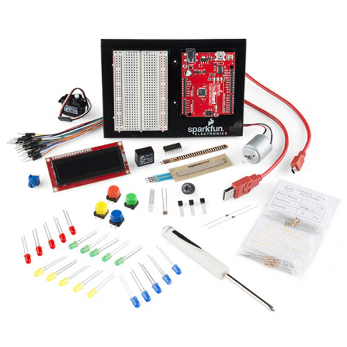
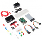
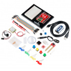
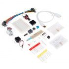
SparkFun Inventor’s Kit - V3.3
You should have one of the two following versions of the SIK. If you need a overview of the parts included in your kit, please click on the product link below.
Out of stock
KIT-13969
The SparkFun Inventor's Kit (SIK) is a great way to get started with programming and hardware interaction with the Arduino pr…
Out of stock
KIT-13970
The SparkFun Inventor's Kit (SIK) is a great way to get started with programming and hardware interaction with the Arduino pr…
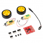
The primary difference between the two kits is the microcontroller included in the kit. The SparkFun Inventor’s Kit includes a SparkFun RedBoard, while the SparkFun Inventor’s Kit for Arduino Uno includes an Arduino Uno R3. At the heart of each is the ATmega328p microcontroller, giving both the same functionality underneath the hood. Both development boards are capable of taking inputs (such as the push of a button or a reading from a light sensor) and interpreting that information to control various outputs (like a blinking LED light or an electric motor). And much, much more!
Note: The Arduino Uno version of the kit
does not include a
carrying case or printed copy of this manual to decrease weight and cost for international shipping.
Note: You can complete all 16 experiments in this guide with either kit.
If you need more information to determine which microcontroller is right for you, please check out the following tutorials.
Open Source!
At SparkFun, our engineers and educators have been improving this kit and coming up with new experiments for a long time now. We would like to give attribution to Oomlout, since we originally started working off their Arduino Kit material many years ago. The Oomlut version is licensed under the Creative Commons Attribution Share-Alike 3.0 Unported License.
SparkFun’s version 3.3 is licensed under the Creative Commons Attribution Share-Alike International License.
Suggested Reading
Before continuing on with this tutorial, we recommend you be familiar with the concepts in the following tutorials:
How to Use a Breadboard
Welcome to the wonderful world of breadboards. Here we will learn what a breadboard is and how to use one to build your very first circuit.
Polarity
An introduction to polarity in electronic components. Discover what polarity is, which parts have it, and how to identify it.
What is a Circuit?
Every electrical project starts with a circuit. Don't know what a circuit is? We're here to help.
What is Electricity?
We can see electricity in action on our computers, lighting our houses, as lightning strikes in thunderstorms, but what is it? This is not an easy question, but this tutorial will shed some light on it!
Introduction: The Arduino Software (IDE) and Code
The following steps are a basic overview of getting started with the Arduino IDE. For more detailed, step-by-step instructions for setting up the Arduino IDE on your computer, please check out the following tutorial.
Installing Arduino IDE
A step-by-step guide to installing and testing the Arduino software on Windows, Mac, and Linux.
Download the Arduino IDE
In order to get your microcontroller up and running, you’ll need to download the newest version of the Arduino software first (it’s free and open source!).
Download the Arduino IDE
This software, known as the Arduino IDE, will allow you to program the board to do exactly what you want. It’s like a word processor for writing code.
Connect the Microcontroller to your Computer
Use the USB cable provided in the SIK kit to connect the included microcontroller (RedBoard or Arduino Uno) to one of your computer’s USB inputs.
Install FTDI Drivers
Depending on your computer’s operating system, you will need to follow specific instructions. Please go to How to Install FTDI Drivers, for specific instructions on how to install the FTDI drivers onto your RedBoard.
Select your board: Arduino Uno
Before we can start jumping into the experiments, there are a couple adjustments we need to make.
This step is required to tell the Arduino IDE which of the many Arduino boards we have. Go up to the Tools menu. Then hover over Board and make sure Arduino Uno is selected.
Please note: Your SparkFun RedBoard and the Arduino UNO are interchangeable but you won’t find the RedBoard listed in the Arduino Software. Select “Arduino Uno” instead.
Select a Serial Port
Next up we need to tell the Arduino IDE which of our computer’s serial ports the microcontroller is connected to. For this, again go up to Tools, then hover over Port (Serial Port in older Arduino versions) and select your RedBoard or Arduino’s serial port.
Download Arduino Code
You are so close to to being done with setup! Download the SIK Guide Code. Click the following link to download the code:
SIK V3.3 Code
You can also download the code from GitHub.
Once you’ve unzipped the download, copy SIK-Guide-Code-V_3.3 into examples folder in the Arduino folder.
Experiment 1: Blinking an LED
Introduction
LEDs are small, powerful lights that are used in many different applications. To start off, we will work on blinking an LED, the Hello World of microcontrollers. That’s right - it’s as simple as turning a light on and off. It might not seem like much, but establishing this important baseline will give you a solid foundation as we work toward more complex experiments.
Parts Needed
You will need the following parts:
Suggested Reading
Before continuing on with this experiment, we recommend you be familiar with the concepts in the following tutorial:
Hardware Hookup
Ready to start hooking everything up? Check out the Fritzing diagram and hookup table below, to see how everything is connected.
| Polarized Components | Pay special attention to the component’s markings indicating how to place it on the breadboard. Polarized components can only be connected to a circuit in one direction. |
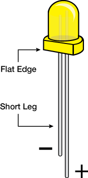
Please note: Pay close attention to the LED. The negative side of the LED is the short leg, marked with a flat edge.
![LED drawing]()
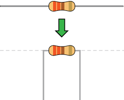
Components like resistors need to have their legs bent into 90° angles in order to correctly fit the breadboard sockets. You can also cut the legs shorter to make them easier to work with on the breadboard.
![Bent resistor]()
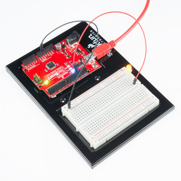
Fritzing Diagram for RedBoard
![alt text]()
Having a hard time seeing the circuit? Click on the Fritzing diagram to see a bigger image.
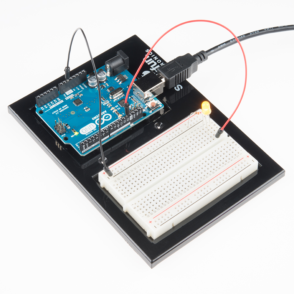
Fritzing Diagram for Arduino
![alt text]()
Having a hard time seeing the circuit? Click on the Fritzing diagram to see a bigger image.
Open Your First Sketch
Open Up the Arduino IDE software on your computer. Coding in the Arduino language will control your circuit. Open the code for Circuit 1 by accessing the SIK Guide Code you downloaded and placed into your examples folder earlier.
To open the code, go to: File > Examples > SIK Guide Code > SIK_circuit01_blink
![alt text]()
Click the picture above for a larger, easier-to-view image
Alternatively, you can copy and paste the following code into the Arduino IDE. Hit upload, and see what happens!
language:cpp
/* SparkFun Inventor's Kit
   Example sketch 01 -- BLINKING A LED

 Turn an LED on for one second, off for one second,
 and repeat forever.

 This sketch was written by SparkFun Electronics,
 with lots of help from the Arduino community.
 This code is completely free for any use.
 Visit http://www.sparkfun.com/sik for SIK information.
 Visit http://www.arduino.cc to learn about the Arduino.

 Version 2.0 6/2012 MDG
 */

void setup()
{
  pinMode(13, OUTPUT);
}

void loop()
{
  digitalWrite(13, HIGH);   // Turn on the LED
  delay(1000);              // Wait for one second
  digitalWrite(13, LOW);    // Turn off the LED
  delay(1000);              // Wait for one second
}
/*
 / Try changing the 1000 in the above delay() functions to
 / different numbers and see how it affects the timing. Smaller
 / values will make the loop run faster. (Why?)
 /
 / Other challenges:
 /   * Decrease the delay to 10 ms. Can you still see it blink?
 /         Find the smallest delay that you can still see a blink. What is this frequency?
 /   * Modify the code above to resemble a heartbeat.
 */
Code to Note
pinMode(13, OUTPUT);
Before you can use one of the Arduino’s pins, you need to tell the RedBoard or Arduino Uno R3 whether it is an INPUT or OUTPUT. We use a built-in “function” called pinMode() to do this.
digitalWrite(13, HIGH);
When you’re using a pin as an OUTPUT, you can command it to be HIGH (output 5 volts), or LOW (output 0 volts).
What You Should See
You should see your LED blink on and off. If it isn’t, make sure you have assembled the circuit correctly and verified and uploaded the code to your board, or see the troubleshooting section.
Real World Application
Almost all modern flat screen televisions and monitors have LED indicator lights to show they are on or off.
![alt text]()
Troubleshooting
LED Not Lighting Up?
LEDs will only work in one direction. Try taking it out of your breadboard, turning it 180 degrees, and reinserting it.
Program Not Uploading
This happens sometimes, the most likely cause is a confused serial port, you can change this in Tools > Serial Port >
Still No Success?
A broken circuit is no fun, send us an e-mail and we will get back to you as soon as we can: techsupport@sparkfun.com
Experiment 2: Reading a Potentiometer
Introduction
In this circuit you’ll work with a potentiometer.
A potentiometer is also known as a variable resistor. When powered with 5V, the middle pin outputs a voltage between 0V and 5V, depending on the position of the knob on the potentiometer. A potentiometer is a perfect demonstration of a variable voltage divider circuit. The voltage is divided proportionate to the resistance between the middle pin and the ground pin. In this circuit, you’ll learn how to use a potentiometer to control the brightness of an LED.
Parts Needed
You will need the following parts:
Suggested Reading
Before continuing on with this experiment, we recommend you be familiar with the concepts in the following tutorial:
Hardware Hookup
Ready to start hooking everything up? Check out the Fritzing diagram and hookup table below to see how everything is connected.
| Polarized Components | Pay special attention to the component’s markings indicating how to place it on the breadboard. Polarized components can only be connected to a circuit in one direction. |
Fritzing Diagram for RedBoard
![RedBoard Fritzing Potentiometer]()
Having a hard time seeing the circuit? Click on the Fritzing diagram to see a bigger image.
Fritzing Diagram for Arduino
![Arduino Uno Fritzing Potentiometer]()
Having a hard time seeing the circuit? Click on the Fritzing diagram to see a bigger image.
Open the Sketch
Open Up the Arduino IDE software on your computer. Coding in the Arduino language will control your circuit. Open the code for Circuit 2 by accessing the “SIK Guide Code” you downloaded and placed into your “Examples” folder earlier.
To open the code go to: File > examples > SIK Guide Code > SIK_circuit02_potentiometer
You can also copy and paste the following code into the Arduino IDE. Hit upload, and see what happens!
language:cpp
   /* SparkFun Inventor's Kit
 Example sketch 02 -- POTENTIOMETER

 Measure the position of a potentiometer and use it to
 control the blink rate of an LED. Turn the knob to make
 it blink faster or slower!

 This sketch was written by SparkFun Electronics,
 with lots of help from the Arduino community.
 This code is completely free for any use.
 Visit http://learn.sparkfun.com/products/2 for SIK information.
 Visit http://www.arduino.cc to learn about the Arduino.

 Version 2.0 6/2012 MDG
 */

int sensorPin = A0;    // The potentiometer is connected to analog pin 0
int ledPin = 13;      // The LED is connected to digital pin 13
int sensorValue;    //We declare another integer variable to store the value of the potentiometer

void setup() // this function runs once when the sketch starts up
{
  pinMode(ledPin, OUTPUT);
}

void loop() // this function runs repeatedly after setup() finishes
{
  sensorValue = analogRead(sensorPin);

  digitalWrite(ledPin, HIGH);     // Turn the LED on
  delay(sensorValue);             // Pause for sensorValue in milliseconds
  digitalWrite(ledPin, LOW);      // Turn the LED off
  delay(sensorValue);             // Pause for sensorValue in milliseconds
}
Code To Note
int sensorValue;
A “variable” is a placeholder for values that may change in your code. You must introduce, or “declare” variables before you use them; here we’re declaring a variable called sensorValue, of type “int” (integer). Don’t forget that variable names are case-sensitive!
sensorValue = analogRead(sensorPin);
We use the analogRead() function to read the value on an analog pin. analogRead() takes one parameter, the analog pin you want to use (“sensorPin”), and returns a number (“sensorValue”) between 0 (0 volts) and 1023 (5 volts).
delay(sensorValue);
Microcontrollers are very fast, capable of running thousands of lines of code each second. To slow it down so that we can see what it’s doing, we’ll often insert delays into the code. delay() counts in milliseconds; there are 1000 ms in one second.
What You Should See
You should see the LED blink faster or slower in accordance with your potentiometer. If it isn’t working, make sure you have assembled the circuit correctly and verified and uploaded the code to your board, or see the troubleshooting section.
Real World Application
Most traditional volume knobs employ a potentiometer.
Troubleshooting
Sporadically Working
This is most likely due to a slightly dodgy connection with the potentiometer’s pins. This can usually be conquered by holding the potentiometer down.
Not Working
Make sure you haven’t accidentally connected the wiper, the resistive element in the potentiometer, to digital pin 0 rather than analog pin 0. (the row of pins beneath the power pins).
LED Not Lighting Up?
LEDs will only work in one direction. Double check your connections.
Experiment 3: Driving an RGB LED
Introduction
You know what’s even more fun than a blinking LED? Changing colors with one LED. RGB, or red-green-blue, LEDs have three different color-emitting diodes that can be combined to create all sorts of colors. In this circuit, you’ll learn how to use an RGB LED to create unique color combinations. Depending on how bright each diode is, nearly any color is possible!
Parts Needed
You will need the following parts:
Hardware Hookup
Ready to start hooking everything up? Check out the Fritzing diagram and hookup table below, to see how everything is connected.
| Polarized Components | Pay special attention to the component’s markings indicating how to place it on the breadboard. Polarized components can only be connected to a circuit in one direction. |
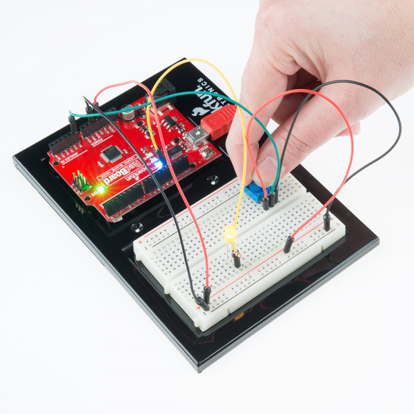
Fritzing Diagram for RedBoard
![RedBoard Circuit 3]()
Having a hard time seeing the circuit? Click on the Fritzing diagram to see a bigger image.
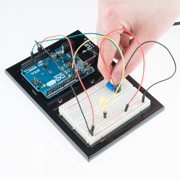
Fritzing Diagram for Arduino
![Arduino Circuit 3]()
Having a hard time seeing the circuit? Click on the Fritzing diagram to see a bigger image.
Open the Sketch
Open Up the Arduino IDE software on your computer. Coding in the Arduino language will control your circuit. Open the code for Circuit 3 by accessing the “SIK Guide Code” you downloaded and placed into your “Examples” folder earlier.
To open the code go to: File > examples > SIK Guide Code > SIK_circuit03_rgbLED
You can also copy and paste the following code into the Arduino IDE. Hit upload, and see what happens!
language:cpp
/******************************************************************
 * SparkFun Inventor's Kit
 * Example sketch 03 -- RGB LED
 *
 * Make an RGB LED display a rainbow of colors!
 *
 * This sketch was written by SparkFun Electronics,
 * with lots of help from the Arduino community.
 * Visit http://learn.sparkfun.com/products/2 for SIK information.
 * Visit http://www.arduino.cc to learn about the Arduino.
 *
 * Version 2.0 6/2012 MDG
 * Version 2.1 9/2014 BCH
 *****************************************************************/
const int RED_PIN = 9;
const int GREEN_PIN = 10;
const int BLUE_PIN = 11;

const int DISPLAY_TIME = 1000;  // used in mainColors() to determine the
// length of time each color is displayed.

void setup()    //Configure the Arduino pins to be outputs to drive the LEDs
{
  pinMode(RED_PIN, OUTPUT);
  pinMode(GREEN_PIN, OUTPUT);
  pinMode(BLUE_PIN, OUTPUT);
}

void loop()
{
  mainColors();        // Red, Green, Blue, Yellow, Cyan, Purple, White
  //  showSpectrum();    // Gradual fade from Red to Green to Blue to Red
}

/******************************************************************
 * void mainColors()
 * This function displays the eight "main" colors that the RGB LED
 * can produce. If you'd like to use one of these colors in your
 * own sketch, you can copy and paste that section into your code.
/*****************************************************************/
void mainColors()
{
  // all LEDs off
  digitalWrite(RED_PIN, LOW);
  digitalWrite(GREEN_PIN, LOW);
  digitalWrite(BLUE_PIN, LOW);
  delay(DISPLAY_TIME);

  // Red
  digitalWrite(RED_PIN, HIGH);
  digitalWrite(GREEN_PIN, LOW);
  digitalWrite(BLUE_PIN, LOW);
  delay(DISPLAY_TIME);

  // Green
  digitalWrite(RED_PIN, LOW);
  digitalWrite(GREEN_PIN, HIGH);
  digitalWrite(BLUE_PIN, LOW);
  delay(DISPLAY_TIME);

  // Blue
  digitalWrite(RED_PIN, LOW);
  digitalWrite(GREEN_PIN, LOW);
  digitalWrite(BLUE_PIN, HIGH);
  delay(DISPLAY_TIME);

  // Yellow (Red and Green)
  digitalWrite(RED_PIN, HIGH);
  digitalWrite(GREEN_PIN, HIGH);
  digitalWrite(BLUE_PIN, LOW);
  delay(DISPLAY_TIME);

  // Cyan (Green and Blue)
  digitalWrite(RED_PIN, LOW);
  digitalWrite(GREEN_PIN, HIGH);
  digitalWrite(BLUE_PIN, HIGH);
  delay(DISPLAY_TIME);

  // Purple (Red and Blue)
  digitalWrite(RED_PIN, HIGH);
  digitalWrite(GREEN_PIN, LOW);
  digitalWrite(BLUE_PIN, HIGH);
  delay(DISPLAY_TIME);

  // White (turn all the LEDs on)
  digitalWrite(RED_PIN, HIGH);
  digitalWrite(GREEN_PIN, HIGH);
  digitalWrite(BLUE_PIN, HIGH);
  delay(DISPLAY_TIME);
}

/******************************************************************
 * void showSpectrum()
 *
 * Steps through all the colors of the RGB LED, displaying a rainbow.
 * showSpectrum() calls a function RGB(int color) that translates a number
 * from 0 to 767 where 0 = all RED, 767 = all RED
 *
 * Breaking down tasks down into individual functions like this
 * makes your code easier to follow, and it allows.
 * parts of your code to be re-used.
/*****************************************************************/

void showSpectrum()
{
  for (int x = 0; x <= 767; x++)
  {
    RGB(x);      // Increment x and call RGB() to progress through colors.
    delay(10);   // Delay for 10 ms (1/100th of a second) - to help the "smoothing"
  }
}

/******************************************************************
 * void RGB(int color)
 *
 * RGB(###) displays a single color on the RGB LED.
 * Call RGB(###) with the number of a color you want
 * to display. For example, RGB(0) displays pure RED, RGB(255)
 * displays pure green.
 *
 * This function translates a number between 0 and 767 into a
 * specific color on the RGB LED. If you have this number count
 * through the whole range (0 to 767), the LED will smoothly
 * change color through the entire spectrum.
 *
 * The "base" numbers are:
 * 0   = pure red
 * 255 = pure green
 * 511 = pure blue
 * 767 = pure red (again)
 *
 * Numbers between the above colors will create blends. For
 * example, 640 is midway between 512 (pure blue) and 767
 * (pure red). It will give you a 50/50 mix of blue and red,
 * resulting in purple.
/*****************************************************************/
void RGB(int color)
{
  int redIntensity;
  int greenIntensity;
  int blueIntensity;

  color = constrain(color, 0, 767); // constrain the input value to a range of values from 0 to 767

    // if statement breaks down the "color" into three ranges:
  if (color <= 255)       // RANGE 1 (0 - 255) - red to green
  {
    redIntensity = 255 - color;    // red goes from on to off
    greenIntensity = color;        // green goes from off to on
    blueIntensity = 0;             // blue is always off
  }
  else if (color <= 511)  // RANGE 2 (256 - 511) - green to blue
  {
    redIntensity = 0;                     // red is always off
    greenIntensity = 511 - color;         // green on to off
    blueIntensity = color - 256;          // blue off to on
  }
  else                    // RANGE 3 ( >= 512)- blue to red
  {
    redIntensity = color - 512;         // red off to on
    greenIntensity = 0;                 // green is always off
    blueIntensity = 767 - color;        // blue on to off
  }

  // "send" intensity values to the Red, Green, Blue Pins using analogWrite()
  analogWrite(RED_PIN, redIntensity);
  analogWrite(GREEN_PIN, greenIntensity);
  analogWrite(BLUE_PIN, blueIntensity);
}
Code To Note
language:cpp
for (x = 0; x < 768; x++)
{}
A for() loop is used to repeat an action a set number of times across a range, and repeatedly runs code within the brackets {}. Here the variable “x” starts a 0, ends at 767, and increases by one each time (“x++”).
language:cpp
if (x <= 255)
{}
else
{}
“If / else” statements are used to make choices in your programs. The statement within the parenthesis () is evaluated; if it’s true, the code within the first brackets {} will run. If it’s not true, the code within the second brackets {} will run.
What You Should See
You should see your LED turn on, but this time in new, crazy colors! If it isn’t, make sure you have assembled the circuit correctly and verified and uploaded the code to your board or see the troubleshooting section.
Real World Application
Many electronics such as video game consoles use RGB LEDs to have the versatility to show different colors in the same area. Often times the different colors represent different states of working condition.
Troubleshooting
LED Remains Dark or Shows Incorrect Color
With the four pins of the LED so close together, it’s sometimes easy to misplace one. Double check each pin is where it should be.
Seeing Red
The red diode within the RGB LED may be a bit brighter than the other two. To make your colors more balanced, use a higher ohm resistor, or adjust in the code.
analogWrite(RED_PIN, redIntensity);
to
analogWrite(RED_PIN, redIntensity/3);
Experiment 4: Driving Multiple LEDs
Introduction
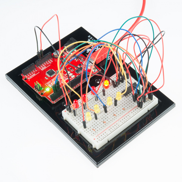
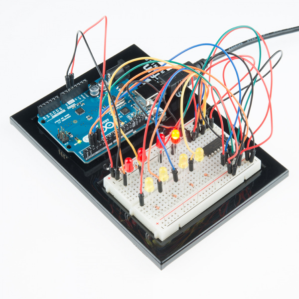
Now that you’ve gotten your LED to blink on and off, it’s time to up the stakes a little bit – by connecting eight LEDs at once. We’ll also give your RedBoard or Arduino R3 a little test by creating various lighting sequences. This circuit is a great setup to start practicing writing your own programs and getting a feel for the way Arduino works.
Along with controlling the LEDs, you’ll learn about a couple programming tricks that keep your code neat and tidy:
for() loops - used when you want to run a piece of code several times
arrays[ ] - used to make managing variables easier by grouping them together
Parts Needed
You will need the following parts:
Hardware Hookup
Ready to start hooking everything up? Check out the Fritzing diagram and hookup table below, to see how everything is connected.
| Polarized Components | Pay special attention to the component’s markings indicating how to place it on the breadboard. Polarized components can only be connected to a circuit in one direction. |
Fritzing Diagram for RedBoard
![alt text]()
Having a hard time seeing the circuit? Click on the Fritzing diagram to see a bigger image.
Fritzing Diagram for Arduino
![alt text]()
Having a hard time seeing the circuit? Click on the Fritzing diagram to see a bigger image.
Open the Sketch
Open Up the Arduino IDE software on your computer. Coding in the Arduino language will control your circuit. Open the code for Circuit 4 by accessing the “SIK Guide Code” you downloaded and placed into your “Examples” folder earlier.
To open the code go to: File > examples > SIK Guide Code > SIK_circuit04_multipleLEDs
You can also copy and paste the following code into the Arduino IDE. Hit upload, and see what happens!
language:cpp
/******************************************************************
 * SparkFun Inventor's Kit
 * Example sketch 04 -- MULTIPLE LEDs
 *
 *   Make eight LEDs dance. Dance LEDs, dance!
 * This sketch was written by SparkFun Electronics,
 * with lots of help from the Arduino community.
 * Visit http://learn.sparkfun.com/products/2 for SIK information.
 * Visit http://www.arduino.cc to learn about the Arduino.
 *
 * Version 2.0 6/2012 MDG
 * Version 2.1 9/2014 BCH
/*****************************************************************/

int ledPins[] = {2,3,4,5,6,7,8,9};   // Defines an array to store the pin numbers of the 8 LEDs.
// An array is like a list variable that can store multiple numbers.
// Arrays are referenced or "indexed" with a number in the brackets [ ]. See the examples in
// the pinMode() functions below.

void setup()
{
  // setup all 8 pins as OUTPUT - notice that the list is "indexed" with a base of 0.
  pinMode(ledPins[0],OUTPUT);  // ledPins[0] = 2
  pinMode(ledPins[1],OUTPUT);  // ledPins[1] = 3
  pinMode(ledPins[2],OUTPUT);  // ledPins[2] = 4
  pinMode(ledPins[3],OUTPUT);  // ledPins[3] = 5
  pinMode(ledPins[4],OUTPUT);  // ledPins[4] = 6
  pinMode(ledPins[5],OUTPUT);  // ledPins[5] = 7
  pinMode(ledPins[6],OUTPUT);  // ledPins[6] = 8
  pinMode(ledPins[7],OUTPUT);  // ledPins[7] = 9
}

void loop()
{

  // This loop() calls functions that we've written further below.
  // We've disabled some of these by commenting them out (putting
  // "//" in front of them). To try different LED displays, remove
  // the "//" in front of the ones you'd like to run, and add "//"
  // in front of those you don't to comment out (and disable) those
  // lines.

  oneAfterAnother();  // Light up all the LEDs in turn

  //oneOnAtATime();         // Turn on one LED at a time,

  //pingPong();             // Light the LEDs middle to the edges

  //marquee();              // Chase lights like you see on signs

  //randomLED();            // Blink LEDs randomly
}


/******************************************************************
 * oneAfterAnother()
 *
 * This function turns all the LEDs on, pauses, and then turns all
 * the LEDS off. The function takes advantage of for() loops and
 * the array to do this with minimal typing.
/*****************************************************************/
void oneAfterAnother()
{
  int index;
  int delayTime = 100; // milliseconds to pause between LEDs
                       // make this smaller for faster switching

  // Turn all the LEDs on:
  for(index = 0; index <= 7; index = index++)  // step through index from 0 to 7
  {
    digitalWrite(ledPins[index], HIGH);
    delay(delayTime);
  }

  // Turn all the LEDs off:
  for(index = 7; index >= 0; index = index--)  // step through index from 7 to 0
  {
    digitalWrite(ledPins[index], LOW);
    delay(delayTime);
  }
}

/*****************************************************************
 * oneOnAtATime()
 *
 * This function will step through the LEDs, lighting only one at
 * a time. It turns each LED ON and then OFF before going to the
 * next LED.
/****************************************************************/

void oneOnAtATime()
{
  int index;
  int delayTime = 100; // milliseconds to pause between LEDs
                       // make this smaller for faster switching

  for(index = 0; index <= 7; index = index ++)   // step through the LEDs, from 0 to 7
  {
    digitalWrite(ledPins[index], HIGH);  // turn LED on
    delay(delayTime);                    // pause to slow down
    digitalWrite(ledPins[index], LOW);   // turn LED off
  }

  for(index = 7; index >= 0; index = index --)   // step through the LEDs, from 7 to 0
  {
    digitalWrite(ledPins[index], HIGH);  // turn LED on
    delay(delayTime);                    // pause to slow down
    digitalWrite(ledPins[index], LOW);   // turn LED off
  }
}


/*****************************************************************
 * pingPong()
 *
 * This function will step through the LEDs, lighting one at at
 * time in both directions. There is no delay between the LED off
 * and turning on the next LED. This creates a smooth pattern for
 * the LED pattern.
/****************************************************************/
void pingPong()
{
  int index;
  int delayTime = 100; // milliseconds to pause between LEDs

  for(index = 0; index <= 7; index = index ++)   // step through the LEDs, from 0 to 7
  {
    digitalWrite(ledPins[index], HIGH);  // turn LED on
    delay(delayTime);                    // pause to slow down
    digitalWrite(ledPins[index], LOW);   // turn LED off
  }

  for(index = 7; index >= 0; index = index --)   // step through the LEDs, from 7 to 0
  {
    digitalWrite(ledPins[index], HIGH);  // turn LED on
    delay(delayTime);                    // pause to slow down
    digitalWrite(ledPins[index], LOW);   // turn LED off
  }
}

/*****************************************************************
 * marquee()
 *
 * This function will mimic "chase lights" like those around signs.
/****************************************************************/
void marquee()
{
  int index;
  int delayTime = 200; // milliseconds to pause between LEDs

  // Step through the first four LEDs
  // (We'll light up one in the lower 4 and one in the upper 4)

  for(index = 0; index <= 3; index++) // Step from 0 to 3
  {
    digitalWrite(ledPins[index], HIGH);    // Turn a LED on
    digitalWrite(ledPins[index+4], HIGH);  // Skip four, and turn that LED on
    delay(delayTime);                      // Pause to slow down the sequence
    digitalWrite(ledPins[index], LOW);     // Turn the LED off
    digitalWrite(ledPins[index+4], LOW);   // Skip four, and turn that LED off
  }
}

/*****************************************************************
 * randomLED()
 *
 * This function will turn on random LEDs. Can you modify it so it
 * also lights them for random times?
/****************************************************************/
void randomLED()
{
  int index;
  int delayTime;

  index = random(8);    // pick a random number between 0 and 7
  delayTime = 100;

  digitalWrite(ledPins[index], HIGH);  // turn LED on
  delay(delayTime);                    // pause to slow down
  digitalWrite(ledPins[index], LOW);   // turn LED off
}
Code To Note
int ledPins[] = {2,3,4,5,6,7,8,9};
When you have to manage a lot of variables, an “array” is a handy way to group them together. Here we’re creating an array of integers, called ledPins, with eight elements.
digitalWrite(ledPins[0], HIGH);
You refer to the elements in an array by their position. The first element is at position 0, the second is at position 1, etc. You refer to an element using “ledPins[x]” where x is the position. Here we’re making digital pin 2 HIGH, since the array element at position 0 is “2”.
index = random(8);
Computers like to do the same things each time they run. But sometimes you want to do things randomly, such as simulating the roll of a dice. The random() function is a great way to do this.
See http://arduino.cc/en/reference/random for more information.
What You Should See
This is similar to circuit number one, but instead of one LED, you should see all the LEDs blink. If they aren’t, make sure you have assembled the circuit correctly and verified and uploaded the code to your board, or see the troubleshooting section.
Real World Application
Scrolling marquee displays are generally used to spread short segments of important information. They are built out of many LEDs.
Troubleshooting
Some LEDs Fail to Light
It is easy to insert an LED backwards. Check the LEDs that aren’t working and ensure they are in the correct orientation.
Operating out of sequence
With eight wires it’s easy to cross a couple. Double check that the first LED is plugged into pin 2 and each pin thereafter.
Starting Fresh
It’s easy to accidentally misplace a wire without noticing. Pulling everything out and starting with a fresh slate is often easier than trying to track down the problem.
Introduction
Up until now, we’ve focused mostly on outputs. Now we’re going to go to the other end of spectrum and play around with inputs. In experiment 2, we used an analog input to read the potentiometer. In this circuit, we’ll be reading in one of the most common and simple inputs – a push button – by using a digital input. The way a push button works with your RedBoard or Arduino Uno R3 is that when the button is pushed, the voltage goes LOW. Your RedBoard or Arduino Uno R3 reads this and reacts accordingly.
In this circuit, you will also use a pull-up resistor, which keeps the voltage HIGH when you’re not pressing the button.
Parts Needed
You will need the following parts:
Suggested Reading
Before continuing on with this tutorial, we recommend you be somewhat familiar with the concepts in these tutorials:
Hardware Hookup
Ready to start hooking everything up? Check out the Fritzing diagram and hookup table below, to see how everything is connected.
| Polarized Components | Pay special attention to the component’s markings indicating how to place it on the breadboard. Polarized components can only be connected to a circuit in one direction. |
Fritzing Diagram for RedBoard
![alt text]()
Having a hard time seeing the circuit? Click on the Fritzing diagram to see a bigger image.
Fritzing Diagram for Arduino
![alt text]()
Having a hard time seeing the circuit? Click on the Fritzing diagram to see a bigger image.
Open the Sketch
Open Up the Arduino IDE software on your computer. Coding in the Arduino language will control your circuit. Open the code for Circuit 5 by accessing the “SIK Guide Code” you downloaded and placed into your “Examples” folder earlier.
To open the code go to: File > examples > SIK Guide Code > SIK_circuit05_pushButton
You can also copy and paste the following code into the Arduino IDE. Hit upload, and see what happens!
language:cpp
/******************************************************************
 * SparkFun Inventor's Kit
 * Example sketch 05 -- PUSH BUTTONS
 *
 *   Use pushbuttons for digital input
 *
 *   Connect one side of the pushbutton to GND, and the other
 *   side to a digital pin. When we press down on the pushbutton,
 *   the pin will be connected to GND, and therefore will be read
 *   as "LOW" by the Arduino.
 *
 * This sketch was written by SparkFun Electronics,
 * with lots of help from the Arduino community.
 * This code is completely free for any use.
 * Visit http://learn.sparkfun.com/products/2 for SIK information.
 * Visit http://www.arduino.cc to learn about the Arduino.
 *
 * Version 2.0 6/2012 MDG
 * Version 2.1 9/2014 BCH
/*****************************************************************/

const int button1Pin = 2;  // pushbutton 1 pin
const int button2Pin = 3;  // pushbutton 2 pin
const int ledPin =  13;    // LED pin

int button1State, button2State;  // variables to hold the pushbutton states


void setup()
{
  // Set up the pushbutton pins to be an input:
  pinMode(button1Pin, INPUT);
  pinMode(button2Pin, INPUT);

  // Set up the LED pin to be an output:
  pinMode(ledPin, OUTPUT);
}

void loop()
{
  button1State = digitalRead(button1Pin);
  button2State = digitalRead(button2Pin);

  // if button1 or button 2 are pressed (but not both)
  if (((button1State == LOW) && (button2State == HIGH)) || ((button1State == HIGH) && (button2State == LOW)))
  {
    digitalWrite(ledPin, HIGH);  // turn the LED on
  }
  else
  {
    digitalWrite(ledPin, LOW);  // turn the LED off
  }
}
Code To Note
pinMode(button2Pin, INPUT);
The digital pins can be used as inputs as well as outputs. Before you do either, you need to tell the Arduino which direction you’re going.
button1State = digitalRead(button1Pin);
To read a digital input, you use the digitalRead() function. It will return HIGH if there’s 5V present at the pin, or LOW if there’s 0V present at the pin.
if (button1State == LOW)
Because we’ve connected the button to GND, it will read LOW when it’s being pressed. Here we’re using the “equivalence” operator (“==”) to see if the button is being pressed.
What You Should See
You should see the LED turn on if you press either button, and off if you press both buttons. (See the code to find out why!) If it isn’t working, make sure you have assembled the circuit correctly and verified and uploaded the code to your board or see the troubleshooting section.
Real World Application
The buttons we used here are similar to the buttons in most video game controllers.
Troubleshooting
Light Not Turning On
The pushbutton is square, and because of this it is easy to put it in the wrong way. Give it a 90 degree twist and see if it starts working.
Underwhelmed
No worries, these circuits are all super stripped down to make playing with the components easy, but once you throw them together the sky is the limit.
Experiment 6: Reading a Photoresistor
Introduction
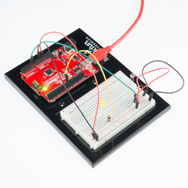
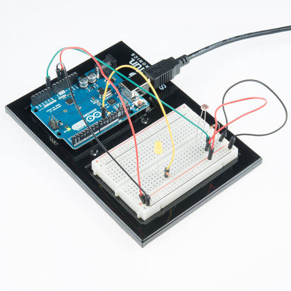
In experiment 2, you got to use a potentiometer, which varies resistance based on the twisting of a knob. In this circuit, you’ll be using a photoresistor, which changes resistance based on how much light the sensor receives. Since the RedBoard and Arduino Uno R3 can’t directly interpret resistance (rather, it reads voltage), we need to use a voltage divider to use our photoresistor. This voltage divider will output a high voltage when it is getting a lot of light and a low voltage when little or no light is present.
Parts Needed
You will need the following parts:
Hardware Hookup
Ready to start hooking everything up? Check out the Fritzing diagram below, to see how everything is connected.
| Polarized Components | Pay special attention to the component’s markings indicating how to place it on the breadboard. Polarized components can only be connected to a circuit in one direction. |
Fritzing Diagram for RedBoard
![alt text]()
Having a hard time seeing the circuit? Click on the Fritzing diagram to see a bigger image.
Fritzing Diagram for Arduino
![alt text]()
Having a hard time seeing the circuit? Click on the Fritzing diagram to see a bigger image.
Open the Sketch
Open Up the Arduino IDE software on your computer. Coding in the Arduino language will control your circuit. Open the code for Circuit 06 by accessing the “SIK Guide Code” you downloaded and placed into your “Examples” folder earlier.
To open the code go to: File > examples > SIK Guide Code > SIK_circuit06_photoResistor
You can also copy and paste the following code into the Arduino IDE. Hit upload, and see what happens!
language:cpp
/******************************************************************
 * SparkFun Inventor's Kit
 * Example sketch 06
 *
 * PHOTO RESISTOR
 *
 * Use a photoresistor (light sensor) to control the brightness
 * of a LED.
 *
 * This sketch was written by SparkFun Electronics,
 * with lots of help from the Arduino community.
 * This code is completely free for any use.
 * Visit http://learn.sparkfun.com/products/2 for SIK information.
 * Visit http://www.arduino.cc to learn about the Arduino.
 *
 * Version 2.0 6/2012 MDG
 * Version 2.1 9/2014 BCH
/*****************************************************************/

// As usual, we'll create constants to name the pins we're using.
// This will make it easier to follow the code below.

const int sensorPin = 0;
const int ledPin = 9;

// We'll also set up some global variables for the light level:
int lightLevel;
int calibratedlightLevel; // used to store the scaled / calibrated lightLevel
int maxThreshold = 0;     // used for setting the "max" light level
int minThreshold = 1023;   // used for setting the "min" light level

void setup()
{
  pinMode(ledPin, OUTPUT);    // Set up the LED pin to be an output.
  Serial.begin(9600);
}

void loop()
{
  lightLevel = analogRead(sensorPin);  // reads the voltage on the sensorPin
  Serial.print(lightLevel);
  //autoRange();  // autoRanges the min / max values you see in your room.

  calibratedlightLevel = map(lightLevel, 0, 1023, 0, 255);  // scale the lightLevel from 0 - 1023 range to 0 - 255 range.
                                                  // the map() function applies a linear scale / offset.
                                                  // map(inputValue, fromMin, fromMax, toMin, toMax);
  Serial.print("\t");         // tab character
  Serial.print(calibratedlightLevel);   // println prints an CRLF at the end (creates a new line after)

  analogWrite(ledPin, calibratedlightLevel);    // set the led level based on the input lightLevel.
}
/******************************************************************
 * void autoRange()
 *
 * This function sets a minThreshold and maxThreshold value for the
 * light levels in your setting. Move your hand / light source / etc
 * so that your light sensor sees a full range of values. This will
 * "autoCalibrate" to your range of input values.
/*****************************************************************/

void autoRange()
{
  if (lightLevel < minThreshold)  // minThreshold was initialized to 1023 -- so, if it's less, reset the threshold level.
    minThreshold = lightLevel;

  if (lightLevel > maxThreshold)  // maxThreshold was initialized to 0 -- so, if it's bigger, reset the threshold level.
    maxThreshold = lightLevel;

  // Once we have the highest and lowest values, we can stick them
  // directly into the map() function.
  //
  // This function must run a few times to get a good range of bright and dark values in order to work.

  lightLevel = map(lightLevel, minThreshold, maxThreshold, 0, 255);
  lightLevel = constrain(lightLevel, 0, 255);
}
Code To Note
lightLevel = map(lightLevel, 0, 1023, 0, 255);
Parameters
map(value, fromLow, fromHigh, toLow, toHigh)
value: the number to map
fromLow: the lower bound of the value’s current range
fromHigh: the upper bound of the value’s current range
toLow: the lower bound of the value’s target range
toHigh: the upper bound of the value’s target range
When we read an analog signal using analogRead(), it will be a number from 0 to 1023. But when we want to drive a PWM pin using analogWrite(), it wants a number from 0 to 255. We can “squeeze” the larger range into the smaller range using the map() function.
See Arduino’s map reference page for more info.
lightLevel = constrain(lightLevel, 0, 255);
Parameters
constrain(x, a, b)
x: the number to constrain, all data types
a: the lower end of the range, all data types
b: the upper end of the range, all data types
Because map() could still return numbers outside the “to” range, we’ll also use a function called constrain() that will “clip” numbers into a range. If the number is outside the range, it will make it the largest or smallest number. If it is within the range, it will stay the same.
See Arduino’s constrain reference page for more info.
What You Should See
You should see the LED grow brighter or dimmer in accordance with how much light your photoresistor is reading. If it isn’t working, make sure you have assembled the circuit correctly and verified and uploaded the code to your board or see the troubleshooting section.
Real World Application
Some street lamps as well as solar walkway lights use photoresistors to detect the absence of the sun and turn on the lights.
Troubleshooting
LED Remains Dark
This is a mistake we continue to make time and time again, if only they could make an LED that worked both ways. Pull it out of the breadboard, and reinsert it turned 180 degrees.
It Isn’t Responding to Changes in Light
Given that the spacing of the wires on the photoresistor is not standard, it is easy to misplace it. Double check it’s in the right place.
Still Not Quite Working
You may be in a room which is either too bright or dark. Try turning the lights on or off to see if this helps. Or if you have a flashlight near by give that a try.
Experiment 7: Reading a Temperature Sensor
Introduction
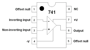
A temperature sensor is exactly what it sounds like – a sensor used to measure ambient temperature. This particular sensor has three pins – a positive, a ground, and a signal. This is a linear temperature sensor. A change in temperature of one degree centigrade is equal to a change of 10 millivolts at the sensor output.
The TMP36 sensor has a nominal 750 mV at 25°C (about room temperature). In this circuit, you’ll learn how to integrate the temperature sensor with your RedBoard or Arduino Uno R3, and use the Arduino IDE’s serial monitor to display the temperature.
Parts Needed
You will need the following parts:
Hardware Hookup
Ready to start hooking everything up? Check out the Fritzing diagram below, to see how everything is connected.
| Polarized Components | Pay special attention to the component’s markings indicating how to place it on the breadboard. Polarized components can only be connected to a circuit in one direction. |
Please note: The temperature sensor can only be connected to a circuit in one direction. See below for the pin outs of the temperature sensor - TMP36
![Temperature Sensor]()
Fritzing Diagram for RedBoard
![RedBoard Circuit 7]()
Having a hard time seeing the circuit? Click on the Fritzing diagram to see a bigger image.
Fritzing Diagram for Arduino
![Arduino Circuit 7]()
Having a hard time seeing the circuit? Click on the Fritzing diagram to see a bigger image.
Open the Sketch
Open Up the Arduino IDE software on your computer. Coding in the Arduino language will control your circuit. Open the code for Circuit 7 by accessing the “SIK Guide Code” you downloaded and placed into your “Examples” folder earlier.
To open the code go to: File > examples > SIK Guide Code > SIK_circuit07_tempSensor
You can also copy and paste the following code into the Arduino IDE. Hit upload, and see what happens!
language:cpp
/******************************************************************
 SparkFun Inventor's Kit
 Example sketch 07 - TEMPERATURE SENSOR
  Use the "serial monitor" window to read a temperature sensor.
  The TMP36 is an easy-to-use temperature sensor that outputs
  a voltage that's proportional to the ambient temperature.
  You can use it for all kinds of automation tasks where you'd
  like to know or control the temperature of something.
  More information on the sensor is available in the datasheet:
  http://dlnmh9ip6v2uc.cloudfront.net/datasheets/Sensors/Temp/TMP35_36_37.pdf
  Even more exciting, we'll start using the Arduino's serial port
  to send data back to your main computer! Up until now, we've
  been limited to using simple LEDs for output. We'll see that
  the Arduino can also easily output all kinds of text and data.
This sketch was written by SparkFun Electronics,
with lots of help from the Arduino community.
This code is completely free for any use.
Visit http://learn.sparkfun.com/products/2 for SIK information.
Visit http://www.arduino.cc to learn about the Arduino.
Version 2.0 6/2012 MDG
******************************************************************/


// We'll use analog input 0 to measure the temperature sensor's
// signal pin.

const int temperaturePin = A0;


void setup()
{

    Serial.begin(9600); //Initialize serial port & set baud rate to 9600 bits per second (bps)
}


void loop()
{


    float voltage, degreesC, degreesF; //Declare 3 floating point variables

    voltage = getVoltage(temperaturePin); //Measure the voltage at the analog pin

    degreesC = (voltage - 0.5) * 100.0; // Convert the voltage to degrees Celsius

    degreesF = degreesC * (9.0 / 5.0) + 32.0; //Convert degrees Celsius to Fahrenheit

    //Now print to the Serial monitor. Remember the baud must be 9600 on your monitor!
    // These statements will print lines of data like this:
    // "voltage: 0.73 deg C: 22.75 deg F: 72.96"

    Serial.print("voltage: ");
    Serial.print(voltage);
    Serial.print("  deg C: ");
    Serial.print(degreesC);
    Serial.print("  deg F: ");
    Serial.println(degreesF);

    delay(1000); // repeat once per second (change as you wish!)
}


float getVoltage(int pin)   //Function to read and return
                            //floating-point value (true voltage)
                            //on analog pin
{

    return (analogRead(pin) * 0.004882814);
    // This equation converts the 0 to 1023 value that analogRead()
    // returns, into a 0.0 to 5.0 value that is the true voltage
    // being read at that pin.
}

// Other things to try with this code:

//   Turn on an LED if the temperature is above or below a value.

//   Read that threshold value from a potentiometer - now you've
//   created a thermostat!
Code To Note
Serial.begin(9600);
Before using the serial monitor, you must call Serial.begin() to initialize it. 9600 is the “baud rate”, or communications speed. When two devices are communicating with each other, both must be set to the same speed.
Serial.print(degreesC);
The Serial.print() command is very smart. It can print out almost anything you can throw at it on the same line. This can include variables of all types, quoted text (AKA “strings”), etc.
See http://arduino.cc/en/serial/print for more info.
Serial.println(degreesF);
The Serial.println() has the same functionality except any serial data being printed after this command will start on the next line. By using both of these commands together, you can create easy-to-read printouts of text and data.
What You Should See
You should be able to read the temperature your temperature sensor is detecting on the serial monitor in the Arduino IDE. If it isn’t working, make sure you have assembled the circuit correctly and verified and uploaded the code to your board or see the troubleshooting section.
Example of what you should see in the Arduino IDE’s serial monitor:
voltage: 0.73 deg C: 23.24 deg F: 73.84
voltage: 0.73 deg C: 23.24 deg F: 73.84
voltage: 0.73 deg C: 22.75 deg F: 72.96
voltage: 0.73 deg C: 23.24 deg F: 73.84
voltage: 0.73 deg C: 23.24 deg F: 73.84
voltage: 0.73 deg C: 23.24 deg F: 73.84
voltage: 0.73 deg C: 22.75 deg F: 72.96
voltage: 0.73 deg C: 23.24 deg F: 73.84
voltage: 0.73 deg C: 22.75 deg F: 72.96
voltage: 0.73 deg C: 22.75 deg F: 72.96
voltage: 0.73 deg C: 23.24 deg F: 73.84
voltage: 0.73 deg C: 22.75 deg F: 72.96
voltage: 0.73 deg C: 23.24 deg F: 73.84
Real World Application
Building climate control systems use a temperature sensor to monitor and maintain their settings.
Troubleshooting
Nothing Seems to Happen
This program has no outward indication it is working. To see the results you must open the Arduino IDE’s serial monitor (instructions on previous page).
Gibberish is Displayed
This happens because the serial monitor is receiving data at a different speed than expected. To fix this, click the pull-down box that reads *** baud and change it to 9600 baud.
Temperature Value is Unchanging
Try pinching the sensor with your fingers to heat it up or pressing a bag of ice against it to cool it down. Also, make sure that the wires are connected properly to the temperature sensor.
Warm to the Touch
Make sure that you wired the temperature sensor correctly. The temperature sensor can get warm to the touch if it is wired incorrectly. You would need to disconnect your microcontroller, rewire the circuit, connect it back to your computer, and open the serial monitor.
Experiment 8: Driving a Servo Motor
Introduction
Servos are ideal for embedded electronics applications because they do one thing very well that motors cannot – they can move to a position accurately. By varying the pulse width of the output voltage to a servo, you can move a servo to a specific position. For example, a pulse of 1.5 milliseconds will move the servo 90 degrees. In this circuit, you’ll learn how to use PWM (pulse width modulation) to control and rotate a servo.
Parts Needed
You will need the following parts:
Suggested Reading
Before continuing on with this experiment, we recommend you be familiar with the concepts in the following tutorial:
Hardware Hookup
Ready to start hooking everything up? Check out the Fritzing diagram below, to see how everything is connected.
| Polarized Components | Pay special attention to the component’s markings indicating how to place it on the breadboard. Polarized components can only be connected to a circuit in one direction. |
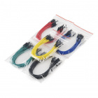
Connect 3x jumper wires to the female 3 pin header on the servo. This will make it easier to breadboard the servo.
![Servo Jumpers]()
Fritzing Diagram for RedBoard
![alt text]()
Having a hard time seeing the circuit? Click on the Fritzing diagram to see a bigger image.
Fritzing Diagram for Arduino
![alt text]()
Having a hard time seeing the circuit? Click on the Fritzing diagram to see a bigger image.
Open the Sketch
Open Up the Arduino IDE software on your computer. Coding in the Arduino language will control your circuit. Open the code for Circuit 08 by accessing the “SIK Guide Code” you downloaded and placed into your “Examples” folder earlier.
To open the code go to: File > examples > SIK Guide Code > SIK_circuit08-1_servoSweep
You can also copy and paste the following code into the Arduino IDE. Hit upload, and see what happens!
language:cpp
/*
SparkFun Inventor's Kit
Example sketch 08-1
SINGLE SERVO
  Sweep a servo back and forth through its full range of motion.
  A "servo", short for servomotor, is a motor that includes
  feedback circuitry that allows it to be commanded to move to
  specific positions. This one is very small, but larger servos
  are used extensively in robotics to control mechanical arms,
  hands, etc. You could use it to make a (tiny) robot arm,
  aircraft control surface, or anywhere something needs to be
  moved to specific positions.
This sketch was written by SparkFun Electronics,
with lots of help from the Arduino community.
This code is completely free for any use.
Visit http://learn.sparkfun.com/products/2 for SIK information.
Visit http://www.arduino.cc to learn about the Arduino.
Version 2.0 6/2012 MDG
*/


#include <Servo.h>  // servo library


Servo servo1;  // servo control object


void setup()
{

  servo1.attach(9, 900, 2100);  //Connect the servo to pin 9
                                //with a minimum pulse width of
                                //900 and a maximum pulse width of
                                //2100.

}


void loop()
{
  int position;

  // To control a servo, you give it the angle you'd like it
  // to turn to. Servos cannot turn a full 360 degrees, but you
  // can tell it to move anywhere between 0 and 180 degrees.

  // Change position at full speed:

  servo1.write(90);    // Tell servo to go to 90 degrees

  delay(1000);         // Pause to get it time to move

  servo1.write(180);   // Tell servo to go to 180 degrees

  delay(1000);         // Pause to get it time to move

  servo1.write(0);     // Tell servo to go to 0 degrees

  delay(1000);         // Pause to get it time to move


    // Tell servo to go to 180 degrees, stepping by two degrees each step

  for(position = 0; position < 180; position += 2)
  {
    servo1.write(position);  // Move to next position
    delay(20);               // Short pause to allow it to move
  }

  // Tell servo to go to 0 degrees, stepping by one degree each step

  for(position = 180; position >= 0; position -= 1)
  {
    servo1.write(position);  // Move to next position
    delay(20);               // Short pause to allow it to move
  }
}
Code To Note
#include <Servo.h>
#include is a special “preprocessor” command that inserts a library (or any other file) into your sketch. You can type this command yourself, or choose an installed library from the “sketch / import library” menu.
Servo servo1;
servo1.attach(9);
The servo library adds new commands that let you control a servo. To prepare the Arduino to control a servo, you must first create a Servo “object” for each servo (here we’ve named it “servo1”), and then “attach” it to a digital pin (here we’re using pin 9).
servo1.write(180);
The servos in this kit don’t spin all the way around, but they can be commanded to move to a specific position. We use the servo library’s write() command to move a servo to a specified number of degrees(0 to 180). Remember that the servo requires time to move, so give it a short delay() if necessary.
What You Should See
You should see your servo motor move to various locations at several speeds. If the motor doesn’t move, check your connections and make sure you have verified and uploaded the code, or see the troubleshooting section.
Real World Application
Robotic arms you might see in an assembly line or sci-fi movie probably have servos in them.
Troubleshooting
Servo Not Twisting
Even with colored wires it is still shockingly easy to plug a servo in backward. This might be the case.
Still Not Working
A mistake we made a time or two was simply forgetting to connect the power (red and black wires) to +5 volts and ground.
Fits and Starts
If the servo begins moving then twitches, and there’s a flashing light on your RedBoard or Arduino Uno R3, the power supply you are using is not quite up to the challenge. Using a wall adapter instead of USB should solve this problem.
More Servo Fun!
Now that you know the basics of working with servos, try to figure out how to make your servo move using the following code.
To open the code go to: File > examples > SIK Guide Code > SIK_circuit08-2_serialServo
You can also copy and paste the following code into the Arduino IDE. Hit upload, and see what happens!
language:c
    /*
SparkFun Inventor's Kit
Example sketch 08-2
SINGLE SERVO
  Sweep a servo back and forth through its full range of motion.
  A "servo", short for servomotor, is a motor that includes
  feedback circuitry that allows it to be commanded to move to
  specific positions. This one is very small, but larger servos
  are used extensively in robotics to control mechanical arms,
  hands, etc. You could use it to make a (tiny) robot arm,
  aircraft control surface, or anywhere something needs to be
  moved to specific positions.
This sketch was written by SparkFun Electronics,
with lots of help from the Arduino community.
This code is completely free for any use.
Visit http://learn.sparkfun.com/products/2 for SIK information.
Visit http://www.arduino.cc to learn about the Arduino.
Version 2.0 6/2012 MDG
*/


#include <Servo.h>  // servo library

Servo servo1;  // servo control object

int angle;

void setup()
{
  servo1.attach(9, 900, 2100);
  Serial.begin(9600);
}


void loop()
{
  serialServo();
}


void serialServo()
{
  int speed;

  Serial.println("Type an angle (0-180) into the box above,");
  Serial.println("then click [send] or press [return]");
  Serial.println();  // Print a blank line

  // In order to type out the above message only once,
  // we'll run the rest of this function in an infinite loop:

  while(true)  // "true" is always true, so this will loop forever.
  {
    // First we check to see if incoming data is available:

    while (Serial.available() > 0)
    {
      // If it is, we'll use parseInt() to pull out any numbers:
      angle = Serial.parseInt();

      // Because servo.write() only works with numbers from
      // 0 to 180, we'll be sure the input is in that range:

      angle = constrain(angle, 0, 180);

      // We'll print out a message to let you know that the
      // number was received:

      Serial.print("Setting angle to ");
      Serial.println(angle);

      // And finally, we'll move the servo to its new position!

      servo1.write(angle);
    }
  }
}
Hint: if you don’t see any servo movement, try reading the comments in the code!
Experiment 9: Using a Flex Sensor
Introduction
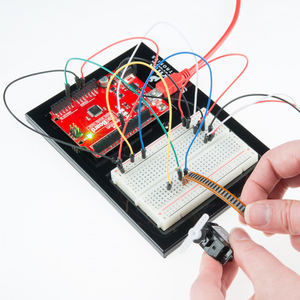
In this circuit, we will use a flex sensor to measure, well, flex! A flex sensor uses carbon on a strip of plastic to act like a variable resistor, but instead of changing the resistance by turning a knob, you change it by flexing (bending) the component. We use a “voltage divider” again to detect this change in resistance.
The sensor bends in one direction and the more it bends, the higher the resistance gets; it has a range from about 10K ohm to 35K ohm. In this circuit we will use the amount of bend of the flex sensor to control the position of a servo.
Parts Needed
You will need the following parts:
Suggested Reading
Before continuing on with this experiment, we recommend you be familiar with the concepts in the following tutorial:
Hardware Hookup
Ready to start hooking everything up? Check out the Fritzing diagram below, to see how everything is connected.
| Polarized Components | Pay special attention to the component’s markings indicating how to place it on the breadboard. Polarized components can only be connected to a circuit in one direction. |
Connect 3x jumper wires to the female 3 pin header on the servo. This will make it easier to breadboard the servo.
Fritzing Diagram for RedBoard
![RedBoard Circuit 9]()
Having a hard time seeing the circuit? Click on the Fritzing diagram to see a bigger image.
Fritzing Diagram for Arduino
![Arduino Circuit 9]()
Having a hard time seeing the circuit? Click on the Fritzing diagram to see a bigger image.
Open the Sketch
Open Up the Arduino IDE software on your computer. Coding in the Arduino language will control your circuit. Open the code for Circuit 9 by accessing the “SIK Guide Code” you downloaded and placed into your “Examples” folder earlier.
To open the code go to: File > Examples > SIK Guide Code > SIK_circuit09_flexSensor
You can also copy and paste the following code into the Arduino IDE. Hit upload, and see what happens!
language:cpp
 /*
SparkFun Inventor's Kit
Example sketch 09
FLEX SENSOR
  Use the "flex sensor" to change the position of a servo

  In the previous sketch, we learned how to command a servo to
  mode to different positions. In this sketch, we'll introduce
  a new sensor, and use it to control the servo.

  A flex sensor is a plastic strip with a conductive coating.
  When the strip is straight, the coating will be a certain
  resistance. When the strip is bent, the particles in the coating
  get further apart, increasing the resistance. You can use this
  sensor to sense finger movement in gloves, door hinges, stuffed
  animals, etc. See http://www.sparkfun.com/tutorials/270 for
  more information.

This sketch was written by SparkFun Electronics,
with lots of help from the Arduino community.
This code is completely free for any use.
Visit http://learn.sparkfun.com/products/2 for SIK information.
Visit http://www.arduino.cc to learn about the Arduino.
Version 2.0 6/2012 MDG
*/


// Include the servo library to add servo-control functions:

#include <Servo.h>

Servo servo1;   //Create a servo "object", called servo1.
                //Each servo object controls one servo (you
                //can have a maximum of 12).

const int flexPin = A0; //Define analog input pin to measure
                        //flex sensor position.


void setup()
{

  Serial.begin(9600); //Set serial baud rate to 9600 bps

  servo1.attach(9); // Enable control of a servo on pin 9
}


void loop()
{
  int flexPosition;    // Input value from the analog pin.
  int servoPosition;   // Output value to the servo.

  // Read the position of the flex sensor (0 to 1023):

  flexPosition = analogRead(flexPin);


  servoPosition = map(flexPosition, 600, 900, 0, 180);
  servoPosition = constrain(servoPosition, 0, 180);

  // Now we'll command the servo to move to that position:

  servo1.write(servoPosition);


  Serial.print("sensor: ");
  Serial.print(flexPosition);
  Serial.print("  servo: ");
  Serial.println(servoPosition);


  delay(20);  // wait 20ms between servo updates
}
Code To Note
servoposition = map(flexposition, 600, 900, 0, 180);
map(value, fromLow, fromHigh, toLow, toHigh)
Because the flex sensor / resistor combination won’t give us a full 0 to 5 volt range, we’re using the map() function as a handy way to reduce that range. Here we’ve told it to only expect values from 600 to 900, rather than 0 to 1023.
servoposition = constrain(servoposition, 0, 180);
constrain(x, a, b)
Because map() could still return numbers outside the “to” range, we’ll also use a function called constrain() that will “clip” numbers into a range. If the number is outside the range, it will make it the largest or smallest number. If it is within the range, it will stay the same.
What You Should See
You should see the servo motor move in accordance with how much you are flexing the flex sensor. If it isn’t working, make sure you have assembled the circuit correctly and verified and uploaded the code to your board or see the troubleshooting section.
Real World Application
Controller accessories for video game consoles like Nintendo’s “Power Glove” use flex-sensing technology. It was the first video game controller attempting to mimic hand movement on a screen in real time.
Troubleshooting
Servo Not Twisting
Even with colored wires it is still shockingly easy to plug a
servo in backwards. This might be the case.
Servo Not Moving as Expected
The sensor is only designed to work in one direction. Try
flexing it the other way (where the striped side faces
out on a convex curve).
Servo Doesn’t Move Very Far
You need to modify the range of values in the call to the map() function.
Experiment 10: Reading a Soft Potentiometer
Introduction
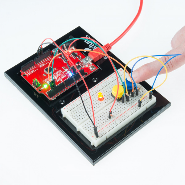
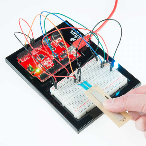
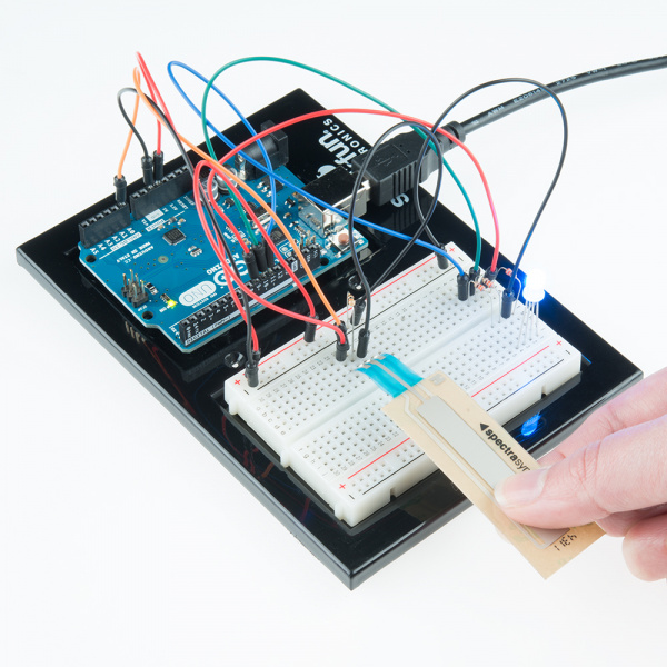
In this circuit, we are going to use yet another kind of variable resistor – this time, a soft potentiometer (or soft pot). This is a thin and flexible strip that can detect where pressure is being applied. By pressing down on various parts of the strip, you can vary the resistance from 100 to 10k ohms. You can use this ability to track movement on the soft pot, or simply as a button. In this circuit, we’ll get the soft pot up and running to control an RGB LED.
Parts Needed
You will need the following parts:
Hardware Hookup
Ready to start hooking everything up? Check out the Fritzing diagram below, to see how everything is connected.
| Polarized Components | Pay special attention to the component’s markings indicating how to place it on the breadboard. Polarized components can only be connected to a circuit in one direction. |
Fritzing Diagram for RedBoard
![RedBoard Circuit 10]()
Having a hard time seeing the circuit? Click on the Fritzing diagram to see a bigger image.
Fritzing Diagram for Arduino
![Arduino Circuit 10]()
Having a hard time seeing the circuit? Click on the Fritzing diagram to see a bigger image.
Open the Sketch
Open Up the Arduino IDE software on your computer. Coding in the Arduino language will control your circuit. Open the code for Circuit 10 by accessing the “SIK Guide Code” you downloaded and placed into your “Examples” folder earlier.
To open the code go to: File > Examples > SIK Guide Code > SIK_circuit10_softPotentiometer
You can also copy and paste the following code into the Arduino IDE. Hit upload, and see what happens!
language:cpp
 /*
SparkFun Inventor's Kit
Example sketch 10
SOFT POTENTIOMETER
  Use the soft potentiometer to change the color
  of the RGB LED
  The soft potentiometer is a neat input device that detects
  pressure along its length. When you press it down with a finger
  (it works best on a flat surface), it will change resistance
  depending on where you're pressing it. You might use it to make
  a piano or light dimmer; here we're going to use it to control
  the color of an RGB LED.

This sketch was written by SparkFun Electronics,
with lots of help from the Arduino community.
This code is completely free for any use.
Visit http://learn.sparkfun.com/products/2 for SIK information.
Visit http://www.arduino.cc to learn about the Arduino.
Version 2.0 6/2012 MDG
*/


// Constants for LED connections
const int RED_LED_PIN = 9;    // Red LED Pin
const int GREEN_LED_PIN = 10; // Green LED Pin
const int BLUE_LED_PIN = 11;  // Blue LED Pin

const int SENSOR_PIN = 0;      // Analog input pin

// Global PWM brightness values for the RGB LED.
// These are global so both loop() and setRGB() can see them.

int redValue, greenValue, blueValue;


void setup()
{
  // No need for any code here
  // analogWrite() sets up the pins as outputs
}


void loop()
{
  int sensorValue;

  sensorValue = analogRead(SENSOR_PIN); // Read the voltage from the softpot (0-1023)

  setRGB(sensorValue);  //Set a RGB LED to a position on the "rainbow" of all colors
                        //based on the sensorValue
}

void setRGB(int RGBposition)
{
  int mapRGB1, mapRGB2, constrained1, constrained2;

  mapRGB1 = map(RGBposition, 0, 341, 255, 0);
  constrained1 = constrain(mapRGB1, 0, 255);

  mapRGB2 = map(RGBposition, 682, 1023, 0, 255);
  constrained2 = constrain(mapRGB2, 0, 255);

  redValue = constrained1 + constrained2; //Create the red peak

  //Create the green peak
  //Note that we are nesting functions (which requires fewer variables)

  greenValue = constrain(map(RGBposition, 0, 341, 0, 255), 0, 255)
             - constrain(map(RGBposition, 341, 682, 0,255), 0, 255);

  //Create the blue peak
  blueValue = constrain(map(RGBposition, 341, 682, 0, 255), 0, 255)
            - constrain(map(RGBposition, 682, 1023, 0, 255), 0, 255);

 // Display the new computed "rainbow" color
  analogWrite(RED_LED_PIN, redValue);
  analogWrite(GREEN_LED_PIN, greenValue);
  analogWrite(BLUE_LED_PIN, blueValue);

  }
Code To Note
language:cpp
redValue = constrain(map(RGBposition, 0, 341, 255, 0), 0, 255)
 + constrain(map(RGBposition, 682, 1023, 0, 255), 0, 255);


greenValue = constrain(map(RGBposition, 0, 341, 0, 255), 0, 255)
 - constrain(map(RGBposition, 341, 682, 0,255), 0, 255);


blueValue = constrain(map(RGBposition, 341, 682, 0, 255), 0, 255)
- constrain(map(RGBposition, 682, 1023, 0, 255), 0, 255);
These big, scary functions take a single Value (RGBposition) and calculate the three RGB values necessary to create a rainbow of color. The functions create three “peaks” for the red, green, and blue values, which overlap to mix and create new colors. See the code for more information! Even if you’re not 100% clear how it works, you can copy and paste this (or any) function into your own code and use it yourself.
What You Should See
You should see the RGB LED change colors in accordance with how you interact with the soft potentiometer. If it isn’t working, make sure you have assembled the circuit correctly and verified and uploaded the code to your board, or see the troubleshooting section.
Real World Application
The knobs found on many objects, like a radio for instance, are using similar concepts to the one you just completed for this circuit.
Troubleshooting
LED Remains Dark or Shows Incorrect Color
With the four pins of the LED so close together, it’s sometimes easy to misplace one. Try double checking each
pin is where it should be.
Bizarre Results
The most likely cause of this is if you’re pressing the
potentiometer in more than one position. This is normal
and can actually be used to create some neat results.
Experiment 11: Using a Piezo Buzzer
Introduction
In this circuit, we’ll again bridge the gap between the digital world and the analog world. We’ll be using a piezo buzzer that makes a small “click” when you apply voltage to it (try it!). By itself that isn’t terribly exciting, but if you turn the voltage on and off hundreds of times a second, the piezo buzzer will produce a tone. And if you string a bunch of tones together, you’ve got music! This circuit and sketch will play a classic tune. We’ll never let you down!
Parts Needed
You will need the following parts:
Hardware Hookup
Ready to start hooking everything up? Check out the Fritzing diagram below, to see how everything is connected.
| Polarized Components | Pay special attention to the component’s markings indicating how to place it on the breadboard. Polarized components can only be connected to a circuit in one direction. |
Fritzing Diagram for RedBoard
![alt text]()
Having a hard time seeing the circuit? Click on the Fritzing diagram to see a bigger image.
Fritzing Diagram for Arduino
![alt text]()
Having a hard time seeing the circuit? Click on the Fritzing diagram to see a bigger image.
Open the Sketch
Open Up the Arduino IDE software on your computer. Coding in the Arduino language will control your circuit. Open the code for Circuit 11 by accessing the “SIK Guide Code” you downloaded and placed into your “Examples” folder earlier.
To open the code go to: File > Examples > SIK Guide Code > SIK_circuit11_buzzer
You can also copy and paste the following code into the Arduino IDE. Hit upload, and see what happens!
language:cpp
 /******************************************************************
 * SparkFun Inventor's Kit
 * Example sketch 11
 *
 * BUZZER
 *
 * This sketch uses the buzzer to play songs.
 * The Arduino's tone() command will play notes of a given frequency.
 *
 * This sketch was written by SparkFun Electronics,
 * with lots of help from the Arduino community.
 * (This sketch was originally developed by D. Cuartielles for K3)
 * This code is completely free for any use.
 * Visit http://learn.sparkfun.com/products/2 for SIK information.
 * Visit http://www.arduino.cc to learn about the Arduino.
 *
 * Version 2.0 6/2012 MDG
 * Version 2.1 9/2014 BCH
 *****************************************************************/


const int buzzerPin = 9;    // connect the buzzer to pin 9
const int songLength = 18;  // sets the number of notes of the song

// Notes is an array of text characters corresponding to the notes
// in your song. A space represents a rest (no tone)

char notes[songLength] = {
  'c', 'd', 'f', 'd', 'a', ' ', 'a', 'g', ' ', 'c', 'd', 'f', 'd', 'g', ' ', 'g', 'f', ' '};

// beats[] is an array of values for each note. A "1" represents a quarter-note,
// "2" a half-note, and "4" a quarter-note.
// Don't forget that the rests (spaces) need a length as well.

int beats[songLength] = {
  1, 1, 1, 1, 1, 1, 4, 4, 2, 1, 1, 1, 1, 1, 1, 4, 4, 2};

int tempo = 113;  // The tempo is how fast to play the song (beats per second).

void setup()
{
  pinMode(buzzerPin, OUTPUT);  // sets the  buzzer pin as an OUTPUT
}


void loop()
{
  int i, duration; //

  for (i = 0; i < songLength; i++) // for loop is used to index through the arrays
  {
    duration = beats[i] * tempo;  // length of note/rest in ms

    if (notes[i] == ' ')          // is this a rest?
      delay(duration);            // then pause for a moment
    else                          // otherwise, play the note
    {
      tone(buzzerPin, frequency(notes[i]), duration);
      delay(duration);            // wait for tone to finish
    }
    delay(tempo/10);              // brief pause between notes
  }

  while(true){
  // We only want to play the song once, so we pause forever
  }
  // If you'd like your song to play over and over, remove the while(true)
  // statement above
}

int frequency(char note)
{
  int i;
  const int numNotes = 8;  // number of notes we're storing
  char names[numNotes] = {
    'c', 'd', 'e', 'f', 'g', 'a', 'b', 'C'    };
  int frequencies[numNotes] = {
    262, 294, 330, 349, 392, 440, 494, 523    };

  // Now we'll search through the letters in the array, and if
  // we find it, we'll return the frequency for that note.

  for (i = 0; i < numNotes; i++)  // Step through the notes
  {
    if (names[i] == note)         // Is this the one?
    {
      return(frequencies[i]);     // Yes! Return the frequency and exit function.
    }
  }
  return(0);  // We looked through everything and didn't find it,
  // but we still need to return a value, so return 0.
}
Code To Note
char notes[] = "cdfda ag cdfdg gf ";
char names[] = {'c','d','e','f','g','a','b','C'};
Up until now we’ve been working solely with numerical data, but the Arduino can also work with text. Characters (single, printable, letters, numbers and other symbols) have their own type, called “char”. When you have an array of characters, it can be defined between double-quotes (also called a “string”), OR as a list of single-quoted characters.
tone(pin, frequency, duration);
One of Arduino’s many useful built-in commands is the tone() function. This function drives an output pin at a certain frequency, making it perfect for driving buzzers and speakers. If you give it a duration (in milliseconds), it will play the tone then stop. If you don’t give it a duration, it will keep playing the tone forever (but you can stop it with another function, noTone() ).
What You Should See
You should see - well, nothing! But you should be able to hear a song. If it isn’t working, make sure you have assembled the circuit correctly and verified and uploaded the code to your board or see the troubleshooting section.
Real World Application
Many modern megaphones have settings that use a loud amplified buzzer. They are usually very loud and quite good at getting people’s attention.
Troubleshooting
No Sound
Given the size and shape of the piezo buzzer it is easy to miss the right holes on the breadboard. Try double checking its placement.
Can’t Think While the Melody is Playing
Just pull up the piezo buzzer or one of the wires whilst you think, upload your program then plug it back in.
Feeling Let Down and Deserted
The code is written so you can easily add your own songs.
Experiment 12: Driving a Motor
Introduction
Back in experiment 8, you got to work with a servo motor. Now, we are going to tackle spinning a motor. This requires the use of a transistor, which can switch a larger amount of current than the RedBoard or Arduino Uno R3 can.
When using a transistor, you just need to make sure its maximum specs are high enough for your use case. The transistor we are using for this circuit is rated at 50V max and 800 milliamps max – perfect for our toy motor! When the motor is spinning and suddenly turned off, the magnetic field inside it collapses, generating a voltage spike. This can damage the transistor. To prevent this, we use a “flyback diode”, which diverts the voltage spike around the transistor.
Parts Needed
You will need the following parts:
Suggested Reading
Before continuing on with this experiment, we recommend you be familiar with the concepts in the following tutorial:
Hardware Hookup
Ready to start hooking everything up? Check out the Fritzing diagram below, to see how everything is connected.
| Polarized Components | Pay special attention to the component’s markings indicating how to place it on the breadboard. Polarized components can only be connected to a circuit in one direction. |
Please note: When you’re building the circuit be careful not to mix up the transistor and the temperature sensor, they’re almost identical. Look for “BC337” on the body of the transistor.
Fritzing Diagram for RedBoard
![RedBoard Circuit 12]()
Having a hard time seeing the circuit? Click on the Fritzing diagram to see a bigger image.
Fritzing Diagram for Arduino
![Arduino Circuit 12]()
Having a hard time seeing the circuit? Click on the Fritzing diagram to see a bigger image.
Open the Sketch
Open Up the Arduino IDE software on your computer. Coding in the Arduino language will control your circuit. Open the code for Circuit 12 by accessing the “SIK Guide Code” you downloaded and placed into your “Examples” folder earlier.
To open the code go to: File > Examples > SIK Guide Code > SIK_circuit12_motorSpin
You can also copy and paste the following code into the Arduino IDE. Hit upload, and see what happens!
language:cpp
/********************************************************************
 * SparkFun Inventor's Kit
 * Example sketch 12
 *
 * SPINNING A MOTOR
 *
 * This example requires that you drive your motor using a switching
 * transistor. The Arduino is only capable of sourcing about 40 mA of
 * current per pin and a motor requires upwards of 150 mA.
 *
 * Look at the wiring diagram in the SIK Guide - Circuit #12 or read the
 * notes in the readme tab for more information on wiring.
 *
 * This sketch was written by SparkFun Electronics,
 * with lots of help from the Arduino community.
 * This code is completely free for any use.
 * Visit http://learn.sparkfun.com/products/2 for SIK information.
 * Visit http://www.arduino.cc to learn about the Arduino.
 *
 * Version 2.0 6/2012 MDG
 * Version 2.1 8/2014 BCH
 *******************************************************************/

const int motorPin = 9;  // Connect the base of the transistor to pin 9.
                         // Even though it's not directly connected to the motor,
                         // we'll call it the 'motorPin'

void setup()
{
  pinMode(motorPin, OUTPUT);  // set up the pin as an OUTPUT
  Serial.begin(9600);         // initialize Serial communications
}


void loop()
{ // This example basically replicates a blink, but with the motorPin instead.
  int onTime = 3000;  // milliseconds to turn the motor on
  int offTime = 3000; // milliseconds to turn the motor off

  analogWrite(motorPin, 255); // turn the motor on (full speed)
  delay(onTime);                // delay for onTime milliseconds
  analogWrite(motorPin, 0);  // turn the motor off
  delay(offTime);               // delay for offTime milliseconds

  // Uncomment the functions below by taking out the //. Look below for the
  // code examples or documentation.

  // speedUpandDown();
  // serialSpeed();
}

// This function accelerates the motor to full speed,
// then decelerates back down to a stop.
void speedUpandDown()
{
  int speed;
  int delayTime = 20; // milliseconds between each speed step

  // accelerate the motor
  for(speed = 0; speed <= 255; speed++)
  {
    analogWrite(motorPin,speed);    // set the new speed
    delay(delayTime);               // delay between speed steps
  }
  // decelerate the motor
  for(speed = 255; speed >= 0; speed--)
  {
    analogWrite(motorPin,speed);    // set the new speed
    delay(delayTime);               // delay between speed steps
  }
}


// Input a speed from 0-255 over the Serial port
void serialSpeed()
{
  int speed;

  Serial.println("Type a speed (0-255) into the box above,");
  Serial.println("then click [send] or press [return]");
  Serial.println();  // Print a blank line

  // In order to type out the above message only once,
  // we'll run the rest of this function in an infinite loop:

  while(true)  // "true" is always true, so this will loop forever.
  {
    // Check to see if incoming data is available:
    while (Serial.available() > 0)
    {
      speed = Serial.parseInt();  // parseInt() reads in the first integer value from the Serial Monitor.
      speed = constrain(speed, 0, 255); // constrains the speed between 0 and 255
                                        // because analogWrite() only works in this range.

      Serial.print("Setting speed to ");  // feedback and prints out the speed that you entered.
      Serial.println(speed);

      analogWrite(motorPin, speed);  // sets the speed of the motor.
    }
  }
}
Code To Note
while (Serial.available() > 0)
The Arduino’s serial port can be used to receive as well as send data. Because data could arrive at any time, the Arduino stores, or “buffers” data coming into the port until you’re ready to use it. The Serial.available() command returns the number of characters that the port has received, but haven’t been used by your sketch yet. Zero means no data has arrived.
speed = Serial.parseInt();
If the port has data waiting for you, there are a number of ways for you to use it. Since we’re typing numbers into the port, we can use the handy Serial.parseInt() command to extract, or “parse” integer numbers from the characters it’s received. If you type “1” “0” “0” to the port, this function will return the number 100.
What You Should See
The DC Motor should spin if you have assembled the circuit’s components correctly, and also verified/uploaded the correct code. If your circuit is not working check the troubleshooting section.
Real World Application
Radio Controlled (RC) cars use Direct Current (DC) motors to turn the wheels for propulsion.
Troubleshooting
Motor Not Spinning
If you sourced your own transistor, double check with the data sheet that the pinout is compatible with a BC337 (many are reversed).
Still No Luck
If you sourced your own motor, double check that it will work with 5 volts and that it does not draw too much power.
Still Not Working
Sometimes the Arduino will disconnect from the computer. Try un-plugging and then re-plugging it into your USB port.
Experiment 13: Using Relays
Introduction
In this circuit, we are going to use some of the lessons we learned in experiment 12 to control a relay. A relay is basically an electrically controlled mechanical switch. Inside that harmless looking plastic box is an electromagnet that, when it gets a jolt of energy, causes a switch to trip. In this circuit, you’ll learn how to control a relay like a pro – giving your Arduino even more powerful abilities!
Parts Needed
You will need the following parts:
Suggested Reading
Before continuing on with this experiment, we recommend you be familiar with the concepts in the following tutorial:
Hardware Hookup
Ready to start hooking everything up? Check out the Fritzing diagram below, to see how everything is connected.
| Polarized Components | Pay special attention to the component’s markings indicating how to place it on the breadboard. Polarized components can only be connected to a circuit in one direction. |
Fritzing Diagram for RedBoard
![RedBoard Circuit 13]()
Having a hard time seeing the circuit? Click on the Fritzing diagram to see a bigger image.
Fritzing Diagram for Arduino
![Arduino Circuit 13]()
Having a hard time seeing the circuit? Click on the Fritzing diagram to see a bigger image.
Open the Sketch
Open Up the Arduino IDE software on your computer. Coding in the Arduino language will control your circuit. Open the code for Circuit 13 by accessing the “SIK Guide Code” you downloaded and placed into your “Examples” folder earlier.
To open the code go to: File > Examples > SIK Guide Code > SIK_circuit13_relays
You can also copy and paste the following code into the Arduino IDE. Hit upload, and see what happens!
language:cpp
/********************************************************************
 * SparkFun Inventor's Kit
 * Example sketch 13
 *
 * RELAYS
 *
 * A relay is a electrically-controlled mechanical switch. It has an
 * electro-magnetic coil that either opens or closes a switch. Because
 * it is a physical switch, a relay can turn on and off large devices
 * like BIG motors, spot lights, and lamps.
 *
 * To create enough current to excite the electro-magnet, we need to use
 * the transistor circuit from the last example. Each time we excite the relay
 * you should hear an audible clicking sound of the switch.
 *
 * This sketch was written by SparkFun Electronics,
 * with lots of help from the Arduino community.
 * This code is completely free for any use.
 *
 * Visit http://learn.sparkfun.com/sik for SIK information.
 * Visit http://www.arduino.cc to learn about the Arduino.
 *
 * Version 2.0 6/2012 MDG
 * Version 2.1 8/2014 BCH
 *******************************************************************/

const int relayPin = 2;     // This pin drives the transistor (which drives the relay)
const int timeDelay = 1000; // delay in ms for on and off phases

// You can make timeDelay shorter, but note that relays, being
// mechanical devices, will wear out quickly if you try to drive
// them too fast.


void setup()
{
  pinMode(relayPin, OUTPUT);  // set pin as an output
}


void loop()
{
  digitalWrite(relayPin, HIGH);  // turn the relay on

  delay(timeDelay);              // wait for one second

  digitalWrite(relayPin, LOW);   // turn the relay off

  delay(timeDelay);              // wait for one second
}
Code To Note
digitalWrite(relayPin, HIGH);
When we turn on the transistor, which in turn energizes the relay’s coil, the relay’s switch contacts are closed. This connects the relay’s COM pin to the NO (Normally Open) pin. Whatever you’ve connected using these pins will turn on. (Here we’re using LEDs, but this could be almost anything.)
digitalWrite(relayPin, LOW);
The relay has an additional contact called NC (Normally Closed). The NC pin is connected to the COM pin when the relay is OFF. You can use either pin depending on whether something should be normally on or normally off. You can also use both pins to alternate power to two devices, much like railroad crossing warning lights.
What You Should See
You should be able to hear the relay contacts click, and see the two LEDs alternate illuminating at 1-second intervals. If you don’t, double-check that you have assembled the circuit correctly, and uploaded the correct sketch to the board. Also, see the troubleshooting section.
Real World Application
Garage door openers use relays to operate. You might be able to hear the clicking if you listen closely.
Troubleshooting
LEDs Not Lighting
Double-check that you’ve plugged them in correctly. The longer lead (and non-flat edge of the plastic flange) is the positive lead.
No Clicking Sound
The transistor or coil portion of the circuit isn’t quite working. Check the transistor is plugged in the right way.
Not Quite Working
The included relays are designed to be soldered rather than used in a breadboard. As such you may need to press it in to ensure it works (and it may pop out occasionally).
When you’re building the circuit be careful not to mix up the temperature sensor and the transistor, they’re almost identical.
Experiment 14: Using a Shift Register
Introduction
Now we are going to step into the world of ICs (integrated circuits). In this circuit, you’ll learn all about using a shift register (also called a serial-to-parallel converter). The shift register will give your RedBoard or Arduino Uno R3 an additional eight outputs, using only three pins on your board. For this circuit, you’ll practice by using the shift register to control eight LEDs.
Parts Needed
You will need the following parts:
Suggested Reading
Before continuing on with this experiment, we recommend you be familiar with the concepts in the following tutorial:
Hardware Hookup
Ready to start hooking everything up? Check out the Fritzing diagram below, to see how everything is connected.
| Polarized Components | Pay special attention to the component’s markings indicating how to place it on the breadboard. Polarized components can only be connected to a circuit in one direction. |
For the shift register, align notch on top, in-between “e1” and “f1” on the breadboard. The notch indicates where pin 1 is.
Fritzing Diagram for RedBoard
![RedBoard Circuit 14]()
Having a hard time seeing the circuit? Click on the Fritzing diagram to see a bigger image.
Fritzing Diagram for Arduino
![Arduino Circuit 14]()
Having a hard time seeing the circuit? Click on the Fritzing diagram to see a bigger image.
Open the Sketch
Open Up the Arduino IDE software on your computer. Coding in the Arduino language will control your circuit. Open the code for Circuit 14 by accessing the “SIK Guide Code” you downloaded and placed into your “Examples” folder earlier.
To open the code go to: File > Examples > SIK Guide Code > SIK_circuit14_shiftRegister
You can also copy and paste the following code into the Arduino IDE. Hit upload, and see what happens!
language:cpp
/*
SparkFun Inventor's Kit
Example sketch 14
SHIFT REGISTER
  Use a shift register to turn three pins into eight (or more!)
  outputs
  An integrated circuit ("IC"), or "chip", is a self-contained
  circuit built into a small plastic package. (If you look closely
  at your Arduino board you'll see a number of ICs.) There are
  thousands of different types of ICs available that you can use
  to perform many useful functions.
  The 74HC595 shift register in your kit is an IC that has eight
  digital outputs. To use these outputs, we'll use a new interface
  called SPI (Serial Peripheral Interface). It's like the TX and
  RX you're used to, but has an additional "clock" line that
  controls the speed of the data transfer. Many parts use SPI
  for communications, so the Arduino offers simple commands called
  shiftIn() and shiftOut() to access these parts.
  This IC lets you use three digital pins on your Arduino to
  control eight digital outputs on the chip. And if you need
  even more outputs, you can daisy-chain multiple shift registers
  together, allowing an almost unlimited number of outputs from
  the same three Arduino pins! See the shift register datasheet
  for details:

  http://www.sparkfun.com/datasheets/IC/SN74HC595.pdf

This sketch was written by SparkFun Electronics,
with lots of help from the Arduino community.
This code is completely free for any use.
Visit http://learn.sparkfun.com/products/2 for SIK information.
Visit http://www.arduino.cc to learn about the Arduino.
Version 2.0 6/2012 MDG
*/


// Pin definitions:
// The 74HC595 uses a type of serial connection called SPI
// (Serial Peripheral Interface) that requires three pins:

int datapin = 2;
int clockpin = 3;
int latchpin = 4;

// We'll also declare a global variable for the data we're
// sending to the shift register:

byte data = 0;


void setup()
{
  // Set the three SPI pins to be outputs:

  pinMode(datapin, OUTPUT);
  pinMode(clockpin, OUTPUT);
  pinMode(latchpin, OUTPUT);
}


void loop()
{

  // To try the different functions below, uncomment the one
  // you want to run, and comment out the remaining ones to
  // disable them from running.

  oneAfterAnother();      // All on, all off

  //oneOnAtATime();       // Scroll down the line

  //pingPong();           // Like above, but back and forth

  //randomLED();          // Blink random LEDs

  //marquee();

  //binaryCount();        // Bit patterns from 0 to 255
}


void shiftWrite(int desiredPin, boolean desiredState)

// This function lets you make the shift register outputs
// HIGH or LOW in exactly the same way that you use digitalWrite().

  bitWrite(data,desiredPin,desiredState); //Change desired bit to 0 or 1 in "data"

  // Now we'll actually send that data to the shift register.
  // The shiftOut() function does all the hard work of
  // manipulating the data and clock pins to move the data
  // into the shift register:

  shiftOut(datapin, clockpin, MSBFIRST, data); //Send "data" to the shift register

  //Toggle the latchPin to make "data" appear at the outputs
  digitalWrite(latchpin, HIGH);
  digitalWrite(latchpin, LOW);
}


void oneAfterAnother()
{
// This function will turn on all the LEDs, one-by-one,
// and then turn them off all off, one-by-one.

  int index;
  int delayTime = 100; // Time (milliseconds) to pause between LEDs
                       // Make this smaller for faster switching

  // Turn all the LEDs on
  for(index = 0; index <= 7; index++)
  {
    shiftWrite(index, HIGH);
    delay(delayTime);
  }

  // Turn all the LEDs off
  for(index = 7; index >= 0; index--)
  {
    shiftWrite(index, LOW);
    delay(delayTime);
  }
}


void oneOnAtATime()
{
// This function will turn the LEDs on and off, one-by-one.
  int index;
  int delayTime = 100; // Time (milliseconds) to pause between LEDs
                       // Make this smaller for faster switching

  // step through the LEDs, from 0 to 7

  for(index = 0; index <= 7; index++)
  {
    shiftWrite(index, HIGH);    // turn LED on
    delay(delayTime);       // pause to slow down the sequence
    shiftWrite(index, LOW); // turn LED off
  }
}

void pingPong()
{
// This function turns on the LEDs, one at a time, in both directions.
  int index;
  int delayTime = 100; // time (milliseconds) to pause between LEDs
                       // make this smaller for faster switching

  // step through the LEDs, from 0 to 7

  for(index = 0; index <= 7; index++)
  {
    shiftWrite(index, HIGH);    // turn LED on
    delay(delayTime);       // pause to slow down the sequence
    shiftWrite(index, LOW); // turn LED off
  }

  // step through the LEDs, from 7 to 0

  for(index = 7; index >= 0; index--)
  {
    shiftWrite(index, HIGH);    // turn LED on
    delay(delayTime);       // pause to slow down the sequence
    shiftWrite(index, LOW); // turn LED off
  }
}

void randomLED()
{
// This function will randomly turn on and off LEDs.
  int index;
  int delayTime = 100; // time (milliseconds) to pause between LEDs
                       // make this smaller for faster switching

  index = random(8);    // pick a random number between 0 and 7

  shiftWrite(index, HIGH);  // turn LED on
  delay(delayTime);     // pause to slow down the sequence
  shiftWrite(index, LOW);   // turn LED off
}

void marquee()
{
// This function will mimic "chase lights" like those around signs.
  int index;
  int delayTime = 200; // Time (milliseconds) to pause between LEDs
                       // Make this smaller for faster switching

  // Step through the first four LEDs
  // (We'll light up one in the lower 4 and one in the upper 4)

  for(index = 0; index <= 3; index++)
  {
    shiftWrite(index, HIGH);    // Turn a LED on
    shiftWrite(index+4, HIGH);  // Skip four, and turn that LED on
    delay(delayTime);       // Pause to slow down the sequence
    shiftWrite(index, LOW); // Turn both LEDs off
    shiftWrite(index+4, LOW);
  }
}


void binaryCount()
{
// This function creates a visual representation of the on/off pattern
// of bits in a byte.

  int delayTime = 1000; // time (milliseconds) to pause between LEDs
                        // make this smaller for faster switching

  // Send the data byte to the shift register:

  shiftOut(datapin, clockpin, MSBFIRST, data);

  // Toggle the latch pin to make the data appear at the outputs:

  digitalWrite(latchpin, HIGH);
  digitalWrite(latchpin, LOW);

  // Add one to data, and repeat!
  // (Because a byte type can only store numbers from 0 to 255,
  // if we add more than that, it will "roll around" back to 0
  // and start over).

  data++;

  // Delay so you can see what's going on:

  delay(delayTime);
}
Code To Note
shiftOut(datapin, clockpin, MSBFIRST, data);
You’ll communicate with the shift register (and a lot of other parts) using an interface called SPI, or Serial Peripheral Interface. This interface uses a data line and a separate clock line that work together to move data into or out of the Arduino at high speed. The MSBFIRST parameter specifies the order in which to send the individual bits, in this case we’re sending the Most Significant Bit first.
bitWrite(data, desiredPin, desiredState);
Bits are the smallest possible piece of memory in a computer; each one can store either a “1” or a “0”. Larger numbers are stored as arrays of bits. Sometimes we want to manipulate these bits directly, for example now when we’re sending eight bits to the shift register and we want to make them 1 or 0 to turn the LEDs on or off. The Arduino has several commands, such as bitWrite(), that make this easy to do.
What You Should See
You should see the LEDs light up similarly to experiment 4 (but this time, you’re using a shift register). If they aren’t, make sure you have assembled the circuit correctly and verified and uploaded the code to your board. See the troubleshooting section.
Real World Application
Similar to experiment 4, a scrolling marquee display delivers a message with multiple LEDs. Essentially the same task the shift register achieves here in experiment 14.
You might be asking yourself, “why bother using a shift register if we already have more than 8 outputs?” One reason is that you may have a project where you’ve already used up most of your output pins for other uses. A shift register allows you to add eight more output pins for the price of only three!
Troubleshooting
The Arduino’s power LED goes out
This happened to us a couple of times, it happens when the chip is inserted backward. If you fix it quickly nothing will break.
Not Quite Working
Sorry to sound like a broken record, but it is probably something as simple as a crossed wire.
Frustration
Shoot us an e-mail, this circuit is both simple and complex at the same time. We want to hear about problems you have so we can address them in future editions: techsupport@sparkfun.com
Experiment 15: Using an LCD
Introduction
In this circuit, you’ll learn about how to use an LCD. An LCD, or liquid crystal display, is a simple screen that can display commands, bits of information, or readings from your sensor - all depending on how you program your board. In this circuit, you’ll learn the basics of incorporating an LCD into your project.
Parts Needed
You will need the following parts:
Hardware Hookup
Ready to start hooking everything up? Check out the Fritzing diagram below, to see how everything is connected.
| Polarized Components | Pay special attention to the component’s markings indicating how to place it on the breadboard. Polarized components can only be connected to a circuit in one direction. |
Fritzing Diagram for RedBoard
![alt text]()
Having a hard time seeing the circuit? Click on the Fritzing diagram to see a bigger image.
Fritzing Diagram for Arduino
![alt text]()
Open the Sketch
Open Up the Arduino IDE software on your computer. Coding in the Arduino language will control your circuit. Open the code for Circuit 15 by accessing the “SIK Guide Code” you downloaded and placed into your “Examples” folder earlier.
To open the code go to: File > Examples > SIK Guide Code > SIK_circuit15_LCDscreen
You can also copy and paste the following code into the Arduino IDE. Hit upload, and see what happens!
language:cpp
/*
SparkFun Inventor's Kit
Example sketch 15
LIQUID CRYSTAL DISPLAY (LCD)
  A Liquid Crystal Display (LCD) is a sophisticated module
  that can be used to display text or numeric data. The display
  included in your SIK features two lines of 16 characters, and
  a backlight so it can be used at night.
  If you've been using the Serial Monitor to output data,
  you'll find that a LCD provides many of the same benefits
  without needing to drag a large computer around.
  This sketch will show you how to connect an LCD to your Arduino
  and display any data you wish.
This sketch was written by SparkFun Electronics,
with lots of help from the Arduino community.
This code is completely free for any use.
Visit http://learn.sparkfun.com/products/2 for SIK information.
Visit http://www.arduino.cc to learn about the Arduino.
Version 1.0 2/2013 MDG
*/

// Load the LiquidCrystal library, which will give us
// commands to interface to the LCD:

#include <LiquidCrystal.h>

// Initialize the library with the pins we're using.
// (Note that you can use different pins if needed.)
// See http://arduino.cc/en/Reference/LiquidCrystal
// for more information:

LiquidCrystal lcd(12, 11, 5, 4, 3, 2);

void setup()
{

    lcd.begin(16, 2); //Initialize the 16x2 LCD


    lcd.clear();    //Clear any old data displayed on the LCD


    lcd.print("hello, world!"); // Display a message on the LCD!


}

void loop()
{

    lcd.setCursor(0, 1);    //Set the (invisible) cursor to column 0,
                            // row 1.

    lcd.print(millis() / 1000); //Print the number of seconds
                                //since the Arduino last reset.
}
Code To Note
#include <LiquidCrystal.h>
This bit of code tells your Arduino IDE to include the library for a simple LCD display. Without it, none of the commands will work, so make sure you include it!
lcd.print(“hello, world!”);
This is the first time you’ll fire something up on your screen. You may need to adjust the contrast to make it visible. Twist the potentiometer until you can clearly see the text!
What You Should See
Initially, you should see the words “hello, world!” pop up on your LCD. Remember you can adjust the contrast using the potentiometer if you can’t make out the words clearly. If you have any issues, make sure your code is correct and double-check your connections.
Real World Application
LCDs are everywhere! From advanced LCDs like your television, to simple notification screens, this is a very common and useful display!
The Screen is Blank or Completely Lit?
Fiddle with the contrast by twisting the potentiometer. If it’s incorrectly adjusted, you won’t be able to read the text.
Not Working At All?
Double check the code, specifically that you include the LCD library.
Screen Is Flickering
Double check your connections to your breadboard and Arduino.
Experiment 16: Simon Says
Introduction
Now that we’ve learned all the basics behind the components in the SIK experiments, let’s put them all together to make something fun! This circuit will show you how to create your own Simon Says game. Using some LEDs, some buttons, a buzzer, and some resistors, you can create this and other exciting games with the RedBoard or Arduino Uno R3.
Parts Needed
You will need the following parts:
Hardware Hookup
Ready to start hooking everything up? Check out the Fritzing diagram below, to see how everything is connected.
| Polarized Components | Pay special attention to the component’s markings indicating how to place it on the breadboard. Polarized components can only be connected to a circuit in one direction. |
Fritzing Diagram for RedBoard
![RedBoard Circuit 16]()
Having a hard time seeing the circuit? Click on the Fritzing diagram to see a bigger image.
Fritzing Diagram for Arduino
![Arduino Circuit 16]()
Open the Sketch
Open Up the Arduino IDE software on your computer. Coding in the Arduino language will control your circuit. Open the code for Circuit 16 by accessing the “SIK Guide Code” you downloaded and placed into your “Examples” folder earlier.
To open the code go to: File > Examples > SIK Guide Code > SIK_circuit16_simonGame
You can also copy and paste the following code into the Arduino IDE. Hit upload, and see what happens!
language:cpp
/*
 SparkFun Inventor's Kit
 Example sketch 16

 SIMON SAYS
 Simon Says is a memory game. Start the game by pressing one of the four buttons. When a button lights up,
 press the button, repeating the sequence. The sequence will get longer and longer. The game is won after
 13 rounds.
 Generates random sequence, plays music, and displays button lights.
 Simon tones from Wikipedia
 - A (red, upper left) - 440Hz - 2.272ms - 1.136ms pulse
 - a (green, upper right, an octave higher than A) - 880Hz - 1.136ms,
 0.568ms pulse
 - D (blue, lower left, a perfect fourth higher than the upper left)
 587.33Hz - 1.702ms - 0.851ms pulse
 - G (yellow, lower right, a perfect fourth higher than the lower left) -
 784Hz - 1.276ms - 0.638ms pulse
 Simon Says game originally written in C for the PIC16F88.
 Ported for the ATmega168, then ATmega328, then Arduino 1.0.
 Fixes and cleanup by Joshua Neal <joshua[at]trochotron.com>
 This sketch was written by SparkFun Electronics,
 with lots of help from the Arduino community.
 This code is completely free for any use.
 Visit http://www.arduino.cc to learn about the Arduino.

 */

/*************************************************
* Public Constants
*************************************************/
#define NOTE_B0 31
#define NOTE_C1 33
#define NOTE_CS1 35
#define NOTE_D1 37
#define NOTE_DS1 39
#define NOTE_E1 41
#define NOTE_F1 44
#define NOTE_FS1 46
#define NOTE_G1 49
#define NOTE_GS1 52
#define NOTE_A1 55
#define NOTE_AS1 58
#define NOTE_B1 62
#define NOTE_C2 65
#define NOTE_CS2 69
#define NOTE_D2 73
#define NOTE_DS2 78
#define NOTE_E2 82
#define NOTE_F2 87
#define NOTE_FS2 93
#define NOTE_G2 98
#define NOTE_GS2 104
#define NOTE_A2 110
#define NOTE_AS2 117
#define NOTE_B2 123
#define NOTE_C3 131
#define NOTE_CS3 139
#define NOTE_D3 147
#define NOTE_DS3 156
#define NOTE_E3 165
#define NOTE_F3 175
#define NOTE_FS3 185
#define NOTE_G3 196
#define NOTE_GS3 208
#define NOTE_A3 220
#define NOTE_AS3 233
#define NOTE_B3 247
#define NOTE_C4 262
#define NOTE_CS4 277
#define NOTE_D4 294
#define NOTE_DS4 311
#define NOTE_E4 330
#define NOTE_F4 349
#define NOTE_FS4 370
#define NOTE_G4 392
#define NOTE_GS4 415
#define NOTE_A4 440
#define NOTE_AS4 466
#define NOTE_B4 494
#define NOTE_C5 523
#define NOTE_CS5 554
#define NOTE_D5 587
#define NOTE_DS5 622
#define NOTE_E5 659
#define NOTE_F5 698
#define NOTE_FS5 740
#define NOTE_G5 784
#define NOTE_GS5 831
#define NOTE_A5 880
#define NOTE_AS5 932
#define NOTE_B5 988
#define NOTE_C6 1047
#define NOTE_CS6 1109
#define NOTE_D6 1175
#define NOTE_DS6 1245
#define NOTE_E6 1319
#define NOTE_F6 1397
#define NOTE_FS6 1480
#define NOTE_G6 1568
#define NOTE_GS6 1661
#define NOTE_A6 1760
#define NOTE_AS6 1865
#define NOTE_B6 1976
#define NOTE_C7 2093
#define NOTE_CS7 2217
#define NOTE_D7 2349
#define NOTE_DS7 2489
#define NOTE_E7 2637
#define NOTE_F7 2794
#define NOTE_FS7 2960
#define NOTE_G7 3136
#define NOTE_GS7 3322
#define NOTE_A7 3520
#define NOTE_AS7 3729
#define NOTE_B7 3951
#define NOTE_C8 4186
#define NOTE_CS8 4435
#define NOTE_D8 4699
#define NOTE_DS8 4978

#define CHOICE_OFF      0 //Used to control LEDs
#define CHOICE_NONE     0 //Used to check buttons
#define CHOICE_RED  (1 << 0)
#define CHOICE_GREEN    (1 << 1)
#define CHOICE_BLUE (1 << 2)
#define CHOICE_YELLOW   (1 << 3)

#define LED_RED     10
#define LED_GREEN   3
#define LED_BLUE    13
#define LED_YELLOW  5

// Button pin definitions
#define BUTTON_RED    9
#define BUTTON_GREEN  2
#define BUTTON_BLUE   12
#define BUTTON_YELLOW 6

// Buzzer pin definitions
#define BUZZER1  4
#define BUZZER2  7

// Define game parameters
#define ROUNDS_TO_WIN      13 //Number of rounds to succesfully remember before you win. 13 is do-able.
#define ENTRY_TIME_LIMIT   3000 //Amount of time to press a button before game times out. 3000ms = 3 sec

#define MODE_MEMORY  0
#define MODE_BATTLE  1
#define MODE_BEEGEES 2

// Game state variables
byte gameMode = MODE_MEMORY; //By default, let's play the memory game
byte gameBoard[32]; //Contains the combination of buttons as we advance
byte gameRound = 0; //Counts the number of succesful rounds the player has made it through

void setup()
{
  //Setup hardware inputs/outputs. These pins are defined in the hardware_versions header file

  //Enable pull ups on inputs
  pinMode(BUTTON_RED, INPUT_PULLUP);
  pinMode(BUTTON_GREEN, INPUT_PULLUP);
  pinMode(BUTTON_BLUE, INPUT_PULLUP);
  pinMode(BUTTON_YELLOW, INPUT_PULLUP);

  pinMode(LED_RED, OUTPUT);
  pinMode(LED_GREEN, OUTPUT);
  pinMode(LED_BLUE, OUTPUT);
  pinMode(LED_YELLOW, OUTPUT);

  pinMode(BUZZER1, OUTPUT);
  pinMode(BUZZER2, OUTPUT);

  //Mode checking
  gameMode = MODE_MEMORY; // By default, we're going to play the memory game

  // Check to see if the lower right button is pressed
  if (checkButton() == CHOICE_YELLOW) play_beegees();

  // Check to see if upper right button is pressed
  if (checkButton() == CHOICE_GREEN)
  {
    gameMode = MODE_BATTLE; //Put game into battle mode

    //Turn on the upper right (green) LED
    setLEDs(CHOICE_GREEN);
    toner(CHOICE_GREEN, 150);

    setLEDs(CHOICE_RED | CHOICE_BLUE | CHOICE_YELLOW); // Turn on the other LEDs until you release button

    while(checkButton() != CHOICE_NONE) ; // Wait for user to stop pressing button

    //Now do nothing. Battle mode will be serviced in the main routine
  }

  play_winner(); // After setup is complete, say hello to the world
}

void loop()
{
  attractMode(); // Blink lights while waiting for user to press a button

  // Indicate the start of game play
  setLEDs(CHOICE_RED | CHOICE_GREEN | CHOICE_BLUE | CHOICE_YELLOW); // Turn all LEDs on
  delay(1000);
  setLEDs(CHOICE_OFF); // Turn off LEDs
  delay(250);

  if (gameMode == MODE_MEMORY)
  {
    // Play memory game and handle result
    if (play_memory() == true)
      play_winner(); // Player won, play winner tones
    else
      play_loser(); // Player lost, play loser tones
  }

  if (gameMode == MODE_BATTLE)
  {
    play_battle(); // Play game until someone loses

    play_loser(); // Player lost, play loser tones
  }
}

//-=-=-=-=-=-=-=-=-=-=-=-=-=-=-=-=-=-=-=-=-=-=-=-=-=-=-=-=-=-=
//The following functions are related to game play only

// Play the regular memory game
// Returns 0 if player loses, or 1 if player wins
boolean play_memory(void)
{
  randomSeed(millis()); // Seed the random generator with random amount of millis()

  gameRound = 0; // Reset the game to the beginning

  while (gameRound < ROUNDS_TO_WIN)
  {
    add_to_moves(); // Add a button to the current moves, then play them back

    playMoves(); // Play back the current game board

    // Then require the player to repeat the sequence.
    for (byte currentMove = 0 ; currentMove < gameRound ; currentMove++)
    {
      byte choice = wait_for_button(); // See what button the user presses

      if (choice == 0) return false; // If wait timed out, player loses

      if (choice != gameBoard[currentMove]) return false; // If the choice is incorect, player loses
    }

    delay(1000); // Player was correct, delay before playing moves
  }

  return true; // Player made it through all the rounds to win!
}

// Play the special 2 player battle mode
// A player begins by pressing a button then handing it to the other player
// That player repeats the button and adds one, then passes back.
// This function returns when someone loses
boolean play_battle(void)
{
  gameRound = 0; // Reset the game frame back to one frame

  while (1) // Loop until someone fails
  {
    byte newButton = wait_for_button(); // Wait for user to input next move
    gameBoard[gameRound++] = newButton; // Add this new button to the game array

    // Then require the player to repeat the sequence.
    for (byte currentMove = 0 ; currentMove < gameRound ; currentMove++)
    {
      byte choice = wait_for_button();

      if (choice == 0) return false; // If wait timed out, player loses.

      if (choice != gameBoard[currentMove]) return false; // If the choice is incorect, player loses.
    }

    delay(100); // Give the user an extra 100ms to hand the game to the other player
  }

  return true; // We should never get here
}

// Plays the current contents of the game moves
void playMoves(void)
{
  for (byte currentMove = 0 ; currentMove < gameRound ; currentMove++)
  {
    toner(gameBoard[currentMove], 150);

    // Wait some amount of time between button playback
    // Shorten this to make game harder
    delay(150); // 150 works well. 75 gets fast.
  }
}

// Adds a new random button to the game sequence, by sampling the timer
void add_to_moves(void)
{
  byte newButton = random(0, 4); //min (included), max (exluded)

  // We have to convert this number, 0 to 3, to CHOICEs
  if(newButton == 0) newButton = CHOICE_RED;
  else if(newButton == 1) newButton = CHOICE_GREEN;
  else if(newButton == 2) newButton = CHOICE_BLUE;
  else if(newButton == 3) newButton = CHOICE_YELLOW;

  gameBoard[gameRound++] = newButton; // Add this new button to the game array
}

//-=-=-=-=-=-=-=-=-=-=-=-=-=-=-=-=-=-=-=-=-=-=-=-=-=-=-=-=-=-=
//The following functions control the hardware

// Lights a given LEDs
// Pass in a byte that is made up from CHOICE_RED, CHOICE_YELLOW, etc
void setLEDs(byte leds)
{
  if ((leds & CHOICE_RED) != 0)
    digitalWrite(LED_RED, HIGH);
  else
    digitalWrite(LED_RED, LOW);

  if ((leds & CHOICE_GREEN) != 0)
    digitalWrite(LED_GREEN, HIGH);
  else
    digitalWrite(LED_GREEN, LOW);

  if ((leds & CHOICE_BLUE) != 0)
    digitalWrite(LED_BLUE, HIGH);
  else
    digitalWrite(LED_BLUE, LOW);

  if ((leds & CHOICE_YELLOW) != 0)
    digitalWrite(LED_YELLOW, HIGH);
  else
    digitalWrite(LED_YELLOW, LOW);
}

// Wait for a button to be pressed.
// Returns one of LED colors (LED_RED, etc.) if successful, 0 if timed out
byte wait_for_button(void)
{
  long startTime = millis(); // Remember the time we started the this loop

  while ( (millis() - startTime) < ENTRY_TIME_LIMIT) // Loop until too much time has passed
  {
    byte button = checkButton();

    if (button != CHOICE_NONE)
    {
      toner(button, 150); // Play the button the user just pressed

      while(checkButton() != CHOICE_NONE) ;  // Now let's wait for user to release button

      delay(10); // This helps with debouncing and accidental double taps

      return button;
    }

  }

  return CHOICE_NONE; // If we get here, we've timed out!
}

// Returns a '1' bit in the position corresponding to CHOICE_RED, CHOICE_GREEN, etc.
byte checkButton(void)
{
  if (digitalRead(BUTTON_RED) == 0) return(CHOICE_RED);
  else if (digitalRead(BUTTON_GREEN) == 0) return(CHOICE_GREEN);
  else if (digitalRead(BUTTON_BLUE) == 0) return(CHOICE_BLUE);
  else if (digitalRead(BUTTON_YELLOW) == 0) return(CHOICE_YELLOW);

  return(CHOICE_NONE); // If no button is pressed, return none
}

// Light an LED and play tone
// Red, upper left:     440Hz - 2.272ms - 1.136ms pulse
// Green, upper right:  880Hz - 1.136ms - 0.568ms pulse
// Blue, lower left:    587.33Hz - 1.702ms - 0.851ms pulse
// Yellow, lower right: 784Hz - 1.276ms - 0.638ms pulse
void toner(byte which, int buzz_length_ms)
{
  setLEDs(which); //Turn on a given LED

  //Play the sound associated with the given LED
  switch(which)
  {
  case CHOICE_RED:
    buzz_sound(buzz_length_ms, 1136);
    break;
  case CHOICE_GREEN:
    buzz_sound(buzz_length_ms, 568);
    break;
  case CHOICE_BLUE:
    buzz_sound(buzz_length_ms, 851);
    break;
  case CHOICE_YELLOW:
    buzz_sound(buzz_length_ms, 638);
    break;
  }

  setLEDs(CHOICE_OFF); // Turn off all LEDs
}

// Toggle buzzer every buzz_delay_us, for a duration of buzz_length_ms.
void buzz_sound(int buzz_length_ms, int buzz_delay_us)
{
  // Convert total play time from milliseconds to microseconds
  long buzz_length_us = buzz_length_ms * (long)1000;

  // Loop until the remaining play time is less than a single buzz_delay_us
  while (buzz_length_us > (buzz_delay_us * 2))
  {
    buzz_length_us -= buzz_delay_us * 2; //Decrease the remaining play time

    // Toggle the buzzer at various speeds
    digitalWrite(BUZZER1, LOW);
    digitalWrite(BUZZER2, HIGH);
    delayMicroseconds(buzz_delay_us);

    digitalWrite(BUZZER1, HIGH);
    digitalWrite(BUZZER2, LOW);
    delayMicroseconds(buzz_delay_us);
  }
}

// Play the winner sound and lights
void play_winner(void)
{
  setLEDs(CHOICE_GREEN | CHOICE_BLUE);
  winner_sound();
  setLEDs(CHOICE_RED | CHOICE_YELLOW);
  winner_sound();
  setLEDs(CHOICE_GREEN | CHOICE_BLUE);
  winner_sound();
  setLEDs(CHOICE_RED | CHOICE_YELLOW);
  winner_sound();
}

// Play the winner sound
// This is just a unique (annoying) sound we came up with, there is no magic to it
void winner_sound(void)
{
  // Toggle the buzzer at various speeds
  for (byte x = 250 ; x > 70 ; x--)
  {
    for (byte y = 0 ; y < 3 ; y++)
    {
      digitalWrite(BUZZER2, HIGH);
      digitalWrite(BUZZER1, LOW);
      delayMicroseconds(x);

      digitalWrite(BUZZER2, LOW);
      digitalWrite(BUZZER1, HIGH);
      delayMicroseconds(x);
    }
  }
}

// Play the loser sound/lights
void play_loser(void)
{
  setLEDs(CHOICE_RED | CHOICE_GREEN);
  buzz_sound(255, 1500);

  setLEDs(CHOICE_BLUE | CHOICE_YELLOW);
  buzz_sound(255, 1500);

  setLEDs(CHOICE_RED | CHOICE_GREEN);
  buzz_sound(255, 1500);

  setLEDs(CHOICE_BLUE | CHOICE_YELLOW);
  buzz_sound(255, 1500);
}

// Show an "attract mode" display while waiting for user to press button.
void attractMode(void)
{
  while(1)
  {
    setLEDs(CHOICE_RED);
    delay(100);
    if (checkButton() != CHOICE_NONE) return;

    setLEDs(CHOICE_BLUE);
    delay(100);
    if (checkButton() != CHOICE_NONE) return;

    setLEDs(CHOICE_GREEN);
    delay(100);
    if (checkButton() != CHOICE_NONE) return;

    setLEDs(CHOICE_YELLOW);
    delay(100);
    if (checkButton() != CHOICE_NONE) return;
  }
}

//-=-=-=-=-=-=-=-=-=-=-=-=-=-=-=-=-=-=-=-=-=-=-=-=-=-=-=-=-=-=
// The following functions are related to Beegees Easter Egg only

// Notes in the melody. Each note is about an 1/8th note, "0"s are rests.
int melody[] = {
  NOTE_G4, NOTE_A4, 0, NOTE_C5, 0, 0, NOTE_G4, 0, 0, 0,
  NOTE_E4, 0, NOTE_D4, NOTE_E4, NOTE_G4, 0,
  NOTE_D4, NOTE_E4, 0, NOTE_G4, 0, 0,
  NOTE_D4, 0, NOTE_E4, 0, NOTE_G4, 0, NOTE_A4, 0, NOTE_C5, 0};

int noteDuration = 115; // This essentially sets the tempo, 115 is just about right for a disco groove :)
int LEDnumber = 0; // Keeps track of which LED we are on during the beegees loop

// Do nothing but play bad beegees music
// This function is activated when user holds bottom right button during power up
void play_beegees()
{
  //Turn on the bottom right (yellow) LED
  setLEDs(CHOICE_YELLOW);
  toner(CHOICE_YELLOW, 150);

  setLEDs(CHOICE_RED | CHOICE_GREEN | CHOICE_BLUE); // Turn on the other LEDs until you release button

  while(checkButton() != CHOICE_NONE) ; // Wait for user to stop pressing button

  setLEDs(CHOICE_NONE); // Turn off LEDs

  delay(1000); // Wait a second before playing song

  digitalWrite(BUZZER1, LOW); // setup the "BUZZER1" side of the buzzer to stay low, while we play the tone on the other pin.

  while(checkButton() == CHOICE_NONE) //Play song until you press a button
  {
    // iterate over the notes of the melody:
    for (int thisNote = 0; thisNote < 32; thisNote++) {
      changeLED();
      tone(BUZZER2, melody[thisNote],noteDuration);
      // to distinguish the notes, set a minimum time between them.
      // the note's duration + 30% seems to work well:
      int pauseBetweenNotes = noteDuration * 1.30;
      delay(pauseBetweenNotes);
      // stop the tone playing:
      noTone(BUZZER2);
    }
  }
}

// Each time this function is called the board moves to the next LED
void changeLED(void)
{
  setLEDs(1 << LEDnumber); // Change the LED

  LEDnumber++; // Goto the next LED
  if(LEDnumber > 3) LEDnumber = 0; // Wrap the counter if needed
}
Code To Note
#define
The #define statement is used to create constants in your code. Constants are variables that will likely only have one value during the lifespan of your code. Thus, you can assign constants a value, and then use them throughout your code wherever. Then, if you need to change that value, you can change that one line instead of going through all the code to find every instance of that variable.
byte
Bytes are another variable type. In the world of computing, a byte is a chunk of space that contains 8 bits, and a bit is a single binary value. Binary is another way of counting and uses only 1’s and 0’s. So a byte can hold all 1’s: 11111111, all 0’s: 00000000, or a combination of the two: 10010110.
What You Should See
Once the code is uploaded, the buzzer will beep a few times, and all four LEDs should begin blinking. The game begins once you press any of the four buttons. Once the game has been started, a random LED will blink. Press the button associated with that color LED to replicate the pattern. With a successful guess, the pattern will repeat, this time adding another random LED. The player is to follow the pattern for as long as possible, with each successful guess resulting in an additional layer of complexity added to the original pattern.
Real World Application
Toys and Games, such as the original Simon from Milton Bradley, have relied on electronics to provide fun and entertainment to children across the world.
Troubleshooting
LEDs not working, but the buttons and sound do
If only half of you circuit is working, make sure you added the additional wire from one ground rail to the other. Remember that breadboards have two power rails on each side and that these can be connected, or bussed, together to provide the power to both sides of the same circuit.
No Sound
Once the piezo buzzer is in the breadboard, it’s hard to see the legs and to which row they are connected. If you aren’t hearing any sound, make sure your wires are on the same row as the piezo buzzer legs.
Game is Not Working
If everything starts up ok, but you’re having trouble when it comes time to play the game, you may have a button or two misplaced. Pay close attention to which pin is connected to each button as it matters which button is pressed when a particular color lights up.
Resources and Going Further
There are tons of sensors and shields you can hookup to an Arduino that will help take your projects to the next level. Here’s some further reading that may help you along in learning more about the world of electronics.
For more inspiration and ideas for working with your SIK, check out these tutorials:
SIK Keyboard Instrument
We can use the parts and concepts in the SparkFun Invetor's Kit to make a primitive keyboard instrument.
For more info on Arduino, check out these tutorials:
For more hardware related tutorials, give these a read:
We also have additional kits available that cover different microcontrollers, development environments, and robotics.
19 available
KIT-13742
The SparkFun Inventor’s Kit for Intel® Edison, otherwise known as the Edison SIK, introduces the Edison as a powerful Inte…
221 available
ROB-12649
The SparkFun Inventor’s Kit for RedBot is a great way to get started with two motor robotics and sensor integration using t…
22In stock
KIT-13826
There’s a lot of Raspberry Pi information going around lately. Whether it’s Pi A, A+, B, B+, or Pi 2 B, any forum will ha…
27Only 3 left!
KIT-13320
The SparkFun Inventor's Kit for Photon is a great way to get started in the fresh IoT world and WiFi development. The SparkFu…
12Out of stock
KIT-13847
The Johnny-Five Inventor's Kit (J5IK) is your go-to source for developing projects using the Tessel 2 and the Johnny-Five pro…
9In stock
KIT-12968
The mbed Starter Kit (mSK) is a great way to get into user created projects created by ARM to assist with rapid prototyping o…
4Only 2 left!
KIT-13271
The SparkFun Inventor's Kit for LabVIEW is a great way to add real world connectivity, programming, and hardware incorporatio…
7Only 4 left!
KIT-13205
The MicroView is an amazingly small, Arduino compatible, OLED display module that everyone seems to be clamoring for. The Spa…
9
Reference files are available here:
Thanks for following along!
learn.sparkfun.com |CC BY-SA 3.0
| SparkFun Electronics | Niwot, Colorado