Quantcast
Channel: SparkFun Tutorials
Viewing all 1123 articles
Browse latest View live

ESP32 Thing Motion Shield Hookup Guide

$
0
0

ESP32 Thing Motion Shield Hookup Guide a learn.sparkfun.com tutorial

Available online at: http://sfe.io/t708

Introduction

The ESP32 Thing Motion Shield is a versatile addition to our ESP32 Thing. Small movements can be detected with the tried and true LSM9DS1 IMU, large movements and time can be detected with the addition of a GPS sensor. There’s a port for the GP-20U7 module, and breakout pins for any serial device. Data can be easily logged by adding an microSD card to the slot. And did I mention there’s a general purpose LED? It works quite well to display GPS lock state!

SparkFun ESP32 Thing Motion Shield

DEV-14430
$19.95

Required Materials

To fully follow this hookup guide, you would will need the following materials. You may not need everything though, depending on what you have and what you want to do. Add it to your cart, read through the guide, and adjust the cart as necessary depending on what you would like.

Note: This list doesn't include the Motion Shield. It is all of the accessories used to complete this guide.

Recommended Tools

You will need a soldering iron, solder, and general soldering accessories.

Hakko FX888D Soldering Station

TOL-11704
$99.95
48
Solder Lead Free - 100-gram Spool

TOL-09325
$7.95
6

Suggested Reading

If you aren’t familiar with the following concepts, we recommend checking out these tutorials before continuing.

Assembly:

How to Solder: Through-Hole Soldering

This tutorial covers everything you need to know about through-hole soldering.

Working with Wire

How to strip, crimp and work with wire.

Concepts:

GPS Basics

The Global Positioning System (GPS) is an engineering marvel that we all have access to for a relatively low cost and no subscription fee. With the correct hardware and minimal effort, you can determine your position and time almost anywhere on the globe.

Gyroscope

Gyroscopes measure the speed of rotation around an axis and are an essential part in determines ones orientation in space.

Accelerometer Basics

A quick introduction to accelerometers, how they work, and why they're used.

Programming:

Installing Arduino IDE

A step-by-step guide to installing and testing the Arduino software on Windows, Mac, and Linux.

Hexadecimal

How to interpret hex numbers, and how to convert them to/from decimal and binary.

ESP32 Thing Hookup Guide

An introduction to the ESP32 Thing's hardware features, and a primer on using the WiFi/Bluetooth system-on-chip in Arduino.

Hardware Overview

The hardware is a conglomeration of an SD card socket, LSM9DS1 IMU, and GPS serial port. There’s also an LED for general indication.

Motion Shield Parts

All components are populated on the top of the board. Here, you can see the SD card, IMU, and port. The ESP32 Thing is intended to sit above this board, so no pins are labeled.

Back of Motion Shield

There are no options on the bottom side. Here, you’ll find labels for all of the pins. The two rows of pins on the side are wired together so that you have one available for prototyping after installing an ESP32 Thing.

The signals that are used are show here, grouped by function.

ESP32 Thing PinDirectionSignalGroupESP32 Function
GPIO 13ILEDLEDGPIO 13
GPIO 16IGPS_TXGPS UARTSerial 1
GPIO 17OGPS_RXGPS UARTSerial 1
GPIO 18ISD_SCKSD CardSPI SCK
GPIO 19OSD_DOSD CardSPI MISO
GPIO 23ISD_DISD CardSPI MOSI
GPIO 33I
SD_CSSD CardGPIO 33
GPIO 38I
SD_CDSD CardGPIO 38
GPIO 21I/OSDAIMUI2C SDA
GPIO 22ISCLIMUI2C SCL

Hardware Assembly

In this section, we’ll prepare the shield for a development environment by adding headers. This section also shows what the GPS module, battery, and SD card look like when properly inserted.

ESP32 Stacked on ESP32 Thing Motion with GPS and battery

The completed stack.

Attach the Stackable Headers to the Motion Shield

Solder a single pin on each header. Make sure the headers are straight, and lined up. You can use perf board, or an already populated ESP32 Thing to help with alignment.

ESP32 Thing Motion Shield

Solder the rest of the pins focusing on getting nice, even, conic fillets.

Finished Soldering

Attach the Headers to the ESP32 Thing

Put the pin headers in the shield, and set the ESP32 Thing on top. Then, apply solder and build up nice fillets making sure to not bridge any pins.

ESP32 Headers

Adding an Optional Sensor

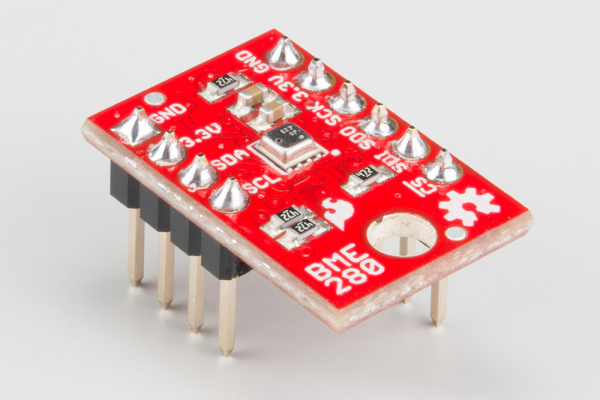
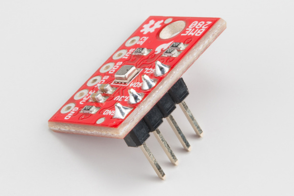
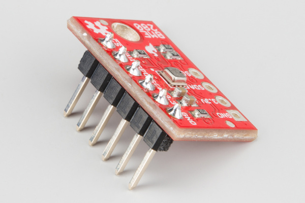
If you’re using a BME280 to try out the I2C or SPI port, install headers on it as well. See the BME280 Hookup Guide for more information.


For generic operation solder both headers (left). If you only need I2C (middle), or SPI (right), only attach those headers.

3-Pin JST and microSD Card

Make sure the JST and microSD cards are installed properly.

  • If the JST connectors feel like they’re not going in, don’t force them, try wiggling them instead. They will hang out a bit when properly seated.

  • The microSD card slot is dual position with click feature, and the PCB has a recess. The card should easily click in and out.

The JST connectors are seated properly, protruding slightly from their sockets (left). When the SD card is inserted properly (right), it should be flush with the edge of the board.

Stack and Connect Additional Parts!

Stack the ESP32 Thing on the ESP32 Thing Motion Shield.

Completed Installation

ESP32 Thing, motion shield, GPS receiver, and battery installed. The ESP32 Thing is ready for code!

You can also install the stack in a breadboard, letting the antenna hang off the end so you have the most room left to work with when prototyping. If using the BME280, install that on the breadboard as well and wire the sensor as explained in the “Using the I2C and SPI Buses” example.

Software

General Requirements

Note: This example assumes you are using the latest version of the Arduino IDE on your desktop. If this is your first time using Arduino, please review our tutorial on installing the Arduino IDE. If you have not previously installed an Arduino library, please check out our installation guide.

The Motion Shield itself doesn’t use any special software. It relies on the SD card library from the ESP32 core, and the LSM9DS1 library, plus whatever you attach to it. Make sure you’ve got the following installed before continuing on to the examples.

The example code used throughout this tutorial can also be found in the ESP32 Thing Motion Shield’s GitHub repository.

ESP32 Thing Motion Shield Example Code

General Tips

Strapping Pins

The following pins are used to configure the CPU at power up to indicate various booting methods (known as ‘strapping’ pins). These are exposed to the user, but should be avoided for beginners. Attaching a device that matches the default state during power up should not interfere with the boot procedure. If it seems like the ESP32 isn’t booting properly, investigate these pins.

ESP32 Pin NameESP32 Thing Pin NameDefault PullDescription
MTDIGPIO12HighInternal LDO voltage select
GPIO0GPIO0HighSPI/Download boot
GPIO2GPIO2LowSPI/Download boot
MTDOGPIO15HighU0TXD toggling mode/timing
GPIO5GPIO5HighU0TXD timing
GPIO4GPIO4LowUnknown

If U0TXD, GPIO2, GPIO5 are floating, GPIO0 determines boot mode.

See the ESP32 Datasheet for more information.

Input-only Pins

GPIO34 through GPIO39 work only as inputs, with no internal pull capabilities (as of 10/31/2017).

Standard pin naming

The pins listed in Hardware Overview are also listed here as #defines you can use. Not all are necessary for every application, but it’s nice to have them all in one place for reference.

language:c
#define AUX_LED_PIN 13
#define GPS_TX_PIN 16
#define GPS_RX_PIN 17
#define SD_SCK_PIN 18
#define SD_DO_PIN 19
#define SD_DI_PIN 23
#define SD_CS_PIN 33
#define SD_CD_PIN 38
#define IMU_SDA_PIN 21
#define IMU_SCL_PIN 22

Using the IMU

The IMU on the shield is the LSM9DS1, which is connected the the ESP32 Thing to the I2C port only. Any of the examples from the LSM9DS1 library should be good to go, as long as you specify the port type to be I2C with default addresses.

There are two examples in this section that will work without modification on the Motion Board.

The first example is a modification of the LSM9DS1_ESP32_Settings.ino example, with SPI related information removed. This is a good place to start because it shows all of the API, and you can comment out what you don’t need.

language:c
/*****************************************************************
LSM9DS1_ESP32_Settings.ino
SFE_LSM9DS1 Library Settings Configuration Example
Original Creation: August 13, 2015 by Jim Lindblom
https://github.com/sparkfun/LSM9DS1_Breakout

This Arduino sketch demonstrates how to configure every
possible configuration value in the SparkFunLSM9DS1 library.

It demonstrates how to set the output data rates and scales
for each sensor, along with other settings like LPF cutoff
frequencies and low-power settings.

It also demonstrates how to turn various sensors in the
LSM9DS1 on or off.

Hardware setup: This library is intended to be used with a
ESP32 Motion shield connected directly to the ESP32 Thing.

Development environment specifics:
IDE: Arduino 1.8.2
Hardware Platform: ESP32 Arduion Board

This code is beerware. If you see me (or any other SparkFun
employee) at the local, and you've found our code helpful,
please buy us a round!

Distributed as-is; no warranty is given.
*****************************************************************/
// Include SparkFunLSM9DS1 library and its dependencies
#include <Wire.h>
#include <SPI.h>
#include <SparkFunLSM9DS1.h>

LSM9DS1 imu;  // Create an LSM9DS1 object

// Mag address must be 0x1E, would be 0x1C if SDO_M is LOW
#define LSM9DS1_M   0x1E
// Accel/gyro address must be 0x6B, would be 0x6A if SDO_AG is LOW
#define LSM9DS1_AG  0x6B

// Global variables to keep track of update rates
unsigned long startTime;
unsigned int accelReadCounter = 0;
unsigned int gyroReadCounter = 0;
unsigned int magReadCounter = 0;
unsigned int tempReadCounter = 0;

// Global variables to print to serial monitor at a steady rate
unsigned long lastPrint = 0;
const unsigned int PRINT_RATE = 500;

void setupDevice()
{
// Use IMU_MODE_I2C
imu.settings.device.commInterface = IMU_MODE_I2C;
imu.settings.device.mAddress = LSM9DS1_M;
imu.settings.device.agAddress = LSM9DS1_AG;
}

void setupGyro()
{
// [enabled] turns the gyro on or off.
imu.settings.gyro.enabled = true;  // Enable the gyro
// [scale] sets the full-scale range of the gyroscope.
// scale can be set to either 245, 500, or 2000
imu.settings.gyro.scale = 245; // Set scale to +/-245dps
// [sampleRate] sets the output data rate (ODR) of the gyro
// sampleRate can be set between 1-6
// 1 = 14.9    4 = 238
// 2 = 59.5    5 = 476
// 3 = 119     6 = 952
imu.settings.gyro.sampleRate = 3; // 59.5Hz ODR
// [bandwidth] can set the cutoff frequency of the gyro.
// Allowed values: 0-3. Actual value of cutoff frequency
// depends on the sample rate. (Datasheet section 7.12)
imu.settings.gyro.bandwidth = 0;
// [lowPowerEnable] turns low-power mode on or off.
imu.settings.gyro.lowPowerEnable = false; // LP mode off
// [HPFEnable] enables or disables the high-pass filter
imu.settings.gyro.HPFEnable = true; // HPF disabled
// [HPFCutoff] sets the HPF cutoff frequency (if enabled)
// Allowable values are 0-9. Value depends on ODR.
// (Datasheet section 7.14)
imu.settings.gyro.HPFCutoff = 1; // HPF cutoff = 4Hz
// [flipX], [flipY], and [flipZ] are booleans that can
// automatically switch the positive/negative orientation
// of the three gyro axes.
imu.settings.gyro.flipX = false; // Don't flip X
imu.settings.gyro.flipY = false; // Don't flip Y
imu.settings.gyro.flipZ = false; // Don't flip Z
}

void setupAccel()
{
// [enabled] turns the acclerometer on or off.
imu.settings.accel.enabled = true; // Enable accelerometer
// [enableX], [enableY], and [enableZ] can turn on or off
// select axes of the acclerometer.
imu.settings.accel.enableX = true; // Enable X
imu.settings.accel.enableY = true; // Enable Y
imu.settings.accel.enableZ = true; // Enable Z
// [scale] sets the full-scale range of the accelerometer.
// accel scale can be 2, 4, 8, or 16
imu.settings.accel.scale = 8; // Set accel scale to +/-8g.
// [sampleRate] sets the output data rate (ODR) of the
// accelerometer. ONLY APPLICABLE WHEN THE GYROSCOPE IS
// DISABLED! Otherwise accel sample rate = gyro sample rate.
// accel sample rate can be 1-6
// 1 = 10 Hz    4 = 238 Hz
// 2 = 50 Hz    5 = 476 Hz
// 3 = 119 Hz   6 = 952 Hz
imu.settings.accel.sampleRate = 1; // Set accel to 10Hz.
// [bandwidth] sets the anti-aliasing filter bandwidth.
// Accel cutoff freqeuncy can be any value between -1 - 3.
// -1 = bandwidth determined by sample rate
// 0 = 408 Hz   2 = 105 Hz
// 1 = 211 Hz   3 = 50 Hz
imu.settings.accel.bandwidth = 0; // BW = 408Hz
// [highResEnable] enables or disables high resolution
// mode for the acclerometer.
imu.settings.accel.highResEnable = false; // Disable HR
// [highResBandwidth] sets the LP cutoff frequency of
// the accelerometer if it's in high-res mode.
// can be any value between 0-3
// LP cutoff is set to a factor of sample rate
// 0 = ODR/50    2 = ODR/9
// 1 = ODR/100   3 = ODR/400
imu.settings.accel.highResBandwidth = 0;
}

void setupMag()
{
// [enabled] turns the magnetometer on or off.
imu.settings.mag.enabled = true; // Enable magnetometer
// [scale] sets the full-scale range of the magnetometer
// mag scale can be 4, 8, 12, or 16
imu.settings.mag.scale = 12; // Set mag scale to +/-12 Gs
// [sampleRate] sets the output data rate (ODR) of the
// magnetometer.
// mag data rate can be 0-7:
// 0 = 0.625 Hz  4 = 10 Hz
// 1 = 1.25 Hz   5 = 20 Hz
// 2 = 2.5 Hz    6 = 40 Hz
// 3 = 5 Hz      7 = 80 Hz
imu.settings.mag.sampleRate = 5; // Set OD rate to 20Hz
// [tempCompensationEnable] enables or disables
// temperature compensation of the magnetometer.
imu.settings.mag.tempCompensationEnable = false;
// [XYPerformance] sets the x and y-axis performance of the
// magnetometer to either:
// 0 = Low power mode      2 = high performance
// 1 = medium performance  3 = ultra-high performance
imu.settings.mag.XYPerformance = 3; // Ultra-high perform.
// [ZPerformance] does the same thing, but only for the z
imu.settings.mag.ZPerformance = 3; // Ultra-high perform.
// [lowPowerEnable] enables or disables low power mode in
// the magnetometer.
imu.settings.mag.lowPowerEnable = false;
// [operatingMode] sets the operating mode of the
// magnetometer. operatingMode can be 0-2:
// 0 = continuous conversion
// 1 = single-conversion
// 2 = power down
imu.settings.mag.operatingMode = 0; // Continuous mode
}

void setupTemperature()
{
// [enabled] turns the temperature sensor on or off.
imu.settings.temp.enabled = true;
}

uint16_t initLSM9DS1()
{
setupDevice(); // Setup general device parameters
setupGyro(); // Set up gyroscope parameters
setupAccel(); // Set up accelerometer parameters
setupMag(); // Set up magnetometer parameters
setupTemperature(); // Set up temp sensor parameter

return imu.begin();
}

void setup()
{
Serial.begin(115200);

Serial.println("Initializing the LSM9DS1");
uint16_t status = initLSM9DS1();
Serial.print("LSM9DS1 WHO_AM_I's returned: 0x");
Serial.println(status, HEX);
Serial.println("Should be 0x683D");
Serial.println();

startTime = millis();
}

void loop()
{
// imu.accelAvailable() returns 1 if new accelerometer
// data is ready to be read. 0 otherwise.
if (imu.accelAvailable())
{
    imu.readAccel();
    accelReadCounter++;
}

// imu.gyroAvailable() returns 1 if new gyroscope
// data is ready to be read. 0 otherwise.
if (imu.gyroAvailable())
{
    imu.readGyro();
    gyroReadCounter++;
}

// imu.magAvailable() returns 1 if new magnetometer
// data is ready to be read. 0 otherwise.
if (imu.magAvailable())
{
    imu.readMag();
    magReadCounter++;
}

// imu.tempAvailable() returns 1 if new temperature sensor
// data is ready to be read. 0 otherwise.
if (imu.tempAvailable())
{
    imu.readTemp();
    tempReadCounter++;
}

// Every PRINT_RATE milliseconds, print sensor data:
if ((lastPrint + PRINT_RATE) < millis())
{
    printSensorReadings();
    lastPrint = millis();
}
}

// printSensorReadings prints the latest IMU readings
// along with a calculated update rate.
void printSensorReadings()
{
float runTime = (float)(millis() - startTime) / 1000.0;
float accelRate = (float)accelReadCounter / runTime;
float gyroRate = (float)gyroReadCounter / runTime;
float magRate = (float)magReadCounter / runTime;
float tempRate = (float)tempReadCounter / runTime;
Serial.print("A: ");
Serial.print(imu.calcAccel(imu.ax));
Serial.print(", ");
Serial.print(imu.calcAccel(imu.ay));
Serial.print(", ");
Serial.print(imu.calcAccel(imu.az));
Serial.print(" g \t| ");
Serial.print(accelRate);
Serial.println(" Hz");
Serial.print("G: ");
Serial.print(imu.calcGyro(imu.gx));
Serial.print(", ");
Serial.print(imu.calcGyro(imu.gy));
Serial.print(", ");
Serial.print(imu.calcGyro(imu.gz));
Serial.print(" dps \t| ");
Serial.print(gyroRate);
Serial.println(" Hz");
Serial.print("M: ");
Serial.print(imu.calcMag(imu.mx));
Serial.print(", ");
Serial.print(imu.calcMag(imu.my));
Serial.print(", ");
Serial.print(imu.calcMag(imu.mz));
Serial.print(" Gs \t| ");
Serial.print(magRate);
Serial.println(" Hz");
Serial.print("T: ");
Serial.print(imu.temperature);
Serial.print(" \t\t\t| ");
Serial.print(tempRate);
Serial.println(" Hz");
Serial.println();
}

The second example is more heavily modified example. It outputs CSV data to the serial port (which can be rerouted to a file if you’re into that). Here, a simple configuration is chosen but more work is done with the output data.

language:c
/*****************************************************************
LSM9DS1_CSV.ino
Collecting IMU data as CSV for graphing

Original Creation: August 13, 2015 by Jim Lindblom
from the LSM9DS1_Basic_I2C.ino library example.
https://github.com/sparkfun/LSM9DS1_Breakout

Hardware setup: This library is intended to be used with a
ESP32 Motion shield connected directly to the ESP32 Thing.

Development environment specifics:
IDE: Arduino 1.8.2
Hardware Platform: ESP32 Arduion Board

This code is beerware. If you see me (or any other SparkFun
employee) at the local, and you've found our code helpful,
please buy us a round!

Distributed as-is; no warranty is given.
*****************************************************************/
// The SFE_LSM9DS1 library requires both Wire and SPI be
// included BEFORE including the 9DS1 library.
#include <Wire.h>
#include <SPI.h>
#include <SparkFunLSM9DS1.h>

LSM9DS1 imu;  // Create an LSM9DS1 object

#define LSM9DS1_M   0x1E // Would be 0x1C if SDO_M is LOW
#define LSM9DS1_AG  0x6B // Would be 0x6A if SDO_AG is LOW

#define PRINT_SPEED 250 // 250 ms between prints
static unsigned long lastPrint = 0; // Keep track of print time

// Earth's magnetic field varies by location. Add or subtract
// a declination to get a more accurate heading. Calculate
// your's here:
// http://www.ngdc.noaa.gov/geomag-web/#declination
#define DECLINATION -8.58 // Declination (degrees) in Boulder, CO.

//Internal variables
float roll;
float pitch;
float heading;
char csvBuffer[300];

void setup()
{
Serial.begin(115200);

// Configure LSM9DS1 library parameters
imu.settings.device.commInterface = IMU_MODE_I2C;
imu.settings.device.mAddress = LSM9DS1_M;
imu.settings.device.agAddress = LSM9DS1_AG;
imu.settings.mag.scale = 2;
// The above lines will only take effect AFTER calling
// imu.begin(), which verifies communication with the IMU
// and turns it on.


delay(1000);
Serial.println("Starting Sketch");

delay(100);
if (!imu.begin())
{
    Serial.println("Failed to communicate with LSM9DS1.");
    Serial.println("Double-check connections.");
    while (1)
    ;
}

}

void loop()
{
// Update the sensor values whenever new data is available
if ( imu.gyroAvailable() )
{
    // To read from the gyroscope,  first call the
    // readGyro() function. When it exits, it'll update the
    // gx, gy, and gz variables with the most current data.
    imu.readGyro();
}
if ( imu.accelAvailable() )
{
    // To read from the accelerometer, first call the
    // readAccel() function. When it exits, it'll update the
    // ax, ay, and az variables with the most current data.
    imu.readAccel();
}
if ( imu.magAvailable() )
{
    // To read from the magnetometer, first call the
    // readMag() function. When it exits, it'll update the
    // mx, my, and mz variables with the most current data.
    imu.readMag();
}

if ((lastPrint + PRINT_SPEED) < millis())
{
    // Print the collected data as CSV
    calcAttitude(imu.ax, imu.ay, imu.az, -imu.my, -imu.mx, imu.mz);
    float data1 = imu.calcGyro(imu.gx);
    float data2 = imu.calcGyro(imu.gy);
    float data3 = imu.calcGyro(imu.gz);
    float data4 = imu.calcAccel(imu.ax);
    float data5 = imu.calcAccel(imu.ay);
    float data6 = imu.calcAccel(imu.az);
    float data7 = imu.calcMag(imu.mx);
    float data8 = imu.calcMag(imu.my);
    float data9 = imu.calcMag(imu.mz);

    sprintf(csvBuffer, "%4.3f,%4.3f,%4.3f,%4.3f,%4.3f,%4.3f,%4.3f,%4.3f,%4.3f,%4.3f,%4.3f,%4.3f,", data1, data2, data3, data4, data5, data6, data7, data8, data9, roll, pitch, heading);
    Serial.print(csvBuffer);
    Serial.println();

    lastPrint = millis(); // Update lastPrint time
}
}

void calcAttitude(float ax, float ay, float az, float mx, float my, float mz)
{
roll = atan2(ay, az);
pitch = atan2(-ax, sqrt(ay * ay + az * az));
heading;

if (my == 0)
    heading = (mx < 0) ? PI : 0;
else
    heading = atan2(mx, my);

heading -= DECLINATION * PI / 180;

if (heading > PI) heading -= (2 * PI);
else if (heading < -PI) heading += (2 * PI);
else if (heading < 0) heading += 2 * PI;

// Convert everything from radians to degrees:
heading *= 180.0 / PI;
pitch *= 180.0 / PI;
roll  *= 180.0 / PI;
}

Using the MicroSD Card

The microSD card relies on the libraries packaged with the ESP32 Arduino board files. The best way to garner knowledge is to go into the source files and read the various header files, or to use the example sketches.

To use the examples directly, make sure you assign the CS pin to 33.

This example also shows how to setup the CD pin as input, and to us it to detect a card. The program will halt during setup if a card is not detected, or if the card doesn’t mount properly.

If everything’s a go, the LSM9DS1_CSV.ino example will report basic information about the card.

language:c
/*****************************************************************
LSM9DS1_CSV.ino

This is a modified version of the SD_Test example sketch
included with the Arduino core for the esp32, from
https://github.com/espressif/arduino-esp32

This example:
* Uses the CD pin to check for a card
* Mounts the card
* Prints information about the card.

Use this for a starting place while working with SD cards.

Hardware requirements:
ESP32 Thing attached to Motion Board

Distributed as-is; no warranty is given.
*****************************************************************/
#include "FS.h"
#include "SD.h"
#include "SPI.h"

#define SD_CS_PIN 33
#define SD_CD_PIN 38


void setup(){
    Serial.begin(115200);

    //Check for card presence using CD pin
    pinMode(SD_CD_PIN, INPUT);
    if(digitalRead(SD_CD_PIN) == 1) {
        Serial.println("Card detected");
    } else {
        Serial.println("Card not present");
        return;
    }
    //Call begin with (cs pin, SPI, rate (up to 10MHz), "/sd")
    if(!SD.begin(SD_CS_PIN, SPI, 1000000, "/sd")){
        Serial.println("Card Mount Failed");
        return;
    }
    uint8_t cardType = SD.cardType();

    if(cardType == CARD_NONE){
        Serial.println("No SD card attached");
        return;
    }

    Serial.print("SD Card Type: ");
    if(cardType == CARD_MMC){
        Serial.println("MMC");
    } else if(cardType == CARD_SD){
        Serial.println("SDSC");
    } else if(cardType == CARD_SDHC){
        Serial.println("SDHC");
    } else {
        Serial.println("UNKNOWN");
    }

    uint64_t cardSize = SD.cardSize() / (1024 * 1024);
    Serial.printf("SD Card Size: %lluMB\n", cardSize);

}

void loop(){

}

To help with development in the FileSerialExample.ino example, I’ve written a little SD extension library that allows writing of sequentially numbered files up to a particular size. It behaves like a serial port, so things like .println() can be used.

Don't run this example! This example requires FileSerial.cpp and FileSerial.h to operate. It is here to show how similar the file writing operation of these two included files is to a normal serial object. Get the full project (this example plus code and header) from https://github.com/sparkfun/ESP32_Motion_Shield/tree/master/Software/FileSerialExample.

In addition to standard methods such as print() and println(), the library includes the following functionality.

Construction

Create a file writing object with the class name FileSerial. You can construct in two ways:

  • FileSerial ExampleFileSet(&Serial);– Verbose output of data/File IO status to passed serial object.
  • FileSerial ExampleFileSet;– Non-verbose.

begin();

int begin(fs::FS * inputDevice, uint8_t ssPin, SPIClass &spi, uint32_t frequency, const char * mountpoint);

Call begin to mount the card and start the SPI device.

Pass: device, CS pin, port, frequency, and mount point.

Returns: 1 if success.

Example:ExampleFileSet.begin(&SD, 33, SPI, 10000000, "/sd")

setMaxFileSize();

void setMaxFileSize( int32_t inputSize );

Call to set the max file size in bytes.

Default: 250kB

Range:

  • 0 – No cap.
  • 32 to 1000000000 – 32 bytes to 1GB

setWriteBufferSize();

void setWriteBufferSize( uint8_t inputSize );

Call to set buffer size in bytes before performing file write.

Default: 100B

Range: 1 to 255 – 1B to 255B

startLog()

int startLog( const char * inputPath, const char * inputStub );

Start a batch of log files. Pass directory name and file name. The file name will be appended with nnnn.txt where “nnnn” are sequential numbers.

If directory is a path, parent directories must exist!

  • “[existing directory]/[new directory]” is valid
  • “[new directory]/[new directory]” is not

Example:ExampleFileSet.startLog("testFiles", "file");

language:c
/******************************************************************************
FileSerialExample.ino
Example Serial-like file writer

Marshall Taylor @ SparkFun Electronics
original creation date: Nov 6, 2017
https://github.com/sparkfun/ESP32_Motion_Shield

This example demonstrates usage of the FileSerial library.

The FileSerial libary implements the ESP32 SD_Test functions as a class that acts like a
HardwareSerial device.  It has been modeled from the ESP32 Arduino core's
HardwareSerial class, but takes no input streams from the user.

There are a couple extra functions that aren't normally found in a serial device

    int startLog( const char * inputPath, const char * inputStub );
    int stopLog( void );
    void setMaxFileSize( int32_t inputSize );
    void setWriteBufferSize( uint8_t inputSize );

Construct with an optional serial device address, such as

    FileSerial ExampleFileSet(&Serial);

Doing so logs SD read/write information plus written data to the passed serial port.

Resources:
ESP32 Arduino core

Development environment specifics:
Arduino 1.8.2

This code is released under the [MIT License](http://opensource.org/licenses/MIT).
Please review the LICENSE.md file included with this example. If you have any questions
or concerns with licensing, please contact techsupport@sparkfun.com.
Distributed as-is; no warranty is given.
******************************************************************************/

#include <Arduino.h>
#include "FileSerial.h"

//Pass address of serial port to see the file IO debug information
FileSerial ExampleFileSet(&Serial);

//...or don't
//FileSerial ExampleFileSet;

int loopCount = 0;

void setup(){
    Serial.begin(115200);

    delay(1000);
    Serial.println("Starting Sketch");

    //call begin with device, CS pin, port, frequency, and mount point.
    if(ExampleFileSet.begin(&SD, 33, SPI, 10000000, "/sd") == 0)
    {
        Serial.println("SD begin did not succeed, halting.");
        while(1);
    }
    //File name will be appended with file number, ex: filennnn.txt

    //You can set max file size in bytes, set 0 for unchecked.
    //Default is 250kB, range 0, 32 to 1000000000
    ExampleFileSet.setMaxFileSize(10000);

    //You can as set buffer size between file writes.
    //Default is 100B, range is 1 to 255B
    ExampleFileSet.setWriteBufferSize(80);

    //Start a batch of log files with startLog,
    //pass directory name and file name.
    //
    //If directoy is path, parent directories must exist!
    //"[existing directory]/[new directory]" is valid
    //"[new directory]/[new directory]" is not
    ExampleFileSet.startLog("testFiles", "file");
}

void loop(){
    while(Serial.available())
    {
        char c = Serial.read();
        ExampleFileSet.print(c);
    }
    ExampleFileSet.printf("Loop count: %d\n", loopCount); //Formatting works
    ExampleFileSet.println(2.54321, 3); //standard formatting works
    ExampleFileSet.println(0x2E0A, HEX); //and other types
    loopCount++;
    delay(100);

}

Using the I2C and SPI Buses

To demonstrate the attachment of additional I2C and SPI devices, a BME280 is used. This could be any device, but the BME280 has both ports and is pretty easy to work with. There is one catch though, the SPI bus is shared with the microSD card and it will limit in the microSD card’s data rate to the lowest common speed.

The two examples show are actually the same program, but with two lines which are configured for either I2C or SPI mode.

I2C

Hookup the I2C pins between the BME280 and the ESP32 Thing as shown below.

BME280 and I2C Example

Connect the BME280 I2C port

To connect the BME280 to the ESP32, wire up as follows:

BME280 Pin
ESP32 Pin
SCL22
SDA21
3.3V3.3V
GNDGND

Then, run the following example.

language:c
/******************************************************************************
BME280_I2C_SPI.ino
BME280 on the ESP32 Thing

Marshall Taylor @ SparkFun Electronics
Original creation date: May 20, 2015
Modified: Nov 6, 2017
https://github.com/sparkfun/ESP32_Motion_Shield

This sketch configures a BME280 to produce comma separated values for use
in generating spreadsheet graphs.

It has been modified from the original BME280 example to demonstrate I2C and
SPI operation on the ESP32 Motion board.

Original source:
https://github.com/sparkfun/SparkFun_BME280_Arduino_Library

Resources:
Uses Wire.h for I2C operation
Uses SPI.h for SPI operation

Development environment specifics:
Arduino IDE 1.8.2

This code is released under the [MIT License](http://opensource.org/licenses/MIT).
Please review the LICENSE.md file included with this example. If you have any questions
or concerns with licensing, please contact techsupport@sparkfun.com.
Distributed as-is; no warranty is given.
******************************************************************************/
#include <stdint.h>
#include "SparkFunBME280.h"

#include "Wire.h"
#include "SPI.h"

#define BME280_CS_PIN 17

//Global sensor object
BME280 mySensor;

unsigned int sampleNumber = 0; //For counting number of CSV rows

void setup()
{
    //***Driver settings********************************//
    //  commInterface can be I2C_MODE or SPI_MODE.

    //For I2C, enable the following and disable the SPI section.
    //I2CAddress can be 0x77(default) or 0x76.
    mySensor.settings.commInterface = I2C_MODE;
    mySensor.settings.I2CAddress = 0x77;

    //For SPI enable the following and dissable the I2C section.
    //set chipSelectPin using arduino pin names.
    //mySensor.settings.commInterface = SPI_MODE;
    //mySensor.settings.chipSelectPin = BME280_CS_PIN;


    //***Operation settings*****************************//
    mySensor.settings.runMode = 3; //  3, Normal mode
    mySensor.settings.tStandby = 0; //  0, 0.5ms
    mySensor.settings.filter = 0; //  0, filter off
    //tempOverSample can be:
    //  0, skipped
    //  1 through 5, oversampling *1, *2, *4, *8, *16 respectively
    mySensor.settings.tempOverSample = 1;
    //pressOverSample can be:
    //  0, skipped
    //  1 through 5, oversampling *1, *2, *4, *8, *16 respectively
    mySensor.settings.pressOverSample = 1;
    //humidOverSample can be:
    //  0, skipped
    //  1 through 5, oversampling *1, *2, *4, *8, *16 respectively
    mySensor.settings.humidOverSample = 1;

    Serial.begin(115200);
    Serial.print("Program Started\n");
    Serial.print("Starting BME280... result of .begin(): 0x");
    delay(10);  //Make sure sensor had enough time to turn on. BME280 requires 2ms to start up.
    //Calling .begin() causes the settings to be loaded
    Serial.println(mySensor.begin(), HEX);

    //Build a first-row of column headers
    Serial.print("\n\n");
    Serial.print("Sample,");
    Serial.print("T(deg C),");
    Serial.print("T(deg F),");
    Serial.print("P(Pa),");
    Serial.print("Alt(m),");
    Serial.print("Alt(ft),");
    Serial.print("%RH");
    Serial.println("");

}

void loop()
{

    //Print each row in the loop
    //Start with temperature, as that data is needed for accurate compensation.
    //Reading the temperature updates the compensators of the other functions
    //in the background.
    Serial.print(sampleNumber);
    Serial.print(",");
    Serial.print(mySensor.readTempC(), 2);
    Serial.print(",");
    Serial.print(mySensor.readTempF(), 3);
    Serial.print(",");
    Serial.print(mySensor.readFloatPressure(), 0);
    Serial.print(",");
    Serial.print(mySensor.readFloatAltitudeMeters(), 3);
    Serial.print(",");
    Serial.print(mySensor.readFloatAltitudeFeet(), 3);
    Serial.print(",");
    Serial.print(mySensor.readFloatHumidity(), 0);
    Serial.println();

    sampleNumber++;

    delay(50);

}

SPI

SPI Data Rate: The SPI port is shared with the microSD card. The Arduino Board for the ESP32 doesn't allow multiple data rates, so when using the SPI port for your own peripherals, the SD data rate will be constrained to the lowest common speed capability.

Now wire the BME280 up to the ESP32’s SPI port.

BME280 and SPI Example

Connect the BME280 SPI port

Here are the connections in the picture.

BME280 Pin
ESP32 Pin
CS17
SDI
23
SDO19
SCK
18
3.3V3.3V
GNDGND

To start the BME280 in SPI mode, switch the configuration by commenting/uncommenting code. Otherwise, the code is the same.

language:c
/******************************************************************************
BME280_I2C_SPI.ino
BME280 on the ESP32 Thing

Marshall Taylor @ SparkFun Electronics
Original creation date: May 20, 2015
Modified: Nov 6, 2017
https://github.com/sparkfun/ESP32_Motion_Shield

This sketch configures a BME280 to produce comma separated values for use
in generating spreadsheet graphs.

It has been modified from the original BME280 example to demonstrate I2C and
SPI operation on the ESP32 Motion board.

Original source:
https://github.com/sparkfun/SparkFun_BME280_Arduino_Library

Resources:
Uses Wire.h for I2C operation
Uses SPI.h for SPI operation

Development environment specifics:
Arduino IDE 1.8.2

This code is released under the [MIT License](http://opensource.org/licenses/MIT).
Please review the LICENSE.md file included with this example. If you have any questions
or concerns with licensing, please contact techsupport@sparkfun.com.
Distributed as-is; no warranty is given.
******************************************************************************/
#include <stdint.h>
#include "SparkFunBME280.h"

#include "Wire.h"
#include "SPI.h"

#define BME280_CS_PIN 17

//Global sensor object
BME280 mySensor;

unsigned int sampleNumber = 0; //For counting number of CSV rows

void setup()
{
    //***Driver settings********************************//
    //  commInterface can be I2C_MODE or SPI_MODE.

    //For I2C, enable the following and disable the SPI section.
    //I2CAddress can be 0x77(default) or 0x76.
    //mySensor.settings.commInterface = I2C_MODE;
    //mySensor.settings.I2CAddress = 0x77;

    //For SPI enable the following and dissable the I2C section.
    //set chipSelectPin using arduino pin names.
    mySensor.settings.commInterface = SPI_MODE;
    mySensor.settings.chipSelectPin = BME280_CS_PIN;


    //***Operation settings*****************************//
    mySensor.settings.runMode = 3; //  3, Normal mode
    mySensor.settings.tStandby = 0; //  0, 0.5ms
    mySensor.settings.filter = 0; //  0, filter off
    //tempOverSample can be:
    //  0, skipped
    //  1 through 5, oversampling *1, *2, *4, *8, *16 respectively
    mySensor.settings.tempOverSample = 1;
    //pressOverSample can be:
    //  0, skipped
    //  1 through 5, oversampling *1, *2, *4, *8, *16 respectively
    mySensor.settings.pressOverSample = 1;
    //humidOverSample can be:
    //  0, skipped
    //  1 through 5, oversampling *1, *2, *4, *8, *16 respectively
    mySensor.settings.humidOverSample = 1;

    Serial.begin(115200);
    Serial.print("Program Started\n");
    Serial.print("Starting BME280... result of .begin(): 0x");
    delay(10);  //Make sure sensor had enough time to turn on. BME280 requires 2ms to start up.
    //Calling .begin() causes the settings to be loaded
    Serial.println(mySensor.begin(), HEX);

    //Build a first-row of column headers
    Serial.print("\n\n");
    Serial.print("Sample,");
    Serial.print("T(deg C),");
    Serial.print("T(deg F),");
    Serial.print("P(Pa),");
    Serial.print("Alt(m),");
    Serial.print("Alt(ft),");
    Serial.print("%RH");
    Serial.println("");

}

void loop()
{

    //Print each row in the loop
    //Start with temperature, as that data is needed for accurate compensation.
    //Reading the temperature updates the compensators of the other functions
    //in the background.
    Serial.print(sampleNumber);
    Serial.print(",");
    Serial.print(mySensor.readTempC(), 2);
    Serial.print(",");
    Serial.print(mySensor.readTempF(), 3);
    Serial.print(",");
    Serial.print(mySensor.readFloatPressure(), 0);
    Serial.print(",");
    Serial.print(mySensor.readFloatAltitudeMeters(), 3);
    Serial.print(",");
    Serial.print(mySensor.readFloatAltitudeFeet(), 3);
    Serial.print(",");
    Serial.print(mySensor.readFloatHumidity(), 0);
    Serial.println();

    sampleNumber++;

    delay(50);

}

Using the GPS Port

The GPS port is just a pass-through to the serial port, so configuration is easy. Simply start the serial port at the desired baud, usually 9600.

This example simply passes serial monitor data to the GPS port, and GPS data to the serial monitor. Set the serial speeds when calling begin. Serial is the USB serial port, and Serial1 is the GPS port.

language:c
#include <Arduino.h>
HardwareSerial Serial1(2);  // UART1/Serial1 pins 16,17

void setup()
{
  Serial.begin(115200);
  Serial1.begin(9600);
  delay(1000);
  Serial.println("Weeee!");
}

void loop() {
  //Pass usb data to the gps
  if (Serial.available())
  {
    Serial1.write(Serial.read());
  }
  //Pass gps data to the usb
  if (Serial1.available())
  {
    Serial.write(Serial1.read());
  }
}

Different GPS Receivers Connected to GPS port

(left) Connection to the GP-20U7. (right) Connection to the GP-735.

As for the hardware, either plug in the recommend 3-wire GPS module (rx only), or wire in a 4-wire module (that can be run from 3.3V) to the provided pin header.

The data that the GPS will emit comes in the form of NMEA messages. See the NMEA Reference Manual (PDF) for information on decoding.

Logging a Journey

Putting all the concepts from this hookup guide together, a data logger can be built that saves IMU and GPS data. For your consideration, a simple example exists in the software folder of the Motion Shield’s GitHub repository.

ESP32_Motion_Shield / Software / GPS_IMU_SD_Logger

The program collects the GPS data as strings of NMEA data, and the IMU data as CSV. It uses the FileSerial library to create two sets of files, one for GPS data and one for IMU data. What to do with the data is up to you, but let’s take a look at the GPS data and graph it.

This is what the GPS NMEA messages look like:

The data is given to a tool such as the GPS Visualizer, which can create various types of data. Outputting as GPX format, the data can be passed to a map web application.

And finally, the GPS track can be viewed.

Example Data Logged on a Map

Taking a trip from Denver to SparkFun. Example data logged and mapped with the GPS Visualizer on Google Maps.

GPS Visualizer can also produce data that can be used in Google Earth, and has a bunch of options. If you’ve never used GPS data before, it can be super helpful to demystify all the terminology.

Resources and Going Further

Now that you’ve explored all the aspects of the Motion Shield, it’s time to duct tape the Thing to your cat to see just where they really go at night. I hope you don’t really do that, but if you wanted to, these links may help you get closer to your goal.

For more information, check out the resources below:

Need some inspiration for your next project? Check out some of these related tutorials:

GPS Mouse - GP-808G Hookup Guide

Get started with the GP-808G GPS Mouse. This GPS module is great for advanced projects such as autonomous vehicles.

Building an Autonomous Vehicle: The Batmobile

Documenting a six-month project to race autonomous Power Wheels at the SparkFun Autonomous Vehicle Competition (AVC) in 2016.

Getting Started with the GeoFence

How to get started using the GeoFence GPS Boundary Widget and GeoFence Software.
New!

SparkFun GPS Breakout - XA1110 (Qwiic) Hookup Guide

Figure out where in the world you are with the Qwiic SparkFun GPS Breakout - XA1110.

learn.sparkfun.com |CC BY-SA 3.0 | SparkFun Electronics | Niwot, Colorado

LilyPad Safety Scarf

$
0
0

LilyPad Safety Scarf a learn.sparkfun.com tutorial

Available online at: http://sfe.io/t712

Introduction

Design and build time: 1 Day

In this project, we’ll create a wearable safety scarf The safety scarf is embedded with LilyPad Hardware and a ribbon of LEDs. It is designed for pedestrians to increase visibility when walking the streets at night. The LED ribbon is triggered when light is low, making the wearer more visible to vehicles, bikers, and other pedestrians.

safety scarf

Suggested Reading

Before you get started, take some time to familiarize yourself with the following:

How to Solder: Through-Hole Soldering

This tutorial covers everything you need to know about through-hole soldering.

Working with Wire

How to strip, crimp and work with wire.

Light-Emitting Diodes (LEDs)

Learn the basics about LEDs as well as some more advanced topics to help you calculate requirements for projects containing many LEDs.

Polarity

An introduction to polarity in electronic components. Discover what polarity is, which parts have it, and how to identify it.

Insulation Techniques for e-Textiles

Learn a few different ways to protect your conductive thread and LilyPad components in your next wearables project.

Planning a Wearable Electronics Project

Tips and tricks for brainstorming and creating a wearables project.

LilyPad Basics: E-Sewing

Learn how to use conductive thread with LilyPad components.

LilyPad ProtoSnap Plus Hookup Guide

The LilyPad ProtoSnap Plus is a sewable electronics prototyping board that you can use to learn circuits and programming with Arduino, then break apart to make an interactive fabric or wearable project.
New!

Getting Started with LilyPad

An introduction to the LilyPad ecosystem - a set of sewable electronic pieces designed to help you build soft, sewable, interactive e-textile projects.

In this project, we will also be following a free sewing pattern from Purl Soho which can be found here.

Materials and Tools

Let’s go over all of the things you’ll need to put your project together.

Heads up! Take note that in the wishlist below we have included both the LilyPad Protosnap Plus and a seperate LilyPad light sensor. While a light sensor is included in the LilyPad ProtoSnap Plus, the anode and cathode footprints are flipped. The individual LilyPad Light Sensor works best with the microcontroller included with the LilyPad ProtoSnap Plus for this specific design. If you prefer to use the included light sensor, you will need to criss-cross the sewing traces. You can learn more about e-sewing techniques here.

You Will Also Need:

Understanding Your Circuit

The LilyPad Safety Scarf is an example of a sewable embedded circuit. For this project, we will use a LilyPad USB Plus from the LilyPad ProtoSnap Plus and LilyPad Light Sensor as well as two LED Ribbons. This project will be powered with an 850 mAh LiPo battery.

As expressed in the circuit diagram below, the sewable microcontroller is connected to a sewable light sensor via conductive thread. The light sensor has three connections, VCC, GND, and ’S'. VCC and GND connect to ‘+’ and ‘-’, respectively. The ’S' tab should be connected to pin A2 on the microcontroller.

The LED ribbon will be handled differently. While the ribbon itself can be sewn onto a garment, the electrical leads are not sewable - just traditional wires. Luckily, the LilyPad Sew tabs are also solder friendly. So in this instance, we will solder the LED lead’s soft, flexible wire to the microcontroller. The datasheet for the LED ribbon indicates that the anode is copper colored (i.e. reddish brown) and the cathode is a silver color (i.e. metallic grey). Connect the anode to pin 11 on the LilyPad USB Plus and the cathode to the GND pin labeled ‘-’.

Heads up! The diagram below assumes you are working with the LilyPad Light Sensor that is sold individually, and not the light sensor included on the LilyPad ProtoSnap Plus board.

circuit

Having a hard time seeing the circuit? Click on the wiring diagram for a closer look.

Heads up! If you use the light sensor from the LilyPad ProtoSnap Plus, your circuit will look slightly different, with the VCC and GND leads criss-crossing, as shown in the diagram below. In this case, make sure to insulate these traces with some fabric or heat shrink to avoid shorts.

circuit 2

Having a hard time seeing the circuit? Click on the wiring diagram for a closer look.

Software Installation

Arduino IDE

The LilyPad USB Plus is programmable via the Arduino IDE. If this is your first time using Arduino, please review our tutorial on installing the Arduino IDE.

Installing Arduino IDE

March 26, 2013

A step-by-step guide to installing and testing the Arduino software on Windows, Mac, and Linux.

LilyPad USB Plus and Board Add-On

If this is your first time working with the LilyPad ProtoSnap Plus, you will need to add the board through the boards manager to your program. Please visit the LilyPad ProtSnap Plus hookup guide for detailed instructions on installing drivers and programming a LilyPad via the Arduino IDE.

Heads up! The correct selection in the boards manager is the LilyPad Prototyping Board. The LilyPad USB Arduino is an older version of this board and, if selected, will cause problems during upload.

Arduino Program

Note: This example assumes you are using the latest version of the Arduino IDE on your desktop. If this is your first time using Arduino, please review our tutorial on installing the Arduino IDE.

We have provided the code for this project below. Copy and paste it into your Arduino IDE and then upload it to your board. Make sure you have the correct board selected in the boards manager as well as the port under the port drop down.

language:c
//Melissa Felderman for SparkFun Electronics 2017

//variable for sensor pin
int sensorPin = A2;

//variable for light value
int lightValue;

//variable for LEDPin
int LEDPin = 11;

void setup()
{
    // Set sensorPin as an INPUT
    pinMode(sensorPin, INPUT);

    //set LEDPin as OUTPUT
    pinMode(LEDPin, OUTPUT);


void loop()
{

   // Get the current light level
    lightValue = analogRead(sensorPin);

    //if light level is low, turn LEDS on
    if(lightValue <= 15){
      digitalWrite(LEDPin, HIGH);

    }
    //if light is high, turn LEDs off
    else {
      digitalWrite(LEDPin, LOW);
    }


}

programming

Putting It Together

STEP 1:

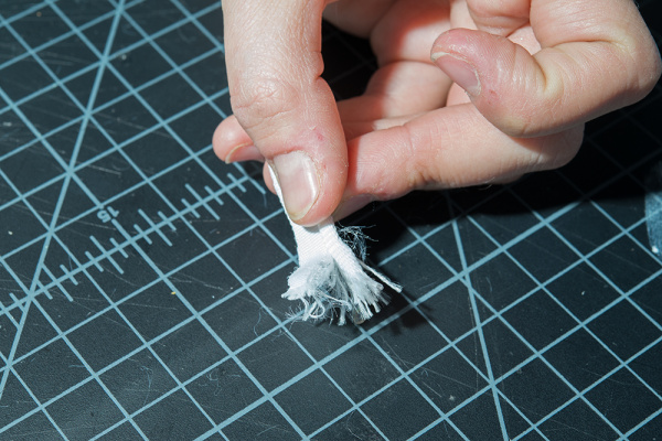
Use an X-Acto Knife to cut the fabric around the LEDs back about one inch on one side of both of your LED ribbons.

step 1

STEP 2:

This will cause the ribbon to fray at the end.

step 2

Pull back the wires and use a pair of scissors to cut off the frayed material. Make sure not to cut the LED's wires.

step 2

STEP 3:

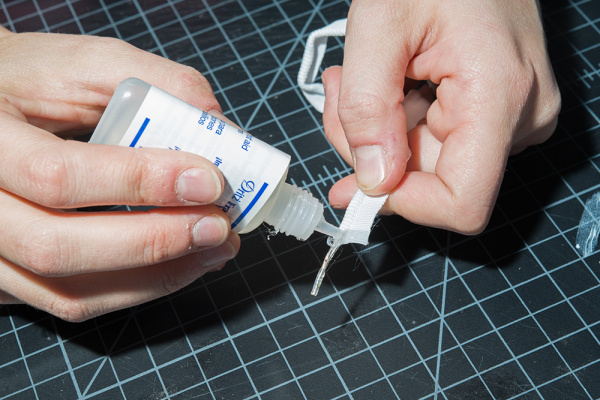
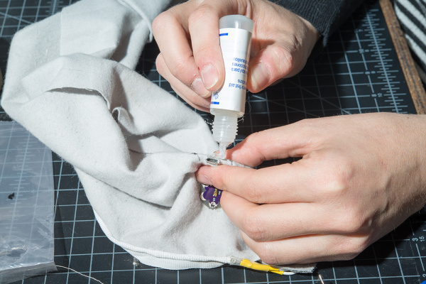
Apply Fray Check to the cut edge of each ribbon, and let it dry (~15 minutes).

step 3

STEP 4:

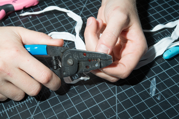
Strip the exposed wire of LED strip. Notice one lead has a copper tint and one does not. The copper tinted lead is the anode, or ‘+’ lead. For more information about polarity and LEDs, visit our tutorials about polarity and LEDs.

step 4

STEP 5:

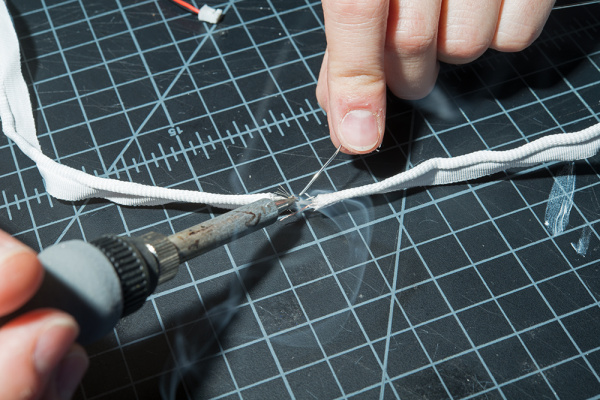
Solder the two LED ribbons together. This can be tricky with the LED ribbons since there is no room to add heat shrink and the frayed wires can easily become crossed. To battle this, I soldered my anodes first and left a little space between the two ribbons. Then, I insulated them with hot glue before soldering the cathodes together. Make sure to insulate the cathode side after soldering them together.

step 5

STEP 6:

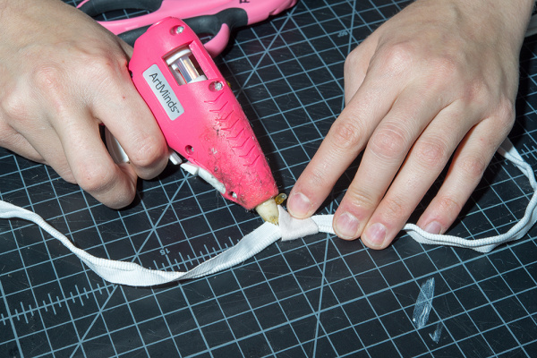
Cut a small rectangle of white felt. Fold it over the ribbon to hide the solder connections we just made. Hot glue it in place.

step 6

STEP 7:

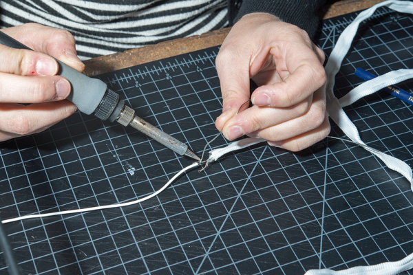
You should have one long LED ribbon now. Repeat steps 1-4 on only one end of the new long ribbon. Cut about two 4-5 inch pieces of flexible silicone wire, soldering one to the exposed anode and one to the exposed cathode.

step 7

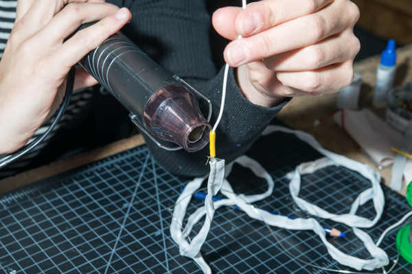
Insulate with heat shrink and then set aside for later.

step 7

STEP 8:

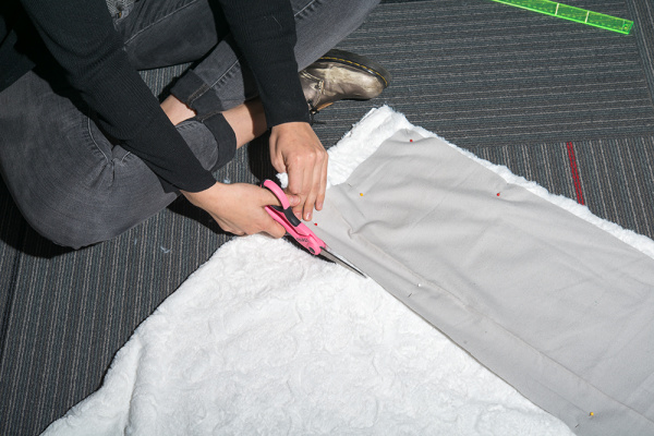
Cut your fabric according to the pattern. We used this lovely and easy to follow free cowl pattern by Purl Soho.

step 8

STEP 9:

Sew the lining pieces together. Then sew the outer pieces together, but stop before sewing the lining and the outer fabric together. Set the lining aside for later.

step 9

STEP 10:

Find the “right side” of the outer fabric. The right side is the side that will be facing the world when you wear the garment. Grab the LED ribbon, and pin it to the long edge of your outer fabric on the right side. The sew tab should be along the top edge of the fabric with the tube holding the LED strip pointing towards the center of the fabric as seen in the image below.

step 10

STEP 11:

When you reach the end of your fabric edge, cut the strip to the same length of the fabric.

step 11

STEP 12:

Add a touch of Fray Check to the edge of LED ribbon that you cut.

step 12

STEP 13:

Sew the LED ribbon down along the sew tab. Make sure to remove the pins as you go since this can break your sewing machine needle and cause problems with your stitch. When using a sewing machine, be careful to not sew into the LEDs and wires.

step 13

STEP 14:

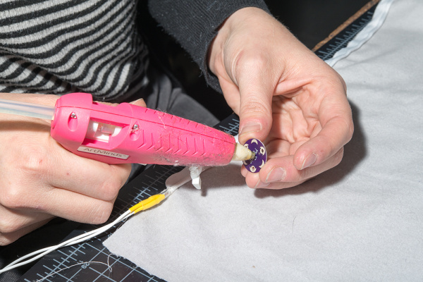
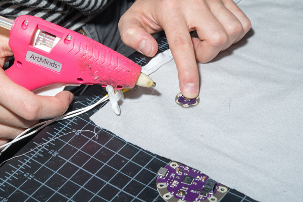
Add a dab of hot glue to the bottom of your LilyPad Light Sensor and then place it on the right side of your fabric about an inch below the LED ribbon leads.

step 14

step 14

STEP 15:

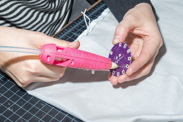
Flip the fabric over to the “wrong side.” The wrong side will be the inside of the cowl. Add some hot glue to the bottom of the LilyPad USB Plus and place it down about 1-2 inches below the light sensor (but on the opposite side!)

step 15

step 15

STEP 16:

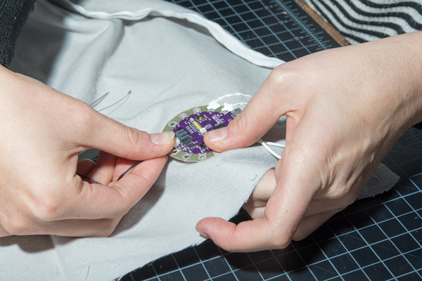
Using conductive thread, sew the light sensor to the microcontroller according to the circuit diagram.

step 16

STEP 17:

Strip the un-soldered side of both flexible silicone wires connected to the LED leads.

step 17

STEP 18:

Solder the anode (‘+’) lead connection to pin 11 on the LilyPad and the cathode (‘-’) lead to GND on the LilyPad.

step 18

STEP 19:

Cut a small hole directly above the USB cable connector. Make sure it is large enough to access that port from the opposite side of the fabric.

steo 19

step 19

STEP 20:

Apply Fray Check around the cut edges of the hole. Make sure that the Fray Check does not get into the USB connector.

step 20

STEP 21:

Trim the excess conductive thread and test your circuit with a battery. Once everything is working, use some puff paint to insulate the traces on both the right and wrong side of the fabric.

step 21

STEP 22:

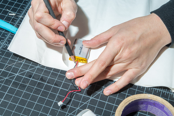
Place your battery on the iron-on adhesive and trace it.

step 22

STEP 23:

Draw a larger rectangle around the battery's trace and leave at least a half inch space between the lines.

step 23

STEP 24:

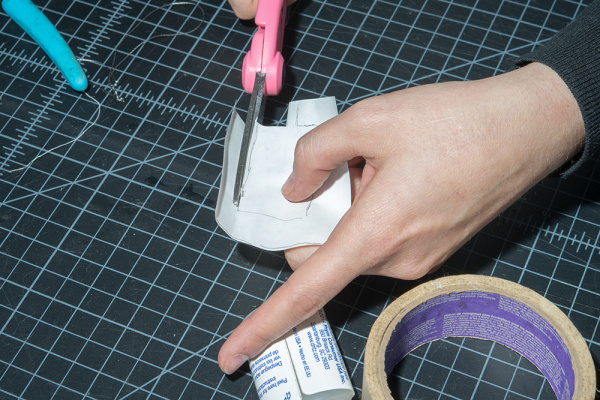
Cut along the edge of the larger rectangle, and then cut out the battery tracing as well.

step 24

step 24

STEP 25:

With the paper side up, iron the iron-on adhesive to a scrap piece of fabric. Then cut the fabric along the edge of the adhesive.

step 25

step 25

STEP 26:

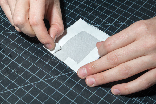
Peel the paper backing off of the iron-on adhesive.

step 26

STEP 27:

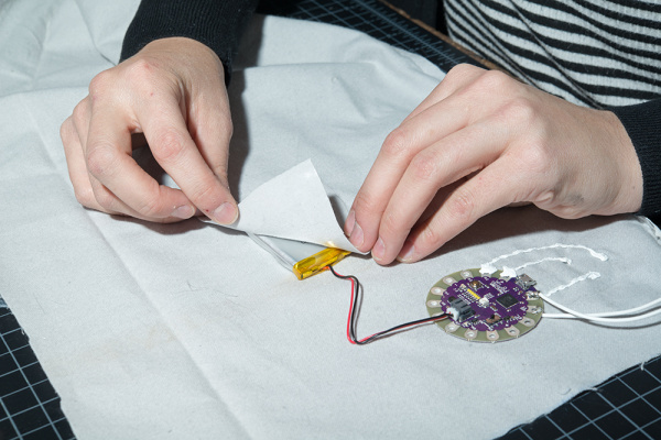
Plug your battery into the LilyPad's JST connector.

step 27

STEP 28:

Place the piece of fabric with the iron-on adhesive over of the battery. Make sure that the adhesive side is facing down.

step 28

STEP 29:

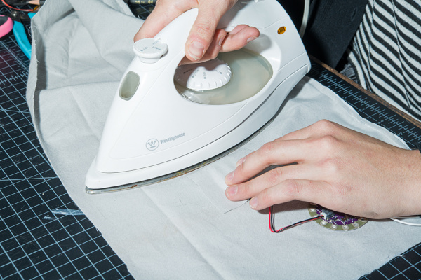
Being extremely careful to not touch the battery, and iron over the fabric where there is adhesive in order to make a battery holder.

CAUTION Heat should never be applied to directly to the battery. Use extreme caution whith the iron around the battery. If your hand is less steady, make the area around the battery larger, so you have more room between the adhesive and the battery itself. As an alternative, you can also sew the battery holder down.

step 29

STEP 30:

Finish sewing the scarf according to the pattern.

step 30

STEP 31:

Use your finger to feel for the ON/OFF switch on the LilyPad and then cut a small hole in the lining fabric to expose it.

step 31

STEP 32:

Add some Fray Check around the edge of the hole, and let dry.

step 32

STEP 33:

Turn it on by flipping the switch and enjoy!

final product

final product

final products

Resources and Going Further

Looking for another project? Check out these similar projects for inspiration!

Marquee Party Bag

This tutorial provides everything you need to know to make your own Marquee Party Bag!

Fairy LED Bracelet

Light up the world - and your wrist - with this quick and easy rechargeable firefly LED bracelet.

LED PomPom Headbands

Follow this tutorial to make your own light up PomPom headband! Try the beginner version if you are new to electronics or the advanced version if you have some more experience!

Twinkle Zodiac Constellation

Create a quick and easy piece of e-textile art based on a Zodiac sign using a LilyTiny, LilyPad LEDs, battery holder, conductive thread, and coin cell battery.

learn.sparkfun.com |CC BY-SA 3.0 | SparkFun Electronics | Niwot, Colorado
Endless Runner Game

$
0
0

Endless Runner Game a learn.sparkfun.com tutorial

Available online at: http://sfe.io/t716

Introduction

Popularized by mobile games like Temple Run, the endless running type of game is an extremely simplistic spin on the larger “platform” genre where a player has limited control over a character that is constantly moving forward. Flappy bird, while generally not considered a “running” game, was another popular infinite platform game with limited control over the character: users could only tap the screen to make the bird fly upwards in order to navigate through obstacles while constantly moving to the right.

We’re going to make our own endless runner game using an Arduino, button, and character LCD. While not as visually appealing as Temple Run or Flappy Bird, it’s almost equally as addicting.

The code for this game comes from Joshua Brooks on Instructables. The original project can be found here.

Playing the endless runner Arduino game

Required Materials

You can complete this project with parts form the SparkFun Inventor’s Kit v4.0. Specifically, you will need:

Note: If you purchase the parts separately, you will need to solder headers onto the LCD.

Suggested Reading

If you aren’t familiar with the following concepts, we recommend checking out these tutorials before continuing:

How to Solder: Through-Hole Soldering

This tutorial covers everything you need to know about through-hole soldering.

What is an Arduino?

What is this 'Arduino' thing anyway?

Installing Arduino IDE

A step-by-step guide to installing and testing the Arduino software on Windows, Mac, and Linux.
New!

SparkFun Inventor's Kit Experiment Guide - v4.0

The SparkFun Inventor's Kit (SIK) Experiment Guide contains all the information needed to build all five projects, encompassing 16 circuits, in the latest version of the kit, V4.0.

Hardware Assembly

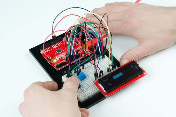
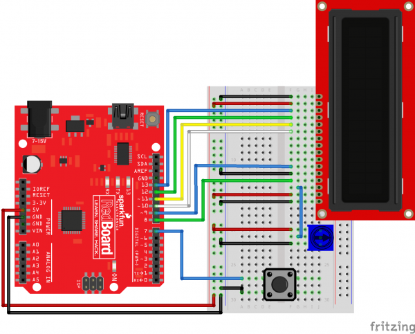
Using jumper wires, connect the components as shown in the diagram below.

SIK v4.0 Endless Runner Game

Having a hard time seeing the circuit? Click on the image for a closer look.

Programming

Note: This example assumes you are using the latest version of the Arduino IDE on your desktop. If this is your first time using Arduino, please review our tutorial on installing the Arduino IDE.

Copy and paste the following code in the Arduino IDE. Click Upload to send your compiled code to the Arduino.

language:c
/**
 * Endless Runner
 * Date: August 18, 2017
 * Author: Joshua Brooks (http://www.instructables.com/member/joshua.brooks/)
 * Modified by: Shawn Hymel (SparkFun Electronics)
 *
 * Adjust LCD contrast with the potentiometer. Press the button
 * to start the game. During gameplay, press the button to jump
 * and avoid obstacles. Running into an object will result in
 * restarting. Points are awarded based on distance.
 */

#include <LiquidCrystal.h>

// Constants
#define BTN_PIN 7

#define SPRITE_RUN1 1
#define SPRITE_RUN2 2
#define SPRITE_JUMP 3
#define SPRITE_JUMP_UPPER '.'         // Use the '.' character for the head
#define SPRITE_JUMP_LOWER 4
#define SPRITE_TERRAIN_EMPTY ' '      // User the ' ' character
#define SPRITE_TERRAIN_SOLID 5
#define SPRITE_TERRAIN_SOLID_RIGHT 6
#define SPRITE_TERRAIN_SOLID_LEFT 7

#define HERO_HORIZONTAL_POSITION 1    // Horizontal position of hero on screen

#define TERRAIN_WIDTH 16
#define TERRAIN_EMPTY 0
#define TERRAIN_LOWER_BLOCK 1
#define TERRAIN_UPPER_BLOCK 2

#define HERO_POSITION_OFF 0          // Hero is invisible
#define HERO_POSITION_RUN_LOWER_1 1  // Hero is running on lower row (pose 1)
#define HERO_POSITION_RUN_LOWER_2 2  //                              (pose 2)

#define HERO_POSITION_JUMP_1 3       // Starting a jump
#define HERO_POSITION_JUMP_2 4       // Half-way up
#define HERO_POSITION_JUMP_3 5       // Jump is on upper row
#define HERO_POSITION_JUMP_4 6       // Jump is on upper row
#define HERO_POSITION_JUMP_5 7       // Jump is on upper row
#define HERO_POSITION_JUMP_6 8       // Jump is on upper row
#define HERO_POSITION_JUMP_7 9       // Half-way down
#define HERO_POSITION_JUMP_8 10      // About to land

#define HERO_POSITION_RUN_UPPER_1 11 // Hero is running on upper row (pose 1)
#define HERO_POSITION_RUN_UPPER_2 12

// Globals
LiquidCrystal lcd(13, 12, 11, 10, 9, 8);
static char terrainUpper[TERRAIN_WIDTH + 1];
static char terrainLower[TERRAIN_WIDTH + 1];
static bool buttonPushed = false;

void setup() {
  initializeGraphics();
  lcd.begin(16, 2);
  pinMode(BTN_PIN, INPUT_PULLUP);
}

void loop() {

  static byte heroPos = HERO_POSITION_RUN_LOWER_1;
  static byte newTerrainType = TERRAIN_EMPTY;
  static byte newTerrainDuration = 1;
  static bool playing = false;
  static bool blink = false;
  static unsigned int distance = 0;

  // Check if button is pressed
  if ( digitalRead(BTN_PIN) == LOW ) {
    buttonPushed = true;
  }

  // Show start screen if not currently playing game
  if (!playing) {
    drawHero((blink) ? HERO_POSITION_OFF : heroPos, terrainUpper, terrainLower, distance >> 3);
    if (blink) {
      lcd.setCursor(0, 0);
      lcd.print("Press Start");
    }
    delay(250);
    blink = !blink;
    if (buttonPushed) {
      initializeGraphics();
      heroPos = HERO_POSITION_RUN_LOWER_1;
      playing = true;
      buttonPushed = false;
      distance = 0;
    }
    return;
  }

  // Shift the terrain to the left
  advanceTerrain(terrainLower, newTerrainType == TERRAIN_LOWER_BLOCK ? SPRITE_TERRAIN_SOLID : SPRITE_TERRAIN_EMPTY);
  advanceTerrain(terrainUpper, newTerrainType == TERRAIN_UPPER_BLOCK ? SPRITE_TERRAIN_SOLID : SPRITE_TERRAIN_EMPTY);

  // Make new terrain to enter on the right
  if (--newTerrainDuration == 0) {
    if (newTerrainType == TERRAIN_EMPTY) {
      newTerrainType = (random(3) == 0) ? TERRAIN_UPPER_BLOCK : TERRAIN_LOWER_BLOCK;
      newTerrainDuration = 2 + random(10);
    } else {
      newTerrainType = TERRAIN_EMPTY;
      newTerrainDuration = 10 + random(10);
    }
  }

  // Jump if button is pressed
  if (buttonPushed) {
    if (heroPos <= HERO_POSITION_RUN_LOWER_2) heroPos = HERO_POSITION_JUMP_1;
    buttonPushed = false;
  }

  // Draw hero on screen and check for collisions
  if (drawHero(heroPos, terrainUpper, terrainLower, distance >> 3)) {
    playing = false; // The hero collided with something. Too bad.
  } else {
    if (heroPos == HERO_POSITION_RUN_LOWER_2 || heroPos == HERO_POSITION_JUMP_8) {
      heroPos = HERO_POSITION_RUN_LOWER_1;
    } else if ((heroPos >= HERO_POSITION_JUMP_3 && heroPos <= HERO_POSITION_JUMP_5) && terrainLower[HERO_HORIZONTAL_POSITION] != SPRITE_TERRAIN_EMPTY) {
      heroPos = HERO_POSITION_RUN_UPPER_1;
    } else if (heroPos >= HERO_POSITION_RUN_UPPER_1 && terrainLower[HERO_HORIZONTAL_POSITION] == SPRITE_TERRAIN_EMPTY) {
      heroPos = HERO_POSITION_JUMP_5;
    } else if (heroPos == HERO_POSITION_RUN_UPPER_2) {
      heroPos = HERO_POSITION_RUN_UPPER_1;
    } else {
      ++heroPos;
    }
    ++distance;
  }

  delay(100);
}

// Create custom character LCD graphics
void initializeGraphics() {

  static byte graphics[] = {

    // Run position 1
    B01100,
    B01100,
    B00000,
    B01110,
    B11100,
    B01100,
    B11010,
    B10011,

    // Run position 2
    B01100,
    B01100,
    B00000,
    B01100,
    B01100,
    B01100,
    B01100,
    B01110,

    // Jump
    B01100,
    B01100,
    B00000,
    B11110,
    B01101,
    B11111,
    B10000,
    B00000,

    // Jump lower
    B11110,
    B01101,
    B11111,
    B10000,
    B00000,
    B00000,
    B00000,
    B00000,

    // Ground
    B11111,
    B11111,
    B11111,
    B11111,
    B11111,
    B11111,
    B11111,
    B11111,

    // Ground right
    B00011,
    B00011,
    B00011,
    B00011,
    B00011,
    B00011,
    B00011,
    B00011,

    // Ground left
    B11000,
    B11000,
    B11000,
    B11000,
    B11000,
    B11000,
    B11000,
    B11000,
  };
  int i;

  // Skip using character 0, this allows lcd.print() to be used
  // to quickly draw multiple characters
  for (i = 0; i < 7; ++i) {
    lcd.createChar(i + 1, &graphics[i * 8]);
  }

  // Fill screen with empty terrain
  for (i = 0; i < TERRAIN_WIDTH; ++i) {
    terrainUpper[i] = SPRITE_TERRAIN_EMPTY;
    terrainLower[i] = SPRITE_TERRAIN_EMPTY;
  }
}

// Slide the terrain to the left in half-character increments
void advanceTerrain(char* terrain, byte newTerrain) {
  for (int i = 0; i < TERRAIN_WIDTH; ++i) {
    char current = terrain[i];
    char next = (i == TERRAIN_WIDTH - 1) ? newTerrain : terrain[i + 1];
    switch (current) {
      case SPRITE_TERRAIN_EMPTY:
        terrain[i] = (next == SPRITE_TERRAIN_SOLID) ? SPRITE_TERRAIN_SOLID_RIGHT : SPRITE_TERRAIN_EMPTY;
        break;
      case SPRITE_TERRAIN_SOLID:
        terrain[i] = (next == SPRITE_TERRAIN_EMPTY) ? SPRITE_TERRAIN_SOLID_LEFT : SPRITE_TERRAIN_SOLID;
        break;
      case SPRITE_TERRAIN_SOLID_RIGHT:
        terrain[i] = SPRITE_TERRAIN_SOLID;
        break;
      case SPRITE_TERRAIN_SOLID_LEFT:
        terrain[i] = SPRITE_TERRAIN_EMPTY;
        break;
    }
  }
}

// Draw hero on screen and check for collisions
bool drawHero(byte position, char* terrainUpper, char* terrainLower, unsigned int score) {

  bool collide = false;
  char upperSave = terrainUpper[HERO_HORIZONTAL_POSITION];
  char lowerSave = terrainLower[HERO_HORIZONTAL_POSITION];
  byte upper, lower;

  // Draw the appropriate sprite for the hero (run or jump)
  switch (position) {
    case HERO_POSITION_OFF:
      upper = lower = SPRITE_TERRAIN_EMPTY;
      break;
    case HERO_POSITION_RUN_LOWER_1:
      upper = SPRITE_TERRAIN_EMPTY;
      lower = SPRITE_RUN1;
      break;
    case HERO_POSITION_RUN_LOWER_2:
      upper = SPRITE_TERRAIN_EMPTY;
      lower = SPRITE_RUN2;
      break;
    case HERO_POSITION_JUMP_1:
    case HERO_POSITION_JUMP_8:
      upper = SPRITE_TERRAIN_EMPTY;
      lower = SPRITE_JUMP;
      break;
    case HERO_POSITION_JUMP_2:
    case HERO_POSITION_JUMP_7:
      upper = SPRITE_JUMP_UPPER;
      lower = SPRITE_JUMP_LOWER;
      break;
    case HERO_POSITION_JUMP_3:
    case HERO_POSITION_JUMP_4:
    case HERO_POSITION_JUMP_5:
    case HERO_POSITION_JUMP_6:
      upper = SPRITE_JUMP;
      lower = SPRITE_TERRAIN_EMPTY;
      break;
    case HERO_POSITION_RUN_UPPER_1:
      upper = SPRITE_RUN1;
      lower = SPRITE_TERRAIN_EMPTY;
      break;
    case HERO_POSITION_RUN_UPPER_2:
      upper = SPRITE_RUN2;
      lower = SPRITE_TERRAIN_EMPTY;
      break;
  }

  // Detect collisions with terrain
  if (upper != ' ') {
    terrainUpper[HERO_HORIZONTAL_POSITION] = upper;
    collide = (upperSave == SPRITE_TERRAIN_EMPTY) ? false : true;
  }
  if (lower != ' ') {
    terrainLower[HERO_HORIZONTAL_POSITION] = lower;
    collide |= (lowerSave == SPRITE_TERRAIN_EMPTY) ? false : true;
  }

  // Calculate number of digits needed to draw the score
  byte digits = (score > 9999) ? 5 : (score > 999) ? 4 : (score > 99) ? 3 : (score > 9) ? 2 : 1;

  // Draw the scene
  terrainUpper[TERRAIN_WIDTH] = '\0';
  terrainLower[TERRAIN_WIDTH] = '\0';
  char temp = terrainUpper[16 - digits];
  terrainUpper[16 - digits] = '\0';
  lcd.setCursor(0, 0);
  lcd.print(terrainUpper);
  terrainUpper[16 - digits] = temp;
  lcd.setCursor(0, 1);
  lcd.print(terrainLower);

  // Draw score in upper right of screen
  lcd.setCursor(16 - digits, 0);
  lcd.print(score);

  terrainUpper[HERO_HORIZONTAL_POSITION] = upperSave;
  terrainLower[HERO_HORIZONTAL_POSITION] = lowerSave;

  return collide;
}

What You Should See

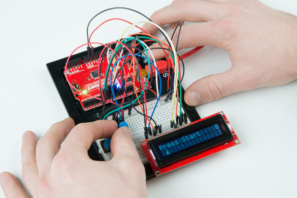
When the code finishes uploading, you should be presented with a flashing “Press Start” notification. If you do not see anything on the LCD, try turning the potentiometer to adjust the contrast.

Adjust the contrast with the potentiometer knob

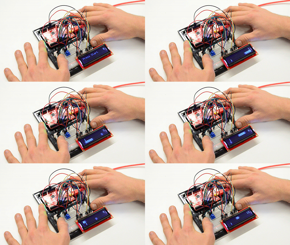
Press the button (the only button available) to begin the game. Once the game starts, you need to press the button again to jump in order to avoid the obstacles that zoom by. If you hit an obstacle, you must start over. The farther you run, the higher your score (as shown by the number in the upper right corner).

Playing the endless runner game

Resources and Going Further

For more on the Endless Runner Game project, the code and circuit diagram for this project can be found on GitHub.

Challenges

  1. Add a difficulty modifier to the game: for every 20 points earned, the terrain moves slightly faster.
  2. Add a second button and remove the “gravity” effect (the part that causes the hero to move back to the first row after jumping). One button causes the hero to move up, and the other causes the hero to move down. This creates more of an “endless flying” game rather than “endless running.” Feel free to change the hero graphic to a plane, spaceship, bird, mosquito, etc.
  3. Use an ultrasonic sensor to control the hero rather than one or more buttons. Set a threshold so that when an object (e.g. a hand) is more than 5 inches from the sensor, the hero is on the top row, and when the object is less than 5 inches from the sensor, the hero is on the bottom row.

Need some inspiration for your next project? Check out some of these related tutorials:

BadgerHack: Gaming Add-On Kit

Make a Breakout clone with the BadgerHack Gaming Add-On Kit.

PiRetrocade Assembly Guide

Build your very own retro gaming controller using the SparkFun PiRetrocade Kit.

Simon Says Assembly Guide

No matter what flavor of the Simon Says Through-hole Soldering Kit you've purchased, this tutorial is here to guide you through the entire build process.

learn.sparkfun.com |CC BY-SA 3.0 | SparkFun Electronics | Niwot, Colorado
Clap On Lamp

$
0
0

Clap On Lamp a learn.sparkfun.com tutorial

Available online at: http://sfe.io/t715

Introduction

Perhaps you remember an “As Seen on TV” product known as “The Clapper” in the 1980s and 1990s. The TV commercials could be seen on almost every channel. The premise was simple: a 120 VAC relay would control power to appliances and respond to two sharp noises, specifically from clapping. We’re going to make our own version of this, but instead of controlling any appliance, we will operate a lamp chain using a servo.

Required Materials

You can complete this project with parts from the SparkFun Inventor’s Kit v4.0 and a Sound Detector board. Specifically, you will need:

Tools Needed:

Suggested Reading

If you aren’t familiar with the following concepts, we recommend checking out these tutorials before continuing:

What is an Arduino?

What is this 'Arduino' thing anyway?

Installing Arduino IDE

A step-by-step guide to installing and testing the Arduino software on Windows, Mac, and Linux.

Hobby Servo Tutorial

Servos are motors that allow you to accurately control the rotation of the output shaft, opening up all kinds of possibilities for robotics and other projects.
New!

SparkFun Inventor's Kit Experiment Guide - v4.0

The SparkFun Inventor's Kit (SIK) Experiment Guide contains all the information needed to build all five projects, encompassing 16 circuits, in the latest version of the kit, V4.0.

Hardware Assembly

Lamp Assembly

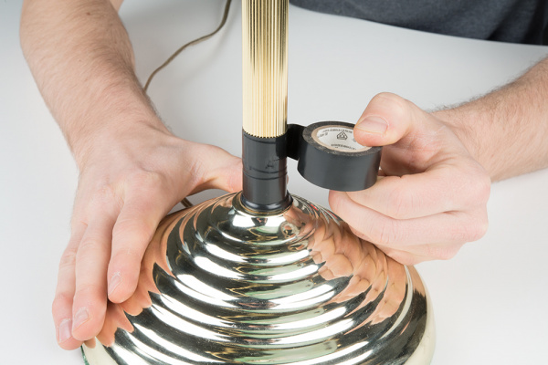
To start, we’ll attach the servo to the lamp first. If you want to protect your lamp’s finish, wrap some electrical tape around the post, covering about a 3-inch section.

Wrapping electrical tape around lamp

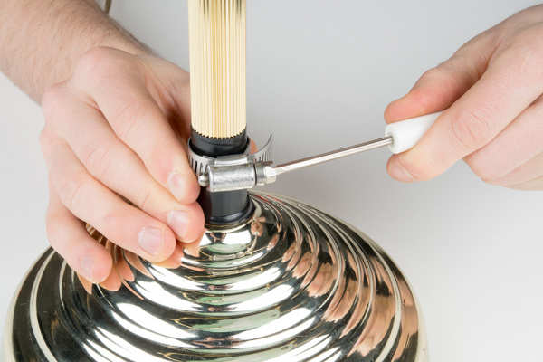
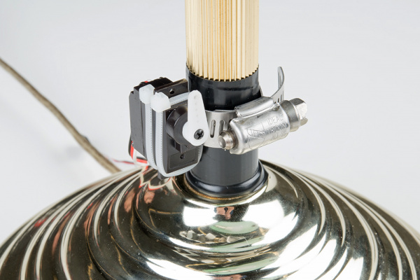
Use a screwdriver to tighten the hose clamp around the post about 1 inch above the base. Note that you may need to adjust the position of the servo later so that it can effectively pull the chain. Leave a small gap on one side.

Attaching hose clamp to lamp

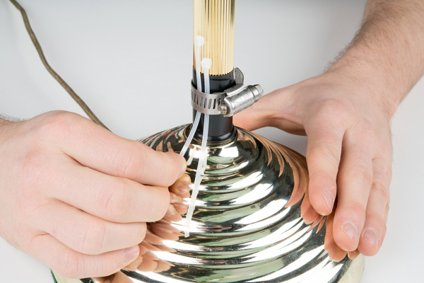
Thread two zip ties through the gap in the hose clamp

Pulling zip ties through hose clamp

Carefully pull the zip ties around the servo on either side of the flange. Pull the zip ties tight (you may need to use a set of needle nose pliers).

Pulling zip ties through hose clamp

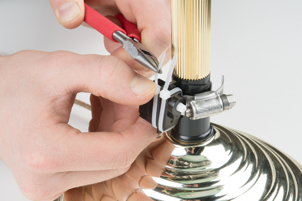
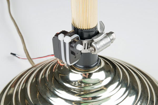
Tighten the hose clamp as needed and cut the ends of the zip ties.

Cut ends of zip ties

Using a screw, attach a servo arm to the servo’s shaft. Make sure that the arm can rotate from pointing directly up to directly down, rotating away from the lamp’s post. We’ll use that motion to pull the lamp’s chain.

Put servo arm on servo

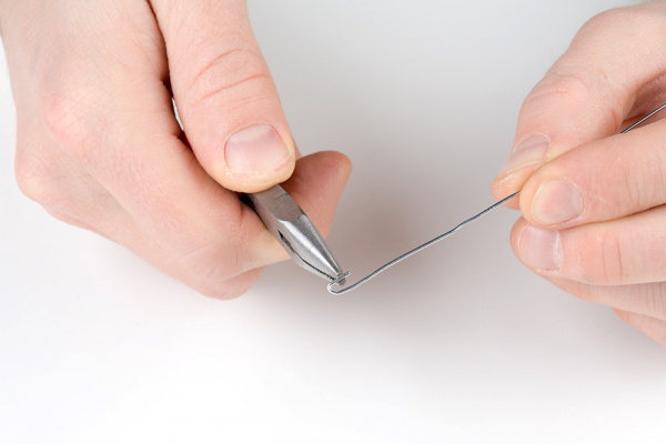
Straighten out a paper clip, and bend a hook in one end using needle nose pliers.

Bending paper clip

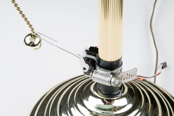
With the servo arm facing up, thread the hook through the outermost hole in the servo arm. Hold the other end of the paper clip up to the chain, and bend the paper clip so that it hooks onto the chain.

Attach other end of paper clip to chain

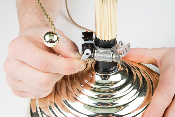
Try rotating the servo to make sure that the chain is pulled fully to switch the lamp. This may require readjusting a second paper clip hook so that the chain is pulled successfully on each rotation.

Make sure that the servo pulls the chain

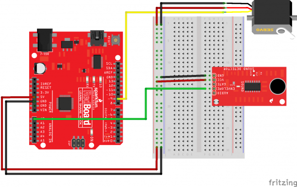
Circuit Diagram

Using jumper wires, connect the components as shown in the diagram below.

Clap on lamp Fritzing diagram

Having a hard time seeing the circuit? Click on the image for a closer look.

Programming

Note: This example assumes you are using the latest version of the Arduino IDE on your desktop. If this is your first time using Arduino, please review our tutorial on installing the Arduino IDE.

Copy and paste the following code in the Arduino IDE. Click Upload to send your compiled code to the Arduino.

language:c
/**
 * Clap On Light
 * Date: November 9, 2017
 * Author: Shawn Hymel (SparkFun Electronics)
 *
 * Connect a servo to a lamp chain/switch to turn it on and off
 * with two successive claps (or other loud noises).
 *
 * To complete this project, you will need parts from the
 * SparkFun Inventor's Kit v4.0:
 * https://www.sparkfun.com/products/14265 as well as a sound
 * detector board: https://www.sparkfun.com/products/14262 along
 * with a lamp, electrical tape, hose clamp, zip ties, and a
 * paper clip.
 *
 * This sketch was written by SparkFun Electronics, with lots of
 * help from the Arduino community. This code is completely free
 * for any use.
 */

#include <Servo.h>

// Pins
const int SERVO_PIN = 9;
const int SOUND_PIN = A0;

// Constants
const int THRESHOLD = 30;                           // Raw ADC
const unsigned long TIMEOUT = 500;                  // ms
const unsigned long TIME_BETWEEN_PULSES_MIN = 300;  // ms
const unsigned long TIME_BETWEEN_PULSES_MAX = 1000; // ms
const int PULSE_MIN = 40;                           // ms
const int PULSE_MAX = 300;                          // ms
const int SERVO_WAIT = 1000;                        // ms
const int SERVO_CCW = 0;                            // deg
const int SERVO_CW = 180;                           // deg

// Globals
unsigned long last_pulse_time = 0;
Servo servo;

void setup() {

  Serial.begin(9600);

  servo.attach(SERVO_PIN);
  servo.write(SERVO_CW);

  pinMode(SOUND_PIN, INPUT);
}

void loop() {

  // Look for pulse and take time it occured
  unsigned long pulse_length = readPulse(SOUND_PIN, THRESHOLD, TIMEOUT);
  if ( (pulse_length >= PULSE_MIN) &&
       (pulse_length <= PULSE_MAX) ) {
    unsigned long pulse_time = millis();
    Serial.println(pulse_time - last_pulse_time);

    // Check time between this pulse and the last one we saw
    if ( (pulse_time - last_pulse_time >= TIME_BETWEEN_PULSES_MIN) &&
         (pulse_time - last_pulse_time <= TIME_BETWEEN_PULSES_MAX) ) {
      Serial.println("Clap on!");
      pullChain();
    }

    last_pulse_time = pulse_time;
  }
}

// If the analog value is above the threshold, wait for it to
// drop below the threshold and return the time it was above
// the threshold. Return 0 if it's not above the threshold, and
// return the timeout value if it stays above the threshold for
// too long.
unsigned long readPulse(int pin, int threshold, unsigned long timeout) {

  unsigned long t = 0;

  // If above the threshold, wait for value to drop below it
  if ( analogRead(pin) >= threshold ) {
    unsigned long timestamp = millis();
    while ( (analogRead(pin) >= threshold) &&
            (millis() < timestamp + timeout) );
    t = millis() - timestamp;
  }

  return t;
}

// Pull the lamp chain by moving the servo far counterclockwise,
// wait 500 ms, and then move it far clockwise.
void pullChain() {
  servo.write(SERVO_CCW);
  delay(SERVO_WAIT);
  servo.write(SERVO_CW);
  delay(SERVO_WAIT);
}

What You Should See

Clap twice near the sound detector with a pause of about ½ second between claps. The servo should activate and pull the chain to switch the light on. Clap twice again, and the lamp should turn off.

Clap twice to switch the lamp!

Resources and Going Further

For more on the Clap On Lamp project, the example code and circuit diagram for this project can be found on GitHub.

Challenges

  1. Right now, the program looks for any two sharp, successive noises. This could mean tapping the table near the sensor, sneezing, or even just talking. See if you can modify the code to be more restrictive about what’s considered a “clap.” Can you have the servo activate only on clap sounds?
  2. Replace the sound detector sensor with another sensor, like a photocell. Have the lamp activate whenever another type of threshold is reached, such as getting too dark in a room.
  3. Write a computer program that looks for the local sunrise and sunset data on the internet and sends a command to the Arduino (e.g. over Serial) to turn the light on at sunset and off at sunrise.

Need some inspiration for your next project? Check out some of these related tutorials:

Mario the Magician's Magical Lapel Flower

A guest tutorial from the astonishingly talented Mario the Magician showing how to put together your own servo-controlled lapel flower.

Spectacle Example: Super Mario Bros. Diorama

A study in building an animated diorama (with sound!) using Spectacle electronics.

learn.sparkfun.com |CC BY-SA 3.0 | SparkFun Electronics | Niwot, Colorado
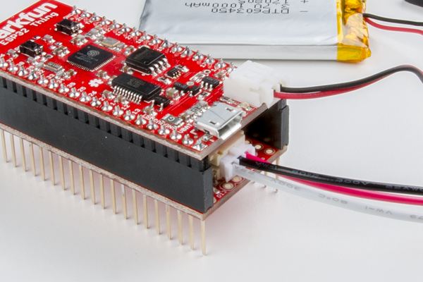
Light Seeking Robot

$
0
0

Light Seeking Robot a learn.sparkfun.com tutorial

Available online at: http://sfe.io/t713

Introduction

Euglena is a genus of single-celled organisms that live in bodies of fresh and salt water. Most species of Euglena have chloroplasts that are used for photosynthesis, much like plants. Additionally, most contain a single photoreceptor and eyespot, which allows the euglena to track and move toward light sources. To learn more about Euglena, see this Wikipedia page. You can also see hundreds of euglenas swimming around in this video.

To emulate euglena behavior, we’re going to make a light-seeking robot that moves toward areas of bright light. The SIK v4.0 only comes with 1 photocell (light sensor), which means that we will need to have our robotic “organism” turn left and right in order to detect the direction of brightest light.

Required Materials

You can complete this project with parts form the SparkFun Inventor’s Kit v4.0. Specifically, you will need:

You will also need:

  • Binder clip
  • Velcro or Dual Lock tape

Tools

Suggested Reading

If you aren’t familiar with the following concepts, we recommend checking out these tutorials before continuing:

What is an Arduino?

What is this 'Arduino' thing anyway?

Installing Arduino IDE

A step-by-step guide to installing and testing the Arduino software on Windows, Mac, and Linux.

TB6612FNG Hookup Guide

Basic hookup guide for the TB6612FNG H-bridge motor driver.
New!

SparkFun Inventor's Kit Experiment Guide - v4.0

The SparkFun Inventor's Kit (SIK) Experiment Guide contains all the information needed to build all five projects, encompassing 16 circuits, in the latest version of the kit, V4.0.

Hardware Assembly

To begin, make sure that your breadboard and Arduino are secured to the base plate. Complete instructions for attaching both can be found here.

Attaching Arduino to base plate

Using scissors, cut three strips of Dual Lock that are 1.25 inches (3.2 cm) long and 1 inch (2.5 cm) wide. Remove the adhesive backing, and attach two pieces to the corners under the base plate and a third in the center.

Attaching dual lock to robot base plate

Cut two more strips that are 1.25 inches (3.175cm) long and ¾ inch (1.9cm) wide. Remove the adhesive backing, and attach the strips to the two motors. Be sure that your motors are mirror images of each other when you attach the Dual Lock.

Attach dual lock to motors

Press the motors to the baseplate, connecting the two Dual Lock surfaces. Try to get the motors as straight as possible so your robot will drive straight.

Attach motors to robot base

The bottom of your baseplate should look like the image below. Remember that the two motors should be mirror images of each other.

Check your work

Note: The direction in which the motor wires face is arbitrary. Having them face out makes the circuit easier to build. Having them face in makes the circuit more robust against wires getting ripped out.

Attach the wheels by sliding them onto the plastic shafts on the gearmotor. The shaft is flat on one side, as is the wheel coupler. Align the two, and then press to fit the wheel onto the shaft.

Put wheels on motors

Clip the binder clip onto the back end of the robot. This will act as a caster as the robot drives around.

Use a binder clip as a caster

Cut a piece of Dual Lock that is about 1.25 inch x 1 inch (3.2cm x 2.5cm). Remove the adhesive backing and attach it to the back of the battery holder.

Attach dual lock to the battery pack

Press the battery holder to the baseplate so that the two pieces of Dual Lock snap together. Insert the batteries into the holder if you have not done so already. Remember that batteries are polarized and can only go in one way.

Attach battery pack to robot base plate

Circuit Diagram

Using jumper wires, connect the components as shown in the diagram below.

Fritzing diagram of robot wiring

Having a hard time seeing the circuit? Click on the image for a closer look.

Programming

Note: This example assumes you are using the latest version of the Arduino IDE on your desktop. If this is your first time using Arduino, please review our tutorial on installing the Arduino IDE.

Heads up! Make sure your switch is in the OFF position. As soon as the code is finished uploading, your robot will begin driving. Make sure it cannot drive off a table or other high surface and injure itself.

Copy and paste the following code in the Arduino IDE. Click Upload, and see what happens!

language:c
/**
 * Light Seeking Robot
 * Date: November 9, 2017
 * Author: Shawn Hymel (SparkFun Electronics)
 *
 * 2-wheeled robot moves toward the brightest light by first
 * checking left, right, and center.
 *
 * Parts for this project can be found in the SparkFun
 * Inventor's Kit v4.0: https://www.sparkfun.com/products/14265
 *
 * This sketch was written by SparkFun Electronics, with lots of
 * help from the Arduino community. This code is completely free
 * for any use.
 */

// Pins
const int PWMB = 8;
const int BIN2 = 9;
const int BIN1 = 10;
const int AIN1 = 11;
const int AIN2 = 12;
const int PWMA = 13;
const int SW_PIN = 7;     // Switch to turn the motors on and off
const int LIGHT_PIN = A0; // Photocell

// Constants
const int SEARCH_DRIVE_TIME = 200;  // Time to run one motor while searching
const int TURN_DRIVE_TIME = 200;    // Time to turn in a direction
const int MOVE_DRIVE_TIME = 300;   // Time to drive in a direction
const int STOP_DRIVE_TIME = 200;    // Time to stop after moving
const int NUM_LIGHT_LEVELS = 3;

void setup() {

  // Set switch pin
  pinMode(SW_PIN, INPUT_PULLUP);

  // Set the motor control pins as outputs
  pinMode(AIN1, OUTPUT);
  pinMode(AIN2, OUTPUT);
  pinMode(PWMA, OUTPUT);
  pinMode(BIN1, OUTPUT);
  pinMode(BIN2, OUTPUT);
  pinMode(PWMB, OUTPUT);

  // Initialize Serial comms
  Serial.begin(9600);
  Serial.println("Feed me photons!");
}

void loop() {

  // Store light levels as array [left, center, right]
  int light_levels[NUM_LIGHT_LEVELS];

  // If switch is flipped, search for light
  if(digitalRead(SW_PIN) == LOW){

    // Record light value to the left
    drive(0, 255);
    delay(SEARCH_DRIVE_TIME);
    drive(0, 0);
    delay(STOP_DRIVE_TIME);
    light_levels[0] = analogRead(LIGHT_PIN);
    drive(0, -255);
    delay(SEARCH_DRIVE_TIME);
    drive(0, 0);
    delay(STOP_DRIVE_TIME);

    // Record light value to the right
    drive(255, 0);
    delay(SEARCH_DRIVE_TIME);
    drive(0, 0);
    delay(STOP_DRIVE_TIME);
    light_levels[2] = analogRead(LIGHT_PIN);
    drive(-255, 0);
    delay(SEARCH_DRIVE_TIME);
    drive(0, 0);
    delay(STOP_DRIVE_TIME);

    // Record light value in the center
    light_levels[1] = analogRead(LIGHT_PIN);

    // Find direction of max light
    int max_light = 0;
    int max_light_index = 0;
    for ( int i = 0; i < NUM_LIGHT_LEVELS; i++ ) {
      if ( light_levels[i] > max_light ) {
        max_light = light_levels[i];
        max_light_index = i;
      }
      Serial.print(light_levels[i]);
      Serial.print("");
    }
    Serial.println();
    Serial.print("Max light: ");
    Serial.println(max_light_index);

    // Move in the direction of max light
    if ( max_light_index == 0 ) {
      Serial.println("Chasing light to the left");
      drive(-100, 255);
      delay(TURN_DRIVE_TIME);
      drive(255, 255);
      delay(MOVE_DRIVE_TIME);
      drive(0, 0);
      delay(STOP_DRIVE_TIME);
    } else if ( max_light_index == 1 ) {
      Serial.println("Chasing light straight ahead");
      drive(255, 255);
      delay(MOVE_DRIVE_TIME);
      drive(0, 0);
      delay(STOP_DRIVE_TIME);
    } else {
      Serial.println("Chasing light to the right");
      drive(255, -100);
      delay(TURN_DRIVE_TIME);
      drive(255, 255);
      delay(MOVE_DRIVE_TIME);
      drive(0, 0);
      delay(STOP_DRIVE_TIME);
    }

  // If switch is not flipped, do nothing
  } else {
    drive(0, 0);
  }
}

void rightMotor(int motorSpeed)
{

  // If speed is positive, run the motor forward
  if (motorSpeed > 0) {
    digitalWrite(AIN1, HIGH);
    digitalWrite(AIN2, LOW);

  // If it's negative, run the motor backward
  } else if (motorSpeed < 0) {
    digitalWrite(AIN1, LOW);
    digitalWrite(AIN2, HIGH);

  // If it's 0, brake the motor
  } else {
    digitalWrite(AIN1, LOW);
    digitalWrite(AIN2, LOW);
  }
  analogWrite(PWMA, abs(motorSpeed));
}

void leftMotor(int motorSpeed)
{
  // If speed is positive, run the motor forward
  if (motorSpeed > 0) {
    digitalWrite(BIN1, HIGH);
    digitalWrite(BIN2, LOW);

  // If it's negative, run the motor backward
  } else if (motorSpeed < 0) {
    digitalWrite(BIN1, LOW);
    digitalWrite(BIN2, HIGH);

  // If it's 0, brake the motor
  } else {
    digitalWrite(BIN1, LOW);
    digitalWrite(BIN2, LOW);
  }
  analogWrite(PWMB, abs(motorSpeed));
}

void drive(int leftSpeed, int rightSpeed) {
  leftMotor(leftSpeed);
  rightMotor(rightSpeed);
}

What You Should See

When the switch is OFF, the robot will not move. When you turn the switch ON, the robot will turn left and right, taking light measurements at each extreme. It will also take a light measurement from the center.

Robot looking for light

The robot turns to the direction with the most light and moves forward a small amount. It then repeats the pattern of looking for light and moving toward the direction of brightest light.

Robot moving toward light

Note that trying to direct the robot with a flashlight or other light source can be difficult sometimes. Reflected light from the wheels can sometimes be brighter, for instance, than reflected light on the ground. It can take some patience to get the robot to move the way you want. You can also try modifying the code to make it faster at searching or taking more than 3 measurements at a time.

Resources and Going Further

For more on the Light Seeking Robot project, the code and circuit diagram for this project can be found on GitHub.

Next Steps

Right now, your robot has only one sensor and performs a very simple search-decide-move loop. If you wanted to make your mechanical and electrical “organism” more robust and smarter, you can add additional sensors, such as an Ultrasonic Distance Sensor to determine if the robot is about to hit an object.

Additionally, you can give your robot very simple artificial intelligence (AI) by using algorithms like Q-Learning so that it learns how to respond to various sensor inputs.

Need some inspiration for your next project? Check out some of these related tutorials:

Experiment Guide for RedBot with Shadow Chassis

This Experiment Guide offers nine experiments to get you started with the SparkFun RedBot. This guide is designed for those familiar with our SparkFun Inventors Kit and want to take their robotics knowledge to the next level.

SparkFun Line Follower Array Hookup Guide

Learn how to connect the RedBot Line Following Sensor Bar to an arduino type microcontroller. Use the example sketches to read data from the bar, and try out a simple line following algorithm.

learn.sparkfun.com |CC BY-SA 3.0 | SparkFun Electronics | Niwot, Colorado
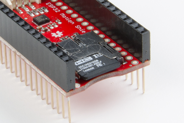
Vibe-O-Matic 3000

$
0
0

Vibe-O-Matic 3000 a learn.sparkfun.com tutorial

Available online at: http://sfe.io/t717

Introduction

It all starts because a friend sent me a link to a baby crib that Ford made.

I had no idea how much money or time Ford spent but I figured I could do something similar. It might be a little too DIY… And my son might not like it at all… But I present to you:

The Vibe-O-Matic 3000

Baby in bouncy chair with Arduino

VOM3K

Ok, what’s going on here? The VOM3K is designed to replicate every aspect of riding in a car. The seat vibrates to varying degrees much the way a car will turn on, drive for a bit, stop at lights, etc. The seat lights up on the sides in a pulsating way just like a car’s headlights will light up the cabin. And the speakers play a recording of road noise recorded during a 15 minute drive.

Now for the big question. Does the baby like it, or LOVE it? Turns out the baby is just damned confused by it. The smart little bugger knows it’s not the car but he doesn’t quite know what it is. He doesn’t fuss or cry when he’s in it but doesn’t pass out like in the back seat of the car. Instead he tends to stare up at me with an inquisitive look I can only interpret as “Dad, why do you keep saying the word Arduino. Am I Arduinoing right now?!”

Here’s the part list:

The Build

To build the Vibe-O-Matic I needed three things:

  • Light
  • Sound
  • Vibration

Luckily the bouncy seat that friends gave us (thank you Victoria!) had a small vibration motor attached.

Baby bouncy chair

The original vibration design used a single C cell battery (approximately 1.5V) with a simple on/off slide switch. I removed the power switch and battery and used the MOSFET power control kit to control the motor via the Arduino at 5V.

Vibration motor modified with MOSFET control

Vibration motor modified with MOSFET control

What does the motor do when run at 5V instead of the designed 1.5V? It runs a lot faster and a lot louder. Thankfully the Arduino has PWM on a handful of pins so we are able to run the motor from 0 to 100% throttle meaning if the vibration is too great (or the motor gets too warm) we can ramp down the power to an acceptable level. I ended up running the motor from about 40% to 80% power. Any higher and the boy gets even more weirded out.

Arduino Pro with MP3 Shield

Arduino Pro with MP3 Shield

Next I soldered an Arduino Pro to the MP3 Player Shield. Note that the Arduino is mounted above the shield. It’s not mandatory that an Arduino go below a shield. I knew I was going to need to solder a variety of additional things like switches and buttons to the Arduino. It was easier for me to mount the MP3 shield below so I could see the pins I needed to access on the Arduino.

MDF base board

MDF base board

I made a base board out of MDF to mount everything to. I had some extra paint around so I painted it (thinking a coat of paint would have a positive impact on my wife’s feelings about this whole endeavor). The speakers are attached with a couple of screws through the MDF into the plastic speaker housing. The enclosure and electronics were similarly secured with a couple screws.

Bouncy chair mounted to baseboard

Bouncy chair mounted to baseboard

The chair was then zip tied to the MDF. The individually addressable APA102 warm white LEDs had an adhesive backing like most strips do. But like most LED strips, this backing tends to wear out after a few days so I added hot-glue to various points on the LED strip to secure it.

Cylon LEDs emulating passing headlights

Cylon LEDs emulating passing headlights

The APA102 LEDs are controlled with the excellent FastLED library. The ‘Cylon’ example was modified to mimic car’s headlights illuminating the cabin as they pass on the left, right, and front.

Next I recorded a 12 minute drive through my city with the windows down. If you listen to the track you can hear where a couple large diesel trucks pass by. It’s a pretty good track although it’s hard to pick up good road noises. At one point I envisioned using a light sensor, GPS, and accelerometer to properly record the light and vibration through the drive. At that same moment my son started to scream and I decided it was better to take the FISI (screw it, ship it) approach: the LEDs trigger every 30 seconds with a random right/front/left decision and the vibration motor changes to a new, random, vibration level (40 to 80% throttle) every 60 seconds.

The Code

Buttons to make the baby chair go

A stripped down UI

A rocker switch was used to select between Vibe (vibrate for 15 minutes, no lights or sound) and Car (the full effect). The Go! button allows the user to start or stop an action.

You can find the code for the Vibe-O-Matic 3000 here. It looks at the state of the rocker switch and the start button to determine what to do. Once actuated the MP3 shield plays the track until completion. The LEDs and motor turn on and off randomly every 30 and 60 seconds respectively. There’s also a vibe-only’ mode that vibrates the chair for 15 minutes.

The Result

In the end Jack doesn’t really like or dislike the seat. I suspect the snugness of car seat is important. I also think the vibrations in a car are at a lower frequency and a much higher amplitude than the small vibe motor can do. I hope someone can learn from my lessons and do an even better version!

Resources and Going Further

Now that you’ve seen how to hack a perfectly good baby gift it’s time to take on the world! Check out some of these other great tutorials:

Light-Emitting Diodes (LEDs)

Learn the basics about LEDs as well as some more advanced topics to help you calculate requirements for projects containing many LEDs.

MP3 Player Shield Hookup Guide V15

How to get your Arduino groovin' using the MP3 Player Shield.
New!

SparkFun Inventor's Kit Experiment Guide - v4.0

The SparkFun Inventor's Kit (SIK) Experiment Guide contains all the information needed to build all five projects, encompassing 16 circuits, in the latest version of the kit, V4.0.

Lumenati Hookup Guide

Lumenati is our line of APA102c-based addressable LED boards. We'll show you how to bring the sparkle to your projects!

Thanks for reading! Please let us know if you have any questions or comments.


learn.sparkfun.com |CC BY-SA 3.0 | SparkFun Electronics | Niwot, Colorado

Light-Seeking Robot

$
0
0

Light-Seeking Robot a learn.sparkfun.com tutorial

Available online at: http://sfe.io/t713

Introduction

Euglena is a genus of single-celled organisms that live in bodies of fresh and salt water. Most species of Euglena have chloroplasts that are used for photosynthesis, much like plants. Additionally, most contain a single photoreceptor and eyespot, allowing the Euglena to track and move toward light sources. To learn more about Euglena, see this Wikipedia page. You can also see hundreds of Euglenas swimming around in this video.

To emulate Euglena behavior, we’re going to make a light-seeking robot that moves toward areas of bright light. The SIK v4.0 only comes with one photocell (light sensor), which means that we will need to have our robotic “organism” turn left and right in order to detect the direction of brightest light.

Required Materials

You can complete this project with parts from the SparkFun Inventor’s Kit v4.0. Specifically, you will need:

You will also need (included in the SIK v4.0):

  • Binder clip
  • Velcro or Dual Lock fastener

Tools Needed:

Suggested Reading

If you aren’t familiar with the following concepts, we recommend checking out these tutorials before continuing:

What is an Arduino?

What is this 'Arduino' thing anyway?

Installing Arduino IDE

A step-by-step guide to installing and testing the Arduino software on Windows, Mac, and Linux.

TB6612FNG Hookup Guide

Basic hookup guide for the TB6612FNG H-bridge motor driver.
New!

SparkFun Inventor's Kit Experiment Guide - v4.0

The SparkFun Inventor's Kit (SIK) Experiment Guide contains all the information needed to build all five projects, encompassing 16 circuits, in the latest version of the kit, v4.0.

Hardware Assembly

To begin, make sure that your breadboard and Arduino are secured to the baseplate. Complete instructions for attaching both can be found here.

Attaching Arduino to base plate

Using scissors, cut three strips of Dual Lock that are 1.25 inches (3.2cm) long and 1 inch (2.5cm) wide. Remove the adhesive backing, and attach two pieces to the corners under the baseplate and a third in the center.

Attaching dual lock to robot base plate

Cut two more strips that are 1.25 inches (3.175cm) long and ¾ inch (1.9cm) wide. Remove the adhesive backing, and attach the strips to the two motors. Be sure that your motors are mirror images of each other when you attach the Dual Lock.

Attach dual lock to motors

Press the motors to the baseplate, connecting the two Dual Lock surfaces. Try to get the motors as straight as possible so your robot will drive straight.

Attach motors to robot base

The bottom of your baseplate should look like the image below. Remember that the two motors should be mirror images of each other.

Check your work

Note: The direction in which the motor wires face is arbitrary. Having them face out makes the circuit easier to build. Having them face in makes the circuit more robust against wires getting ripped out.

Attach the wheels by sliding them onto the plastic shafts on the gearmotor. The shaft is flat on one side, as is the wheel coupler. Align the two, and then press to fit the wheel onto the shaft.

Put wheels on motors

Clip the binder clip onto the back end of the robot. This will act as a caster as the robot drives around.

Use a binder clip as a caster

Cut a piece of Dual Lock that is about 1.25 inch x 1 inch (3.2cm x 2.5cm). Remove the adhesive backing and attach it to the back of the battery holder.

Attach dual lock to the battery pack

Press the battery holder to the baseplate so that the two pieces of Dual Lock snap together. Insert the batteries into the holder if you have not done so already. Remember that batteries are polarized and can only go in one way.

Attach battery pack to robot base plate

Circuit Diagram

Using jumper wires, connect the components as shown in the diagram below.

Fritzing diagram of robot wiring

Having a hard time seeing the circuit? Click on the image for a closer look.

Programming

Note: This example assumes you are using the latest version of the Arduino IDE on your desktop. If this is your first time using Arduino, please review our tutorial on installing the Arduino IDE.

Heads up! Make sure your switch is in the OFF position. As soon as the code is finished uploading, your robot will begin driving. Make sure it cannot drive off a table or other high surface and injure itself.

Copy and paste the following code in the Arduino IDE. Click Upload and see what happens!

language:c
/**
 * Light Seeking Robot
 * Date: November 9, 2017
 * Author: Shawn Hymel (SparkFun Electronics)
 *
 * 2-wheeled robot moves toward the brightest light by first
 * checking left, right, and center.
 *
 * Parts for this project can be found in the SparkFun
 * Inventor's Kit v4.0: https://www.sparkfun.com/products/14265
 *
 * This sketch was written by SparkFun Electronics, with lots of
 * help from the Arduino community. This code is completely free
 * for any use.
 */

// Pins
const int PWMB = 8;
const int BIN2 = 9;
const int BIN1 = 10;
const int AIN1 = 11;
const int AIN2 = 12;
const int PWMA = 13;
const int SW_PIN = 7;     // Switch to turn the motors on and off
const int LIGHT_PIN = A0; // Photocell

// Constants
const int SEARCH_DRIVE_TIME = 200;  // Time to run one motor while searching
const int TURN_DRIVE_TIME = 200;    // Time to turn in a direction
const int MOVE_DRIVE_TIME = 300;   // Time to drive in a direction
const int STOP_DRIVE_TIME = 200;    // Time to stop after moving
const int NUM_LIGHT_LEVELS = 3;

void setup() {

  // Set switch pin
  pinMode(SW_PIN, INPUT_PULLUP);

  // Set the motor control pins as outputs
  pinMode(AIN1, OUTPUT);
  pinMode(AIN2, OUTPUT);
  pinMode(PWMA, OUTPUT);
  pinMode(BIN1, OUTPUT);
  pinMode(BIN2, OUTPUT);
  pinMode(PWMB, OUTPUT);

  // Initialize Serial comms
  Serial.begin(9600);
  Serial.println("Feed me photons!");
}

void loop() {

  // Store light levels as array [left, center, right]
  int light_levels[NUM_LIGHT_LEVELS];

  // If switch is flipped, search for light
  if(digitalRead(SW_PIN) == LOW){

    // Record light value to the left
    drive(0, 255);
    delay(SEARCH_DRIVE_TIME);
    drive(0, 0);
    delay(STOP_DRIVE_TIME);
    light_levels[0] = analogRead(LIGHT_PIN);
    drive(0, -255);
    delay(SEARCH_DRIVE_TIME);
    drive(0, 0);
    delay(STOP_DRIVE_TIME);

    // Record light value to the right
    drive(255, 0);
    delay(SEARCH_DRIVE_TIME);
    drive(0, 0);
    delay(STOP_DRIVE_TIME);
    light_levels[2] = analogRead(LIGHT_PIN);
    drive(-255, 0);
    delay(SEARCH_DRIVE_TIME);
    drive(0, 0);
    delay(STOP_DRIVE_TIME);

    // Record light value in the center
    light_levels[1] = analogRead(LIGHT_PIN);

    // Find direction of max light
    int max_light = 0;
    int max_light_index = 0;
    for ( int i = 0; i < NUM_LIGHT_LEVELS; i++ ) {
      if ( light_levels[i] > max_light ) {
        max_light = light_levels[i];
        max_light_index = i;
      }
      Serial.print(light_levels[i]);
      Serial.print("");
    }
    Serial.println();
    Serial.print("Max light: ");
    Serial.println(max_light_index);

    // Move in the direction of max light
    if ( max_light_index == 0 ) {
      Serial.println("Chasing light to the left");
      drive(-100, 255);
      delay(TURN_DRIVE_TIME);
      drive(255, 255);
      delay(MOVE_DRIVE_TIME);
      drive(0, 0);
      delay(STOP_DRIVE_TIME);
    } else if ( max_light_index == 1 ) {
      Serial.println("Chasing light straight ahead");
      drive(255, 255);
      delay(MOVE_DRIVE_TIME);
      drive(0, 0);
      delay(STOP_DRIVE_TIME);
    } else {
      Serial.println("Chasing light to the right");
      drive(255, -100);
      delay(TURN_DRIVE_TIME);
      drive(255, 255);
      delay(MOVE_DRIVE_TIME);
      drive(0, 0);
      delay(STOP_DRIVE_TIME);
    }

  // If switch is not flipped, do nothing
  } else {
    drive(0, 0);
  }
}

void rightMotor(int motorSpeed)
{

  // If speed is positive, run the motor forward
  if (motorSpeed > 0) {
    digitalWrite(AIN1, HIGH);
    digitalWrite(AIN2, LOW);

  // If it's negative, run the motor backward
  } else if (motorSpeed < 0) {
    digitalWrite(AIN1, LOW);
    digitalWrite(AIN2, HIGH);

  // If it's 0, brake the motor
  } else {
    digitalWrite(AIN1, LOW);
    digitalWrite(AIN2, LOW);
  }
  analogWrite(PWMA, abs(motorSpeed));
}

void leftMotor(int motorSpeed)
{
  // If speed is positive, run the motor forward
  if (motorSpeed > 0) {
    digitalWrite(BIN1, HIGH);
    digitalWrite(BIN2, LOW);

  // If it's negative, run the motor backward
  } else if (motorSpeed < 0) {
    digitalWrite(BIN1, LOW);
    digitalWrite(BIN2, HIGH);

  // If it's 0, brake the motor
  } else {
    digitalWrite(BIN1, LOW);
    digitalWrite(BIN2, LOW);
  }
  analogWrite(PWMB, abs(motorSpeed));
}

void drive(int leftSpeed, int rightSpeed) {
  leftMotor(leftSpeed);
  rightMotor(rightSpeed);
}

What You Should See

When the switch is OFF, the robot will not move. When you turn the switch ON, the robot will turn left and right, taking light measurements at each extreme. It will also take a light measurement from the center.

Robot looking for light

The robot turns to the direction with the most light and moves forward a small amount. It then repeats the pattern of looking for light and moves toward the direction of brightest light.

Robot moving toward light

Note that trying to direct the robot with a flashlight or other light source can be difficult. Reflected light from the wheels can sometimes be brighter, for instance, than reflected light on the ground. It can take some patience to get the robot to move the way you want. You can also try modifying the code to make it faster at searching or taking more than three measurements at a time.

Resources and Going Further

The code and circuit diagram for the Light-Seeking Robot project can be found on GitHub.

Next Steps

Right now, your robot has only one sensor and performs a very simple search-decide-move loop. If you wanted to make your mechanical and electrical “organism” more robust and smarter, you could use additional sensors, such as an Ultrasonic Distance Sensor to determine if the robot is about to hit an object.

Additionally, you could give your robot very simple artificial intelligence (AI) by using algorithms like Q-Learning so that it learns how to respond to various sensor inputs.

Need some inspiration for your next project? Check out some of these related tutorials:

Experiment Guide for RedBot with Shadow Chassis

This Experiment Guide offers nine experiments to get you started with the SparkFun RedBot. This guide is designed for those who are familiar with our SparkFun Inventor's Kit and want to take their robotics knowledge to the next level.

SparkFun Line Follower Array Hookup Guide

Learn how to connect the RedBot Line-Following Sensor Bar to an Arduino-type microcontroller. Use the example sketches to read data from the bar, and try out a simple line-following algorithm.

learn.sparkfun.com |CC BY-SA 3.0 | SparkFun Electronics | Niwot, Colorado

Qwiic HAT for Raspberry Pi Hookup Guide

$
0
0

Qwiic HAT for Raspberry Pi Hookup Guide a learn.sparkfun.com tutorial

Available online at: http://sfe.io/t704

Introduction

This Qwiic HAT for Raspberry Pi is the quickest and easiest way to utilize SparkFun’s Qwiic ecosystem while still using that Raspberry Pi that you’ve come to know and love. This Qwiic HAT connects the I2C bus (GND, 3.3V, SDA, and SCL) on your Raspberry Pi to an array of Qwiic connectors. It also has a few important pins on the Raspberry Pi broken out for easy access. Since the Qwiic system allows for daisy chaining (as long as your devices are on different addresses), you can stack as many sensors as you’d like to create a tower of sensing power!

SparkFun Qwiic HAT for Raspberry Pi

DEV-14459
$4.95

Required Materials

To follow along with this hookup guide, you will need any Raspberry Pi with 2x20 male headers.

Raspberry Pi 3

DEV-13825
$39.95
80

A Pi Zero W will also work but you will need to make sure to solder some male headers to it.

Raspberry Pi GPIO Male Header - 2x20

PRT-14275
$0.95
Raspberry Pi Zero W

DEV-14277
$10.00
11

Now you probably didn’t buy the Qwiic HAT if you didn’t have any Qwiic products to use with it, right? If you don’t have any Qwiic products, the following might not be a bad place to start.

SparkFun Environmental Combo Breakout - CCS811/BME280 (Qwiic)

SEN-14348
$34.95
1
SparkFun Spectral Sensor Breakout - AS7262 Visible (Qwiic)

SEN-14347
$24.95
SparkFun GPS Breakout - XA1110 (Qwiic)

GPS-14414
$44.95
SparkFun Qwiic Adapter

DEV-14495
$0.95

Finally, you’ll need our handy Qwiic cables to easily connect sensors to your Qwiic HAT. Below are a few options.

Qwiic Cable - 500mm

PRT-14429
$1.95
Qwiic Cable - 100mm

PRT-14427
$1.50
Qwiic Cable - 200mm

PRT-14428
$1.50
Qwiic Cable - 50mm

PRT-14426
$0.95

Required Setup Tools

As a desktop, these devices are required:

Suggested Reading

If you aren’t familiar with our new Qwiic system, we recommend reading here for an overview. We would also recommend taking a look at the following tutorials if you aren’t familiar with them.

I2C

An introduction to I2C, one of the main embedded communications protocols in use today.

Hardware Overview

The Qwiic HAT has 4 Qwiic connect ports, all on the same I2C bus. In addition to this, some of the pins on the Raspberry Pi are broken out for the user.

Top View of Qwiic Hat

Hardware Assembly

To get started with your Qwiic HAT, simply plug it into the headers on the Raspberry Pi, make sure that the “USB” arrow on the HAT is pointing towards the USB on the Raspberry Pi.

alt text

Once the HAT is plugged in, you can start plugging in any Qwiic enabled sensors you might have.

alt text

I2C on Raspberry Pi

OS and Library Install

If you’re starting from scratch, with a blank microSD card, you’ll want to install Raspbian. If you’ve already got a working Raspbian system, skip ahead to step 3.

  1. Download the NOOBS image. As of this writing, it’s at version 2.4.4.
  2. Follow the official installation instructions.
  3. Follow the Wiring Pi Instructions to get git, update and upgrade your Rasbpian packages, then install WiringPi.

Be patient – each of these steps takes a while.

Once you’ve got wiringPi installed, run the gpio commands shown below.

>gpio -v>gpio readall

It should respond with some information about the wiringPi version and the Pi that its running on, then draw a table illustrating the configuration for the pins in the 40-pin connector.

Configuration

Like the SPI peripheral, I2C is not turned on by default. Again, we can use raspi-config to enable it.

  1. Run sudo raspi-config.
  2. Use the down arrow to select 5 Interfacing Options
  3. Arrow down to P5 I2C.
  4. Select yes when it asks you to enable I2C
  5. Select OK and then Finish

Once you return to terminal, enter this command

>ls /dev/*i2c*

The Pi should respond with

/dev/i2c-1

Which represents the user-mode I2C interface.

Utilities

There is a set of command-line utility programs that can help get an I2C interface working. You can get them with the apt package manager.

sudo apt-get install -y i2c-tools

In particular, the i2cdetect program will probe all the addresses on a bus, and report whether any devices are present. Call i2cdetect -y 1 to probe the first I2C bus, which is what the Qwiic HAT is connected to.

pi@raspberrypi:~/$ i2cdetect -y 1
     0  1  2  3  4  5  6  7  8  9  a  b  c  d  e  f
00:          -- -- -- -- -- -- -- -- -- -- -- -- --
10: -- -- -- -- -- -- -- -- -- -- -- -- -- -- -- --
20: -- -- -- -- -- -- -- -- -- -- -- -- -- -- -- --
30: -- -- -- -- -- -- -- -- -- -- -- -- -- -- -- --
40: -- -- -- -- -- -- -- -- -- -- -- -- -- -- -- --
50: -- -- -- -- -- -- -- -- -- -- -- -- -- -- -- --
60: 60 -- -- -- -- -- -- -- -- -- -- -- -- -- -- --
70: -- -- -- -- -- -- -- --

This map indicates that there is a peripheral at address 0x60. We can read and write its registers using the i2cget, i2cset and i2cdump commands.

Resources and Going Further

For more information, check out the resources below:

Now that you have your Qwiic HAT ready to go, it’s time to check out some of SparkX’s Qwiic enabled products, many of which are on their way to becoming good old fashioned SparkFun products.

Qwiic Micro OLED

SPX-14269
$14.95
Qwiic Magnetometer - MLX90393

SPX-14294
$14.95
Qwiic Mux - PCA9548A

SPX-14293
Qwiic Water-Resistant OLED

SPX-14287
$24.95

But I Already Have Sensors!

If you already have a handful of SparkFun sensors and parts? SparkFun has been putting our standard GND/VCC/SDA/SCL pinout on all our I2C boards for many years. This makes it possible to attach a Qwiic Adapter that will get your SparkFun I2C sensor or actuator onto the Qwiic system.

Here is the list of the boards that have the standard I2C pinout and will work with the Qwiic adapter board:

Check out this related tutorial:

Raspberry Pi SPI and I2C Tutorial

October 29, 2015

How to use the serial buses on your Raspberry Pi.

learn.sparkfun.com |CC BY-SA 3.0 | SparkFun Electronics | Niwot, Colorado


Qwiic Adapter Hookup Guide

$
0
0

Qwiic Adapter Hookup Guide a learn.sparkfun.com tutorial

Available online at: http://sfe.io/t689

Introduction

The SparkFun Qwiic adapter board is the perfect board to use if you need to make any old I2C board into a Qwiic enabled board. This adapter breaks out the I2C pins from the Qwiic connectors to pins that you can easily solder with your favorite I2C enabled device.

SparkFun Qwiic Adapter

DEV-14495
$0.95

Suggested Materials

To follow along with this tutorial, you will need a I2C enabled device and some headers:

Break Away Headers - Straight

PRT-00116
$1.50
20
Female Headers

PRT-00115
$1.50
7
Break Away Male Headers - Right Angle

PRT-00553
$1.95
4

You will also need our handy Qwiic connectors to easily connect the adapter to your development board or system. Below are a few options:

Qwiic Cable - Breadboard Jumper (4-pin)

PRT-14425
$1.50
Qwiic Cable - 500mm

PRT-14429
$1.95
Qwiic Cable - 100mm

PRT-14427
$1.50
Qwiic Cable - 50mm

PRT-14426
$0.95

Tools

You will need a soldering iron, solder, and general soldering accessories. To modify the headers, you will also need needle nose pliers and diagonal cutters.

Hakko FX888D Soldering Station

TOL-11704
$99.95
48
Solder Lead Free - 100-gram Spool

TOL-09325
$7.95
6
Needle Nose Pliers

TOL-08793
$1.95
1
Diagonal Cutters

TOL-08794
$1.95
2

Suggested Reading

If you aren’t familiar with our new Qwiic system, we recommend reading here for an overview. We would also recommend taking a look at the following tutorials if you aren’t familiar with them.

How to Solder: Through-Hole Soldering

This tutorial covers everything you need to know about through-hole soldering.

Logic Levels

Learn the difference between 3.3V and 5V devices and logic levels.

I2C

An introduction to I2C, one of the main embedded communications protocols in use today.

Hardware Overview

There are a few things you should know about the Qwiic system before you go plugging in I2C devices willy nilly. The first thing to be aware of is that all Qwiic devices run on 3.3V. So if you have a 5V device and you are not using a stackable breakout board with a logic level converter (such as the Qwiic Shield for Arduino), you’ll need to grab a logic level converter to boost your signals up to 5V. Also, be aware that all Qwiic devices have pull-up resistors on the I2C lines. So if your device does not have it, you’ll need to add those in or use the ones on your microcontroller.

The Qwiic adapter is populated with two 4-pin 1mm JST connectors to quickly connect your I2C devices together. Four plated through holes are broken out for SCL, SDA, 3.3V, and GND. These pins can be used to convert an old I2C enabled device into a Qwiic enabled board.

Top view of Qwiic Adapter

Hardware Assembly

There are several different ways to connect your I2C device to the Qwiic adapter. The simplest and probably cleanest method would be to use headers. This also allows the adapter to be reattached to a different I2C device in the future. I’ve found that I enjoy the look of the 90 degree male headers on the Qwiic Adapter, combined with a 90-degree bend in the legs on the female headers I2C device. However, you can really use any combination you’d like depending on how you want the adapter to be oriented relative to your I2C enabled board.

Using pliers, snap off a row of 4 pins from the right angle male header. Using diagonal cutters, you will need to sacrifice one socket in order cut off a row of 4 pins from the female header. Carefully bend the female header’s pins using the pliers to make a right angle with the I2C device. Solder the male headers to the Qwiic adapter and the female headers to the I2C device as shown in the image below.

Qwiic Adapter attached with 90-degree Headers

Once you’ve got headers soldered onto each of your boards, simply plug your adapter into your I2C enabled device. Using a Qwiic cable, plug your Qwiic adapter into a stackable Qwiic board of your choice. Assuming that there is example code loaded on your development board, you can now start reading data from your I2C enabled device!

Resources and Going Further

For more information, check out the resources below:

Now that you have your Qwiic adapter ready to go, it’s time to check out some of SparkX’s Qwiic enabled products, many of which are on their way to becoming good old fashioned SparkFun products.

Qwiic Micro OLED

SPX-14269
$14.95
Qwiic Magnetometer - MLX90393

SPX-14294
$14.95
Qwiic Mux - PCA9548A

SPX-14293
Qwiic Water-Resistant OLED

SPX-14287
$24.95

More I2C Please

Here is the list of the boards that have the standard I2C pinout and will work with the Qwiic adapter board:


learn.sparkfun.com |CC BY-SA 3.0 | SparkFun Electronics | Niwot, Colorado
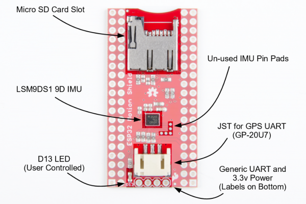
LilyPad ProtoSnap Plus Activity Guide

$
0
0

LilyPad ProtoSnap Plus Activity Guide a learn.sparkfun.com tutorial

Available online at: http://sfe.io/t710

Introduction

This guide will get you started with some introductory programming activities exploring each of the LilyPad pieces on the LilyPad ProtoSnap Plus. If you’ve never used Arduino to program before, this guide will walk you through the basics with example code to upload and explore.

You can follow along with this guide with both the LilyPad ProtoSnap Plus standalone board or the LilyPad ProtoSnap Plus Kit. This guide will not cover construction of a project with conductive thread, so either product will work for you.

LilyPad ProtoSnap Plus

DEV-14346
$39.95
LilyPad ProtoSnap Plus Kit

DEV-12922
$49.95

Required Materials

If using the LilyPad ProtoSnap Plus standalone board, you will need to supply your own micro-B USB cable to upload code. The LilyPad ProtoSnap Plus Kit includes one in the box.

USB micro-B Cable - 6 Foot

CAB-10215
$4.95
9
USB Micro-B Cable - 6"

CAB-13244
$1.95
3

Suggested Reading

What is an Arduino?

What is this 'Arduino' thing anyway?

Getting Started with LilyPad

An introduction to the LilyPad ecosystem - a set of sewable electronic pieces designed to help you build soft, sewable, interactive e-textile projects.

Before You Begin

To follow along with this guide, please install Arduino support for the LilyPad USB Plus by following the instructions in the LilyPad ProtoSnap Plus Hookup Guide.

LilyPad ProtoSnap Plus Hookup Guide

October 5, 2017

The LilyPad ProtoSnap Plus is a sewable electronics prototyping board that you can use to learn circuits and programming with Arduino, then break apart to make an interactive fabric or wearable project.

Before you begin working through the programming activities, confirm that:

You are running Arduino version 1.8 or higher
You have added SparkFun Boards to Arduino’s Preferences
SparkFun AVR Boards have been installed through the Boards Manager (ProtoSnap Plus examples are available in 1.1.8 or higher, you may need to update to see them)
"LilyPad USB Plus" appears in Arduino's "Board" menu
"LilyPad USB Plus" appears in Arduino's "Port" menu (when connected through a USB cable).

All of these installations are covered in detail in Setting Up Arduino section of the LilyPad ProtoSnap Plus Hookup Guide.

Once you’ve installed the LilyPad USB Plus extensions to Arduino, you’re ready to start programming the board!

Note that you won’t have to install the extensions again, but you will need to perform the below three steps every time you want to program the board. These three steps are:

1. Connect the LilyPad ProtoSnap Plus to your computer using a USB cable
2. Select "LilyPad USB Plus" from Arduino's "Board" menu
3. Select "LilyPad USB Plus" from Arduino's "Port" menu

Let’s go over the three steps in detail:

1. Connect the LilyPad ProtoSnap Plus to Your Computer

Place the LilyPad ProtoSnap Plus on a clean, non-metal work surface. Connect the LilyPad ProtoSnap Plus to a USB port on your computer using a micro-B USB cable. The cable can only be inserted one way, and should snap in securely.

USB Cable

Tip: Both the micro-B USB cable and the connector on the LilyPad have a subtle "D" shape to them. Match this shape to plug it in properly.

Connecto to Computer's USB Port

Slide the switch on the LilyPad USB Plus to the ON position. You will not be able to upload code to the board if it is set to the OFF position.

Turn LilyPad ProtoSnap Plus ON

2. Select LilyPad USB Plus from the Board Menu

If the Arduino board support was installed correctly, “LilyPad USB Plus” option will be available in the Tools>Board list under the SparkFun AVR Boards group. Open the menu and select LilyPad USB Plus. Depending on how many boards are already in the list, you may need to scroll down a bit to get to it. A dot (Windows) or check mark (Mac) will show next to the board in the menu when it is selected, and it will show next to Board in the Tools menu.

IMPORTANT: You'll see some LilyPad entries higher in the Arduino menu, but the LilyPad USB Plus is not one of them. You'll need to scroll down to the SparkFun section at the bottom of the list to find it. We're working on getting the LilyPad USB Plus added to the LilyPad group in the future.

Select Board Definition

Troubleshooting: If you don't see "LilyPad USB Plus" in the board list, go back to Setting Up Arduino and double check that you performed all the steps. You might try restarting Arduino as well.

3. Select LilyPad USB Plus from the Port Menu

Arduino needs to know which port your LilyPad USB Plus is attached to so it can program it. Whenever you plug a USB device into your computer, your computer will assign it a port number. This used to be difficult to determine, but this board has a handy feature that identifies itself. Go to the Tools>Port menu, and select the port that has “LilyPad USB Plus” next to it.

On Windows ports are listed as COM##; on a Mac or Linux machine they will be “/dev/cu.usbmodem####”. Your screen may look different than the image below, depending on what operating system you are using, but all should show LilyPad USB Plus next to the port address.

COM Port

Troubleshooting: If you don't see a port with "LilyPad USB Plus" next to it, ensure that the board is powered up (switch in the ON position), and that the USB cable is securely connected to both the board and your computer. Some micro-USB cables are only meant for charging and don't pass data - they'll power the board, but it won't show up in the port menu. If needed, try a different cable.

Hardware Overview

The LilyPad ProtoSnap Plus features twelve LilyPad components connected to a LilyPad microcontroller by conductive pathways called traces. For reference, each component on the ProtoSnap has a nearby label with its name and the number of the LilyPad USB Plus sew tab it is connected to. For more information on features and technical specs, please refer to the LilyPad ProtoSnap Plus Hookup Guide.

LilyPad Protosnap Plus parts Highlighted

LilyPad USB Plus

The LilyPad USB Plus is an Arduino-compatible microcontroller similar to the LilyPad Arduino USB - ATmega32U4 Board but with some additional features and three additional sew tabs. It is currently only available on the LilyPad ProtoSnap Plus.

Additional SMD LEDs

Features:

  • USB port for connecting to a computer.
  • Two sets of power (+) and ground (-) sew tabs.
  • Built-in RGB LED attached to pins 12 (R), 13 (G), and 14 (B).
  • A row of six white LEDs attached to pins 15-20.
  • Charging circuit for single-cell (3.7V) Lithium-Polymer batteries.

What is a Program?

Programs are sets of instructions that tell a computer to do something, (also called “code” or a “sketch” in Arduino) . This could be blinking LEDs, playing sounds, making decisions based on input from sensors, or a combination of all those things.

When the computer runs a program, it will start at the first instruction, carry it out, and move on to the next one. These instructions come from a specific list of words that the computer knows. If you type in a word that the computer doesn’t know (or more likely, you misspell a word that the computer should know), you’ll get an error when you try to run your program. Don’t feel bad, this happens to everyone and is a normal part of writing programs, and we’ll provide you with some troubleshooting tips as you follow along with the activities in this guide.

In the Arduino system, you’ll write programs on your computer in a free application called the Arduino IDE (“IDE” stands for Integrated Development Environment). This is a specialized text editor with extra buttons to check and send your code to the LilyPad USB Plus at the center of your ProtoSnap board. There are lots of programming examples built into the Arduino IDE, we’ll be using some of them in these activities.

What is a Microcontroller?

The LilyPad USB Plus at the center of your ProtoSnap board contains a tiny computer called a microcontroller. It can’t do all the things that a larger computer does, but it’s very good at running programs that control simple hardware like LEDs.

Unlike larger computers, microcontrollers don’t have keyboards and screens for input and output. Most of your input and output will happen through sew tabs; the silver petals with holes in them evenly spaced around the outer edge of all LilyPad boards. Your program can control the sew tabs. It can use them for output by turning them on and off (internally connecting them to voltage or not). It can also use them for input, measuring any voltage coming from other components. It can use this information to read buttons, switches, and various sensors, and use that information to make decisions. (We’ll explore this in future activities.)

If you look closely at the sew tabs, you’ll see that every sew tab has a label next to it. These are the names of the sew tabs, which you’ll need to know to control them from your program. You might have noticed that some of the sew tabs have an “A” as part of the label, and some include a tilde or squiggle “~”. These symbols describe special features that some of the sew tabs have. We’ll tell you about these special features in future activities.

Some of the sew tabs have a “+” or “-” next to them. You can use these sew tabs to provide power and ground to LilyPad boards connected to the LilyPad USB Plus.

Sew Tabs and Pins

Every microcontroller chip has electrical connections to the board that look like metal legs. These are commonly referred to as pins. Each sew tab around the outside edge of the LilyPad USB Plus is connected electrically to one of these pins on the microcontroller chip. These connections are not as easy to see as the external connections (traces) between the USB Plus and the boards included on the rest of the ProtoSnap Plus. In this guide, we'll be referring to sew tabs when referencing the hardware and electrical connections on your ProtoSnap and pins when talking about the code that controls electricity in or out of the tabs.

Read more about the LilyPad USB Plus’s individual sew tabs and connections (including a chart) in the LilyPad ProtoSnap Plus Hookup Guide.

1: Blinking LEDs

In this activity, you’ll run your first program on the LilyPad USB Plus at the center of the LilyPad ProtoSnap Plus. It will “just” make an LED blink, but there’s a lot going on even in this simple task. Let’s get started!

LilyPad Boards Used in This Activity

  • LilyPad USB Plus
  • Yellow LilyPad LEDs

Parts used

What is an LED?

“LED” stands for “Light Emitting Diode”. These are electronic components that light up when electricity passes through them. They come in a variety of colors; your ProtoSnap board includes yellow, red, green, and blue ones, and the LilyPad USB Plus has a built-in bargraph of white LEDs and a special "red-green-blue" (RGB) LED that can display a rainbow of colors.

New Concepts Introduced in This Activity

Exploring Your First Program

We’ve provided a pre-written example program that we’ll load into the Arduino IDE.

Basic Program Structure

We’ll walk you through the example program, explain how it’s constructed, and go over the two basic functions every program needs; setup() and loop().

Lighting Up LEDs

We’ll show you how to light up and blink LEDs using the pinMode(), digitalWrite(), and delay() commands.

Modifying Code

A great way to learn to program is to make small changes to a program that someone else has written, and see what happens. We’ll suggest places to try this, and give you a few challenges at the end of each activity.

Example Code

For each of these activities, we’ll start with a pre-written program that you’ll explore and modify. To load the first program, start up the Arduino IDE and go to:

File > Examples > LilyPadProtoSnapPlus > LPP_01_Blink

Select Example

Your menu of options may look different depending on what boards you have installed in Arduino.
You may have to scroll down to see the LilyPad ProtoSnap Plus examples option.

If you don't see the examples as shown, check that you have SparkFun AVR Boards version 1.1.8 or above installed in the Boards Manager. See Setting Up Arduino section of the LilyPad ProtoSnap Plus Hookup Guide for more information.

You can also copy and paste the following code into the Arduino IDE (be sure to delete any code already in the window first).

language:c
/*
LilyPad ProtoSnap Plus Activity 1: Blinking LEDs
SparkFun Electronics
https://www.sparkfun.com/products/14346

Blink the pair of yellow LEDs attached to sew tab A5 on the LilyPad USB Plus

Follow the tutorial at:
https://learn.sparkfun.com/tutorials/lilypad-protosnap-plus-activity-guide#1-blinking-leds

This example is based on: Blink by Scott Fitzgerald
https://www.arduino.cc/en/Tutorial/Blink

This code is released under the MIT License (http://opensource.org/licenses/MIT)

******************************************************************************/

// The setup function runs once when the microcontroller starts up or resets:

void setup()
{
  // Before you use a sew tab (pin), you must set it to be either an input or output:

  pinMode(A5, OUTPUT);    // Set pin A5 to be an output
}

// After the setup function runs, the loop function runs over and over forever:

void loop()
{
  digitalWrite(A5, HIGH); // Give pin A5 a HIGH voltage level (on), which lights up the LED
  delay(1000);            // Pause for 1000 milliseconds (one second), the LED stays on
  digitalWrite(A5, LOW);  // Give pin A5 a LOW voltage level (off), which turns off the LED
  delay(1000);            // Pause for 1000 milliseconds (one second), the LED stays off
}

Once you’ve connected your LilyPad ProtoSnap Plus to your computer as shown in the Before You Begin section, and loaded or copied the example program into the Arduino IDE, click the upload button (the round button with the right arrow at the top of the window) and see what happens!

Upload Button

What You Should See

Once the code has uploaded, the pair of yellow LEDs on the ProtoSnap Plus will blink once per second.

Why do two LEDs light up when I am only setting one pin to blink?

In the LilyPad ProtoSnap Plus, the LEDs are connected to the sew tabs in pairs; This is known as a parallel circuit. If you turn on one of the sew tabs, you'll turn on both LEDs as they share the same power source. This allows you to have the option of more LEDs attached to your project without needing additional sew tabs.

Understanding Your Program

In this section, we’ll explain what this program does. For this first activity we’ll be pretty thorough. As we progress through future activities, we’ll just highlight new concepts as we introduce them.

Program Overview

  1. Turn the LED on by sending power to Pin A5.
  2. Wait 1 second.
  3. Turn the LED off by cutting power to Pin A5.
  4. Wait 1 second.
  5. Repeat.

Comments

At the top of the program, you’ll find text describing what the program does, who wrote it, etc. These are called comments. They are there solely for your information and are ignored by the microcontroller. Comments in the Arduino IDE will show up asgray text.

Example Comments

We use special symbols to tell the microcontroller to ignore comments.

  • If you want to write a block of text on multiple lines as we’ve done above, the microcontroller will ignore any text between /* and */.

  • If you want to put a comment on a single line, the microcontroller will ignore any text after two slashes //.

Adding comments to your program is a very good habit to get into! It will help you immensely when you return to your program later and want to understand what you were trying to do. They are also a great tool to add notes for someone who may be using or sharing your code.

Setup() Function

The next section of our program contains a function. A function is a named block of code that does a defined task or set of tasks. When a function is run, all of the code contained between the curly brackets { and } is run. Arduino has two essential functions that are required for every program to run properly: they are setup() and loop(). Arduino programs can use many functions (both built-in and user defined), but they must at least have those two. These and other control structure functions built into the Arduino software will display in green text. Let’s explore the setup function.

Setup

When the microcontroller starts up or is reset, the setup() function runs once. As you may have guessed from the name, the setup() function is typically used to “set up” the hardware so that it operates properly during the rest of the program.

Statements and Commands

Inside functions, we put statements. A statement is a single instruction to the microcontroller. Statements always end with semicolons ;. It’s a common error to forget the semicolon, so if you get an error when uploading your code, double-check that every statement ends with ;.

Most statements will include commands. Commands are specific functions you can use to complete common tasks in Arduino. There are many built-in commands that can be used for all sorts of things - input and output, math, decision making, etc. These commands display in orange text. We’ll cover many useful commands in this guide.

In this program, we’ve put one command in the startup function, called pinMode(). Note the unusual capitalization, called “camel case”. Commands are case-sensitive, so pay special attention to this.

The pinMode() command, as you may have guessed, sets the mode of a pin. Pins are the metal legs on microcontroller chips that are attached to the sew tabs on your LilyPad board. Pins can be configured as inputs or outputs. In this program, we’re going to use pin A5 to control an LED, which is a component sending information (light) to the world, so we’ll make it an OUTPUT.

Commands take various numbers of parameters, which are the information the command needs from you. Parameters go inside parentheses () after a command, and are separated by commas if there are multiple. The pinMode command takes two parameters; the number of the pin, and whether you want it to be an INPUT or an OUTPUT. Here, we’re setting pin A5 to be an OUTPUT.

Reserved Words in Arduino IDE

You may have noticed some parameters are shown inblue text and others plain black. Colored text indicates one of Arduino's reserved words. A reserved word can be a variable, function, or command that has a specified use in the Arduino software. If you are typing something in your code and it displays in colored text, it has a pre-set meaning for Arduino. We'll learn more about variable naming in the next activity. For a full list of reserved words, visit the Arduino Reference website.

Loop() Function

The second essential function needed to run an Arduino program is called loop(). After the setup() function runs once, the loop() function runs over and over, forever (or until you turn off or reset the microcontroller).

A loop() function usually contains the main tasks and behaviors of your program; the things you want it to do repeatedly. You can use this to your advantage; for example, in this program we want to blink an LED continuously. Because the loop() function repeats, we only need to write the code to blink it once, and the loop() function will make it blink over and over.

loop

The first thing we’ll do is turn our LED on. To do that, we’ll use the digitalWrite() command.

Like pinMode(), digitalWrite() takes two parameters: the pin we want to control, and whether we want to make the pin a HIGH voltage level (on), or a LOW voltage level (off). We want to turn the LED on, so we’ll set pin A5 to HIGH.

Because the microcontroller runs so fast, if we immediately turned the LED off, you’d never notice it. So we’ll slow things down with a command called delay() that does nothing but pause the program for a set amount of time.

The delay() function takes one parameter, the number of milliseconds to wait. There are 1000 milliseconds in one second, so here we’re pausing for one second. If you make this value smaller, the LED will blink faster, and vice-versa. Try it!

After we’ve waited one second, we’ll turn the LED off with a second digitalWrite(), this time setting the pin to LOW to turn the LED off.

Finally, we’ll add a second delay(). This one pauses while the LED is off, finishing the complete on-off “blink” cycle. If we didn’t have the second delay(), the LED would immediately turn on again when loop() starts over. This happens so quickly you wouldn’t notice it being off.

Coding Challenges

  • Try changing the number inside delay() - Can you make the LED blink faster or slower?

  • Changing the pin number inside the digitalWrite() function will change the sew tab being controlled by the code. Can you light up one of the other LilyPad LEDs on the ProtoSnap by changing this number? Hint: don’t forget to set that LED to be an OUTPUT first.

  • Can you modify the code to blink multiple LEDs?

2: Basic Color Mixing

Now that you know how to turn LEDs on and off, let’s try controlling a colorful LED. The LilyPad USB Plus at the center of the LilyPad ProtoSnap Plus has a built-in RGB (Red Green Blue) LED that can be controlled in your code just like the LED pairs from the last activity. Unlike the LEDs used in the Blink example, this LED is special - it is actually 3 small LEDs in one package - a red, green, and blue. You can access them in code to a variety of color combinations.

LilyPad Boards Used in This Activity

  • LilyPad USB Plus
  • LilyPad USB Plus’s built-in RGB LED
  • Red LilyPad LEDs
  • Green LilyPad LEDs
  • Blue LilyPad LEDs

LilyPad ProtoSnap Plus RGB LED and Red, Green, Blue LEDs highlighted

What is an RGB LED?

Inside an RGB LED are three smaller LEDs - a red, green, and blue. Each of these LEDs is connected to a pin on the LilyPad USB Plus microcontroller, and they are all connected through a common cathode (negative) pin. Unlike the LEDs connected externally to the LilyPad USB Plus through its numbered sew tabs, you cannot see the connections as easily on the built-in RGB. Next to the LED are text labels identifying the pins connected to each colored LED within the RGB.

New Concepts Introduced in This Activity

Declaring and Using Variables

A variable is a placeholder for values in your code, typically a descriptive word. While we could continue to write the sew tab or pin number we are referencing in our programs, a variable can make it easier to read, update, and share information within your code. Every time you want to create and use a variable, you must declare it - tell the program what type of data it is storing.

Creating and Naming Variables

Variables can be whatever word or phrase you like, except for specific reserved words within the Arduino IDE that are used for commands, functions, or other specified use. You can learn more about variable types and use on the Arduino Reference site.
Examples:
  • myvariable, MYVARIABLE, myVariable: variables can use a combination of upper case and lower case. It is common to use camel case to make a variable easier to read.
  • my_variable: an underscore is also an option, but no other symbols.
  • myVariable1: you can use numbers within a variable name, but cannot begin with a number
Tips for Naming Your Variables:
  • Use a short, easy to read or type name (up to 63 characters are accepted)
  • Use a meaningful word or phrase for your variables, such as the name of a sensor you are connecting your LilyPad USB Plus (or name and number if using more than one of the same type) or type of value it will be used for storing (such as brightness, duration, or ).

Color Mixing

In order to create colors with the RGB LED, you’ll have to set each of the LEDs within it individually. The combination of light from the LEDs mixed together creates new colors. The example code will display color in the RGB LED as well as lighting up the individual colored LED pairs at the bottom of the ProtoSnap Plus to to make it easier for you to track what is happening within the RGB LED.

Example Code

To open the code, go to:

File > Examples > LilyPadProtoSnapPlus > LPP_02_BasicColorMixing

You can also copy and paste the following code into the Arduino IDE. Hit upload, and see what happens!

language:c
/*
LilyPad ProtoSnap Plus Activity 2: Basic Color Mixing
SparkFun Electronics
https://www.sparkfun.com/products/14346

Create primary and secondary colors on the built-in RGB (Red/Green/Blue) LED

Follow the tutorial at:
https://learn.sparkfun.com/tutorials/lilypad-protosnap-plus-activity-guide#2-basic-color-mixing

This code is released under the MIT License (http://opensource.org/licenses/MIT)

******************************************************************************/

// The LilyPad USB Plus has a built-in RGB (Red / Green / Blue) LED.
// In this activity we'll use digitalWrite to tun the three LEDs on and off
// in various combinations to create eight primary and secondary colors.

// Create integer variables for our LED pins:

// The built-in LED:

int RGB_red = 12;
int RGB_green = 13;
int RGB_blue = 14;

// The colored LEDs along the bottom edge of the board:

int redLED = 6;
int greenLED = A7;
int blueLED = A8;

void setup()
{
  // Make all of our LED pins outputs:

  pinMode(RGB_red, OUTPUT);
  pinMode(RGB_green, OUTPUT);
  pinMode(RGB_blue, OUTPUT);
  pinMode(redLED, OUTPUT);
  pinMode(greenLED, OUTPUT);
  pinMode(blueLED, OUTPUT);
}

void loop()
{

  // This code will step through the six primary and secondary colors, plus white and black.

  // For each of these colors, we'll turn the necessary RGB LEDs on or off.
  // We'll also turn on the same LEDs on the bottom edge, so you can see what's being mixed.

  // Black (all LEDs off)

  // RGB LEDs:

  digitalWrite(RGB_red, LOW);
  digitalWrite(RGB_green, LOW);
  digitalWrite(RGB_blue, LOW);

  // Bottom-edge LEDs

  digitalWrite(redLED, LOW);
  digitalWrite(greenLED, LOW);
  digitalWrite(blueLED, LOW);
  delay(1000);

  // Red (red LED on)

  digitalWrite(RGB_red, HIGH);
  digitalWrite(RGB_green, LOW);
  digitalWrite(RGB_blue, LOW);

  digitalWrite(redLED, HIGH);
  digitalWrite(greenLED, LOW);
  digitalWrite(blueLED, LOW);
  delay(1000);

  // Yellow (red and green LEDs on)

  digitalWrite(RGB_red, HIGH);
  digitalWrite(RGB_green, HIGH);
  digitalWrite(RGB_blue, LOW);

  digitalWrite(redLED, HIGH);
  digitalWrite(greenLED, HIGH);
  digitalWrite(blueLED, LOW);
  delay(1000);

  // Green (green LED on)

  digitalWrite(RGB_red, LOW);
  digitalWrite(RGB_green, HIGH);
  digitalWrite(RGB_blue, LOW);

  digitalWrite(redLED, LOW);
  digitalWrite(greenLED, HIGH);
  digitalWrite(blueLED, LOW);
  delay(1000);

  // Cyan (blue and green LEDs on)

  digitalWrite(RGB_red, LOW);
  digitalWrite(RGB_green, HIGH);
  digitalWrite(RGB_blue, HIGH);

  digitalWrite(redLED, LOW);
  digitalWrite(greenLED, HIGH);
  digitalWrite(blueLED, HIGH);
  delay(1000);

  // Blue (blue LED on)

  digitalWrite(RGB_red, LOW);
  digitalWrite(RGB_green, LOW);
  digitalWrite(RGB_blue, HIGH);

  digitalWrite(redLED, LOW);
  digitalWrite(greenLED, LOW);
  digitalWrite(blueLED, HIGH);
  delay(1000);

  // Magenta (red and blue LEDs on)

  digitalWrite(RGB_red, HIGH);
  digitalWrite(RGB_green, LOW);
  digitalWrite(RGB_blue, HIGH);

  digitalWrite(redLED, HIGH);
  digitalWrite(greenLED, LOW);
  digitalWrite(blueLED, HIGH);
  delay(1000);

  // White (all LEDs on)

  digitalWrite(RGB_red, HIGH);
  digitalWrite(RGB_green, HIGH);
  digitalWrite(RGB_blue, HIGH);

  digitalWrite(redLED, HIGH);
  digitalWrite(greenLED, HIGH);
  digitalWrite(blueLED, HIGH);
  delay(1000);
}

What You Should See

After uploading your code, the RGB LED will step through a color sequence beginning with all LEDs off (‘black’), red, yellow, green, cyan, blue, magenta, and white. Once the color sequence is complete, the program will loop back to the beginning and repeat the sequence. To better showcase these color combinations, the code also turns on the colored LED pairs at the bottom of the LilyPad ProtoSnap Plus to coordinate with the RGB channels.

Turning on different combinations of three LEDs inside the RGB LED will create new colors. Combining the primary colors of light (red, green, and blue) gives different results than combining pigments in paints or inks. Turning on all three colors will create white - this is called additive color. Take a look a the graphic below to see what colors combine to create primary and secondary colors with light.

Venn Diagram for Additive Colors

Understanding Your Program

Program Overview

  1. Turn all of the LEDs off by cutting power to the pins associated with their variables (LOW).
    Wait 1 second.
  2. Display red:
    R: ON, G: OFF, B: OFF
    Wait 1 second.
  3. Display yellow:
    R: ON, G: ON, B: OFF
    Wait 1 second.
  4. Display green:
    R: OFF, G: ON, B: OFF
    Wait 1 second.
  5. Display cyan:
    R: OFF, G: ON, B: ON
    Wait 1 second,
  6. Display blue:
    R: OFF, G: OFF, B: ON
    Wait 1 second.
  7. Display magenta:
    R: ON, G: OFF, B: ON
    Wait 1 second.
  8. Display white:
    R: ON, G: ON, B: ON
    Wait 1 second.
  9. Repeat.

Code to Note

The rest of the activities will highlight new programming techniques and concepts as you progress through the guide in a special Code to Note sections. These will showcase specific lines of code and explain them in further detail.
CodeDescription
int RGB_red = 12;
int RGB_green = 13;
int RGB_blue = 14;

int redLED = 6;
int greenLED = A7;
int blueLED = A8;
Integer Variables:
In this program, we set variables for each of the colored LEDs we are using. Each variable has a descriptive name, which will help us easily keep track of color as we set the individual LEDs in the RGB LED to create color combinations. Notice the int before all the variables used in this program - "int" is short for integer. In addition to deciding the type of data stored in the variable, we can also intialize or preset the information in the variable. In this program, the variables store the number of the sew tab each LED is connected to. We will cover more ways to use variables in later activities, including different variable types. Variables are case sensitive, so make sure you type them identically each time you use in your program.
pinMode(RGB_red, OUTPUT);
pinMode(RGB_green, OUTPUT);
pinMode(RGB_blue, OUTPUT);

pinMode(redLED, OUTPUT);
pinMode(greenLED, OUTPUT);
pinMode(blueLED, OUTPUT);
Input or Output?:
Each LED you want to control needs to be declared individually as an OUTPUT, even the built-in LEDs within the RGB LED. These use the same format from the Blinking LEDs example, but replacing the sew tab number with the variable names declared at the start of the program.
digitalWrite(RGB_red, HIGH);
digitalWrite(RGB_green, LOW);
digitalWrite(RGB_blue, LOW);

digitalWrite(redLED, HIGH);
digitalWrite(greenLED, LOW);
digitalWrite(blueLED, LOW);
Creating Colors:
Take a look at the code and notice the RGB LED variables are grouped together. In this code, instead of using digitalWrite() and delay() to create a blink, we are using these commands to step through new colors by turning different combinations of the red, green, and blue channels HIGH and LOW. Examine the code to see how setting these LEDs on or off matches the color chart above.

Coding Challenges

  • Can you create a new color sequence on the RGB LED using a new order of colors being displayed?

  • Try changing the delay to create a faster or slower color sequence.

  • Create a new variable called yellowLED and assign it to the yellow LEDs on the ProtoSnap Plus. Can you make the yellow LEDs light up each time the RGB LED creates yellow? Remember to set the pinMode() for this LED to OUTPUT in the setup().

  • Create a variable called delayTime at the top of your code near the other variable declarations. Then replace the 1000 in each delay() function with this variable. This way you can easily set the delay between color steps once at the beginning of your code instead of copying and pasting in each part of the sequence.

3: Custom Color Mixing

In this program, you will continue mixing colors with the RGB LED, but use a new function to change the brightness of each channel in relation to each other. Adjusting the brightness of the red, green, and blue LEDs within the RGB will allow you to create a new range of values and color combinations.

LilyPad Boards Used in This Activity

  • LilyPad USB Plus
  • LilyPad USB Plus’s built-in RGB LED
  • Red LilyPad LEDs
  • Green LilyPad LEDs
  • Blue LilyPad LEDs

Parts Used

New Concepts Introduced in This Activity

Analog Output (Pulse Width Modulation)

Up until this point, you have been controlling LEDs by setting them to one of two states: HIGH (ON) or LOW (OFF). This is great for blinking, but what about adjusting the brightness of your LEDs? This is where analog output comes in handy. Your LilyPad USB Plus can mimic a range of brightness on the LEDs by using pulse width modulation. The microcontroller on the LilyPad USB Plus can switch voltage to the sew tabs on and off so quickly that it appears to your eyes as if more or less voltage is being provided to an LED. For example, by changing the percent of time that a pin is on, from 0 percent (always off) to 100 percent (always on), you can create the appearance of a range of brightnesses. This percentage is called a duty cycle.

Note: You may have noticed that some of the labels on the LilyPad USB Plus's sew tabs have a special symbol in front of them (~). This indicates that these pins on the LilyPad USB Plus are capable of Pulse Width Modulation. However, do not include the "~" symbol in your code. It is only provided to make it easy for you to check which pins can produce PWM (analog) output and is not used in addressing the pins on the LilyPad USB Plus in your program. If you try to use analog output commands on a tab without these capabilities, you will see unexpected results these are illustrated in Activity 4: Fading LEDs.

Color Mixing Continued

In the last example, you created basic primary and secondary colors by turning the red, green, and blue channels on or off with different combinations. In this activity, you’ll create tertiary colors by combining the three color channels at 50% brightness levels. There are actually millions of color combinations available using RGB LEDs once you begin experimenting with adjusting the brightness/saturation of each. This example will cover a set of twelve tertiary colors.

Example Code

To open the code, go to:

File > Examples > LilyPadProtoSnapPlus > LPP_03_CustomColorMixing

You can also copy and paste the following code into the Arduino IDE. Hit upload, and see what happens!

language:c
/*
LilyPad ProtoSnap Plus Activity 3: Custom Color Mixing
SparkFun Electronics
https://www.sparkfun.com/products/14346

Expand your color options using analogWrite and the RGB (Red Green Blue) LED

Follow the tutorial at:
https://learn.sparkfun.com/tutorials/lilypad-protosnap-plus-activity-guide#3-custom-color-mixing

This code is released under the MIT License (http://opensource.org/licenses/MIT)

******************************************************************************/

// The LilyPad USB Plus has a built-in RGB (Red / Green / Blue) LED.
// In this activity we'll use analogWrite to control the brightness of the three LEDs.
// Here we'll create a rainbow of tertiary colors by adding a 50%-brightness option.

// Create integer variables for our LED pins:

// The built-in LED:

int RGB_red = 12;
int RGB_green = 13;
int RGB_blue = 14;

// The colored LEDs along the bottom edge of the board:

int redLED = 6;
int greenLED = A7;
int blueLED = A8;

void setup() {

// Make all of our LED pins outputs:

  pinMode(RGB_red, OUTPUT);
  pinMode(RGB_green, OUTPUT);
  pinMode(RGB_blue, OUTPUT);
  pinMode(redLED, OUTPUT);
  pinMode(greenLED, OUTPUT);
  pinMode(blueLED, OUTPUT);
}

void loop()
{
  // In this code we'll step through twelve rainbow colors (primary, secondary, tertiary).

  // Unlike digitalWrite, which can be only HIGH (on) or LOW (off),
  // analogWrite lets you smoothly change the brightness from 0 (off) to 255 (fully on).
  // When analogWrite is used with the RGB LED, you can create millions of colors!

  // In the analogWrite functions:
  // 0 is off
  // 128 is halfway on (used for the tertiary colors)
  // 255 is full brigthness.

  // Red

  analogWrite(RGB_red,255);
  analogWrite(RGB_green,0);
  analogWrite(RGB_blue,0);

  analogWrite(redLED,255);
  analogWrite(greenLED,0);
  analogWrite(blueLED,0);
  delay(1000);

  // Orange

  analogWrite(RGB_red,255);
  analogWrite(RGB_green,128);
  analogWrite(RGB_blue,0);

  analogWrite(redLED,255);
  analogWrite(greenLED,128);
  analogWrite(blueLED,0);
  delay(1000);

  // Yellow

  analogWrite(RGB_red,255);
  analogWrite(RGB_green,255);
  analogWrite(RGB_blue,0);

  analogWrite(redLED,255);
  analogWrite(greenLED,255);
  analogWrite(blueLED,0);
  delay(1000);

  // Chartruese

  analogWrite(RGB_red,128);
  analogWrite(RGB_green,255);
  analogWrite(RGB_blue,0);

  analogWrite(redLED,128);
  analogWrite(greenLED,255);
  analogWrite(blueLED,0);
  delay(1000);

  // Green

  analogWrite(RGB_red,0);
  analogWrite(RGB_green,255);
  analogWrite(RGB_blue,0);

  analogWrite(redLED,0);
  analogWrite(greenLED,255);
  analogWrite(blueLED,0);
  delay(1000);

  // Spring Green

  analogWrite(RGB_red,0);
  analogWrite(RGB_green,255);
  analogWrite(RGB_blue,128);

  analogWrite(redLED,0);
  analogWrite(greenLED,255);
  analogWrite(blueLED,128);
  delay(1000);

  // Cyan

  analogWrite(RGB_red,0);
  analogWrite(RGB_green,255);
  analogWrite(RGB_blue,255);

  analogWrite(redLED,0);
  analogWrite(greenLED,255);
  analogWrite(blueLED,255);
  delay(1000);

  // Azure

  analogWrite(RGB_red,0);
  analogWrite(RGB_green,128);
  analogWrite(RGB_blue,255);

  analogWrite(redLED,0);
  analogWrite(greenLED,128);
  analogWrite(blueLED,255);
  delay(1000);

  // Blue

  analogWrite(RGB_red,0);
  analogWrite(RGB_green,0);
  analogWrite(RGB_blue,255);

  analogWrite(redLED,0);
  analogWrite(greenLED,0);
  analogWrite(blueLED,255);
  delay(1000);

  // Violet

  analogWrite(RGB_red,128);
  analogWrite(RGB_green,0);
  analogWrite(RGB_blue,255);

  analogWrite(redLED,128);
  analogWrite(greenLED,0);
  analogWrite(blueLED,255);
  delay(1000);

  // Magenta

  analogWrite(RGB_red,255);
  analogWrite(RGB_green,0);
  analogWrite(RGB_blue,255);

  analogWrite(redLED,255);
  analogWrite(greenLED,0);
  analogWrite(blueLED,255);
  delay(1000);

  // Rose

  analogWrite(RGB_red,255);
  analogWrite(RGB_green,0);
  analogWrite(RGB_blue,128);

  analogWrite(redLED,255);
  analogWrite(greenLED,0);
  analogWrite(blueLED,128);
  delay(1000);

}

What You Should See

After uploading your code the RGB LED will step through a rainbow sequence of red, orange, yellow, chartruese, green, spring green, cyan, azure, blue, violet, magenta, and rose, repeatedly. To better showcase these color combinations, the code also turns on the colored LED pairs at the bottom of the LilyPad ProtoSnap Plus to coordinate with the RGB channels.

By adjusting the brightness of each LED in the RGB LED individually, we open up a much wider range of color options to display than the previous activity. In fact, there are many more combinations than we show in the example code. The image below shows a chart of the tertiary colors the example program creates by stepping down the LEDs to half brightness, creating a rainbow with more color transitions than the Basic Color Mixing example. By using analog output to adjust the brightness of each color channel individually, the RGB LED can display almost any color you can choose from a color picker - if you are familiar with RGB sliders in a graphics program, you’ll recognize the 0-255 values used in this code.

alt text

Understanding Your Program

Program Overview

  1. Display red:
    R: 100%, G: 0%, B: 0%
    Wait 1 second.
  2. Display orange:
    R: 100%, G: 50%, B: 0%
    Wait 1 second.
  3. Display yellow:
    R: 100%, G: 100%, B: 0%
    Wait 1 second.
  4. Display chartruese:
    R: 50%, G: 100%, B: 0%
    Wait 1 second.
  5. Display green:
    R: 0%, G: 100%, B: 0%
    Wait 1 second.
  6. Display spring green:
    R: 0%, G: 100%, B: 50%
    Wait 1 second.
  7. Display cyan:
    R: 0%, G: 100%, B: 100%
    Wait 1 second.
  8. Display azure:
    R: 0%, G: 50%, B: 100%
    Wait 1 second.
  9. Display blue:
    R: 0%, G: 0%, B: 100%
    Wait 1 second.
  10. Display violet:
    R: 50%, G: 0%, B: 100%
    Wait 1 second.
  11. Display magenta:
    R: 100%, G: 0%, B: 100%
    Wait 1 second.
  12. Display rose:
    R: 100%, G: 0%, B: 50%
    Wait 1 second.
  13. Repeat.

Code to Note

CodeDescription
analogWrite(RGB_red,255);
analogWrite(RGB_green,0);
analogWrite(RGB_blue,0);

analogWrite(redLED,255);
analogWrite(greenLED,0);
analogWrite(blueLED,0);
Analog Write:
Notice that like digitalWrite(), the analog function takes two pieces of information - the pin it is controlling and a state to set that pin to. The analogWrite() function outputs a voltage between 0 and 3.3V on a pin, with this range divided into 255 steps, where digital output only had HIGH or LOW. This example uses three values to mix the rainbow of tertiary colors: 0 (OFF), 128 (50% brightness), and 255 (100% brightness). You can use any value between 0 and 255 when you begin to experiment with mixing your own colors.

Coding Challenges

  • Try using a color picker to find the R, G, and B values for an interesting color and use that in your program.

  • Try creating your own rainbow light patterns using different values for the color mixes.

4: Fading LEDs

So far in these activities, we’ve controlled the brightness of LEDs manually. In this activity, you’ll start letting the computer do the hard work. By using iteration (counting over a range of numbers), you can fade LEDs smoothly from off to on, a very nice effect you can use in your own projects.

LilyPad Boards Used in This Activity

  • LilyPad USB Plus
  • Yellow LilyPad LEDs
  • Red LilyPad LEDs

Parts Used

New Concepts Introduced in This Activity

Iteration Using For-Loops

We’ve already seen that the loop() function repeats forever. But there are many occasions in programming where you’ll want the microcontroller to do something a certain number of times, or count up or down between two numbers. The for() loop is perfect for this.

In this example, we will use the for() loop to slowly increment the brightness of a LED from fully off to fully on, then do the same thing in reverse to turn it off. This creates a “fading” or “breathing” pattern that is great for art projects.

Example Code

To open the code, go to:

File > Examples > LilyPadProtoSnapPlus > LPP_04_Fading

You can also copy and paste the following code into the Arduino IDE. Hit upload, and see what happens!

language:c
/*
LilyPad ProtoSnap Plus Activity 4: Fading LEDs
SparkFun Electronics
https://www.sparkfun.com/products/14346

Use for-loops to smoothly vary the brightness of LEDs

Follow the tutorial at:
https://learn.sparkfun.com/tutorials/lilypad-protosnap-plus-activity-guide#4-fading-leds

This code is released under the MIT License (http://opensource.org/licenses/MIT)

******************************************************************************/

// In the previous activity we showed you how to manually change the brightness of a LED.
// In this activity we'll show you how to program the computer to do all the work.

// Create integer variables for the LED pins we'll be using:

int redLED = 6;
int yellowLED = 5;

void setup()
{
  // Set the LED pins to be outputs:

  pinMode(redLED, OUTPUT);
  pinMode(yellowLED, OUTPUT);
}

void loop()
{
  // The two "for loops" below will make a LED fade on and off in a "breathing" pattern.

  // Create a new integer variable called brightness:

  int brightness;

  // Now we'll have the program automatically change the value of brightness
  // using a command called "for".

  // for is like a tiny version of loop. The for command has several parts:
  // 1. something to do before starting (brightness = 0)
  // 2. a test to decide whether to keep going (brightness <= 255)
  // 3. a block of commands to run (everything within the {} below the for)
  // 4. a command to run before doing it again (brightness = brightness + 1)

  // Here's a for command which will start brightness at 0, check to see if it's less than
  // or equal to 255, run the commands after it, then add one to brightness and start over:

  for (brightness = 0; brightness <= 255; brightness = brightness + 1)
  {
    // Within the loop, we'll use brightnes variable to control the brigthness of the LEDs:

    analogWrite(redLED, brightness);
    analogWrite(yellowLED, brightness);

    // NOTE that not all pins work with analogWrite!
    // The ones with a "~" in front of them will change brightness,
    // the others will only turn on if brightness > 128.
    // Both types are used above, run the code and note the difference between them.

    // The delay command controls the speed - if you make the delay larger,
    // it will slow down the loop. Smaller, and it will run faster:

    delay(5);
  }

  // What if we want the LED to start at full brightness and fade to black?
  // We can easily set up the for loop to run in reverse:

  for (brightness = 255; brightness >= 0; brightness = brightness - 1)
  {
    analogWrite(redLED, brightness);
    analogWrite(yellowLED, brightness);
    delay(5);
  }
}

What You Should See

Once you upload the program, the yellow and red LEDs on the ProtoSnap will light up. The red leds on ~6 will fade smoothly on and off, while the yellow LEDs on A5 will blink.

If you look at the code, both pins should be fading. This illustrates the difference between the “~” sew tabs which can handle pulse-width modulation, and those that can’t.

Understanding Your Program

Program Overview

  1. Set up the pins we’ll be using
  2. Create a for() loop that makes a variable iterate from 0 to 255
  3. Use that variable to fade the LEDs from off to on
  4. Create a for() loop from makes a variable iterate from 255 to 0
  5. Use that variable to fade the LEDs from on to off
  6. Repeat

Code to Note

Iteration, or making variables change over time, is a very powerful tool in programming. Here we’re using it to smoothly change the brightness of an LED using the analogWrite() command, but you can use it anywhere you want to do something a certain number of times, or you want to change a variable from one value to another in even steps.

Unlike other commands, the for() loop is set up using three statements, which we’ll cover below. You’ll use the same pattern often in your own programming.

CodeDescription
for (brightness = 0;
      brightness <= 255;
      brightness = brightness + 1)

{
analogWrite(redLED, brightness);
analogWrite(yellowLED, brightness);
delay(5);
}
An Incrementing for() Loop:
Here we're using a for() loop to increment the brightness variable from 0 to 255, running the set of commands within the brackets each time we change it. Let's walk through this code in detail:
for (brightness = 0;
      brightness <= 255;
      brightness = brightness + 1
)
Statements:
The for() loop is set up a bit differently than other commands. It's controlled by three statements in parentheses after the command. Since these are statements and not parameters, they're separated by semicolons.
for (brightness = 0;
      brightness <= 255;
      brightness = brightness + 1)
1. Set Up the Variable:
1. The first statement runs before the counting starts, and is used to set up the variable you'll be counting with. Here we're setting the brightness variable to zero, the number we're starting at.
for (brightness = 0;
      brightness <= 255;
      brightness = brightness + 1)
2. Test Brightness Variable:
The second statement is a test that the for() loop uses to decide whether to keep counting. Here we're checking to see if brightness is less than or equal to 255. If the statement is true, the for loop will keep counting. If it's false, the loop will end.
for (brightness = 0;
      brightness <= 255;
      brightness = brightness + 1)

{
analogWrite(redLED, brightness);
analogWrite(yellowLED, brightness);
delay(5);
}
If True, Run Code
If the test in the second statement is true, the for() loop will run all of the commands included in the brackets after the for() command. This is where we're setting the brightness of the LED using the brightness variable. Remember to include a delay to slow things down a bit!


We've introduced a small bug into this program: we're using analogWrite for sew tabs A5 and 6, but only sew tab 6 has the "~" symbol indicating that it supports Pulse-Width Modulation (PWM). Notice how A5 is off when the brightness value is below 50%, and on when it's above 50%. If you see your code doing this, now you'll know why.

for (brightness = 0;
      brightness <= 255;
      brightness = brightness + 1)
3. Change Variable
After the commands in the brackets are run, the third statement will change the variable before starting the loop over again. Here we're incrementing the brightness variable by one, but note that you can increment it by any amount, or even a negative value if you wish.
for (brightness = 255;
      brightness >= 0;
      brightness = brightness - 1)

{
analogWrite(redLED, brightness);
analogWrite(yellowLED, brightness);
delay(5);
}
A Decrementing for() Loop:
Further down in the program, there's a second for() loop that decrements brightness from 255 to 0. Now that you know a little about for() loops, can you spot the differences that make this work?

Coding Challenges

  • Change the delay() values to make the “pulsing” pattern go faster or slower.

  • Try modifying the code to make other LEDs pulse.

  • Can you create a “heartbeat” pattern? (Two on-off pulses then a rest.)

5: Play a Tune

The microcontroller on the LilyPad USB Plus can turn its outputs on and off very quickly. If you carefully choose the frequency at which you’re turning an output on and off, and send that signal to the buzzer on the LilyPad ProtoSnap Plus, you can create tones and simple musical tunes.

LilyPad Boards Used in This Activity

  • LilyPad USB Plus
  • LilyPad Buzzer

Parts Used

What is a Buzzer?

Inside the LilyPad Buzzer's plastic housing is a coil of wire and a small magnet. When current flows through this coil, it becomes magnetized and pulls towards the magnet, which makes a tiny “click”. When done thousands of times per second, the clicks create tones. In this activity, you’ll pulse the buzzer at specific frequencies to create musical notes. The buzzer can also be used to make alert sounds, robot beeps and boops, etc.

New Concepts Introduced in This Activity

Making Tones

You’ll use the tone() and noTone() commands to drive the buzzer at specific frequencies.

A tone’s pitch is what we perceive when we think of a note as being very high (screams, forks scratching plates, etc.) versus very low (like earth-rumbling bass). The pitch of a tone is very closely related to the frequency played through a speaker. If we toggle a pin from HIGH-to-LOW then LOW-to-HIGH 440 times per second, for example, it produces a 440 Hz (hertz) frequency - a “middle A” pitch. Humans can hear frequencies ranging from 20 (low-pitch, bass) to 20,000 Hz (high-pitch, “ow, my ears”).

Example Code

To open the code, go to:

File > Examples > LilyPadProtoSnapPlus > LPP_05_Tune

You can also copy and paste the following code into the Arduino IDE. Hit upload, and see what happens!

language:c
/*
LilyPad ProtoSnap Plus Activity 5: Play a Tune
SparkFun Electronics
https://www.sparkfun.com/products/14346

Play musical notes through the buzzer on the LilyPad ProtoSnap Plus

Follow the tutorial at:
https://learn.sparkfun.com/tutorials/lilypad-protosnap-plus-activity-guide#5-play-a-tune

Uses frequencies from "melody" by Tom Igoe: https://www.arduino.cc/en/Tutorial/toneMelody

This code is released under the MIT License: (http://opensource.org/licenses/MIT)

******************************************************************************/

// Create an integer variable naming the pin we'll use for the buzzer.
// On the ProtoSnap Plus, it's on A3.

int buzzer = A3;

// Map musical notes to their frequencies by creating variables for them.
// You can find the frequencies for higher and lower notes at:
// https://www.arduino.cc/en/Tutorial/toneMelody

int NOTE_C5 = 523;
int NOTE_CS5 = 554;
int NOTE_D5 = 587;
int NOTE_DS5 = 622;
int NOTE_E5 = 659;
int NOTE_F5 = 698;
int NOTE_FS5 = 740;
int NOTE_G5 = 784;
int NOTE_GS5 = 831;
int NOTE_A5 = 880;
int NOTE_AS5 = 932;
int NOTE_B5 = 988;
int NOTE_C6 = 1047;

// We'll also create a variable for how long to play each note in milliseconds.
// If you make this smaller, the notes will play faster.

int tempo = 500;

void setup()
{
  // Set the buzzer pin to be an output:

  pinMode(buzzer, OUTPUT);
}

void loop()
{
  // This code will play a simple scale from C5 to C6.

  // The tone command takes two parameters: a pin number and a frequency.
  // The tone will play until we stop it with the noTone command.
  // Each of the below blocks plays one note; the note plays during the delay command.

  tone(buzzer,NOTE_C5);
  delay(tempo);

  tone(buzzer,NOTE_D5);
  delay(tempo);

  tone(buzzer,NOTE_E5);
  delay(tempo);

  tone(buzzer,NOTE_F5);
  delay(tempo);

  tone(buzzer,NOTE_G5);
  delay(tempo);

  tone(buzzer,NOTE_A5);
  delay(tempo);

  tone(buzzer,NOTE_B5);
  delay(tempo);

  tone(buzzer,NOTE_C6);
  delay(tempo);

  // A longer delay at the end pauses the sound before looping again.
  // Here we're delaying four times the "tempo" value:

  noTone(buzzer);
  delay(tempo * 4);

  // Try writing your own song using the noted defined at the top of the program!
  // You can change the note duration by multiplying or dividing the "tempo" value
}

What You Should See

Once the code uploads, the buzzer will begin playing a simple musical scale over one octave, pause, and repeat.

Turn the volume up on your computer to hear the buzzer play a tune in the video

Understanding Your Program

Program Overview

  1. Define variables for the audio frequencies we’ll be using, and the tempo (speed at which we’ll be playing).
  2. Configure the sew tab connected to the buzzer to be an output.
  3. Play a series of notes using the tone command.
  4. Pause and repeat.

Code to Note

CodeDescription
int NOTE_C5 = 523;
int NOTE_CS5 = 554;
int NOTE_D5 = 587;
int NOTE_DS5 = 622;
int NOTE_E5 = 659;
int NOTE_F5 = 698;
int NOTE_FS5 = 740;
int NOTE_G5 = 784;
int NOTE_GS5 = 831;
int NOTE_A5 = 880;
int NOTE_AS5 = 932;
int NOTE_B5 = 988;
int NOTE_C6 = 1047;
Frequency and Notes:
To play a specific note you need to know its audio frequency (how fast the output needs to turn on and off). At the top of this program we've included variables for one octave (C5 to C6). These frequencies come from the Tone Melody tutorial on Arduino's site. If you want to play higher or lower notes you can find many more frequencies there.
int tempo = 500;
Setting Tempo:
Another variable we've created is called tempo. We'll use this to control the duration of all the notes, allowing you to change the speed of the tune from one place.
tone(buzzer,NOTE_C5);
Making Tones:
To actually make noise, we use the tone() command. It takes two parameters; the pin which has the buzzer attached to it, and the audio frequency to output.
tone(buzzer,NOTE_B5);
delay(tempo);
Setting Duration:
Once you run the tone() command, the buzzer will keep making sound forever, even while the program continues on to other things. To control the duration of the tone, we'll use delay() along with our tempo variable to pause while the tone is playing.
tone(buzzer,NOTE_B5);
delay(tempo);

tone(buzzer,NOTE_C6);
delay(tempo);

noTone(buzzer);
Changing and Stopping Sounds:
To actually stop the tone, you can run another tone() command with a different note, or use the noTone() command to turn off the sound. The noTone() command only needs one parameter, the pin number it is controlling. We use both methods in this program.
delay(tempo * 4);
Pauses and Tempo:
To pause before the loop() function repeats the scale, we're using another delay() at the end of the program. But to make it pause a bit longer, we multiply our tempo variable by four. This makes it pause for four times as long as each note plays. Half of music is the duration of the notes; you can use multiplication and division to turn individual notes into half notes, quarter notes, create rests, etc. Soon you'll be making real music!

Coding Challenges

  • This program plays a simple scale. Can you change the program to play an actual song?

  • In this program we used a variable called tempo to change the durations of all the notes. In actual music, notes have different durations, and rests (periods of no sound) are important as well. Can you change the durations of individual notes by adding math to the delay values? Hint: If tempo is the duration of a whole note, tempo / 2 would be the duration of a half note, etc.

6: Buttons and Switches

In the activities thus far, you have been using outputs - components that receive a signal or power from the LilyPad USB Plus and send information (light and sound) to the world. In the next few activities, we will start to receive input from the world using buttons and sensors to affect the LilyPad boards on the ProtoSnap Plus.

LilyPad Boards Used in This Activity

  • LilyPad USB Plus
  • LilyPad Button
  • Yellow LilyPad LEDs
  • Blue LilyPad LEDs
  • LilyPad Slide Switch

Parts Used

What is a Switch?

A switch is type of component that controls current flow in a circuit. The LilyPad Slide Switch is an example of a maintained switch, meaning its state remains the same until changed. The board has a small switch labeled ON/OFF; when the toggle is moved to the ON position, the two sew tabs on the switch are connected, allowing current to flow through and close the circuit. When moved to OFF, parts inside the switch move away from each other and open the circuit (disconnecting it).


What is a Button?

The LilyPad Button Board is a special type of switch called a momentary switch - it is only active when an action is applied. When you press the button in the middle of the board, it connects the two sew tabs and allows current to flow through. When you let go of the button, the connection is opened again, and the button springs back into place.

Learn more about how buttons and switches work and the different types you can use in Switch Basics.

New Concepts Introduced in This Activity

Digital Input

Just as digital outputs have two states, ON or OFF (HIGH or LOW in code), digital inputs also have two states. We’ll use a special function called digitalRead() to check if the button has been pressed or if the switch has been flipped when attached to a sew tab on the LilyPad USB Plus.

Internal Pull-up Resistors

A pull-up resistor is a small circuit that holds the voltage HIGH (3.3V) on a pin until a button is pressed, pulling the voltage LOW (0V). The most common place you will see a pull-up resistor is when working with buttons. A pull-up resistor keeps the button in one state until it is pressed. The LilyPad USB Plus has built-in pull-up resistors, which we will use in code.

Variables for State Change

In Fading LEDs, the for() loop set a variable that was changed during the program. In this activity, you’ll read the state of a button or switch to a variable to hold its state for later use in your program.

If Statements

In the Fading LEDs example, we explored a specialized function, the for() loop. In this activity, we’ll use another function called an If Statement that will check if a state is true or false. Then we will make decisions based on the reading it receives. If/else functions are a way to start adding behavior based on input in your code, whereas the for() loop example created some automation. As you learn more specialized functions in Arduino (or write your own), your programs will become more complex and able to execute more complicated commands and interactions.

Example Code

To open the code, go to:

File > Examples > LilyPadProtoSnapPlus > LPP_06_Button

You can also copy and paste the following code into the Arduino IDE. Hit upload, and see what happens!

language:c
/*
LilyPad ProtoSnap Plus Activity 6: Buttons and Switches
SparkFun Electronics
https://www.sparkfun.com/products/14346

Explore digital input and program flow control using the button and switch

Follow the tutorial at:
https://learn.sparkfun.com/tutorials/lilypad-protosnap-plus-activity-guide#6-buttons-and-switches

This code is released under the MIT License (http://opensource.org/licenses/MIT)

******************************************************************************/

// Create integer variables for the pins we'll be using

int buttonPin = A4;
int switchPin = A9;

int buttonLED = A5;
int switchLED = A8;

void setup()
{
  // Initialize the button and switch pins as inputs with pullups.
  // Pullups keep the inputs from "floating" when a switch or button is open / unpressed.

  pinMode(buttonPin, INPUT_PULLUP);
  pinMode(switchPin, INPUT_PULLUP);

  // Initialize the LED pins as outputs:

  pinMode(buttonLED, OUTPUT);
  pinMode(switchLED, OUTPUT);
}

void loop()
{
  // This code will read the positions of the button and switch,
  // then use the "if" command to make LEDs follow these states.

  // Create variables to store the button and switch input values:

  int buttonState;
  int switchState;

  // Read and save the states of the button and switch:

  buttonState = digitalRead(buttonPin);
  switchState = digitalRead(switchPin);

  // The if-else statement lets you do different things based on different inputs:

  // The button will read as LOW when it's pressed

  if (buttonState == LOW) // Check to see if buttonState is LOW (pressed)
  {
    digitalWrite(buttonLED,HIGH); // If buttonState is LOW (pressed), turn on the LED
  }
  else
  {
    digitalWrite(buttonLED,LOW); // If buttonState is HIGH (unpressed), turn off the LED
  }

  if (switchState == LOW) // Check to see if switchState is LOW (switch is on)
  {
    digitalWrite(switchLED,HIGH); // If switchState is LOW (on), turn on the LED
  }
  else
  {
    digitalWrite(switchLED,LOW); // If switchState is HIGH (off), turn off the LED
  }
}

What You Should See

When you press the LilyPad Button, the yellow pair of LEDs will turn on. When the button is released, they will turn off. When you slide the LilyPad Slide Switch to the ON position, the blue pair of LEDs will turn on and remain on until the switch is set to the OFF position.

Understanding Your Program

Program Overview

  1. Check to see if the button is pressed.
    1. If it is, turn buttonLED ON.
    2. If it isn’t, turn buttonLED OFF.
  2. Check to see if the switch is set to ON.
    1. If it is, turn switchLED ON.
    2. If it isn’t, turn switchLED OFF.

Code to Note

CodeDescription
pinMode(buttonpin, INPUT_PULLUP);pinMode(switchpin, INPUT_PULLUP);
Internal Pull-Up Resistor:
In this program, we are setting the sew tab and pin attached to it as an input instead of output. However, with buttons and switches, they can give strange readings when disconnected electrically from a circuit (called 'floating'), so we'll use an internal pull-up resistor built into the LilyPad USB Plus, chosen by the INPUT_PULLUP option.
int buttonstate;
int switchstate;
Variables to Store States:
In Fading LEDs, we used a variable that changed over time in the for() Loop, in this program we will use variables to store the state of the button and switch each time the program takes a reading with digitalRead().
buttonstate = digitalRead(buttonpin);
switchstate = digitalRead(switchpin);
Digital Input:
Unlike the analog and digital output functions used in prior activities, the input function digitalRead() only needs one parameter - the pin it is checking. The function checks to see if an input pin is reading HIGH (3.3V) or LOW (0V). It returns a TRUE (1) or FALSE (0) depending on the reading. This code uses the digital read function twice, once to check the state of the button and assign that value to the buttonstate variable and again to check the state of the switch and store that in the switchstate variable.
if(logic statement) {
code to be run if the logic statement is true}
else {
code to be run if the logic statement is false }
If/else Statements:
The if/else statement lets your code react to the world by running one set of code when a logic (conditional) statement in the round brackets is true and another set of code when the statement is false. For example, this example uses two if statements - one checks the button and turns the yellow LEDs on when pressed, and the second checks the switch and turns the blue LEDs on when it is set to the ON position.

Read more about if/else statments on Arduino Reference.
buttonstate == LOW
switchstate == LOW
Comparison Operators:
In Arduino, the equals sign (=) is used to assign values. In situations where you want to compare two values, a comparison operator for 'is equal to' == is used.

You can also use:
!= (not equal to)
< (is less than)
> (is greater than)
<= (is less than or equal to)
>= (is greater than or equal to)

Coding Challenges

  • Can you adapt the code so that the opposite actions happen (when the button is pressed it turns the LEDs off and when the switch is off it sets the LEDs on)?

  • Try creating a light pattern that displays on the row of LilyPad LEDs when the switch is set to ON.

  • Can you adapt the Play a Tune example to include an on/off switch to control whether the song plays or not?

7: Sensing Light

This activity will also use inputs, this time to sense ambient light in the room and use that reading to light up LEDs. The light sensor is an analog sensor which provides a range of values instead of the digital ON/OFF of the buttons and switches example.

LilyPad Boards Used in This Activity

  • LilyPad USB Plus
  • LilyPad Light Sensor
  • Red LilyPad LEDs
  • Green LilyPad LEDs
  • Blue LilyPad LEDs

Parts Used

What is a Light Sensor?

The LilyPad Light Sensor outputs voltage between 0V and 3.3V depending on the level of ambient light shining on it. Unlike the other LilyPad components you've used thus far, the light sensor has three sew tabs - positive, negative, and signal (S). The sensor is hooked up to power and ground tabs on the LilyPad USB Plus and the S tab is hooked up to a sew tab used for analog input. The greater the incoming light on sensor, the more current that can flow from the board through the signal tab to your LilyPad USB Plus. If the sensor receives no light, no current will flow through it.

New Concepts Introduced in This Activity

Analog Input: Analog to Digital Conversion

In this activity, we’ll explore reading input from a sensor in a new way using analog input. Notice that certain sew tabs on the LilyPad USB Plus include an ‘A’ in front of the number - this indicates the pins on the controller and tabs that are connected have an Analog to Digital Converter (ADC). These pins can “sample” an analog signal being read by the controller and translate it to a digital signal that the controller can interpret.

In the last activity, we used digital inputs that read only two states. The LilyPad Light Sensor is an analog sensor, meaning it can read a wide range of values. For analog inputs, the values range from 0 (0V) to 1023 (3.3V).

Serial Monitor and Serial Commands

When using the button and switch, it was pretty easy to tie the ON/OFF to an LED turning ON/OFF. For sensors reading a range of values, it is more useful to actually see those numbers and make decisions using them. The Serial Monitor and Serial Commands are useful tools for displaying information from variables or other debugging tools for your code.

Example Code

To open the code, go to:

File > Examples > LilyPadProtoSnapPlus > LPP_07_Light

You can also copy and paste the following code into the Arduino IDE. Hit upload, and see what happens!

language:c
/*
LilyPad ProtoSnap Plus Activity 7: Sensing Light
SparkFun Electronics
https://www.sparkfun.com/products/14346

Explore analog input from the light sensor

Follow the tutorial at:
https://learn.sparkfun.com/tutorials/lilypad-protosnap-plus-activity-guide#7-sensing-light

This code is released under the MIT License (http://opensource.org/licenses/MIT)

******************************************************************************/

// Create variables for the pins we'll use:

int sensorPin = A2;

int redLED = 6;
int greenLED = A7;
int blueLED = A8;

void setup()
{
  // Initialize the sensor pin as an input, but without a pullup
  // (Pullups are only used for switch inputs)

  pinMode(sensorPin, INPUT);

  // Initialize the output pins:

  pinMode(redLED, OUTPUT);
  pinMode(greenLED, OUTPUT);
  pinMode(blueLED, OUTPUT);

  // Initialize the serial monitor:

  Serial.begin(9600);
}

void loop()
{
  int sensorValue;

  // Read the sensor value (will be 0 to 1023):

  sensorValue = analogRead(sensorPin);

  // Print out the sensor reading to the serial monitor:

  Serial.print("sensor value: ");
  Serial.println(sensorValue);

  // Since the sensor value is 0 to 1023,
  // and analogWrite needs a value from 0 to 255,
  // we'll divide the sensor value by four to scale it down:

  analogWrite(redLED,sensorValue / 4);
  analogWrite(greenLED,sensorValue / 4);
  analogWrite(blueLED,sensorValue / 4);
}

What You Should See

Hold your hand over the light sensor to change the amount of light it is exposed to and observe the red, green, and blue LilyPad LEDs. As the light sensor reads less light, the LEDs will reflect the light levels with their brightness levels. You can also use a flashlight to shine more light on the sensor and observe how it affects the LEDs.

Understanding Your Program

Program Overview

  1. Store the light level in the variable sensorValue.
  2. Print the reading to the Serial Monitor.
  3. Set the brightness level of the red, green, and blue LEDs to the number stored in the sensorValue variable divided by 4.
  4. Repeat.

Using the Serial Monitor:

The Serial Monitor is one of the Arduino IDE’s many great built-in tools. It can help you understand the values that your program is trying to work with, and it can be a powerful debugging tool when you run into issues where your code is not behaving the way you expected it to. In this activity, you will use the Serial Monitor to print the values from the light sensor to it and observe how they change as the ambient light changes. To see these values, click the Serial Monitor button indicated by the magnifying glass icon in the upper-right corner of the IDE. You can also select Tools > Serial Monitor from the menu.

A new window will pop up where you should then see numeric values appear. Cover the light sensor, and you should see the values change as they scroll by.


The values on your screen may look different than in this image. The range of readings will depend on the light levels in the room you are working in.


If you are having trouble seeing the values, double check that 9600 baud is selected in the dropdown menu at the bottom right of the window and the auto scroll option is checked.

Code to Note

CodeDescription
pinMode(sensorPin, INPUT);
Setting Input:
When using analog sensors, you do not need to use an INPUT similar to what you did in the buttons and switches activity.
Serial.begin(9600);
Serial Begin:
In this program, you will use the Serial Monitor. In order to see anything displayed in the monitor, you must start a serial connection with your LilyPad USB Plus by using Serial.begin(). This allows the LilyPad USB Plus to send and receive data to your computer. The number 9600 is the communication speed between the devices, called baud rate. The baud rate must match in both your code and the drop down menu in the Serial Monitor.
sensorValue = analogRead(sensorpin);
Analog Input:
Similar to how you checked for a button or switch state in the last activity, the analogRead() function reads the value on a pin attached to an analog sensor. In this code the pin is defined as the sensorPin. Unlike digitalRead(), which returns one of two states (HIGH/LOW), this function returns a number between 0 (0 volts) and 1023 (3.3V volts), which is then assigned to the variable sensorreading.
Serial.print("sensor value: ");
Serial.println(sensorValue);
Serial Print Commands:
After opening the communication to the Serial Monitor in setup, you can now send some values to it. The first line prints some descriptive text to the monitor, and the second prints the value stored in sensorreading. The ln at the end of print tells the monitor to print a new line at the end of each value; otherwise the values would all run together on one line. Try removing the ln to see what happens.

Learn more about the Serial Print commands in the Arduino Reference.
analogWrite(redLED,sensorValue / 4);
analogWrite(greenLED,sensorValue / 4);
analogWrite(blueLED,sensorValue / 4);
Adjust Brightness:
These lines of code use the sensorValue variable to set the brightness of three LEDs. However, remember from the color mixing and fading examples that the analogWrite() can only take a value between 0 and 255, while the sensor will provide values up to four times that number. To get a number the function can use, the program divides the range by 4.

Coding Challenges

  • Can you change the code so that the built-in RGB LED displays a brighter or dimmer white when the light levels change?

  • Can you change the code so that two colors mix on the RGB LED when the light levels change?

  • Can you create a blink pattern where the speed of the blink is determined by the light sensor readings?

8: LED Bar Graph

The LilyPad USB Plus includes six white LEDs. You can control them individually like any of the other LEDs on the ProtoSnap, but because they’re in a row they’re perfect for creating a LED bar graphs. In this activity, we’ll experiment with graphing the readings from the light sensor onto the row of white LEDs on the LilyPad USB Plus.

LilyPad Boards Used in This Activity

  • LilyPad USB Plus
  • LilyPad USB Plus’s built-in row of white LEDs (bar graph)
  • LilyPad Light Sensor

Parts Used

What is an LED Bar Graph?

An LED bar graph is a row of LEDs that you can use to display information by lighting up one or more of the LEDs. The LilyPad USB Plus has a row of LEDs you can use as a bar graph to the left of the RGB LED. Like the RGB LED, these white LEDs are not connected to a sew tab, so the pin numbers that they are connected to (15-20) are written below them for easy reference. LED bar graphs have less resolution than other types of displays, but this can be an advantage if you just need a quick indication if a value is high or low.

New Concepts Introduced in This Activity

Using Arrays

Arrays are a handy way to store many variables in one structure. Here we’ll store the pin / sew tab numbers of the white LEDs, making them easier to use as a group.

Creating Custom Functions

So far we’ve been using Arduino’s built-in functions, but you can also create your own. Functions are great for bits of code you want to run repeatedly, or even reuse in other programs.

 Anatomy of a Function

So far we've been using Arduino's built-in functions to do everything, but you can write your own functions as well. Functions are a great way to encapsulate a bit of code that you use a lot, or want to re-use in other programs.

You've already seen the basic structure of the setup() and loop() functions. Your own functions will have the same structure. Let's go over the individual pieces:

Return Type

You've probably noticed the word void at the start of the setup() and loop() functions, and wondered what that means.

Functions can optionally return values, and the return type lets you specify what type of data it will be returning. Some functions, like setup() and loop() just carry out that task. Since they don't return a value, their return type is void.

Other functions, like digitalRead() and analogRead() return a value. These functions have int as their return type.

If you want to write a function that returns a value, specify the return type (usually int) before the name, and include a return statement at the end of the function. Here's an example of a very simple function that always returns 4 when called:

int four()
{
 return 4;
}

Name

Every function needs a name. It should be unique; not the name of an existing function or variable (you can tell this if the name changes color when you type it in). Ideally the name should be descriptive of what the function does, though of course it's your program and you can name things whatever you wish.

Parameters

You've seen that many functions require parameters. For example, pinMode() requires a pin number, and whether that pin should be configured as an INPUT or OUTPUT.

If your custom function needs parameters, you can declare them in the parentheses after the function name. These are declared just like variables in our code; with a type (usually int) and a name. If you need more than one parameter, separate the declarations with commas. Here's an example of a simple function that adds two numbers together and returns the result:

int add(int a, int b)
{
 int c;
 c = a + b;
 return c;
}

Note that when you call a function with parameters, the values are transferred to the function by position, not by name. Let's say you're calling your add functions from the main loop:

var1 = 100;
var2 = 200;
var3 = add(var1,var2);

When your add() function runs, the variable a will get the value 100 from var1, and the variable b will get the value 200 from var2. When the function returns, it will transfer the value from c back to var3 (which will be 300).

Scope

Now's a good time to bring up the concept of scope, which governs where variables are visible in your program (spoiler: it depends on where you declare them.)

In all of our activities, we've declared several variables at the very top of the program. Because they are declared "outside" of setup() and loop(), they've visible within those functions (and any others you create). Because these variables are visible everywhere, they're called global variables.

We can also declare variables inside functions, as we did in the add() function above. This variable will be usable within the function, but if you try to access it elsewhere, you will get an error ("variable not declared in this scope"). These are called local variables.

Both types of variables have their place. Global variables are useful for pin names and option settings, since they're visible everywhere and easy to change from one place. Local variables are ideal for data that doesn't need to leave a function; they allow you to copy and paste functions to new programs.

Learn more about functions and their use at theArduino Reference site.

Incrementing Shortcuts

Many times in programming you’ll want to add or subtract one from a number, such as in a for() loop. In earlier activities, we did this with the pattern x = x + 1. But there are some handy shortcuts you can use:

The Long WayShortcut
x = x + 1 x++
x = x - 1 x--
x = x + 5 x += 5
x = x - 8 x -= 8
x = x * 2 x *= 2
x = x / 4 x /= 4

Learn more about compound operators for shorcuts and their use at the Arduino Reference site.

Example Code

To open the code, go to:

File > Examples > LilyPadProtoSnapPlus > LPP_08_BarGraph

You can also copy and paste the following code into the Arduino IDE. Hit upload, and see what happens!

language:c
/*
LilyPad ProtoSnap Plus Activity 8: LED Bar Graph
SparkFun Electronics
https://www.sparkfun.com/products/14346

Play with the six LEDs on the LilyPad ProtoSnap Plus

Follow the tutorial at:
https://learn.sparkfun.com/tutorials/lilypad-protosnap-plus-activity-guide#8-led-bar-graph

This code is released under the MIT License (http://opensource.org/licenses/MIT)

******************************************************************************/

// Create a variable for the light sensor input:

int sensorPin = A2;

// The six white LEDs on the LilyPad USB Plus are numbered 15 through 20.
// To make them easier to use, we'll put those numbers into an array.
// The initial [6] defines the size of the array (six elements).
// We're filling the array with predefined values, but you could do this
// in your code as well.

int bargraphLED[6] = {15,16,17,18,19,20};

// The array is indexed from 0 to 5; for example bargraphLED[2] = 17

void setup()
{
  int x;

  // Initialize the sensor pin as an input, but without a pullup
  // (Pullups are only used for switch inputs)

  pinMode(sensorPin, INPUT);

  // Initialize the bargraph LED pins as outputs
  // We'll use the matrix we defined above,
  // where the LEDs are indexed from 0 to 5

  for (x = 0; x <= 5; x++)
  {
    pinMode(bargraphLED[x], OUTPUT);
  }

  // Initialize the serial monitor

  Serial.begin(9600);
}

void loop()
{
  int sensorValue;

  // Read the sensor value (will be 0 to 1023):

  sensorValue = analogRead(sensorPin);

  // Print out the sensor reading:

  Serial.print("sensor value: ");
  Serial.println(sensorValue);

  // Display the sensor reading on the bar graph LEDs.
  // This is a new function that we created ourselves (see below).

  barGraph(sensorValue);
}

// Here we're making our own command called barGraph:
// The first "void" means we don't return anything from this command
// The "int value" is what we'll pass to the command (it must be an integer,
// and it will be called "value" in the command.

void barGraph(int value)
{
  // Create a LED bargraph using value as an input.
  // Value should be in the range 0 to 1023.

  int x;

  // Step through the bargraph LEDs,
  // Turn them on or off depending on value.

  // Value will be in the range 0 to 1023.
  // There are 6 LEDs in the bargraph.
  // 1023 divided by 6 is 170, so 170 will be our threshold
  // between each LED (0,42,84, etc.)

  for (x=0; x <= 5; x++)
  {
    if (value > (x*170) )
    {
      digitalWrite(bargraphLED[x], HIGH);
    }
    else
    {
      digitalWrite(bargraphLED[x], LOW);
    }
  }
}

What You Should See

After the code loads, the white LED bar graph on the LilyPad USB Plus will show you how much light is hitting the light sensor. Try covering the sensor with your hand, or aiming a flashlight at it to see a larger or smaller response from the bar graph.

Understanding Your Program

Program Overview

  1. Set up an array with the white LED pins.
  2. Configure the pins and serial monitor.
  3. Read the light level.
  4. Display it on the bar graph.
  5. Repeat.

Code to Note

CodeDescription
int bargraphLED[6] = {15,16,17,18,19,20};
Creating an Array:
An array is a convenient way to group a number of variables together. Here we're taking the pin numbers of the white LEDs, and storing them in an array called bargraphLED.

When you declare an array, one method is to specify how many variables (also called elements) it will contain. This array will contain six variables, which we specify in brackets after the variable name.

At the same time that we're declaring the array, we're also filling it in with our LED pin numbers. Later on, if you want to read or write one of those variables, you specify it by position. The positions in this array are numbered 0 through 5. For example, if you want to reference the variable in position 2, you would write bargraphLED[2], which equals 17.
for (x = 0; x <= 5; x++)
{
 pinMode(bargraphLED[x], OUTPUT);
}
Using an Array:
The nice thing about storing our bar graph LEDs in an array is that we can access the pin numbers by their positions (0 to 5). This makes it easy to create for() loops that do the same thing to all of them, like using pinMode() to make them all outputs.
void barGraph(int value)
{
 int x;
 for (x=0; x <= 5; x++)
 {
  if (value > (x*170) )
  {
   digitalWrite(bargraphLED[x], HIGH);
  }
  else
  {
   digitalWrite(bargraphLED[x], LOW);
  }
 }
}
Creating a Custom Function:
In addition to the standard functions setup() and loop(), you can create your own functions. Here we've created a new function called barGraph(). It's set up much like the setup() and loop() functions, but we've added a parameter called value. The value should be from 0 to 1023, the same range we get from analogRead().


Within the brackets of our function, we step through the positions in our LED array (0 to 5). We then determine whether each LED should be lit up or not. Each LED represents about 170 in the range of 0 to 1023, and if value is greater than that number (position * 170), we light it up.

barGraph(sensorValue);
Using a Custom Function:
Now that we've written our custom function, we can use it inside setup() or loop() just like any other command. As you recall, we wrote barGraph() to take one parameter. Here we're providing it with sensorValue. This value will be transferred to the value variable within the function itself.

Coding Challenges

  • Alter the function of the bar graph so that all of the LEDs are on, and go out as the value increases.

  • Alter the value of the bar graph so that it fills in from the right rather than from the left. Hint: Can you do this by declaring the array differently?

9: Theremin Project

Now that you’ve explored all the boards on the LilyPad ProtoSnap Plus, it’s time to start combining some of those skills into more interactive projects. The first project we’ll explore is creating a musical ‘instrument’ inspired by a theremin. A theremin is an instrument played without needing physical contact, typically utilizing antennas. In this ‘theremin’, you’ll use readings from the light sensor as a controller for frequency of tones produced by the buzzer. We can further categorize this project an opto-theremin because it is using light as a controller. In addition to the sensor and buzzer, we’ll display the light readings on the bar graph and add the button as an on/off trigger.

LilyPad Boards Used in This Activity

  • LilyPad USB Plus
  • LilyPad USB Plus’s built-in LEDs
  • LilyPad Light Sensor
  • LilyPad Buzzer
  • LilyPad Button

Parts Used

New Concepts Introduced in This Activity

Using the Map() Function

The map() function is a handy function that translates one range of numbers into another range.

For example, let’s say you wanted to use the light sensor (read by analogRead()) to control the brightness of a LED (written by analogWrite()), as we did back in activity 7. But the range of analogRead() (0 to 1023) doesn’t match the range of analogWrite() (0 to 255).

This particular example is easy to solve in that you can simply divide the light sensor value by 4, as we did in activity 7. But it would take a bit more work to solve for arbitrary ranges that may not start at 0, as we’ll be doing in this activity.

The map() function does this for you. The parameters it needs are:

result = map(value,fromLow,fromHigh,toLow,toHigh);

Where fromLow to fromHigh is the range of the original value, and toLow to toHigh is the range we want to translate that value into.

For example, here’s how we’d set up map() for our earlier example:

LEDbrightness = map(lightSensorValue,0,1023,0,255);

It’s worth mentioning that if value isn’t within the original range, map() will still work; but it will return a result outside the target range. If your result must be within the target range, an additional function called constrain() can be used to ensure that:

result = constrain(value,low,high);

If value is already within the range of low to high, the result will be the same as value. But if value is outside that range, it will be set to low or high, whichever is closest. Our complete example would then look like:

LEDbrightness = map(lightSensorValue,0,1023,0,255);
LEDbrightness = constrain(LEDbrightness,0,255);

Example Code

To open the code, go to:

File > Examples > LilyPadProtoSnapPlus > LPP_09_Theremin

You can also copy and paste the following code into the Arduino IDE. Hit upload, and see what happens!

language:c
/*
LilyPad ProtoSnap Plus Activity 9: Theremin
SparkFun Electronics
https://www.sparkfun.com/products/14346

A Theremin is an electronic musical instrument that is played by
moving your hands over it. In this activity we'll create a Theremin
using the light sensor and the buzzer.

Follow the tutorial at:
https://learn.sparkfun.com/tutorials/lilypad-protosnap-plus-activity-guide#9-theremin-project

This code is released under the MIT License (http://opensource.org/licenses/MIT)

******************************************************************************/

// Create variables for the pins we'll be using

int sensorPin = A2;
int buttonPin = A4;
int buzzer = A3;
int bargraphLED[6] = {15,16,17,18,19,20};

// Set the highest and lowest frequencies
// (Change these and see what happens)

int highestFrequency = 1047; // C6
int lowestFrequency = 523; // C5

void setup()
{
  int x;

  // Initialize the pins we'll be using

  pinMode(sensorPin, INPUT);
  pinMode(buzzer, OUTPUT);
  pinMode(buttonPin, INPUT_PULLUP);

  for (x = 0; x <= 5; x++)
  {
    pinMode(bargraphLED[x],OUTPUT);
  }

  // Initialize the serial monitor

  Serial.begin(9600);
}

void loop()
{
  int sensorValue;
  int frequency;

  // Read the sensor value (will be 0 to 255):

  sensorValue = analogRead(sensorPin);

  // Print out the sensor reading:

  Serial.print("sensor value: ");
  Serial.println(sensorValue);

  // Display the sensor reading on the bar graph LEDs:

  barGraph(sensorValue);

  // Play a tone based on the light level:

  // The light sensor will return a value from 0 to 1023,
  // but we want to map this to a specific range of frequencies.
  // We'll use a built-in fuction called "map" that transforms one range
  // of values (0 to 1023) to another (lowestFrequency to highestFrequency):

  frequency = map(sensorValue,0,1023,lowestFrequency,highestFrequency);

  if (digitalRead(buttonPin) == LOW) // If the button is pressed:
  {
    tone(buzzer,frequency);
  }
  else
  {
    noTone(buzzer);
  }
}

void barGraph(int value)
{
  // Create a LED bargraph using value as an input.
  // Value should be in the range 0 to 1023.

  int x;

  // Step through the bargraph LEDs,
  // Turn them on or off depending on value.

  // Value will be in the range 0 to 1023.
  // There are 6 LEDs in the bargraph.
  // 1023 divided by 6 is 170, so 170 will be our threshold
  // between each LED (0,42,84, etc.)

  for (x=0; x <= 5; x++)
  {
    if (value > (x*170) )
    {
      digitalWrite(bargraphLED[x], HIGH);
    }
    else
    {
      digitalWrite(bargraphLED[x], LOW);
    }
  }
}

What You Should See

To play the theremin, press and hold the button with one hand and cover the light sensor with the other. As the light sensor reads different light levels, the frequency on the buzzer will change and the bar graph LEDs will illuminate to show the different tones. Release the button to stop the sounds. You can also use a flashlight to shine more light on the sensor and get a large range of tones.

Understanding Your Program

Program Overview

  1. Create variables to store.
  2. Read the value from the light sensor and store in sensorValue.
  3. Print the light sensor reading to the serial monitor.
  4. Display the sensor reading on the bar graph using a custom barGraph() function.
  5. Map the values from the light sensor to the set range of frequencies (set in lowestFrequency and highestFrequency)
  6. Check to see if the button is pressed.
    1. If it is, send a tone() command to the buzzer using the frequency value.
    2. If it is not, turn the buzzer off using noTone() command.
  7. Repeat.

Code to Note

CodeDescription
map(value,inMin, inMax, outMin, outMax)
Mapping a Range of Values:
The map() function is a tool in Arduino used to take a value from one range and constrain it to another. This is especially helpful when you want to take readings from an analog input (which can range from 0-1023) and use them to display directly on an output (which ranges from 0-255). In previous examples, the code used division to make these two variables compatible. The map function is a little more sophisticated.

The map value has five parameters, listed below:

Value: sensorValue
The values/variable to map. In this code we are using the data we read from the light sensor stored in sensorValue.

inMin: 0
inMax: 1023
The minimum and maximum bounds of the value to be mapped. In this case, since sensorValue is from an analog sensor, these will be 0-1023.

outMin:lowestFrequency
outMax: highestFrequency
The minimum and maximum bounds you want to map the current value to. In this case, we've chosen a range of frequencies stored in the lowestFrequency and highestFrequency variables set at the beginning of the program.

Read more about the map() function on the Arduino Reference site.

Coding Challenges

  • Adjust lowestFrequency and highestFrequency to use different ranges for the tones the theremin creates.

  • Try adding additional sound controls by adding another if/else statement using the switch. Suggestions: Turning a light pattern on/off that coordinates with the sound or switching between different frequency ranges.

10: Twinkling Night-Light Project

In this activity, we’ll pull together elements from earlier activities to create an entire project: a night-light that randomly twinkles LEDs when it gets dark. You could use this as the starting point for a project based around twinkling stars, fireflies, lightning clouds or something else entirely.

LilyPad Boards Used in This Activity

  • LilyPad USB Plus
  • LilyPad USB Plus’s built-in RGB LED
  • LilyPad Light Sensor
  • Red LilyPad LEDs
  • Green LilyPad LEDs
  • Blue LilyPad LEDs

Parts Used

New Concepts Introduced in This Activity

Random

Computers are generally very predictable. Usually this is exactly what we want, but sometimes, especially when creating artistic projects, we want a bit of randomness to make things more surprising and natural. In this activity, we’ll introduce the random() command, which will help you do exactly that.

The random() function is a fun command that will return a random number. You can use it to randomize which LEDs are lit, how long to pause, what tone to play, etc. The random() function takes one parameter, the number of possibilites to choose from. For example, if you wanted to simulate a six-sided die, you would call random(6). The function will then return a number between 0 and 5.

How Random is Random?

The numbers returned by random() aren't entirely random. Every time your program runs, it will repeat the same "random" sequence. This is good enough for many art projects, but if you want a truly random sequence each time your program runs, you can use the randomSeed() command. See Arduino's Reference site for more information on how to use random() in your code.

Setting a Threshold

To determine when it’s dark enough to begin twinkling, we’ll define a threshold value. If the ambient light level is below that value, we’ll begin twinkling. To help you fine-tune this value, we also use the serial monitor to print out the current light level.

Example Code

To open the code, go to:

File > Examples > LilyPadProtoSnapPlus > LPP_10_NightLight

You can also copy and paste the following code into the Arduino IDE. Hit upload, and see what happens!

language:c
/*
LilyPad ProtoSnap Plus Activity 10: Twinkling Night-Light
SparkFun Electronics
https://www.sparkfun.com/products/14346

Create a twinkling night-light that turns on when it gets dark.

Follow the tutorial at:
https://learn.sparkfun.com/tutorials/lilypad-protosnap-plus-activity-guide#10-twinkling-night-light-project

This code is released under the MIT License (http://opensource.org/licenses/MIT)

******************************************************************************/

// Create variables for the pins we'll be using:

int lightSensor = A2;

// Array of all the LEDs we'll be twinkling. You can set these to the sewtabs
// you'll be using in your project. Remember to only choose outputs that
// have the "~" symbol that are compatible with analogWrite.

int numLEDs = 3;
int LED[3] = {6,A7,A8};

int blueLED = 14;

// Threshold for light level (when it's darker than this, twinkle LEDs)

int threshold = 50;

void setup()
{
  int x;

  // Initialize the pins we'll be using

  pinMode(lightSensor, INPUT);

  for (x = 0; x <= numLEDs; x++)
  {
    pinMode(LED[x],OUTPUT);
  }

  pinMode(blueLED,OUTPUT);

  // Initialize the serial monitor

  Serial.begin(9600);
}

void loop()
{
  int x,lightLevel,brightness;

  // Read the sensor value (will be 0 to 255):

  lightLevel = analogRead(lightSensor);

  // Print out the sensor reading:

  Serial.print("light level: ");
  Serial.print(lightLevel);
  Serial.print(" threshold: ");
  Serial.print(threshold);
  Serial.print(" twinkle: ");

  // If the light level is below the threshold, twinkle LEDs:

  if (lightLevel < threshold)
  {
    Serial.println("ON");
    digitalWrite(blueLED,HIGH);

    // Pick a random LED:

    x = random(numLEDs);

    // Quickly ramp up the brightness of the LED from off to on:

    for (brightness = 0; brightness <= 255; brightness++)
    {
      analogWrite(LED[x],brightness);
      delay(1);
    }

    // Quickly ramp down the brightness of the LED from on to off:

    for (brightness = 255; brightness >= 0; brightness--)
    {
      analogWrite(LED[x],brightness);
      delay(1);
    }

    // Wait a random amount of time (up to 2 seconds)

    delay(random(2000));
  }
  else
  {
    Serial.println("off");
    digitalWrite(blueLED,LOW);
  }
}

What You Should See

Cover the light sensor with your hand. When the sensor’s readings drop below the set threshold, the built-in blue LED in the RGB will light up indicating it is ‘dark’. Then the red, green, and blue pairs of LEDs along the bottom of the ProtoSnap will twinkle in a random pattern.

Understanding Your Program

Program Overview

  1. Set up our array with the LEDs we want to twinkle.
  2. Set up our input and output pins.
  3. Read the light sensor value; if it’s low, turn on the built-in blue LED and begin twinkling.
  4. To twinkle, choose a random LED from the array, then rapidly brighten and dim it.
  5. Wait a random amount of time between twinkles.
  6. Repeat.

Code to Note

CodeDescription
int x,lightLevel,brightness;
Declaring Multiple Variables Shortcut:
In this program, instead of creating a line for each variable declaration, we combined them into one statement. Since all three of the variables you will use are the same type int, they can be declared together.
int numLEDs = 3;
int LED[3] = {6,A7,A8};
Using Arrays:
As in the bar graph activity, we're creating an array called LED with the list of LEDs we'd like to twinkle. Note that these are all PWM-capable pins (the ones with the "~" symbol). Because there could be a few or many LEDs in this list, we're also saving the number of LEDs we'll be using in numLEDs.
int threshold = 50;
Setting a Threshold Variable:
In this program, we'll be creating a night-light that only twinkles when the ambient light level is below a certain threshold. You can fine-tune this value using the information printed in the serial monitor.
lightLevel = analogRead(lightSensor);
...
if (lightLevel < threshold)
{ ...
Check Light Levels Against Threshold:
In the loop()function, the first thing we do is check the ambient light level. If it's below the threshold value, we start twinkling.
x = random(numLEDs);
Choose a Random LED:
First we pick which LED we'd like to twinkle. The random function will choose a number between 0 and numLEDs. We'll use this number as an index into the LED array.
for (brightness = 0; brightness <= 255; brightness++)
{
 analogWrite(LED[x],brightness);
 delay(1);
}


for (brightness = 255; brightness >= 0; brightness--)
{
 analogWrite(LED[x],brightness);
 delay(1);
}

Creating a Twinkle Effect:
To twinkle the LED, we use two for() loops to quickly brighten and dim the LED. Note how we're using the random value x to choose which LED to twinkle.
delay(random(2000));
Adding Random Delays:
Finally, we wait a random amount of time between 0 and 2 seconds (2000 milliseconds). After the time has elapsed, the loop() function automatically starts over, and we'll twinkle again if the light level is still below the threshold.

Coding Challenges

  • Try making the LEDs twinkle faster or slower, or have a shorter or longer pause between twinkles.

  • Instead of twinkling, can you simulate a heartbeat or other pattern?

  • Can you modify the code so that it twinkles when it’s bright out?

  • Can you add sounds to the twinkling?

Troubleshooting

As you begin to edit the example code and write your own programs, you may experience some error messages. This section highlights a few common issues and solutions as you work on your Arduino code.

At the bottom of the Arduino IDE is section with a black background. This is the Debug Window - if something unexpected or incorrect happens and Arduino can’t communicate to your LilyPad USB Plus or run the code you’ve written, an error message will display here. The top of the section will turn orange and a “Copy Error Messages” button will display.

Example Arduino Error

An example of an error displaying in the debug window

Common Error Messages

Error: “Couldn’t find a Board on the selected port”

  • Check that you have the correct port selected.
  • Check that LilyPad USB Plus is selected in the board menu, NOT LilyPad Arduino or LilyPad Arduino USB.
  • Try pressing the board’s reset button after initiating the upload.
  • Check that the LilyPad USB Plus is switched to ON.
  • Check that the USB cable is correctly connected to your computer and LilyPad USB Plus.
  • Check that the USB cable is not a ‘power only’ cable.

Error: “Expected ‘;’ before”

This error happens when there is a missing ; at the end of a statement. Arduino will highlight the line in red in the code window and print a line number in the code around where the error occurred to help you identify where you need to fix something. You can turn on line numbering in Arduino > Preferences.

Semicolon error

In this example, a missing ; after digitalWrite(A5, HIGH) caused the error.

Error: “‘variable’ was not declared in this scope”

Scope errors can happen for a variety of reasons, here are some common things to check:

  • Variable mismatch (spelling, capitalization, spacing differences) when trying to use a variable you have declared in another part of your program
  • Variable was not declared with a type before use.
  • Variable was declared within a function and not globally and is trying to be used outside of that function.

Variable Declaration Error

This error happened because the variable blueLED was mistyped as BlueLED. Arduino did not recognize BlueLED, while it may look similar enough to you, Arduino is case sensitive.

Error: “Expected ‘}’ at end of input”

As you copy and paste to move pieces of your code around or work with nested functions, your code will accumulate a lot of curly brackets. To keep track of nested functions in the example code, we use indented formatting. Each new nested layer of function is indented an addition time to visually organize the code. If one of the opening { or closing } is accidentally deleted or not added, you will get an error.

Closing Brackets Syntax Error

This error in Activity 4 happened because the closing bracket for the for() loop is missing. This can be initially misleading, as Arduino highlighted a closing bracket - this one belongs to the loop. The space above it is where Arduino expected a match for the opening bracket of the for() loop - highlighted in blue.

Keeping Track of Brackets

Arduino has a handy feature built in that highlights the matching curly bracket if you place your cursor after one. You can use this to quickly check that there are no brackets left behind.

Bracket Highlighting

Placing the cursor next to the closing bracket of the for () loop in Activity 4 highlights its matching opening bracket with a blue outline.

Depending on the Arduino IDE version that you have installed, you may also be able to view the function that was associated with the bracket if it is out of frame. In this example, we were using Arduino IDE v1.8.3.

Bracket Highlighting

Placing the cursor next to the closing bracket of the loop() function highlights the function and bracket when it is out of frame.

Semantics Error and Debugging

Why is my code not working even though it compiles?

This sounds like a pretty general question, but it’s likely a semantic error. While the code is able to compile and is free from syntax errors, the code might not be written to do what you intended. Assuming the hardware connections and boards are good, it is possible that:

  • A pin or variable was not initialized correctly.
  • A variable was not calculated and saved correctly.
  • The wrong variable is printing to the Serial Monitor.
  • You are using values outside of an array[].
  • There is a baud rate mismatch.
  • A delay() function is preventing a certain line from executing fast enough.
  • The sequence of code is not executed properly.

The list of reasons why this may be happening can go on depending on the complexity of the project. The simplest method of debugging can be turning on an LED when we reach a certain part of the code. However, the best method of troubleshooting Arduino code is to try to step through using the serial.print() function to debug. If used correctly, the function is more flexible and can indicate that we have entered a line of code.

Maybe you want to print “I entered this function” to the Serial Monitor after pressing a button or when a sensor reaches a certain value. The serial.print() function can also be used to inspect variables in order to know what to expect from a sensor’s output range. The function can also be used to verify calculations. Other environments allow you to step through the code to simulate what may happen without the need for serial.print().

Learn more SparkFun Troubleshooting Tips

Resources and Going Further

For more information about the ProtoSnap Plus, check out the resources below:

This activity guide covered all the pre-wired boards connected to the LilyPad USB Plus. If you want to try using the Expansion Ports to connect additional LilyPad or other wearable electronics boards to your ProtoSnap Plus, read the Using the Expansion Ports section of the LilyPad ProtoSnap Plus Hookup Guide.

Testing Temperature Sensor

Here are some LilyPad boards that can be combined with the LilyPad ProtoSnap Plus and project ideas:

LilyPad Pixel Board Hookup Guide

Add changing colors to your wearable projects using LilyPad Pixel Boards.

LilyPad Reed Switch Hookup Guide

A guide to using the LilyPad Reed Switch breakout in your projects.
New!

LilyPad Safety Scarf

This scarf is embedded with a ribbon of LEDs that illuminate when it gets dark out, making yourself more visible to vehicle and other pedestrians.

Here are some resources to help you plan a project with the LilyPad ProtoSnap Plus:

Insulation Techniques for e-Textiles

Learn a few different ways to protect your conductive thread and LilyPad components in your next wearables project.

Planning a Wearable Electronics Project

Tips and tricks for brainstorming and creating a wearables project.

Powering LilyPad LED Projects

Learn how to calculate how many LEDs your LilyPad project can power and how long it will last.

LilyPad Basics: E-Sewing

Learn how to use conductive thread with LilyPad components.

learn.sparkfun.com |CC BY-SA 3.0 | SparkFun Electronics | Niwot, Colorado
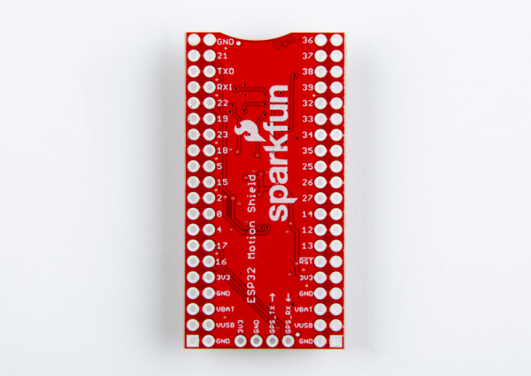
LilyPad E-Sewing ProtoSnap Hookup Guide

$
0
0

LilyPad E-Sewing ProtoSnap Hookup Guide a learn.sparkfun.com tutorial

Available online at: http://sfe.io/t705

Introduction

The LilyPad E-Sewing ProtoSnap is a great way to explore how buttons and switches behave in simple e-sewing circuits before crafting your project. This guide will go over the individual components in the E-Sewing ProtoSnap and how to break it apart to prepare for use in a project. You can follow along with this guide for both the E-Sewing ProtoSnap and E-Sewing ProtoSnap Kit.

LilyPad E-Sewing ProtoSnap

DEV-14546
$4.95
LilyPad E-Sewing ProtoSnap Kit

KIT-14528
$9.95

Suggested Reading

If this is your first sewable electronics project, we recommend you read our LilyPad E-Sewing tutorial.

LilyPad Basics: E-Sewing

December 17, 2016

Learn how to use conductive thread with LilyPad components.

Hardware Overview and Features

Like other LilyPad ProtoSnap series boards, the individual pieces of the board are pre-wired - allowing you to try out the function of the circuit before sewing. The E-Sewing ProtoSnap includes three white LilyPad LEDs: two connected to a LilyPad Slide Switch and one connected to a LilyPad Button Board. A LilyPad Coin Cell Battery Holder with a 3V Coin Cell Battery provides the power for the circuit. These parts are connected together by conductive pathways called traces.

LilyPad ProtoSnap

Required Materials and Tools

If you are using the E-Sewing ProtoSnap Kit, you will also have:

To create a finished project with the E-Sewing ProtoSnap you will also need:

  • Materials listed above (if not using the E-Sewing ProtoSnap Kit)
  • Felt or fabric to stitch your circuit into
  • Pen, marker, or chalk
  • Scissors
  • Hot glue gun (with extra glue)
  • Optional: Craft supplies for decorating (feathers, sequins, buttons, etc.)

Exploring the Sample Circuit

Let’s try out the circuit!

The LilyPad Battery Holder at the corner of the ProtoSnap holds a 20mm CR2032 Coin Cell Battery. With the battery installed, slide switch on the battery holder to the ON position.

Power Switch

Using the LilyPad Slide Switch

The LilyPad Slide Switch has a small switch labeled ON/OFF. When moved to the OFF position, parts inside the switch move away from each other and open the circuit (disconnecting it). The LEDs will not light up. When the toggle switch is moved to the ON position, the two sew tabs on the switch are connected, allowing current to flow through and close the circuit. You should see the two LEDs below the switch light up.

Side by side illustrations: left of current not flowing through the circuit when the slide switch is turned OFF and right of current flowing through circuit when slide switch is turned ON

Using the LilyPad Button

The LilyPad Button Board is also a type of switch. The circuit that is connected to the far right LED is open when the button is left by itself. When you press the button in the middle of the board, it connects the two sew tabs and allows current to flow through. When you let go of the button, the connection is opened again, and the button springs back into place. This button is an example of a momentary switch – it is only active when an action is applied.

This is slightly different from the slide switch, which is an example of a maintained switch, meaning its state remains the same until changed.

Left: Illustration of current not flowing through the button. Right: Illustration of current flowing through the button and circuit to light up LEDs below an illustration of a finger pressing the button

Learn more about buttons and switches in our Switch Basics tutorial.

Stitching into a Project

Ready to sew into a project? First, slide the coin cell battery out of the battery holder and set aside.

Carefully snap apart the connected components on the E-Sewing ProtoSnap panel to prepare for sewing. Discard the non-sewable pieces and scraps. Use a set of pliers or diagonal cutters if you are having trouble snapping the pieces apart. You will end up with six individual LilyPad pieces: the battery holder with battery, three LEDs, button, and switch.

Snapped LilyPad Pieces(https://cdn.sparkfun.com/assets/learn_tutorials/7/0/5/BreakApart.jpg)

Designing Your Project

Sketch on a piece of paper or arrange the LilyPad pieces on your felt or fabric to form your design. At this point, you can recreate the connections the pieces had in the ProtoSnap format or design your own new configuration. Keep in mind that the positive tabs of the LED must connect to the button or switch in order to be controlled by them. The negative tabs of the LEDs should connect back to the negative tab on the battery holder.

LilyPad Light-Up Plush Template circuit diagram

The image above is an example of a project diagram using the E-Sewing ProtoSnap. For instructions and downloadable template, visit the Light-Up Plush tutorial.

When your circuit design is finalized, secure the LilyPad pieces on your project with a small dab of hot glue or fabric glue, making sure not to cover the holes in the sew tabs. Double check the orientation of the LilyPad pieces against your diagram (or template if using a SparkFun design) before gluing.

Hand holding a LilyPad LED and using a hot glue gun to apply glue to the back of the LEDClose up of a finger pressing a LilyPad LED into place on blue felt with another LilyPad LED attached in the background

To help you plan your stitch lines, draw your circuit onto the fabric with chalk or a washable marker.

Close up of hand drawing lines between LilyPad LED sew tabs with a marker on blue felt

After arranging the circuit, carefully connect each LilyPad component together with conductive thread stitching. Each connection between components should be a separate piece of conductive thread and avoid crossing other stitch lines.

If have never sewn with conductive thread this tutorial covers the basics.

LilyPad Basics: E-Sewing

December 17, 2016

Learn how to use conductive thread with LilyPad components.

Troubleshooting

With any electronics project, there are times you will have to troubleshoot if your circuit isn’t working. If your circuit isn’t lighting up, try a new battery or check that your project is switched on. Check your sewing for any loose threads or ends that may be touching other parts of your circuit and causing a short circuit. Learn more about troubleshooting your project in the LilyPad Basics: E-Sewing tutorial.

Example Projects and Templates

Check out the Light-Up Plush project tutorial for step-by-step instructions on using the E-Sewing ProtoSnap in a project.

Light-Up Plush

December 16, 2016

Craft a light-up plush with LilyPad LEDs controlled by pressing a button and sliding a switch in the creature's hands.

Project Templates

Looking for some more project ideas? Below are a few templates to use with an embroidery hoop or making another plush. Click on the button to download and print (2 pages each).


Download Firefly Template


Download Robot Template


Download Space Template


Download Plush Cat Template

Resources and Going Further

For more information about the LilyPad E-Sewing ProtoSnap, check out the resources below:

Here are some more LilyPad sewable electronics projects to try:

Light Up Pennant with E-Textiles

Show your school spirit, geek pride, or fandom with a light up pennant using the LilyTwinkle or LilyPad Arduino.

Night-Light Pennant with LilyMini ProtoSnap

Use the pre-programmed LilyMini ProtoSnap to make an interactive pennant that reacts to ambient light levels.

Illuminated Mask

Use LilyPad LEDs, a switched battery holder, and coin cell battery to make a fun light up mask for your next costume party.

Twinkle Zodiac Constellation

Create a quick and easy piece of e-textile art based on a Zodiac sign using a LilyTiny, LilyPad LEDs, battery holder, conductive thread, and coin cell battery.

Learn more wearable electronics techniques in these resources:

Insulation Techniques for e-Textiles

Learn a few different ways to protect your conductive thread and LilyPad components in your next wearables project.

Planning a Wearable Electronics Project

Tips and tricks for brainstorming and creating a wearables project.

Powering LilyPad LED Projects

Learn how to calculate how many LEDs your LilyPad project can power and how long it will last.

learn.sparkfun.com |CC BY-SA 3.0 | SparkFun Electronics | Niwot, Colorado
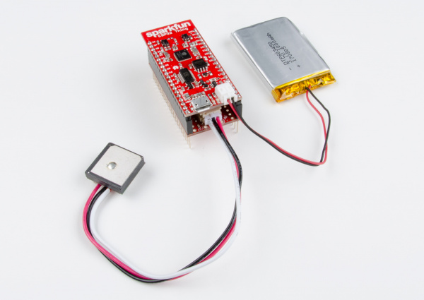
Choosing an Arduino for Your Project

$
0
0

Choosing an Arduino for Your Project a learn.sparkfun.com tutorial

Available online at: http://sfe.io/t720

Introduction

Are you just looking for specs between Arduino boards?

Check out our Arduino Comparison Guide which provides a list of popular Arduino development boards and their specifications.

Let’s face it, there are a a lot of different Arduino boards out there. How do you decide which one you need for your project? In this tutorial, we’ll take a look at the diverse world of Arduino boards. We’ll delve deeper into each board, examining the pros, cons, and example use-cases.

Fistful of Arduinos

Arduino is an open-source electronics prototyping platform based on flexible, easy-to-use hardware and software. It’s intended for artists, designers, hobbyists, and anyone interested in creating interactive objects or environments. Or more simply, you load on some code and it can read sensors, perform actions based on inputs from buttons, control motors, and accept shields to further expand it’s capabilities. Really, you can do almost anything.

All Arduino boards have one thing in common: they are programmed through the Arduino IDE. This is the software that allows you to write and upload code. Beyond that, there can be a lot of differences. The number of inputs and outputs (how many sensors, LEDs, and buttons you can use on a single board), speed, operating voltage, and form factor are just a few of the variables. Some boards are designed to be embedded and have no programming interface (hardware) which you would need to buy separately. Some can run directly from a 3.7V battery, others need at least 5V. Check the chart on the next page to find the right Arduino for your project.

Suggested Reading

If you don’t know what Arduino is but found yourself here, you may want to start with our What is an Arduino tutorial?.

What is an Arduino?

What is this 'Arduino' thing anyway?

You should also have a good understanding of the Arduino IDE. If you need help installing it, visit this tutorial.

Installing Arduino IDE

A step-by-step guide to installing and testing the Arduino software on Windows, Mac, and Linux.

Glossary of Terms

Microcontroller (MCU): The microcontroller is the heart (or, more appropriately, the brain) of the Arduino board. The Arduino development board is based on AVR microcontrollers of different types, each of which have different functions and features.

Input Voltage: This is the suggested input voltage range for the board. The board may be rated for a slightly higher maximum voltage, but this is the safe operating range. A handy thing to keep in mind is that many of the Li-Po batteries that we carry are 3.7V, meaning that any board with an input voltage including 3.7V can be powered directly from one of our Li-Po battery packs.

System Voltage: This is the system voltage of the board, i.e. the voltage at which the microcontroller is actually running. This is an important factor for shield-compatibility since the logic level is now 3.3V instead of 5V. You always want to be sure that whatever outside system with which you’re trying to communicate is able to match the logic level of your controller.

Clock Speed: This is the operating frequency of the microcontroller and is related to the speed at which it can execute commands. Although there are rare exceptions, most ATmega microcontrollers running at 3V will be clocked at 8MHz, whereas most running at 5V will be clocked at 16MHz. The clock speed of the Arduino can be divided down for power savings with a few tricks if you know what you’re doing.

Digital I/O: This is the number of digital input/output (I/O) pins that are broken out on the Arduino board. Each of these can be configured as either an input or an output. Some are capable of PWM, and some double as serial communication pins.

Analog Inputs: This is the number of analog input pins that are available on the Arduino board. Analog pins are labeled "A" followed by their number, they allow you to read analog values using the analog-to-digital converter (ADC) in the ATMega chip. Analog inputs can also be configured as more digital I/O if you need it!

PWM: This is the number of digital I/O pins that are capable of producing a Pulse-width modulation. (PWM) signal. A PWM signal is like an analog output; it allows your Arduino to “fake” an analog voltage between zero and the system voltage.

UART: This is the number of separate serial communication lines your Arduino board can support. On most Arduino boards, digital I/O pins 0&1 double as your serial send and receive pins and are shared with the serial programming port. Some Arduino boards have multiple UARTs and can support multiple serial ports at once. All Arduino boards have at least one UART for programming, but some aren't broken out to pins that are accessible.

Flash Space: This is the amount of program memory that the chip has available for your to store your sketch. Not all of this memory is available as a very small portion is taken up by the bootloader (usually between 0.5 and 2KB).

Programming Interface: This is how you hook up the Arduino board to your computer for programming. Some boards have a USB jack on-board so that all you need to do is plug them into a USB cable. Others have a header available so that you can plug in an FTDI Basic breakout or FTDI Cable. Other boards, like the Mini, break out the serial pins for programming but aren’t pin-compatible with the FTDI header. Any Arduino board that has a USB jack on-board also has some other hardware that enables the serial to USB conversion. Some boards, however, don’t need additional hardware because their microcontrollers have built-in support for USB.

ATmega328-Based Boards

The ATmega328 (and the ATmega168 before that, and ATmega8 before that,…) is a staple of the Arduino platform. 32kB of flash (program space), up to 23 I/Os – eight of which can be analog inputs – operating frequencies of up to 20 MHz. None of it’s specifications are flashy, but this is still a solid 8-bit microcontroller. For many electronics projects, what the 328 provides is still more than enough.

The Arduino boards on this page all feature the ATmega328 as their main MCU brain. The microcontroller alone makes every board on this page nearly identical in terms of I/O count and memory. Their differences stem from things like programming interfaces, form factors, and operating voltages.

The Main Event: Arduino Uno

The Arduino Uno is the “stock” Arduino. It’s what we compare every, other, Arduino-compatible board to. If you’re just getting into Arduino, this is the board to start with.

Arduino Uno

The Uno comes in two flavors, through-hole and SMD, which use either a through-hole or surface-mount ATmega328. The through-hole version (pictured above) is nice because you can take the chip out and swap in a new one (in case the magic, blue smoke is released), but the SMD version has the potential to be more readily available (PTH chips are increasingly being phased out of existence).

The Arduino Uno can be powered through either the USB interface, or an external barrel jack. To connect it to a computer you’ll need a type-B-to-A USB cable (like the USB connector on most printers).

A Modification: RedBoard

One of the greatest things about Arduino is the fact that the entire project is open-source. The schematics, hardware design files, and source code are all freely available for viewing and modification. Released under a Creative Commons Share Alike license, anyone is free to riff on the hardware design and produce their own version. That’s how a product like the RedBoard comes to be. It still looks and acts just like an Arduino Uno, but is slightly modified to make the board better-suited to certain purposes.

RedBoard

The RedBoard is nearly identical to the Uno, but there are a few key differences:

  • USB connector: The Redboard uses the smaller mini-B connector, so you’ll need a mini-B-to-A USB cable to connect it to your computer.
  • USB-to-Serial Transciever: The Arduino Uno uses an ATmega16U4 loaded with custom firmware to convert between USB and serial. The RedBoard uses the FTDI FT232RL. This difference is only really prevalent when installing drivers because each requires a different driver file.
  • SMD vs PTH: The RedBoard is only offered in a SMD version, and it takes SMD a step further by making every component surface-mount. No sharp edges on the bottom of the board!
  • Color: True to it’s name, the RedBoard comes in Ferarri SparkFun red. It won’t have any real influence on the operation of the Arduino, but it certainly affects the board’s swag-factor.
  • Price: Because we manufacture the board in-house, here in Boulder, CO, we can afford to keep the price-tag a tad lower.

Like the Uno, the RedBoard is great for beginners. On the whole, it should offer the same Arduino experience as an Uno might. For a deeper comparison between the RedBoard and Uno, check out our RedBoard vs. Uno tutorial.

RedBoard vs. Uno

August 6, 2013

In this tutorial we discuss the differences and similarities between the RedBoard and the Arduino Uno (SMD and PTH). The development platforms

For the Pros

Arduino Pros are a scaled-down version of the Uno. There’s still an ATmega328 on there, but removed are the connectors and USB-to-serial-converting circuitry. Basically, this is the bare-minimum an Arduino needs to still be an Arduino. As the name would imply, these boards are intended for use by more experienced Arduino-ers.

Arduino Pro

You’ll need more than just a USB cable to program an Arduino Pro; an external board is required to convert USB from your computer to serial that the Arduino understands. There are various boards and cables that can accomplish this task, we recommend the FTDI Basic Breakout.

FTDI Basic

This board mates up to the 6-pin, right-angle connector on the edge of the board. When you’re done programming and ready to stick the board into a project, just unplug the FTDI Basic.

The smaller form factor and absence of connectors means this board can be more custom-tailored to fit into a project. You can solder wires or connectors directly onto the pins you need. Then again, it has the same pin footprint as the Uno, so it’s still shield compatible.

The Pros come in two varieties: 5V/16MHz and 3.3V/8MHz. The 5V/16MHz board runs at the same voltage and speed as the Arduino Uno. The 3.3V/8MHz board is unique, though, because it can operate at a lower voltage. A lower operating voltage makes the board easier to power with batteries (LiPos specifically), but it also means the clock speed has to be turned down. The 3.3V/8MHz board runs at half the speed a regular Arduino Uno…but 8MHz is still pretty darn fast for many applications. You can still turn an LED on and off more than a million times per second!

Of course, if this board is still to big, you can shrink it down even further…

Pro Mini’s

The Mini boards pack all of the remaining punch of the Arduino Pro into a much smaller footprint. Every pin is still broken out (actually, more pins are broken out), they’re just in a very different footprint.

Pro Mini with attached FTDI Basic

An Arduino Pro Mini attached to an FTDI Basic, which provides power and uploads code.

Obviously, these boards aren’t shield-compatible, but they are breadboard-compatible. You can solder male headers into the Pros, and straddle it across the breadboard’s middle strip. The small form-factor also makes them very conducive to embedding into projects (like in the H2O pH Probe).

Like the regular Pro boards, these are offered in 5V/16MHz and 3.3V/8MHz varieties. And you still have to program them with an FTDI Basic.

Etcetera

There are innumerable Arduino-compatible boards out there which make use of the ATmega328. Many, like the Arduino Pros, require an FTDI Basic to receive code, but they add on extra hardware to make them unique. The Arduino Ethernet, where the Arduino Uno and an Ethernet Shield are smashed onto a single board, is a good example of this.

Arduino Ethernet

And, the Arduino Fio too. This board wires up the ATmega328 to an XBee (or XBee-compatible) wireless transceiver, so your Arduino can communicate wirelessly with other devices.

Arduino Fio

The list could go on and on. If you see a board with that recurring, six-pin, serial header, and an ATmega328 doing all of the processing, its specifications probably aren’t all that different from an Arduino Pro.

ATmega32U4_Based Boards

The next step in the Arduino evolutionary chain was merging the USB-to-Serial programming part of the board onto the main MCU. That meant we had to leave the ATmega328 behind – becuase it doesn’t natively support USB – in favor of the ATmega32U4. Aside from the additional USB support, the 32U4 is largely similar to the 328. Both are 8-bit AVRs with 32kB of flash memory, 22-ish I/O lines, ADCs, UARTs, timers, etc.

These ATmega32U4 boards often have the benefit of being cheaper than the ATmega328-based boards – there’s one less costly IC to put on there. They can also do things regular Arduino boards can’t, like emulate a USB keyboard/mouse. On the downside, they can be less reliable, and more difficult to use.

Arduino Leonardo

The Leonardo is the patriarch of all ATmega32U4 Arduino boards. It shares the same form factor and I/O placement (analog, PWM, I2C pins in the same place) as the Arduino Uno, so it remains shield compatible.

Arduino Leonardo

Differences between the Leonardo and the Uno? Aside from the new microcontroller, and lack of a second USB-to-Serial-converting IC, there’s not many. The USB connector is different, the Leonardo connects to a computer via a micro-B USB cable. The driver installation process is also a bit more involved – sometimes it can take a little extra fidgeting to get the board installed on your computer.

Pro Micro

Just as the Pro Mini took the guts of the Arduino Uno and shrunk them down, the Pro Micro works as a miniature version of the Leonardo. Unlike the Pro Mini, the Pro Micro doesn’t require an external board to upload a sketch – the 32U4 takes care of everything!

Pro Micro

The Pro Micro comes in the standard 5V/16MHz operating range or a more unique 3.3V/8MHz variant.

Pro Micros are among the more complicated Arduino boards to get up and running. There are extra steps required to enable them in your Arduino environment, and a misstep can (at least temporarily) “brick” the Pro Micro.

These boards are a good choice if you’re an advanced Arduino-er and have a small USB-oriented project in mind (a mini USB keyboard/mouse?).

More Variants!

There are plenty of other riffs on the Leonardo design as well. There’s the Fio v3, for any Arduino Leonardo project you might want to add an XBee to.

Fio v3

And there are more unique Leonardo-compatible boards, like the MaKey MaKey, which can turn almost anything (from tin foil to Play-Doh to bananas) into a keyboard key.

MaKey MaKey

The ATmega32U4 can make some very cool USB-integrated Arduino projects.

Wearable Arduinos

The e-textiles segment of the Arduino market is ruled by LilyPads. These are identifiable as unique purple, flowery-looking, circular boards. The pins on LilyPads are called “petals”, they have bigger holes and copper filled to the edge of the board. These are designed so conductive thread can be sewn through the holes, and make electrical contact with the exposed copper on the petal.

LilyPad sewn into fabric

LilyPads are great for e-textiles – projects which combine electronics and fabric wizardy. For a detailed explanation of these boards, check out this tutorial.

Choosing a LilyPad Arduino for Your Project

October 27, 2015

Not sure which LilyPad Arduino is right for you? We'll discuss the features of each and help you decide.

More Power!

Need some extra “beef” in your Arduino? Need more I/O pins, or a faster processor? That’s where Arduino’s like the Mega or the Due come into the picture.

Arduino Mega: The Souped Up Uno

The Arduino Mega is what you might get if you packed four Arduino Uno’s into one board. There are 54 I/O pins, instead of the 14 an Uno gives you. That’s a whole lot of extra LEDs! Instead of one hardware serial port, there are four. And the Mega sports a whopping 256 kB of flash program space. Not to mention 16 analog inputs, and 14 PWM outputs. The Mega just has more of everything.

Arduino Mega 2560 R3

The brain of the Mega is an ATmega2560, a fully souped up ATmega328. Aside from the massive processor overhaul, the Mega still shares a lot in common with the Arduino Uno. There’s a secondary IC on-board (an ATmega16U2) to convert USB-to-serial to allow USB programming. It runs at the same speed – 16 MHz. All of the pins are broken out in a way that keeps the board shield-compatible. Because of these similarities, the Mega is a good option for Arduino beginners and experts alike.

If your Arduino project is hitting a wall because you don’t have enough I/O, or if you’re running out of program space, consider stepping up to the Mega.

Arduino Due: Arduino Harder

You thought the Mega was powerful? The Arduino Due is a revolutionary take on the Arduino platform. It sports an entirely different processor architecture – ARM instead of AVR. It’s a 32-bit processor, clocks in at 84 MHz, and has native USB support.

Arduino Due

This thing sports many unique features that other boards don’t have. Stuff like:

  • Two digital-to-analog converters (DACs), which allow the board to output true analog values (instead of PWM). This means you can play audio out it!
  • USB on-the-go (OTG) capability allows the Due to act as both a USB device and a host. So you can hook up other USB devices – like flash drives, WiFi modules, or phones – to the Due.
  • Direct Memory Access (DMA) allows the microcontroller to offload memory-access tasks, so it can perform other operations at the same time.

There are also some new things to watch out for. The Due’s processor – an ATSAM3X8E – can’t work at 5V, so the board only runs at 3.3V This means it may not be compatible with all shields.

The Due has some amazing functionality, but it’s also a more advanced board. It’s not recommended for beginners, but if you have a project that might take advantage of the Due’s unique characteristics, check it out!

Internet of Things!

Arduino Yún

The Arduino Yún has true microprocessor power. It actually runs Linux! It works over WiFi! It’s awesome.

Arduino Yún

The Yún combines an ATmega32U4 (the same MCU on Leonardos) and an embedded Linux machine running the OpenWRT Linux OS. The two processors are “bridged” together. You program the ATmega32U4, just like you program an Arduino Leonardo, over USB. The 32U4 can send commands to the Linux processor, just as you might send commands to your Linux computer in a terminal.

This board is packed full of all sorts of neat features. It can be programmed over-the-air, as long as your computer is on the same WiFi network. It’s designed to easily interact with the Internet, so if your intend on making an “Internet-of-Things”-type project, the Yún may be the perfect Arduino.

Resources and Going Further

Have you picked the perfect Arduino for your project? Looking for more Arduino tutorials? Check these out:

Arduino Shields

All things Arduino Shields. What they are and how to assemble them.

Installing Arduino IDE

A step-by-step guide to installing and testing the Arduino software on Windows, Mac, and Linux.

Data Types in Arduino

Learn about the common data types and what they signify in the Arduino programming environment.

LilyPad Basics: E-Sewing

Learn how to use conductive thread with LilyPad components.

learn.sparkfun.com |CC BY-SA 3.0 | SparkFun Electronics | Niwot, Colorado
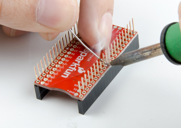
Wireless Audio Bluetooth Adapter w/ BC127

$
0
0

Wireless Audio Bluetooth Adapter w/ BC127 a learn.sparkfun.com tutorial

Available online at: http://sfe.io/t461

Introduction

It all started when my friend and I were running late for a local dance competition. As soon as we arrived, my friend quickly exited the car and grabbed his phone. Without realizing it, he had ripped the audio connector off the cable while it was still connected to his phone. It was at that point that I decided to upgrade my sound system by adding an audio bluetooth.

Wireless Audio Bluetooth Adapter for Car

Required Materials

To configure a BC127, make sure to have these parts:

SparkFun FTDI Basic Breakout - 5V

DEV-09716
$14.95$7.95
100
SparkFun USB Mini-B Cable - 6 Foot

CAB-11301
$3.95
2
Break Away Male Headers - Right Angle

PRT-00553
$1.95
4

To build the wireless audio bluetooth adapter, you will need the following parts. You may not need everything though, depending on what you have and what you want to do. Add it to your cart, read through the guide, and adjust the cart as necessary depending on what you would like.

You will also need:

  • Speakers w/ 3.5mm Audio Jack
  • 3.5mm Audio Cable
  • 5V Car Adapter
  • Cardboard Box

Tools

You will also need:

Suggested Reading

If you aren’t familiar with the following concepts, we recommend checking out these tutorials before continuing.

How to Solder: Through-Hole Soldering

This tutorial covers everything you need to know about through-hole soldering.

Installing an Arduino Library

How do I install a custom Arduino library? It's easy!

Working with Wire

How to strip, crimp and work with wire.

Bluetooth Basics

An overview of the Bluetooth wireless technology.

Understanding the BC127 Bluetooth Module

SparkFun has two boards using the BC127; here's what you need to know to use them.

Configuring the BC127 as Sink

Before I started building the project, I needed to understand the commands to configure the audio bluetooth. The user manual was a little confusing at first so I decided to test the commands using a USB-to-serial converter and a serial terminal. Through testing, I found that the BC127 would somehow re-configure itself as a source bluetooth and it would not accept any new connections. I also did not like having HFP profile turned on when there was an incoming call. I decided to use a microcontroller to automate the commands as soon as I was able to configure these settings:

  • Setting the Bluetooth’s Name
  • Setting as a Sink Bluetooth
  • Become Discoverable
  • Autoconnect with a Previous Paired Device
  • Turning off the HFP

Configuring the BC127 with an FTDI

To configure, a USB-to-serial converter was needed to send serial commands. A 1x6 row of the right angle header was broken off and soldered to the pins to the BC127’s FTDI port.

Configuring BC127 with an FTDI

Once the FTDI was connected to a computer using a mini-B USB cable and the drivers were installed, the commands were tested through a serial terminal set at 9600 baud, 8-data bits, no parity, 1-stop bits, and no flow control.

Restoring the BC127

Just in case, the BC127 was restored to its default state with the commands listed below. In order to send a command, a carriage return was required. Make sure to press “Enter” on a keyboard when typing the commands and the serial terminal was not sending additional characters. The BC127 should respond with an “OK” after each command:

restore
write
reset

Naming the BC127

Next up was setting up the audio bluetooth’s name to make it easier to recognize. I decided to name the bluetooth “BlueTank1750”. To set the name of the BC127 from the default BlueCreation-XXXXXX to a custom name, the manual indicated that a set command needed to be issued with the configuration parameter equal to the new value. The following commands were issued:

set name=BlueTank1750
write
reset

To view if the name has been saved after reset, the following command was issued:

get name

As a result, the BC127 responded with the configuration parameter and value:

name=BlueTank1750

Setting the BC127 as Sink Bluetooth

To ensure that the BC127 was set to sink, the following commands were issued:

set classic_role=0
write
reset

Setting the BC127 as Discoverable

To test the BC127 with a smartphone’s audio bluetooth, the BC127 needed to be set to discoverable by issuing the following command:

DISCOVERABLE ON

Connecting a Source to a Sink Bluetooth

To connect, I found it easier to turn on a smartphone’s source bluetooth and have it scan for bluetooths in range. The BC127 (in this case it was called BlueTank1750) was selected from the list of available bluetooths to pair and connect. Once selected, a 3.5mm audio cable and speaker were connected to the audio jack labeled “Headphone / Line Out”. Using the smartphone’s music player, a track was played. After successfully playing music, I continued on to the next configuration setting.

Setting the BC127 for Auto Connect

To make the bluetooth auto connect everytime it was powered up, the following commands were issued:

set autoconn=1
write
reset

After sending the commands, any smartphone with a “source” audio bluetooth enabled was able connect to the BC127 as a “sink” as long as it was connected previously. The device will remember the bluetooth address and connect to the first audio bluetooth in its vicinity that it remembers.

Since the reset command was issued, the BC127 restarted and automatically searched for the next available bluetooth that it was able to remember. In this case, it was the same smartphone that was used in the previous test.

Turning Off the HFP

The last feature to implement was the configuration of the HFP. To turn off the HFP the following commands were issued:

set enable_hfp=off
write
reset

Hardware Hookup

After configuring the BC127 and testing the BC127, I decided to automate the commands with button presses using a RedBoard programmed with Arduino. The code was written and tested on a breadboard before soldering anything together as shown below:

Purpletooth and Arduino

Soldering the Metal Pushbuttons

Once the code was tested and stable, I decided use panel mount momentary metal pushbuttons. The momentary push bushbutton acts like a normal momentary push button if you connect to the normally open (NO1) and common pin (C1). As a bonus, there are pins labeled “+” and “-” that connect to an LED ring.

alt text

I found that the metal pushbuttons also included a built-in resistor from user emc2, so the 330Ω resistor was not included when soldering to the buttons. Testing with a variable power supply, the LED did not appear to act like a short circuit when 5V was applied. The red LED was also removed since the project would always be connected to a power supply.

ComponentComponent PinArduino I/O Pin
Blue Momentary Metal Pushbutton+ : LED Anode Side9
NC1: Normally Closed Pin
NO1: Normally Open Pin3
C1: Common PinGND
-: LED Cathode SideGND
Green Momentary Metal Pushbutton+ : LED Anode Side8
NC1: Normally Closed Pin
NO1: Normally Open Pin2
C1: Common PinGND
-: LED Cathode SideGND
PurpleTooth Jamboree BC127GNDGND
VIN5V
TXO10
RXI11

To connect the metal pushbuttons to the RedBoard’s female headers, 12" male jumper wires were cut in half and stripped using wire strippers. The exposed wire was threaded and soldered to each metal pushbutton’s pin. To assist in soldering, tape was used to hold down the wire and metal pushbutton.

Soldering Wire to a "-" Pin

An intentional solder jumper was added between the “-” and COM1 pin since both pins needed to be connected to GND.

Intentional Solder Jumper

After testing the connections and LED with a multimeter, the solder joint was sealed with heatshrink using a hot air rework station.

Heat Shrink

Enclosure

Once the parts were soldered together, I wanted to make a quick enclosure. I decided to use a red SparkFun cardboard box to hold and secure the parts.

Using the metal pushbutton's provided hex nut, two circles were drawn on the top of the box.

Draw Metal Pushbutton Hole

Using a coin, an additional hole was drawn for the power and audio cables.

Draw Cable Hole

Using a hobby knife, the holes were carefully cut. There was not a lot of tolerance available for the metal pushbutton's flange. A smaller hole was cut within the circle and adjusted as necessary when installing the metal pushbutton.

Cut Holes

Next up were the mounting holes for the RedBoard and Purpletooth Jamboree. I planned the location for each component and made sure that the components did not interfere with each other when the box was closed. Holes were drawn for the mounting hole locations and created using the “+” side of a mini screwdriver.

Holes for Standoffs

Two screws and a standoff were used for each mounting hole. The mini screwdriver was used to secure the hardware.

Screw Standoff

After braiding the wires and wiring the components together, the metal pushbuttons were mounted and secured with their respective hex nut. This was a good time to add the mini-B USB and audio cable.

Secure metal pushbutton

Before closing the box, I made sure that the wires and components had enough room and were not causing any stress to the connections.

Inside of box

For power, I decided to use a 5V car adapter with a USB port. I made sure to label the buttons and the bluetooth's name before connecting it to my car.

Wireless Bluetooth Adapter for Car

Example Code

Note: This example assumes you are using the latest version of the Arduino IDE on your desktop. If this is your first time using Arduino, please review our tutorial on installing the Arduino IDE. If you have not previously installed an Arduino library, please check out our installation guide.

The code to automate the features requires the SparkFun BC127 Arduino Library. Make sure to download it here:

SparkFun BC127 Arduino Library

The example code used for the wireless audio bluetooth adapater can be found here:

BlueBlock1750v3 Example Code

The code is currently using “BlueBlock1750” as the BC127’s name and the autoconnect was disabled. Make sure to adjust the custom name and autoconnect in the bluetoothReset() function. For my car, I adjusted the name to BlueTank1750 and made autoconn=1. Once the code was adjusted, I uploaded the code to the Arduino.

Connecting Your Source Bluetooth

With the wireless audio bluetooth adapter built, any audio bluetooth set as a source should be able to connect and stream music. Here are some general notes to connect your source’s bluetooth since each device can have different instructions. Most of the time, a smartphone (with a Android and iPhone) is used to connect. Any smartphone or laptop that has an audio bluetooth should be able to connect. In this case, a smartphone was used.

General Steps to Connect

  • Press the “Discoverable” button on the BC127.
  • Turn on your device’s source bluetooth.
  • Scan for the wireless audio bluetooth adapter from your settings.
  • Select the BC127’s and begin pairing.
  • Once paired, connect to the BC127.
  • Open your music player app.
  • Choose your favorite track or mixtape and hit play.
  • Turn the volume up to safe levels on the speaker and phone once the music starts!

Stress Tests in the Field

After the first build, I decide to built two more adapters! Here are some quick notes on the different builds using the initial connection diagram.

High Volume of Users and Range

One of the adapters was donated to a local dance studio called Block 1750 to make it easier for users to connect to the studio speakers. A blue, big dome pushbutton replaced the blue metal push button as shown in the image below. The autoconnect seemed to cause confusion users connecting throughout the day so I decided to disable the feature in the Arduino’s code. Depending on the smartphone being used, the range varied for the bluetooth connection. Some would work as far as the other end of the studio (about 40 feet line of sight). Other devices would work within a few feet. The BC127 seemed more reliable when it was within 4 or 5 feet away. The image below shows a user streaming music to the wireless bluetooth adapter.

User Connected to Bluetooth and DJing

The big dome pushbutton installed on the wireless bluetooth adapter and a user streaming music from his smartphone.

Going Portable

Since I also teach dance at different locations, I decided to make it a portable wireless bluetooth adapter. In addition to the original design, a 1000mA rechargeable LiPo battery was included to make use of the BC127's LiPo charging feature. A red latching metal pushbutton was also connected between the battery and VIN so that power could be removed when not in use. I had a 5V step up converter attached to the 5V Arduino Pro Mini and solderable breadboard. With this setup, the adapter can stream music for about 3 hours before the next charge.

Inside the Portable Bluetooth Adapter

Jam On!

Since 2016, all three bluetooths have been working great with amazing quality! The cardboard boxes holding the electronics have also withstood the test of time.

All three wireless audio bluetooth adapters

Troubleshooting

There were some issues that I ran into when trying to configure the BC127 and testing the BC127 initially. Below are a few tips for those that are using a BC127 audio bluetooth in a project.

BC127 Output Error and Not Connecting to a Source Bluetooth?

If you are seeing this error with your BC127:

OPEN_ERROR AG
OPEN_ERROR AG

, it’s possible that the BC127 has somehow been set to source mode instead of sink mode. This can happen randomly or if you press and hold the momentary push button labeled VREGEN“long” on the Purpletooth Jamboree. BlueCreations defines a long as holding it down for 1000ms or more. Resending the commands should fix the issue:

set classic_role=0
write
reset

Auto Connect After the BC127 is Turned on

If the BC127 has been turned on before your smartphone’s bluetooth is enabled, try hitting the RESET button to power cycle the BC127 so that it can re-scan through its saved list of previously paired devices. You can also power cycle or send the reset command.

Resources and Going Further

For more information on the Purpletooth Jamboree and the BC127 module, check out these documents:

For more tutorial action, check out these related links:

RN-52 Bluetooth Hookup Guide

A hookup guide to get you started with the RN-52 Audio Bluetooth Module Breakout Board.

Interactive Hanging LED Array

Learn how we converted 72 lightbulbs into an interactive LED array for our conference room.

learn.sparkfun.com |CC BY-SA 3.0 | SparkFun Electronics | Niwot, Colorado
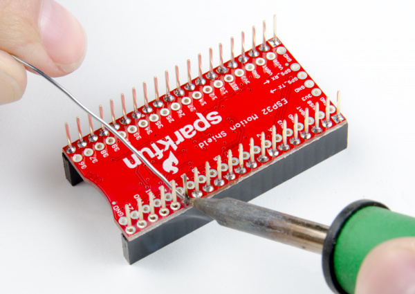
Getting Started with TJBot

$
0
0

Getting Started with TJBot a learn.sparkfun.com tutorial

Available online at: http://sfe.io/t707

Introduction

TJBot is a kit developed at IBM to help people get started with their Watson AI service. It comes with a friendly little robot that you build yourself, a Raspberry Pi 3, and all the parts you need to make your robot wave, blink, talk, and listen.

IBM TJBot, a Watson Maker Kit

KIT-14515
$125.00

Required Setup Tools

As a desktop, these devices are required:

Getting Started

Before you do anything else, we recommend setting up your Raspberry Pi, connecting it to the Internet, and updating the OS. Here we’ll help you out with that.

Setting up the Pi

Connect up your monitor, keyboard, and mouse as you would with any computer. Insert the microSD card that came with the TJBot kit and then plug in the power supply. There’s only one place that the power supply can physically be plugged in: the micro-B USB connector labeled “PWR IN”. Again, we recommend our 5.1V Micro USB power supply to power your TJBot.

After powering up and letting the Pi boot, you should have an image on the screen that looks something like this:

Pi screen on boot

Users in the United States may want to change the keyboard layout from UK to US, as the UK layout has some keys in places that you wouldn’t expect. To do that, open the Raspberry menu, select “Preferences”, then “Mouse and Keyboard Settings”.

Mouse and keyboard settings location

Under the “Keyboard” tab, you’ll find a button called “Keyboard Layout…”. Find your preferred keyboard layout in the window that pops up when you click that button.

Install TJBot

Installing TJBot is done with one script which can be run with one command. The command is:

curl -sL http://ibm.biz/tjbot-bootstrap | sudo sh -

Copy that line and paste it into a terminal window. Open a terminal window by clicking on the button in the bar at the top of the screen highlighted in the image below.

Terminal window

Once you have pasted this line of code into the terminal window, hit the Enter key on the keyboard. That will pull the latest version of the TJBot Bootstrap script from the Internet. You’ll get a window that looks something like this:

TJBot first prompt

Presumably, you’re running on the Raspberry Pi you want TJBot installed on, so type ‘y’, then hit Enter.

You’ll be prompted to enter a name for your TJBot. Feel free to name the TJBot anything you wish, or just hit Enterto leave it unchanged. It really doesn’t matter, I promise.

You’ll then be asked if you wish to disable ipV6. Again, type ‘y’ and hit Enter.

The next question is whether to use Google’s nameservers to speed up DNS queries. Again, hit ‘y’ and then Enter.

Then, the script will ask you if you wish to “force locale” to US English. You may answer yes or no to this question as you will, but if you’re a user in the US, it makes sense to answer yes.

Upgrade the OS on the Raspberry Pi

You should now have a prompt that looks like this:

upgrade prompt

The script is asking a somewhat scary sounding question about upgrading your Raspberry Pi’s operating system. It warns that this could take an hour or longer (GULP)! Don’t worry, in our experience it takes about ten minutes or less depending on the speed of your Internet connection. In any case, you’ll want to type ‘y’ again, then hit Enter to begin the update process. Keep an eye on the screen as the upgrade process runs, but you don’t need to monitor it closely as the entire upgrade process is automatic. Screen after screen of text will scroll past during this process, and you don’t need to worry about any of it.

Install Node.js

After the upgrade process is complete, you’ll have this prompt, asking you about installing a newer version of Node.js.

Prompt for node install

Again, answer yes to this question. Immediately after answering yes, you’ll be asked which version of Node.js to install (6 or 7). Type ‘7’, then hit Enter. You’ll get another few screens of text as the script downloads and installs Node.js version 7 to your Raspberry Pi.

After Node.js is installed, the script will ask if you have a camera installed. If you didn’t purchase a camera, answer no, as a camera doesn’t come with the TJBot kit.

The next question is regarding “cloning” the TJBot project, and where that should be cloned to. Cloning in this case really just means downloading. The default location for downloading is to the desktop, which is as good a place as any and better than many. So just hit the Enter key to download the TJBot project to the desktop.

You’ll now have a screen that looks as below.

Desktop Screen

The script is asking “Disable sound kernel modules?” As the TJBot kit from SparkFun uses the audio jack for sound output instead of the HDMI or USB output options, you’ll want to hit ‘n’ here. If you answer ‘yes’ to this question, audio won’t work on later TJBot projects and you’ll be sad.

Cloning the TJBot project

Finish up!

You’ll now be treated to an ASCII art rendering of TJBot’s face, a message saying that setup is complete, and an invitation to hit Enter to continue. Go ahead and hit Enter.

You’ll now get a screenful of text about signing up for a free IBM Bluemix account, how to log in, create instances of services, get credentials, and other things as well! We are just going to ignore it for now, because we’re going to walk you through all the steps in that window on the next pages.

Finally, you’ll be asked if you want to run hardware tests. I suggest answering ‘no’ as some of the changes we made during the install process may cause these tests to fail even though nothing is wrong.

The last question is: “Do you want to reboot now?” You can answer ‘yes’ for an immediate reboot, or ‘no’ and reboot later. I recommend just going ahead and answering ‘yes’.

IBM Cloud

TJBot’s magical powers come from Watson, IBM’s artificial intelligence service. In order to use Watson, you’ll need to create a free IBM Cloud account.

We’ll now walk you through signing up for a IBM Cloud account.

Sign Up for an IBM Account

You’ll need to go to this website to sign up for an IBM account. You’ll then be able to use the IBMid you create to log into the IBM Cloud website.

IBM ID creation page

Fill in the blanks to create an account, then check your email. You should have a new message from IBM with a 7-digit confirmation code. Enter the code in the field as shown below.

confirmation code page

Once you’ve entered your confirmation code, you’ll be taken to your IBM account dashboard. The only thing to do here is to log out using the menu in the upper right, as shown below.

log out

Log In to IBM Cloud

Now you can log into the IBM Cloud website. Follow this link to the IBM Cloud registration page.

Heads up! For the rest of this tutorial, you may see the term "Bluemix" in some images. This is the older name for the IBM Cloud. Everything else should be the same, just mentally substitute "IBM Cloud" for "Bluemix", okay?

IBM Cloud signup page

Put in the email address that you used for your IBMid and hit Enter. You’ll be asked to provide a phone number.

Signup step 2

After you click “Create Account”, you’ll be asked to complete an anti-spambot captcha, and then you’ll be taken to this page:

IBM Cloud success

You’ll get an e-mail shortly with an account confirmation link, as pictured below.

confirmation email

Click on the “Confirm Account” button to let IBM’s Cloud team know you’re a real person. That will open this page:

bluemix success 2

Click the blue “Login” button to be automatically logged into IBM Cloud.

Set Up IBM Cloud

You’ll now be asked to “Name your organization”. This doesn’t really matter and feel free to call it whatever you like, but it’s a good idea to keep it short and easily typable for later usage.

Create org page

Once you’ve created your organization, you’ll need to create a space. Again, the name doesn’t really matter. I went with “test”.

Create space

You’ll now be notified that your account is “Good To Go!” and be given a summary of the organization and space names you just created.

Summary

Click on the “I’m Ready” button.

The IBM Cloud Dashboard

Once the IBM Cloud is setup, you will be greeted with the IBM Cloud Dashboard after logging in as shown in the image below.

The IBM Cloud Dashboard

This is where you’ll start out when you log in to your IBM Cloud account from now on. The last step we need to complete is to set up the payment information so we can access the paid services we need to make TJBot come alive.

Start by selecting the “Billing” option under the “Manage” menu in the upper right corner of the dashboard, as seen below.

Billing

That will bring up this page. Click the “Add Credit Card” button in the middle of the page.

Upgrade info page

You’ll be presented with this fairly standard billing information form. Fill it out and submit it.

Billing info

You should now be the proud owner of an upgraded IBM Cloud account. You are now ready to complete the next steps of the tutorial. Now, let’s have some fun with TJBot!

Voice Control an LED

Our first project is to set up TJBot to voice control an addressable LED. To begin, we need to hook up the LED to TJBot.

LED Hookup

Start by finding one of the LEDs included in the TJBot kit. It should look like the picture below and be about the size of a pencil eraser.

LED picture

Diagram courtesy Maryam @ IBM

You now need to connect this LED to the Raspberry Pi. Find the F/F jumper wires that were included in your kit, and follow the diagram below to hook up the LED.

Wiring diagram

Diagram courtesy Maryam @ IBM

USB Microphone Hookup

Now is the time to plug the USB microphone into one of the USB ports on the Raspberry Pi. It doesn’t matter which port you plug it into, just plug it in.

Set up a Speech-to-Text Instance on IBM Cloud

Go back to the IBM Cloud dashboard and click on the hamburger menu (Did you know this is called a hamburger menu? You learn something new every day!) in the upper left corner.

hamburger menu

A menu will pop out of the left edge of the page. Find the entry for “Watson” in this menu (it’s down near the bottom, and you may need to scroll to find it) and click on it.

Watson entry

You’ll be told that you don’t have any Watson service instances yet, and be invited to create one. Click on the “Create Watson service” button.

create Watson service

That will bring up this page, with a list of all available Watson services.

Watson Services

Click on the “Speech to Text” section to bring up this page of setup options.

STT page

All you need to do here is click the “Create” button and you’re in business. The default values can be left in place.

You’ll be brought to this page. We’re going to need to fetch the credentials for our “Speech to Text” instance, so click “Service credentials” along the left edge of the page.

STT next page

That will bring up this page. To see your credentials, click on the “View credentials” drop down in the middle of the page under the ACTIONS.

STT Credentials

Copy the Credentials into the Raspberry Pi Config File

Now we need to copy those credentials into a file on the Raspberry Pi. If you haven’t been working on the Raspberry Pi up to this point, it’s probably easiest just to be logged in on the Pi and open the IBM Cloud website on the Pi’s web browser.

The file you need to modify is located in “Desktop/tjbot/recipes/speech_to_text” and it’s called “config.default.js”. Double clicking the file will open it in the text editor. You can then copy and paste in the new information.

Config.default.js file

Copy and paste the “username” and “password” from the webpage into the text document. Note that the order of the two is swapped! On the webpage, username is above password, but in the text doc, it’s password above username. Once you’ve entered the information, you need to “Save as…” the document to change its name. The new name is “config.js”. You must do this or the recipe will fail.

Install and Run the Speech to Text Example

Now, open a command line on the Pi and run the following commands:

cd Desktop/tjbot/recipes/speech_to_text
npm install
sudo node stt.js

The npm install step will take some time to complete. Once you issue the node stt.js command, you’ll see this:

STT running

You can now issue commands to TJBot to change the color of the LED, such as “Turn the light red”, “Turn the light blue”, or “Turn the light off”. Pretty nifty, huh? Try out the voice commands to change the color of the LED.

When you’re done, just hit ctrl+C to quit the script.

Sense the Tone of Twitter

Our next project uses Watson’s Tone Analyzer to analyze recent tweets and get a sense of the overall emotional tone of them.

Create a Tone Analyzer Instance

Repeat the steps used on the previous page to create a “Speech to Text” instance with the “Tone Analyzer” service. Again, leave the default values in place and hit “Create”.

Next, repeat the steps used to fetch the credentials from the IBM Cloud website and insert them into the file on the Raspberry Pi. This time, you’ll find the “config.default.js” file in “Desktop/tjbot/recipes/sentiment_analysis”. However, don’t close it when you’re done with this step.

Create a Twitter App to Access Recent Tweets

You’ll need a Twitter account for this step, so go to Twitter and sign up for one if you don’t already have one.

Now go to the Twitter apps site and log in. You should end up on a page that looks like this:

Twitter apps page

Click the “Create an app” button to be taken to the page seen below. Fill in the blanks as you see fit (note that the application name must be unique, so you can’t reuse “TJBot”), click the checkbox, and then click the “Create your Twitter application” button.

Create an app page

You’ll then be presented with this page, detailing some information from the creation process.

Created app

Right beneath the name of your app (in big bold letters at the top of the page) you’ll see a tab titled “Keys and Access Tokens”. Click on this to bring up this page:

Keys and access tokens

Now we need to grab a couple of pieces of information from this page for pasting into the config file we opened up above. As you can see below, there are four pieces of Twitter-related information that we need to collect. We’ll start with the “consumer_key” and “consumer_secret”. Both of these have the same name on the website as they do in the config file; copy and paste them from the website into the config file.

Twitter info to collect

Next we’ll need to get the “access_token_key” and “access_token_secret” fields. To do that, scroll down on the webpage until you see the “Create my access token” button. Click it and you’ll get this screen:

Access tokens

Copy and paste the “access_token_key” and “access_token_secret” into the config file. Then “Save As…” the file and name it “config.js”. You’re ready for the next step!

Launch the App!

It’s time to check out the recipe in action! As before, open a terminal window on the Raspberry Pi and type out these commands:

cd Desktop/tjbot/recipes/sentiment_analysis
npm install
node sentiment.js

Remember, the npm install step will take some time to run, so be patient. After you run the node sentiment.js step, you should have a screen that looks like this:

sentiment.js run

It’ll take a few moments for the app to gather enough tweets (at least 100) for it to run the Tone Analyzer, but when it does, it will print out a line stating the current emotion surrounding the keyword it is searching for, as well as changing the LED color.

When you’re done, just hit ctrl+c to quit the script.

Have a Conversation with TJBot

The last recipe we’ll explore uses the “Conversation” service and “Text to Speech” service to make TJBot at least minimally able to talk to us.

Speaker Hookup

At this point, we’ll want to connect our mini-speaker to the Raspberry Pi. As with the power supply, there’s only one place that the speaker can be connected. You may, if you choose, connect the charge cable for the speaker to a USB port on the Raspberry Pi, to ensure that the speaker will operate and remains fully charged.

Create Watson Services

As in the last two recipes, we’ll need to create an instance of the “Conversation” and “Text to Speech” services. We’ll also use the “Speech to Text” service we created for the first recipe. We’ll need to fetch credentials for these various services and put them into, you guessed it, a config file on the Raspberry Pi. This time, you’ll find the “config.default.js” file under “Desktop/tjbot/recipes/conversation”. Open it in the text editor.

Start with the “Speech to Text” service. You can either return to your dashboard and click on the name of the service to bring up the familiar page with “Service credentials” on the left edge, or you can copy the credentials from the config file created for the first recipe.

Now, create a “Text to Speech” instance, following the same method you used to create instances in the first two recipes. Once more, you can leave the default values in place and just hit “Create”. Copy the credentials into the text document.

Finally, create a “Conversation” instance. This one is a little more complicated. For the first portion, it works the same as the three other services we created, so just follow those steps again and copy the credentials into the text document. Default settings will once again suffice.

The last vital piece of information we need is the conversation workspace ID. Find the blank for this near the top of the text file, just above the credentials area for the Watson “Conversation” service. To acquire this, go to the IBM Watson Conversation website and log in with the same ID you used for the IBM Cloud website. Make sure you do this on the Pi’s web browser. After logging in, you’ll see this page:

Watson Conversation Workspaces website

We need to upload a file, but first, we need to create a new workspace. Click on the “Create” button, then name your workspace (it doesn’t matter what you call this one) and again click the “Create” button. That will take you to this page. Click on “Watson Conversation” at the top of the page to go back to the main Watson Conversation Workspace page.

New workspace

You’ll be back at the main page. Click on the little “Upload” button (the half rectangle with the arrow pointing up) next to the “Create” button. If you hover over the button with your mouse’s pointer, a text box will pop up with the words “Import workspace” as shown below.

Upload file from this page

Clicking on that button will bring up this window. Click on the “Choose a file” frame and find the file “Desktop/tjbot/recipes/conversation/workspace-sample.json”. Leave the “Everything” radio button highlighted, then click “Import”. That will get you to this page:

Imported workspace

Click on “Watson Conversation” at the top of the page to go back to the main Watson Conversation Workspace page again.

Where to find the workspace ID

Click on the three vertically aligned dots in the “TJBot Conversation” frame and choose “View Details”. The contents of the frame will change; scroll down in the frame to find the Workspace ID, which is the final piece of information we need to get this recipe working! Copy it from this webpage to the text document, “Save as…” the document to the name “config.js”, and close it.

Launch the Application

This part should look very familiar. Open a terminal window on the Raspberry Pi and type in these three commands:

cd Desktop/tjbot/recipes/conversation
npm install
node conversation.js

Again, wait for npm install to complete. After you input the node conversation.js command, you’ll see this:

Watson conversation running

Try to start a conversation with the TJBot by using commands like “Watson, tell me a joke” or “Watson, who are you?” There aren’t too many things you can ask for, but experiment with different ways of asking (for instance, “Watson, let’s hear a joke” works just as well as “Watson, tell me a joke”). Explore the power of the language processing that Watson can do.

When you’re done, hit ctrl-c to quit the script.

Resources and Going Further

Now that you’ve successfully got your TJBot up and running, it’s time to incorporate it into your own project!

For more information, check out the resources below:


learn.sparkfun.com |CC BY-SA 3.0 | SparkFun Electronics | Niwot, Colorado
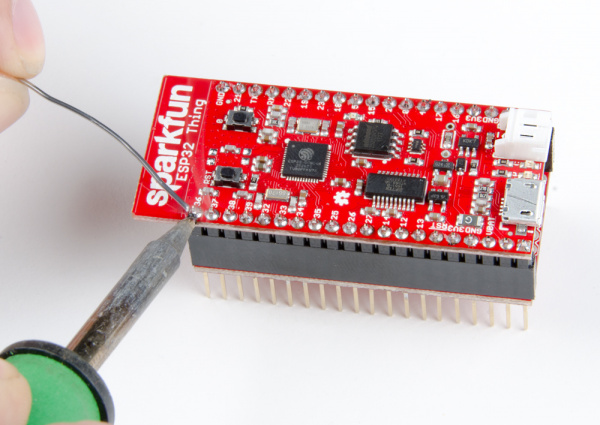
Clap On Lamp

$
0
0

Clap On Lamp a learn.sparkfun.com tutorial

Available online at: http://sfe.io/t715

Introduction

Perhaps you remember an “As Seen on TV” product known as “The Clapper” in the 1980s and 1990s. The TV commercials could be seen on almost every channel. The premise was simple: a 120 VAC relay would control power to appliances and respond to two sharp noises, specifically two claps. We’re going to make our own version of this, but instead of controlling any appliance, we will operate a lamp chain using a servo.

Required Materials

You can complete this project with parts from the SparkFun Inventor’s Kit v4.0 and a Sound Detector board. Specifically, you will need:

Tools Needed:

Suggested Reading

If you aren’t familiar with the following concepts, we recommend checking out these tutorials before continuing:

What is an Arduino?

What is this 'Arduino' thing anyway?

Installing Arduino IDE

A step-by-step guide to installing and testing the Arduino software on Windows, Mac, and Linux.

Hobby Servo Tutorial

Servos are motors that allow you to accurately control the rotation of the output shaft, opening up all kinds of possibilities for robotics and other projects.

SparkFun Inventor's Kit Experiment Guide - v4.0

The SparkFun Inventor's Kit (SIK) Experiment Guide contains all the information needed to build all five projects, encompassing 16 circuits, in the latest version of the kit, v4.0.

Hardware Assembly

Lamp Assembly

To start, we’ll attach the servo to the lamp first. If you want to protect your lamp’s finish, wrap some electrical tape around the post, covering about a 3-inch section.

Wrapping electrical tape around lamp

Use a screwdriver to tighten the hose clamp around the post about 1 inch above the base. Note that you may need to adjust the position of the servo later so that it can effectively pull the chain. Leave a small gap on one side.

Attaching hose clamp to lamp

Thread two zip ties through the gap in the hose clamp

Pulling zip ties through hose clamp

Carefully pull the zip ties around the servo on either side of the flange. Pull the zip ties tight (you may need to use a set of needle-nose pliers).

Pulling zip ties through hose clamp

Tighten the hose clamp as needed and cut the ends of the zip ties.

Cut ends of zip ties

Using a screw, attach a servo arm to the servo’s shaft. Make sure that the arm can rotate from pointing directly up to directly down, rotating away from the lamp’s post. We’ll use that motion to pull the lamp’s chain.

Put servo arm on servo

Straighten out a paper clip, and bend a hook in one end using needle-nose pliers.

Bending paper clip

With the servo arm facing up, thread the hook through the outermost hole in the servo arm. Hold the other end of the paper clip up to the chain, and bend the paper clip so that it hooks onto the chain.

Attach other end of paper clip to chain

Try rotating the servo to make sure that the chain is pulled fully to switch the lamp. This may require readjusting a second paper clip hook so that the chain is pulled successfully on each rotation.

Make sure that the servo pulls the chain

Circuit Diagram

Using jumper wires, connect the components as shown in the diagram below.

Clap on lamp Fritzing diagram

Having a hard time seeing the circuit? Click on the image for a closer look.

Programming

Note: This example assumes you are using the latest version of the Arduino IDE on your desktop. If this is your first time using Arduino, please review our tutorial on installing the Arduino IDE.

Copy and paste the following code in the Arduino IDE. Click Upload to send your compiled code to the Arduino.

language:c
/**
 * Clap On Light
 * Date: November 9, 2017
 * Author: Shawn Hymel (SparkFun Electronics)
 *
 * Connect a servo to a lamp chain/switch to turn it on and off
 * with two successive claps (or other loud noises).
 *
 * To complete this project, you will need parts from the
 * SparkFun Inventor's Kit v4.0:
 * https://www.sparkfun.com/products/14265 as well as a sound
 * detector board: https://www.sparkfun.com/products/14262 along
 * with a lamp, electrical tape, hose clamp, zip ties, and a
 * paper clip.
 *
 * This sketch was written by SparkFun Electronics, with lots of
 * help from the Arduino community. This code is completely free
 * for any use.
 */

#include <Servo.h>

// Pins
const int SERVO_PIN = 9;
const int SOUND_PIN = A0;

// Constants
const int THRESHOLD = 30;                           // Raw ADC
const unsigned long TIMEOUT = 500;                  // ms
const unsigned long TIME_BETWEEN_PULSES_MIN = 300;  // ms
const unsigned long TIME_BETWEEN_PULSES_MAX = 1000; // ms
const int PULSE_MIN = 40;                           // ms
const int PULSE_MAX = 300;                          // ms
const int SERVO_WAIT = 1000;                        // ms
const int SERVO_CCW = 0;                            // deg
const int SERVO_CW = 180;                           // deg

// Globals
unsigned long last_pulse_time = 0;
Servo servo;

void setup() {

  Serial.begin(9600);

  servo.attach(SERVO_PIN);
  servo.write(SERVO_CW);

  pinMode(SOUND_PIN, INPUT);
}

void loop() {

  // Look for pulse and take time it occured
  unsigned long pulse_length = readPulse(SOUND_PIN, THRESHOLD, TIMEOUT);
  if ( (pulse_length >= PULSE_MIN) &&
       (pulse_length <= PULSE_MAX) ) {
    unsigned long pulse_time = millis();
    Serial.println(pulse_time - last_pulse_time);

    // Check time between this pulse and the last one we saw
    if ( (pulse_time - last_pulse_time >= TIME_BETWEEN_PULSES_MIN) &&
         (pulse_time - last_pulse_time <= TIME_BETWEEN_PULSES_MAX) ) {
      Serial.println("Clap on!");
      pullChain();
    }

    last_pulse_time = pulse_time;
  }
}

// If the analog value is above the threshold, wait for it to
// drop below the threshold and return the time it was above
// the threshold. Return 0 if it's not above the threshold, and
// return the timeout value if it stays above the threshold for
// too long.
unsigned long readPulse(int pin, int threshold, unsigned long timeout) {

  unsigned long t = 0;

  // If above the threshold, wait for value to drop below it
  if ( analogRead(pin) >= threshold ) {
    unsigned long timestamp = millis();
    while ( (analogRead(pin) >= threshold) &&
            (millis() < timestamp + timeout) );
    t = millis() - timestamp;
  }

  return t;
}

// Pull the lamp chain by moving the servo far counterclockwise,
// wait 500 ms, and then move it far clockwise.
void pullChain() {
  servo.write(SERVO_CCW);
  delay(SERVO_WAIT);
  servo.write(SERVO_CW);
  delay(SERVO_WAIT);
}

What You Should See

Clap twice near the sound detector with a pause of about ½ second between claps. The servo should activate and pull the chain to switch the light on. Clap twice again, and the lamp should turn off.

Clap twice to switch the lamp!

Resources and Going Further

The example code and circuit diagram for the Clap On Lamp project can be found on GitHub.

Challenges

  1. Right now, the program looks for any two sharp, successive noises. This could mean tapping the table near the sensor, sneezing or even just talking. See if you can modify the code to be more restrictive about what’s considered a “clap.” Can you have the servo activate only on clap sounds?
  2. Replace the sound detector sensor with another sensor, like a photocell. Have the lamp activate whenever another type of threshold is reached, such as getting too dark in a room.
  3. Write a computer program that looks for the local sunrise and sunset data on the internet and sends a command to the Arduino (e.g., over Serial) to turn the light on at sunset and off at sunrise.

Need some inspiration for your next project? Check out some of these related tutorials:

Mario the Magician's Magical Lapel Flower

A guest tutorial from the astonishingly talented Mario the Magician showing how to put together your own servo-controlled lapel flower.

Spectacle Example: Super Mario Bros. Diorama

A study in building an animated diorama (with sound!) using Spectacle electronics.

learn.sparkfun.com |CC BY-SA 3.0 | SparkFun Electronics | Niwot, Colorado
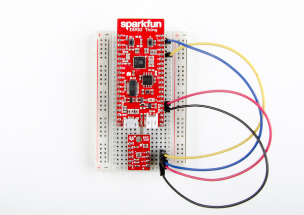

H3LIS331DL Accelerometer Breakout Hookup Guide

$
0
0

H3LIS331DL Accelerometer Breakout Hookup Guide a learn.sparkfun.com tutorial

Available online at: http://sfe.io/t698

Introduction

The H3LIS331DL is a high-g accelerometer with I2C and SPI interface options. It offers an adjustable output range of 100, 200, or 400g, and an adjustable data rate of up to 1kHz.

SparkFun Triple Axis Accelerometer Breakout - H3LIS331DL

SEN-14480
$9.95

Required Materials

Please check the wish list below for items required to follow this tutorial.

Tools

No special tools are required to follow this tutorial. You will need a soldering iron, solder, and general soldering accessories.

Soldering Iron - 30W (US, 110V)

TOL-09507
$9.95
6
Solder Lead Free - 15-gram Tube

TOL-09163
$3.50
2

Suggested Reading

We suggest reviewing the tutorials below to ensure that you’re up-to-date with all of the skills necessary to follow this hookup guide.

How to Solder: Through-Hole Soldering

This tutorial covers everything you need to know about through-hole soldering.

Installing an Arduino Library

How do I install a custom Arduino library? It's easy!

Serial Peripheral Interface (SPI)

SPI is commonly used to connect microcontrollers to peripherals such as sensors, shift registers, and SD cards.

Logic Levels

Learn the difference between 3.3V and 5V devices and logic levels.

I2C

An introduction to I2C, one of the main embedded communications protocols in use today.

Hardware Overview

The H3LIS331DL breakout is fairly simple.

H3LIS331DL Sensor IC - This is the sensor IC. Its operating voltage only extends up to 3.6V, so to use it with a 5V Arduino or Arduino clone, you’ll need some kind of voltage translation! It is perfectly centered on the PCB.

Chip, highlighted

I2C Pull-up Resistors - The board includes pull-up resistor so you don’t need to add them externally.

I2C Resistors Highlighted

I2C Pull-up Resistor Isolation Jumper - If necessary, the I2C pull-up resistors can be removed from the circuit by removing the solder from this jumper.

I2C Resistor Jumper Highlighted

SparkFun Standard I2C Header - Most boards which can be communicated to via I2C use this pinout, making it easy to stack them or connect them in a daisy chain.

I2C Header Highlighted

SA0 Jumper - Closing this jumper changes the I2C address of the sensor from 0x19 to 0x18.

SA0 Jumper Highlighted

CS Jumper - Removing the solder from this jumper enables SPI mode. When the part’s CS line is low at boot, it enables SPI mode.

CS Jumper Highlighted

Interrupt Pins - These pins are tied to interrupts that can be setup by the software library to trigger on various conditions.

Interrupt pins highlighted

SA0 Pin - When the chip is in SPI mode, this goes from being the address select pin to being the MISO pin.

SA0 Pin Highlighted

CS Pin - Chip select for SPI mode. Unused in I2C mode.

CS Pin Highlighted

Library Overview

Here’s a list of the functions supported by the Arduino library for the LIS331 family.

begin(comm_mode mode) - Sets the communications mode to be used by the library (LIS331::USE_I2C or LIS331::USE_SPI), sets the power mode to normal, enables the axes, sets the sampling rate to 50Hz, and resets all the other registers to 0.

setI2CAddr(address) - Sets the I2C address. By default this is going to be 0x19. If the SA0 jumper is soldered closed, it is 0x18. This function must be called before begin() so the library knows what address to use for communications.

setSPICSPin(pin) - Sets the SPI mode chip select pin. This function must be called before begin() so the library knows which pin to use for communications.

axesEnable(bool enable) - Pass true to enable the axes or false to disable them.

setPowerMode(power_mode pmode) - Sets the power mode of the chip. This affects the data rate as well. Options are:

  • LIS331::POWER_DOWN - Minimizes chip power usage but no data or communications are possible
  • LIS331::NORMAL - Normal power mode. Data rate is set by the setODR() function.
  • LIS331::LOW_POWER_0_5HZ - Low power mode, 0.5Hz data rate.
  • LIS331::LOW_POWER_1HZ - Low power mode, 1Hz data rate.
  • LIS331::LOW_POWER_2HZ - Low power mode, 2Hz data rate.
  • LIS331::LOW_POWER_5HZ - Low power mode, 5Hz data rate.
  • LIS331::LOW_POWER_10HZ - Low power mode, 10Hz data rate.

setODR(data_rate drate) - Sets the data rate for the part, when in normal power mode only. Options are:

  • LIS331::DR_50HZ - Set the data rate to 50Hz.
  • LIS331::DR_100HZ - Set the data rate to 100Hz.
  • LIS331::DR_400HZ - Set the data rate to 400Hz.
  • LIS331::DR_1000HZ - Set the data rate to 1000Hz.

readAxes(int16_t &x, int16_t &y, int16_t &z) - Pass three int16_t variables to this function and those variables will be populated with the appropriate value from the accelerometer.

convertToG(maxScale, reading) - Converts from raw data to an actual g-reading. The first parameter is the maximum reading for the current mode, as set by the setFullScale() function. Options are 6/12/24g for the LIS331HH and 100/200/400g for the H3LIS331DL.

setHighPassCoeff(high_pass_cutoff_freq_cfg hpcoeff) - Set the coefficient for the high pass filter. The actual cutoff frequency is dependent upon the data rate set by setODR(). The cutoff frequency is (fs)/(6*Hpc), where fs is the sampling frequency and Hpc is the high pass coefficient as set by these constants:

  • LIS331::HPC_8 - Sets coefficient to 8.
  • LIS331::HPC_16 - Sets coefficient to 16.
  • LIS331::HPC_32 - Sets coefficient to 32.
  • LIS331::HPC_64 - Sets coefficient to 64.

enableHPF(bool enable) - true to enable, false to disable.

HPFOOnIntPin(bool enable, intSource) - Does the high pass filter apply to the signal the interrupt is based on? true to enable, false to disable, and the second parameter is 1 or 2 depending on which interrupt you wish to apply this setting to.

intActiveHigh(bool enable) - Pass true to set the interrupt pin to active high, false to set it as active low. Default value is active high.

intPinMode(pp_od _pinMode) - Are the interrupt pins open-drain or push pull? Pass LIS331::PUSH_PULL or LIS331::OPEN_DRAIN.

intSrcConfig(int_sig_src src, pin) - What sort of thing triggers an interrupt, and which pin shows the interrupt. The options are:

  • LIS331::INT_SRC - Interrupt source is the same as the pin number.
  • LIS331::INT1_2_SRC - Either interrupt will be reflected on the pin.
  • LIS331::DRDY - The “new data ready” signal will be reflected on the pin.
  • LIS331::BOOT - The boot mode status of the part is reflected on the pin.

setFullScale(fs_range range) - Sets the range of the part, as listed below:

  • LOW_RANGE - +/-6g for the LIS331HH or +/-100g for the H3LIS331DH.
  • MED_RANGE - +/-12g for the LIS331HH or +/-200g for the H3LIS331DH.
  • HIGH_RANGE - +/-24g for the LIS331HH or +/-400g for the H3LIS331DH.

bool newXData() - returns true if new X data is available since last read of X data register.

bool newYData() - same as newXData() for Y axis.

bool newZData() - same as newZData() for Z axis.

enableInterrupt(int_axis axis, trig_on_level trigLevel, interrupt, bool enable) - axis can be LIS331::X_AXIS, LIS331::Y_AXIS, orLIS331::Z_AXIS. trigLevel can be LIS331::TRIG_ON_HIGH orLIS331::TRIG_ON_LOW, interrupt can be 1 or 2, and enable is true to enable the interrupt and false to disable it.

setIntDuration(duration, intSource) - duration can be any value from 0-127, and represents the time in number of samples that the sensor must read above or below the threshold set by the user. intSource is 1 or 2.

setIntThreshold(threshold, intSource) - threshold is the absolute magnitude above or below which an interrupt will occur, divided by 16. It can range from 0-127. intSource is 1 or 2.

Examples

Hardware Hookup

The H3LIS331DL supports I2C, SPI, and three-wire SPI data transfer. The library supports I2C and SPI mode. Obviously, since SPI requires four wires and I2C only requires two, there are different circuit configurations for each mode. Now would be a good time to solder the female headers to the Arduino Pro 3.3V/8MHz and breakaway headers to the H3LIS331DL sensor before connecting the boards together.

I2C Mode

The board is labeled for I2C mode. Here you can see it connected to a 3.3V Arduino Pro. Note that connecting the board to a 5V Arduino can damage it.

I2C Mode circuit diagram

SPI Mode

In SPI mode, the SDA pin becomes MOSI, the SCL pin becomes clock, the address select pin SA0 become MISO, and the CS pin is used for chip select.

SPI Mode circuit diagram

Example Code

Note: This example assumes you are using the latest version of the Arduino IDE on your desktop. If this is your first time using Arduino, please review our tutorial on installing the Arduino IDE. If you have not previously installed an Arduino library, please check out our installation guide.

You will also need FTDI drivers installed in order to upload code to the Arduino Pro. If this is your first time using an FTDI, make sure to follow our tutorial: USB Serial Driver Quick Install.

To follow along with the examples, the code requires the LIS331 Arduino library. Make sure that the library has been installed.

SparkFun LIS331 Arduino Library

For the most part, the example code for SPI mode and I2C mode is identical. The only part that differs is the intial setup where you configure the pins to be used and the library’s settings.

I2C Mode Setup

Here’s an example of the same section of code from an I2C configured system. It’s important to note that order matters here: Wire.begin() and xl.setI2CAddr() must be called before xl.begin().

language:c
#include "SparkFun_LIS331.h"
#include <Wire.h>

LIS331 xl;

void setup()
{
  // put your setup code here, to run once:
  pinMode(9,INPUT);       // Interrupt pin input
  Wire.begin();
  xl.setI2CAddr(0x19);    // This MUST be called BEFORE .begin() so
                          //  .begin() can communicate with the chip
  xl.begin(LIS331::USE_I2C); // Selects the bus to be used and sets
                          //  the power up bit on the accelerometer.
                          //  Also zeroes out all accelerometer
                          //  registers that are user writable.

SPI Mode Setup

Here we have the first few lines of an SPI mode sketch. Again, order is important: pinMode(), SPI.begin(), andxl.setSPICSPin() functions must all be called before the xl.begin() function is called.

language:c
#include "SparkFun_LIS331.h"
#include <SPI.h>

LIS331 xl;

void setup()
{
  // put your setup code here, to run once:
  pinMode(9,INPUT);       // Interrupt pin input
  pinMode(10, OUTPUT);    // CS for SPI
  digitalWrite(10, HIGH); // Make CS high
  pinMode(11, OUTPUT);    // MOSI for SPI
  pinMode(12, INPUT);     // MISO for SPI
  pinMode(13, OUTPUT);    // SCK for SPI
  SPI.begin();
  xl.setSPICSPin(10);     // This MUST be called BEFORE .begin() so
                          //  .begin() can communicate with the chip
  xl.begin(LIS331::USE_SPI); // Selects the bus to be used and sets
                          //  the power up bit on the accelerometer.
                          //  Also zeroes out all accelerometer
                          //  registers that are user writable.

After this point, the code for either mode of operation is the same. Note that this example code includes only the second half of the setup function, and if you’re copy/pasting from this example, you must copy the other half of the setup function from one of the above code chunks.

language:c
  // This next section configures an interrupt. It will cause pin
  //  INT1 on the accelerometer to go high when the absolute value
  //  of the reading on the Z-axis exceeds a certain level for a
  //  certain number of samples.
  xl.intSrcConfig(LIS331::INT_SRC, 1); // Select the source of the
                          //  signal which appears on pin INT1. In
                          //  this case, we want the corresponding
                          //  interrupt's status to appear.
  xl.setIntDuration(50, 1); // Number of samples a value must meet
                          //  the interrupt condition before an
                          //  interrupt signal is issued. At the
                          //  default rate of 50Hz, this is one sec.
  xl.setIntThreshold(2, 1); // Threshold for an interrupt. This is
                          //  not actual counts, but rather, actual
                          //  counts divided by 16.
  xl.enableInterrupt(LIS331::Z_AXIS, LIS331::TRIG_ON_HIGH, 1, true);
                          // Enable the interrupt. Parameters indicate
                          //  which axis to sample, when to trigger
                          //  (in this case, when the absolute mag
                          //  of the signal exceeds the threshold),
                          //  which interrupt source we're configuring,
                          //  and whether to enable (true) or disable
                          //  (false) the interrupt.
  Serial.begin(115200);
}

void loop()
{
  static long loopTimer = 0;
  int16_t x, y, z;
  if (millis() - loopTimer > 1000)
  {
    loopTimer = millis();
    xl.readAxes(x, y, z);  // The readAxes() function transfers the
                           //  current axis readings into the three
                           //  parameter variables passed to it.
    Serial.println(x);
    Serial.println(y);
    Serial.println(z);
    Serial.println(xl.convertToG(100,x)); // The convertToG() function
    Serial.println(xl.convertToG(100,y)); // accepts as parameters the
    Serial.println(xl.convertToG(100,z)); // raw value and the current
    Serial.println("");                // maximum g-rating.
  }
  if (digitalRead(9) == HIGH)
  {
    Serial.println("Interrupt");
  }
}

After placing the code into the Arduino IDE, select the board definition and COM port to upload. Once compiled, check out the sensor readings by opening up a serial monitor set to 115200 baud.

Resources and Going Further

Now that you’ve successfully got your H3LIS331DL up and running, it’s time to incorporate it into your own project!

  • For lower dynamic ranges (6-24g) SparkFun offers the LIS331 breakout board, which is library compatible with this one.

For more information, check out the resources below:

Need some inspiration for your next project? Check out some of these related tutorials:

LSM9DS0 Hookup Guide

How to assemble, connect to, and use the LSM9DS0 -- an accelerometer, gyroscope, and magnetometer all-in-one.

PIR Motion Sensor Hookup Guide

An overview of passive infrared (PIR) motion detecting sensors, and how to hook them up to an Arduino.

Continuous Rotation Servo Trigger Hookup Guide

How to use the SparkFun Continuous Rotation Servo Trigger with continuous rotation servos, without any programming!

Serial Controlled Motor Driver Hookup Guide

Hookup guide for the Serial Controlled Motor Driver

learn.sparkfun.com |CC BY-SA 3.0 | SparkFun Electronics | Niwot, Colorado
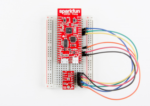
Endless Runner Game

$
0
0

Endless Runner Game a learn.sparkfun.com tutorial

Available online at: http://sfe.io/t716

Introduction

Popularized by mobile games like Temple Run, the endless running type of game is an extremely simplistic spin on the larger “platform” genre where a player has limited control over a character that is constantly moving forward. Flappy bird, while generally not considered a “running” game, was another popular infinite platform game with limited control over the character: users could only tap the screen to make the bird fly upward in order to navigate through obstacles while constantly moving to the right.

We’re going to make our own endless runner game using an Arduino, button and character LCD. While not as visually appealing as Temple Run or Flappy Bird, it’s almost as addicting.

The code for this game comes from Joshua Brooks on Instructables. The original project can be found here.

Playing the endless runner Arduino game

Required Materials

You can complete this project with parts from the SparkFun Inventor’s Kit v4.0. Specifically, you will need:

Note: If you purchase the parts separately, you will need to solder headers onto the LCD.

Suggested Reading

If you aren’t familiar with the following concepts, we recommend checking out these tutorials before continuing:

How to Solder: Through-Hole Soldering

This tutorial covers everything you need to know about through-hole soldering.

What is an Arduino?

What is this 'Arduino' thing anyway?

Installing Arduino IDE

A step-by-step guide to installing and testing the Arduino software on Windows, Mac, and Linux.

SparkFun Inventor's Kit Experiment Guide - v4.0

The SparkFun Inventor's Kit (SIK) Experiment Guide contains all the information needed to build all five projects, encompassing 16 circuits, in the latest version of the kit, v4.0.

Hardware Assembly

Using jumper wires, connect the components as shown in the diagram below.

SIK v4.0 Endless Runner Game

Having a hard time seeing the circuit? Click on the image for a closer look.

Programming

Note: This example assumes you are using the latest version of the Arduino IDE on your desktop. If this is your first time using Arduino, please review our tutorial on installing the Arduino IDE.

Copy and paste the following code in the Arduino IDE. Click Upload to send your compiled code to the Arduino.

language:c
/**
 * Endless Runner
 * Date: August 18, 2017
 * Author: Joshua Brooks (http://www.instructables.com/member/joshua.brooks/)
 * Modified by: Shawn Hymel (SparkFun Electronics)
 *
 * Adjust LCD contrast with the potentiometer. Press the button
 * to start the game. During gameplay, press the button to jump
 * and avoid obstacles. Running into an object will result in
 * restarting. Points are awarded based on distance.
 */

#include <LiquidCrystal.h>

// Constants
#define BTN_PIN 7

#define SPRITE_RUN1 1
#define SPRITE_RUN2 2
#define SPRITE_JUMP 3
#define SPRITE_JUMP_UPPER '.'         // Use the '.' character for the head
#define SPRITE_JUMP_LOWER 4
#define SPRITE_TERRAIN_EMPTY ' '      // User the ' ' character
#define SPRITE_TERRAIN_SOLID 5
#define SPRITE_TERRAIN_SOLID_RIGHT 6
#define SPRITE_TERRAIN_SOLID_LEFT 7

#define HERO_HORIZONTAL_POSITION 1    // Horizontal position of hero on screen

#define TERRAIN_WIDTH 16
#define TERRAIN_EMPTY 0
#define TERRAIN_LOWER_BLOCK 1
#define TERRAIN_UPPER_BLOCK 2

#define HERO_POSITION_OFF 0          // Hero is invisible
#define HERO_POSITION_RUN_LOWER_1 1  // Hero is running on lower row (pose 1)
#define HERO_POSITION_RUN_LOWER_2 2  //                              (pose 2)

#define HERO_POSITION_JUMP_1 3       // Starting a jump
#define HERO_POSITION_JUMP_2 4       // Half-way up
#define HERO_POSITION_JUMP_3 5       // Jump is on upper row
#define HERO_POSITION_JUMP_4 6       // Jump is on upper row
#define HERO_POSITION_JUMP_5 7       // Jump is on upper row
#define HERO_POSITION_JUMP_6 8       // Jump is on upper row
#define HERO_POSITION_JUMP_7 9       // Half-way down
#define HERO_POSITION_JUMP_8 10      // About to land

#define HERO_POSITION_RUN_UPPER_1 11 // Hero is running on upper row (pose 1)
#define HERO_POSITION_RUN_UPPER_2 12

// Globals
LiquidCrystal lcd(13, 12, 11, 10, 9, 8);
static char terrainUpper[TERRAIN_WIDTH + 1];
static char terrainLower[TERRAIN_WIDTH + 1];
static bool buttonPushed = false;

void setup() {
  initializeGraphics();
  lcd.begin(16, 2);
  pinMode(BTN_PIN, INPUT_PULLUP);
}

void loop() {

  static byte heroPos = HERO_POSITION_RUN_LOWER_1;
  static byte newTerrainType = TERRAIN_EMPTY;
  static byte newTerrainDuration = 1;
  static bool playing = false;
  static bool blink = false;
  static unsigned int distance = 0;

  // Check if button is pressed
  if ( digitalRead(BTN_PIN) == LOW ) {
    buttonPushed = true;
  }

  // Show start screen if not currently playing game
  if (!playing) {
    drawHero((blink) ? HERO_POSITION_OFF : heroPos, terrainUpper, terrainLower, distance >> 3);
    if (blink) {
      lcd.setCursor(0, 0);
      lcd.print("Press Start");
    }
    delay(250);
    blink = !blink;
    if (buttonPushed) {
      initializeGraphics();
      heroPos = HERO_POSITION_RUN_LOWER_1;
      playing = true;
      buttonPushed = false;
      distance = 0;
    }
    return;
  }

  // Shift the terrain to the left
  advanceTerrain(terrainLower, newTerrainType == TERRAIN_LOWER_BLOCK ? SPRITE_TERRAIN_SOLID : SPRITE_TERRAIN_EMPTY);
  advanceTerrain(terrainUpper, newTerrainType == TERRAIN_UPPER_BLOCK ? SPRITE_TERRAIN_SOLID : SPRITE_TERRAIN_EMPTY);

  // Make new terrain to enter on the right
  if (--newTerrainDuration == 0) {
    if (newTerrainType == TERRAIN_EMPTY) {
      newTerrainType = (random(3) == 0) ? TERRAIN_UPPER_BLOCK : TERRAIN_LOWER_BLOCK;
      newTerrainDuration = 2 + random(10);
    } else {
      newTerrainType = TERRAIN_EMPTY;
      newTerrainDuration = 10 + random(10);
    }
  }

  // Jump if button is pressed
  if (buttonPushed) {
    if (heroPos <= HERO_POSITION_RUN_LOWER_2) heroPos = HERO_POSITION_JUMP_1;
    buttonPushed = false;
  }

  // Draw hero on screen and check for collisions
  if (drawHero(heroPos, terrainUpper, terrainLower, distance >> 3)) {
    playing = false; // The hero collided with something. Too bad.
  } else {
    if (heroPos == HERO_POSITION_RUN_LOWER_2 || heroPos == HERO_POSITION_JUMP_8) {
      heroPos = HERO_POSITION_RUN_LOWER_1;
    } else if ((heroPos >= HERO_POSITION_JUMP_3 && heroPos <= HERO_POSITION_JUMP_5) && terrainLower[HERO_HORIZONTAL_POSITION] != SPRITE_TERRAIN_EMPTY) {
      heroPos = HERO_POSITION_RUN_UPPER_1;
    } else if (heroPos >= HERO_POSITION_RUN_UPPER_1 && terrainLower[HERO_HORIZONTAL_POSITION] == SPRITE_TERRAIN_EMPTY) {
      heroPos = HERO_POSITION_JUMP_5;
    } else if (heroPos == HERO_POSITION_RUN_UPPER_2) {
      heroPos = HERO_POSITION_RUN_UPPER_1;
    } else {
      ++heroPos;
    }
    ++distance;
  }

  delay(100);
}

// Create custom character LCD graphics
void initializeGraphics() {

  static byte graphics[] = {

    // Run position 1
    B01100,
    B01100,
    B00000,
    B01110,
    B11100,
    B01100,
    B11010,
    B10011,

    // Run position 2
    B01100,
    B01100,
    B00000,
    B01100,
    B01100,
    B01100,
    B01100,
    B01110,

    // Jump
    B01100,
    B01100,
    B00000,
    B11110,
    B01101,
    B11111,
    B10000,
    B00000,

    // Jump lower
    B11110,
    B01101,
    B11111,
    B10000,
    B00000,
    B00000,
    B00000,
    B00000,

    // Ground
    B11111,
    B11111,
    B11111,
    B11111,
    B11111,
    B11111,
    B11111,
    B11111,

    // Ground right
    B00011,
    B00011,
    B00011,
    B00011,
    B00011,
    B00011,
    B00011,
    B00011,

    // Ground left
    B11000,
    B11000,
    B11000,
    B11000,
    B11000,
    B11000,
    B11000,
    B11000,
  };
  int i;

  // Skip using character 0, this allows lcd.print() to be used
  // to quickly draw multiple characters
  for (i = 0; i < 7; ++i) {
    lcd.createChar(i + 1, &graphics[i * 8]);
  }

  // Fill screen with empty terrain
  for (i = 0; i < TERRAIN_WIDTH; ++i) {
    terrainUpper[i] = SPRITE_TERRAIN_EMPTY;
    terrainLower[i] = SPRITE_TERRAIN_EMPTY;
  }
}

// Slide the terrain to the left in half-character increments
void advanceTerrain(char* terrain, byte newTerrain) {
  for (int i = 0; i < TERRAIN_WIDTH; ++i) {
    char current = terrain[i];
    char next = (i == TERRAIN_WIDTH - 1) ? newTerrain : terrain[i + 1];
    switch (current) {
      case SPRITE_TERRAIN_EMPTY:
        terrain[i] = (next == SPRITE_TERRAIN_SOLID) ? SPRITE_TERRAIN_SOLID_RIGHT : SPRITE_TERRAIN_EMPTY;
        break;
      case SPRITE_TERRAIN_SOLID:
        terrain[i] = (next == SPRITE_TERRAIN_EMPTY) ? SPRITE_TERRAIN_SOLID_LEFT : SPRITE_TERRAIN_SOLID;
        break;
      case SPRITE_TERRAIN_SOLID_RIGHT:
        terrain[i] = SPRITE_TERRAIN_SOLID;
        break;
      case SPRITE_TERRAIN_SOLID_LEFT:
        terrain[i] = SPRITE_TERRAIN_EMPTY;
        break;
    }
  }
}

// Draw hero on screen and check for collisions
bool drawHero(byte position, char* terrainUpper, char* terrainLower, unsigned int score) {

  bool collide = false;
  char upperSave = terrainUpper[HERO_HORIZONTAL_POSITION];
  char lowerSave = terrainLower[HERO_HORIZONTAL_POSITION];
  byte upper, lower;

  // Draw the appropriate sprite for the hero (run or jump)
  switch (position) {
    case HERO_POSITION_OFF:
      upper = lower = SPRITE_TERRAIN_EMPTY;
      break;
    case HERO_POSITION_RUN_LOWER_1:
      upper = SPRITE_TERRAIN_EMPTY;
      lower = SPRITE_RUN1;
      break;
    case HERO_POSITION_RUN_LOWER_2:
      upper = SPRITE_TERRAIN_EMPTY;
      lower = SPRITE_RUN2;
      break;
    case HERO_POSITION_JUMP_1:
    case HERO_POSITION_JUMP_8:
      upper = SPRITE_TERRAIN_EMPTY;
      lower = SPRITE_JUMP;
      break;
    case HERO_POSITION_JUMP_2:
    case HERO_POSITION_JUMP_7:
      upper = SPRITE_JUMP_UPPER;
      lower = SPRITE_JUMP_LOWER;
      break;
    case HERO_POSITION_JUMP_3:
    case HERO_POSITION_JUMP_4:
    case HERO_POSITION_JUMP_5:
    case HERO_POSITION_JUMP_6:
      upper = SPRITE_JUMP;
      lower = SPRITE_TERRAIN_EMPTY;
      break;
    case HERO_POSITION_RUN_UPPER_1:
      upper = SPRITE_RUN1;
      lower = SPRITE_TERRAIN_EMPTY;
      break;
    case HERO_POSITION_RUN_UPPER_2:
      upper = SPRITE_RUN2;
      lower = SPRITE_TERRAIN_EMPTY;
      break;
  }

  // Detect collisions with terrain
  if (upper != ' ') {
    terrainUpper[HERO_HORIZONTAL_POSITION] = upper;
    collide = (upperSave == SPRITE_TERRAIN_EMPTY) ? false : true;
  }
  if (lower != ' ') {
    terrainLower[HERO_HORIZONTAL_POSITION] = lower;
    collide |= (lowerSave == SPRITE_TERRAIN_EMPTY) ? false : true;
  }

  // Calculate number of digits needed to draw the score
  byte digits = (score > 9999) ? 5 : (score > 999) ? 4 : (score > 99) ? 3 : (score > 9) ? 2 : 1;

  // Draw the scene
  terrainUpper[TERRAIN_WIDTH] = '\0';
  terrainLower[TERRAIN_WIDTH] = '\0';
  char temp = terrainUpper[16 - digits];
  terrainUpper[16 - digits] = '\0';
  lcd.setCursor(0, 0);
  lcd.print(terrainUpper);
  terrainUpper[16 - digits] = temp;
  lcd.setCursor(0, 1);
  lcd.print(terrainLower);

  // Draw score in upper right of screen
  lcd.setCursor(16 - digits, 0);
  lcd.print(score);

  terrainUpper[HERO_HORIZONTAL_POSITION] = upperSave;
  terrainLower[HERO_HORIZONTAL_POSITION] = lowerSave;

  return collide;
}

What You Should See

When the code finishes uploading, you should be presented with a flashing “Press Start” notification. If you do not see anything on the LCD, try turning the potentiometer to adjust the contrast.

Adjust the contrast with the potentiometer knob

Press the button (the only button available) to begin the game. Once the game starts, you need to press the button again to jump in order to avoid the obstacles that zoom by. If you hit an obstacle, you must start over. The farther you run, the higher your score (as shown by the number in the upper right corner).

Playing the endless runner game

Resources and Going Further

The code and circuit diagram for the Endless Runner Game project can be found on GitHub.

Challenges

  1. Add a difficulty modifier to the game: for every 20 points earned, the terrain moves slightly faster.
  2. Add a second button and remove the “gravity” effect (the part that causes the hero to move back to the first row after jumping). One button causes the hero to move up, and the other causes the hero to move down. This creates more of an “endless flying” game rather than “endless running.” Feel free to change the hero graphic to a plane, spaceship, bird, mosquito, etc.
  3. Use an ultrasonic sensor to control the hero rather than one or more buttons. Set a threshold so that when an object (e.g., a hand) is more than 5 inches from the sensor, the hero is on the top row, and when the object is less than 5 inches from the sensor, the hero is on the bottom row.

Need some inspiration for your next project? Check out some of these related tutorials:

BadgerHack: Gaming Add-On Kit

Make a Breakout clone with the BadgerHack Gaming Add-On Kit.

PiRetrocade Assembly Guide

Build your very own retro gaming controller using the SparkFun PiRetrocade Kit.

Simon Says Assembly Guide

No matter what flavor of the Simon Says Through-hole Soldering Kit you've purchased, this tutorial is here to guide you through the entire build process.

learn.sparkfun.com |CC BY-SA 3.0 | SparkFun Electronics | Niwot, Colorado
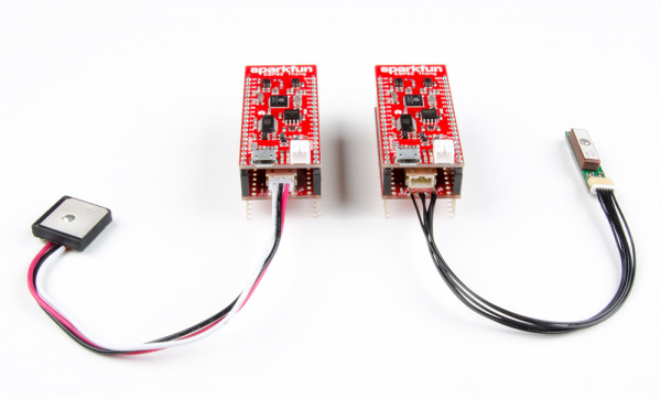
LilyPad Development Board Activity Guide

$
0
0

LilyPad Development Board Activity Guide a learn.sparkfun.com tutorial

Available online at: http://sfe.io/t721

Introduction

Note to Users:

This resource is an adapted version of the LilyPad ProtoSnap Plus Activity Guide for users who want to follow along with the LilyPad Development Board.

The LilyPad ProtoSnap Plus is the latest version of this board.

This guide will get you started with some introductory programming activities exploring each of the LilyPad pieces on the LilyPad Development Board. If you’ve never used Arduino to program before, this guide will walk you through the basics with example code to upload and explore.

You can follow along with this guide with both the LilyPad Development Board, available individually or in a Lab Pack. This guide will not cover construction of a project with conductive thread, so either product will work for you.

LilyPad ProtoSnap Development Board

DEV-11262
$59.95
5
LilyPad Lab Pack

LAB-11762
$600.00

Required Materials

If using the LilyPad Development Board individual kit, you will need to supply your own Mini-B USB cable to upload code. The LilyPad Lab Pack includes cables.

USB Mini-B Cable - 6 Foot

CAB-00598
$1.95

Suggested Reading

What is an Arduino?

What is this 'Arduino' thing anyway?

LilyPad Development Board Hookup Guide

The LilyPad Development Board is a sewable electronics prototyping board that you can use to learn circuits and programming with Arduino, then break apart to make an interactive fabric or wearable project.

Getting Started with LilyPad

An introduction to the LilyPad ecosystem - a set of sewable electronic pieces designed to help you build soft, sewable, interactive e-textile projects.

Before You Begin

Note: This guide assumes you are using the latest version of the Arduino IDE on your desktop. If this is your first time using Arduino, please review our tutorial on installing the Arduino IDE. If you have not previously installed an Arduino library, please check out our installation guide.

Installing Arduino IDE

March 26, 2013

A step-by-step guide to installing and testing the Arduino software on Windows, Mac, and Linux.

Download LilyPad Development Board Example Code

To follow along with the activities in this guide, download the LilyPad Development Board Example Code. Click the following link to download the code:

LilyPad Development Board Example Code

Place the LilyPadDevelopmentBoard_ActivityGuide folder in the Arduino IDE examples directory:

  • Windows: drag the LilyPadDevelopmentBoard_ActivityGuide folder into C:\program files\Arduino-x\examples
  • MacOS: Right-click on the Arduino IDE app and click “Show Package Contents…”. Drag the LilyPadDevelopmentBoard_ActivityGuide folder into Contents/Resources/Java
  • Linux: see http://www.arduino.cc/playground/Learning/Linux

You can also download the code from GitHub.

Install FTDI Drivers

If you’ve never used a LilyPad Arduino before, you will need to install FTDI drivers. Depending on your computer’s operating system, you will need to follow specific instructions. Please go to How to Install FTDI Drivers, for specific instructions on how to install the FTDI drivers onto your computer.


USB Serial Driver Quick Install

August 31, 2017

How to install USB serial drivers on Windows, MacOS , and Linux.

Note that you won’t have to install the FTDI drivers again, but you will need to perform the below three steps every time you want to program the board. These three steps are:

1. Connect the LilyPad Development Board to your computer using the FTDI board and a USB cable.
2. Select "LilyPad Arduino" from Arduino's "Board" menu.
3. Select "ATmega328" from Arduino's "Processor" menu.
4. Select the serial port the LilyPad is connected to from Arduino's "Port" menu.

Let’s go over the three steps in detail:

1. Connect the LilyPad Development Board to Your Computer

Place the LilyPad Development Board on a clean, non-metal work surface. Connect the LilyPad FTDI Board to the headers on the LilyPad Arduino Simple at the center of the Development Board.

FTDI

Connect the other side of the FTDI board to a mini-B USB cable.The cable can only be inserted one way, and should snap in securely.

USB Cable

Then connect the other end of the USB cable to a USB port on your computer.

Computer

Slide the switch on the LilyPad Arduino to the ON position. You will not be able to upload code to the board if it is set to the OFF position.

On Switch

2. Select LilyPad Arduino from the Board Menu

To program the LilyPad Arduino Simple at the center of the LilyPad Development Board, open the Tools>Board list and select LilyPad Arduino. A dot (Windows) or check mark (Mac) will show next to the board in the menu when it is selected, and it will show next to Board in the Tools menu.

Select Board

3. Select ATmega328 from the Processor Menu

After selecting the LilyPad Arduino, there will be two options available in the next menu down labeled Processor. Select ATmega328 for your LilyPad Arduino.

Select Processor

4. Select Port from the Port Menu

Arduino needs to know which port your LilyPad Arduino is attached to so it can program it. Whenever you plug a USB device into your computer, your computer will assign it a port number. Go to the Tools>Port menu, and select the port that has the LilyPad Arduino attached to it.

On Windows ports are listed as COM##; on a Mac or Linux machine they will be “/dev/cu.usbmodem####”. Your screen may look different than the image below, depending on what operating system you are using.

Select COM Port

Troubleshooting: If you don't see a port in the menu, ensure that the board is powered up (switch in the ON position), and that the USB cable is securely connected to both the board and your computer and that you have installed the FTDI drivers. Some USB cables are only meant for charging and don't pass data - they'll power the board, but it won't show up in the port menu. If needed, try a different cable.

Hardware Overview

The LilyPad Development Board features twelve LilyPad components connected to a LilyPad Arduino Simple microcontroller by conductive pathways called traces. Many of these traces are hidden, but for reference, each component on the ProtoSnap has a nearby label with the number of the LilyPad Arduino Simple sew tab it is connected to. For more information on features and technical specs, please refer to the LilyPad Development Board Quickstart Guide.

LilyPad Development Board Labeled

What is a Program?

Programs are sets of instructions that tell a computer to do something, (also called “code” or a “sketch” in Arduino) . This could be blinking LEDs, playing sounds, making decisions based on input from sensors, or a combination of all those things.

When the computer runs a program, it will start at the first instruction, carry it out, and move on to the next one. These instructions come from a specific list of words that the computer knows. If you type in a word that the computer doesn’t know (or more likely, you misspell a word that the computer should know), you’ll get an error when you try to run your program. Don’t feel bad, this happens to everyone and is a normal part of writing programs, and we’ll provide you with some troubleshooting tips as you follow along with the activities in this guide.

In the Arduino system, you’ll write programs on your computer in a free application called the Arduino IDE (“IDE” stands for Integrated Development Environment). This is a specialized text editor with extra buttons to check and send your code to the LilyPad Arduino Simple at the center of your ProtoSnap board. We’ve created a set of of programming examples that you copied to a folder in the Arduino application, we’ll be using them in these activities.

What is a Microcontroller?

The LilyPad Arduino Simple at the center of your ProtoSnap board contains a tiny computer called a microcontroller. It can’t do all the things that a larger computer does, but it’s very good at running programs that control simple hardware like LEDs.

Unlike larger computers, microcontrollers don’t have keyboards and screens for input and output. Most of your input and output will happen through sew tabs; the silver petals with holes in them evenly spaced around the outer edge of all LilyPad boards. Your program can control the sew tabs. It can use them for output by turning them on and off (internally connecting them to voltage or not). It can also use them for input, measuring any voltage coming from other components. It can use this information to read buttons, switches, and various sensors, and use that information to make decisions. (We’ll explore this in future activities.)

If you look closely at the sew tabs, you’ll see that every sew tab has a label next to it. These are the names of the sew tabs, which you’ll need to know to control them from your program. You might have noticed that some of the sew tabs have an “A” as part of the label, and some include a tilde or squiggle “~”. These symbols describe special features that some of the sew tabs have. We’ll tell you about these special features in future activities.

Some of the sew tabs have a “+” or “-” next to them. You can use these sew tabs to provide power and ground to LilyPad boards connected to the LilyPad Arduino Simple.

Sew Tabs and Pins

Every microcontroller chip has electrical connections to the board that look like metal legs. These are commonly referred to as pins. Each sew tab around the outside edge of the LilyPad Arduino Simple is connected electrically to one of these pins on the microcontroller chip. In this guide, we'll be referring to sew tabs when referencing the hardware and electrical connections on your ProtoSnap and pins when talking about the code that controls electricity in or out of the tabs.

In this activity, you’ll run your first program on the LilyPad Arduino Simple at the center of the LilyPad Development Board. It will “just” make an LED blink, but there’s a lot going on even in this simple task. Let’s get started!

LilyPad Boards Used in This Activity

  • LilyPad Arduino Simple
  • LilyPad LED

Parts Used

What is an LED?

“LED” stands for “Light Emitting Diode”. These are electronic components that light up when electricity passes through them. They are available in a variety of colors; your LilyPad Development Board includes five white LEDs and a special tri-color "red-green-blue" (RGB) LED that can display a rainbow of colors.

New Concepts Introduced in This Activity

Exploring Your First Program

We’ve provided a pre-written example program that we’ll load into the Arduino IDE.

Basic Program Structure

We’ll walk you through the example program, explain how it’s constructed, and go over the two basic functions every program needs; setup() and loop().

Lighting Up LEDs

We’ll show you how to light up and blink an LED using the pinMode(), digitalWrite(), and delay() commands.

Modifying Code

A great way to learn to program is to make small changes to a program that someone else has written, and see what happens. We’ll suggest places to try this, and give you a few challenges at the end of each activity.

Example Code

For each of these activities, we’ll start with a pre-written program that you’ll explore and modify. To load the first program, start up the Arduino IDE and go to:

File > Examples > LilyPadDevelopmentBoard_ActivityGuide > LPD_01_Blink

Open Examples folder

Your menu of options may look different depending on what projects you have saved in Arduino. If you downloaded the examples folder from GitHub it may look different, but will have the same content.

If you don't see the examples as shown, check that you have saved the examples folder in the right directory. Refer to the Before You Begin section of this tutorial for more information.

You can also copy and paste the following code into the Arduino IDE (be sure to delete any code already in the window first).

language:c
/*
LilyPad Development Board Activity 1: Blink an LED
SparkFun Electronics
https://www.sparkfun.com/products/11262

Blink the white LED attached to sew tab 5 on the LilyPad Arduino Simple

Follow the tutorial at:
https://learn.sparkfun.com/tutorials/lilypad-development-board-activity-guide/1-blink-an-led

This example is based on: Blink by Scott Fitzgerald
https://www.arduino.cc/en/Tutorial/Blink

This code is released under the MIT License (http://opensource.org/licenses/MIT)

******************************************************************************/

// The setup function runs once when the microcontroller starts up or resets:

void setup()
{
  // Before you use a sew tab (pin), you must set it to be either an input or output:

  pinMode(5, OUTPUT); // Set pin 5 to be an output
}

// After the setup function runs, the loop function runs over and over forever:

void loop()
{
  digitalWrite(5, HIGH); // Give pin 5 a HIGH voltage level (on), which lights up the LED
  delay(1000);           // Pause for 1000 milliseconds (one second), the LED stays on
  digitalWrite(5, LOW);  // Give pin 5 a LOW voltage level (off), which turns off the LED
  delay(1000);           // Pause for 1000 milliseconds (one second), the LED stays off
}

Once you’ve connected your LilyPad Development Board to your computer as shown in the Before You Begin section, and loaded or copied the example program into the Arduino IDE, click the upload button (the round button with the right arrow at the top of the window) and see what happens!

Upload Button

What You Should See

Once the code has uploaded, the first white LED in the bottom row on the Development Board will blink once per second.

Understanding Your Program

In this section, we’ll explain what this program does. For this first activity we’ll be pretty thorough. As we progress through future activities, we’ll just highlight new concepts as we introduce them.

Program Overview

  1. Turn the LED on by sending power to Pin 5.
  2. Wait 1 second.
  3. Turn the LED off by cutting power to Pin 5.
  4. Wait 1 second.
  5. Repeat.

Comments

At the top of the program, you’ll find text describing what the program does, who wrote it, etc. These are called comments. They are there solely for your information and are ignored by the microcontroller. Comments in the Arduino IDE will show up asgray text.

Example Comments

We use special symbols to tell the microcontroller to ignore comments.

  • If you want to write a block of text on multiple lines as we’ve done above, the microcontroller will ignore any text between /* and */.

  • If you want to put a comment on a single line, the microcontroller will ignore any text after two slashes //.

Adding comments to your program is a very good habit to get into! It will help you immensely when you return to your program later and want to understand what you were trying to do. They are also a great tool to add notes for someone who may be using or sharing your code.

Setup() Function

The next section of our program contains a function. A function is a named block of code that does a defined task or set of tasks. When a function is run, all of the code contained between the curly brackets { and } is run. Arduino has two essential functions that are required for every program to run properly: they are setup() and loop(). Arduino programs can use many functions (both built-in and user defined), but they must at least have those two. These and other control structure functions built into the Arduino software will display in green text. Let’s explore the setup function.

Setup

When the microcontroller starts up or is reset, the setup() function runs once. As you may have guessed from the name, the setup() function is typically used to “set up” the hardware so that it operates properly during the rest of the program.

Statements and Commands

Inside functions, we put statements. A statement is a single instruction to the microcontroller. Statements always end with semicolons ;. It’s a common error to forget the semicolon, so if you get an error when uploading your code, double-check that every statement ends with ;.

Most statements will include commands. Commands are specific functions you can use to complete common tasks in Arduino. There are many built-in commands that can be used for all sorts of things - input and output, math, decision making, etc. These commands display in orange text. We’ll cover many useful commands in this guide.

In this program, we’ve put one command in the startup function, called pinMode(). Note the unusual capitalization, called “camel case”. Commands are case-sensitive, so pay special attention to this.

The pinMode() command, as you may have guessed, sets the mode of a pin. Pins are the metal legs on microcontroller chips that are attached to the sew tabs on your LilyPad board. Pins can be configured as inputs or outputs. In this program, we’re going to use pin 5 to control an LED, which is a component sending information (light) to the world, so we’ll make it an OUTPUT.

Commands take various numbers of parameters, which are the information the command needs from you. Parameters go inside parentheses () after a command, and are separated by commas if there are multiple. The pinMode command takes two parameters; the number of the pin, and whether you want it to be an INPUT or an OUTPUT. Here, we’re setting pin 5 to be an OUTPUT.

Reserved Words in Arduino IDE

You may have noticed some parameters are shown inblue text and others plain black. Colored text indicates one of Arduino's reserved words. A reserved word can be a variable, function, or command that has a specified use in the Arduino software. If you are typing something in your code and it displays in colored text, it has a pre-set meaning for Arduino. We'll learn more about variable naming in the next activity. For a full list of reserved words, visit the Arduino Reference website.

Loop() Function

The second essential function needed to run an Arduino program is called loop(). After the setup() function runs once, the loop() function runs over and over, forever (or until you turn off or reset the microcontroller).

A loop() function usually contains the main tasks and behaviors of your program; the things you want it to do repeatedly. You can use this to your advantage; for example, in this program we want to blink an LED continuously. Because the loop() function repeats, we only need to write the code to blink it once, and the loop() function will make it blink over and over.

Loop

The first thing we’ll do is turn our LED on. To do that, we’ll use the digitalWrite() command.

Like pinMode(), digitalWrite() takes two parameters: the pin we want to control, and whether we want to make the pin a HIGH voltage level (on), or a LOW voltage level (off). We want to turn the LED on, so we’ll set pin 5 to HIGH.

Because the microcontroller runs so fast, if we immediately turned the LED off, you’d never notice it. So we’ll slow things down with a command called delay() that does nothing but pause the program for a set amount of time.

The delay() function takes one parameter, the number of milliseconds to wait. There are 1000 milliseconds in one second, so here we’re pausing for one second. If you make this value smaller, the LED will blink faster, and vice-versa. Try it!

After we’ve waited one second, we’ll turn the LED off with a second digitalWrite(), this time setting the pin to LOW to turn the LED off.

Finally, we’ll add a second delay(). This one pauses while the LED is off, finishing the complete on-off “blink” cycle. If we didn’t have the second delay(), the LED would immediately turn on again when loop() starts over. This happens so quickly you wouldn’t notice it being off.

Coding Challenges

  • Try changing the number inside delay() - Can you make the LED blink faster or slower?

  • Changing the pin number inside the digitalWrite() function will change the sew tab being controlled by the code. Can you light up one of the other LilyPad LEDs on the ProtoSnap by changing this number? Hint: don’t forget to set that LED to be an OUTPUT first.

  • Can you modify the code to blink multiple LEDs?

2: Basic Color Mixing

Now that you know how to turn LEDs on and off, let’s try controlling a colorful LED. The LilyPad Development Board has a tri-color, or RGB (Red Green Blue), LED that can be controlled in your code just like the LED from the last activity. Unlike the LED used in the Blink example, this LED is special - it is actually 3 small LEDs in one package - a red, green, and blue. You can access them in code to a variety of color combinations.

LilyPad Boards Used in This Activity

  • LilyPad Arduino Simple
  • LilyPad Tri-Color LED

Parts Used

What is an RGB LED?

Inside an RGB LED are three smaller LEDs - a red, green, and blue. Each of these LEDs is connected to a sew tab on the Tri-Color LED, and they are all connected through a common anode (positive) pin. Unlike other RGB LEDs, this configuration means that to light up the LED you need to ground the individual red, green, and blue LEDs instead of sending them power.

New Concepts Introduced in This Activity

Declaring and Using Variables

A variable is a placeholder for values in your code, typically a descriptive word. While we could continue to write the sew tab or pin number we are referencing in our programs, a variable can make it easier to read, update, and share information within your code. Every time you want to create and use a variable, you must declare it - tell the program what type of data it is storing.

Creating and Naming Variables

Variables can be whatever word or phrase you like, except for specific reserved words within the Arduino IDE that are used for commands, functions, or other specified use. You can learn more about variable types and use on the Arduino Reference site.
Examples:
  • myvariable, MYVARIABLE, myVariable: variables can use a combination of upper case and lower case. It is common to use camel case to make a variable easier to read.
  • my_variable: an underscore is also an option, but no other symbols.
  • myVariable1: you can use numbers within a variable name, but cannot begin with a number
Tips for Naming Your Variables:
  • Use a short, easy to read or type name (up to 63 characters are accepted)
  • Use a meaningful word or phrase for your variables, such as the name of a sensor you are connecting your LilyPad Arduino Simple (or name and number if using more than one of the same type) or type of value it will be used for storing (such as brightness, duration, or ).

Color Mixing

In order to create colors with the RGB LED, you’ll have to set each of the LEDs within it individually. The combination of light from the LEDs mixed together creates new colors.

Example Code

To open the code, go to:

File > Examples > LilyPadDevelopmentBoard_ActivityGuide > LPD_02_BasicColorMixing

You can also copy and paste the following code into the Arduino IDE. Hit upload, and see what happens!

language:c
/*
LilyPad Development Board Activity 2: Basic Color Mixing
SparkFun Electronics
https://www.sparkfun.com/products/11262

Create primary and secondary colors on the tri-color (Red/Green/Blue)
LED connected to sew tabs 9, 11, and 10 on the LilyPad Arduino Simple.

Follow the tutorial at:
https://learn.sparkfun.com/tutorials/lilypad-development-board-activity-guide/2-basic-color-mixing

This code is released under the MIT License (http://opensource.org/licenses/MIT)

******************************************************************************/

// The LilyPad Development Board has a tri-color, also known as an RGB
// (Red / Green / Blue) LED.
// In this activity we'll use digitalWrite to tun the three LEDs on and off
// in various combinations to create eight primary and secondary colors.

// Create integer variables for our LED pins:

// The built-in LED:

int RGB_red = 9;
int RGB_green = 11;
int RGB_blue = 10;


void setup()
{
  // Make all of our LED pins outputs:

  pinMode(RGB_red, OUTPUT);
  pinMode(RGB_green, OUTPUT);
  pinMode(RGB_blue, OUTPUT);

}

void loop()
{

  // This code will step through the six primary and secondary colors, plus white and black.
  // Note: for this particular LED, the wiring shares a common anode (+), which means to
  // turn on the LEDs you will set them LOW instead of HIGH.
  // Keep this in mind as you prototype with the LED and mix your colors.

  // For each of these colors, we'll turn the necessary RGB LEDs on or off.


  // Black (all LEDs off)

  // RGB LEDs:

  digitalWrite(RGB_red, HIGH);
  digitalWrite(RGB_green, HIGH);
  digitalWrite(RGB_blue, HIGH);
  delay(1000);

  // Red (red LED on)

  digitalWrite(RGB_red, LOW);
  digitalWrite(RGB_green, HIGH);
  digitalWrite(RGB_blue, HIGH);
  delay(1000);

  // Yellow (red and green LEDs on)

  digitalWrite(RGB_red, LOW);
  digitalWrite(RGB_green, LOW);
  digitalWrite(RGB_blue, HIGH);
  delay(1000);

  // Green (green LED on)

  digitalWrite(RGB_red, HIGH);
  digitalWrite(RGB_green, LOW);
  digitalWrite(RGB_blue, HIGH);
  delay(1000);

  // Cyan (blue and green LEDs on)

  digitalWrite(RGB_red, HIGH);
  digitalWrite(RGB_green, LOW);
  digitalWrite(RGB_blue, LOW);
  delay(1000);

  // Blue (blue LED on)

  digitalWrite(RGB_red, HIGH);
  digitalWrite(RGB_green, HIGH);
  digitalWrite(RGB_blue, LOW);
  delay(1000);

  // Magenta (red and blue LEDs on)

  digitalWrite(RGB_red, LOW);
  digitalWrite(RGB_green, HIGH);
  digitalWrite(RGB_blue, LOW);
  delay(1000);

  // White (all LEDs on)

  digitalWrite(RGB_red, LOW);
  digitalWrite(RGB_green, LOW);
  digitalWrite(RGB_blue, LOW);
  delay(1000);
}

What You Should See

After uploading your code, the RGB LED will step through a color sequence beginning with all LEDs off (‘black’), red, yellow, green, cyan, blue, magenta, and white. Once the color sequence is complete, the program will loop back to the beginning and repeat the sequence.

Turning on different combinations of three LEDs inside the RGB LED will create new colors. Combining the primary colors of light (red, green, and blue) gives different results than combining pigments in paints or inks. Turning on all three colors will create white - this is called additive color. Take a look a the graphic below to see what colors combine to create primary and secondary colors with light.

Venn Diagram for Additive Colors

Understanding Your Program

Program Overview

  1. Turn all of the LEDs off by turning on all the pins associated with their variables.
    Wait 1 second.
  2. Display red:
    R: ON, G: OFF, B: OFF
    Wait 1 second.
  3. Display yellow:
    R: ON, G: ON, B: OFF
    Wait 1 second.
  4. Display green:
    R: OFF, G: ON, B: OFF
    Wait 1 second.
  5. Display cyan:
    R: OFF, G: ON, B: ON
    Wait 1 second,
  6. Display blue:
    R: OFF, G: OFF, B: ON
    Wait 1 second.
  7. Display magenta:
    R: ON, G: OFF, B: ON
    Wait 1 second.
  8. Display white:
    R: ON, G: ON, B: ON
    Wait 1 second.
  9. Repeat.

Code to Note

The rest of the activities will highlight new programming techniques and concepts as you progress through the guide in a special Code to Note sections. These will showcase specific lines of code and explain them in further detail.
CodeDescription
int RGB_red = 9;
int RGB_green = 11;
int RGB_blue = 10;
Integer Variables:
In this program, we set variables for each of the colored LEDs we are using. Each variable has a descriptive name, which will help us easily keep track of color as we set the individual LEDs in the RGB LED to create color combinations. Notice the int before all the variables used in this program - "int" is short for integer. In addition to deciding the type of data stored in the variable, we can also intialize or preset the information in the variable. In this program, the variables store the number of the sew tab each LED is connected to. We will cover more ways to use variables in later activities, including different variable types. Variables are case sensitive, so make sure you type them identically each time you use in your program.
pinMode(RGB_red, OUTPUT);
pinMode(RGB_green, OUTPUT);
pinMode(RGB_blue, OUTPUT);

Input or Output?:
Each LED you want to control needs to be declared individually as an OUTPUT, even the built-in LEDs within the RGB LED. These use the same format from the Blinking LEDs example, but replacing the sew tab number with the variable names declared at the start of the program.
digitalWrite(RGB_red, LOW);
digitalWrite(RGB_green, HIGH);
digitalWrite(RGB_blue, HIGH);

Creating Colors:
Take a look at the code and notice the RGB LED variables are grouped together. In this code, instead of using digitalWrite() and delay() to create a blink, we are using these commands to step through new colors by turning different combinations of the red, green, and blue channels HIGH and LOW. Examine the code to see how setting these LEDs on or off matches the color chart above.

Note that for the tri-color LED, LOW turns the LEDs on and HIGH turns them off.

Coding Challenges

  • Can you create a new color sequence on the tri-color LED using a new order of colors being displayed?

  • Try changing the delay to create a faster or slower color sequence.

  • Create a variable called delayTime at the top of your code near the other variable declarations. Then replace the 1000 in each delay() function with this variable. This way you can easily set the delay between color steps once at the beginning of your code instead of copying and pasting in each part of the sequence.

3: Custom Color Mixing

In this program, you will continue mixing colors with the tri-color LED, but use a new function to change the brightness of each channel in relation to each other. Adjusting the brightness of the red, green, and blue LEDs within the LED will allow you to create a new range of values and color combinations.

LilyPad Boards Used in This Activity

  • LilyPad Arduino Simple
  • LilyPad Tri-Color LED

Parts Used

New Concepts Introduced in This Activity

Analog Output (Pulse Width Modulation)

Up until this point, you have been controlling LEDs by setting them to one of two states: HIGH (ON) or LOW (OFF). This is great for blinking, but what about adjusting the brightness of your LEDs? This is where analog output comes in handy. Your LilyPad Arduino Simple can mimic a range of brightness on the LEDs by using pulse width modulation. The microcontroller on the LilyPad Arduino Simple can switch voltage to the sew tabs on and off so quickly that it appears to your eyes as if more or less voltage is being provided to an LED. For example, by changing the percent of time that a pin is on, from 0 percent (always off) to 100 percent (always on), you can create the appearance of a range of brightnesses. This percentage is called a duty cycle.

Note: You may have noticed that some of the labels on the illustrations have a special symbol in front of them (~). This indicates that these pins on the LilyPad Arduino Simple are capable of Pulse Width Modulation. However, do not include the "~" symbol in your code. It is only provided to make it easy for you to check which pins can produce PWM (analog) output and is not used in addressing the pins on the LilyPad Arduino Simple in your program. If you try to use analog output commands on a tab without these capabilities, you will see unexpected results these are illustrated in Activity 4: Fading LEDs.

Color Mixing Continued

In the last example, you created basic primary and secondary colors by turning the red, green, and blue channels on or off with different combinations. In this activity, you’ll create tertiary colors by combining the three color channels at 50% brightness levels. There are actually millions of color combinations available using RGB LEDs once you begin experimenting with adjusting the brightness/saturation of each. This example will cover a set of twelve tertiary colors.

Example Code

To open the code, go to:

File > Examples > LilyPadDevelopmentBoard_ActivityGuide > LPD_03_CustomColorMixing

You can also copy and paste the following code into the Arduino IDE. Hit upload, and see what happens!

language:c
/*
LilyPad Development Board Activity 3: Custom Color Mixing
SparkFun Electronics
https://www.sparkfun.com/products/11262

Expand your color options using analogWrite and the RGB (Red Green Blue) LED

Follow the tutorial at:
https://learn.sparkfun.com/tutorials/lilypad-development-board-activity-guide/3-custom-color-mixing

This code is released under the MIT License (http://opensource.org/licenses/MIT)

******************************************************************************/
// The LilyPad Development Board has a RGB (Red / Green / Blue) LED attached to it.
// In this activity we'll use analogWrite to control the brightness of the three LEDs.
// Here we'll create a rainbow of tertiary colors by adding a 50%-brightness option.

// Create integer variables for our LED pins:

// The built-in LED:

int RGB_red = 9;
int RGB_green = 11;
int RGB_blue = 10;


void setup() {

// Make all of our LED pins outputs:

  pinMode(RGB_red, OUTPUT);
  pinMode(RGB_green, OUTPUT);
  pinMode(RGB_blue, OUTPUT);
}

void loop()
{
  // In this code we'll step through twelve rainbow colors (primary, secondary, tertiary).

  // Unlike digitalWrite, which can be only HIGH (on) or LOW (off),
  // analogWrite lets you smoothly change the brightness from 0 (off) to 255 (fully on).
  // When analogWrite is used with the RGB LED, you can create millions of colors!

  // In the analogWrite functions:
  // 0 is off
  // 128 is halfway on (used for the tertiary colors)
  // 255 is full brightness.
  // But because this particular LED is common anode, we will need to reverse these
  // numbers to display correctly:
  // 255 is off
  // 128 remains halfway on
  // 0 is full brightness.

  // Red

  analogWrite(RGB_red,0);
  analogWrite(RGB_green,255);
  analogWrite(RGB_blue,255);
  delay(1000);

  // Orange

  analogWrite(RGB_red,0);
  analogWrite(RGB_green,128);
  analogWrite(RGB_blue,255);
  delay(1000);

  // Yellow

  analogWrite(RGB_red,0);
  analogWrite(RGB_green,0);
  analogWrite(RGB_blue,255);
  delay(1000);

  // Chartruese

  analogWrite(RGB_red,128);
  analogWrite(RGB_green,0);
  analogWrite(RGB_blue,255);
  delay(1000);

  // Green

  analogWrite(RGB_red,255);
  analogWrite(RGB_green,0);
  analogWrite(RGB_blue,255);
  delay(1000);

  // Spring Green

  analogWrite(RGB_red,255);
  analogWrite(RGB_green,0);
  analogWrite(RGB_blue,128);
  delay(1000);

  // Cyan

  analogWrite(RGB_red,255);
  analogWrite(RGB_green,0);
  analogWrite(RGB_blue,0);
  delay(1000);

  // Azure

  analogWrite(RGB_red,255);
  analogWrite(RGB_green,128);
  analogWrite(RGB_blue,0);
  delay(1000);

  // Blue

  analogWrite(RGB_red,255);
  analogWrite(RGB_green,255);
  analogWrite(RGB_blue,0);
  delay(1000);

  // Violet

  analogWrite(RGB_red,128);
  analogWrite(RGB_green,255);
  analogWrite(RGB_blue,0);
  delay(1000);

  // Magenta

  analogWrite(RGB_red,0);
  analogWrite(RGB_green,255);
  analogWrite(RGB_blue,0);
  delay(1000);

  // Rose

  analogWrite(RGB_red,0);
  analogWrite(RGB_green,255);
  analogWrite(RGB_blue,128);
  delay(1000);
}

What You Should See

After uploading your code the RGB LED will step through a rainbow sequence of red, orange, yellow, chartruese, green, spring green, cyan, azure, blue, violet, magenta, and rose, repeatedly.

By adjusting the brightness of each LED in the RGB LED individually, we open up a much wider range of color options to display than the previous activity. In fact, there are many more combinations than we show in the example code. The image below shows a chart of the tertiary colors the example program creates by stepping down the LEDs to half brightness, creating a rainbow with more color transitions than the Basic Color Mixing example. By using analog output to adjust the brightness of each color channel individually, the RGB LED can display almost any color you can choose from a color picker - if you are familiar with RGB sliders in a graphics program, you’ll recognize the 0-255 values used in this code.

Tertiary Colors

Understanding Your Program

Program Overview

  1. Display red:
    R: 100%, G: 0%, B: 0%
    Wait 1 second.
  2. Display orange:
    R: 100%, G: 50%, B: 0%
    Wait 1 second.
  3. Display yellow:
    R: 100%, G: 100%, B: 0%
    Wait 1 second.
  4. Display chartruese:
    R: 50%, G: 100%, B: 0%
    Wait 1 second.
  5. Display green:
    R: 0%, G: 100%, B: 0%
    Wait 1 second.
  6. Display spring green:
    R: 0%, G: 100%, B: 50%
    Wait 1 second.
  7. Display cyan:
    R: 0%, G: 100%, B: 100%
    Wait 1 second.
  8. Display azure:
    R: 0%, G: 50%, B: 100%
    Wait 1 second.
  9. Display blue:
    R: 0%, G: 0%, B: 100%
    Wait 1 second.
  10. Display violet:
    R: 50%, G: 0%, B: 100%
    Wait 1 second.
  11. Display magenta:
    R: 100%, G: 0%, B: 100%
    Wait 1 second.
  12. Display rose:
    R: 100%, G: 0%, B: 50%
    Wait 1 second.
  13. Repeat.

Code to Note

CodeDescription
analogWrite(RGB_red,255);
analogWrite(RGB_green,0);
analogWrite(RGB_blue,0);

Analog Write:
Notice that like digitalWrite(), the analog function takes two pieces of information - the pin it is controlling and a state to set that pin to. The analogWrite() function outputs a voltage between 0 and 3.3V on a pin, with this range divided into 255 steps, where digital output only had HIGH or LOW. This example uses three values to mix the rainbow of tertiary colors: 255 (OFF), 128 (50% brightness), and 0 (100% brightness). You can use any value between 0 and 255 when you begin to experiment with mixing your own colors.

Note that for the tri-color LED, 0 turns the LEDs on and 255 turns them off.

Coding Challenges

  • Try using a color picker to find the R, G, and B values for an interesting color and use that in your program. In order to translate them for use on the tri-color LED, you will need to do some math to reverse them.

  • Try creating your own rainbow light patterns using different values for the color mixes.

4: Fading LEDs

So far in these activities, we’ve controlled the brightness of LEDs manually. In this activity, you’ll start letting the computer do the hard work. By using iteration (counting over a range of numbers), you can fade LEDs smoothly from off to on, a very nice effect you can use in your own projects.

LilyPad Boards Used in This Activity

  • LilyPad Arduino Simple
  • LilyPad LEDs

Parts Used

New Concepts Introduced in This Activity

Iteration Using For-Loops

We’ve already seen that the loop() function repeats forever. But there are many occasions in programming where you’ll want the microcontroller to do something a certain number of times, or count up or down between two numbers. The for() loop is perfect for this.

In this example, we will use the for() loop to slowly increment the brightness of a LED from fully off to fully on, then do the same thing in reverse to turn it off. This creates a “fading” or “breathing” pattern that is great for art projects.

Example Code

To open the code, go to:

File > Examples > LilyPadDevelopmentBoard_ActivityGuide > LPD_04_Fading

You can also copy and paste the following code into the Arduino IDE. Hit upload, and see what happens!

language:c
/*
LilyPad Development Board Activity 4: Fading LEDs
SparkFun Electronics
https://www.sparkfun.com/products/11262

Use for-loops to smoothly vary the brightness of LEDs

Follow the tutorial at:
https://learn.sparkfun.com/tutorials/lilypad-development-board-activity-guide/4-fading-leds

This code is released under the MIT License (http://opensource.org/licenses/MIT)

******************************************************************************/

// In the previous activity we showed you how to manually change the brightness of a LED.
// In this activity we'll show you how to program the computer to do all the work.

// Create integer variables for the LED pins we'll be using:

int LED1 = 6;
int LED2 = A2;

void setup()
{
  // Set the LED pins to be outputs:

  pinMode(LED1, OUTPUT);
  pinMode(LED2, OUTPUT);
}

void loop()
{
  // The two "for loops" below will make a LED fade on and off in a "breathing" pattern.

  // Create a new integer variable called brightness:

  int brightness;

  // Now we'll have the program automatically change the value of brightness
  // using a command called "for".

  // for is like a tiny version of loop. The for command has several parts:
  // 1. something to do before starting (brightness = 0)
  // 2. a test to decide whether to keep going (brightness <= 255)
  // 3. a block of commands to run (everything within the {} below the for)
  // 4. a command to run before doing it again (brightness = brightness + 1)

  // Here's a for command which will start brightness at 0, check to see if it's less than
  // or equal to 255, run the commands after it, then add one to brightness and start over:

  for (brightness = 0; brightness <= 255; brightness = brightness + 1)
  {
    // Within the loop, we'll use brightnes variable to control the brigthness of the LEDs:

    analogWrite(LED1, brightness);
    analogWrite(LED2, brightness);

    // NOTE that not all pins work with analogWrite!
    // The ones with a "~" in front of them will change brightness,
    // the others will only turn on if brightness > 128.
    // Both types are used above, run the code and note the difference between them.

    // The delay command controls the speed - if you make the delay larger,
    // it will slow down the loop. Smaller, and it will run faster:

    delay(5);
  }

  // What if we want the LED to start at full brightness and fade to black?
  // We can easily set up the for loop to run in reverse:

  for (brightness = 255; brightness >= 0; brightness = brightness - 1)
  {
    analogWrite(LED1, brightness);
    analogWrite(LED2, brightness);
    delay(5);
  }
}

What You Should See

Once you upload the program, two of the white LEDs on the ProtoSnap will light up. The LED on 6 will fade smoothly on and off, while the LED on A2 will blink.

If you look at the code, both pins should be fading. This illustrates the difference between the sew tabs which can handle pulse-width modulation, and those that can’t.

Understanding Your Program

Program Overview

  1. Set up the pins we’ll be using
  2. Create a for() loop that makes a variable iterate from 0 to 255
  3. Use that variable to fade the LEDs from off to on
  4. Create a for() loop from makes a variable iterate from 255 to 0
  5. Use that variable to fade the LEDs from on to off
  6. Repeat

Code to Note

Iteration, or making variables change over time, is a very powerful tool in programming. Here we’re using it to smoothly change the brightness of an LED using the analogWrite() command, but you can use it anywhere you want to do something a certain number of times, or you want to change a variable from one value to another in even steps.

Unlike other commands, the for() loop is set up using three statements, which we’ll cover below. You’ll use the same pattern often in your own programming.

CodeDescription
for (brightness = 0;
      brightness <= 255;
      brightness = brightness + 1)

{
analogWrite(LED1, brightness);
analogWrite(LED2, brightness);
delay(5);
}
An Incrementing for() Loop:
Here we're using a for() loop to increment the brightness variable from 0 to 255, running the set of commands within the brackets each time we change it. Let's walk through this code in detail:
for (brightness = 0;
      brightness <= 255;
      brightness = brightness + 1
)
Statements:
The for() loop is set up a bit differently than other commands. It's controlled by three statements in parentheses after the command. Since these are statements and not parameters, they're separated by semicolons.
for (brightness = 0;
      brightness <= 255;
      brightness = brightness + 1)
1. Set Up the Variable:
1. The first statement runs before the counting starts, and is used to set up the variable you'll be counting with. Here we're setting the brightness variable to zero, the number we're starting at.
for (brightness = 0;
      brightness <= 255;
      brightness = brightness + 1)
2. Test Brightness Variable:
The second statement is a test that the for() loop uses to decide whether to keep counting. Here we're checking to see if brightness is less than or equal to 255. If the statement is true, the for loop will keep counting. If it's false, the loop will end.
for (brightness = 0;
      brightness <= 255;
      brightness = brightness + 1)

{
analogWrite(LED1, brightness);
analogWrite(LED2, brightness);
delay(5);
}
If True, Run Code
If the test in the second statement is true, the for() loop will run all of the commands included in the brackets after the for() command. This is where we're setting the brightness of the LED using the brightness variable. Remember to include a delay to slow things down a bit!


We've introduced a small bug into this program: we're using analogWrite for sew tabs A2 and 6, but only sew tab 6 has Pulse-Width Modulation (PWM) capabilities. Notice how A2 is off when the brightness value is below 50%, and on when it's above 50%. If you see your code doing this, now you'll know why.

for (brightness = 0;
      brightness <= 255;
      brightness = brightness + 1)
3. Change Variable
After the commands in the brackets are run, the third statement will change the variable before starting the loop over again. Here we're incrementing the brightness variable by one, but note that you can increment it by any amount, or even a negative value if you wish.
for (brightness = 255;
      brightness >= 0;
      brightness = brightness - 1)

{
analogWrite(LED1, brightness);
analogWrite(LED2, brightness);
delay(5);
}
A Decrementing for() Loop:
Further down in the program, there's a second for() loop that decrements brightness from 255 to 0. Now that you know a little about for() loops, can you spot the differences that make this work?

Coding Challenges

  • Change the delay() values to make the “pulsing” pattern go faster or slower.

  • Try modifying the code to make other LEDs pulse.

  • Can you create a “heartbeat” pattern? (Two on-off pulses then a rest.)

5: Play a Tune

The microcontroller on the LilyPad Arduino Simple can turn its outputs on and off very quickly. If you carefully choose the frequency at which you’re turning an output on and off, and send that signal to the buzzer on the LilyPad Development Board, you can create tones and simple musical tunes.

LilyPad Boards Used in This Activity

  • LilyPad Arduino Simple
  • LilyPad Buzzer

Parts Used

What is a Buzzer?

Inside the LilyPad Buzzer's plastic housing is a coil of wire and a small magnet. When current flows through this coil, it becomes magnetized and pulls towards the magnet, which makes a tiny “click”. When done thousands of times per second, the clicks create tones. In this activity, you’ll pulse the buzzer at specific frequencies to create musical notes. The buzzer can also be used to make alert sounds, robot beeps and boops, etc.

New Concepts Introduced in This Activity

Making Tones

You’ll use the tone() and noTone() commands to drive the buzzer at specific frequencies.

A tone’s pitch is what we perceive when we think of a note as being very high (screams, forks scratching plates, etc.) versus very low (like earth-rumbling bass). The pitch of a tone is very closely related to the frequency played through a speaker. If we toggle a pin from HIGH-to-LOW then LOW-to-HIGH 440 times per second, for example, it produces a 440 Hz (hertz) frequency - a “middle A” pitch. Humans can hear frequencies ranging from 20 (low-pitch, bass) to 20,000 Hz (high-pitch, “ow, my ears”).

Example Code

To open the code, go to:

File > Examples > LilyPadDevelopmentBoard_ActivityGuide > LPD_05_Tune

You can also copy and paste the following code into the Arduino IDE. Hit upload, and see what happens!

language:c
/*
LilyPad Development Board Activity 5: Play a Tune
SparkFun Electronics
https://www.sparkfun.com/products/11262

Play musical notes through the buzzer on the LilyPad Development Board

Follow the tutorial at:
https://learn.sparkfun.com/tutorials/lilypad-development-board-activity-guide/5-play-a-tune

Uses frequencies from "melody" by Tom Igoe: https://www.arduino.cc/en/Tutorial/toneMelody

This code is released under the MIT License: (http://opensource.org/licenses/MIT)

******************************************************************************/

// Create an integer variable naming the pin we'll use for the buzzer.
// On the LilyPad Development Board, it's on 7.

int buzzer = 7;

// Map musical notes to their frequencies by creating variables for them.
// You can find the frequencies for higher and lower notes at:
// https://www.arduino.cc/en/Tutorial/toneMelody

int NOTE_C5 = 523;
int NOTE_CS5 = 554;
int NOTE_D5 = 587;
int NOTE_DS5 = 622;
int NOTE_E5 = 659;
int NOTE_F5 = 698;
int NOTE_FS5 = 740;
int NOTE_G5 = 784;
int NOTE_GS5 = 831;
int NOTE_A5 = 880;
int NOTE_AS5 = 932;
int NOTE_B5 = 988;
int NOTE_C6 = 1047;

// We'll also create a variable for how long to play each note in milliseconds.
// If you make this smaller, the notes will play faster.

int tempo = 500;

void setup()
{
  // Set the buzzer pin to be an output:

  pinMode(buzzer, OUTPUT);
}

void loop()
{
  // This code will play a simple scale from C5 to C6.

  // The tone command takes two parameters: a pin number and a frequency.
  // The tone will play until we stop it with the noTone command.
  // Each of the below blocks plays one note; the note plays during the delay command.

  tone(buzzer,NOTE_C5);
  delay(tempo);

  tone(buzzer,NOTE_D5);
  delay(tempo);

  tone(buzzer,NOTE_E5);
  delay(tempo);

  tone(buzzer,NOTE_F5);
  delay(tempo);

  tone(buzzer,NOTE_G5);
  delay(tempo);

  tone(buzzer,NOTE_A5);
  delay(tempo);

  tone(buzzer,NOTE_B5);
  delay(tempo);

  tone(buzzer,NOTE_C6);
  delay(tempo);

  // A longer delay at the end pauses the sound before looping again.
  // Here we're delaying four times the "tempo" value:

  noTone(buzzer);
  delay(tempo * 4);

  // Try writing your own song using the noted defined at the top of the program!
  // You can change the note duration by multiplying or dividing the "tempo" value
}

What You Should See

Once the code uploads, the buzzer will begin playing a simple musical scale over one octave, pause, and repeat.

Understanding Your Program

Program Overview

  1. Define variables for the audio frequencies we’ll be using, and the tempo (speed at which we’ll be playing).
  2. Configure the sew tab connected to the buzzer to be an output.
  3. Play a series of notes using the tone command.
  4. Pause and repeat.

Code to Note

CodeDescription
int NOTE_C5 = 523;
int NOTE_CS5 = 554;
int NOTE_D5 = 587;
int NOTE_DS5 = 622;
int NOTE_E5 = 659;
int NOTE_F5 = 698;
int NOTE_FS5 = 740;
int NOTE_G5 = 784;
int NOTE_GS5 = 831;
int NOTE_A5 = 880;
int NOTE_AS5 = 932;
int NOTE_B5 = 988;
int NOTE_C6 = 1047;
Frequency and Notes:
To play a specific note you need to know its audio frequency (how fast the output needs to turn on and off). At the top of this program we've included variables for one octave (C5 to C6). These frequencies come from the Tone Melody tutorial on Arduino's site. If you want to play higher or lower notes you can find many more frequencies there.
int tempo = 500;
Setting Tempo:
Another variable we've created is called tempo. We'll use this to control the duration of all the notes, allowing you to change the speed of the tune from one place.
tone(buzzer,NOTE_C5);
Making Tones:
To actually make noise, we use the tone() command. It takes two parameters; the pin which has the buzzer attached to it, and the audio frequency to output.
tone(buzzer,NOTE_B5);
delay(tempo);
Setting Duration:
Once you run the tone() command, the buzzer will keep making sound forever, even while the program continues on to other things. To control the duration of the tone, we'll use delay() along with our tempo variable to pause while the tone is playing.
tone(buzzer,NOTE_B5);
delay(tempo);

tone(buzzer,NOTE_C6);
delay(tempo);

noTone(buzzer);
Changing and Stopping Sounds:
To actually stop the tone, you can run another tone() command with a different note, or use the noTone() command to turn off the sound. The noTone() command only needs one parameter, the pin number it is controlling. We use both methods in this program.
delay(tempo * 4);
Pauses and Tempo:
To pause before the loop() function repeats the scale, we're using another delay() at the end of the program. But to make it pause a bit longer, we multiply our tempo variable by four. This makes it pause for four times as long as each note plays. Half of music is the duration of the notes; you can use multiplication and division to turn individual notes into half notes, quarter notes, create rests, etc. Soon you'll be making real music!

Coding Challenges

  • This program plays a simple scale. Can you change the program to play an actual song?

  • In this program we used a variable called tempo to change the durations of all the notes. In actual music, notes have different durations, and rests (periods of no sound) are important as well. Can you change the durations of individual notes by adding math to the delay values? Hint: If tempo is the duration of a whole note, tempo / 2 would be the duration of a half note, etc.

6: Buttons and Switches

In the activities thus far, you have been using outputs - components that receive a signal or power from the LilyPad Arduino Simple and send information (light and sound) to the world. In the next few activities, we will start to receive input from the world using buttons and sensors to affect the LilyPad boards on the Development Board.

LilyPad Boards Used in This Activity

  • LilyPad Arduino Simple
  • LilyPad Button
  • LilyPad Slide Switch
  • LilyPad LEDs

Parts Used

What is a Switch?

A switch is type of component that controls current flow in a circuit. The LilyPad Slide Switch is an example of a maintained switch, meaning its state remains the same until changed. The board has a small switch labeled ON/OFF; when the toggle is moved to the ON position, the two sew tabs on the switch are connected, allowing current to flow through and close the circuit. When moved to OFF, parts inside the switch move away from each other and open the circuit (disconnecting it).


What is a Button?

The LilyPad Button Board is a special type of switch called a momentary switch - it is only active when an action is applied. When you press the button in the middle of the board, it connects the two sew tabs and allows current to flow through. When you let go of the button, the connection is opened again, and the button springs back into place.

Learn more about how buttons and switches work and the different types you can use in Switch Basics.

New Concepts Introduced in This Activity

Digital Input

Just as digital outputs have two states, ON or OFF (HIGH or LOW in code), digital inputs also have two states. We’ll use a special function called digitalRead() to check if the button has been pressed or if the switch has been flipped when attached to a sew tab on the LilyPad Arduino Simple.

Internal Pull-up Resistors

A pull-up resistor is a small circuit that holds the voltage HIGH (3.3V) on a pin until a button is pressed, pulling the voltage LOW (0V). The most common place you will see a pull-up resistor is when working with buttons. A pull-up resistor keeps the button in one state until it is pressed. The LilyPad Arduino Simple has built-in pull-up resistors, which we will use in code.

Variables for State Change

In Fading LEDs, the for() loop set a variable that was changed during the program. In this activity, you’ll read the state of a button or switch to a variable to hold its state for later use in your program.

If Statements

In the Fading LEDs example, we explored a specialized function, the for() loop. In this activity, we’ll use another function called an If Statement that will check if a state is true or false. Then we will make decisions based on the reading it receives. If/else functions are a way to start adding behavior based on input in your code, whereas the for() loop example created some automation. As you learn more specialized functions in Arduino (or write your own), your programs will become more complex and able to execute more complicated commands and interactions.

Example Code

To open the code, go to:

File > Examples > LilyPadDevelopmentBoard_ActivityGuide > LPD_06_Button

You can also copy and paste the following code into the Arduino IDE. Hit upload, and see what happens!

language:c
/*
LilyPad Development Board Activity 6: Buttons and Switches
SparkFun Electronics
https://www.sparkfun.com/products/11262

Explore digital input and program flow control using the button and switch

Follow the tutorial at:
https://learn.sparkfun.com/tutorials/lilypad-development-board-activity-guide/6-buttons-and-switches

This code is released under the MIT License (http://opensource.org/licenses/MIT)

******************************************************************************/

// Create integer variables for the pins we'll be using

int buttonPin = A5;
int switchPin = 2;

int buttonLED = 5;
int switchLED = 6;

void setup()
{
  // Initialize the button and switch pins as inputs with pullups.
  // Pullups keep the inputs from "floating" when a switch or button is open / unpressed.

  pinMode(buttonPin, INPUT_PULLUP);
  pinMode(switchPin, INPUT_PULLUP);

  // Initialize the LED pins as outputs:

  pinMode(buttonLED, OUTPUT);
  pinMode(switchLED, OUTPUT);
}

void loop()
{
  // This code will read the positions of the button and switch,
  // then use the "if" command to make LEDs follow these states.

  // Create variables to store the button and switch input values:

  int buttonState;
  int switchState;

  // Read and save the states of the button and switch:

  buttonState = digitalRead(buttonPin);
  switchState = digitalRead(switchPin);

  // The if-else statement lets you do different things based on different inputs:

  // The button will read as LOW when it's pressed

  if (buttonState == LOW) // Check to see if buttonState is LOW (pressed)
  {
    digitalWrite(buttonLED,HIGH); // If buttonState is LOW (pressed), turn on the LED
  }
  else
  {
    digitalWrite(buttonLED,LOW); // If buttonState is HIGH (unpressed), turn off the LED
  }

  if (switchState == LOW) // Check to see if switchState is LOW (switch is on)
  {
    digitalWrite(switchLED,HIGH); // If switchState is LOW (on), turn on the LED
  }
  else
  {
    digitalWrite(switchLED,LOW); // If switchState is HIGH (off), turn off the LED
  }
}

What You Should See

When you press the LilyPad Button, the LED connected to pin 5 will turn on. When the button is released, it will turn off. When you slide the LilyPad Slide Switch to the ON position, the LED connected to pin 6 will turn on and remain on until the switch is set to the OFF position.

Understanding Your Program

Program Overview

  1. Check to see if the button is pressed.
    1. If it is, turn buttonLED ON.
    2. If it isn’t, turn buttonLED OFF.
  2. Check to see if the switch is set to ON.
    1. If it is, turn switchLED ON.
    2. If it isn’t, turn switchLED OFF.

Code to Note

CodeDescription
pinMode(buttonpin, INPUT_PULLUP);pinMode(switchpin, INPUT_PULLUP);
Internal Pull-Up Resistor:
In this program, we are setting the sew tab and pin attached to it as an input instead of output. However, with buttons and switches, they can give strange readings when disconnected electrically from a circuit (called 'floating'), so we'll use an internal pull-up resistor built into the LilyPad Arduino Simple, chosen by the INPUT_PULLUP option.
int buttonstate;
int switchstate;
Variables to Store States:
In Fading LEDs, we used a variable that changed over time in the for() Loop, in this program we will use variables to store the state of the button and switch each time the program takes a reading with digitalRead().
buttonstate = digitalRead(buttonpin);
switchstate = digitalRead(switchpin);
Digital Input:
Unlike the analog and digital output functions used in prior activities, the input function digitalRead() only needs one parameter - the pin it is checking. The function checks to see if an input pin is reading HIGH (3.3V) or LOW (0V). It returns a TRUE (1) or FALSE (0) depending on the reading. This code uses the digital read function twice, once to check the state of the button and assign that value to the buttonstate variable and again to check the state of the switch and store that in the switchstate variable.
if(logic statement) {
code to be run if the logic statement is true}
else {
code to be run if the logic statement is false }
If/else Statements:
The if/else statement lets your code react to the world by running one set of code when a logic (conditional) statement in the round brackets is true and another set of code when the statement is false. For example, this example uses two if statements - one checks the button and turns the first LED on when pressed, and the second checks the switch and turns the second LED on when it is set to the ON position.

Read more about if/else statments on Arduino Reference.
buttonstate == LOW
switchstate == LOW
Comparison Operators:
In Arduino, the equals sign (=) is used to assign values. In situations where you want to compare two values, a comparison operator for 'is equal to' == is used.

You can also use:
!= (not equal to)
< (is less than)
> (is greater than)
<= (is less than or equal to)
>= (is greater than or equal to)

Coding Challenges

  • Can you adapt the code so that the opposite actions happen (when the button is pressed it turns the LED off and when the switch is off it sets the LED on)?

  • Try creating a light pattern that displays on the row of LilyPad LEDs when the switch is set to ON.

  • Can you adapt the Play a Tune example to include an on/off switch to control whether the song plays or not?

7: Sensing Light

This activity will also use inputs, this time to sense ambient light in the room and use that reading to light up LEDs. The light sensor is an analog sensor which provides a range of values instead of the digital ON/OFF of the buttons and switches example.

LilyPad Boards Used in This Activity

  • LilyPad Arduino Simple
  • LilyPad Light Sensor
  • LilyPad LEDs

Parts Used

What is a Light Sensor?

The LilyPad Light Sensor outputs voltage between 0V and 3.3V depending on the level of ambient light shining on it. Unlike the other LilyPad components you've used thus far, the light sensor has three sew tabs - positive, negative, and signal (S). The sensor is hooked up to power and ground tabs on the LilyPad Arduino Simple and the S tab is hooked up to a sew tab used for analog input.

As more light is applied on the sensor, more current will be able to flow from the board through the signal tab to your LilyPad Arduino Simple. If the sensor receives no light, no current will flow through it.

New Concepts Introduced in This Activity

Analog Input: Analog to Digital Conversion

In this activity, we’ll explore reading input from a sensor in a new way using analog input. Notice that certain sew tabs on the LilyPad Arduino Simple include an ‘A’ in front of the number - this indicates the pins on the controller and tabs that are connected have an Analog to Digital Converter (ADC). These pins can “sample” an analog signal being read by the controller and translate it to a digital signal that the controller can interpret.

In the last activity, we used digital inputs that read only two states. The LilyPad Light Sensor is an analog sensor, meaning it can read a wide range of values. For analog inputs, the values range from 0 (0V) to 1023 (3.3V).

Serial Monitor and Serial Commands

When using the button and switch, it was pretty easy to tie the ON/OFF to an LED turning ON/OFF. For sensors reading a range of values, it is more useful to actually see those numbers and make decisions using them. The Serial Monitor and Serial Commands are useful tools for displaying information from variables or other debugging tools for your code.

Example Code

To open the code, go to:

File > Examples > LilyPadDevelopmentBoard_ActivityGuide > LPD_07_Light

You can also copy and paste the following code into the Arduino IDE. Hit upload, and see what happens!

language:c
/*
LilyPad Development Board Activity 7: Sensing Light
SparkFun Electronics
https://www.sparkfun.com/products/11262

Explore analog input from the light sensor

Follow the tutorial at:
https://learn.sparkfun.com/tutorials/lilypad-development-board-activity-guide/7-sensing-light

This code is released under the MIT License (http://opensource.org/licenses/MIT)

******************************************************************************/

// Create variables for the pins we'll use:

int sensorPin = A6;

int LED1 = 5;
int LED2 = 6;

void setup()
{
  // Initialize the sensor pin as an input, but without a pullup
  // (Pullups are only used for switch inputs)

  pinMode(sensorPin, INPUT);

  // Initialize the output pins:

  pinMode(LED1, OUTPUT);
  pinMode(LED2, OUTPUT);

  // Initialize the serial monitor:

  Serial.begin(9600);
}

void loop()
{
  int sensorValue;

  // Read the sensor value (will be 0 to 1023):

  sensorValue = analogRead(sensorPin);

  // Print out the sensor reading to the serial monitor:

  Serial.print("sensor value: ");
  Serial.println(sensorValue);

  // Since the sensor value is 0 to 1023,
  // and analogWrite needs a value from 0 to 255,
  // we'll divide the sensor value by four to scale it down:

  analogWrite(LED1,sensorValue / 4);
  analogWrite(LED2,sensorValue / 4);
}

What You Should See

Hold your hand over the light sensor to change the amount of light it is exposed to and observe the LilyPad LEDs. As the light sensor reads less light, the LEDs will reflect the light levels with their brightness levels. You can also use a flashlight to shine more light on the sensor and observe how it affects the LEDs.

Understanding Your Program

Program Overview

  1. Store the light level in the variable sensorValue.
  2. Print the reading to the Serial Monitor.
  3. Set the brightness level of the LEDs to the number stored in the sensorValue variable divided by 4.
  4. Repeat.

Using the Serial Monitor:

The Serial Monitor is one of the Arduino IDE’s many great built-in tools. It can help you understand the values that your program is trying to work with, and it can be a powerful debugging tool when you run into issues where your code is not behaving the way you expected it to. In this activity, you will use the Serial Monitor to print the values from the light sensor to it and observe how they change as the ambient light changes. To see these values, click the Serial Monitor button indicated by the magnifying glass icon in the upper-right corner of the IDE. You can also select Tools > Serial Monitor from the menu.

A new window will pop up where you should then see numeric values appear. Cover the light sensor, and you should see the values change as they scroll by.


The values on your screen may look different than in this image. The range of readings will depend on the light levels in the room you are working in.


If you are having trouble seeing the values, double check that 9600 baud is selected in the dropdown menu at the bottom right of the window and the auto scroll option is checked.

Code to Note

CodeDescription
pinMode(sensorPin, INPUT);
Setting Input:
When using analog sensors, you do not need to use an INPUT similar to what you did in the buttons and switches activity.
Serial.begin(9600);
Serial Begin:
In this program, you will use the Serial Monitor. In order to see anything displayed in the monitor, you must start a serial connection with your LilyPad Arduino Simple by using Serial.begin(). This allows the LilyPad Arduino Simple to send and receive data to your computer. The number 9600 is the communication speed between the devices, called baud rate. The baud rate must match in both your code and the drop down menu in the Serial Monitor.
sensorValue = analogRead(sensorpin);
Analog Input:
Similar to how you checked for a button or switch state in the last activity, the analogRead() function reads the value on a pin attached to an analog sensor. In this code the pin is defined as the sensorPin. Unlike digitalRead(), which returns one of two states (HIGH/LOW), this function returns a number between 0 (0 volts) and 1023 (3.3V volts), which is then assigned to the variable sensorValue.
Serial.print("sensor value: ");
Serial.println(sensorValue);
Serial Print Commands:
After opening the communication to the Serial Monitor in setup, you can now send some values to it. The first line prints some descriptive text to the monitor, and the second prints the value stored in sensorValue. The ln at the end of print tells the monitor to print a new line at the end of each value; otherwise the values would all run together on one line. Try removing the ln to see what happens.

Learn more about the Serial Print commands in the Arduino Reference.
analogWrite(LED1,sensorValue / 4);
analogWrite(LED2,sensorValue / 4);
Adjust Brightness:
These lines of code use the sensorValue variable to set the brightness of the two LEDs. However, remember from the color mixing and fading examples that the analogWrite() can only take a value between 0 and 255, while the sensor will provide values up to four times that number. To get a number the function can use, the program divides the range by 4.

Coding Challenges

  • Can you change the code so that the tri-color LED displays a brighter or dimmer white when the light levels change?

  • Can you change the code so that two colors mix on the tri-color LED when the light levels change?

  • Can you create a blink pattern where the speed of the blink is determined by the light sensor readings?

8: LED Bar Graph

The LilyPad Development Board includes five pre-wired white LEDs, because they’re in a row they’re perfect for creating a LED bar graphs. In this activity, we’ll experiment with graphing the readings from the light sensor onto the row of LEDs.

LilyPad Boards Used in This Activity

  • LilyPad Arduino Simple
  • LilyPad Light Sensor
  • LilyPad LEDs

Parts Used

What is an LED Bar Graph?

An LED bar graph is a row of LEDs that you can use to display information by lighting up one or more of the LEDs. The LilyPad Development Board has a row of LEDs you can use as a bar graph. LED bar graphs have less resolution than other types of displays, but this can be an advantage if you just need a quick indication if a value is high or low.

New Concepts Introduced in This Activity

Using Arrays

Arrays are a handy way to store many variables in one structure. Here we’ll store the pin / sew tab numbers of the white LEDs, making them easier to use as a group.

Creating Custom Functions

So far we’ve been using Arduino’s built-in functions, but you can also create your own. Functions are great for bits of code you want to run repeatedly, or even reuse in other programs.

 Anatomy of a Function

So far we've been using Arduino's built-in functions to do everything, but you can write your own functions as well. Functions are a great way to encapsulate a bit of code that you use a lot, or want to re-use in other programs.

You've already seen the basic structure of the setup() and loop() functions. Your own functions will have the same structure. Let's go over the individual pieces:

Return Type

You've probably noticed the word void at the start of the setup() and loop() functions, and wondered what that means.

Functions can optionally return values, and the return type lets you specify what type of data it will be returning. Some functions, like setup() and loop() just carry out that task. Since they don't return a value, their return type is void.

Other functions, like digitalRead() and analogRead() return a value. These functions have int as their return type.

If you want to write a function that returns a value, specify the return type (usually int) before the name, and include a return statement at the end of the function. Here's an example of a very simple function that always returns 4 when called:

int four()
{
 return 4;
}

Name

Every function needs a name. It should be unique; not the name of an existing function or variable (you can tell this if the name changes color when you type it in). Ideally the name should be descriptive of what the function does, though of course it's your program and you can name things whatever you wish.

Parameters

You've seen that many functions require parameters. For example, pinMode() requires a pin number, and whether that pin should be configured as an INPUT or OUTPUT.

If your custom function needs parameters, you can declare them in the parentheses after the function name. These are declared just like variables in our code; with a type (usually int) and a name. If you need more than one parameter, separate the declarations with commas. Here's an example of a simple function that adds two numbers together and returns the result:

int add(int a, int b)
{
 int c;
 c = a + b;
 return c;
}

Note that when you call a function with parameters, the values are transferred to the function by position, not by name. Let's say you're calling your add functions from the main loop:

var1 = 100;
var2 = 200;
var3 = add(var1,var2);

When your add() function runs, the variable a will get the value 100 from var1, and the variable b will get the value 200 from var2. When the function returns, it will transfer the value from c back to var3 (which will be 300).

Scope

Now's a good time to bring up the concept of scope, which governs where variables are visible in your program (spoiler: it depends on where you declare them.)

In all of our activities, we've declared several variables at the very top of the program. Because they are declared "outside" of setup() and loop(), they've visible within those functions (and any others you create). Because these variables are visible everywhere, they're called global variables.

We can also declare variables inside functions, as we did in the add() function above. This variable will be usable within the function, but if you try to access it elsewhere, you will get an error ("variable not declared in this scope"). These are called local variables.

Both types of variables have their place. Global variables are useful for pin names and option settings, since they're visible everywhere and easy to change from one place. Local variables are ideal for data that doesn't need to leave a function; they allow you to copy and paste functions to new programs.

Learn more about functions and their use at theArduino Reference site.

Incrementing Shortcuts

Many times in programming you’ll want to add or subtract one from a number, such as in a for() loop. In earlier activities, we did this with the pattern x = x + 1. But there are some handy shortcuts you can use:

The Long WayShortcut
x = x + 1 x++
x = x - 1 x--
x = x + 5 x += 5
x = x - 8 x -= 8
x = x * 2 x *= 2
x = x / 4 x /= 4

Learn more about compound operators for shorcuts and their use at the Arduino Reference site.

Example Code

To open the code, go to:

File > Examples > LilyPadDevelopmentBoard_ActivityGuide > LPD_08_BarGraph

You can also copy and paste the following code into the Arduino IDE. Hit upload, and see what happens!

language:c
/*
LilyPad Development Board Activity 8: LED Bar Graph
SparkFun Electronics
https://www.sparkfun.com/products/11262

Play with the row of five LEDs on the bottom of the LilyPad Development Board

Follow the tutorial at:
https://learn.sparkfun.com/tutorials/lilypad-development-board-activity-guide/8-led-bar-graph

This code is released under the MIT License (http://opensource.org/licenses/MIT)

******************************************************************************/

// Create a variable for the light sensor input:

int sensorPin = A6;


// To the five LEDs on the LilyPad Development Board easier to use, we'll put those numbers into an array.
// The initial [5] defines the size of the array (five elements).
// We're filling the array with predefined values, but you could do this
// in your code as well.

int bargraphLED[5] = {5,6,A2,A4,A3};

// The array is indexed from 0 to 4; for example bargraphLED[2] = A2

void setup()
{
  int x;

  // Initialize the sensor pin as an input, but without a pullup
  // (Pullups are only used for switch inputs)

  pinMode(sensorPin, INPUT);

  // Initialize the bargraph LED pins as outputs
  // We'll use the matrix we defined above,
  // where the LEDs are indexed from 0 to 4

  for (x = 0; x <= 4; x++)
  {
    pinMode(bargraphLED[x], OUTPUT);
  }

  // Initialize the serial monitor

  Serial.begin(9600);
}

void loop()
{
  int sensorValue;

  // Read the sensor value (will be 0 to 1023):

  sensorValue = analogRead(sensorPin);

  // Print out the sensor reading:

  Serial.print("sensor value: ");
  Serial.println(sensorValue);

  // Display the sensor reading on the bar graph LEDs.
  // This is a new function that we created ourselves (see below).

  barGraph(sensorValue);
}

// Here we're making our own command called barGraph:
// The first "void" means we don't return anything from this command
// The "int value" is what we'll pass to the command (it must be an integer,
// and it will be called "value" in the command.

void barGraph(int value)
{
  // Create a LED bargraph using value as an input.
  // Value should be in the range 0 to 1023.

  int x;

  // Step through the bargraph LEDs,
  // Turn them on or off depending on value.

  // Value will be in the range 0 to 1023.
  // There are 6 LEDs in the bargraph.
  // 1023 divided by 5 is 204, so 204 will be our threshold
  // between each LED

  for (x=0; x <= 4; x++)
  {
    if (value > (x*204) )
    {
      digitalWrite(bargraphLED[x], HIGH);
    }
    else
    {
      digitalWrite(bargraphLED[x], LOW);
    }
  }
}

What You Should See

After the code loads, the row of white LEDs on the LilyPad Development Board will create a bar graphing showing how much light is hitting the light sensor by lighting up more or less of the row. Try covering the sensor with your hand, or aiming a flashlight at it to see a larger or smaller response from the bar graph.

Understanding Your Program

Program Overview

  1. Set up an array with the white LED pins.
  2. Configure the pins and serial monitor.
  3. Read the light level.
  4. Display it on the bar graph.
  5. Repeat.

Code to Note

CodeDescription
int bargraphLED[5] = {5,6,A2,A4,A3};
Creating an Array:
An array is a convenient way to group a number of variables together. Here we're taking the pin numbers of the white LEDs, and storing them in an array called bargraphLED.

When you declare an array, one method is to specify how many variables (also called elements) it will contain. This array will contain five variables, which we specify in brackets after the variable name.

At the same time that we're declaring the array, we're also filling it in with our LED pin numbers. Later on, if you want to read or write one of those variables, you specify it by position. The positions in this array are numbered 0 through 4. For example, if you want to reference the variable in position 2, you would write bargraphLED[2], which equals A2.
for (x = 0; x <= 4; x++)
{
 pinMode(bargraphLED[x], OUTPUT);
}
Using an Array:
The nice thing about storing our bar graph LEDs in an array is that we can access the pin numbers by their positions (0 to 4). This makes it easy to create for() loops that do the same thing to all of them, like using pinMode() to make them all outputs.
void barGraph(int value)
{
 int x;
 for (x=0; x <= 4; x++)
 {
  if (value > (x*204) )
  {
   digitalWrite(bargraphLED[x], HIGH);
  }
  else
  {
   digitalWrite(bargraphLED[x], LOW);
  }
 }
}
Creating a Custom Function:
In addition to the standard functions setup() and loop(), you can create your own functions. Here we've created a new function called barGraph(). It's set up much like the setup() and loop() functions, but we've added a parameter called value. The value should be from 0 to 1023, the same range we get from analogRead().


Within the brackets of our function, we step through the positions in our LED array (0 to 4). We then determine whether each LED should be lit up or not. Each LED represents about 204 in the range of 0 to 1023, and if value is greater than that number (position * 204), we light it up.

barGraph(sensorValue);
Using a Custom Function:
Now that we've written our custom function, we can use it inside setup() or loop() just like any other command. As you recall, we wrote barGraph() to take one parameter. Here we're providing it with sensorValue. This value will be transferred to the value variable within the function itself.

Coding Challenges

  • Alter the function of the bar graph so that all of the LEDs are on, and go out as the value increases.

  • Alter the value of the bar graph so that it fills in from the right rather than from the left. Hint: Can you do this by declaring the array differently?

9: Theremin Project

Now that you’ve explored the basic programming skills needed to use the Development Board, it’s time to start combining some of those skills into more interactive projects. The first project we’ll explore is creating a musical ‘instrument’ inspired by a theremin. A theremin is an instrument played without needing physical contact, typically utilizing antennas. In this ‘theremin’, you’ll use readings from the light sensor as a controller for frequency of tones produced by the buzzer. We can further categorize this project an opto-theremin because it is using light as a controller. In addition to the sensor and buzzer, we’ll display the light readings on the bar graph and add the button as an on/off trigger.

LilyPad Boards Used in This Activity

  • LilyPad Arduino Simple
  • LilyPad Light Sensor
  • LilyPad Buzzer
  • LilyPad Button
  • LilyPad LEDs

Parts Used

New Concepts Introduced in This Activity

Using the Map() Function

The map() function is a handy function that translates one range of numbers into another range.

For example, let’s say you wanted to use the light sensor (read by analogRead()) to control the brightness of a LED (written by analogWrite()), as we did back in activity 7. But the range of analogRead() (0 to 1023) doesn’t match the range of analogWrite() (0 to 255).

This particular example is easy to solve in that you can simply divide the light sensor value by 4, as we did in activity 7. But it would take a bit more work to solve for arbitrary ranges that may not start at 0, as we’ll be doing in this activity.

The map() function does this for you. The parameters it needs are:

result = map(value,fromLow,fromHigh,toLow,toHigh);

Where fromLow to fromHigh is the range of the original value, and toLow to toHigh is the range we want to translate that value into.

For example, here’s how we’d set up map() for our earlier example:

LEDbrightness = map(lightSensorValue,0,1023,0,255);

It’s worth mentioning that if value isn’t within the original range, map() will still work; but it will return a result outside the target range. If your result must be within the target range, an additional function called constrain() can be used to ensure that:

result = constrain(value,low,high);

If value is already within the range of low to high, the result will be the same as value. But if value is outside that range, it will be set to low or high, whichever is closest. Our complete example would then look like:

LEDbrightness = map(lightSensorValue,0,1023,0,255);
LEDbrightness = constrain(LEDbrightness,0,255);

Example Code

To open the code, go to:

File > Examples > LilyPadDevelopmentBoard_ActivityGuide > LPD_09_Theremin

You can also copy and paste the following code into the Arduino IDE. Hit upload, and see what happens!

language:c
/*
LilyPad Development Board Activity 9: Theremin
SparkFun Electronics
https://www.sparkfun.com/products/11262

A Theremin is an electronic musical instrument that is played by
moving your hands over it. In this activity we'll create a Theremin
using the light sensor and the buzzer.

Follow the tutorial at:
https://learn.sparkfun.com/tutorials/lilypad-development-board-activity-guide/9-theremin-project

This code is released under the MIT License (http://opensource.org/licenses/MIT)

******************************************************************************/

// Create variables for the pins we'll be using

int sensorPin = A6;
int buttonPin = A5;
int buzzer = 7;
int bargraphLED[5] = {5,6,A2,A4,A3};

// Set the highest and lowest frequencies
// (Change these and see what happens)

int highestFrequency = 1047; // C6
int lowestFrequency = 523; // C5

void setup()
{
  int x;

  // Initialize the pins we'll be using

  pinMode(sensorPin, INPUT);
  pinMode(buzzer, OUTPUT);
  pinMode(buttonPin, INPUT_PULLUP);

  for (x = 0; x <= 4; x++)
  {
    pinMode(bargraphLED[x],OUTPUT);
  }

  // Initialize the serial monitor

  Serial.begin(9600);
}

void loop()
{
  int sensorValue;
  int frequency;

  // Read the sensor value (will be 0 to 255):

  sensorValue = analogRead(sensorPin);

  // Print out the sensor reading:

  Serial.print("sensor value: ");
  Serial.println(sensorValue);

  // Display the sensor reading on the bar graph LEDs:

  barGraph(sensorValue);

  // Play a tone based on the light level:

  // The light sensor will return a value from 0 to 1023,
  // but we want to map this to a specific range of frequencies.
  // We'll use a built-in fuction called "map" that transforms one range
  // of values (0 to 1023) to another (lowestFrequency to highestFrequency):

  frequency = map(sensorValue,0,1023,lowestFrequency,highestFrequency);

  if (digitalRead(buttonPin) == LOW) // If the button is pressed:
  {
    tone(buzzer,frequency);
  }
  else
  {
    noTone(buzzer);
  }
}

void barGraph(int value)
{
  // Create a LED bargraph using value as an input.
  // Value should be in the range 0 to 1023.

  int x;

  // Step through the bargraph LEDs,
  // Turn them on or off depending on value.

  // Value will be in the range 0 to 1023.
  // There are 6 LEDs in the bargraph.
  // 1023 divided by 5 is 204, so 204 will be our threshold
  // between each LED (0,42,84, etc.)

  for (x=0; x <= 4; x++)
  {
    if (value > (x*170) )
    {
      digitalWrite(bargraphLED[x], HIGH);
    }
    else
    {
      digitalWrite(bargraphLED[x], LOW);
    }
  }
}

What You Should See

To play the theremin, press and hold the button with one hand and cover the light sensor with the other. As the light sensor reads different light levels, the frequency on the buzzer will change and the row of LEDs will illuminate to show the different tones. Release the button to stop the sounds. You can also use a flashlight to shine more light on the sensor and get a large range of tones.

Understanding Your Program

Program Overview

  1. Create variables to store.
  2. Read the value from the light sensor and store in sensorValue.
  3. Print the light sensor reading to the serial monitor.
  4. Display the sensor reading on the bar graph using a custom barGraph() function.
  5. Map the values from the light sensor to the set range of frequencies (set in lowestFrequency and highestFrequency)
  6. Check to see if the button is pressed.
    1. If it is, send a tone() command to the buzzer using the frequency value.
    2. If it is not, turn the buzzer off using noTone() command.
  7. Repeat.

Code to Note

CodeDescription
map(value,inMin, inMax, outMin, outMax)
Mapping a Range of Values:
The map() function is a tool in Arduino used to take a value from one range and constrain it to another. This is especially helpful when you want to take readings from an analog input (which can range from 0-1023) and use them to display directly on an output (which ranges from 0-255). In previous examples, the code used division to make these two variables compatible. The map function is a little more sophisticated.

The map value has five parameters, listed below:

Value: sensorValue
The values/variable to map. In this code we are using the data we read from the light sensor stored in sensorValue.

inMin: 0
inMax: 1023
The minimum and maximum bounds of the value to be mapped. In this case, since sensorValue is from an analog sensor, these will be 0-1023.

outMin:lowestFrequency
outMax: highestFrequency
The minimum and maximum bounds you want to map the current value to. In this case, we've chosen a range of frequencies stored in the lowestFrequency and highestFrequency variables set at the beginning of the program.

Read more about the map() function on the Arduino Reference site.

Coding Challenges

  • Adjust lowestFrequency and highestFrequency to use different ranges for the tones the theremin creates.

  • Try adding additional sound controls by adding another if/else statement using the switch. Suggestions: Turning a light pattern on/off that coordinates with the sound or switching between different frequency ranges.

10: Twinkling Night-Light Project

In this activity, we’ll pull together elements from earlier activities to create an entire project: a night-light that randomly twinkles LEDs when it gets dark. You could use this as the starting point for a project based around twinkling stars, fireflies, lightning clouds or something else entirely.

LilyPad Boards Used in This Activity

  • LilyPad Arduino Simple
  • LilyPad Tri-Color LED
  • LilyPad Light Sensor
  • LilyPad LEDs

Parts Used

New Concepts Introduced in This Activity

Random

Computers are generally very predictable. Usually this is exactly what we want, but sometimes, especially when creating artistic projects, we want a bit of randomness to make things more surprising and natural. In this activity, we’ll introduce the random() command, which will help you do exactly that.

The random() function is a fun command that will return a random number. You can use it to randomize which LEDs are lit, how long to pause, what tone to play, etc. The random() function takes one parameter, the number of possibilites to choose from. For example, if you wanted to simulate a six-sided die, you would call random(6). The function will then return a number between 0 and 5.

How Random is Random?

The numbers returned by random() aren't entirely random. Every time your program runs, it will repeat the same "random" sequence. This is good enough for many art projects, but if you want a truly random sequence each time your program runs, you can use the randomSeed() command. See Arduino's Reference site for more information on how to use random() in your code.

Setting a Threshold

To determine when it’s dark enough to begin twinkling, we’ll define a threshold value. If the ambient light level is below that value, we’ll begin twinkling. To help you fine-tune this value, we also use the serial monitor to print out the current light level.

Example Code

To open the code, go to:

File > Examples > LilyPadDevelopmentBoard_ActivityGuide > LPD_10_NightLight

You can also copy and paste the following code into the Arduino IDE. Hit upload, and see what happens!

language:c
/*
LilyPad Development Board Activity 10: Twinkling Night-Light
SparkFun Electronics
https://www.sparkfun.com/products/11262

Create a twinkling night-light that turns on when it gets dark.

Follow the tutorial at:
https://learn.sparkfun.com/tutorials/lilypad-development-board-activity-guide/10-twinkling-night-light-project

This code is released under the MIT License (http://opensource.org/licenses/MIT)

******************************************************************************/

// Create variables for the pins we'll be using:

int lightSensor = A6;

// Array of all the LEDs we'll be twinkling. You can set these to the sewtabs
// you'll be using in your project. Remember to only choose outputs that
// have the "~" symbol that are compatible with analogWrite.

int numLEDs = 2;
int LED[2] = {5,6};

int blueLED = 10;

// Threshold for light level (when it's darker than this, twinkle LEDs)

int threshold = 50;

void setup()
{
  int x;

  // Initialize the pins we'll be using

  pinMode(lightSensor, INPUT);

  for (x = 0; x < numLEDs; x++)
  {
    pinMode(LED[x],OUTPUT);
  }

  pinMode(blueLED,OUTPUT);

  // Initialize the serial monitor

  Serial.begin(9600);
}

void loop()
{
  int x,lightLevel,brightness;

  // Read the sensor value (will be 0 to 255):

  lightLevel = analogRead(lightSensor);

  // Print out the sensor reading:

  Serial.print("light level: ");
  Serial.print(lightLevel);
  Serial.print(" threshold: ");
  Serial.print(threshold);
  Serial.print(" twinkle: ");

  // If the light level is below the threshold, twinkle LEDs:

  if (lightLevel < threshold)
  {
    Serial.println("ON");
    digitalWrite(blueLED,LOW); //Note that this is reversed than other LEDS because the tri-color LED is common anode.

    // Pick a random LED:

    x = random(numLEDs);

    // Quickly ramp up the brightness of the LED from off to on:

    for (brightness = 0; brightness <= 255; brightness++)
    {
      analogWrite(LED[x],brightness);
      delay(1);
    }

    // Quickly ramp down the brightness of the LED from on to off:

    for (brightness = 255; brightness >= 0; brightness--)
    {
      analogWrite(LED[x],brightness);
      delay(1);
    }

    // Wait a random amount of time (up to 2 seconds)

    delay(random(2000));
  }
  else
  {
    Serial.println("off");
    digitalWrite(blueLED,HIGH); //Note that this is reversed than other LEDS because the tri-color LED is common anode.
  }
}

What You Should See

Cover the light sensor with your hand. When the sensor’s readings drop below the set threshold, the tri-color LED’s blue LED will light up indicating it is ‘dark’. Then two LEDs along the bottom of the Development Board will twinkle in a random pattern.

Understanding Your Program

Program Overview

  1. Set up our array with the LEDs we want to twinkle.
  2. Set up our input and output pins.
  3. Read the light sensor value; if it’s low, turn on the blue LED and begin twinkling.
  4. To twinkle, choose a random LED from the array, then rapidly brighten and dim it.
  5. Wait a random amount of time between twinkles.
  6. Repeat.

Code to Note

CodeDescription
int x,lightLevel,brightness;
Declaring Multiple Variables Shortcut:
In this program, instead of creating a line for each variable declaration, we combined them into one statement. Since all three of the variables you will use are the same type int, they can be declared together.
int numLEDs = 2;
int LED[2] = {5,6};
Using Arrays:
As in the bar graph activity, we're creating an array called LED with the list of LEDs we'd like to twinkle. Note that these are all PWM-capable pins (the ones with the "~" symbol). Because there could be a few or many LEDs in this list, we're also saving the number of LEDs we'll be using in numLEDs.
int threshold = 50;
Setting a Threshold Variable:
In this program, we'll be creating a night-light that only twinkles when the ambient light level is below a certain threshold. You can fine-tune this value using the information printed in the serial monitor.
lightLevel = analogRead(lightSensor);
...
if (lightLevel < threshold)
{ ...
Check Light Levels Against Threshold:
In the loop()function, the first thing we do is check the ambient light level. If it's below the threshold value, we start twinkling.
x = random(numLEDs);
Choose a Random LED:
First we pick which LED we'd like to twinkle. The random function will choose a number between 0 and numLEDs. We'll use this number as an index into the LED array.
for (brightness = 0; brightness <= 255; brightness++)
{
 analogWrite(LED[x],brightness);
 delay(1);
}


for (brightness = 255; brightness >= 0; brightness--)
{
 analogWrite(LED[x],brightness);
 delay(1);
}

Creating a Twinkle Effect:
To twinkle the LED, we use two for() loops to quickly brighten and dim the LED. Note how we're using the random value x to choose which LED to twinkle.
delay(random(2000));
Adding Random Delays:
Finally, we wait a random amount of time between 0 and 2 seconds (2000 milliseconds). After the time has elapsed, the loop() function automatically starts over, and we'll twinkle again if the light level is still below the threshold.

Coding Challenges

  • Try making the LEDs twinkle faster or slower, or have a shorter or longer pause between twinkles.

  • Instead of twinkling, can you simulate a heartbeat or other pattern?

  • Can you modify the code so that it twinkles when it’s bright out?

  • Can you add sounds to the twinkling?

11: Thermal Alert Project

This activity will use another kind of analog sensor, the temperature sensor. We’ll create a thermal alert program which lights up the channels of the tri-color LED if it senses ‘hot’ or ‘cold’. We’ll also add in the LilyPad Vibe Board to provide some haptic feedback.

LilyPad Boards Used in This Activity

  • LilyPad Arduino Simple
  • LilyPad Temperature Sensor
  • LilyPad Tri-Color LED
  • LilyPad Vibe Board

Parts Used

What is a Temperature Sensor?

The LilyPad Temperature Sensor outputs voltage depending on the ambient temperature around it. Similar to the light sensor, the temperature sensor has three sew tabs - positive, negative, and signal (S). The temperature sensor board will output specific voltage at set temperatures - 10mV for every degree Celsius (C), with 0 degrees C being set at 0.5V. The current flowing from the board through the signal tab to your LilyPad Arduino Simple can be converted through a formula to degrees in Celsius or Fahrenheit.

What is a Vibration Motor?

The LilyPad Vibe Board is a small motor that shakes when current is applied to it. This board can be used in wearable applications to provide simple haptic feedback.

New Concepts Introduced in This Activity

Multiple Thresholds:

In this activity, we’ll use thresholds like the Night-Light project, but assign multiple values associated with hot and cold. We’ll use comparison operators to determine if the temperature is within the bounds of each threshold.

Temperature Conversion

The temperature sensor produces an analog voltage representing the temperature near it. In order to get readings in degrees, we’ll have to do some math. The voltage output from the sensor is linearly proportional to the Celsius temperature. Once you know the output voltage of the sensor, you can calculate the temperature with this equation:


To convert that reading to Fahrenheit, use this formula:


Next we’ll be use Serial Monitor to read the values coming from the sensor and insert the formulas in our code to display the temperature in both Celsius and Fahrenheit.

Example Code

To open the code, go to:

File > Examples > LilyPadDevelopmentBoard_ActivityGuide > LPD_11_ThermalAlert

You can also copy and paste the following code into the Arduino IDE. Hit upload, and see what happens!

language:c
/*
LilyPad Development Board Activity 11: Thermal Alert!
SparkFun Electronics
https://www.sparkfun.com/products/11262

This code reads the input of the temperature sensor and compares it to
a two set thresholds named 'hotAlert' and 'coldAlert'. If temperature is above
the hotAlert threshold, the red channel of the tri-color LED will turn on and the vibe board
will shake. If the temperature falls below the coldAlert threshold, the blue channel of the
tri-color LED will turn on. If the temperature is in the middle of these two thresholds,
the green channel of the tri-color LED will turn on.

Follow the tutorial at:
https://learn.sparkfun.com/tutorials/lilypad-development-board-activity-guide/11-thermal-alert-project

This example is based on Thermal Alert! example in the Digital Sandbox:
https://learn.sparkfun.com/tutorials/digital-sandbox-arduino-companion/12-thermal-alert

This code is released under the MIT License (http://opensource.org/licenses/MIT)

******************************************************************************/

 // Set hot and cold threshold variables to check against. If the temperature reading is above
 // this number in degrees Fahrenheit, we'll turn different LEDs on
 float hotAlert = 80.0;  // 80 degrees Fahrenheit
 float coldAlert = 70.0; // 70 degrees Fahrenheit

// Temperature sensor is connected to A1
 int sensorPin = A1;

// The LEDs in the tri-color LED
int RGB_red = 9;
int RGB_green = 11;
int RGB_blue = 10;

// The vibe board
int motor = 3;

void setup()
{
  // Set the temperature sensor pin as an INPUT:
  pinMode(sensorPin, INPUT);

// Make all of our LED pins outputs:

pinMode(RGB_red, OUTPUT);
pinMode(RGB_green, OUTPUT);
pinMode(RGB_blue, OUTPUT);

pinMode(motor, OUTPUT);

  // Initialize Serial, set the baud rate to 9600 bps.
  Serial.begin(9600);
}

void loop()
{
  // Variable to store raw temperature
  long rawTemp;

  // Variable to store voltage calculation
  float voltage;

  // Variable to store Fahrenheit value
  float fahrenheit;

  // Variable to store Celsius value
  float celsius;

  // Read the raw 0-1023 value of temperature into a variable.
  rawTemp = analogRead(sensorPin);

  // Calculate the voltage, based on that value.
  // Multiply by maximum voltage (4.2V for USB power) and divide by maximum ADC value (1023).
  voltage = rawTemp * (4.2 / 1023.0);
  Serial.print("Voltage: "); // Print voltage reading to serial monitor
  Serial.println(voltage);

  // Calculate the celsius temperature, based on that voltage..
  celsius = (voltage - 0.5) * 100;
  Serial.print("Celsius: "); // Print celcius temp to serial monitor
  Serial.println(celsius);

  // Use a common equation to convert celsius to Fahrenheit. F = C*9/5 + 32.
  fahrenheit = (celsius * 9.0 / 5.0) + 32.0;
  Serial.print("Fahrenheit: "); // Print Fahrenheit temp to serial monitor
  Serial.println(fahrenheit);
  // Print a blank line
  Serial.println();

  // Check the temperature, and turn on the LEDs associated with the hot or cold thresholds
  if (fahrenheit >= hotAlert) // If the temperature rises above the hot threshold:
  {
    digitalWrite(RGB_red, LOW);    // Turn the red LED on
    digitalWrite(RGB_green, HIGH); // Turn the green LED off
    digitalWrite(RGB_blue, HIGH);  // Turn the blue LED off
    digitalWrite(motor, HIGH);     // Turn the motor on to shake as an extra alert
    delay(500);                    // Wait 1/2 second
    digitalWrite(motor, LOW);      // Then turn the motor off
  }
  else if (fahrenheit < coldAlert) // If the temperature falls below the cold threshold:
  {
    digitalWrite(RGB_red, HIGH);   // Turn the red LED off
    digitalWrite(RGB_green, HIGH); // Turn the green LED off
    digitalWrite(RGB_blue, LOW);   // Turn the blue LED on
  }
  else // For all other temperature readings (between hot and cold):
  {
    digitalWrite(RGB_red, HIGH);  // Turn the red LED off
    digitalWrite(RGB_green, LOW); // Turn the green LED on
    digitalWrite(RGB_blue, HIGH); // Turn the blue LED off
  }

  // Wait 1 second between readings
  delay(1000);
}

What You Should See

Open the serial monitor and press your hand on the temperature sensor to see a reading. Your body temperature may not produce a substantial change in the readings from the sensor. Try holding warm or cold objects hear the sensor (be careful with any condensation from a cold object that it does not drip onto the boards). If the reading is above the ‘hot’ threshold, the red LED on the tri-color LED will light up and the vibe motor will briefly shake. If the reading is below the ‘cold’ threshold, the blue LED on the tri-color LED will light up. If the reading is between these two thresholds, the green LED on the tri-color will light up.

If you have a certain temperature range in mind, adjust the threshold variables in your code.

Understanding Your Program

Program Overview

  1. Store the temperature level in the variable rawTemp.
  2. Print the calculated readings to the Serial Monitor.
  3. Turn on the LED color based on the hot and cold thresholds. If the temperature is hot, the vibe motor will turn on for a moment to provide feedback.
  4. Repeat.

Observe Readings in the Serial Monitor:

Open the serial monitor to observe the ambient temperature readings converted from the sensor’s voltage output.

Ways to change the readings: cover the sensor with your hand or breathe on it, move something hot or cold near it.


The values on your screen may look different than in this image. The range of readings will depend on your particular surroundings.


If you are having trouble seeing the values, double check that 9600 baud is selected in the dropdown menu at the bottom right of the window and the auto scroll option is checked.

Code to Note

CodeDescription
float hotAlert = 80.0;
float coldAlert = 70.0;
Set Thresholds:
In this program, two thresholds are set for hot and cold readings. Adjust these as needed for the interaction you would like in your project.
long rawTemp;
float voltage;
float fahrenheit;
float celsius;
Variable Data Types:
Up until this point, most of the variables in the examples have been integers (int). In this program, we'll use a long to store the raw temperature readings and floating point (float), which is a number with a decimal point.

Learn more about floating point numbers on the Arduino Reference site.
rawTemp = analogRead(sensorPin);

voltage = rawTemp * (4.2 / 1023.0);
Serial.print("Voltage: ");
Serial.println(voltage);
Storing Sensor Reading:
First, the program stores the sensor reading into a variable called rawTemp to use in the conversion formulas. Since we know from the sensor's datasheet that voltage being read from the sensor has a relationship to temperature, we can use the voltage = rawTemp * (4.2 / 1023.0) formula to interpret the analog to digital converter's output and determine the voltage.


celsius = (voltage - 0.5) * 100;
Serial.print("Celsius: ");
Serial.println(celsius);

float fahrenheit = (celsius * 9.0 / 5.0) + 32.0;
Serial.print("Fahrenheit: ");
Serial.println(fahrenheit);
Serial.println();
Conversion Formulas:
Next, the code uses the voltage to translate to temperature in Celsius. Then a standard formula for converting Celsius to Fahrenheit (F = C*9/5 + 32). The program also prints all the variables to the serial monitor so you can observe them as they change. This is a great way to see the room's ambient temperature using the development board and adjust the temperature thresholds for your alerts as needed.
if (fahrenheit >= hotAlert)
{

}
else if (fahrenheit < coldAlert)
{

}
else
{

}
Compare Readings to Thresholds:
A set of if statements check if the fahrenheit variable is above, below, or between the hot & cold thresholds. As a result, the LilyPad Arduino Simple turns the red, green, and blue LEDs on depending on which threshold the variable is within. In the first if statement, there is also code to turn on the LilyPad Vibe Board to shake if things are too hot.

Note that the second check uses an else if instead of just an if statement to check the temperature. This is because the temperature sensor cannot be hot and cold at the same time. Using three individual if statements would be inefficient since the Arduino would check each condition. It is not recommended in this case since the sensor will only be able to provide one temperature value at a time. Since all three condition statements cannot be true at the same time, the test is mutually exclusive and requires each test to be grouped together.

Learn more about if/else statements on the Arduino Reference site.

Coding Challenges

  • Can you change the code so that the buzzer sounds different audio alerts depending on the temperature?

  • Can you use the row of white LEDs as a bar graph to get more specific visual indication of the temperature variations?

  • Try creating a ‘quiet’ mode by using the switch to silence the vibe board alarm and just display on the tri-color LED.

Troubleshooting

As you begin to edit the example code and write your own programs, you may experience some error messages. This section highlights a few common issues and solutions as you work on your Arduino code.

At the bottom of the Arduino IDE is section with a black background. This is the Debug Window - if something unexpected or incorrect happens and Arduino can’t communicate to your LilyPad Arduino Simple or run the code you’ve written, an error message will display here. The top of the section will turn orange and a “Copy Error Messages” button will display.

Example Arduino Error

An example of an error displaying in the debug window

Common Error Messages

Error: “Couldn’t find a Board on the selected port”

  • Check that you have the correct port selected.
  • Check that LilyPad Arduino is selected in the board menu, NOT LilyPad Arduino USB.
  • Try pressing the board’s reset button after initiating the upload.
  • Check that the LilyPad Arduino Simple is switched to ON.
  • Check that the USB cable is correctly connected to your computer and LilyPad FTDI board.
  • Check that the FTDI board is correctly connected to the LilyPad Arduino Simple.
  • Check that the USB cable is not a ‘power only’ cable.

Error: “Expected ‘;’ before”

This error happens when there is a missing ; at the end of a statement. Arduino will highlight the line in red in the code window and print a line number in the code around where the error occurred to help you identify where you need to fix something. You can turn on line numbering in Arduino > Preferences.

Semicolon error

In this example, a missing ; after digitalWrite(A5, HIGH) caused the error.

Error: “‘variable’ was not declared in this scope”

Scope errors can happen for a variety of reasons, here are some common things to check:

  • Variable mismatch (spelling, capitalization, spacing differences) when trying to use a variable you have declared in another part of your program
  • Variable was not declared with a type before use.
  • Variable was declared within a function and not globally and is trying to be used outside of that function.

Variable Declaration Error

This error happened because the variable blueLED was mistyped as BlueLED. Arduino did not recognize BlueLED, while it may look similar enough to you, Arduino is case sensitive.

Error: “Expected ‘}’ at end of input”

As you copy and paste to move pieces of your code around or work with nested functions, your code will accumulate a lot of curly brackets. To keep track of nested functions in the example code, we use indented formatting. Each new nested layer of function is indented an addition time to visually organize the code. If one of the opening { or closing } is accidentally deleted or not added, you will get an error.

Closing Brackets Syntax Error

This error happened because the closing bracket for the for() loop is missing. This can be initially misleading, as Arduino highlighted a closing bracket - this one belongs to the loop. The space above it is where Arduino expected a match for the opening bracket of the for() loop - highlighted in blue.

Keeping Track of Brackets

Arduino has a handy feature built in that highlights the matching curly bracket if you place your cursor after one. You can use this to quickly check that there are no brackets left behind.

Bracket Highlighting

Placing the cursor next to the closing bracket of the for () loop highlights its matching opening bracket with a blue outline.

Depending on the Arduino IDE version that you have installed, you may also be able to view the function that was associated with the bracket if it is out of frame. In this example, we were using Arduino IDE v1.8.3.

Bracket Highlighting

Placing the cursor next to the closing bracket of the loop() function highlights the function and bracket when it is out of frame.

Semantics Error and Debugging

Why is my code not working even though it compiles?

This sounds like a pretty general question, but it’s likely a semantic error. While the code is able to compile and is free from syntax errors, the code might not be written to do what you intended. Assuming the hardware connections and boards are good, it is possible that:

  • A pin or variable was not initialized correctly.
  • A variable was not calculated and saved correctly.
  • The wrong variable is printing to the Serial Monitor.
  • You are using values outside of an array[].
  • There is a baud rate mismatch.
  • A delay() function is preventing a certain line from executing fast enough.
  • The sequence of code is not executed properly.

The list of reasons why this may be happening can go on depending on the complexity of the project. The simplest method of debugging can be turning on an LED when we reach a certain part of the code. However, the best method of troubleshooting Arduino code is to try to step through using the serial.print() function to debug. If used correctly, the function is more flexible and can indicate that we have entered a line of code.

Maybe you want to print “I entered this function” to the Serial Monitor after pressing a button or when a sensor reaches a certain value. The serial.print() function can also be used to inspect variables in order to know what to expect from a sensor’s output range. The function can also be used to verify calculations. Other environments allow you to step through the code to simulate what may happen without the need for serial.print().

Learn more SparkFun Troubleshooting Tips

Resources and Going Further

For more information about the LilyPad Development Board, check out the resources below:

Here are some additional LilyPad boards that can be combined with the LilyPad Development Board and project ideas:

LilyPad Pixel Board Hookup Guide

Add changing colors to your wearable projects using LilyPad Pixel Boards.

LilyPad Reed Switch Hookup Guide

A guide to using the LilyPad Reed Switch breakout in your projects.

LilyPad Safety Scarf

This scarf is embedded with a ribbon of LEDs that illuminate when it gets dark out, making yourself more visible to vehicle and other pedestrians.

Here are some resources to help you plan a project with the LilyPad Development Board:

Insulation Techniques for e-Textiles

Learn a few different ways to protect your conductive thread and LilyPad components in your next wearables project.

Planning a Wearable Electronics Project

Tips and tricks for brainstorming and creating a wearables project.

Powering LilyPad LED Projects

Learn how to calculate how many LEDs your LilyPad project can power and how long it will last.

LilyPad Basics: E-Sewing

Learn how to use conductive thread with LilyPad components.

learn.sparkfun.com |CC BY-SA 3.0 | SparkFun Electronics | Niwot, Colorado

Makey Makey Classic Hookup Guide

$
0
0

Makey Makey Classic Hookup Guide a learn.sparkfun.com tutorial

Available online at: http://sfe.io/t727

Introduction

Welcome to the world of Makey Makey! A world where every day objects are much more than what they appear. Bananas are more than just a curvy fruit - they’re keys to a virtual piano. Play-dough isn’t just a tasty child’s toy - it’s the controlling force behind Pacman’s up/down/left/right. And your simple pencil drawings are a portal to Portal.

Makey Makey Classic by JoyLabz

KIT-14478
$49.95

Be prepared to look at every day objects in a whole new light. Be stoked! The world is your construction kit.

Materials Required

  • Makey Makey– The star of the show! The kit should already include:
    • Mini-B USB Cable
    • Alligator Clip Cables
    • Tinned Tipped Wires
  • A computer (Windows, Mac OS X, or Linux) w/ an Available USB Slot
  • Button Material (e.g. fruit, Play-Doh, tin foil, copper tape, pencil, a friend)
  • A Primed Imagination

Suggested Reading

What is a Circuit?

Every electrical project starts with a circuit. Don't know what a circuit is? We're here to help.

Voltage, Current, Resistance, and Ohm's Law

Learn about Ohm's Law, one of the most fundamental equations in all electrical engineering.

What is the Makey Makey?

The Makey Makey is a collaborative project between Jay Silver and Eric Rosenbaum of the MIT Media Lab, and us here at SparkFun Electronics. It’s an invention kit that encourages people to find creative ways to interact with their computers by using every day objects as a replacement for keyboards and mice. With the Makey Makey, you could replace your space key with a banana, use play-doh to move and click your mouse, or high-five your best friend to advance PowerPoint slides.

Hardware Overview

Top Side

The Makey Makey is a two-sided circuit board. On the more simple, top side, the Makey Makey has 6-inputs: the up/down/left/right arrow keys, as well as the space bar and mouse left click:

Makey Makey Top Key Pads Highlighted

Each of those inputs as well as the very important “Earth bar” are available in the form of what I like to call “alligator-bait” connectors. You’ll use the included alligator clip cables to clip right into the hole pairs. This will all be made much more clear in the next section. For now, let’s keep summarizing your Makey Makey.

If any key is activated with the “Earth Bar,” an associated LED will light up next to the pad.

Makey Makey LEDs Highlighted

Back Side

When you flip the board over to the back side, you will notice a mini-B USB connector and POWER LED. The connector is where you will connect the USB cable to a computer. The LED will light up when the board is powered.

Makey Makey USB Connector and Power LED

You've also got access to 12 more keys via the black female headers:

  • W, A, S, D, F, and G on the keyboard side
  • up/down/left/right mouse movement and left/right clicks on the mouse side

The bottom header has six additional ground (aka Earth) outputs.

Makey Makey Keyboard, Mouse, and Ground via Female Header

The top header is an expansion/output header. They KEY OUT and MS OUT are connected to the LEDs on the back to indicate whether you're pressing a keyboard or mouse key, respectively. This can be used to connect low power LEDs and small motors. The RESET will reset the board when connected to ground. There are also pins for power through the 5V and GND. The last two pin (PGD and PGC) are used by the factory to program.

Makey Makey Expansion Header and Status LEDs

The pins broken out through the black female headers are all available in the form of “jumper-wire” connectors to connect male jumper wires, header pins, stripped wires, or tinned tipped wires.

Hardware Hookup

The simplest Makey Makey key you can make is one that only uses your fingers. Below are instructions to make yourself into a key!

Connect a USB Cable

First, grab the mini-B USB cable included with the Makey Makey and insert the cable into the connector. Connect the other end to a USB port of your computer.

Connect the Mini-B USB Cable to the Makey Makey Classic

Ignore Popup Windows

When you first insert the Makey Makey into your computer, a window may pop up. You can cancel or close out the window.

Connect Earth

Touch the Earth bar to ground yourself.

Ground Pad on the Makey Makey

Connect Yourself

Simultaneously touch the SPACE pad. The LED above the SPACE key should light up, and a space command should be sent to your computer.

Pressing a Key on the Makey Makey with Fingers

Now try leaving one finger on the Earth bar while quickly tapping the space button. Getting a feel for it? It should work just like your standard space key!

Testing with a Text Editor

Open up some sort of text editor (Notepad, Word, TextEdit, etc.) on your computer to confirm if the Makey Makey is sending a space to your computer. Remember, just as with your boring ol' keyboard, your computer will interpret keypresses differently depending on what program is active. You can also use your mouse to click between the words in the textbox shown below.

Online Apps for Makey Makey

Looking for some fun games to test out the Makey Makey? Click on the link below to try out the online apps provided by JoyLabz!

Online Apps for Makey Makey

Making Your First Key

Makey Key-Making Materials

To make your “standard” key with the Makey Makey you need the following:

  • A connection to a Makey Makey input. This can be done using alligator clips on the the hole pairs, or jumper wires on the black connector sockets.
  • Connection to a Makey Makey ground (Earth). Again, you’ll connect to earth using either alligator clips or jumper wires.
  • Some sort of key material. This is the fun/creative part! There’s a world of Makey Makey keys out there. Anything that’s even slightly conductive is just waiting to become a computer input. The classics include your fingers, bananas, and pencil scratchings.
  • Something to activate the key, by connecting between the key material and the ground input. Your fingers work pretty well for this. Anything even slightly conductive will do though.

Making a Key

Activating a key means creating a closed circuit. For the circuit to work, electrons have to be able to flow from the Makey Makey input key to Makey Makey’s ground. Usuall your fingers will be the missing link between those two:

Makey Makey key sketch

Image courtesy of JoyLabz

Let’s try making a bona fide Makey Makey key. First, you’ll need to find some sort of key object. Dig around your house, check your fruit basket, your coin purse, or grab a pencil and make a drawing to try it out.

Pick out your favorite-colored alligator clip cable, open one of the jaws, and snap it down onto your key. And clip the other end of the clip into one of the Makey Makey top-side inputs. SPACE is great for testing purposes so we will start with that key pad:

First alligator clip connected to banana

Now, grab a second cable for the ground connection. Black is the classic “ground color”, but set your own trend and pick whatever you want. Clip one end of one cable into the Earth bar, and let the other end dangle for now.

Ground clip attached to banana

Open up some sort of text editor (Notepad, Word, TextEdit, etc.) on your computer. Or you can click between the words in the testbox provided below! Remember, just as with your boring ol' keyboard, your computer will interpret key presses differently depending on what program is active.

Finally! Grab the dangling end of the ground cable with one hand. Make sure you’re touching the metal part of the clip. Then use your other hand to touch the banana, or whatever your key might be. BAM! Space!

Pressing the banana key

Experimenting with Key Materials

Don't have a banana? Try experimenting with different materials. Some materials conduct better than others. Certain materials can also be conductive over a period of time. Try it out!

Below is an example of a hand-drawn key from a standard pencil. A dotted circle was drawn on two sides of a piece of paper and extended to the center. Lines of alternating lengths were drawn (short and long) from each extension with a gap between the lines so that one finger could be used as the key.

hand-drawn Buttons with the Makey Makey

The first drawing with the thin lines labeled “Button 1” was a poor conductor on paper. However, the second drawing with the bold, thick lines labeled “Button 2” was able to conduct. In this case, the pencil was only able to conduct when there was enough of the material. After a few uses, the lines faded and required another layer of graphite.

Pressing Down on the Buttons with the Makey Makey

Using the Back

Remember the black connectors on the other side of the board? There are additional keys that you can connect! You can follow a similar set of steps, replacing alligator cables with jumper wires. The wires included with the Makey Makey is one type of jumper wire. Jumper wires can be a bit tougher to connect to keys. An easy solution is to connect an alligator cable to the free end of the jumper.

Let's try it out. Insert one end of the tinned tipped wire fully into a socket. Connect the other end to a conductive material. You may need to use an alligator cable to extend and connect to the material. Repeat for the ground connection.

The example below is similar to the hand-drawn button. Strips of copper tape were used for “Button 3” instead of a pencil. Since the material is more conductive and thicker than the hand-drawn lines, only two stripes were used. Regular tape was used to secure the tinned ends of the wire against the paper and table. After a few uses, the copper fared better than the graphite pencil.

Copper Tape Button Pad with the Makey Makey

Adding More Keys!

To add more keys, simply connect another alligator clip to another Makey Makey input (e.g. arrow keys or mouse click), and connect the other end to a key material. No further ground connections are necessary as long as there is one available. Be creative and connect as many keys as you can to the Makey Makey!

Jim and Various Keys for the Makey Makey

Jim and a Makey Makey connected to various types of keys!

What Makes a Key? Conductivity.

A material is a conductor if it allows electricity (even just a tiny bit of it) to flow. This is the magic behind the Makey Makey: most of the world is conductive! Anything metal will almost certainly conduct electricity. The “standard” conductors are copper, silver, gold, etc. But with the Makey Makey our conductor scope grows. Most organic materials - things like human skin, liquids, foods, and frog legs - are at least a little conductive. And that’s really all the Makey Makey needs.

If an object isn’t conductive, it’s an insulator. Common insulators include plastic, glass, ceramic and wood. You can usually tell just by looking at something whether it’s an insulator or conductor. You’ll have to watch out for objects like this, as they just won’t work with the Makey Makey. To get around that, though, you can line them with a conductive material (like copper tape, or just regular old wire), draw, or paint. This creates the illusion that they’re conducting electricity.

Makey Makey Controller with Copper Tape

Makey Makey held against an enclosure and connected to a controller with copper tape and alligator cables.

Resistance is a measure of exactly how conductive a device is. Resistance can be measured with just about any standard multimeter. Any object with a resistance of about 4.5MΩ (that’s a really high resistance) or less should work as a Makey Makey input. If you’re not sure if something will work with the Makey Makey, whip out a multimeter (buy one if you have to, they’re an essential tool for electronics hobbyists) and test that resistance! Or, better yet, just connect it to your Makey Makey and experiment.

Remapping Keys

The Makey Makey v1.2 Classic has an option to change the keys if you ever need to change the default keys. To remap the key, you will need to go online and head over to JoyLabz using any internet browser. Click on the button below to open a new window.

Remap Your Makey Makey Key!

Following the instructions provided by JoyLabz is pretty straightforward but we also outlined the instructions below if you need. By clicking on the link, it should have opened up a new tab or window. You will have two options. Click on the Makey Makey Classic.

Makey Makey Remapping Keys: Selecting the Makey Makey Classic

Once selected, the prompt will ask you to check and ensure that you have the correct Makey Makey version. On the back side with the black female headers, you will notice that the board has a version number printed as v.1.2 If you do not have that version, you will not be able to remap the keys with these instructions. If it is v.1.2, proceed by connecting the mini-b USB cable to the Makey Makey and clicking on the START button. For now, do not connect the other end to your computer's USB port.

Makey Makey Remapping Keys: Check Your Version

Grab two alligator clips and connect the up (↑) and down (↓) arrows together. Then connect the left (←) and right (→) arrows. Once connected, connect the other end of the USB cable to your computer's USB port. You will notice the green LEDs begin to fade in and out indicating that the Makey Makey is in programming mode.

Makey Makey Remapping Keys: Adding Alligator Clips to Cursors

The browser will eventually respond with a note indicating that the Makey Makey is detected. If the you do not see the message, you may need to unplug the USB cable from your computer and start again. Also, make sure that the browser to remap keys is active. Otherwise, follow the prompt by removing the alligator clips if the Makey Makey is in programming mode.

Makey Makey Remapping Keys: Removing Alligator Clips

With one hand, ground yourself by touching the exposed GND pads. With the other hand, touch the left or right keys to navigate to the key that you are interested in remapping.

Makey Makey Remapping Keys: Remap  Key

The key that will be remapped will be highlighted in yellow. Let's remap the left mouse “CLICK” on the Makey Makey. Navigate to the left mouse “CLICK” button. Once selected, keep one hand on GND and touch the “CLICK” pad to remap the key.

Makey Makey Remapping Keys: Navigate to Key

The key that is being remapped will be highlighted green. The replacement key will be highlighted in yellow. At this point, you can select the replacement key located at the bottom of the browser. Navigate through the keys using the Makey Makey's arrow pads. Let's select the “enter” key by moving to its icon and touching the “CLICK” pad.

Makey Makey Remapping Keys: Select Replacement Key

The browser will have a nice animation and replace the old key with a new key. At this point, you can continue to remap the other keys. For now, we will just remap one key.

Makey Makey Remapping Keys: Replaced Key

Navigate to the SAVE button by pressing on the down pad. Here, you will be able to SAVE the remapped key, CANCEL any changes that you have made, or RESTORE the Makey Makey default keys. Let's save the remapped key by pressing on the “CLICK” pad.

Makey Makey Remapping Keys: Save

A prompt will pop up asking you to confirm the save. Use the left arrow pad to highlight “YES”. Click on the “CLICK” pad to confirm.

The settings will save and you will be greeted with a “SUCCESS!”.

Makey Makey Remapping Keys: Success

Troubleshooting

Not working as expected? Check out the troubleshooting section for the Makey Makey v.1.2 Classic:

JoyLabz Troubleshooting for the Makey Makey Classic

You may even want to check out their Frequently Asked Questions:

JoyLabz FAQ for the Makey Makey

Resources and Going Further

If you’re left with any questions after reading this tutorial, here are all the Makey Makey-related resources we can find:

Example Projects

Sometimes following by example is the best way to learn. If you’re not sure where to start with the Makey Makey, give these examples a look-over. I hope they inspire you! If you want your project added to this list, post it in the comments below, or send us an email!


learn.sparkfun.com |CC BY-SA 3.0 | SparkFun Electronics | Niwot, Colorado

Qwiic Human Presence Sensor (AK9753) Hookup Guide

$
0
0

Qwiic Human Presence Sensor (AK9753) Hookup Guide a learn.sparkfun.com tutorial

Available online at: http://sfe.io/t699

Introduction

The AK9753 Human Presence sensor is a Qwiic enabled, 4-channel Nondispersive Infrared Sensor (NDIR). Each channel has a different field of view, so not only can the AK9753 detect a human, but it can also tell which direction the person is moving.

SparkFun Human Presence Sensor Breakout - AK9753 (Qwiic)

SEN-14349
$24.95

This hookup guide will show you how to get started taking basic reading from the sensor. We will cover both a serial output of readings as well as nice graph of the derivative of our readings from a single channel.

Required Materials

To get started, you’ll need a microcontroller to, well, control everything.

SparkFun RedBoard - Programmed with Arduino

DEV-13975
$19.95
18
SparkFun ESP32 Thing

DEV-13907
$19.95
52
Raspberry Pi 3

DEV-13825
$39.95
85
Particle Photon (Headers)

WRL-13774
$19.00
27

Now to get into the Qwiic ecosystem, the key will be one of the following Qwiic shields to match your preference of microcontroller:

SparkFun Qwiic HAT for Raspberry Pi

DEV-14459
$4.95
SparkFun Qwiic Shield for Arduino

DEV-14352
$5.95
Qwiic Shield for Photon

SPX-14202
$1.00

You will also need a Qwiic cable to connect the shield to your human presence sensor, choose a length that suits your needs.

Qwiic Cable - 500mm

PRT-14429
$1.95
Qwiic Cable - 100mm

PRT-14427
$1.50
Qwiic Cable - 200mm

PRT-14428
$1.50
Qwiic Cable - 50mm

PRT-14426
$0.95

Suggested Reading

If you aren’t familiar with our new Qwiic system, we recommend reading here for an overview. We would also recommend taking a look at the following tutorials if you aren’t familiar with them.

I2C

An introduction to I2C, one of the main embedded communications protocols in use today.

Qwiic Shield for Arduino & Photon Hookup Guide

Get started with our Qwiic ecosystem with the Qwiic shield for Arduino or Photon.

Hardware Overview

Listed below are some of the characteristics and operating ranges of the AK9753 Human Presence Sensor.

CharacteristicRange
Operating Voltage3.3V
Operating Temperature-30°C to 85°C
Current Consumption10 μA (typ.), 100 μA (max) (5V)
Spectral Sensitivity5-7 μm (5V)
Detection Range3 m (5V)
Temperature Sensor Range-10° to 60°C

Pins

PinDescriptionDirection
GNDGroundIn
3.3VPowerIn
SDADataIn
SCLClockIn
INTInterrupt, goes high when data is ready. After data is read, the pin pulls lowOut

Optional Features

There are several jumpers on board that can be changed to facilitate several different functions. The first of which is the I2C pull-up jumper, highlighted below. If you have your own I2C pull ups, you can remove the solder from this jumper.

Top View of Board

The JP8 jumper on the back of the board (highlighted below) can be sliced with a hobby knife to disable the interrupt capability. The “Field of View” text and box shows the field of view of each of the 4 sensors. From the sensor’s point of view, channel 1 is on top, 2 is on left, 3 is on bottom, and 4 is on the right.

Bottom of Board

Addresses 0 and 1 can be used to change the I2C address of the board in case you have multiple devices using the same address. The below table shows the addresses that correspond to the different combinations of opened and closed jumpers.

Top View with Jumpers for Address

Address 0Address 1I2C Address
000x64
010x65
100x67
11Switch Mode

Switch mode is available if you want to avoid using I2C altogether. In switch mode, data is written to the interrupt pin. The pin pulls high when the difference between two outputs (ex. IR1-IR3 or IR2-IR4) is greater than the upper or lower thresholds set in EEPROM by the manufacturer. This mode is a good solution if your project doesn’t need much accuracy.

Hardware Assembly

If you haven’t yet assembled your Qwiic Shield, now would be the time to head over to that tutorial. With the shield assembled, Sparkfun’s new Qwiic environment means that connecting the sensor could not be easier. Just plug one end of the Qwiic cable into the AK9753 Human Presence Sensor, the other into the Qwiic Shield and you’ll be ready to upload a sketch and start sensing humans. It seems too easy, but thats why we made it this way!

Software

Note: This example assumes you are using the latest version of the Arduino IDE on your desktop. If this is your first time using Arduino, please review our tutorial on installing the Arduino IDE. If you have not previously installed an Arduino library, please check out our installation guide.

First, you’ll need to download and install the SparkFun AK975X Arduino library, this can be done using the button below or by using the Arduino Library Manager.

Download the SparkFun AK975X Arduino Library

Before we get started developing a sketch, let’s look at the available functions of the library.

  • int16_t getIR1();— Returns the value from channel 1, there are also functions getIR2(); and so on and so forth.
  • void refresh();— Reads the dummy register telling the sensor to calculate the next reading.
  • boolean available();— Returns true if data is ready.
  • boolean overrun();— Returns true if the overrun bit is set.
  • void softReset();— Resets the IC via software.
  • void setMode(uint8_t mode = AK975X_MODE_0);— Set mode of the sensor. Mode 0 is continuous read mode.
  • void setCutoffFrequency(uint8_t frequency = AK975X_FREQ_8_8HZ);— Sets the filtering frequency. 8Hz is the fastest and least filtered.
  • float getTemperature();— Returns sensor temperature in °C.
  • float getTemperatureF();— Returns sensor temperature in °F.
  • void enableDebugging(Stream &debugPort = Serial);— Self explanatory, allows the output various extra messages to help with debugging.
  • void disableDebugging();— Disables debugging messages.
  • uint8_t readRegister(uint8_t location);— Basic read of I2C register.
  • void writeRegister(uint8_t location, uint8_t val);— Writes to an I2C register.
  • uint16_t readRegister16(byte location);— Reads a 16-bit value from an I2C register.

Example 1: Basic Serial Readings

The example code shown below will get you started taking basic serial readings from the Human Presence Sensor. This sketch is relatively simple, pulling values using the getIRX(); functions and printing them over a serial terminal at 9600 baud.

language:c
#include <Wire.h>

#include "SparkFun_AK975X_Arduino_Library.h" //Use Library Manager or download here: https://github.com/sparkfun/SparkFun_AK975X_Arduino_Library

AK975X movementSensor; //Hook object to the library

int ir1, ir2, ir3, ir4, temperature;

void setup()
{
  Serial.begin(9600);
  Serial.println("AK975X Read Example");

  Wire.begin();

  //Turn on sensor
  if (movementSensor.begin() == false)
  {
    Serial.println("Device not found. Check wiring.");
    while (1);
  }
}

void loop()
{
  if (movementSensor.available())
  {
    ir1 = movementSensor.getIR1();
    ir2 = movementSensor.getIR2();
    ir3 = movementSensor.getIR3();
    ir4 = movementSensor.getIR4();
    float tempF = movementSensor.getTemperatureF();

    movementSensor.refresh(); //Read dummy register after new data is read

    //Note: The observable area is shown in the silkscreen.
    //If sensor 2 increases first, the human is on the left
    Serial.print("1:DWN[");
    Serial.print(ir1);
    Serial.print("]\t2:LFT[");
    Serial.print(ir2);
    Serial.print("]\t3:UP[");
    Serial.print(ir3);
    Serial.print("]\t4:RGH[");
    Serial.print(ir4);
    Serial.print("]\ttempF[");
    Serial.print(tempF);
    Serial.print("]\tmillis[");
    Serial.print(millis());
    Serial.print("]");
    Serial.println();
  }
  delay(1);
}

The output should look similar to the image below, with the values of each channel, temperature, and timestamp of the reading in each row.

Serial Output

Click the image for a closer look.

Example 2: Graphing the Human Presence Sensor Serial Data

The next example takes the derivative of a single channel and displays this on the serial plotter. The code for this example is shown below. Notice how you can change the sensitivity of the Human Presence Sensor using the sensitivity value. It is set at 50 by default, and values lower than this will yield higher sensitivity.

language:c
#include <Wire.h>

#include "SparkFun_AK975X_Arduino_Library.h" //Use Library Manager or download here: https://github.com/sparkfun/SparkFun_AK975X_Arduino_Library

AK975X movementSensor; //Hook object to the library

unsigned int upValue; // current proximity reading
unsigned int averageValue;   // low-pass filtered proximity reading
signed int fa2;              // FA-II value;
signed int fa2Derivative;     // Derivative of the FA-II value;
signed int fa2DerivativeLast;     // Last value of the derivative (for zero-crossing detection)
signed int sensitivity = 50;  // Sensitivity of touch/release detection, values closer to zero increase sensitivity

#define LOOP_TIME 30  // Loop duration in ms. 30ms works well.

//Exponential average weight parameter / cut-off frequency for high-pass filter
//#define EA 0.3  //Very steep
//#define EA 0.1  //Less steep
#define EA 0.05  //Less steep

void setup()
{
  Serial.begin(9600);

  Wire.begin();

  //Turn on sensor
  if (movementSensor.begin() == false)
  {
    Serial.println("Device not found. Check wiring.");
    while (1);
  }

  upValue = movementSensor.getIR3(); //Get one of the latest IR values
  averageValue = upValue;
  fa2 = 0;
  movementSensor.refresh(); //Read dummy register after new data is read
}

void loop()
{
  unsigned long startTime = millis();

  while (movementSensor.available() == false) delay(1); //Wait for new data

  upValue = movementSensor.getIR3(); //Get one of the latest IR values
  movementSensor.refresh(); //Read dummy register after new data is read

  fa2DerivativeLast = fa2Derivative;
  fa2Derivative = (signed int) averageValue - upValue - fa2;
  fa2 = (signed int) averageValue - upValue;

  //Turn on various variables to see how they respond on the graph
  //Serial.print(upValue);
  //Serial.print(",");
  //Serial.print(fa2);
  //Serial.print(",");
  Serial.print(fa2Derivative);
  Serial.print(",");

  //Look to see if the previous fa2Der was below threshold AND current fa2Der is above threshold
  //Basically, if the sign of the fa2Ders has switched since last reading then we have an event
  if ((fa2DerivativeLast < -sensitivity && fa2Derivative > sensitivity) || (fa2DerivativeLast > sensitivity && fa2Derivative < -sensitivity)) // zero crossing detected
  {
    if (fa2 < -sensitivity) // minimum
    {
      Serial.print(-1000); //Cause red line to indicate entering presence
      Serial.print(",");
      //Serial.print("Entered view");
    }
    else if (fa2 > sensitivity) // maximum
    {
      Serial.print(1000); //Cause red line to indicate exiting presence
      Serial.print(",");
      //Serial.print("Exited view");
    }
    else
    {
      Serial.print(0); //Cause red line to indicate no movement
      Serial.print(",");
      //Serial.print("No Movement");
    }
  }
  else
  {
    Serial.print(0);
    Serial.print(",");
  }

  Serial.println();

  // Do this last
  averageValue = EA * upValue + (1 - EA) * averageValue;
  while (millis() < startTime + LOOP_TIME); // enforce constant loop time
}

Once again, the output for this example code should look something like the below image. This graph is the derivative of a single channel on our presence sensor, so any variance from 0 shows the rate of change of the signal.

Serial Plotter

Click the image for a closer look.

Resources and Going Further

Now that you’ve successfully got your AK9753 up and running, it’s time to incorporate it into your own project!

For more information on the AK9753, check out the resources below:

Need some inspiration for your next project? Check out some of these related tutorials:

RedBoard Santa Trap

A fun holiday project to try for anyone looking to catch Santa on Christmas!

PIR Motion Sensor Hookup Guide

An overview of passive infrared (PIR) motion detecting sensors, and how to hook them up to an Arduino.

ZX Distance and Gesture Sensor SMD Hookup Guide

How to connect and use the SparkFun ZX Distance and Gesture Sensor with an Arduino.

OpenPIR Hookup Guide

How to use and customize the SparkFun OpenPIR motion sensor.

learn.sparkfun.com |CC BY-SA 3.0 | SparkFun Electronics | Niwot, Colorado
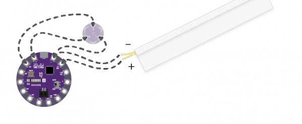
Viewing all 1123 articles
Browse latest View live


<script src="https://jsc.adskeeper.com/r/s/rssing.com.1596347.js" async> </script>