Quantcast
Channel: SparkFun Tutorials
Viewing all 1123 articles
Browse latest View live

Qwiic Micro OLED Hookup Guide

$
0
0

Qwiic Micro OLED Hookup Guide a learn.sparkfun.com tutorial

Available online at: http://sfe.io/t718

Introduction

The Qwiic Micro OLED is a Qwiic enabled version of our micro OLED display! This small monochrome, blue-on-black OLED display displays incredibly clear images

SparkFun Micro OLED Breakout (Qwiic)

LCD-14532
$14.95

This hookup guide will show you how to get started drawing objects and characters on your OLED.

Required Materials

To get started, you’ll need a microcontroller to, well, control everything.

SparkFun RedBoard - Programmed with Arduino

DEV-13975
$19.95
18
SparkFun ESP32 Thing

DEV-13907
$19.95
52
Raspberry Pi 3

DEV-13825
$39.95
85
Particle Photon (Headers)

WRL-13774
$19.00
27

Now to get into the Qwiic ecosystem, the key will be one of the following Qwiic shields to match your preference of microcontroller:

SparkFun Qwiic HAT for Raspberry Pi

DEV-14459
$4.95
SparkFun Qwiic Shield for Arduino

DEV-14352
$5.95
Qwiic Shield for Photon

SPX-14202
$1.00
Qwiic Shield for ESP32

SPX-14203
Retired

You will also need a Qwiic cable to connect the shield to your OLED, choose a length that suits your needs.

Qwiic Cable - 500mm

PRT-14429
$1.95
Qwiic Cable - 100mm

PRT-14427
$1.50
Qwiic Cable - 200mm

PRT-14428
$1.50
Qwiic Cable - 50mm

PRT-14426
$0.95

Suggested Reading

If you aren’t familiar with our new Qwiic system, we recommend reading here for an overview. We would also recommend taking a look at the following tutorials if you aren’t familiar with them.

I2C

An introduction to I2C, one of the main embedded communications protocols in use today.

Qwiic Shield for Arduino & Photon Hookup Guide

Get started with our Qwiic ecosystem with the Qwiic shield for Arduino or Photon.

Hardware Overview

Listed below are some of the operating ranges and characteristics of the Qwiic Micro OLED.

CharacteristicRange
Voltage3.3V
Temperature-40°C to 85°C
I2C Address0X3D (Default) or 0X3C (Closed Jumper)

Pins

PinDescriptionDirection
GNDGroundIn
3.3VPowerIn
SDADataIn
SCLClockIn

Optional Features

There are several jumpers on board that can be changed to facilitate several different functions. The first of which is the I2C pull-up jumper, highlighted below. If you have your own I2C pull ups, you can remove the solder from this jumper.

I2C Pull-Up Jumper

The ADDR jumper (highlighted below) can be used to change the I2C address of the board. The default jumper is open by default, pulling the address pin high and giving us an I2C address of 0X3D. Closing this jumper will ground the address pin, giving us an I2C address of 0X3C.

Address Jumper

Hardware Assembly

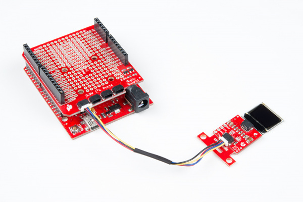
If you haven’t yet assembled your Qwiic Shield, now would be the time to head on over to that tutorial. With the shield assembled, Sparkfun’s new Qwiic environment means that connecting the screen could not be easier. Just plug one end of the Qwiic cable into the OLED display, the other into the Qwiic Shield and you’ll be ready to start displaying images on your little display.

Qwiic Micro OLED Connected to Arduino and Qwiic Shield

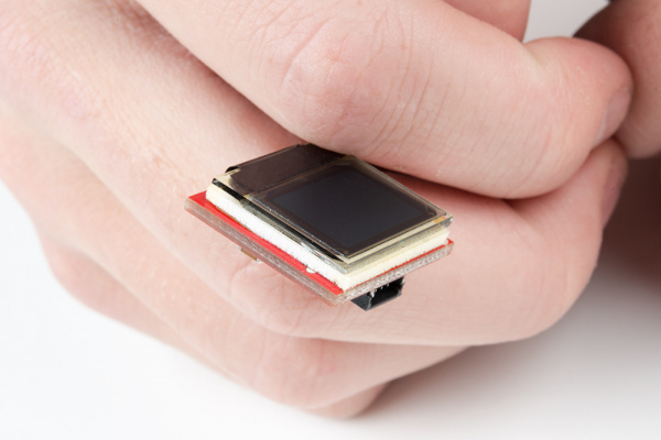
The OLED screen itself is loosely attached to the breakout board initially, so be careful handling it! You can either use your own enclosure for the OLED display, or you can use some double sided foam tape for a less permanent solution.

Taped Screen

Library Overview

Note: This example assumes you are using the latest version of the Arduino IDE on your desktop. If this is your first time using Arduino, please review our tutorial on installing the Arduino IDE. If you have not previously installed an Arduino library, please check out our installation guide.

First, you’ll need to download and install the Sparkfun Micro OLED library. Also download the Qwiic example sketches, which we will be reviewing in this tutorial.

Download the SparkFun Micro OLED Library

Download the SparkFun Qwiic Micro OLED Example Sketches

Before we get started developing a sketch, let’s look at the available functions of the library.

  • void command(uint8_t c);— Sends the display a command byte.
  • void data(uint8_t c);— Sends the display a data byte.
  • void setColumnAddress(uint8_t add);— Sets the column address.
  • void setPageAddress(uint8_t add);— Sets the page address.

LCD Drawing Functions

  • void clear(uint8_t mode):— Clears the screen buffer in the OLED’s memory, pass in mode = ALL to clear GDRAM in the OLED controller. Pass in mode = PAGE to clear the screen page buffer.
  • void clear(uint8_t mode, uint8_t c);— clears the screen buffer in the OLED’s memory, replaces it with a character ‘c’.
  • void invert(boolean inv);— Turns every black pixel white, turns all white pixels black.
  • void contrast(uint8_t contrast);— Changes the contrast value anywhere between 0 and 255.
  • void display(void);— Moves display memory to the screen to draw the image in memory.
  • void setCursor(uint8_t x, uint8_t y);— Set cursor position to (x, y).
  • void pixel(uint8_t x, uint8_t y);— Draw a pixel using the current fore color and current draw mode in the screen buffer’s x,y position.
  • void pixel(uint8_t x, uint8_t y, uint8_t color, uint8_t mode);— Draw a pixel with NORM or XOR draw mode in the screen buffer’s x,y position.
  • void line(uint8_t x0, uint8_t y0, uint8_t x1, uint8_t y1);— Draw line using current fore color and current draw mode from x0,y0 to x1,y1 of the screen buffer.
  • void line(uint8_t x0, uint8_t y0, uint8_t x1, uint8_t y1, uint8_t color, uint8_t mode);— Draw line using color and mode from x0,y0 to x1,y1 of the screen buffer.
  • void lineH(uint8_t x, uint8_t y, uint8_t width);— Draw horizontal line using current fore color and current draw mode from x,y to x+width,y of the screen buffer.
  • void lineH(uint8_t x, uint8_t y, uint8_t width, uint8_t color, uint8_t mode);— Draw horizontal line using color and mode from x,y to x+width,y of the screen buffer.
  • void lineV(uint8_t x, uint8_t y, uint8_t height);— Draw vertical line using current fore color and current draw mode from x,y to x,y+height of the screen buffer.
  • void lineV(uint8_t x, uint8_t y, uint8_t height, uint8_t color, uint8_t mode);— Draw vertical line using color and mode from x,y to x,y+height of the screen buffer.
  • void rect(uint8_t x, uint8_t y, uint8_t width, uint8_t height);— Draw rectangle using current fore color and current draw mode from x,y to x+width,y+height of the screen buffer.
  • void rect(uint8_t x, uint8_t y, uint8_t width, uint8_t height, uint8_t color , uint8_t mode);—Draw rectangle using color and mode from x,y to x+width,y+height of the screen buffer.
  • void rectFill(uint8_t x, uint8_t y, uint8_t width, uint8_t height);— Draw filled rectangle using current fore color and current draw mode from x,y to x+width,y+height of the screen buffer.
  • void rectFill(uint8_t x, uint8_t y, uint8_t width, uint8_t height, uint8_t color , uint8_t mode);— Draw filled rectangle using color and mode from x,y to x+width,y+height of the screen buffer.
  • void circle(uint8_t x, uint8_t y, uint8_t radius);— Draw circle with radius using current fore color and current draw mode with center at x,y of the screen buffer.
  • void circle(uint8_t x, uint8_t y, uint8_t radius, uint8_t color, uint8_t mode);— Draw circle with radius using color and mode with center at x,y of the screen buffer.
  • void circleFill(uint8_t x0, uint8_t y0, uint8_t radius);— Draw filled circle with radius using current fore color and current draw mode with center at x,y of the screen buffer.
  • void circleFill(uint8_t x0, uint8_t y0, uint8_t radius, uint8_t color, uint8_t mode);— Draw filled circle with radius using color and mode with center at x,y of the screen buffer.
  • void drawChar(uint8_t x, uint8_t y, uint8_t c);
  • void drawChar(uint8_t x, uint8_t y, uint8_t c, uint8_t color, uint8_t mode);
  • void drawBitmap(uint8_t * bitArray);
  • uint8_t getLCDWidth(void);— Gets the width of the LCD as a byte.
  • uint8_t getLCDHeight(void);— Gets the height of the LCD as a byte.
  • void setColor(uint8_t color);
  • void setDrawMode(uint8_t mode);
  • uint8_t *getScreenBuffer(void);

Font Settings

  • uint8_t getFontWidth(void);— Gets the current font width as a byte.
  • uint8_t getFontHeight(void);— Gets the current font height as a byte.
  • uint8_t getTotalFonts(void);— Return the total number of fonts loaded into the MicroOLED’s flash memory.
  • uint8_t getFontType(void);— Returns the font type number of the current font (Font types shown below).
  • uint8_t setFontType(uint8_t type);— Sets the font type (Font types shown below).
Font TypeMaximum ColumnsMaximum RowsDescription
0106Smallest, 5x7-pixel characters.
163Medium, 8x16-pixel characters.
2537-segment display style characters, 10x16-pixels each.
351Large, 12x48 (the entire screen height) characters.

  • uint8_t getFontStartChar(void);— Returns the starting ASCII character of the current font.
  • uint8_t getFontTotalChar(void);— Return the total characters of the current font.

Rotation and Scrolling

  • void scrollRight(uint8_t start, uint8_t stop);
  • void scrollLeft(uint8_t start, uint8_t stop);
  • void scrollVertRight(uint8_t start, uint8_t stop);
  • void scrollVertLeft(uint8_t start, uint8_t stop);
  • void scrollStop(void);
  • void flipVertical(boolean flip);
  • void flipHorizontal(boolean flip);

Examples

Example: Feature Demo

This first example demonstrates many of the available features of the screen through several applications. Keep in mind when looking at this example that drawing anything takes two steps. You must first write what you want the screen to display into the screens memory, then you must tell the screen to display what is in its memory. To begin, we must include our Wire library to use I2C, and the SFE_MicroOLED library to control the screen. Then the code initializes the OLED using DC_JUMPER = 1. If you have closed the jumper on the breakout board, use DC_JUMPER = 0.

language:c
#include <Wire.h>  // Include Wire if you're using I2C
#include <SFE_MicroOLED.h>  // Include the SFE_MicroOLED library
#define PIN_RESET 9
#define DC_JUMPER 1
MicroOLED oled(PIN_RESET, DC_JUMPER);    // I2C declaration

void setup()
{
  delay(100);
  oled.begin();    // Initialize the OLED
  oled.clear(ALL); // Clear the display's internal memory
  oled.display();  // Display what's in the buffer (splashscreen)
  delay(1000);     // Delay 1000 ms
  oled.clear(PAGE); // Clear the buffer.

  randomSeed(analogRead(A0) + analogRead(A1));
}

The code below tells the microcontroller how to print each example. This is a good place to look to see examples of how the functions discussed earlier are implemented.

language:c
void lineExample()
{
  int middleX = oled.getLCDWidth() / 2;
  int middleY = oled.getLCDHeight() / 2;
  int xEnd, yEnd;
  int lineWidth = min(middleX, middleY);

  printTitle("Lines!", 1);

  for (int i=0; i<3; i++)
  {
    for (int deg=0; deg<360; deg+=15)
    {
      xEnd = lineWidth * cos(deg * PI / 180.0);
      yEnd = lineWidth * sin(deg * PI / 180.0);

      oled.line(middleX, middleY, middleX + xEnd, middleY + yEnd);
      oled.display();
      delay(10);
    }
    for (int deg=0; deg<360; deg+=15)
    {
      xEnd = lineWidth * cos(deg * PI / 180.0);
      yEnd = lineWidth * sin(deg * PI / 180.0);

      oled.line(middleX, middleY, middleX + xEnd, middleY + yEnd, BLACK, NORM);
      oled.display();
      delay(10);
    }
  }
}

void shapeExample()
{
  printTitle("Shapes!", 0);

  // Silly pong demo. It takes a lot of work to fake pong...
  int paddleW = 3;  // Paddle width
  int paddleH = 15;  // Paddle height
  // Paddle 0 (left) position coordinates
  int paddle0_Y = (oled.getLCDHeight() / 2) - (paddleH / 2);
  int paddle0_X = 2;
  // Paddle 1 (right) position coordinates
  int paddle1_Y = (oled.getLCDHeight() / 2) - (paddleH / 2);
  int paddle1_X = oled.getLCDWidth() - 3 - paddleW;
  int ball_rad = 2;  // Ball radius
  // Ball position coordinates
  int ball_X = paddle0_X + paddleW + ball_rad;
  int ball_Y = random(1 + ball_rad, oled.getLCDHeight() - ball_rad);//paddle0_Y + ball_rad;
  int ballVelocityX = 1;  // Ball left/right velocity
  int ballVelocityY = 1;  // Ball up/down velocity
  int paddle0Velocity = -1;  // Paddle 0 velocity
  int paddle1Velocity = 1;  // Paddle 1 velocity

  //while(ball_X >= paddle0_X + paddleW - 1)
  while ((ball_X - ball_rad > 1) &&
         (ball_X + ball_rad < oled.getLCDWidth() - 2))
  {
    // Increment ball's position
    ball_X+=ballVelocityX;
    ball_Y+=ballVelocityY;
    // Check if the ball is colliding with the left paddle
    if (ball_X - ball_rad < paddle0_X + paddleW)
    {
      // Check if ball is within paddle's height
      if ((ball_Y > paddle0_Y) && (ball_Y < paddle0_Y + paddleH))
      {
        ball_X++;  // Move ball over one to the right
        ballVelocityX = -ballVelocityX; // Change velocity
      }
    }
    // Check if the ball hit the right paddle
    if (ball_X + ball_rad > paddle1_X)
    {
      // Check if ball is within paddle's height
      if ((ball_Y > paddle1_Y) && (ball_Y < paddle1_Y + paddleH))
      {
        ball_X--;  // Move ball over one to the left
        ballVelocityX = -ballVelocityX; // change velocity
      }
    }
    // Check if the ball hit the top or bottom
    if ((ball_Y <= ball_rad) || (ball_Y >= (oled.getLCDHeight() - ball_rad - 1)))
    {
      // Change up/down velocity direction
      ballVelocityY = -ballVelocityY;
    }
    // Move the paddles up and down
    paddle0_Y += paddle0Velocity;
    paddle1_Y += paddle1Velocity;
    // Change paddle 0's direction if it hit top/bottom
    if ((paddle0_Y <= 1) || (paddle0_Y > oled.getLCDHeight() - 2 - paddleH))
    {
      paddle0Velocity = -paddle0Velocity;
    }
    // Change paddle 1's direction if it hit top/bottom
    if ((paddle1_Y <= 1) || (paddle1_Y > oled.getLCDHeight() - 2 - paddleH))
    {
      paddle1Velocity = -paddle1Velocity;
    }

    // Draw the Pong Field
    oled.clear(PAGE);  // Clear the page
    // Draw an outline of the screen:
    oled.rect(0, 0, oled.getLCDWidth() - 1, oled.getLCDHeight());
    // Draw the center line
    oled.rectFill(oled.getLCDWidth()/2 - 1, 0, 2, oled.getLCDHeight());
    // Draw the Paddles:
    oled.rectFill(paddle0_X, paddle0_Y, paddleW, paddleH);
    oled.rectFill(paddle1_X, paddle1_Y, paddleW, paddleH);
    // Draw the ball:
    oled.circle(ball_X, ball_Y, ball_rad);
    // Actually draw everything on the screen:
    oled.display();
    delay(25);  // Delay for visibility
  }
  delay(1000);
}

void textExamples()
{
  printTitle("Text!", 1);

  // Demonstrate font 0. 5x8 font
  oled.clear(PAGE);     // Clear the screen
  oled.setFontType(0);  // Set font to type 0
  oled.setCursor(0, 0); // Set cursor to top-left
  // There are 255 possible characters in the font 0 type.
  // Lets run through all of them and print them out!
  for (int i=0; i<=255; i++)
  {
    // You can write byte values and they'll be mapped to
    // their ASCII equivalent character.
    oled.write(i);  // Write a byte out as a character
    oled.display(); // Draw on the screen
    delay(10);      // Wait 10ms
    // We can only display 60 font 0 characters at a time.
    // Every 60 characters, pause for a moment. Then clear
    // the page and start over.
    if ((i%60 == 0) && (i != 0))
    {
      delay(500);           // Delay 500 ms
      oled.clear(PAGE);     // Clear the page
      oled.setCursor(0, 0); // Set cursor to top-left
    }
  }
  delay(500);  // Wait 500ms before next example

  // Demonstrate font 1. 8x16. Let's use the print function
  // to display every character defined in this font.
  oled.setFontType(1);  // Set font to type 1
  oled.clear(PAGE);     // Clear the page
  oled.setCursor(0, 0); // Set cursor to top-left
  // Print can be used to print a string to the screen:
  oled.print(" !\"#$%&'()*+,-./01234");
  oled.display();       // Refresh the display
  delay(1000);          // Delay a second and repeat
  oled.clear(PAGE);
  oled.setCursor(0, 0);
  oled.print("56789:;<=>?@ABCDEFGHI");
  oled.display();
  delay(1000);
  oled.clear(PAGE);
  oled.setCursor(0, 0);
  oled.print("JKLMNOPQRSTUVWXYZ[\\]^");
  oled.display();
  delay(1000);
  oled.clear(PAGE);
  oled.setCursor(0, 0);
  oled.print("_`abcdefghijklmnopqrs");
  oled.display();
  delay(1000);
  oled.clear(PAGE);
  oled.setCursor(0, 0);
  oled.print("tuvwxyz{|}~");
  oled.display();
  delay(1000);

  // Demonstrate font 2. 10x16. Only numbers and '.' are defined.
  // This font looks like 7-segment displays.
  // Lets use this big-ish font to display readings from the
  // analog pins.
  for (int i=0; i<25; i++)
  {
    oled.clear(PAGE);            // Clear the display
    oled.setCursor(0, 0);        // Set cursor to top-left
    oled.setFontType(0);         // Smallest font
    oled.print("A0: ");          // Print "A0"
    oled.setFontType(2);         // 7-segment font
    oled.print(analogRead(A0));  // Print a0 reading
    oled.setCursor(0, 16);       // Set cursor to top-middle-left
    oled.setFontType(0);         // Repeat
    oled.print("A1: ");
    oled.setFontType(2);
    oled.print(analogRead(A1));
    oled.setCursor(0, 32);
    oled.setFontType(0);
    oled.print("A2: ");
    oled.setFontType(2);
    oled.print(analogRead(A2));
    oled.display();
    delay(100);
  }

  // Demonstrate font 3. 12x48. Stopwatch demo.
  oled.setFontType(3);  // Use the biggest font
  int ms = 0;
  int s = 0;
  while (s <= 5)
  {
    oled.clear(PAGE);     // Clear the display
    oled.setCursor(0, 0); // Set cursor to top-left
    if (s < 10)
      oled.print("00");   // Print "00" if s is 1 digit
    else if (s < 100)
      oled.print("0");    // Print "0" if s is 2 digits
    oled.print(s);        // Print s's value
    oled.print(":");      // Print ":"
    oled.print(ms);       // Print ms value
    oled.display();       // Draw on the screen
    ms++;         // Increment ms
    if (ms >= 10) // If ms is >= 10
    {
      ms = 0;     // Set ms back to 0
      s++;        // and increment s
    }
  }
}

// Center and print a small title
// This function is quick and dirty. Only works for titles one
// line long.
void printTitle(String title, int font)
{
  int middleX = oled.getLCDWidth() / 2;
  int middleY = oled.getLCDHeight() / 2;

  oled.clear(PAGE);
  oled.setFontType(font);
  // Try to set the cursor in the middle of the screen
  oled.setCursor(middleX - (oled.getFontWidth() * (title.length()/2)),
                 middleY - (oled.getFontWidth() / 2));
  // Print the title:
  oled.print(title);
  oled.display();
  delay(1500);
  oled.clear(PAGE);
}

The example code will then loop between all of the examples. This is a good way to see exactly what your code looks like on the screen.

void loop()
{
  lineExample();   // Then the line example function
  shapeExample();  // Then the shape example
  textExamples();  // Finally the text example
}

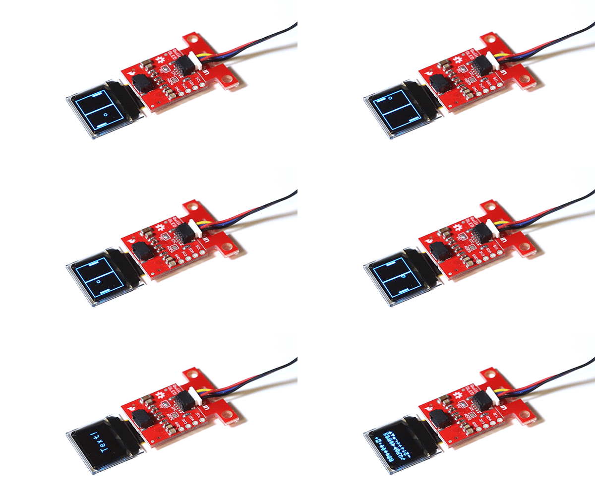
The example code will look something like the GIF below.

Qwiic Micro OLED Demo

Example: Drawing Bitmaps

It is also possible to load bitmaps of your own custom images into the screen. This can be done using this Bitmap generator. The tool is pretty self explanatory, just load in an image, tell the tool that your screen is 64x48, go to File, and Save the output.

Bitmap Converter Program

Open the file generated as a text file, it should look something like the below image.

Generated Text File

This array is the image that will be displayed by the screen, so now we just have to paste it into the bitmaps.h header file as the correct data type so our compiler is able to find the image. Make sure you change the array to a uint8_t. The pasted bitmap should looke something like the below image, with the variable type changed to uint8_t.

Include the Bitmap Header File

Now we will be able to call drawBitmap(Untitled) to draw our image. Some example code showing how to display some Rick and Morty bitmaps is shown below.

language:c
#include <Wire.h>  // Include Wire if you're using I2C
#include <SFE_MicroOLED.h>  // Include the SFE_MicroOLED library
#include "bitmaps.h"

//The library assumes a reset pin is necessary. The Qwiic OLED has RST hard-wired, so pick an arbitrarty IO pin that is not being used
#define PIN_RESET 9
//The DC_JUMPER is the I2C Address Select jumper. Set to 1 if the jumper is open (Default), or set to 0 if it's closed.
#define DC_JUMPER 0

MicroOLED oled(PIN_RESET, DC_JUMPER);    // I2C declaration

void setup()
{
  delay(100);
  oled.begin();    // Initialize the OLED
  oled.clear(ALL); // Clear the display's internal memory
  oled.display();  // Display what's in the buffer (splashscreen)
  delay(1000);     // Delay 1000 ms
  oled.clear(PAGE); // Clear the buffer.

}

void loop()
{
    drawRick();
    delay(5000);
    drawMorty();
    delay(5000);
}

void drawRick()
{
    oled.clear(ALL);
    oled.clear(PAGE);
    oled.drawBitmap(rick);//Display Logo
    oled.display();
}

void drawMorty()
{
    oled.clear(ALL);
    oled.clear(PAGE);
    oled.drawBitmap(morty);//Display Logo
    oled.display();
}

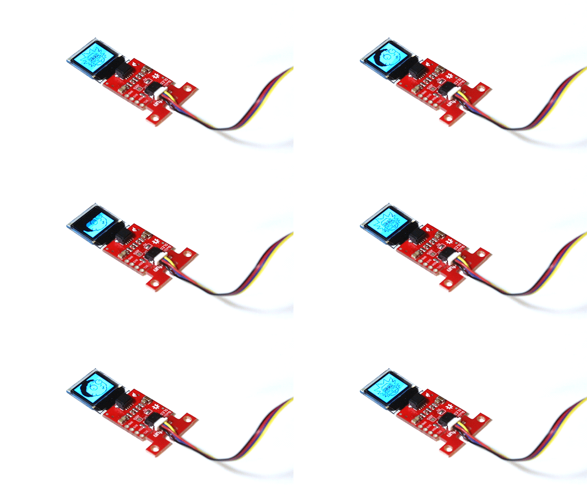
The output of this code will look something like the GIF below.

Morty Rick Displayed on the Qwiic Enabled Micro OLED

Resources and Going Further

Now that you’ve successfully got your OLED displaying things, it’s time to incorporate it into your own project!

For more on the Qwiic Micro OLED, check out the links below:

Need some inspiration for your next project? Check out some of these related tutorials:

Micro OLED Breakout Hookup Guide

Learn how to hook up the Micro OLED breakout to an Arduino. Then draw pixels, shapes, text and bitmaps all over it!

Photon OLED Shield Hookup Guide

The Photon OLED Shield has everything you need to add a small yet crisp OLED screen to your Photon projects. This hookup guide will show you how to get started.

MicroView Hookup Guide

A quick tutorial to get you up and running with your MicroView Development Board.

learn.sparkfun.com |CC BY-SA 3.0 | SparkFun Electronics | Niwot, Colorado


LilyPad Temperature Sensor Hookup Guide

$
0
0

LilyPad Temperature Sensor Hookup Guide a learn.sparkfun.com tutorial

Available online at: http://sfe.io/t437

Introduction

The LilyPad Temperature Sensor lets you detect temperature changes in the environment (or an object pressed against the sensor) on your wearable project.

LilyPad Temperature Sensor

DEV-08777
$3.95

The temperature sensor board will output specific voltage at set temperatures - 10mV for every degree Celsius (°C), with 0 degrees C set at 0.5V. The current flowing through the signal tab can be read by an analog tab on a LilyPad Arduino board and converted through a formula to degrees in Celsius or Fahrenheit. Follow along to learn how to convert the voltage from the sensor into usable temperature data in your project.

You will need to connect the sensor to a LilyPad Arduino or other microcontroller to read the output values and use in your code.

Required Materials

To follow along with the code examples, we recommend:

Suggested Reading

To add this sensor to a project, you should be comfortable sewing with conductive thread and uploading code to your LilyPad Arduino. Here are some tutorials to review before working with this sensor:

What is a Circuit?

Every electrical project starts with a circuit. Don't know what a circuit is? We're here to help.

Planning a Wearable Electronics Project

Tips and tricks for brainstorming and creating a wearables project.

Choosing a LilyPad Arduino for Your Project

Not sure which LilyPad Arduino is right for you? We'll discuss the features of each and help you decide.

LilyPad Basics: E-Sewing

Learn how to use conductive thread with LilyPad components.

Attaching to a LilyPad Arduino

The LilyPad Temperature Sensor has three sew tabs - Power (+), Ground (-), and Signal (S). The signal tab will be connected to an analog tab (marked with an ‘A’) on a LilyPad Arduino.

LilyPad Arduino USB

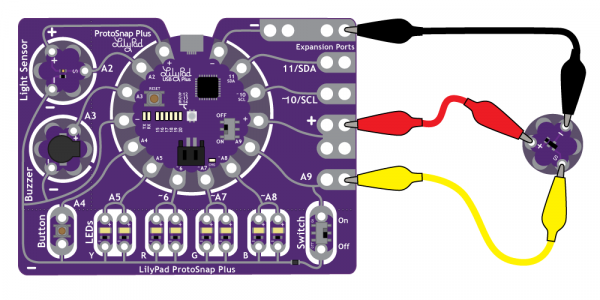
To follow along with the code examples in this tutorial, connect the temperature sensor to a LilyPad Arduino as shown below. Use alligator clips to temporarily connect Signal to A3 on a LilyPad Arduino, (-) to (-) on the LilyPad, and the (+) to (A5). When you are finished prototyping, replace the alligator clips with conductive thread traces for permanent installation in your project.

Attaching Sensor to a LilyPad USB

LilyPad ProtoSnap Plus

Attaching Sensor to a LilyPad ProtoSnap Plus

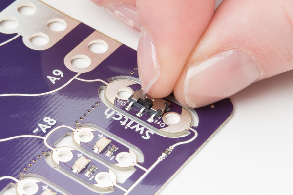
After clipping the sensor to A9, move the slide switch to the OFF position to keep the switch from interfering with your input signal.

Turn Switch OFF for A9

Other LilyPad Connection Notes:

  • If using the ProtoSnap - LilyPad Development Simple - attach to the metal tab at the top right of the board, this connects to A3. You can also set pin A5 to HIGH in your code to use it as an additional power tab, as the LilyPad Simple’s tab is hard to access in the ProtoSnap format.
  • If using the the pre-wired temperature sensor on the ProtoSnap - LilyPad Development Board, it is attached to pin A1.

Interpreting Sensor Readings

The sensor produces an analog voltage representing the temperature near it. In order to get readings in degrees, we’ll have to do some math. The voltage output from the sensor is linearly proportional to the Celsius temperature. Once you know the output voltage of the sensor, you can calculate the temperature with this equation:


To convert that reading to Fahrenheit, use this formula:


Next, we’ll be use Serial Monitor to read the values coming from the sensor and insert the formulas in our code to display the temperature in both Celcius and Farenheit.

Note: Upload the following code to your LilyPad Arduino, making sure to select the correct LilyPad board from the drop down menu below. Choose LilyPad Arduino USB if using a LilyPad Arduino USB. The LilyPad Arduino Simple, LilyPad Arduino, and LilyPad Development Board, and Development Board Simple all use a LilyPad ATmega 328. Select LilyPad USB Plus if following along with the LilyPad ProtoSnap Plus.

Don't forget to select the Serial Port that your LilyPad is connected to.

If prototyping with a LilyPad Development Board, change sensorPin to A1.
language:c

/*
LilyPad Temperature Sensor Example
SparkFun Electronics
https://www.sparkfun.com/products/8777

This code reads the input of the temperature sensor, converts it to Farenheit and Celsius
and prints to the Serial Monitor.

Temperature sensor connections:
   * S tab to A3
   * + tab to A5 (or +)
   * - tab to -

Follow the tutorial at:
https://learn.sparkfun.com/tutorials/lilypad-temperature-sensor-hookup-guide

This code is released under the MIT License (http://opensource.org/licenses/MIT)
******************************************************************************/

// Connect the S tab of the Temperature Sensor to A3
// If using the LilyPad ProtoSnap Plus, change to A9
 int sensorPin = A3;

void setup()
{
  // Set the temperature sensor pin as an INPUT:
  pinMode(sensorPin, INPUT);

  // Set pin A5 to use as a power pin for the light sensor
  // If using the LilyPad Development Board or the + tab for power, comment out these lines of code
  pinMode(A5, OUTPUT);
  digitalWrite(A5, HIGH);

  // Initialize Serial, set the baud rate to 9600 bps.
  Serial.begin(9600);
}

void loop()
{
  // Variable to store raw temperature
  long rawTemp;

  // Variable to store voltage calculation
  float voltage;

  // Variable to store Fahrenheit value
  float fahrenheit;

  // Variable to store Celsius value
  float celsius;

  // Read the raw 0-1023 value of temperature into a variable.
  rawTemp = analogRead(sensorPin);

  // Calculate the voltage, based on that value.
  // Multiply by maximum voltage (3.3V) and divide by maximum ADC value (1023).
  // If you plan on using this with a LilyPad Simple Arduino on USB power, change to 4.2
  voltage = rawTemp * (3.3 / 1023.0);
  Serial.print("Voltage: "); // Print voltage reading to serial monitor
  Serial.println(voltage);

  // Calculate the celsius temperature, based on that voltage..
  celsius = (voltage - 0.5) * 100;
  Serial.print("Celsius: "); // Print celcius temp to serial monitor
  Serial.println(celsius);

  // Use a common equation to convert celsius to Fahrenheit. F = C*9/5 + 32.
  fahrenheit = (celsius * 9.0 / 5.0) + 32.0;
  Serial.print("Fahrenheit: "); // Print Fahrenheit temp to serial monitor
  Serial.println(fahrenheit);
  // Print a blank line
  Serial.println();

  // Wait 1 second between readings
  delay(1000);
}

After uploading the code to your LilyPad Arduino, click the magnifying glass icon at the top right of your Arduino window to open the Serial Monitor window. You should begin seeing some values from the sensor. Try placing your finger over the sensor to see the readings change.

Using Values to Trigger Behaviors

Next, we’ll use some of the readings we gathered to trigger an action or behavior when the temperature is above or below a set threshold.

This example uses the built-in LED attached to pin 13 on the LilyPad Arduino.

language:c
/*
LilyPad Temperature Trigger Example
SparkFun Electronics
https://www.sparkfun.com/products/8777

This code reads the input of the temperature sensor and compares it to
a set variable named 'threshold'. If temperature is above
the thermalAlert threshold, the built-in LED on the LilyPad Arduino will turn
on. If the temperature falls below the threshold, the LED will turn off.

Temperature sensor connections:
   * S tab to A3
   * + tab to A5 (or +)
   * - tab to -

Follow the tutorial at:
https://learn.sparkfun.com/tutorials/lilypad-temperature-sensor-hookup-guide

This example is based on Thermal Alert! example in the Digital Sandbox:
https://learn.sparkfun.com/tutorials/digital-sandbox-arduino-companion/12-thermal-alert
This code is released under the MIT License (http://opensource.org/licenses/MIT)
******************************************************************************/

// Connect the S tab of the Temperature Sensor to A3
// If using the LilyPad ProtoSnap Plus, change to A9
 int sensorPin = A3;
 int alertLED = 13;

// Set temperature threshold variable to check against. If the temperature reading is above
// this number in degrees Fahrenheit, the LED will turn on
 int threshold =  80; // 80 degrees Fahrenheit

void setup()
{
  // Set the temperature sensor pin as an INPUT:
  pinMode(sensorPin, INPUT);

  // Set pin A5 to use as a power pin for the light sensor
  // If using the LilyPad Development Board or the + tab for power, comment out these lines of code
  pinMode(A5, OUTPUT);
  digitalWrite(A5, HIGH);


// Make the built-in LED an OUTPUT
  pinMode(alertLED, OUTPUT);

  // Initialize Serial, set the baud rate to 9600 bps.
  Serial.begin(9600);
}

void loop()
{
  // Variable to store raw temperature
  long rawTemp;

  // Variable to store voltage calculation
  float voltage;

  // Variable to store Fahrenheit value
  float fahrenheit;

  // Variable to store Celsius value
  float celsius;

  // Read the raw 0-1023 value of temperature into a variable.
  rawTemp = analogRead(sensorPin);

  // Calculate the voltage, based on that value.
  // Multiply by maximum voltage (3.3V) and divide by maximum ADC value (1023).
  // If you plan on using this with a LilyPad Simple Arduino on USB power, change to 4.2
  voltage = rawTemp * (3.3 / 1023.0);
  Serial.print("Voltage: "); // Print voltage reading to serial monitor
  Serial.println(voltage);

  // Calculate the celsius temperature, based on that voltage..
  celsius = (voltage - 0.5) * 100;
  Serial.print("Celsius: "); // Print celcius temp to serial monitor
  Serial.println(celsius);

  // Use a common equation to convert celsius to Fahrenheit. F = C*9/5 + 32.
  fahrenheit = (celsius * 9.0 / 5.0) + 32.0;
  Serial.print("Fahrenheit: "); // Print Fahrenheit temp to serial monitor
  Serial.println(fahrenheit);
  // Print a blank line
  Serial.println();

  // Check the temperature, and turn on the LEDs associated with the hot or cold thresholds
  if (fahrenheit >= threshold) // If the temperature rises above the threshold:
  {
    digitalWrite(alertLED, HIGH); // Turn the LED on
    Serial.println("Thermal alert!");
  } else {
    digitalWrite(alertLED, LOW); //Turn the LED off
  }
  // Wait 1 second between readings
  delay(1000);
}

In this code, we use an if() statement to compare the value of threshold to the converted analog readings from the temperature sensor stored in the fahrenheit variable. If the temperature is too hot (higher than the threshold’s set value), then the LED will turn on. If the value is lower than the threshold, the LED will turn off.

If are having trouble getting temperatures that trigger the LED, check the output of the Serial Monitor to see if there’s a better value for threshold than what is set in the example code.

Project Examples

After prototyping and testing a project with the temperature sensor you can replace the connections with conductive thread in your project. Follow this guide for an introduction to connecting LilyPad pieces with conductive thread:

LilyPad Basics: E-Sewing

December 17, 2016

Learn how to use conductive thread with LilyPad components.

Need some inspiration for your next project? Check out some of the projects below from the community.

Breathe 3.0 Scarf by Hilary Hayes

Hilary used a LilyPad Arduino, temperature sensor, conductive thread, bright white LEDs, purple wool yarn to create a scarf that illuminates with the wearer’s breath.

Breathe 3.0 Scarf by Hilary Hayes

Photo courtesy of Fashioning Technology

Hands-on-Warm by Maria Julia Guimaraes

The Hands-on-Warm project uses a LilyPad Arduino, LilyPad Temperature Sensor, and heating pad to warm the hands of people who experience extreme cold sensitivity.

Hands-on-Warm from Maria Julia Guimaraes on Vimeo.

Resources and Going Further

For more information about the LilyPad Temperature Sensor, check out the resources below:

Here are some resources for planning a project with the temperature sensor:

Insulation Techniques for e-Textiles

Learn a few different ways to protect your conductive thread and LilyPad components in your next wearables project.

Planning a Wearable Electronics Project

Tips and tricks for brainstorming and creating a wearables project.

LilyPad Light Sensor Hookup Guide

How to hook up the LilyPad Light Sensor as well as some project ideas and example code.

LilyPad Reed Switch Hookup Guide

A guide to using the LilyPad Reed Switch breakout in your projects.

learn.sparkfun.com |CC BY-SA 3.0 | SparkFun Electronics | Niwot, Colorado

AT42QT101X Capacitive Touch Breakout Hookup Guide

$
0
0

AT42QT101X Capacitive Touch Breakout Hookup Guide a learn.sparkfun.com tutorial

Available online at: http://sfe.io/t722

Introduction

If you need to add user input without using a button, then a capacitive touch interface might be the answer. The AT42QT1010 and AT42QT1011 Capacitive Touch Breakout boards offer a single capacitive touch button with easy-to-use digital I/O pins. For convenience I’ll refer to both versions of this board as “AT42QT101X” but I’ll refer to each individual version when talking about their differences.

SparkFun Capacitive Touch Breakout - AT42QT1010

SEN-12041
$5.95
8
SparkFun Capacitive Touch Breakout - AT42QT1011

SEN-14520
$5.95

The AT42QT101X is a dedicated, single-button capacitive sense chip. The chip handles monitoring a conductive area for touch. As long as a touch (e.g. from a finger) is detected, the AT42QT101X keeps the output line high. Otherwise, the line is kept low. You just need to provide a power source (1.8V - 5V) and ground for the AT42QT101X to work. SparkFun’s breakout board contains an on-board electrode capable of detecting touches. Additionally, a PAD pin is available if you would like to create your own external electrode.

Covered In This Tutorial

This tutorial will show you how to connect the AT42QT101X Breakout Board to an Arduino along with some example code to read the board’s output. Additionally, alternative ways to use the board will be shown, such as mounting it to an acrylic panel and creating your own capacitive sensing pad.

Required Materials

Suggested Reading

How to Solder: Through-Hole Soldering

This tutorial covers everything you need to know about through-hole soldering.

Working with Wire

How to strip, crimp and work with wire.

What is an Arduino?

What is this 'Arduino' thing anyway?

Switch Basics

A tutorial on electronics' most overlooked and underappreciated component: the switch! Here we explain the difference between momentary and maintained switches and what all those acronyms (NO, NC, SPDT, SPST, ...) stand for.

Light-Emitting Diodes (LEDs)

Learn the basics about LEDs as well as some more advanced topics to help you calculate requirements for projects containing many LEDs.

Capacitors

Learn about all things capacitors. How they're made. How they work. How they look. Types of capacitors. Series/parallel capacitors. Capacitor applications.

Hardware Overview

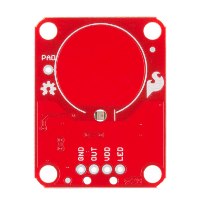
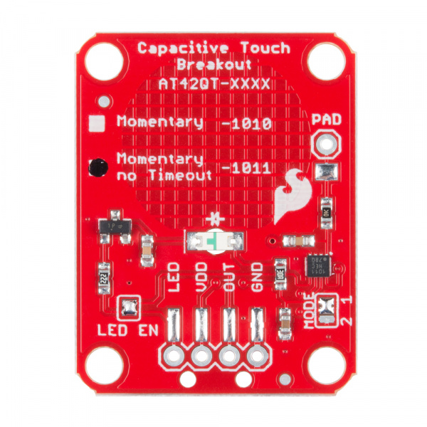
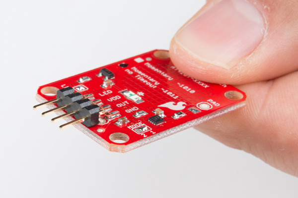
If we look at the front of the board, we see a large, circular pad (the “electrode”) and several pins. The on-board electrode will detect touches when pressed with a finger as long as the board is powered.

Front of PCB

AT42QT101X Breakout front

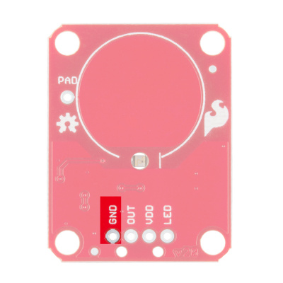
GND should be connected to the ground of the host circuit.

GROUND PTH of Capacitive Touch

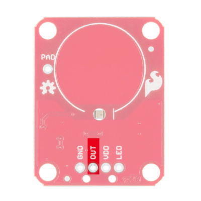
OUT is the output of the AT42QT101X. HIGH on touch, LOW otherwise.

OUT PTH of Capacitive Touch

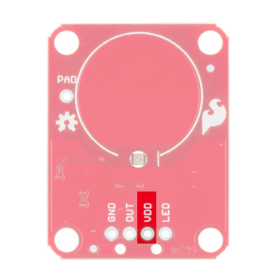
VDD is the power supply for the AT42QT101X and needs to be connected to a voltage between 1.8V - 5V.

VDD PTH of Capacitive Touch

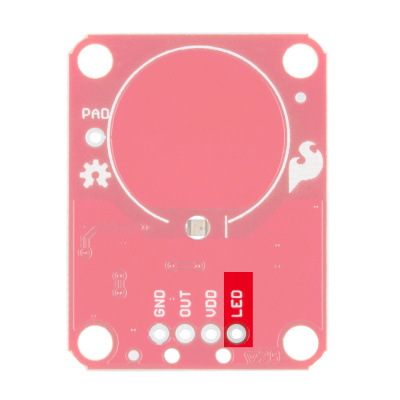
LED controls the operation of the on-board LED. By default, it is connected to the OUT pin. If you de-solder the “LED Enable” jumper on the back side, you can independently control the LED.

LED PTH of Capacitive Touch

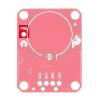
PAD is located in the upper-left corner and allows you to connect to an external electrode. Note that there is a small surface mount pad on the back side by the PAD pin hole. If you want to mount the board flush, you can solder a wire directly to the surface mount pad.

PAD PTH of Capacitive Touch

How It Works

Take a look at the back side of the AT42QT101X. Both versions share the exact same PCB layout but different IC’s (lower right “1011”).

Backside of the 1011

AT42QT1011 Breakout Back

The AT42QT101X chip is located on the right side of the board. It uses a resistor and a capacitor network to adjust the sensitivity of the electrode. High frequency pulses are sent to the pad. When a fleshy object (such as a finger) approaches the pad, it acts like a very small capacitor and changes the shape of the pulses. When the AT42QT101X detects these slight changes, it raises the OUT line to HIGH, indicating a touch is present. The duration of the output depends on the chip that is populated. Once the pulses return to normal, the AT42QT101X drives the OUT line LOW.

AT42QT1010 vs AT42QT1011

The version of your chip is indicated by the small check boxes on the back side. We offer two versions of the same chip: the AT42QT1010 and the AT42QT1011. Both boards function the same with one small caveat: the AT42QT1010 has an internal timeout of ~60 seconds where as the AT42QT1011 does not. Meaning that if you hold your finger to the AT42QT1010’s pad for more than 60 seconds than the boards' OUT pin will go low (turn itself off). The difference is small but may be a game changer depending on your project’s uses.

Note: There is an issue with the AT42QT-1011 where the IC will not stay on indefinitely when powering your microcontroller with less reliable wall warts. Powering your microcontroller through your computer's USB ports or other more steady power supplies is recommended. The issue is currently being investigated.

LED Enable

The output from the AT42QT101X goes directly to the OUT pin on the board as well as to the transistor (left side), which operates the LED (center of board). By default, the OUT line and LED lines are connected, which means that on a touch, the on-board LED lights up. You can disconnect the LED by de-soldering the jumper labeled “LED Enable.” This will cause the LED to no longer light up on a touch, but you can still drive the LED using the LED pin on the board.

Mode

On the right side of the board, you will also notice a jumper labeled “Mode” with “1” and “2” markers. By default, the center pad and the “1” pad are connected, which puts the AT42QT101X in “Fast” mode. In Fast mode, the chip is more responsive to touch events but draws 200µA - 750µA in normal operation. If you de-solder this jumper and connect the center pad to the “2” pad, the AT42QT101X will be in “Low Power” mode. In this mode, the chip is slightly less responsive to events but only uses 15µA - 75µA. Keep in mind that the current draw of the IC itself. The LED draws another 30-40mA but can be disabled by removing solder from the “LED enable” solder jumper.

Hardware Hookup

Assembly

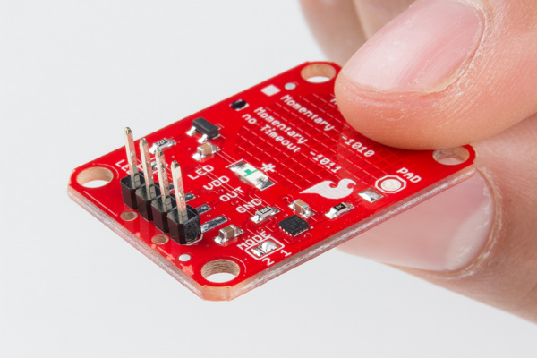
If you are not planning to mount the board flush to a panel, you can solder either wires or break away headers to the 4 header holes on the board.

Vertical PTH headers on AT42QT1011 breakout

PTH headers are recommended if you are using a breadboard.

On the other hand, if you wish to mount the AT42QT101X to a panel, you can solder a 4-pin male header to the SMD pads.

SMD Headers on AT42QT1011

SMD headers work better if you plan to mount the board to a panel

Connecting the AT42QT101X Breakout Board

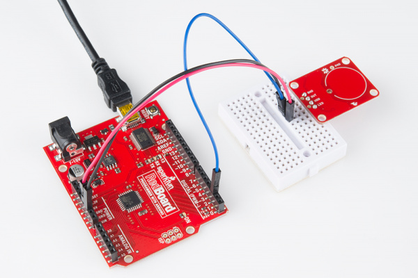
Hookup Guide of Arduino to Capactive Touch Breakout

Basic hookup using an Arduino and a breadboard

For an Arduino, make the following connections with jumper wires:

AT42QT101XArduino
VDD5V
OUT2
GNDGND

Mounting the AT42QT101X Breakout Board

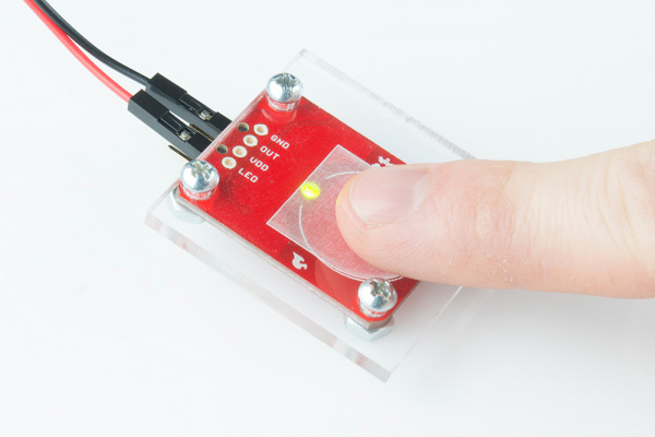
One advantage of capacitive touch boards is their ability to be mounted to panels and detect touch through thin plastic, cardboard, etc. Using a drill or laser cutter, cut four 0.125 inch holes in the same pattern as the mounting holes on the breakout board.

Attach the board to the panel using #4-40 screws and #4-40 nuts.

Capacitive Touch through Breakout!

The AT42QT101X will detect touch through 0.125 inch acrylic

External Electrode

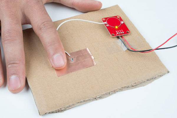
You can create your own electrode by using foil, copper tape, or any other conductive material. Cut or shape the electrode and attach a wire between the electrode and the PAD pin on the AT42QT101X breakout board. For a secure connection, make sure to solder the external electrode together. The electrode can be almost any shape and size.

External Pad

Touch can be detected on external electrodes

Example Code

Note: This example assumes you are using the latest version of the Arduino IDE on your desktop. If this is your first time using Arduino, please review our tutorial on installing the Arduino IDE.

Open the Arduino program and paste the following code into the sketch:

language:c
/*
 12-23-2013
 SparkFun Electronics 2013
 Shawn Hymel

 This code is public domain but you buy me a beer if you use this
 and we meet someday (Beerware license).

 Description:

 This sketch shows how to use the SparkFun AT42QT101X Breakout
 Board. If you touch the Capacitive Touch area on the breakout
 board, the LED attached to the Arduino will light up (in addition
 to the LED on the AT42QT101X breakout board).

 Simply connect power and ground to the breakout board,
 and the AT42QT101X handles all the capacitive touch functions.
 By default, the board will light up the green LED when the pad
 is touched. A wire may also be connected from OUT on the
 breakout board to a digital input pin on an Arduino. This signal
 is normally LOW but goes HIGH on a touch detection.

 The "LED Enable" solder jumper may be de-soldered in order to
 control the LED directly from the LED pin. This is useful if you
 want to light up a button that the user needs to push.

 Hardware connections:

 Uno Pin    AT42QT101X Board  Function

 +5V        VDD               Power supply
 GND        GND               Ground
 2          OUT               Capacitive touch state output
 */

// Constants
const int TOUCH_BUTTON_PIN = 2;  // Input pin for touch state
const int LED_PIN = 13;          // Pin number for LED

// Global Variables
int buttonState = 0;             // Variable for reading button

void setup() {

  // Configure button pin as input
  pinMode(TOUCH_BUTTON_PIN, INPUT);

  // Configure LED pin as output
  pinMode(LED_PIN, OUTPUT);

}

void loop() {

  // Read the state of the capacitive touch board
  buttonState = digitalRead(TOUCH_BUTTON_PIN);

  // If a touch is detected, turn on the LED
  if (buttonState == HIGH) {
    digitalWrite(LED_PIN, HIGH);
  } else {
    digitalWrite(LED_PIN, LOW);
  }
}

Plug in the Arduino and upload the code. You should see the LED on the AT42QT101X board and the LED on the Arduino light up when you touch the electrode.

Testing Capacitive Touch Code

The AT42QT101X detects touches, and the Arduino monitors pin 2 for the output of the AT42QT101X.

Resources and Going Further

Now that you’ve successfully got your capacitive touch breakout up and running, it’s time to incorporate it into your own project!

For more information about the board, check out the resources below:

The AT42QT101X is a great way to add a single capacitive touch button to a project. Need some inspiration for your next project? Check out some of these tutorials for ideas:

  • Create a hidden button for the Illuminated Boxes.
  • Replace the Wake-On-Shake module with a capacitive touch button for the Uncertain 7-Cube
  • Add a hidden, capacitive touch button to almost anything!

learn.sparkfun.com |CC BY-SA 3.0 | SparkFun Electronics | Niwot, Colorado

DIY Heated Earmuffs

$
0
0

DIY Heated Earmuffs a learn.sparkfun.com tutorial

Available online at: http://sfe.io/t732

Introduction

Design and build time: 5 Hours

In this project, we’ll create a wearable pair of heated earmuffs with decorative addressable LEDs. These earmuffs are embedded with a Pro Micro 5v, two heating pads, and four rings of WS2812 addressable LEDs, or ‘Neopixels’. This project is designed to keep the user extra warm while still looking stylish.

overview

Suggested Reading

Before you get started, take some time to familiarize yourself with the following:

How to Solder: Through-Hole Soldering

This tutorial covers everything you need to know about through-hole soldering.

Installing an Arduino Library

How do I install a custom Arduino library? It's easy!

Working with Wire

How to strip, crimp and work with wire.

What is an Arduino?

What is this 'Arduino' thing anyway?

Installing Arduino IDE

A step-by-step guide to installing and testing the Arduino software on Windows, Mac, and Linux.

Planning a Wearable Electronics Project

Tips and tricks for brainstorming and creating a wearables project.

Addressable LED Strip Hookup Guide

Add blinking lights to any holiday decoration with our Holiday Lights Kit.

Materials and Tools

Let’s go over all of the things you’ll need to put your project together.

You Will Also Need:

Software Installation

Arduino IDE

The Pro Micro 5V is programmable via the Arduino IDE. If this is your first time using Arduino, please review our tutorial on installing the Arduino IDE.

Installing Arduino IDE

March 26, 2013

A step-by-step guide to installing and testing the Arduino software on Windows, Mac, and Linux.

Pro Micro Drivers and Board Add-On

If this is your first time working with the Pro Micro, you may need to add drivers and the board add-on through the boards manager. Please visit the Pro Micro hookup guide for detailed instructions on installing drivers and programming a Pro Micro via the Arduino IDE.

Pro Micro Hookup Guide

Example Code

Note: This example assumes you are using the latest version of the Arduino IDE on your desktop. If this is your first time using Arduino, please review our tutorial on installing the Arduino IDE. If you have not previously installed an Arduino library, please check out our installation guide.

In this program, we will also be utilizing the Adafruit Neopixel Library. You can download the library below.

Adafruit Neopixel Library

We have provided the code for this project below. Copy and paste it into your Arduino IDE and then upload it to your board. Make sure you have the correct board selected in the boards manager as well as the port under the port drop down.

language:c
    /******************************************************************************
  earmuffs.ino
  Melissa Felderman @ SparkFun Electronics
  creation date: January 22, 2018


  Resources:
  Adafruit_NeoPixel.h - Adafruit Neopixel library and example functions

*****************************************************************************/

#include <Adafruit_NeoPixel.h>

int heatPin = 3;
int ring = 4;


Adafruit_NeoPixel strip = Adafruit_NeoPixel(80, ring, NEO_GRB + NEO_KHZ800);

void setup() {
  pinMode(heatPin, OUTPUT);
  digitalWrite(heatPin, HIGH);
  strip.begin();
  strip.setBrightness(45);
  strip.show();

}

void loop() {
  // put your main code here, to run repeatedly:
  rainbowCycle(20);

}


// Slightly different, this makes the rainbow equally distributed throughout
void rainbowCycle(uint8_t wait) {
  uint16_t i, j;
strip.setBrightness(45);
  for (j = 0; j < 256 * 5; j++) { // 5 cycles of all colors on wheel
    for (i = 0; i < strip.numPixels(); i++) {
      strip.setPixelColor(i, Wheel(((i * 256 / strip.numPixels()) + j) & 255));
    }
    strip.show();
    delay(wait);
  }
}

// Input a value 0 to 255 to get a color value.
// The colours are a transition r - g - b - back to r.
uint32_t Wheel(byte WheelPos) {
  WheelPos = 255 - WheelPos;
  if (WheelPos < 85) {
    return strip.Color(255 - WheelPos * 3, 0, WheelPos * 3);
  }
  if (WheelPos < 170) {
    WheelPos -= 85;
    return strip.Color(0, WheelPos * 3, 255 - WheelPos * 3);
  }
  WheelPos -= 170;
  return strip.Color(WheelPos * 3, 255 - WheelPos * 3, 0);
}

Understanding Your Circuit

Inside the earmuffs are four NeoPixel Rings containing a total of 80 WS2812 addressable LEDs, two 5x10cm Heating Pads, a Pro Micro 5v/18MHz, a N-Channel MOSFET, one 10k resistor, two small pieces of Snappable Protoboard, and lots Hook Up Wire. The project is powered by our Lithium Ion Battery Pack via the SparkFun microB USB Breakout. A Mini Power Switch is connected to the power source for easy user control.

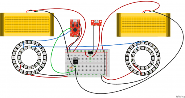
As expressed in the circuit diagram below, the Pro Micro 5v is the brains of this project. Pin 4 is connected to one of the 24x Neopixel Rings Din, with VCC connected to Raw on the Pro Micro, and GND to GND. Dout of that same Neopixel ring is connected to Din on of the 12x Neopixel Ring, VCC to VCC and GND to GND. Dout of the smaller Neopixel Ring is connected to Din on the second 24x Neopixel Ring, who’s VCC and GND are connected to Raw and GND on the Microcontroller. Dout of this ring is connected to Din of the second 12x Neopixel ring, with VCC to VCC and GND to GND.

The heating pads require about ~750mA, which is more than the microcontroller I/O pin can handle. In order to accomplish that, we will be using a N-Channel Mosfet Transisitor. One lead of each of the heating pads should connect directly to RAW on the microcontroller. The second connects to the Drain (D) lead on the transistor, or the center lead. Pin 3 on the microcontroller connects to the Gain (G) lead, which is the left lead. There is also a 10k resistor pulling the G lead down to GND. Finally, the Source (S) lead connects directly to GND.

Two long flexible wires are included in the circuit. One connects to GND and one directly to Raw. The GND wire will connect to GND on the USB Breakout. The Raw wire will connect to the center lead of the switch. Finally VCC on the USB breakout will connect with a second lead on the switch.

The Heated Earmuffs pose a unique design challenge as a wearable circuit in that the components require a 5v power supply. That’s not something you want to wear on your head. Because of this, the Heated Earmuffs have a similar physical design to headphones, with soft flexible wires connecting the circuit above with a control switch and power source in your pocket. Not only does this put the bulky power supply in a hidden location, but it also allows the user to conveniently and discretely switch the circuit on and off.

Heads up! Please note the the max current output for the battery pack used in this project is around 1A. In order to make sure the battery does not overdraw and thus overheat, we have reduced the brightness of the LEDs in the code to minimize the current draw of the circuit. Different battery packs will yield different max currents, always test while building your project.

Fritzing Diagram

Having a hard time seeing the circuit? Click on the wiring diagram for a closer look.

Building the Structure

The first part of this project is building the earmuffs structure which we will build our circuit around.

STEP 1:

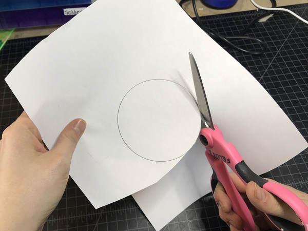
Download and print out the circles template.

Download Circles Template Here

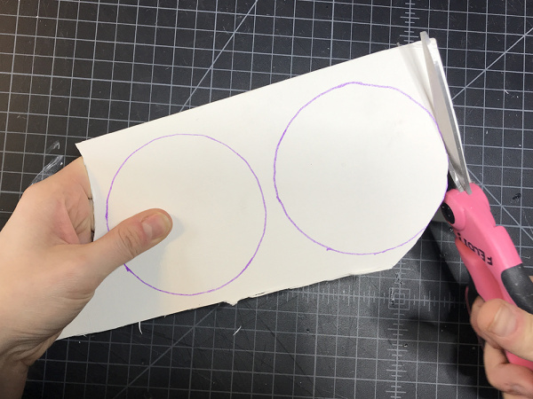
Then cut along the outline of each circle. Set aside the larger circle for later.

cut template

STEP 2:

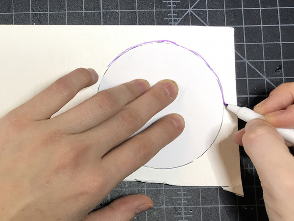
Place the smaller circle on your matte board or cardboard and trace it.

trace circle

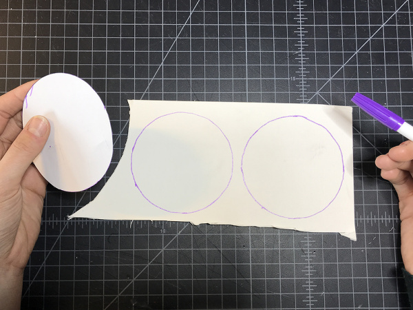
Repeat once more so that you have drawn two even circles on the matte board or card board.

repeat trace

STEP 3:

Cut out both circles.

cut circles

STEP 4:

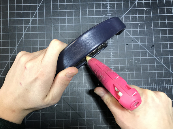
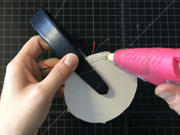
Add some hot glue to the lower inch and a half of one side of the headband.

add glue

STEP 5:

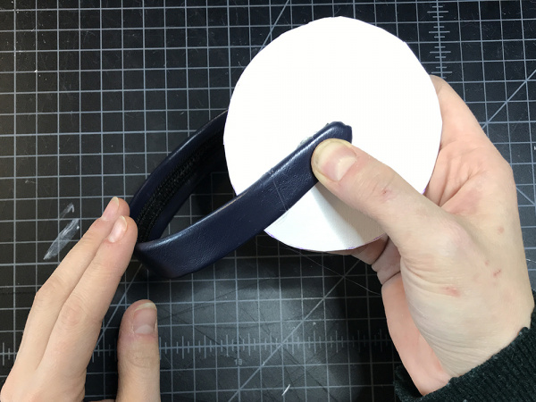
Place one of the matte board of cardboard circles to the area with hot glue. The bottom point of the headband should be at the approximate center of the circle.

glue circle

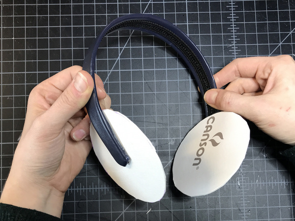
Repeat on the second side.

glue second circle

STEP 6:

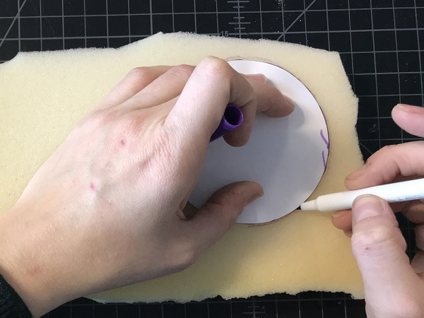
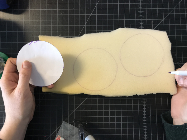
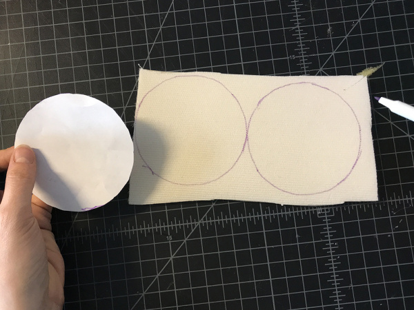
Grab the small circle template again and trace it on your foam.

trace on foam

Repeat once more so you have two circles.

second foam circle

STEP 7:

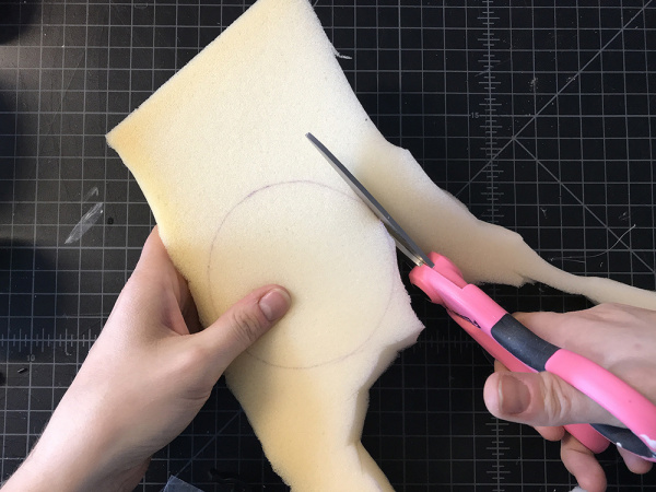
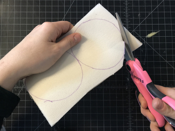
Cut out both circles from the foam.

cut foam

STEP 8:

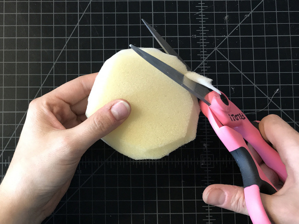
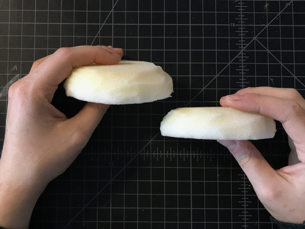
Use your scissors to sculpt one side of each foam circle into a dome.

sculpt foam

When you are done, your foam circles side view should look like this:

foam dome

STEP 9:

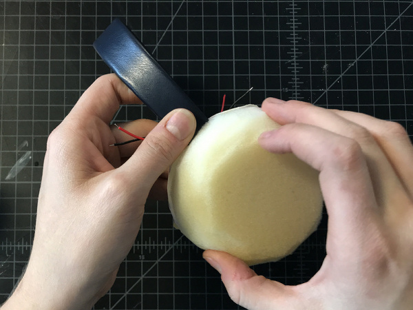
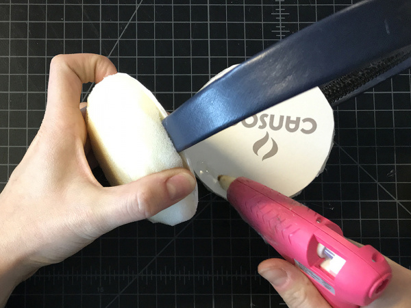
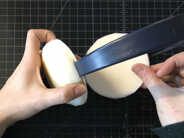
Add hot glue around the perimeter of one of the circles on the headband and then place the foam dome on top. Repeat on the second side.

add glue

place foam

STEP 10:

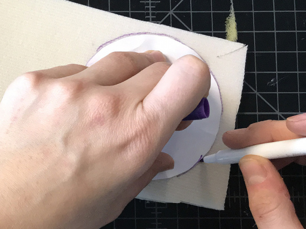
Grab the small circle template again and trace it on to interfacing twice.

trace on interfacing

repeat trace

STEP 11:

Cut out both circle from the interfacing.

cut interfacing

STEP 12:

Add hot glue to the perimeter of the inner side of your board circle, and then place the interfacing on top. Repeat this on the second side.

glue inner circle

place interfacing

Preparing Your Electronics

Now that we have build the structure of the earmuffs, let’s begin to prepare the electronics for our circuit.

STEP 13:

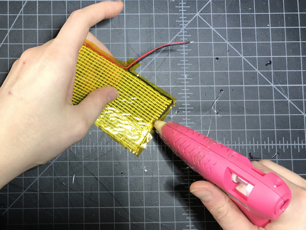
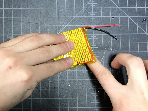
Add a small touch of hot glue to one edge of your heating pad, then fold it over making it half it’s original size.

glue heating pad

fold heating pad

STEP 14:

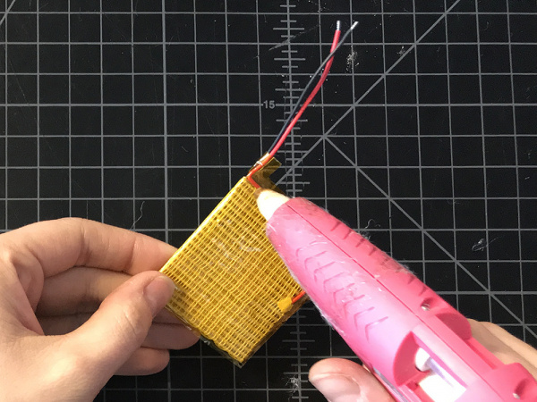
On one side of the folded pad, add hot glue to all four corners.

glue heating pad

STEP 15:

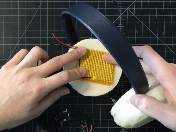
Glue it on to the interfacing, with the two leads pointing up and aligned with the leg of the headband as much as possible. Repeat for the second heating pad on the opposite side.

place heating pad

STEP 16:

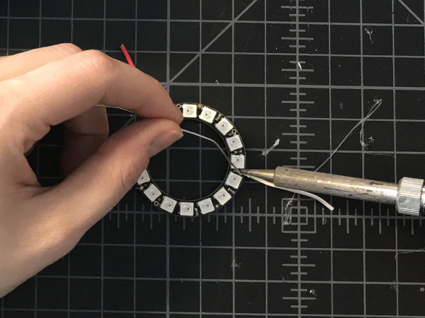
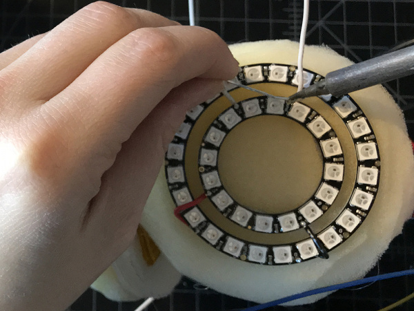
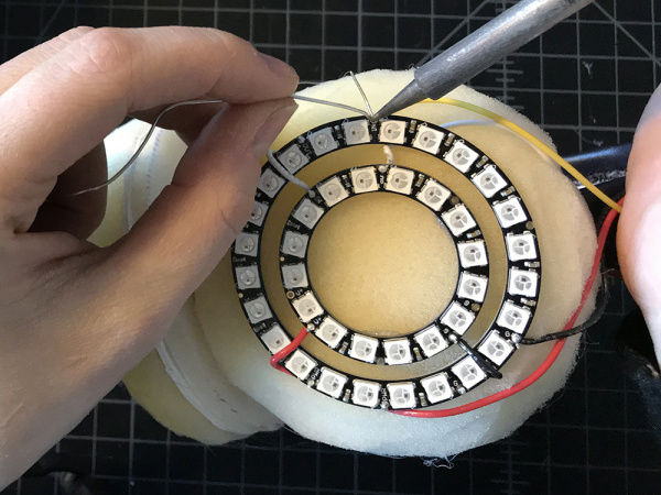
Strip a short amount of wire (about 1" - 2") and solder to both of the smaller Neopixel rings on VCC, GND, and DIN.

solder neopixel leads

STEP 17:

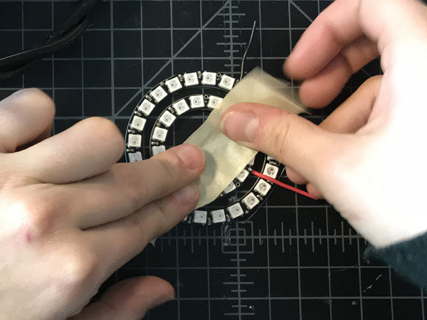
Place the larger neopixel ring around each smaller one, make sure the smaller one is relatively centered, and then add a small piece of tape over them to keep them in position.

Tape NeoPixels

STEP 18:

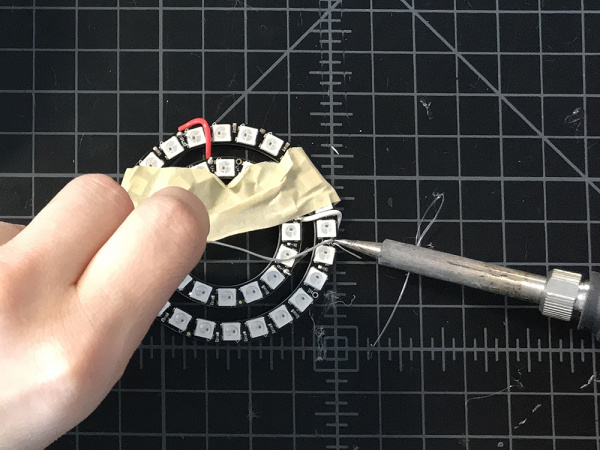
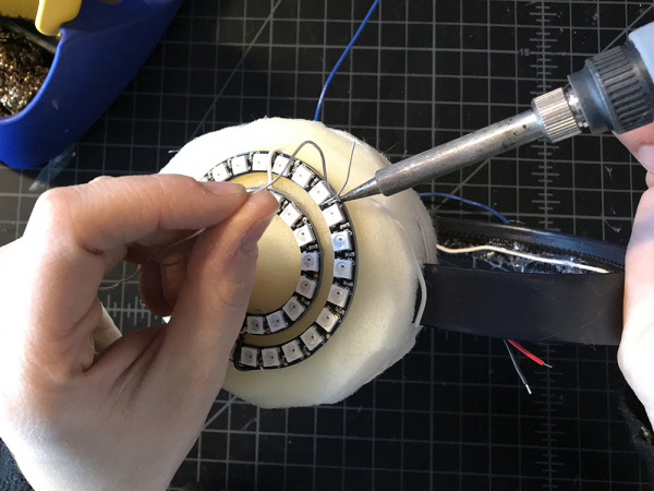
Solder the Neopixel Ring pairs together according to the circuit diagram. (From inside ring to outside ring, DIN -> DOUT, VCC -> VCC, and GND -> GND.

solder rings together

STEP 19:

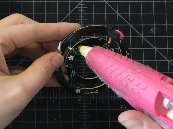
Add hot glue to the back of the smaller Neopixel ring.

glue neopixel

STEP 20:

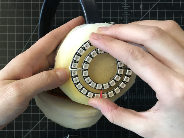
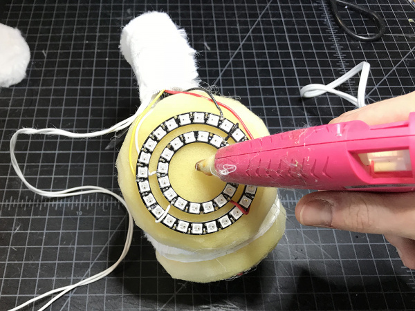
Place rings on top of the foam dome. Repeat with the second set of rings on the opposite side.

Hot Glue NeoPixel Ring

STEP 21:

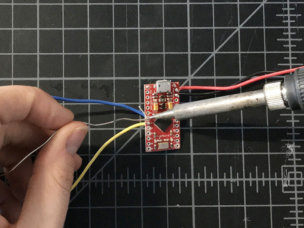
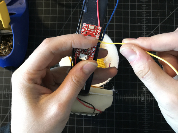
Solder medium length wire leads to Raw, GND, Pin 3 and Pin 4 on your Pro Micro.

Solder Wire to Pro Micro

STEP 22:

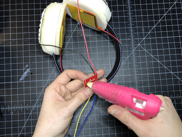
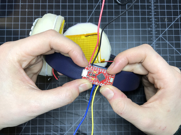
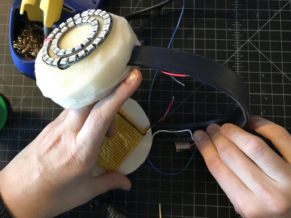
Place a small amount of hot glue to the back of the Pro Micro and then place it on the headband off to the side.

glue pro micro

place pro micro

Soldering It Together

Now that all of our parts are in place, let’s begin to solder the circuit together.

Heads up! Always test your circuit with alligator clips or on a breadboard before soldering together.

STEP 23:

Take a long piece of hook up wire and solder one end to DOUT of one of your smaller NeoPixel Rings.

DOUT

STEP 24:

Lead it along the bottom edge of the headband, hot gluing it down along the way until you make it to the opposite side.

lead wire

STEP 25:

Solder the other end to DIN of the larger ring on the opposite side. This in effect created one long LED strand of 80x WS2812 addressable LEDs.

connect rings on both sides

STEP 26:

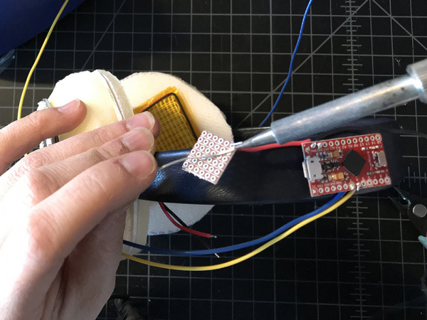
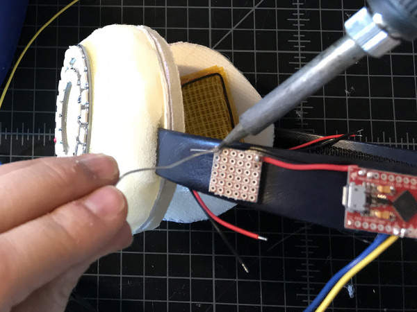
Cut the wire lead connected to Raw on the microcontroller down to about 1.5" - 2". Solder the free end to the corner of a piece of protoboard that is no wider than the headband. We will call this our Raw extension, and moving forward all connection to Raw will be made on this protoboard.

Solder raw lead

STEP 27:

Repeat step 26 for the GND wire lead. Make sure to solder it to the opposite end of the protoboard, leaving physical space between the two connections. We will call this our GND extension, and moving forward all connection to GND will be made on this protoboard.

solder gnd lead

STEP 28:

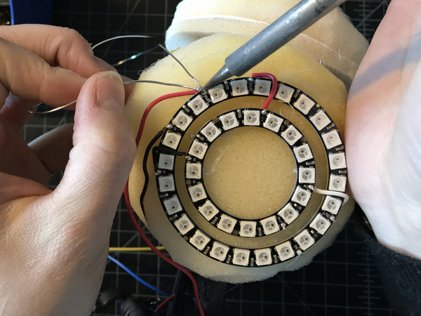
Solder a red wire lead to the Raw extension on the protoboard, and a black one to the GND extension. Take the red wire and solder it to VCC on one of the large Neopixel Rings. Take the black wire and solder it to GND on one of the large NeoPixel rings. Repeat for the second large ring on the opposite side.

Solder to Neopixel

While you are doing this, make sure to bend your wires to fit the form of the earmuffs.

bend wires

STEP 29:

Find the wire lead connected to pin 4.

find pin 4

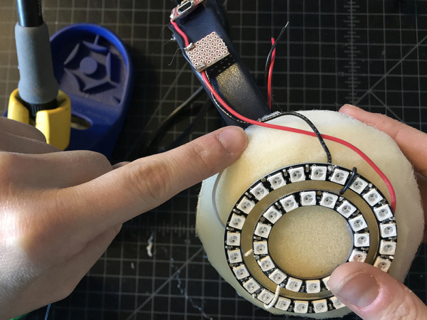
Solder this wire to the remaining DIN on your NeoPixel Ring. As we have soldered the two sides together, there should only be on DIN left for you to use.

DIN NeoPixel

STEP 30:

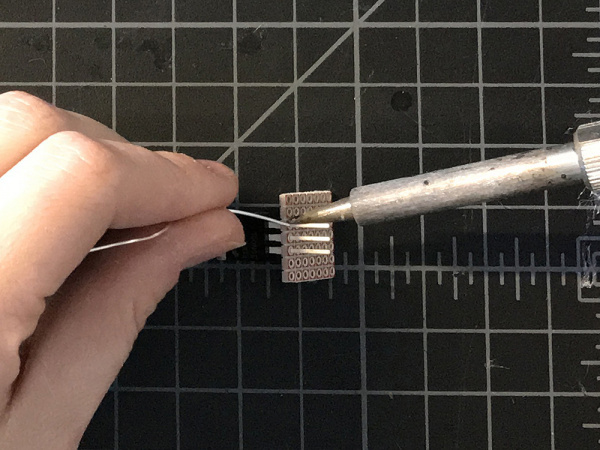
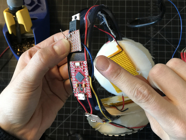
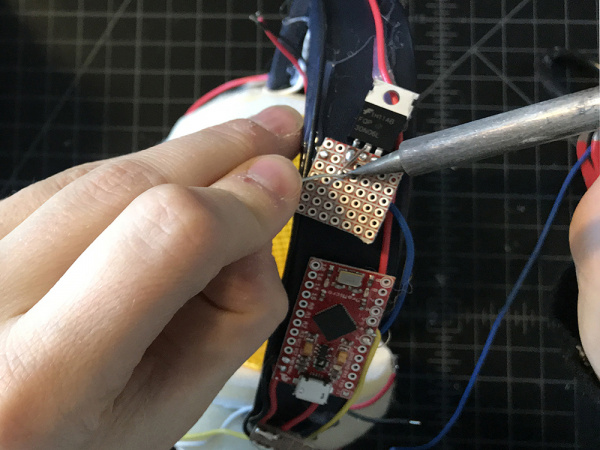
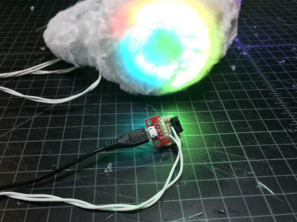
Cut a second small piece of protoboard, also no wider than the headband width, and solder the transistor along one edge.

solder transistor

STEP 31:

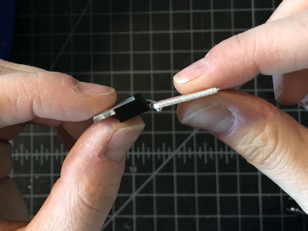
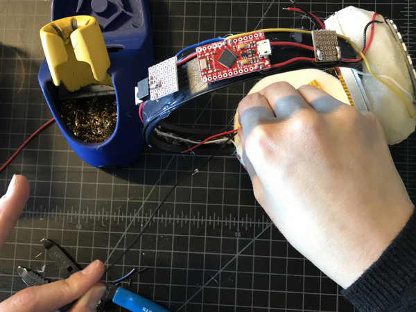
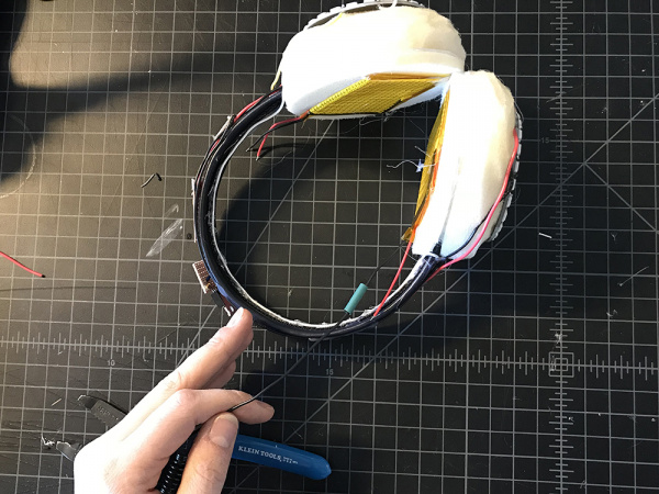
Trim the excess leads with a diagonal cutter and then fold the transistor back so that it lies flat in a plane with the protoboard.

bend transistor

STEP 32:

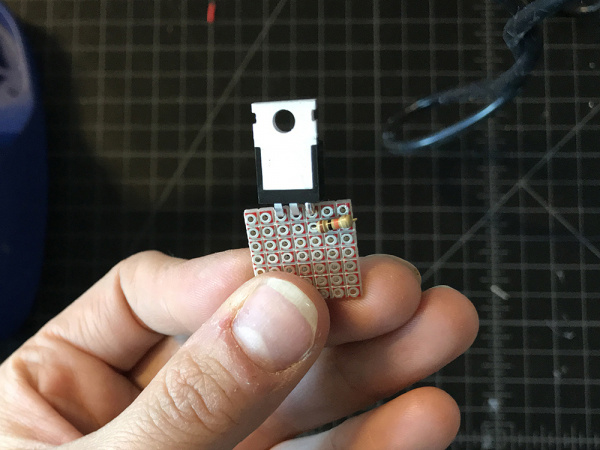
Solder a 10k resistor to the protoboard, connecting one end to the Gain (G) lead of the transistor and the other to a solder pad off to the side. Then use a jumper wire to solder the second side of the resistor to the GND extension.

solder resistor

STEP 33:

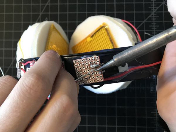
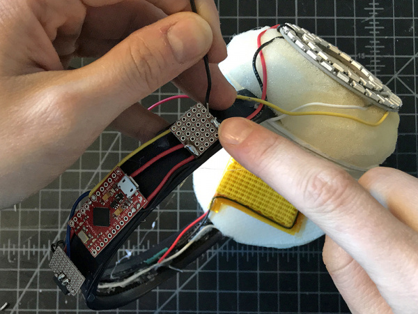
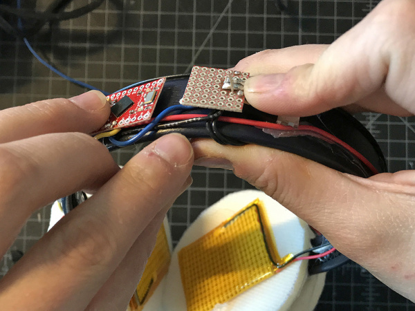
Holding the transistor protoboard to the headband with your thumb, solder the wire lead connected to pin 3 on the microcontroller to the same Gain (G) lead as the resistor on the transistor.

hold down

solder pin 3 lead

STEP 34:

Take two medium pieces of red wire and two medium pieces of black wire. Solder each red wire to the red leads on the heating pads, and each black wire to the black leads on each heating pad, in essence fabricating longer leads for the heating pads.

Heating pad leads

STEP 35:

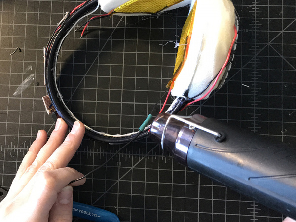
Place a small piece of heat shrink over each new connection and then use the heat gun to secure it around the soldered connections.

heat shrink

heat gun

STEP 36:

Take both black leads from the heating pads and solder them to the middle lead on your transistor - also known as the Drain (D).

Solder to drain

STEP 37:

Grab a medium black length wire and solder one end to the GND extension on the first protoboard.

GND Extension

STEP 38:

Solder the second end of that wire to the Source (S) or rightmost lead on the transistor.

Solder source

STEP 39:

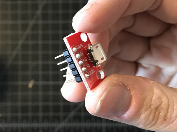
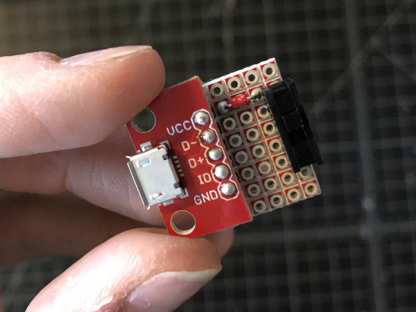
Solder header pins to your USB breakout.

header pins

STEP 40:

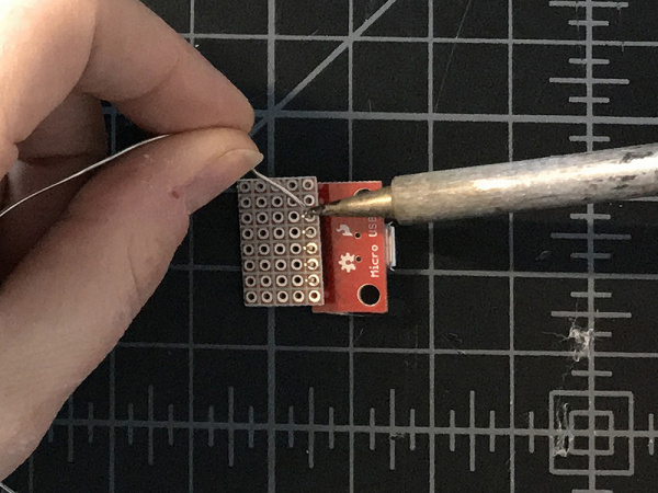
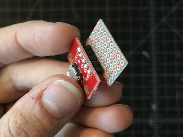
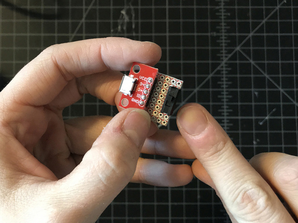
Cut a third piece of protoboard slightly wider than your USB breakout, and solder the other end of the header pins to one edge.

proto

Solder breakout

STEP 41:

Solder the switch to the opposite edge of the protoboard.

solder switch

STEP 42:

Use a very small piece of wire to connect VCC on your breakout to either the leg on the rightmost or leftmost of the switch. It does not matter which.

Solder switch

STEP 43:

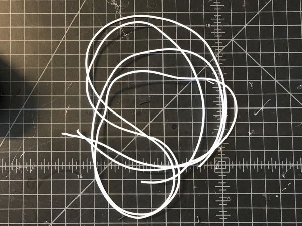
Cut two long pieces of silicone wire in white. These should be long enough to reach from the crown of your head to your pants pocket.

cut silicone wire

STEP 44:

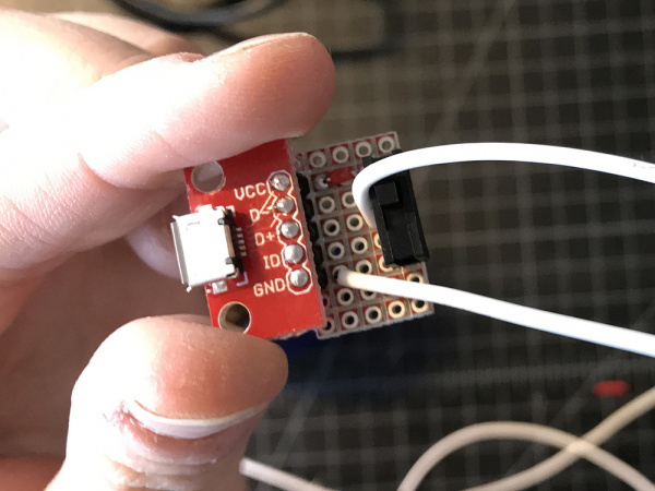
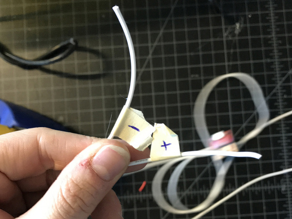
Solder one wire to GND of the USB breakout, and the other to the middle lead of the switch. Label these right away with masking tape. The GND wire should be ‘-’ and the Switch wire ‘+’.

Solder silicone wire

label wire

STEP 45:

Twist the silicone wires lightly, the solder the ‘+’ silicone lead to the Raw extension and the ‘-’ silicone lead to the GND extension.

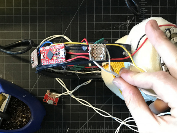
solder to extensions

STEP 46:

Plug the battery pack into the USB port and switch your project on to test. This is to make sure that the solder joints are strong and that there are no shorts.

STEP 47:

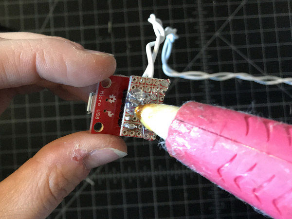
Add hot glue to the bottom of the protoboard for insulation.

insulate

Completing the Enclosure

STEP 48:

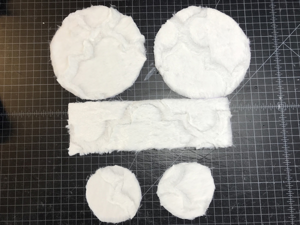
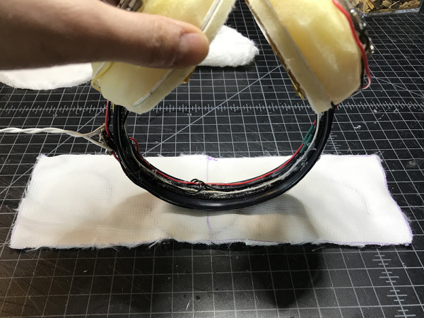
Grab both of the circles you cut from the template in Step 1. On the backside of your fabric, trace the large circle twice and the small circle twice. Then use a ruler to trace a 10.5" x 3.5" rectangle. Cut these out.

cut fabric

STEP 49:

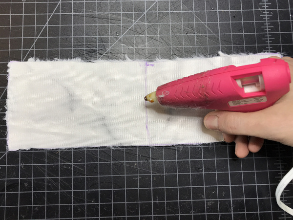
Find the center of the rectangle piece of fabric on the backside by folding it in half and marking it. Then add a small dab of hot glue.

mark center

STEP 50:

Place the top and center most point of your headband on top of the hot glue.

place headbandt

STEP 51:

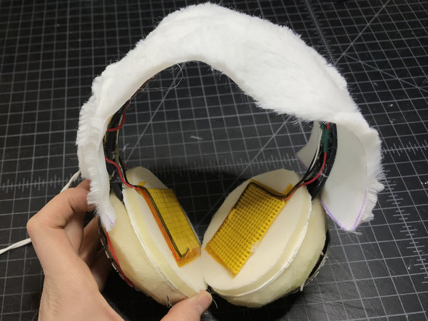
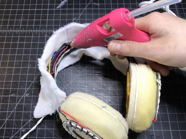
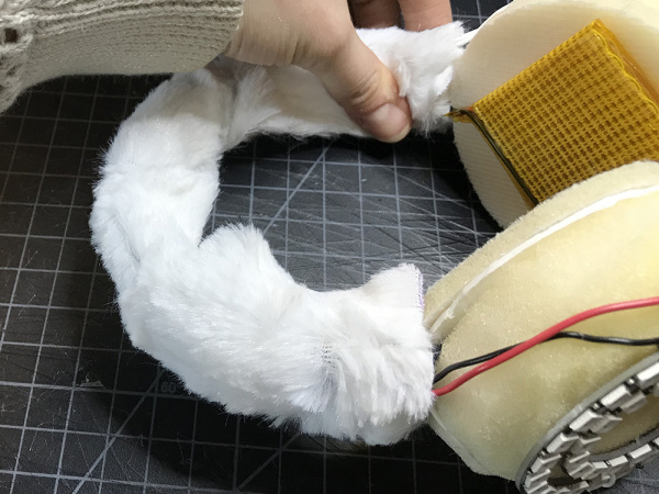
Continue to hot glue the fabric rectangle over the headband.

glue fabric

STEP 52:

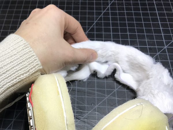
Add hot glue on the bottom side of the headband along one edge and fold the fabric over, beginning to cover the bottom of the headband.

glue bottom

fold fabric

STEP 53:

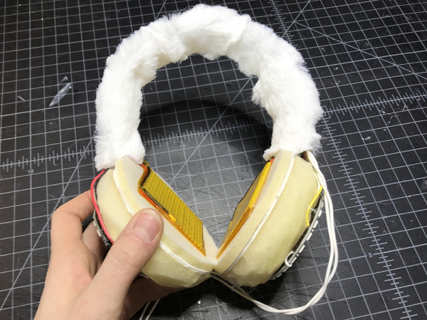
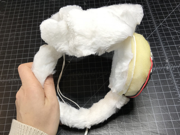
Add hot glue to the free edge of the fabric on the backside and fold this over too. Once completed, your headband should be completely wrapped by fabric.

fold over

wrap headband

STEP 54:

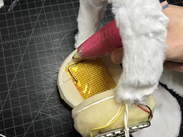
Add hot glue around the edge of the interfacing on one side, and place a small circle of fabric on top. Repeat on the second side.

hot glue interfacing

place small circle

STEP 55:

Add some hot glue to the center of one of your foam domes, and then drape one of the larger circles of fabric on top, placing it as centered as possible.

hot glue domes

drape large circle

STEP 56:

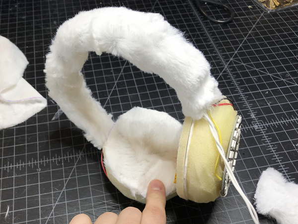
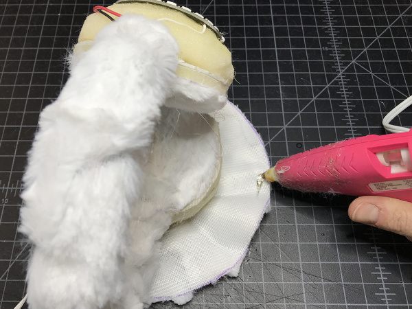
Add hot glue to the free edges of the larger circle and begin to wrap it around the dome until it is completely wrapped.

Glue edge of large circle

wrap around dome

STEP 57:

Plug in your power supply and turn the switch on!

plug in

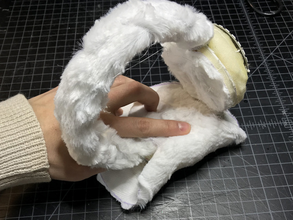
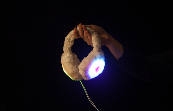
DIY Heated Earmuffs

Wearable DIY Heated Earmuffs

Resources and Going Further

Looking for another project? Check out these similar projects for inspiration!

Marquee Party Bag

This tutorial provides everything you need to know to make your own Marquee Party Bag!

DIY Light-Up Shoes

This tutorial provides everything you need to know to make your own light up high top sneakers!

learn.sparkfun.com |CC BY-SA 3.0 | SparkFun Electronics | Niwot, Colorado

Using the PSoC 6 Pioneer Board with the Pioneer IoT Add-on Shield

$
0
0

Using the PSoC 6 Pioneer Board with the Pioneer IoT Add-on Shield a learn.sparkfun.com tutorial

Available online at: http://sfe.io/t709

Introduction

The PSoC 6 is the latest addition to Cypress’s powerful PSoC series of processors. The PSoC 6 Pioneer IoT Add-On Shield is the development tool associated with this processor line, sporting an onboard debugger, Arduino compatible headers, CapSense widgets, and more, all tied to a PSoC 6 processor. The processor is a dual-core device, with a Cortex-M0+ low power processor and a Cortex-M4 high power processor tied together via shared peripherals and memory space.

Pioneer IoT Add-On Shield

DEV-14531
$19.95

This tutorial will show you how to get up and running with the Pioneer Board, using the Pioneer Add-on Shield to expand the capabilities of the PSoC 6 device. We’ll show you how to communicate with a Raspberry Pi via BLE and WiFi (using an XBee WiFi module), as well as how to communicate between a PSoC 4 BLE Pioneer Board and the PSoC 6 Pioneer Board via BLE.

Suggested Reading

There are a couple of tutorials that might be helpful to read before setting off on this one.

Raspberry gPIo

How to use either Python or C++ to drive the I/O lines on a Raspberry Pi.

Using Flask to Send Data to a Raspberry Pi

In this tutorial, we'll show you how to use the Flask framework for Python to send data from ESP8266 WiFi nodes to a Raspberry Pi over an internal WiFi network.

Required Materials

Obviously, you’ll need a Pioneer Add-on Shield. You’ll also need an XBee WiFi Module. There are a few XBee WiFi options depending on your setup: Trace, RP-SMA Connector w/ external 2.4GHz antenna, or Wire . The easiest would be to get XBee with the wire antenna.

XBee WiFi Module - Wire Antenna

WRL-12571
$43.95
Pioneer IoT Add-On Shield

DEV-14531
$19.95

You’ll also need the Raspberry Pi 3 Starter Kit. This will become your target for communication from the PSoC6 Pioneer Board. You can, of course, just purchase the Pi 3 separately along with a breadboard, jumper wires, resistors and LEDs, but we think the starter kit is an exceptional deal and is well worth getting.

Raspberry Pi 3 Starter Kit

KIT-13826
$89.95
37

Hardware Overview

Let’s go over the features of the Pioneer Kit IoT Add-on Board in detail.

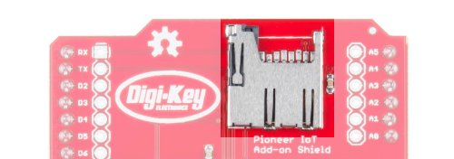
MicroSD Card Slot - The pins for this slot map to the SPI peripheral on most Arduino compatible boards, including the PSoC 6 BLE Pioneer Board.

Micro SD Card Slot

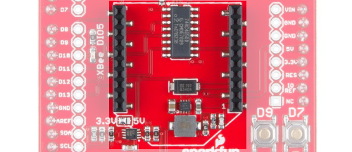
XBee Header - This header is spaced to accept the standard XBee footprint. It is compatible with all official XBee modules.

XBee Header

Qwiic Connector - This connector adds support for all of SparkFun’s Qwiic modules. It supplies 3.3V.

Qwiic Connector

MicroB USB Power Connector - Data lines on this connector are not connected to anything. It provides 5V to the 3.3V regulator for the XBee module, overriding the 5V coming from the Arduino header and allowing high power XBee modules (such as the cellular, wifi, or Pro models) to function properly.

MicroB USB Power Connector

D7 and D9 Buttons - Two user buttons tied to pins D7 and D9 (P0.2 and P13.1 on the PSoC 6, or P1.0 and P0.4 on PSoC 4 BLE).

Buttons

3.3V Regulator - Switch mode 3.3V power regulator capable of sourcing up to 1.5A, depending upon the upstream supply sourcing capacity. Draws power from 5V supply on Arduino pins or MicroB power connector. Supplies power to XBee header only.

Voltage regulator

Level Shift Buffer - Down converts from 5V signals to 3.3V signals. Allows board to be used in 3.3V or 5V systems.

Level shifter

I2C Level Shift Circuitry - Converts I2C signals from 3.3V to 5V, if necessary.

I2C Level Shifter

Voltage Supply Selection Jumper - Selects level to which I2C level shift circuitry translates. Default set to 3.3V. Set to 5V for use with 5V systems. Both the PSoC 4 and PSoC 6 Pioneer BLE boards are 3.3V systems.

Voltage supply jumper

XBee DIO5 LED - DIO5 defaults to some useful functions, especially on the WiFi module, where it shows connectivity to the configured WiFi network.

XBee DIO5 LED

Example: WiFi to Raspberry Pi Using the PSoC 6 Pioneer Kit

This example demonstrates how to send a signal to a Raspberry Pi via WiFi. It will show you how to access an XBee WiFi module, interprocess communication between the two cores of the PSoC 6, and how to receive and parse commands with a Raspberry Pi.

Following this example is going to require some setup, so let’s walk through that now.

PSoC 6 Pioneer Kit Setup: Hardware

The Pioneer Kit side setup is trivial: insert the XBee WiFi module into the Pioneer IoT Add-on Shield and insert the shield into the Pioneer Kit Board’s Arduino header.

The Raspberry Pi side requires more explanation. You’ll need to setup both some hardware and some software on the Raspberry Pi.

PSoC 6 Pioneer Kit Setup: Software

The software project for the Pioneer Kit is available on GitHub.

PSoc 6 Pioneer Kit Software Download

Once you have downloaded and extracted the file somewhere, you can open the example (XBee_WiFi_Example) in PSoC Creator.

Before you do anything else, you need to open the “main_cm4.c” file and make a couple of changes. You’ll find a section of code that looks like this:

language:c
char ssid[] = "your_ssid_here";
char rpi_ip[] = "raspi_ip_here";
char ssid_pw[] = "wifi_pw_here";
int dest_port = 5000;
char encrypt_mode = WPA2;

Hopefully, it’s obvious what you need to do: change these settings to match your network setup. The encrypt_mode value can be WPA, WEP, WPA2, or (hopefully not!) NO_SECURITY. rpi_ip is a dotted quad (e.g., “10.8.253.193”) that you can obtain from typing “ifconfig” in a command window on your Raspberry Pi (see below for instructions on opening a command window) and looking at the “wlan0” section.

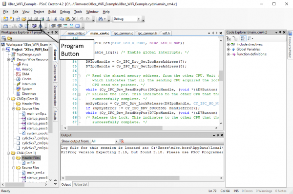
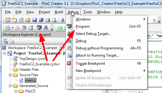
To program the board, connect it to your PC via the included USB-A to USB-C cable. Then, click the “Program” button in the toolbar (as shown below) to automatically build the project and program the board.

Program Button

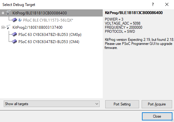
You may get a window as below asking you to choose a target to program. It does not matter which entry you choose under the “KitProg2” list item, either one will program the flash correctly.

Select debug target prompt

Raspberry Pi Setup: Hardware

First, let’s look at how the hardware is connected:

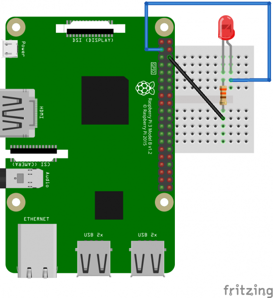
RasPi LED connection diagram

As you can see, we’ve connected an LED (with 330 ohm resistor) to pins 3 (GPIO 2) and 6 (ground) of the Raspberry Pi. This will allow us to toggle GPIO2 and see the result on the LED.

Raspberry Pi Setup: Software

We’re going to assume that you have a Raspberry Pi set up with the latest version of Raspbian (the full install, not the lite version) running, and that it’s connected to a keyboard, mouse, monitor, and local WiFi network. If this is not the case, please take a few moments to set this up. You can review our tutorial on setting up the Pi here.

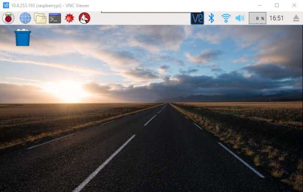
Let’s start from the desktop of the Raspberry Pi. You should have a screen up that looks something like this:

Pi desktop

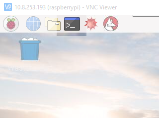
You’ll need to click the little logo at the top of the screen (shown below) to open a command line. The rest of this tutorial will assume that you have that command line open.

Command prompt

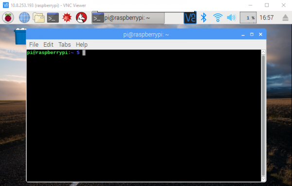
That will open a command line window. This allows you to tell the Raspberry Pi to directly execute commands.

Command prompt window

We’ll start by executing the command to install Flask. Flask is a web framework for Python that allows you to make a web front end that runs Python scripts on the sever backend fairly trivially. Type in the following command, then hit “Enter”.

sudo pip install flask

A whole bunch of stuff will happen in the command line window and at the end of it, Flask will be installed on your Raspberry Pi.

The next step is to install the software that we’ve written to support this project from GitHub. The command for doing that is

git clone https://github.com/sparkfun/Flask_Tutorial

Again, you’ll see some text scroll across the command line, and when the prompt returns, that’ll be your indication that the install process is complete. Once that’s complete, enter this command:

sudo python Flask_Tutorial/Python/app.py

That will launch the app and begin listening for input over TCP/IP from the Pioneer board. You should now be able to turn the LED connected to the Raspberry Pi on and off by pressing the D7 and D9 buttons on the IoT Shield. Neat!

So What’s Going On Here? Pt. 1: The Pioneer Kit

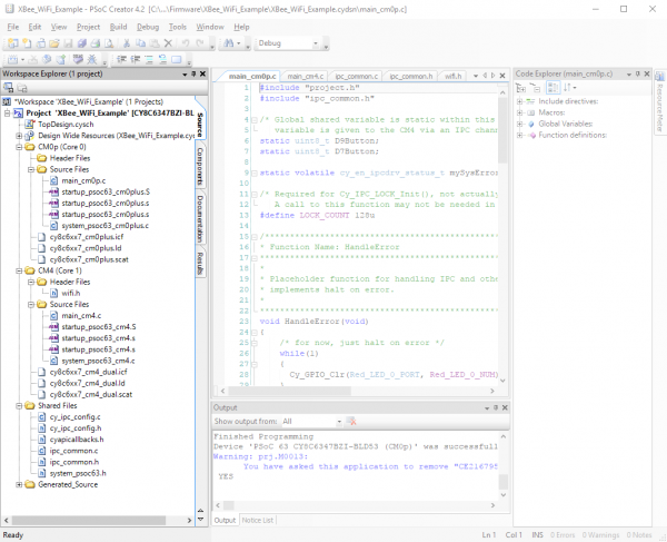
Let’s take a look at what exactly is happening, starting from a high level view of the PSoC 6 software project. Look at the Workspace Explorer frame on the left hand side of the screen. We’ll walk through that frame, highlighting the files of importance and how they relate to the overall project.

Workspace explorer

Having a hard time seeing the Workspace Explorer? Click the image for a closer look.

The top level of the project has six entries: the schematic (“TopDesign.sch”), the Design Wide Resources (“XBee_WiFi_Example.cydwr”), the source files associated with the Cortex-M0+ core (“CM0p (Core 0)”), the source files associated with the Cortex-M4 core (“CM4 (Core 1)”), files to be shared between the two (“Shared Files”), and support files generated by the IDE (“Generated_Source”).

The schematic for this project is very simple, having a couple of LEDs, a couple of switches, and the UART used to transfer data to and from the XBee WiFi module. The LEDs are actually unused in the current implementation of the project.

Schematic

We’re going to skip over the contents of the .cydwr file. This file contains the pin assignments for the signals used in the schematic, the clock generation, and core configuration constants. If you want to investigate it more, feel free to dig in a little bit. Much of it should be self-explanatory.

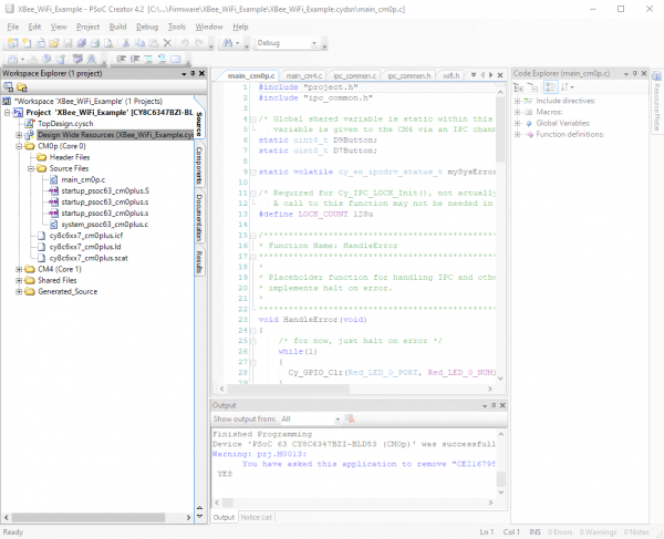
Moving on down the list, we reach our Cortex-M0+ source files. You’ll note that the top level in this subdomain has five entries: “Header Files”, “Source Files”, and three other files. We only need concern ourselves with the contents of the “Header Files” and “Source Files” subdomains, and in fact, only with one file in those: the “main_cm0p.c” file. This is where the main() function for the code which runs on the Cortex-M0+ processor lives.

Cortex-M0+ files

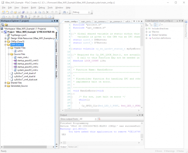
As you may have guessed from the structure of the workspace, there are two entirely separate codebases running for the two different cores. “main_cm0p.c” is the entry point for the Cortex-M0+ core’s code, and then that core starts the Cortex-M4 core. There exists a similar subdomain for the Cortex-M4 core with similar files and again, we only need to worry about the “Header Files” and “Source Files” subdomains.

Cortex-M4 files

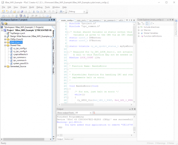
Finally, we have the “Shared Files” section. Most of these files are automatically generated, save the “ipc_common.c” and “ipc_common.h” files. These files are helpers for interprocess communication developed for this project.

Shared files

The Cortex-M0+ Main File

Now that we’ve highlighted the important contents, let’s take a look at the important bits of the code, one file at a time, starting with the “main_cm0p.c” file. This file handles all the activity that the Cortex-M0+ core does for the system: monitoring the two pushbuttons and sending a signal to the Cortex-M4 when one or the other of them is pressed.

However, this is not as straightforward as it seems, as the Cortex-M4 needs to be able to clear the signal once it has dealt with it, and that means multiple processes accessing the same data. Any time you have multiple processes working on the same dataset, you need to consider the effects of a write collision. What happens if one process attempts to change the data in the middle of the other process trying to change the same data? To deal with this we use a system protected reads and writes, set up in the “ipc_common” files.

To understand how this works, one must first understand the concept of an IPC channel. IPC channels use semaphores to write data from one process to another while guaranteeing that there will be no collision between the two core. At the beginning of application execution for each core you must establish endpoints for the IPC channels to be used during execution. Consider these two lines of code:

language:c
IPC_STRUCT_Type *D9IpcHandle;
D9IpcHandle = Cy_IPC_Drv_GetIpcBaseAddress(7);

The first creates a pointer for a struct which defines the characteristics of an IPC channel. The second actually sets that struct to point to a specific memory location, that of system IPC channel 7. We use channel 7 because channels 0-6 are reserved for system use.

Next we must, of course, tell the other core which memory address is associated with this IPC channel. That is what this function call does.

language:c
while(Cy_IPC_Drv_SendMsgPtr(D9IpcHandle, CY_IPC_NO_NOTIFICATION, &D9Button) != CY_IPC_DRV_SUCCESS);

D9Button is a variable set up earlier in the code. The function call is enclosed in a while() loop because we want to repeat the function call until we receive verification that the other process (i.e., the code running on the Cortex-M4 core) has received this information. We also want to wait until the lock on the variable is released, indicating that the Cortex-M4 has finished reading the pointer value.

language:c
while(Cy_IPC_Drv_IsLockAcquired(D9IpcHandle));

Finally, we drop into our infinite loop for the application, where the custom functions ReadSharedVar() and WriteSharedVar() handle updating the shared variables which communicate button status with the other core. We’ll delve into those functions later.

The Cortex-M4 Main File

In the Cortex-M4 main() function, we repeat some of the same operations as we did in the Cortex-M0+ main() function vis-a-vis setting up of the IPC channel.

language:c
IPC_STRUCT_Type *D9IpcHandle;
D9IpcHandle = Cy_IPC_Drv_GetIpcBaseAddress(7);

Once that’s completed we must then call some code to “catch” the message that was sent from the Cortex-M0+ process, containing the address of the shared variable to be accessed.

language:c
while (Cy_IPC_Drv_ReadMsgPtr(D9IpcHandle, (void *)&D9Button) != CY_IPC_DRV_SUCCESS);

Again, we enclose this call in a while() loop so that it gets continually called until the message is sent from the Cortex-M0+. Then we must release the lock on that IPC channel so that the Cortex-M0+ process knows that it can continue operation and use the IPC channel in the future. There is no need to enclose this in a while() loop because it is open ended: the call only needs to be issued once to release the lock, versus checking that the lock has been released, which must be repeated until such time as the lock is released.

language:c
Cy_IPC_Drv_LockRelease(D9IpcHandle, CY_IPC_NO_NOTIFICATION);

Once all of this has been completed, we must set up the XBee WiFi shield to access our local network. We won’t duplicate all that code here, as it’s well documented in the example.

In the infinite loop that runs the application code, we again call the custom functions ReadSharedVar() and WriteSharedVar() to access the variables holding the button status, which are shared with the Cortex-M0+ core. Let’s take a closer look at what these functions do.

The “ipc_common.c” File

As mentioned earlier, we must use a semaphore protected variable to communicate between the two processes currently running on the PSoC6. By protecting our reads and writes with a semaphore we ensure that there will be no collisions of access to those variables.

We’ll look at the WriteSharedVar() function first. It accepts as parameters a pointer to a shared variable, a value to be written into that shared variable, and a semaphore number to use for protecting this transaction. It is important that both processes use the same semaphore to protect any variable which is written this way; in “ipc_common.h” there is a define for semaphores to be used for each of the two variables to be shared between the processes. There are 128 semaphores available to the application, but the semaphores 0-15 are used behind the scenes, so user semaphores must be number 16 or higher.

This first section of code handles setting the semaphore. It is set to timeout in 1000 microseconds. This is important because we don’t want to idle excessively waiting for the other process to release the semaphore.

language:c
for (timeout = 0ul; timeout < MY_TIMEOUT; timeout++)
{
    rtnVal = (uint32_t)Cy_IPC_Sema_Set(semaID, false);
    /* exit the timeout wait if semaphore successfully set or error */
    if ((rtnVal == (uint32_t)CY_IPC_SEMA_SUCCESS) || IsSemaError(rtnVal))
    {
        break;
    }
    CyDelayUs(1);
}
if (timeout >= MY_TIMEOUT) rtnVal = CY_RET_TIMEOUT;

This second section of code handles writing the shared variable and releasing the semaphore. Again, clearing the semaphore is done within a timeout loop.

language:c
if (rtnVal == CY_IPC_SEMA_SUCCESS)
{
    *sharedVar = value;

    /* timeout wait to clear semaphore */
    for (timeout = 0ul; timeout < MY_TIMEOUT; timeout++)
    {
        rtnVal = (uint32_t)Cy_IPC_Sema_Clear(semaID, false);
        /* exit the timeout wait if semaphore successfully cleared or error */
        if ((rtnVal == (uint32_t)CY_IPC_SEMA_SUCCESS) || IsSemaError(rtnVal))
        {
            break;
        }
        CyDelayUs(1);
    }
    if (timeout >= MY_TIMEOUT) rtnVal = CY_RET_TIMEOUT;
}

Now let’s look at the ReadSharedVariable() function. In this case, we’re passing a const pointer to the variable, a pointer to the copy, and the semaphore number. The code is identical to the WriteSharedVariable() function except for the actual access to the variable:

language:c
*copy = *sharedVar;

As you can see, this time we’re setting our copy to the value of the shared variable. Not surprising considering the point of this function is to move the shared variable into a local copy for the process to work on!

What’s Going on Pt. 2: The Raspberry Pi

Let’s look at the code on the Raspberry Pi. It’s pretty simple!

language:python
from flask import Flask
import RPi.GPIO as GPIO

These are your general import statements. We installed Flask earlier, and the RPi.GPIO module comes installed on the Raspberry Pi already. Next we get into setting up our GPIO:

language:python
GPIO.setmode(GPIO.BCM)  # Sets up the RPi lib to use the Broadcom pin mappings
                        #  for the pin names. This corresponds to the pin names
                        #  given in most documentation of the Pi header
GPIO.setwarnings(False) # Turn off warnings that may crop up if you have the
                        #  GPIO pins exported for use via command line
GPIO.setup(2, GPIO.OUT) # Set GPIO2 as an output

This section should be fairly understandable via the comments. Then we have to set up our Flask app:

language:python
app = Flask(__name__)   # Create an instance of flask called "app"

We’ll now refer back to that Flask app for our route handling functions. Flask behaves a lot like a standard webserver, serving up pages in response to http requests against a certain path, except instead of serving a page it executes a chunk of python code. The default route handler (i.e., when no route is given in the http request) is thus:

language:python
@app.route("/")         # This is our default handler, if no path is given
def index():
    return "hello"

The result, should you visit this in a web browser, is a simple page reading “hello” in plain text. The real magic happens when you visit a more highly defined path:

language:python
@app.route('/gpio/<string:id>/<string:level>')
def setPinLevel(id, level):
    GPIO.output(int(id), int(level))
    return "OK"

In this case, when you send the path “/gpio/2/1”, the Flask app interprets that to be a GPIO number (we’ve only enabled GPIO 2) followed by a level to set the GPIO to (1 or 0). The last thing we need to do is provide the system with some insight into how to run the app:

language:python
if __name__ == "__main__":
    app.run(host='0.0.0.0', port=5000)

This code specifies that the app should be run locally, visible to the outside world, on port 5000. I recommend leaving it as it is, but you can change the port number if you really want to (and really know what you’re doing).

Example : BLE to Raspberry Pi Using the PSoC 6 Pioneer Kit

This example shows how to send a simple signal via BLE to the Raspberry Pi. It uses only the Cortex-M0+ core, running a Cypress provided code example.

Programming the PSoC 6 Pioneer Kit

If you followed our first example, you should be familiar with how to program the PSoC 6 Pioneer Kit board with a new firmware. Repeat this process with the workspace named “BLE_To_RPi”. This is just a renamed copy of Cypress code example CE218134.

Programming the Raspberry Pi

Programming the Raspberry Pi is fairly easy. You don’t need to install any additional software, just download the repository from GitHub with the following command:

git clone https://github.com/sparkfun/Pioneer_Kit_Shield

Then, run the python program which will listen for BLE communications by entering this command:

sudo python Pioneer_Kit_Shield/Software/BLE/scanble.py

That should be all it takes. You’ll now be able to toggle the LED on the Raspberry Pi using the two CapSense buttons on the PSoC6 Pioneer Kit board.

What’s Going On Here Pt. 1: PSoC 6

I’m not going to delve too deeply into the PSoC 6 code, as it’s very well documented in the example. I’ll call attention to a few details, however.

First, this code runs entirely on the Cortex-M0+ processor core. The other core is never activated.

Second, CapSense events are sent as notifications, which means they are sent from the server (the PSoC 6 board) to the client (the Raspberry Pi). The Raspberry Pi doesn’t need to request data from the server as it will be automatically updated on change.

Third, the Raspberry Pi app is hardcoded to attach to the PSoC 6 app. If you’re in an environment where there are multiple PSoC 6 boards, you’ll have to change the public address of the BLE app as well as the address being looked for in the Python app.

What’s Going On Here Pt. 2: Python and Raspberry Pi

The Python code uses the Bluepy module, which should be installed on your Raspberry Pi by default.

We’re going to take this one a little out of order, so the code makes more sense. We start by creating a Peripheral object, passing it a string of hexadecimal values corresponding to the public address of the BLE device we’re looking for.

language:python
device = Peripheral("00:A0:50:21:81:34")

We then create and assign the ScanDelegate class object to that peripheral device. This lets the module know that this is the object to which incoming BLE messages should be assigned. This will block for approximately 30 seconds waiting for a connection to the Peripheral object we assigned it to.

language:python
device.withDelegate(ScanDelegate())

We now need to write two characteristics: one to start messages flowing from the CapSense buttons and one to turn the onboard LED white as a sign that the connection was successful.

language:python
device.writeCharacteristic(29, b"\x01\x00", withResponse=True)
device.writeCharacteristic(23, b"\xff\xff\xff\xff", withResponse=True)

Now let’s go back up in the code and look at the ScanDelegate class. I’ve removed the trivial code which senses the button state and makes sure that only one button press at a time is recorded no matter how long the buttons are held down.

language:python
class ScanDelegate(DefaultDelegate):
    def __init__(self):
    DefaultDelegate.__init__(self)

    def handleNotification(self, cHandle, data):
        ## Do something with the data object

data will be an array containing all of the bytes sent by the Bluetooth server. In this case, it’s two bytes, the second of which tells us which button is pressed.

Finally, at the bottom of the code, we have this section, which waits for notifications in one second blocks and is interrupted by a call to handleNotification() when one is received:

language:Python
while True:
    if device.waitForNotifications(1.0):
        continue

And that’s how easy it is to receive data from a BLE device via Python on a Raspberry Pi. All told, less than 50 lines of code.

Resources and Going Further

Now that you’ve successfully got your PSoC 6 Pioneer Board and Pioneer IoT Add-on Shield up and running, it’s time to incorporate it into your own project!

For more information related to the PSoC 6 Pioneer Board and Pioneer IoT Add-on Shield, check out the links below:

Need some inspiration for your next project? Check out some of these related tutorials:

Are You Okay? Widget

Use an Electric Imp and accelerometer to create an "Are You OK" widget. A cozy piece of technology your friend or loved one can nudge to let you know they're OK from half-a-world away.

ESP8266 Powered Propane Poofer

Learn how Nick Poole built a WiFi controlled fire-cannon using the ESP8266 Thing Dev Board!

Blynk Board Bridge Widget Demo

A Blynk project that demonstrates how to use the Bridge widget to get two (or more) Blynk Boards to communicate.

Connectivity of the Internet of Things

An overview of the different protocols that can be used for the development of Internet of Things (IoT)-based projects.

learn.sparkfun.com |CC BY-SA 3.0 | SparkFun Electronics | Niwot, Colorado

Prototype Wearable LED Dance Harness

$
0
0

Prototype Wearable LED Dance Harness a learn.sparkfun.com tutorial

Available online at: http://sfe.io/t464

Introduction

Have you ever wanted to merge technology with your dance? In this tutorial, you will learn how to design and build a wearable LED harness for dance performances. The design is not just limited to dance. You can also use it as a guide for costumes.

Dress Rehearsal with LED Straps

Required Materials

To follow along with this tutorial, you will need the following materials. You may not need everything though depending on what you have. Add it to your cart, read through the guide, and adjust the cart as necessary.

  • Electrical Tape
  • 12 Gauge Clear Vinyl
  • ⅞“ Yellow Ribbon
  • 1 ½“ Yellow Ribbon
  • Adhesive Velcro
  • Thread
  • Twine or Any Toothy String
  • Translucent Yellow Button Up Shirt
  • Bow Tie (Optional)
  • Folded Handkerchief (Optional)

Tools

You will need a soldering iron, solder, general soldering accessories, and tools to work with wire.

Hakko FX888D Soldering Station

TOL-11704
$99.95
50
Solder Lead Free - 100-gram Spool

TOL-09325
$7.95
7
Wire Strippers - 30AWG (Hakko)

TOL-12630
$9.95
3
Diagonal Cutters

TOL-08794
$1.95
2

You will also need:

  • Scissors
  • Cutting Board
  • Rotary Cutter
  • Lighter
  • Needle
  • Sewing Machine
  • Measuring Tape
  • Yard Stick

Suggested Reading

If you aren’t familiar with the following concepts, we recommend checking out these tutorials before continuing.

How to Power a Project

A tutorial to help figure out the power requirements of your project.

Planning a Wearable Electronics Project

Tips and tricks for brainstorming and creating a wearables project.

Design

Designing wearable electronics around a dancer is difficult depending on the movement. As a bboy, just about every part of the body is used on the floor.

Bboy Holding a Chair Freeze

So when planning for a show using wearable electronics, it needs to be:

  • Flexible
  • Durable
  • Secure
  • Quick to Connect
  • Safe
  • Light Up Throughout the Performance

On top of that, I needed to make enough for each student in my troupe. I decided make a harness to hold the electronics based on a backpack's shoulder straps. A button up shirt was used to diffuse the light. A bowtie and pocket square were added for detail.

For the scope of the tutorial, I'll be focusing on the harness to hold the LEDs and the electronics.

Electroluminescence (EL) vs Light Emitting Diode (LED)?

I debated with using either EL wire or LEDs. Each have different uses depending on the performance and lighting of the environment.

With the first wearable design for dance, I found that EL was harder to see with ambient lighting even with EL tape and panel. I was also limited to one color at a time. However, it required less power and it did have a different affect. For the second design, the LEDs were easier to see with the ambient light and I was able to select more than one color. The LEDs did require a little bit more power.

Mark I: EL Dance ShirtMark II: LED Dance Harness

Understanding Your Circuit

The circuit for the wearable LED harness is simple. Let's take a look at the left side of the harness that holds the battery, adapters, and LEDs.

Initial Circuit

Power is connected to the “+12V” pad of the non-addressable LED strip. To complete the circuit and power the LEDs, ground is connected to each color’s pad labeled “G,” “R”, or “B.” Green and blue were chosen to make cyan from the primary colors. For one side of the harness, LED segment A consisted of a long strip of 33x LEDs. LED segment B and C consisted of 3x LEDs each.

Fritzing Diagram Wearable LED Harness Circuit

Having a hard time seeing the circuit? Click the image for a closer look.

A 9V battery and custom made adapters were used for each harness. Keep in mind that a 9V battery is not able to power all three colors simultaneously. However, using two colors was sufficient enough for the project and performance.

Complete Circuit

The connection was then wired in parallel on the other side of the harness by connecting to the same rails on the solderable breadboard.

Fritzing Diagram Wearable LED Harness Fill Circuit

Having a hard time seeing the circuit? Click the image for a closer look.

Stitching It Together

From the image shown below, prepare the fabric based on the user’s height by cutting the ribbons and transparent vinyl. Carefully heat the ribbon ends with lighter to prevent the ends from unraveling. Listed below are the average lengths used for a kid.

  • 2x Transparent Vinyl - 25"
  • 4x Transparent Vinyl - 3"
  • 2x 0.5" Ribbon A (for the top) - 25"
  • 2x 1.0" Ribbon B (for the back) - 9"
  • 4x 0.5" Ribbon C (for the front ribbon ties) - 15"
  • 4x 0.5" Ribbon D (for the bottom) - 5"

Prepare the Harness

Pin down the bottom of the harness and sew the ends together in a square pattern with a needle and thread.

Sew Bottom of the Harness

Pin and sew the bottom of the harness with the longer piece of ribbon. Make sure to sew the end in a triangular or square pattern to secure the ribbon.

Sew Top of Harness

Make sure that the ribbon is flat and facing the same direction when sewing the top and bottom together. They should be free from any twists.

Left and Right Harness

Starting with the right side of the harness, pin and sew the ribbon ties for the sternum and waist. The ribbon tie for the chest was about 10 inches above the waist. The ribbon tie for the waist was added to the bottom of the long strip. Repeat for the left side. Choosing one side of the harness, attatch the back ribbons using the same 10 inch spacing as the ribbon ties.

Sew the Ribbon Ties and the Back

At this time, sew the opposite side to the harness. Using pins and a sewing machine, sew clear vinyl to the inside of the ribbon to the top and bottom each side. The vinyl should wrap around the LEDs and end behind the LEDs.

Attach Both Sides to the Harness and Sew the Vinyl Together

The completed harness should look like the image below.

Completed Wearable LED Harness

Hardware Hookup

Connecting LED Strip Segments

Cut the LED strip at the center of the exposed pads using a diagonal cutter. The dot and dashed line in the image below is where you will need to perform the cut. Make sure to remove part of the silicone tube in order to be able to access the LED Strip’s pads.

Cut between the LED Strip's Pads

Cut half of the 12" premium jumper wires and strip the insulation. Then solder the wires to each of the LED strip’s pads.

Solder Wires to LED Strip

The connection to the pads needed to be secure so I decided to braid the wires together to manage the connections. I was inspired by McCall’s tutorial when completing projects. To braid your wires, twist a pair of wires in a counterclockwise pattern between your index finger and thumb using both hands. I decided to start with the green and red wires.

Wire Management Braiding Counterclockwise 1

Twist the other pair of wires in a counterclockwise pattern.

Wire Management Braiding Counterclockwise 2

Twist the pairs of wires in a clockwise pattern.

Wire Management Braiding Clockwise

Repeat for segment B and C. The segments will be using shorter wire.

Clean Solder Joints

If you were using water soluble flux, clean the solder joints with de-ionized water and a toothbrush. Dry the LED strips thoroughly using compressed air. Luckily, SparkFun has a PCB cleaning room. As an alternative, you could use water from the sink and towels.

Clean Solder Joints

Test LED Strips

Once dry, test the LED strips to make the colors matched and the wires are connected to its respective pads. I decided to use a benchtop power supply set to output about 9V to verify the connection.

Testing LED Strips

Secure w/ Hot Glue

Add hot glue to the terminals to secure the wires further.

Hot Glue Terminals

Custom Power Adapter w/ Solderable Breadboard

Using a dremel and Panavise, carefully cut the solderable breadboard in half.

Cut Solderable Breadboard in Half

Solder the female barrel jack connector to the board so that the connector is flush with the edge.

Solder the Female Barrel Jack

Cut the 1x4 pin jumper wire in half and strip each wire using 0.1" spacing. Solder the wires as illustrated earlier in the Fritzing diagram.

Solder each 1x4 jumper wire

Solder the GND pins together for two of the colors with a solder bridge. Then connect it back to the barrel jack connector an extra wire to the sheath.

Connect GND

Solder the center pin to the “+12V” pin.

Connect Center Positive to +12V

Clean, dry, and test the board with a multimeter, power supply, and the LED strips. Feel free to label the connections with a marker or paint.

Complated Custom Power Adapter

Finally, secure the wires and insulate the connection using hot glue just like the LED strip.

Secure Wires

Secure all the jumper wires with electrical tape.

Electrical Tape

Place the LED strip between the ribbon and vinyl. Make sure to have the LEDs facing out of the clear vinyl. Attach adhesive velcro as highlighted in the image below to hold LED strip down.

Velcro

Add extra M/F premium jumper wires to extend the LED strip on one side to the breadboard power adapter on the other side. To be consistent I chose to attach the battery and custom adapter on the dancer's left side.

Wire Extensions

Tie the wires extended on the back and the custom power adapter with string.

Tie down

The user can then slide the harness on like a backpack, tie the ribbons across the chest and waist, and plug in the battery to test.

Wearable LED Harness

Repeat

Once the first wearable LED dance harness was finished, I repeated the steps until there was enough for each dancer in the troupe. I built a total of 7x units for my students. This required a lot of time and patience.

Over the course of about 2-3 months and balancing my usual work schedule, I was able to finish the project!

Completed Wearable LED Harnesses Illuminating Shirts

Stress Testing In the Field

Benchtop Tests

Before the rehearsals and performances, I tested the harnesses out under the fabric using a benchtop power supply for about 60 minutes. I then tested it in a studio with the choreography using 9V batteries.

LED Dance Costume Harness Testing

Dress Rehearsal

When the time came, my students were excited to test it out for the dress rehearsal. This was a good time to explain how to tie the harness, put on the shirt, and power the LEDs with the barrel jack underneath the button up.

Dress Rehearsal

The LED harnesses lasted throughout the dress rehearsal even though they were upside down, side ways, or moving across the floor. There did not appear to be any damage to the circuit. After about an hour, the 9V battery still had power for the show!

Show Time!

When it came time for the show, I had my handy multimeter, scissors, electrical tape, and backup 9V batteries just in case I needed to troubleshoot. However, everything seemed fine. Here’s a picture of them backstage right before going on.

Backstage

In the end, the performance (which lasted ~1:30-2:00 minutes) ran smoothly without the LED harnesses “breaking” on my bboys. Whew, that was a lot of work!

Making It Better

There’s always room for improvement. After the project was completed, I realized that the harness could be built better. Below are a list of possible upgrades and improvements that could be implemented for future builds.

  • Vest - It was exhausting making about 10-15x units for each student. In the future, I may just consider buying a vest/harness and adding the parts to the material to save on time and energy.

  • Connectors - The 1x4 female header pins were tedious to strip and solder each wire to the breadboard. Using individual jumper wires would have been easier to connect.

    I also noticed that a male header pin broke off one of my student’s harness after about 1 year due to wear and tear. It might be better to use female headers for all the connections, extra long header pins between the housing, and secure the connection with electrical tape.

  • Quick Release Buckle vs Ribbon Ties - A few of the students had some issues tying the ribbon. Instead of using ribbon ties, a quick release buckle could make it easier

  • Snaps vs Velcro - The velcro held the LEDs and the vinyl securely. As an alternative, a button tool and metal snap could be used.

  • Labels - Initially, I did not label the wire colors. After a few months, I forgot about the wire connections on the LED strips, jumper wires, and custom power adapter. I decided to try and revise the project by adding sensors to control the LED straps. It was not until I inspected the connection throughout the harness again that I remembered the simple circuit. Labeling the connection with a marker or paint would have saved some time.

  • Switch - Plugging in the battery underneath the button up shirt was a little difficult even with the barrel jack. Adding a latching switch after the battery would improve on the design.

  • Pocket for 9V Battery - With the amount of time I had available, I decided to just tape the battery and cable to the harness and the ribbon tie. A pocket to hold the 9V battery would make it easier to switch out.

  • Sensors to Control - For Mark III, I decided to add a sensor to the wearable LED dance harness. I used the full mini-solderable breadboard and microcontroller. More on the details next time!

Resources and Going Further

Need some inspiration for your next e-textiles project? Check out some of these related tutorials:

Hackers in Residence - Sound and Motion Reactivity for Wearables

How to consciously wear light-up and and sound reactive clothing.

EL Wire Light-Up Dog Harness

Learn how to create a light-up dog harness using EL wire for when you need to take your four-legged friend for a walk in the dark.

Sound Reactive EL Wire Costume

Learn how to make your EL wire costumes sound reactive in this project tutorial.

Pokémon Go Patches with EL Panels

Add a cloth stencil over EL panels to create glowing logos and designs.

Or maybe check out these wearable designs from other SparkFunions!


learn.sparkfun.com |CC BY-SA 3.0 | SparkFun Electronics | Niwot, Colorado

FreeSoC2 Hookup Guide V14

$
0
0

FreeSoC2 Hookup Guide V14 a learn.sparkfun.com tutorial

Available online at: http://sfe.io/t556

Introduction


The FreeSoc2 is SparkFun’s PSoC5LP development board features a full onboard debugger, support for 5V and 3.3V IO voltages, and a CY8C5888AXI-LP096 processor with 256kB of flash, 64kB of SRAM and 2kB of EEPROM. The onboard oscillator can drive the processor at up to 80MHz, and the Cortex-M3 core provides superior performance.

FreeSoC2 Development Board - PSoC5LP

DEV-13714
$49.95

The real power of the PSoC5LP isn’t in the processor, however. Wrapped around the processor is a rich analog and digital programmable fabric, which can be configured to provide many functions that would otherwise need to be realized in code (lowering system performance) or external circuitry (adding cost and board size). In addition, the highly flexible fabric means that most any function can be routed to most any pin, which makes this a wonderful tool for development and allows board layout errors to be solved, at least temporarily, pretty easily. Conceptually, this fabric is similar to an FPGA or CPLD.

Covered in This Tutorial

We’re going to discuss two different ways to tap the power of the PSoC. We’ve ported the Arduino core to the PSoC5LP, so you can write code for the board in the standard Arduino IDE. The board duplicates the functionality of an Arduino Uno R3’s various hardware peripherals on the pins, so many examples, libraries, and shields will work out of the box.

The drawback of using the Arduino IDE, however, is that it lacks any means of configuring the programmable fabric (at the moment, at least). To get the most out of the device, you’ll need to use the PSoC Creator IDE, which is free of charge with no code limits from Cypress Semiconductor. Sadly, the PSoC Creator software is Windows-only at this time. If you want to see that change, consider piping up on the Cypress forums!

In this tutorial, we’re going to go over the detailed specifications and layout of the board, how to add support for the board to the Arduino IDE, and how to get started with a simple blink project on the PSoC Creator IDE.

Required Materials

We’re going to keep it simple; the FreeSoC2 has an onboard LED and user-accessible pushbutton. We’ll use those for our lessons. That means you’ll only need the FreeSoC2 board and a micro-B USB cable. You may, however, find it useful to have a second USB cable, as that will allow you to connect to both the debugger and the target at the same time.

Suggested Reading

If you’re unfamiliar with the Arduino IDE, but want to learn, check out our tutorial on installing the Arduino IDE.

As with any development platform, it’s always wise to read the datasheet. Check out the datasheet for the PSoC5LP CY8C58LP before continuing.

Hardware Overview

There’s a lot going on on this board: two processors, two USB ports, a ton of headers, and all sorts of configurable options.

Left half

We’ll take a hardware tour, one element at a time, starting with the debugging and connection elements on the left.

  1. 5.5mm x 2.1mm center positive barrel jack – This fits all of SparkFun’s standard “wall wart” type power supplies. While the regulators on the FreeSoC2 can handle input voltages up to 12V, it’s best to keep the input voltage as close to 5V as possible.
  2. “Target” USB Port – Provides USB connectivity to the target processor (the CY8C5888). When uploading code via the Arduino IDE, you’ll connect to this port.
  3. “Debugger” USB Port – Connects to the debugger IC. Connecting to this port also creates a USB serial port that can be used to get and send data from and to a UART on the target processor.
  4. 2.5mm JST PH series connector footprint – Our through hole 2-pin JST PH connector fits here, allowing you to power the board with any of our standard lithium ion polymer batteries.
  5. Debugger reset button – Resets the debugger. You will probably never need to use this.
  6. Debugger user button – Can be used to provide input to the debugger IC; currently unused.
  7. IO voltage selection switches – These switches allow you to select the voltage of the I/O signals, either 3.3V or 5V, on the target processor. The PSoC5LP has four I/O voltage quadrants; the bottom switch allows you to select the voltage of the quadrant providing the Arduino header signals, and the top switch controls all the others.
  8. Debugger IC JTAG/SWD header – This 2x5 0.050" pitch header can be used to program and debug the debugger itself. It’s intended to support a connection to the MiniProg3 programmer/debugger from Cypress. You’ll probably never need to use it.
  9. Target IC JTAG/SWD header – Similar in nature to the header for the debugger; the signals on these pins also come from the debugger IC.
  10. Debugger IC – The debug IC is also a PSoC5LP- in this case, CY8C5868LTI-LP039. The firmware it comes preloaded with (referred to as “KitProg”) is freely available for download and modification; the part is bootloadable to replace the firmware or update it as new firmware becomes available.
  11. Debugger IC IO header – There are a number of signals available on this header; they are not used by default but you may implement additional debugging features on the debugger IC that do use them.
  12. Debugger IC user LED – Will be lit if the debugger can’t detect a host, and will flash during data transfer (i.e., programming or debugging).
  13. I2C isolation jumpers – These normally open solder jumpers allow you to connect the I2C lines on the target board with the debugger. Using Cypress’s KitProg debugging software, you can snoop the I2C data traffic from the target IC. Normally, these are open, disabling this capability. Close them with solder blobs to connect the debugger to the target’s I2C bus.
  14. Battery Supply Diode Bypass – If you populate the 2.5mm JST connector and run the FreeSoC2 off of a LiPo battery, you may find the ~0.5V drop across the diode which ORs the battery supply into the main supply rail. This jumper may be closed with a blob of solder to bypass that diode.

    Caution: if you close this jumper but fail to open the “BATT ISOLATE” jumper (item 15), plugging the board into USB power may cause damage to your battery or even a fire as the 5V USB supply shorts to the LiPo battery output.
  15. Battery Isolate jumper – Whenever you close the “D BYPASS” jumper (item 14), this jumper must be opened, to avoid risk of damage to the battery or fire.

Right half

The right half of the board contains the target IC (a CY8C5888AXI-LP096) and the associated headers.

  1. Arduino Uno R3-type headers – For the most part, these headers are completely compatible with the Uno R3 board. The only exception is the VREF pin, normally located between the I2C pins and the ground above D13, is no-connect for this board.
  2. Target user LED – Tied to port 6, pin 7, which corresponds to D13 on the Arduino mapped headers.
  3. ADC reference bypass capacitor jumpers – These jumpers allow you to add a 100nF capacitor to three of the PSoC part’s pins, to provide a bypass for ADC voltage references to increase the reference’s accuracy.
  4. High-frequency crystal footprint – if you need better accuracy than can be achieved by the onboard oscillator, you may add a standard HC/49 crystal here.
  5. Low-frequency crystal fooprint – if you want to implement an RTC, you may add a 32.768kHz clock crystal here.
  6. Target IC reset button – This button resets only the target IC.
  7. Target IC user button – This button can be mapped to any purpose within the application; the button pulls down to ground and is not tied to any other header.
  8. Additional IO headers – These 2x6 headers are all additional I/O, and their voltage level (along with the voltage present on the VDDIO pins of those headers) is controlled by the top VDDIO set switch on the left end of the board and can be set to either 3.3V or 5V.
  9. SIO pins – These six pins are special in that they can be connected to a signal voltage that is higher than their nominal I/O voltage. They can, of course, be used normally as well. This allows these pins to be 5V tolerant when the rest of the IO pins are running at 3.3V.

Using the Arduino IDE

Adding Support for the FreeSoC2 to the Arduino IDE

Important: please make sure you have Arduino.cc IDE version 1.6.4 or later before attempting to use the FreeSoC2 within the IDE!

Currently, the only way to add the FreeSoC2 support to the Arduino IDE is to download the files directly and manually install them. Instructions on how to do so are below. The first step is to use the Board Manager to add support for the ARM processor core.

Adding ARM processor support

Unlike “true” Arduino boards like the Uno or Leonardo, the PSoC5LP uses an ARM Cortex-M3 processor core. Late model boards, such as the Due and the Zero, also use ARM processors, so the Arduino team have added the ARM-GCC toolset to the officially supported toolchain. That’s good for us, because it means we don’t have to do much work (at least, on the toolchain) to add support for the PSoC.

All you need to do is open the Arduino IDE, and launch the board manager (see image below).

Arduino Board Manager

One of the by-default available options is “Arduino SAM Boards”; these are boards using the ARM Cortex processor (specifically, the Atmega SAM parts). Simply click in that box to highlight it, and click “Install”.

Board Manager installer

Once the install is complete, you’ll see a new subgroup in the boards menu for the Arduino ARM boards. Now, it’s time to add support for the PSoC.

Boards menu after installing ARM support

Adding Support for PSoC Boards

Manually adding support

To add support manually, you’ll need to download the files from the GitHub repository.

Download the support files as a zip

Once you’ve got your copy downloaded, all you need to do is copy the “Hardware” directory into either your sketchbook (you can find your sketchbook path in the preferences window, in Arduino) or into the main install directory for the Arduino IDE. Either way, if there’s an existing “Hardware” directory. The files should just install alongside the existing files.

The other files in the folder are the PSoC Creator IDE project files for the implementation of the Arduino hardware and core software. Once you’re comfortable with using the FreeSoC2 in the Arduino IDE, you may wish to open this up as a first step towards using the full features of the part.

Preferences window showing the location of the sketchbook

If there isn’t a “Hardware” directory in the sketchbook, that’s fine. Just drag the “Hardware” directory from the zip archive into the sketchbook.

Restart the Arduino IDE, and you should see the boards in the “Boards” menu.

Programming the FreeSoC2 Board With an Arduino Bootloader

If you’ve purchased an early version of the FreeSoC2 (V11 or earlier; look on the back of the board, under the power connector for the version number), or if you’ve previously used the PSoC Creator software to develop on your FreeSoC2 board, you’ll find that it will not respond to the bootloading commands of the Arduino IDE.

You’ll need a Windows computer (at the moment; we’re working on a Mac/Linux solution for the near future) to program the part with the bootloader hex file.

Download the PSoC Programmer software

Once you’ve installed the software, follow these instructions:

  1. Plug the board into your computer, and connecting via the “Debugger” port (item 3 on the left-half hardware tour picture). Do not connect to the “Target” port at this time.
  2. The drivers for the KitBridge programmer/debugger (onboard the FreeSoC2) have already been installed as part of the Programmer installation. If Windows fails to detect them automatically, they can be found in the Programmer installation directory. If you have Windows 8 you may want to check out this tutorial about installing unsigned drivers.
  3. Launch the Programmer. You’ll see this window:

    alt text

  4. Load the “Bootloader.hex” file, located in the support package you downloaded above (“Hardware/SparkFun/psoc”).

    hex file load

  5. Click the “KitProg” entry to select the board for programming. If there is no “KitProg” entry in the menu, check to make sure the driver has finished installing. If you aren’t able to select the KitProg, check to make sure there isn’t another copy of Programmer (or PSoC Creator, perhaps) running in another window.

    port select section

  6. Select “On” for both “Verification” and “AutoDetection”.

    verify and autodetect

  7. Click the “Program” button to load the bootloader onto the board.

    Program button

  8. Connect the “Target” USB port on the board. The driver can be found in the support package you downloaded above (“Hardware/SparkFun/psoc”).

If all has gone well, you’ll have a new com port (named “Cypress USB UART”), and, if you open the serial monitor in the Arduino IDE and send “H” and “L”, you should see the LED on the board toggle.

Writing Code in Arduino

Differences Between FreeSoC2 and Other Arduino Boards

The core support for the PSoC is made to closely resemble the Arduino Uno R3, and by and large, code which runs on the Uno R3 will work on the FreeSoC2 with little or no change. Here are some of the differences to be aware of:

  1. The hardware serial port on pins 0 and 1 is Serial1, rather than Serial, as on the Arduino Leonardo. Serial prints to the computer, via the USB port.
  2. The AREF pin is not connected on the FreeSoC2.
  3. random() returns a 24-bit value instead of a 32-bit value.
  4. Some of the more advanced string manipulation is, as yet, unimplemented.
  5. Pin numbers should be defined as long rather than int.

We’ve ported the most core libraries to the FreeSoC: SPI, Wire (I2C), and Servo, and we’ve created a driver library for the WS281x programmable RGB LEDs. Other native Arduino libraries may or may not work. Here’s a list of libraries we’ve verified with the FreeSoC2 in Arduino:

Extra Serial Port

As mentioned above, all Serial commands go through the USB connection the target maintains with the PC. This is awkward, though, because it means that text sent immediately after reset will often be missed in the time between the code beginning to run and the user opening the terminal window.

There’s an option for the FreeSoC2, however: when the Debugger USB port is connected to the PC, it will enumerate as, among other things, another serial port. That port can be used to send and receive data from the Arduino application via the Serial1 interface. We’ll demonstrate that below.

Example

This example will show you how to access pins not in the normal Arduino range, as well as using the serial ports.

Remember to select the “PSoC Dev Board” in the boards menu!

language:c
/******************************************************************************
Example.ino

Simple example demonstrating the use of Serial ports and extra pins on the
FreeSoC2 board within the Arduino IDE.

14 May 2015

Developed/Tested with:
FreeSoC2
Arduino.cc IDE 1.6.4
This code is beerware; if you see me (or any other SparkFun employee) at the
local, and you've found our code helpful, please buy us a round!

Distributed as-is; no warranty is given.
******************************************************************************/
// Note the use of long here instead of int! This is important.
const long LEDPin = 13; // As on most Arduino compatible boards, there's an LED
                       //  tied to pin 13. pinMode() works the same with the
                       //  FreeSoC2 as it does normally.
const long buttonPin = P1_D2; // Pins can also be referred to by port number
                       //  and pin number. These numbers are given on the board
                       //  as P<port>.<pin>. P1_D2 is connected to the user
                       //  button on one side ang ground on the other.

void setup()
{
  // pinMode() functions are unchanged.
  pinMode(LEDPin, OUTPUT);
  // The onboard user button needs to be a pullup-enabled input.
  pinMode(buttonPin, INPUT_PULLUP);
  Serial.begin(9600);  // This is the same as it is on the Arduino Leonardo.
                       //  It represents the logical serial port connection to
                       //  the PC.
  Serial1.begin(9600); // Again, same as the Leonardo. This port is the physical
                       //  IO pins (0 and 1) on the headers. It can be accessed
                       //  via the KitProg serial port which is available when
                       //  the Debugger port is connected.
}

void loop()
{
  // digitalRead() is unchanged.
  int pinDown = digitalRead(buttonPin);

  // Check for button pressed...
  if (pinDown == LOW)
  {
    Serial1.println("KitProg! Button pressed!");
    Serial.println("USB! Button pressed!");
    digitalWrite(LEDPin, HIGH);
  }
  else
  {
    digitalWrite(LEDPin, LOW);
  }

  delay(250);
}

Getting Started with PSoC Creator

If you want to move beyond the basics, you’ll need to install Cypress’s PSoC Creator IDE. It’s free, with no code size limitations, although Cypress does ask that you register before downloading.

It is, sadly, Windows only.

We’ll go through a very simple project here, just a step more involved than a normal “blink” example.

Connecting the Board

For programming and debugging within PSoC Creator, you’ll need to connect the board via the “Debugger” USB port. The driver should have been installed as a part of the Creator install process. If not, you can find them in the Creator installation directory. If you find driver installation problematic under Windows 8, we have a tutorial to help with that.

There’s no need to connect the “Target” port, unless you are actually creating a project that uses USB, which is beyond the scope of this tutorial.

Creating a Project

alt text

This is what you’ll see when you launch Creator. To start a new project, you can either click the “Create New Project…” link on the Start Page, the “New” button in the menu bar, or open the “File” menu and choose “Project…” in the “New” submenu.

New project window

That will open this window. I’ve clicked the ‘+’ next to “Advanced” to show more choices.

The first thing to do is to select “PSoC 5LP Design” from the “Default Templates” list. This will set up some things for you, including setting compiler options and paths.

project type selection

The “Name” field is the name of the project. PSoC Creator organizes applications into workspaces which contain one or more projects. For instance, you may wish to have an application and its bootloader as part of one workspace, to keep them related.

Down below that “Advanced” fold you’ll see a couple of more options related to project and workspace management. If you currently have a workspace open, you have the option (via the “Workspace” drop-down) of electing to add this project to that workspace. Otherwise, it will be greyed out and you’ll need to provide a workspace name.

The IDE will create a new directory with the workspace name in the directory specified in the “Location:” field; it will create a subdirectory in that directory with the name of the project (as declared in the “Project:” field).

project and workspace naming

In the “Device” menu you’ll find an option to launch the device selector.

Device selection dropdown

This pulls up a list of all the various PSoC5LP parts. Find the CY8C5888AXI-LP096, highlight the line, and click okay. You’ll probably never need to change this again; The Creator remembers the parts you’ve used in the past.

alt text

“Sheet template” is the size and format of the schematic capture sheet you’ll use to define the hardware components of your design. I’ve selected 11"x17" ledger size, and that’s a good place to start until you’ve gotten accustomed to breaking projects up into smaller chunks and making components in libraries.

Finally, you have the option to select whether your application is a bootloader, is bootloadable, or is a multi-app bootloader (to provide fail-safe operation). We’ll leave that at “Normal” for now.

sheet size and app type settings

Click “OK” to move to the next step.

Adding Hardware

Before you can go any further, you’ll need to add some sort of hardware to the schematic. As you add hardware elements to the schematic, the IDE will generate API files to support the hardware.

New project window

On the right side of the screen, you can see a tree-structure frame called the “Component Catalog”. These are all the various hardware devices you can have the IDE build out of the chip’s resources. The “Cypress” tab contains active devices, which will actually be created, and the “Off-Chip” tab allows you to add things like switches and LEDs. Take a moment to review the available components. There’s a lot of really good stuff in there, that would normally either require off-chip resources or a great deal of resource-hogging code to implement.

On the left is the “Workspace Explorer”, a tree view of the files included in the projects included in this workspace. The active workspace (i.e., the one that builds/programs when you just click the “Build” button in the shortcut bar) is bolded. Note that, although there are “folders” in this listing, those folders have nothing to do with the actual location of the files!

Added some pins

I’ve pulled a couple of components over from the component catalog, here: from “Ports and Pins”, a “Digital Input Pin” and a “Digital Output Pin”, and from the off-chip portion, a switch, resistor, and LED. Again, those off-chip parts are purely aesthetic and have no more effect on the generated output than if you were to draw a picture of a butterfly on the schematic.

To wire them up, either select the “Wire” tool on the left edge of the schematic window, or press the ‘w’ key.

Double click Pin_1, the input pin. You’ll get the component configuration window, where you can set all the various parameters that define the part at build time.

configure the input pin

From here, you can do an awful lot. For now, we’re going to do three things: rename the pin, change the drive mode to “Resistive pull up” and clear the “HW connection” checkbox. “HW connection” provides a place to attach a component internally; for example, a PWM output or an input to a counter. If you don’t want to attach something to it, you have to disable this checkbox or the IDE will complain.

Rename the pin, too; the pin’s name is important, as it will dictate the name of functions that the IDE will generate to provide a code interface to this object.

configure the output pin

We’ll do the same thing for the output pin, except here we can leave the drive mode as-is.

One other thing to notice here is the button in the lower left: “Datasheet”. Each of these components has a very well written datasheet describing what it does, what every setting in the configuration window if for, how to use the API, and how much of your available digital or analog resources you can expect it to consume.

The last thing to do before we can write some code is to assign these logical pins to a physical pin on the package. To do this, open the .cydwr file from the workspace explorer on the left side of the window. You’ll get something that looks like this:

CYDWR Settings

Ignore the tabs along the bottom edge for now.

On the right side, there’s a list of pin objects, port pins, and physical pin numbers. If you don’t assign a pin to a physical port, the IDE will do it for you. On the FreeSoC2, the user button is attached to port 1, pin 2, and the user LED to port 6, pin 7, so let’s make those assignments now. Note how the “lock” box becomes checked when you change the setting; that prevents the IDE from reassigning that pin.

You’ll also notice that many pins have some extra text associate with their port/pin information; for example, P1.2 is also labeled as “XRES:opt”. These are special functions that can be associated with the pin for improved performance, rather than mandates that a given pin be used for a specific function.

Software

Let’s write some code!

The first thing to do is to create the necessary API files to support the hardware you placed in the schematic earlier. To do that, choose the “Generate Application” item in the “Build” menu.

Generate Application

You’ll note that a bunch of new files pop up in the workspace explorer. These are the support files for the components. Don’t edit them. They are, in fact, just standard C files, and you could rework them to fit your needs, but the IDE can, and does, frequently regenerate those files, which would wipe out any changes you’ve made.

Code editing

Here’s our main.c file. This is automatically generated, and you can safely alter it without worrying about the IDE breaking it.

Put this code into the for(;;) loop section:

language:c
if (Button_Pin_Read() == 0)
{
  LED_Pin_Write(1);
}
else
{
  LED_Pin_Write(0);
}

It’s pretty simple: turn the LED on when the button is pressed and off when it’s released.

Now, you can upload the code to the processor. The big red arrows in the picture below show three ways of doing so: a menu item in the “Build” menu, a button on the menu bar, and CTRL-F5 as a hotkey. Make sure that you’re connected to the “Debug” USB port! The “Target” port can only be used for uploading code via a bootloader.

Start programming

The IDE will automatically save all open, changed files, and initiate a rebuild if necessary. Then, it will find any attached programmers and automatically connect and program.

Hardware

This is the PSoC, though, right? So, we can skip the code part, entirely!

Delete the code you just added to the main.c file, and let’s do it in the schematic instead.

Open up those pin configuration windows again, and this time check the “HW connection” checkboxes. If you don’t do this, you won’t be able to connect the pins to one another.

Then, add a piece of wire (the wire tool can be activated by typing “w” or with the toolbar on the left edge of the schematic) between the little boxes that appeared on those pin symbols, like this:

Hardware connection

Now, click that “Program” button again, and let’s see what happens…

Whoops! The light is off when the button is pressed and on when it’s release! The polarity’s reversed. We need an inverter. Find the “Not” component in the Component Catalog, under Digital/Logic. Don’t forget to delete the wire between the two pins before connecting the inverter!

Inverter

Ah! There we go. Now it works right, and it required no code at all, nor any changes to the physical hardware outside the device.

Keep going!

There are a lot of examples provided with Creator; they can be added to an existing workspace from the “Examples…” menu item in the “File” menu.

Examples

Examples are sorted by keyword; there’s an example for almost every problem.

Resources and Going Further

The PSoC community is robust and thriving, and Cypress has provided a lot of really good resources for hobbyists and professional engineers alike:

  • 100 projects in 100 days - Cypress, in conjunction with Element-14, created 100 projects and released them to the community. These are based on the PSoC4, but adapt well to the PSoC5LP.
  • Forums - Cypress also has a thriving forum community.
  • Reddit - There’s a fairly active subreddit for the PSoC, as well.
  • Video tutorials - Official PSoC Creator training videos. These are information dense and super helpful.

For more FreeSoC2 fun, check out these other SparkFun tutorials…

Making Music with the FreeSoC2

August 14, 2015

Create a synth keyboard with the FreeSoC2 from SparkFun.

learn.sparkfun.com |CC BY-SA 3.0 | SparkFun Electronics | Niwot, Colorado

Getting Started with Walabot

$
0
0

Getting Started with Walabot a learn.sparkfun.com tutorial

Available online at: http://sfe.io/t724

Introduction

See through walls, track objects, monitor breathing patterns, and more using the power of radio frequency with the Walabot!

Walabot Starter

SEN-14534
$149.95
Walabot Developer

SEN-14535
$599.95

In this tutorial, we will explore Walabot’s features using the Software Demo Kit (SDK) on Windows and the Application Programming Interface (API) on Linux-based distributions for embedded projects.

Required Materials

To follow along with this tutorial, you will need the following materials to get started. You may not need everything though depending on what you have. Add it to your cart, read through the guide, and adjust the cart as necessary:

For more embedded applications with a Raspberry Pi, you will need the following materials:

Suggested Reading

If you aren’t familiar with the following concepts when using a Raspberry Pi, we recommend checking out these tutorials before continuing.

Serial Terminal Basics

This tutorial will show you how to communicate with your serial devices using a variety of terminal emulator applications.

SD Cards and Writing Images

How to upload images to an SD card for Raspberry Pi, PCDuino, or your favorite SBC.

Hardware Overview

Features

The Walabot utilizes radio frequency technology to sense the environment. An image of the environment is reconstructed using an array of linearly polarized broadband antennas to transmit, receive, and record signals. The data is processed and sent through a USB cable to a host device. The host device can be your computer, single board computer, or even a smartphone!

Walabot Diagram

Depending on the Walabot model, here are a few possible applications:

  • In-Room Imaging
  • Object Detection, Location, and Tracking
  • Motion Sensing (i.e. Breathing Patterns, Gestures)
  • Speed Measurement
  • In-Wall Imaging
  • Dialectric Properties of Materials

Starter vs Developer

There are three models of the Walabot. For the scope of the tutorial, we will be using the starter and developer to begin. The starter uses 3x antennas as opposed to 18x antennas to detect the environment. The starter is capable of basic range measurements and monitoring breathing patterns. Due to the amount of antennas it has available, it will not be able to sense objects behind a material. The starter also does not come with an enclosure.

The developer has a higher resolution with the 18x antennas. It's capable of the applications listed earlier. However, the developer can consume more power depending on the configuration and it requires a little bit more time to process the data. Below is a comparison taken from the datasheet.

Capability \ ModelWalabot StarterWalabot Developer
Physical Specifications
Number of Antennas318
Board Size72 mm * 48 mm72 mm * 140 mm
External Powering Option
Enclosure
Software API Capabilities
Basic API functions
2D Acquisition
3D Acquisition
Multiport Recorder (Raw Data)
Software Application Capabilities
Breathing Detection
Object Detection
Short Range Imaging

Enclosure

The Walabot Starter does not come in an enclosure. To protect the bare board, you could:

Just make sure to adjust the size of the enclosure for the Walabot Starter.

Walabot w/ Other Wireless Devices

As stated in the datasheet on page 8, the Walabot operates over a range of frequencies. Make sure to configure your device so that it does not interfere with other wireless devices used in projects. The operating frequency of the Walabot is above the following range so there should not be any inteference:

  • Bluetooth
  • Zigbee
  • Cellular

Antennas

The side with the antennas should be facing out to sense the environment. The image below shows the Walabot Starter’s 3x antennas.

alt text

The image below shows the Walabot Developer’s 18x antennas populated on the board. Make sure the flat side of the enclosure is facing out to sense the environment.

alt text

Power Consumption

The Walabot requires a 5V (+/-10%) power supply. The board can be powered using a USB port. Depending on the application and operation profile, the Walabot may consume up to 0.4A to 0.9A. You may need an additional power source for the Walabot Developer. If necessary, open the Walabot enclosure with a Phillips precision screw driver.

alt text

Highlighted in red is the default jumper position for data transfer and powering the Walabot. To power the board with an external power supply, move the jumper to the left side and connect an additional power source to the USB port highlighted in green. The USB connector is only for power so you would still need a USB cable connected on the right connector.

alt text

Hardware Assembly

Walabot Starter

To connect the Walabot Starter, you will need to align the “D” shape of the micro-B USB cable with the port.

Connect Walabot Starter to to your Computer with a micro-B Cable

Once the cable is connected to the Walabot, connect the other end to a computer's USB port.

Walabot Developer

To connect the Walabot Developer, insert the USB cable's micro-B end to the Walabot's USB port. You can use a separate micro-B USB 2.0 cable or the included micro-B USB 3.0 cable. By default, there is a jumper that uses the port closest to the edge of the Walabot.

Connecting with a separate micro-B USB 2.0 cable.Connecting with the included micro-B USB 3.0 cable.

If you decide to use a separate micro-B USB 2.0 cable to your computer, you will be aligning it with the “D” shape of the micro-B USB 3.0 connector as shown in the image below.

Close up of micro-B USB 2.0 Cable to micro-B USB 3.0 Cable

Once the cable is connected to the Walabot, connect the other end to a computer's USB port.

Mounting

You may want to mount the board during testing. Grab some electrical tape or mount the Walabot Starter to a box using standoffs. The Walabot Developer includes a magnetic disk that is able to stick to a surface such as a robot, smartphone, or wall. With the magnetic mount, it is able to attach and detach easily from the surface. In the examples provided, the starter and developer were mounted on a red box or resting on a table for testing.

Software Installation (Windows)

To get started with the Walabot, the easiest would be to use the Walabot demo on Windows to visualize the sensor data. It’s a nice GUI that is able to display the sensor data. Head over to the download section for the Walabot Software Development Kit (SDK) to begin.

Walabot (SDK) Installation for Windows

Click on the button for the Windows Installer to download the latest, stable version of the demo software. After downloading, open the executable to install the software.

Example SDK

Once you install the Walabot SDK, there should be a shortcut on the desktop. Click on the “WalabotSDK.WalabotAPItutorial.exe” icon on your desktop to open the program. If you have not already, plug the device to your computer’s COM port.

Sensor - Target Detection

The first demo application looks for objects in front of the Walabot. Before we start, make sure that there are no moving objects in front of the sensor. The sensor was mounted to a box in the following example.

Walbot Target Detection Calibration

Walabot Starter or Developer Calibration

Click on the tab labeled “Sensor - Target Detection” in the SDK. The Walabot will begin calibrating. The range seeemd a bit small so the arena size for R [cm] was increased to 200cm. Once adjusted, click on the Apply&Calibrate button to recalibrate.

Walabot SDK Target Detection Calibration

Once calibrated, try moving an object in front of the sensor. For this example, try testing the Walabot by standing at a distance away from the sensor. For simplicity, stand directly in front of the Walabot until the sensor detects you.

Walbot Target Detection at a Distance

Here's how it may look when an object is at a distance in the SDK.

alt text

Then try moving closer to the Walabot.

Walabot Target Detection Closer

Here's how it may look when an object is closer in the SDK.

alt text

By comparison, you will notice that the SDK will update in real time with any object in range. Try adjusting the range to see how far the sensor can detect targets! You can also adjust the amount of targets to view!

Sensor - Breathing

The second demo application monitors breathing patterns and graphs the readings. You need to be at a certain distance away from the sensor to read. The default is between 20cm to 80cm. Click on the tab labeled “Sensor - Breathing” in the SDK.

Walabot SDK Sensor - Breathing Tab

Stand in front of the sensor and inhale some air.

Walabot Breathing Inhale

The graph will update in real time as you inhale. As you breathe, the graph should rise. Here's how it may look when you take a deep breath in the SDK.

Walabot SDK Breathing Inhale

While still standing in front, exhale the air that you gathered in your lungs.

Walabot Breathing Exhale

As you exhale, the graph will dip. Here's how it may look when you exhale in the SDK.

Walabot SDK Breathing Exhale

Try adjusting the range to see how far the Walabot can sense your breathing!

Imaging - Short Range

The third demo lets you view objects behind a wall. Since we are dealing with RF signals, make sure that the wall is not made of metal. For a quick test, let's try viewing a material behind a flat table. Grab a wooden yard stick, metal pipe, a PVC, or a piece of wire to test.

Walabot Wall Detection

The sensor will need to view the material that it is looking through. Place the Walabot on a flat table.

alt text

Click on the tab labeled “Imaging - Short Range”.

alt text

The sensor will begin calibrating. It is recommended to move the Walabot slowly in a circular motion for this calibration.

Once calibrated, try placing the material behind the table.

alt text

Move the Walabot over the material.

alt text

The In-Wall Pipe Detector should display a graphic and indicate the orientation of the pipe behind the table. The material thickness of the wall (in this case it is a table) and probability that there is an object there is displayed as the Depth and Confidence Level.

alt text

Rotate the Walabot.

alt text

The In-Wall Pipe Detector will respond by showing the material rotated.

alt text

Now try testing it with a wall to see if you can find a stud or a bundle of wires leading to a wall outlet! The Walabot Developer can see up to about ~4 inches (~10cm) behind a material!

Raw Signals

The fourth demo controls the antenna arrays. It is useful for visualizing a waveform for specific applications. Click on the tab labeled “Raw Signals”.

Using the default antenna pairs in open air, the signals will look like the graph on the right.

Walabot measuring in open air Raw signal with antenna pairs 7 -> 6 in open air.

Let's try a little paper, rock, scissors to see how well the Walabot can recognize small changes in gestures. By placing your hand directly over the Walabot in the shape of a rock, the signal should look like the graph on the right.

Walabot measuring rock.Raw signal with antenna pairs 7 -> 6 with rock.

Opening your had in the shape of a paper, you will notice a significant change in the graph.

Walabot measuring paper.Raw signal with antenna pairs 7 -> 6 with paper.

Changing the shape of your hand to scissors, you should notice small changes in amplitude throughout the signal.

Walabot measuring scissors.Raw signal with antenna pairs 7 -> 6 with scissors.

Try experimenting with different antenna pairs to see what works best when writing code for your custom application!


Walabot’s Demo Video

Here’s an explanation using the Walabot with the SDK for Windows.

Walabot API Library

The pseudocode for each example used in the Walabot SDK can be viewed by pressing the Show Code button. There is also a tutorial button that offers an explanation about the graphs relative to the Walabot. Head over to the Walabot API library for more information on the functions, parameters, and error codes when developing applications for Windows.

Walabot API library

Software Installation (Linux)

Walabot API Library

The process to install the Walabot API for Linux and Raspberry Pi are the same. The only difference is the package to download. Head over to Walabot’s site to download the package.

Walabot's Download Page

Scroll down the page and click on the package for your distribution. For the scope of this tutorial, we will choose the package for Raspberry Pi.

Once downloaded, you may get the following warning:

Click on the “Keep” button to confirm the download.

alt text

Open a command line as indicated by the green arrow and highlighted icon in the image below.

alt text

Head to the location where the package was downloaded. Most likely this was placed in the “Downloads” folder. Type this command and hit the “Enter key.”

cd Downloads

To view the contents, feel free to type this command:

ls

In the command line, type this command based on the *.deb package that was downloaded:

sudo dpkg -i walabot_maker_1.0.34_raspberry_arm32.deb

Once the command is ready and matches the downloaded package, hit the “Enter” key.

alt text

While installing, you may be prompted with an End User License Agreement. Read through it, press the “→” button on your keyboard, and hit “Enter.”

alt text

You will be prompted again with another question. Read through the brief message, navigate to “<Yes>”, and hit “Enter.”

alt text

The following paths and files will be installed in these locations:

  • /usr/lib/libWalabotAPI.so - The Walabot library.
  • /usr/include/WalabotAPI.h - The Walabot library header file.
  • /var/lib/walabot/… - The Walabot database and configuration files. Give this path to Walabot_SetSettingsFolder.
  • /usr/share/doc/walabot/… - Example code, license, and README.
  • /etc/udev/rules.d/… - Special udev rule for Walabot device, so it could be accessed without root privileges.

For more information about the Walabot API Library, head over to Walabot’s documentation.

Walabot API Library

Example API

Let's try out the examples in Python! The examples enable the user to utilize the sensor data for embedded projects. There a few methods of running the examples. Since we still have the command line open, we’ll open the Python example through the terminal. Navigate to the examples using this command:

cd /usr/share/doc/walabot/examples/python

Typing this command will list the three examples in that path:

ls

Connect the Walabot to the USB port to start testing the Walabot examples.

alt text

Target Detection w/ SensorApp.py

To run the SensorApp.py example, type this command once you are in the directory.

python SensorApp.py

Again, make sure there are no moving objects in front of the sensor when the program begins. The SensorApp.py is just like the target detection example that was demonstrated in the SDK for Windows. The sensor data will be output in the terminal as shown below.

SensorApp.py

Try moving your hand in front of the sensor to get a feel for the sensor values. Type Ctrl+c in the command line to stop the program.

Breathing w/ BreathingApp.py

To run the BreathingApp.py example, type this command:

python BreathingApp.py

This is just like the breathing example that was demonstrated in the SDK for Windows. With nothing in front of the Walabot, the output should be a very small value.

No Person

Stand in front of the Walablot and take a deep breath in. As you inhale, the value may look like the output below. The value may be different depending on how far you are from the Walalbot.

Inhale

As you exhale, the value should decrease. The output may look similar to the output below.

Exhale

Type Ctrl+c in the command line to stop the program.

Detecting Objects Behind Materials w/ InWallApp.py

To run the InWallApp.py example, type this command:

python InWallApp.py

Again, move the Walabot slowly a circular motion on a flat surface once the program begins. Here’s what the output may look like when there are no objects behind a wall or table.

InWallApp.py Nothing in Wall

Here’s what the output may look like when there is a metal pipe behind the surface.

InWallApp.py Pipe Parallel

Rotating the Walabot, here’s what the output may look like with the metal pipe behind the surface.

InWallApp.py Pipe Perpendicular

Type Ctrl+c in the command line to stop the program.

Displaying Targets w/ SensorTargets.py

Let's try one more example from Walabot's GitHub repository:

Walabot Projects GitHub Repository

For simplicity, we will head to the Walabot-SensorTargets repository. The other examples may require you to adjust the code and hardware to run the the examples. Download the example by clicking on the Clone or download button. Click again on Download ZIP. Head to the directory where the files were downloaded by typing the following command:

cd Downloads

Unzip the .zip with this command:

unzip Walabot-SensorTargets-master.zip

In the command line, type the following:

pip install WalabotAPI --no-index --find-links="/usr/share/walabot/python/"

Change the current directory where the example was unzipped:

cd Walabot-SensorTargets-master

Run the example by typing:

python SensorTargets.py

The program will begin running and open a separate window. Click on the Start button to begin reading and ensure that there is nothing moving in front of the Walabot.

alt text

An object should display in the arena when in front of the Walabot. In this example, I just placed my hand in front of the Walabot.

alt text

Now that we have tested the SensorTargets.py, try the other examples listed in the GitHub repository! The SeeThroughDemo.py is a neat example that visually notifies you if there is an object behind a wall instead of just the output values in the InWallApp.py . The RawImage.py graphically displays the image of objects in view just like the SDK in Windows.

Troubleshooting

Here are a few troubleshooting tips when using the Walabot on a Raspberry Pi.

• Missing Walabot API

If you are having issues running the Python examples from GitHub, the Python packages for the Walabot API may not be installed. You may receive an error similar to the output below.

language:emacs
Traceback (most recent call last):
  File "sensorTargets.py, line 3, in <module>
    import WalabotAPI
ImportError:NoModule named WalabotAPI

Try using the pip command as explained earlier.

• Suspended Program

If you typed Ctrl+z, the program is suspended. You may get an error similar to the output below.

language:emacs
^Z
[1]+  Stopped                 python SensorApp.py
pi@raspberrypi:/usr/share/doc/walabot/examples/python $ python SensorApp.py
Traceback (most recent call last):
  File "SensorApp.py", line 74, in <module>
    SensorApp()
  File "SensorApp.py", line 38, in SensorApp
    wlbt.ConnectAny()
  File "/usr/share/walabot/python/WalabotAPI.py", line 186, in ConnectAny
    _RaiseIfErr(_wlbt.Walabot_ConnectAny())
  File "/usr/share/walabot/python/WalabotAPI.py", line 122, in _RaiseIfErr
    raise WalabotError(message, res, extended)
WalabotAPI.WalabotError: WALABOT_INSTRUMENT_NOT_FOUND
pi@raspberrypi:/usr/share/doc/walabot/examples/python $
Traceback (most recent call last):
  File "SensorApp.py", line 74, in <module>
    SensorApp()
  File "SensorApp.py", line 38, in SensorApp
    wlbt.ConnectAny()
  File "/usr/share/walabot/python/WalabotAPI.py", line 186, in ConnectAny
    _RaiseIfErr(_wlbt.Walabot_ConnectAny())
  File "/usr/share/walabot/python/WalabotAPI.py", line 122, in _RaiseIfErr
    raise WalabotError(message, res, extended)
WalabotAPI.WalabotError: WALABOT_INSTRUMENT_NOT_FOUND

You could try closing the command line and restarting the program.

Resources and Going Further

Now that you’ve successfully got your Walabot up and running, it’s time to incorporate it into your own project!

For more on the Walabot, check out the links below:

For information about stands and enclosures check out the 3D models used in these projects:

For a list of useful Raspberry Pi commands, head over to this page:

Need some inspiration for your next project? Check out some of these related tutorials:

LSM9DS0 Hookup Guide

How to assemble, connect to, and use the LSM9DS0 -- an accelerometer, gyroscope, and magnetometer all-in-one.

Interactive Hanging LED Array

Learn how we converted 72 lightbulbs into an interactive LED array for our conference room.

Wake-on-Shake Hookup Guide

A basic hookup guide for getting started with the SparkFun Wake-on-Shake.

APDS-9960 RGB and Gesture Sensor Hookup Guide

Getting started guide for the Avago APDS-9960 color, proximity, and gesture sensor.

learn.sparkfun.com |CC BY-SA 3.0 | SparkFun Electronics | Niwot, Colorado


MIDI BLE Tutorial

$
0
0

MIDI BLE Tutorial a learn.sparkfun.com tutorial

Available online at: http://sfe.io/t702

Introduction

When new technologies are introduced, old technology is often warped into compliance of the new standards. MIDI is no exception and is surprisingly easy to work with over a Bluetooth Low Energy link.

MIDI BLE Adapter with Smartphone

A cellphone can control an instrument as if by magic.

This tutorial uses an nRF52832 Breakout board as the BLE radio and the MIDI parsing processor. For the sake of learning, the breakout is connected to a standard MIDI shield. Serial MIDI to BLE is already available as a consumer product, but it’s a good platform to talk about the various pieces of the problem.

This covers:

  • Basic BLE Configuration for MIDI.
  • Decoding MIDI BLE packets and doing something with them.
  • Encoding MIDI BLE packets.
  • Creating a full BLE to DIN conversion tool.

Parts or all of the code presented here can be used as a starting place to build MIDI BLE devices.

Background Requirements

The following is required to progress through this tutorial.

  1. An understanding of the original MIDI specification. It is available in full at www.midi.org(Use midi a lot? Join and become a member for free!). The SparkFun MIDI Tutorial breaks down the specification in depth. If only a brief refresher is needed, midi.org’s Summary of MIDI Messages is the specific page used to implement the MIDI protocol.

  2. A computer or mobile device that can interface with MIDI BLE devices.

  3. An nRF52832 Breakout and FTDI Basic Breakout - 3.3V

  4. Code examples in this tutorial are maintained in the GitHub repo MIDI-BLE-Adapter. Clone it.

  5. An installation of Arduino and board package for the nRF52832. Follow the nRF52832 Breakout Board Hookup Guide to install the board files, and BLEPeriphrial library.

Isolating Windows Installations To create a stand-alone Arduino installation in windows that doesn't tie into any other installations,
  • Download the Arduino program as a zip and unzip to a new location
  • Make a new folder called 'portable' in the extracted location before you start Arduino for the first time. Upon seeing 'portable' Arduino knows to use this for packages.
  • Create a folder called 'localSB' (name and location doesn't matter)
  • Run Arduino and set your local sketchbook to your created folder, and Arduino will populate libraries into it.

MIDI BLE Supported Devices.

MIDI BLE has only been around for a couple years, so support is spotty. Take some time to Google your device plus “BLE MIDI” and see what comes up. Here’s some general information. Have success? Please post device and OS info in the comments.

Mac

Go into your “System Report” through Utilities->System Information. MIDI BLE is available with “LMP Version” 0x06 or higher. More information available on checking your Mac in this imore.com article.

  • Use Audio MIDI Settings to search for devices.
  • Try Pocket MIDI to test communications.

iPhone

Generally, iOS 8 should have support for BLE MIDI but this is not tested.

Windows

Windows 10 machines that are fully updated should have MIDI BLE support.

The program MIDIBerry is pretty basic but can be used to connect BLE devices to other Windows programs.

Android

Android 6.0 marshmallow or later should have software support. Try the app MIDI BLE Connect and see if you can scan for devices.

Recommended Materials and Tools

Development Hardware

While just the nRF52832 Breakout and an FTDI are required to run the code, it’s recommended to attach a MIDI shield. The next section details how to hook the two together.

MIDI Peripherals

Have a pile of midi devices available. When working with so many unknowns, it’s nice to have something that is familiar and can be relied on to help narrow down where a problem is occurring.

Here are some options:

  • A wired MIDI receiver that can display MIDI packets as they go by. This can be an Arduino UNO with another MIDI shield that is running the MIDI analysis software, or a computer with physical MIDI port with software.
  • A wired MIDI transmitter. Usually a keyboard.
  • A BLE MIDI receiver. On Mac the program “Pocket MIDI” works extremely well. For windows, MIDIBerry is OK.
  • A BLE MIDI transmitter. Again, software on a computer will do the job.

Development Hardware

Hardware Hookup

Prepare the nRF52832 Breakout board by adding a header to the FTDI serial pins. Prepare the MIDI shield by soldering in the two MIDI jacks.

MIDI BLE Hardware Hookup

The assembled MIDI shield and nRF52832

Make the following connections with loose wires. The RX and TX through holes are occupied by the FTDI pin header, tack them on to the backside of the pins.

nRF52832 Breakout Board Pin
MIDI Shield Pin
GNDGND
3.3V
5V
26(RX)
RX
27(TX)
TX
117 (Red LED)
12
6 (Green LED)
Notice the nRF52832 is providing 3.3V for the MIDI shield which is intended to operate at 5.0V. To help boost currents at the lower voltage, the series resistors should be changed from 220 Ohm to 150 Ohm. For the handful of devices tested during this tutorial the shield has been found to work OK without modification.

Sanity Check

Take a moment to make sure the development chain is all up and working.

Can Code be Uploaded to the nRF52832?

Make sure that a basic blink sketch works. Try out driving the 3 status LEDs, active low. Test that serial messages are getting to your computer. After programming, the nRF82832 likes to freeze up its serial bus and requires a manual reset by the button. Familiarize yourself with getting the board into bootloader mode.

Entering the Bootloader: Sometimes it can be challanging to get back into the bootloader. Try using a flat object, like the side of a pen, to push both buttons at the same time. Then roll off with different rates, keeping button 'D6' depressed longer.

Are the Required Libraries Present?

Note: The examples assumes you are using the latest version of the Arduino IDE on your desktop. If this is your first time using Arduino, please review our tutorial on installing the Arduino IDE. If you have not previously installed an Arduino library, please check out our installation guide.

Make sure that the following includes can be added without breaking the build process.

language:c
#include <MIDI.h>
#include <BLEPeripheral.h>

Also, make sure that the MIDI library in use not baked into Arduino or from a dubious source. It should be the latest and greatest from FortySevenEffects' GitHub, and should be manually installed:

Arduino MIDI Library

With verbose debugging on, the build log reveals that MIDI.cpp is being sourced from the local sketchbook library folder.

"C:\ArduinoConfigurations\arduino-1.8.2_nRF52\localSB\libraries\arduino_midi_library\src\MIDI.cpp" -o 

Is the MIDI Shield Configured for “PROG”?

The switch on the midi shield directs the flow of data to the processor. When switched to “RUN” both the MIDI IN port and the FTDI’s TX pin are connected to the nRF52832. Due to the way it’s wired, the MIDI IN will overpower the FTDI and programs won’t load. Alternately, in the “PROG” position, the MIDI IN port is disconnected and programming can occur.

Do You Have a Tasty Beverage?

Working with protocols can require a bit of patience. Hang in there!

Create a Basic BLE Peripheral

The goal here is to make a program that meets the specification of MIDI BLE and appears when scanning for Bluetooth devices. The BLEPeripheral library does a good job of abstracting away the specifics of the communication but a bit of knowledge about how BLE works is useful to give meaning to the words used when setting up a BLE peripheral.

BLE is designed to allow a variety of devices, and therefore needs an expandable architecture. The term GATT is used, which stands for Generic Attribute Profile.

The profile describes the collection of objects which are required for a particular BLE system.

A profile can have multiple services, each which is a collection of one or more characteristic.

The characteristic contains the data that will be acted on. Each can only have a single value and a single property. For the nRF52832, that value can be up to 20 bytes.

Each service and each characteristic has a unique name which tells connected systems what kind of device it’s dealing with. It’s called a UUID (universally unique identifier), and can be 16 bits or 128 bits.

For more information, see bluetooth.com’s documentation.

The MIDI BLE Profile

MIDI BLE is a very simple realization of the topology. There is one service, and one characteristic that are required.

BLE Profile Topology

A MIDI BLE device has a very simple topology, with a single service and single characteristic.

As part of midi.org’s published standard, a device shall have:

  • The MIDI Service has a UUID of: 03B80E5A-EDE8-4B33-A751-6CE34EC4C700
  • The MIDI Characteristic has a UUID of: 7772E5DB-3868-4112-A1A9-F2669D106BF3, and the following traits:
    • write without response
    • read
    • notify

Next, the BLEPeripheral library is used to describe the topology – its API is documented on GitHub. By using the API to tell the library how to form itself, the nRF52832 will become a MIDI BLE device, and data will be accessible through the characteristic’s value.

To use the BLEPeripheral library, declare memory spaces for the various layers as persistent objects, then add them to the BLE Peripheral object. Then, the Peripheral object can be started and used.

The main object is declared. This is what will hold the other objects and operate the radio.

language:c
BLEPeripheral blePeripheral;

Individual layer objects (attributes) are declared for the service and characteristic. The characteristic is also constructed with a max value size of 20, which is the largest size that nRF52832 will allow.

language:c
BLEService service("03B80E5A-EDE8-4B33-A751-6CE34EC4C700");
BLECharacteristic characteristic("7772E5DB-3868-4112-A1A9-F2669D106BF3", BLERead | BLEWriteWithoutResponse | BLENotify, 20 );

Also, a descriptor is created. It is optional and tells the central to disable notification, meaning the BLE peripheral can cast data at the central without acknowledgement. Depending on how the central is programmed, this may or may not have an effect.

language:c
BLEDescriptor descriptor = BLEDescriptor("2902", 0);

Creating the objects alone will not have any effect. There’s a few more things to do which are placed in a routine called setupBLE() for convenience. It is called once during setup(). The peripheral is named, told to advertise the UUID of the service, and given an initial value. Then, the peripheral is started with .begin() which connects it to the system. At this point, the BLE device should be discoverable.

language:c
void setupBLE()
{
    blePeripheral.setLocalName("BLE MIDI Starter"); //local name sometimes used by central
    blePeripheral.setDeviceName("BLE MIDI Starter"); //device name sometimes used by central
    blePeripheral.setAdvertisedServiceUuid(service.uuid()); //Advertise MIDI UUID

    // add attributes (services, characteristics, descriptors) to peripheral
    blePeripheral.addAttribute(service);
    blePeripheral.addAttribute(characteristic);
    blePeripheral.addAttribute(descriptor);

    // set initial value
    characteristic.setValue(0);

    blePeripheral.begin();
}

In the main program loop, a object is created locally and used to determine if the peripheral is connected to a central. The structure of this code is taken from the BLEPeripheral examples.

language:c
void loop()
{
    BLECentral central = blePeripheral.central();
    if (central) {
        while (central.connected()) {
            if (characteristic.written()) {
            }
        }

    }
}

Rolling it all together, a simple program can be written that establishes a connection to a BLE central. It turns on the green LED if the device is connected. If data is written to the device, it blinks the red LED and prints th value written to the serial terminal as hex.

language:c
#include <BLEPeripheral.h>

#define BLUE_STAT_PIN     7   // LED on pin 7
#define RED_STAT_PIN     11   // LED on pin 11
#define GREEN_STAT_PIN   12   // LED on pin 12
#define BTN_PIN           6   // User button 

// create peripheral instance, see pinouts above
//const char * localName = "nRF52832 MIDI";
BLEPeripheral blePeripheral;
BLEService service("03B80E5A-EDE8-4B33-A751-6CE34EC4C700");
BLECharacteristic characteristic("7772E5DB-3868-4112-A1A9-F2669D106BF3", BLERead | BLEWriteWithoutResponse | BLENotify, 20 );
BLEDescriptor descriptor = BLEDescriptor("2902", 0);

void setup() {
    Serial.begin(115200);
    delay(3000);
    Serial.println("Program Started");

    //Setup diag leds
    pinMode(BLUE_STAT_PIN, OUTPUT);
    pinMode(RED_STAT_PIN, OUTPUT);
    pinMode(GREEN_STAT_PIN, OUTPUT);
    digitalWrite(BLUE_STAT_PIN, 1);
    digitalWrite(RED_STAT_PIN, 1);
    digitalWrite(GREEN_STAT_PIN, 1);

    //Setup nRF52832 user button
    pinMode(BTN_PIN, INPUT_PULLUP);

    setupBLE();

}


void loop()
{
    BLECentral central = blePeripheral.central();
    if (central) {
        while (central.connected()) {
            digitalWrite(GREEN_STAT_PIN, 0);
            //Check if data exists coming in from BLE
            if (characteristic.written()) {
                digitalWrite(RED_STAT_PIN, 0);

                //Receive the written packet and parse it out here.
                Serial.print("Rx size: ");
                Serial.println(characteristic.valueLength());
                uint8_t * buffer = (uint8_t*)characteristic.value();
                Serial.print("0x");
                for( int i = 0; i < characteristic.valueLength(); i++ ){
                    if( buffer[i] < 0x10 ) Serial.print("0");
                    Serial.print( buffer[i], HEX );
                }
                Serial.println();

                digitalWrite(RED_STAT_PIN, 1); 
            }
        }

    }
    digitalWrite(BLUE_STAT_PIN, 1);
    digitalWrite(GREEN_STAT_PIN, 1);
    delay(500);
}

void setupBLE()
{
    blePeripheral.setLocalName("BLE MIDI Starter"); //local name sometimes used by central
    blePeripheral.setDeviceName("BLE MIDI Starter"); //device name sometimes used by central
    //blePeripheral.setApperance(0x0000); //default is 0x0000, what should this be?
    blePeripheral.setAdvertisedServiceUuid(service.uuid()); //Advertise MIDI UUID

    // add attributes (services, characteristics, descriptors) to peripheral
    blePeripheral.addAttribute(service);
    blePeripheral.addAttribute(characteristic);
    blePeripheral.addAttribute(descriptor);

    // set initial value
    characteristic.setValue(0);

    // set event handlers - Alternate ways of checking for BLE activity
    //characteristic.setEventHandler(BLEWritten, BLEWrittenCallback);
    //characteristic.setEventHandler(BLESubscribed, BLESubscribedCallback);
    //characteristic.setEventHandler(BLEUnsubscribed, BLEUnsubscribedCallback);

    blePeripheral.begin();
}

To test the program, it is loaded to the nRF52832, which is discovered by a computer that can send MIDI BLE data. The computer sends MIDI data for setting an instrument’s configuration, and the following appears in the serial console. The data will be analyzed in the section “Encapsulating MIDI DATA”.

Output:

Program Started
Rx size: 13
0xB9FDB06248FDB00600FDB0260A

Encapsulating MIDI Data

Paraphrased from the MIDI Tutorial,

Bytes of MIDI messages are divided into 2 major categories, based on the setting of the most significant bit. If a byte’s MSB is a 0, it is a data byte with 7 usable bits of data. If the MSB is a 1, it’s a status byte (or could be a special case if SysEx messages are used, but they are ignored here).

A serial MIDI packet is started with a status byte, then contains a number of data bytes depending on what type of packet is indicated by the status byte (see Summary of MIDI Messages for more information).

In the world of BLE, data is thought of in terms of characteristics, which is just a size of data that can be written to, and is available on both ends of the connection by the unseen negotiations of the link.

The Bluetooth LE MIDI Specification serves as the source material for the next section. Go register with midi.org to download it for free, and it helps them see who’s using the information. They’re a great organization and are allowing direct reprinting of their copyrighted material for this tutorial.

The specification allows a few types of MIDI packets to exist within a characteristic.

BLE Packet with One Full MIDI Message

The most basic type of MIDI BLE packet, or characteristic value, is one containing a single MIDI message.

The first and second bytes are overhead to the actual midi payload.

  • The first byte describe the upper 6 bits of the timestamp and has the MSB set.
  • The second byte describes the lower 7 bits of the timestamp and also has the MSB set.
  • The remaining bytes are the payload. It’s the original midi message that is being encapsulated.

BLE Packet with One Full MIDI Message

Shown here, a MIDI message of 3 bytes is appended to a timestamp to create a BLE packet. If the midi message was only 2 bytes long, the BLE packet size would be 4 bytes, and so on.

Also notice that the MSB is set for any byte that isn’t data. This will be useful when parsing out MIDI messages of other forms.

BLE Packet with Multiple Full MIDI Messages

A BLE characteristic can be written to a variable size, and can contain more than 1 MIDI message. When two or more MIDI messages are concatenated, the upper 6 bits of timestamp can be omitted because it can’t rollover twice per BLE packet. All contained messages share the same upper timestamp bits and have their own lower bits.

BLE Packet with Multiple Full MIDI Messages

Here two MIDI messages are contained in a single characteristic. The second message has the same header byte and so it’s omitted to reduce overhead.

Look at the output from the basic BLE Peripheral example.

0xB9FDB06248FDB00600FDB0260A

This has been hand decoded in the following table.

OffsetHex
BinaryBLE Name
MIDI Decode
0x00
0xB910111001bHeader
0x010xFD11111101bTimestamp
0x020xB010110000bStatusControl Change
Channel 0
0x030x6201100010bDataController 98
0x040x4801001000bData74
0x050xFD11111101bTimestamp
0x060xB010110000bStatusControl Change
Channel 0
0x070x0600000110bDataController 6
0x080x0000000000bData0
0x090xFD11111101bTimestamp
0x0A0xB010110000bStatusControl Change
Channel 0
0x0B0x2600100110bDataController 38
0x0C0x0A00001010bData10

This is an NRPN message. It’s three controller change commands sent sequentially. Just as the MIDI specification indicates, the packet is formed with single Header and unique timestamps for each message (although they all seemed to originate simultaneously).

BLE Packet with Running Status MIDI Messages

The last type of BLE packet that can exist is a running status message. In a message like this many MIDI messages all have the same timestamp and MIDI status, so the timestamp and status are only sent once followed by a block of data. The MIDI status indicates what size the data will be (by message type) and the data can be parsed accordingly.

BLE Packet with Running Status MIDI Messages

From the previous example, the MacBook Air sent 3 messages that did have the same timestamp and status. It’s unusual that it was instructed to send these as full messages rather than running status messages.

Using the FortySevenEffects MIDI Library

The gold standard for Arduino MIDI Libraries is the Arduino MIDI library written by GitHub user FortySevenEffects.

From the MIDI Tutorial,

  • It can use hardware or software serial ports (leaving the hardware serial port for printing debug messages!).
  • Incoming messages can be received by polling, or callbacks for specific messages can be installed.
  • The library can filter for messages on a specific midi channel, or receive on all channels.
  • It implements an optional “soft thru” port that can be configured to echo the input back to the output port.

It also has detailed documentation in doxygen format.

For some practical examples that demonstrate this library, take a look at the hookup guide for the SparkFun MIDI Shield.

The library will be configured in this way for the rest of this tutorial:

  • Hardware Serial Port
  • Messages Will be Received by Polling
  • Device Receives OMNI Mode
  • Soft Thru is Disabled

Adapting the library to operate on the nRF52832 is fairly straightforward. The HardwareSerial object can be passed to the MIDI_CREATE_INSTANCE function as normal and the library operates over the serial port. However, the baud rate is not correctly set. The nRF52832 board package only allows the standard discrete baud rates, so the port must be finagled after calling MIDI.begin()

Use the following code snippet to bend the port into 31250 baud.

language:c
#include "nrf52.h"

    ...

    MIDI.begin(MIDI_CHANNEL_OMNI);

    ...

    // The nRF52832 converts baud settings to the discrete standard rates.
    // Use the nrf52.h names to write a custom value, 0x7FFC80 after beginning midi
    NRF_UARTE_Type * myUart;
    myUart = (NRF_UARTE_Type *)NRF_UART0_BASE;
    myUart->BAUDRATE = 0x7FFC80;

The sketch “midi-lib-starter.ino” is an expanded version of the previous example, “ble-starter.ino”, with the MIDI library included and configured. In the example, a note-on note-off pair of messages is sent out the serial port when the program starts in order to prove the system is working. During runtime, the nRF52832’s user button can be pressed to send data out the port.

A function called parseMIDIonDIN() is called periodically when the BLE connection is valid. Inside, MIDI.read() is checked to see if new data is available. If so, the red LED is flashed but nothing else occurs. This is where MIDI data will be decoded and dealt with.

language:c
#include <MIDI.h>
#include "nrf52.h"
#include <BLEPeripheral.h>

#define LED_PIN    7 // LED on pin 7
#define RED_STAT_PIN    11 // LED on pin 7
#define GREEN_STAT_PIN    12 // LED on pin 7
#define BTN_PIN    6

uint8_t msgBuf[5];

unsigned long msOffset = 0;
#define MAX_MS 0x01FFF //13 bits, 8192 dec

// create peripheral instance, see pinouts above
//const char * localName = "nRF52832 MIDI";
BLEPeripheral blePeripheral;
BLEService service("03B80E5A-EDE8-4B33-A751-6CE34EC4C700");
BLECharacteristic characteristic("7772E5DB-3868-4112-A1A9-F2669D106BF3", BLERead | BLEWriteWithoutResponse | BLENotify, 20 );
BLEDescriptor descriptor = BLEDescriptor("2902", 0);

MIDI_CREATE_INSTANCE(HardwareSerial, Serial, MIDI);

void setup() {
    delay(1000);

    //Setup diag leds
    pinMode(LED_PIN, OUTPUT);
    pinMode(RED_STAT_PIN, OUTPUT);
    pinMode(GREEN_STAT_PIN, OUTPUT);
    pinMode(BTN_PIN, INPUT_PULLUP);
    digitalWrite(LED_PIN, 1);
    digitalWrite(RED_STAT_PIN, 1);
    digitalWrite(GREEN_STAT_PIN, 1);

    setupBLE();

    // Initiate MIDI communications, listen to all channels
    MIDI.begin(MIDI_CHANNEL_OMNI);
    MIDI.turnThruOff();

    // The nRF52832 converts baud settings to the discrete standard rates.
    // Use the nrf52.h names to write a custom value, 0x7FFC80 after beginning midi
    NRF_UARTE_Type * myUart;
    myUart = (NRF_UARTE_Type *)NRF_UART0_BASE;
    myUart->BAUDRATE = 0x7FFC80;

    //Write data to the serial output pin to make sure the serial output is working.
    //Sometimes serial output only allows 1 byte out then hangs.  Resetting the
    //nRF52832 resolves the issue
    digitalWrite(RED_STAT_PIN, 0);
    MIDI.sendNoteOn(42, 66, 1);
    delay(500);
    MIDI.sendNoteOff(42, 66, 1); 
    digitalWrite(RED_STAT_PIN, 1);

}


void loop()
{
    BLECentral central = blePeripheral.central();
    //Send midi data by the press of the button to test while running.
    if(digitalRead(BTN_PIN) == 0){
        digitalWrite(GREEN_STAT_PIN, 0);
        MIDI.sendNoteOn(0x45, 80, 1);
        delay(100);
        MIDI.sendNoteOff(0x45, 80, 1);
        digitalWrite(GREEN_STAT_PIN, 1);
    }
    if (central) {
        while (central.connected()) {
            digitalWrite(GREEN_STAT_PIN, 0);
            //If connected, send midi data by the button here
            if(digitalRead(BTN_PIN) == 0){
                digitalWrite(GREEN_STAT_PIN, 0);
                MIDI.sendNoteOn(0x45, 80, 1);
                delay(100);
                MIDI.sendNoteOff(0x45, 80, 1);
                digitalWrite(GREEN_STAT_PIN, 1);
            }
            //Check if data exists coming in from BLE
            if (characteristic.written()) {
                digitalWrite(RED_STAT_PIN, 0);
                processPacket();
                digitalWrite(RED_STAT_PIN, 1); 
            }
            //Check if data exists coming in from the serial port
            parseMIDIonDIN();
        }

    }
    digitalWrite(LED_PIN, 1);
    digitalWrite(GREEN_STAT_PIN, 1);
    delay(500);
}

void processPacket()
{
    //Receive the written packet and parse it out here.
    uint8_t * buffer = (uint8_t*)characteristic.value();
    uint8_t bufferSize = characteristic.valueLength();
    //hang to give the LED time to show (not necessary if routines are here)
    delay(10);
}

void parseMIDIonDIN()
{
    if (  MIDI.read())
    {
        digitalWrite(RED_STAT_PIN, 0);
        //hang to give the LED time to show (not necessary if routines are here)
        delay(10);
        digitalWrite(RED_STAT_PIN, 1);
    }
}

void setupBLE()
{
    blePeripheral.setLocalName("MIDI BLE Starter"); //local name sometimes used by central
    blePeripheral.setDeviceName("MIDI BLE Starter"); //device name sometimes used by central
    //blePeripheral.setApperance(0x0000); //default is 0x0000, what should this be?
    blePeripheral.setAdvertisedServiceUuid(service.uuid()); //Advertise MIDI UUID

    // add attributes (services, characteristics, descriptors) to peripheral
    blePeripheral.addAttribute(service);
    blePeripheral.addAttribute(characteristic);
    blePeripheral.addAttribute(descriptor);

    // set initial value
    characteristic.setValue(0);

    // set event handlers - Alternate ways of checking for BLE activity
    //characteristic.setEventHandler(BLEWritten, BLEWrittenCallback);
    //characteristic.setEventHandler(BLESubscribed, BLESubscribedCallback);
    //characteristic.setEventHandler(BLEUnsubscribed, BLEUnsubscribedCallback);

    blePeripheral.begin();
}

This code is useful if as a framework for using both the BLE MIDI configuration as well as the FortySevenEffects MIDI configuration. The next section will fill parseMIDIonDIN() with code which translates incoming MIDI messages into BLE characteristic messages.

DIN to BLE

The strategy for converting serial MIDI packets into BLE Characteristic packets is to

  • Ignore All SysEx Messages
  • Attach a Header to Each Incoming Message (and Timestamp)
  • Write It to the Characteristic

Detect Incoming MIDI messages

The function parseMIDIonDIN() previously just checked MIDI.read() and blinked an LED if data was present. Now, that function is filled with a packet building and sending routine.

Calculating a Timestamp

To calculate the timestamp, the built-in millis() is used. The BLE standard only specifies 13 bits worth of millisecond data though, so it’s bitwise anded with 0x1FFF for an ever repeating cycle of 13 bits.

This is done right after a MIDI message is detected. It’s split into a 6 upper bits, 7 lower bits, and the MSB of both bytes are set to indicate that this is a header byte. Both bytes are placed into the first two position of an array in preparation for a MIDI message.

Interpreting MIDI Messages and Building Variable Length Characteristics

The MIDI Shield Hookup Guide contains a switch statement that’s used to build a MIDI analyzer. This code is leveraged to build the interpreter. It calls MIDI.getType() and compares for midi scoped types, such as midi::NoteOff and midi::PitchBend to determine what type (and more importantly, length) of packet to build.

The array that’s being build then gets the statysByte programmed in, then data if there is any. Afterwards, characteristic.setValue(...) is called. It’s passed the array (a pointer) and a size, which is known by the results of MIDI.getType()

The Program Listing

language:c
#include <MIDI.h>
#include "nrf52.h"
#include <BLEPeripheral.h>

#define BLUE_STAT_PIN     7   // LED on pin 7
#define RED_STAT_PIN     11   // LED on pin 11
#define GREEN_STAT_PIN   12   // LED on pin 12
#define BTN_PIN           6   // User button 

// create peripheral instance, see pinouts above
//const char * localName = "nRF52832 MIDI";
BLEPeripheral blePeripheral;
BLEService service("03B80E5A-EDE8-4B33-A751-6CE34EC4C700");
BLECharacteristic characteristic("7772E5DB-3868-4112-A1A9-F2669D106BF3", BLERead | BLEWriteWithoutResponse | BLENotify, 20 );
BLEDescriptor descriptor = BLEDescriptor("2902", 0);

MIDI_CREATE_INSTANCE(HardwareSerial, Serial, MIDI);

void setup() {
    delay(1000);

    //Setup diag leds
    pinMode(BLUE_STAT_PIN, OUTPUT);
    pinMode(RED_STAT_PIN, OUTPUT);
    pinMode(GREEN_STAT_PIN, OUTPUT);
    digitalWrite(BLUE_STAT_PIN, 1);
    digitalWrite(RED_STAT_PIN, 1);
    digitalWrite(GREEN_STAT_PIN, 1);

    //Setup nRF52832 user button
    pinMode(BTN_PIN, INPUT_PULLUP);

    setupBLE();

    // Initiate MIDI communications, listen to all channels
    MIDI.begin(MIDI_CHANNEL_OMNI);
    MIDI.turnThruOff();

    // The nRF52832 converts baud settings to the discrete standard rates.
    // Use the nrf52.h names to write a custom value, 0x7FFC80 after beginning midi
    NRF_UARTE_Type * myUart;
    myUart = (NRF_UARTE_Type *)NRF_UART0_BASE;
    myUart->BAUDRATE = 0x7FFC80;

    //Write data to the serial output pin to make sure the serial output is working.
    //Sometimes serial output only allows 1 byte out then hangs.  Resetting the
    //nRF52832 resolves the issue
    digitalWrite(RED_STAT_PIN, 0);
    MIDI.sendNoteOn(42, 66, 1);
    delay(500);
    MIDI.sendNoteOff(42, 66, 1); 
    digitalWrite(RED_STAT_PIN, 1);

}

void loop()
{
    BLECentral central = blePeripheral.central();
    if(digitalRead(BTN_PIN) == 0){
        digitalWrite(GREEN_STAT_PIN, 0);
        MIDI.sendNoteOff(0x45, 80, 1);
        delay(100);
        digitalWrite(GREEN_STAT_PIN, 1);
    }
    if (central) {
        //Prep the timestamp
        msOffset = millis();

        digitalWrite(BLUE_STAT_PIN, 0);
        // central connected to peripheral

        while (central.connected()) {
            digitalWrite(GREEN_STAT_PIN, 0);
            //If connected, send midi data by the button here
            if(digitalRead(BTN_PIN) == 0){
                digitalWrite(GREEN_STAT_PIN, 0);
                MIDI.sendNoteOn(0x45, 80, 1);
                delay(100);
                MIDI.sendNoteOff(0x45, 80, 1);
                digitalWrite(GREEN_STAT_PIN, 1);
            }
            //Check if data exists coming in from BLE
            if (characteristic.written()) {
                digitalWrite(RED_STAT_PIN, 0);
                //hang to give the LED time to show (not necessary if routines are here)
                delay(10);
                digitalWrite(RED_STAT_PIN, 1); 
            }
            //Check if data exists coming in from the serial port
            parseMIDIonDIN();
        }
    }
    //No longer connected.  Turn off the LEDs.
    digitalWrite(BLUE_STAT_PIN, 1);
    digitalWrite(GREEN_STAT_PIN, 1);
    //Delay to show off state for a bit
    delay(100);
}

//This function is called to check if MIDI data has come in through the serial port.  If found, it builds a characteristic buffer and sends it over BLE.
void parseMIDIonDIN()
{
    uint8_t msgBuf[5]; //Outgoing buffer

    //Calculate timestamp.
    uint16_t currentTimeStamp = millis() & 0x01FFF;

    msgBuf[0] = ((currentTimeStamp >> 7) & 0x3F) | 0x80; //6 bits plus MSB
    msgBuf[1] = (currentTimeStamp & 0x7F) | 0x80; //7 bits plus MSB

    //Check MIDI object for new data.
    if (  MIDI.read())
    {
        digitalWrite(RED_STAT_PIN, 0);
        uint8_t statusByte = ((uint8_t)MIDI.getType() | ((MIDI.getChannel() - 1) & 0x0f));
        switch (MIDI.getType())
        {
            //2 Byte Channel Messages
            case midi::NoteOff :
            case midi::NoteOn :
            case midi::AfterTouchPoly :
            case midi::ControlChange :
            case midi::PitchBend :
                msgBuf[2] = statusByte;
                msgBuf[3] = MIDI.getData1();
                msgBuf[4] = MIDI.getData2();
                characteristic.setValue(msgBuf, 5);
                break;
            //1 Byte Channel Messages
            case midi::ProgramChange :
            case midi::AfterTouchChannel :
                msgBuf[2] = statusByte;
                msgBuf[3] = MIDI.getData1();
                characteristic.setValue(msgBuf, 4);
                break;
            //System Common Messages
            case midi::TimeCodeQuarterFrame :
                msgBuf[2] = 0xF1;
                msgBuf[3] = MIDI.getData1();
                characteristic.setValue(msgBuf, 4);
                break;
            case midi::SongPosition :
                msgBuf[2] = 0xF2;
                msgBuf[3] = MIDI.getData1();
                msgBuf[4] = MIDI.getData2();
                characteristic.setValue(msgBuf, 5);
                break;
            case midi::SongSelect :
                msgBuf[2] = 0xF3;
                msgBuf[3] = MIDI.getData1();
                characteristic.setValue(msgBuf, 4);
                break;
            case midi::TuneRequest :
                msgBuf[2] = 0xF6;
                characteristic.setValue(msgBuf, 3);
                break;
                //Real-time Messages
            case midi::Clock :
                msgBuf[2] = 0xF8;
                characteristic.setValue(msgBuf, 3);
                break;
            case midi::Start :
                msgBuf[2] = 0xFA;
                characteristic.setValue(msgBuf, 3);
                break;
            case midi::Continue :
                msgBuf[2] = 0xFB;
                characteristic.setValue(msgBuf, 3);
                break;
            case midi::Stop :
                msgBuf[2] = 0xFC;
                characteristic.setValue(msgBuf, 3);
                break;
            case midi::ActiveSensing :
                msgBuf[2] = 0xFE;
                characteristic.setValue(msgBuf, 3);
                break;
            case midi::SystemReset :
                msgBuf[2] = 0xFF;
                characteristic.setValue(msgBuf, 3);
                break;
            //SysEx
            case midi::SystemExclusive :
//              {
//                  // Sysex is special.
//                  // could contain very long data...
//                  // the data bytes form the length of the message,
//                  // with data contained in array member
//                  uint16_t length;
//                  const uint8_t  * data_p;
//  
//                  Serial.print("SysEx, chan: ");
//                  Serial.print(MIDI.getChannel());
//                  length = MIDI.getSysExArrayLength();
//  
//                  Serial.print(" Data: 0x");
//                  data_p = MIDI.getSysExArray();
//                  for (uint16_t idx = 0; idx < length; idx++)
//                  {
//                      Serial.print(data_p[idx], HEX);
//                      Serial.print(" 0x");
//                  }
//                  Serial.println();
//              }
                break;
            case midi::InvalidType :
            default:
                break;
        }
        digitalWrite(RED_STAT_PIN, 1);
    }

}

void setupBLE()
{
    blePeripheral.setLocalName("DIN to BLE"); //local name sometimes used by central
    blePeripheral.setDeviceName("DIN to BLE"); //device name sometimes used by central
    //blePeripheral.setApperance(0x0000); //default is 0x0000, what should this be?
    blePeripheral.setAdvertisedServiceUuid(service.uuid()); //Advertise MIDI UUID

    // add attributes (services, characteristics, descriptors) to peripheral
    blePeripheral.addAttribute(service);
    blePeripheral.addAttribute(characteristic);
    blePeripheral.addAttribute(descriptor);

    // set initial value
    characteristic.setValue(0);

    blePeripheral.begin();
}

BLE to DIN

In the previous example of converting serial messages to BLE messages, the shortcut of “only send single, full MIDI message packets” was used. Going the other way, it’s more difficult because the central can’t be configured to only send one type of packet, they will be packetized as defined by the MIDI BLE standard. The program must separate the data which comes in many forms.

To do so, a routine is created (called processPacket) that has the following logical flow.

processPacket flow chart

To implement, the program uses array indeces, left and right. The left one starts at array position 2 because it is always a status byte. Next, the right is moved to seek out the next status byte by looking at the MSB positions. Afterwards, the size of the data following the left status byte is known, and can be dealt with. The left index is then moved to the next status byte and the process is repeated until the indeces exceed the bounds.

Inside, it calls another routine (transmitMIDIonDIN) that interfaces the FortySevenEffects library. This is to isolate the functions from each other and provide a method of testing out the routines without having a full system running.

processPacket() Unit Test See /test-programs/parserUnitTest/parserUnitTest.ino to try out just the parser that matches this flow chart. It creates a fake characteristic that is filled with test vectors, and outputs to the serial monitor.

This code is the MIDI BLE Starter program with expanded processPacket function that translates incoming BLE packets into serial MIDI.

language:c
#include <MIDI.h>
#include "nrf52.h"
#include <BLEPeripheral.h>

#define BLUE_STAT_PIN     7   // LED on pin 7
#define RED_STAT_PIN     11   // LED on pin 11
#define GREEN_STAT_PIN   12   // LED on pin 12
#define BTN_PIN           6   // User button 

unsigned long msOffset = 0;
#define MAX_MS 0x01FFF //13 bits, 8192 dec

// create peripheral instance, see pinouts above
//const char * localName = "nRF52832 MIDI";
BLEPeripheral blePeripheral;
BLEService service("03B80E5A-EDE8-4B33-A751-6CE34EC4C700");
BLECharacteristic characteristic("7772E5DB-3868-4112-A1A9-F2669D106BF3", BLERead | BLEWriteWithoutResponse | BLENotify, 20 );
BLEDescriptor descriptor = BLEDescriptor("2902", 0);

MIDI_CREATE_INSTANCE(HardwareSerial, Serial, MIDI);

void setup() {
    delay(1000);

    //Setup diag leds
    pinMode(BLUE_STAT_PIN, OUTPUT);
    pinMode(RED_STAT_PIN, OUTPUT);
    pinMode(GREEN_STAT_PIN, OUTPUT);
    digitalWrite(BLUE_STAT_PIN, 1);
    digitalWrite(RED_STAT_PIN, 1);
    digitalWrite(GREEN_STAT_PIN, 1);

    //Setup nRF52832 user button
    pinMode(BTN_PIN, INPUT_PULLUP);

    setupBLE();

    // Initiate MIDI communications, listen to all channels
    MIDI.begin(MIDI_CHANNEL_OMNI);
    MIDI.turnThruOff();

    // The nRF52832 converts baud settings to the discrete standard rates.
    // Use the nrf52.h names to write a custom value, 0x7FFC80 after beginning midi
    NRF_UARTE_Type * myUart;
    myUart = (NRF_UARTE_Type *)NRF_UART0_BASE;
    myUart->BAUDRATE = 0x7FFC80;

    //Write data to the serial output pin to make sure the serial output is working.
    //Sometimes serial output only allows 1 byte out then hangs.  Resetting the
    //nRF52832 resolves the issue
    digitalWrite(RED_STAT_PIN, 0);
    MIDI.sendNoteOn(42, 66, 1);
    delay(500);
    MIDI.sendNoteOff(42, 66, 1); 
    digitalWrite(RED_STAT_PIN, 1);

}

void loop()
{
    BLECentral central = blePeripheral.central();
    if(digitalRead(BTN_PIN) == 0){
        digitalWrite(GREEN_STAT_PIN, 0);
        MIDI.sendNoteOff(0x45, 80, 1);
        delay(100);
        digitalWrite(GREEN_STAT_PIN, 1);
    }
    if (central) {
        //Prep the timestamp
        msOffset = millis();

        digitalWrite(BLUE_STAT_PIN, 0);
        // central connected to peripheral

        while (central.connected()) {
            digitalWrite(GREEN_STAT_PIN, 0);
            //If connected, send midi data by the button here
            if(digitalRead(BTN_PIN) == 0){
                digitalWrite(GREEN_STAT_PIN, 0);
                MIDI.sendNoteOn(0x45, 80, 1);
                delay(100);
                MIDI.sendNoteOff(0x45, 80, 1);
                digitalWrite(GREEN_STAT_PIN, 1);
            }
            //Check if data exists coming in from BLE
            if (characteristic.written()) {
                digitalWrite(RED_STAT_PIN, 0);
                processPacket();
                digitalWrite(RED_STAT_PIN, 1); 
            }
        }
    }
    //No longer connected.  Turn off the LEDs.
    digitalWrite(BLUE_STAT_PIN, 1);
    digitalWrite(GREEN_STAT_PIN, 1);
    //Delay to show off state for a bit
    delay(100);
}

//This function decodes the BLE characteristics and calls transmitMIDIonDIN
//if the packet contains sendable MIDI data.
void processPacket()
{
    //Receive the written packet and parse it out here.
    uint8_t * buffer = (uint8_t*)characteristic.value();
    uint8_t bufferSize = characteristic.valueLength();

    //Pointers used to search through payload.
    uint8_t lPtr = 0;
    uint8_t rPtr = 0;
    //lastStatus used to capture runningStatus 
    uint8_t lastStatus;
    //Decode first packet -- SHALL be "Full MIDI message"
    lPtr = 2; //Start at first MIDI status -- SHALL be "MIDI status"
    //While statement contains incrementing pointers and breaks when buffer size exceeded.
    while(1){
        lastStatus = buffer[lPtr];
        if( (buffer[lPtr] < 0x80) ){
            //Status message not present, bail
            return;
        }
        //Point to next non-data byte
        rPtr = lPtr;
        while( (buffer[rPtr + 1] < 0x80)&&(rPtr < (bufferSize - 1)) ){
            rPtr++;
        }
        //look at l and r pointers and decode by size.
        if( rPtr - lPtr < 1 ){
            //Time code or system
            transmitMIDIonDIN( lastStatus, 0, 0 );
        } else if( rPtr - lPtr < 2 ) {
            transmitMIDIonDIN( lastStatus, buffer[lPtr + 1], 0 );
        } else if( rPtr - lPtr < 3 ) {
            transmitMIDIonDIN( lastStatus, buffer[lPtr + 1], buffer[lPtr + 2] );
        } else {
            //Too much data
            //If not System Common or System Real-Time, send it as running status
            switch( buffer[lPtr] & 0xF0 )
            {
            case 0x80:
            case 0x90:
            case 0xA0:
            case 0xB0:
            case 0xE0:
                for(int i = lPtr; i < rPtr; i = i + 2){
                    transmitMIDIonDIN( lastStatus, buffer[i + 1], buffer[i + 2] );
                }
                break;
            case 0xC0:
            case 0xD0:
                for(int i = lPtr; i < rPtr; i = i + 1){
                    transmitMIDIonDIN( lastStatus, buffer[i + 1], 0 );
                }
                break;
            default:
                break;
            }
        }
        //Point to next status
        lPtr = rPtr + 2;
        if(lPtr >= bufferSize){
            //end of packet
            return;
        }
    }
}

//This function takes a midi packet as input and calls the appropriate library
//function to transmit the data.  It's a little redundant because the library
//reforms midi data from the calls and sends it out the serial port.
//
//Ideally, the MIDI BLE object would feed a MIDI library object as a serial
//object removing all of this code.
//
//A benefit of this redundant code is that it's easy to filter messages, and
//exposes how the library works.
void transmitMIDIonDIN( uint8_t status, uint8_t data1, uint8_t data2 )
{
    uint8_t channel = status & 0x0F;
    channel++;
    uint8_t command = (status & 0xF0) >> 4;
    switch(command)
    {
    case 0x08: //Note off
        MIDI.sendNoteOff(data1, data2, channel);
        break;
    case 0x09: //Note on
        MIDI.sendNoteOn(data1, data2, channel);
        break;
    case 0x0A: //Polyphonic Pressure
        MIDI.sendAfterTouch(data1, data2, channel);
        break;
    case 0x0B: //Control Change
        MIDI.sendControlChange(data1, data2, channel);
        break;
    case 0x0C: //Program Change
        MIDI.sendProgramChange(data1, channel);
        break;
    case 0x0D: //Channel Pressure
        MIDI.sendAfterTouch(data2, channel);
        break;
    case 0x0E: //Pitch Bend
        MIDI.send(midi::PitchBend, data1, data2, channel);
        break;
    case 0x0F: //System
        switch(status)
        {
            case 0xF1: //MTC Q frame
                MIDI.sendTimeCodeQuarterFrame( data1 );
                break;
            case 0xF2: //Song position
                MIDI.sendSongPosition(( (uint16_t)(data1 & 0x7F) << 7) | (data2 & 0x7F));
                break;
            case 0xF3: //Song select
                MIDI.sendSongSelect( data1 );
                break;
            case 0xF6: //Tune request
                MIDI.sendTuneRequest();
                break;
            case 0xF8: //Timing Clock
            case 0xFA: //Start
            case 0xFB: //Continue
            case 0xFC: //Stop
            case 0xFE: //Active Sensing
            case 0xFF: //Reset
                MIDI.sendRealTime( (midi::MidiType)status );
                break;
            default:
                break;
        }
        break;
    default:
        break;
    }   
}

void setupBLE()
{
    blePeripheral.setLocalName("BLE to DIN"); //local name sometimes used by central
    blePeripheral.setDeviceName("BLE to DIN"); //device name sometimes used by central
    //blePeripheral.setApperance(0x0000); //default is 0x0000, what should this be?
    blePeripheral.setAdvertisedServiceUuid(service.uuid()); //Advertise MIDI UUID

    // add attributes (services, characteristics, descriptors) to peripheral
    blePeripheral.addAttribute(service);
    blePeripheral.addAttribute(characteristic);
    blePeripheral.addAttribute(descriptor);

    // set initial value
    characteristic.setValue(0);

    blePeripheral.begin();
}

Full MIDI BLE Converter

Combining the MIDI BLE Starter program, DIN to BLE program, and BLE to DIN program, a full program is written that converts MIDI messages both ways. Without the shield, this can be put on an nRF52832 that is connected to another processor’s UART to add MIDI BLE to an existing MIDI device, such as the Tsunami.

language:c
#include <MIDI.h>
#include "nrf52.h"
#include <BLEPeripheral.h>

#define BLUE_STAT_PIN     7   // LED on pin 7
#define RED_STAT_PIN     11   // LED on pin 11
#define GREEN_STAT_PIN   12   // LED on pin 12
#define BTN_PIN           6   // User button 

unsigned long msOffset = 0;
#define MAX_MS 0x01FFF //13 bits, 8192 dec

// create peripheral instance, see pinouts above
//const char * localName = "nRF52832 MIDI";
BLEPeripheral blePeripheral;
BLEService service("03B80E5A-EDE8-4B33-A751-6CE34EC4C700");
BLECharacteristic characteristic("7772E5DB-3868-4112-A1A9-F2669D106BF3", BLERead | BLEWriteWithoutResponse | BLENotify, 20 );
BLEDescriptor descriptor = BLEDescriptor("2902", 0);

MIDI_CREATE_INSTANCE(HardwareSerial, Serial, MIDI);

void setup() {
    delay(1000);

    //Setup diag leds
    pinMode(BLUE_STAT_PIN, OUTPUT);
    pinMode(RED_STAT_PIN, OUTPUT);
    pinMode(GREEN_STAT_PIN, OUTPUT);
    digitalWrite(BLUE_STAT_PIN, 1);
    digitalWrite(RED_STAT_PIN, 1);
    digitalWrite(GREEN_STAT_PIN, 1);

    //Setup nRF52832 user button
    pinMode(BTN_PIN, INPUT_PULLUP);

    setupBLE();

    // Initiate MIDI communications, listen to all channels
    MIDI.begin(MIDI_CHANNEL_OMNI);
    MIDI.turnThruOff();

    // The nRF52832 converts baud settings to the discrete standard rates.
    // Use the nrf52.h names to write a custom value, 0x7FFC80 after beginning midi
    NRF_UARTE_Type * myUart;
    myUart = (NRF_UARTE_Type *)NRF_UART0_BASE;
    myUart->BAUDRATE = 0x7FFC80;

    //Write data to the serial output pin to make sure the serial output is working.
    //Sometimes serial output only allows 1 byte out then hangs.  Resetting the
    //nRF52832 resolves the issue
    digitalWrite(RED_STAT_PIN, 0);
    MIDI.sendNoteOn(42, 66, 1);
    delay(500);
    MIDI.sendNoteOff(42, 66, 1); 
    digitalWrite(RED_STAT_PIN, 1);

}

void loop()
{
    BLECentral central = blePeripheral.central();
    if(digitalRead(BTN_PIN) == 0){
        digitalWrite(GREEN_STAT_PIN, 0);
        MIDI.sendNoteOff(0x45, 80, 1);
        delay(100);
        digitalWrite(GREEN_STAT_PIN, 1);
    }
    if (central) {
        //Prep the timestamp
        msOffset = millis();

        digitalWrite(BLUE_STAT_PIN, 0);
        // central connected to peripheral

        while (central.connected()) {
            digitalWrite(GREEN_STAT_PIN, 0);
            //If connected, send midi data by the button here
            if(digitalRead(BTN_PIN) == 0){
                digitalWrite(GREEN_STAT_PIN, 0);
                MIDI.sendNoteOn(0x45, 80, 1);
                delay(100);
                MIDI.sendNoteOff(0x45, 80, 1);
                digitalWrite(GREEN_STAT_PIN, 1);
            }
            //Check if data exists coming in from BLE
            if (characteristic.written()) {
                digitalWrite(RED_STAT_PIN, 0);
                processPacket();
                digitalWrite(RED_STAT_PIN, 1); 
            }
            //Check if data exists coming in from the serial port
            parseMIDIonDIN();
        }
    }
    //No longer connected.  Turn off the LEDs.
    digitalWrite(BLUE_STAT_PIN, 1);
    digitalWrite(GREEN_STAT_PIN, 1);
    //Delay to show off state for a bit
    delay(100);
}

//This function decodes the BLE characteristics and calls transmitMIDIonDIN
//if the packet contains sendable MIDI data.
void processPacket()
{
    //Receive the written packet and parse it out here.
    uint8_t * buffer = (uint8_t*)characteristic.value();
    uint8_t bufferSize = characteristic.valueLength();

    //Pointers used to search through payload.
    uint8_t lPtr = 0;
    uint8_t rPtr = 0;
    //lastStatus used to capture runningStatus 
    uint8_t lastStatus;
    //Decode first packet -- SHALL be "Full MIDI message"
    lPtr = 2; //Start at first MIDI status -- SHALL be "MIDI status"
    //While statement contains incrementing pointers and breaks when buffer size exceeded.
    while(1){
        lastStatus = buffer[lPtr];
        if( (buffer[lPtr] < 0x80) ){
            //Status message not present, bail
            return;
        }
        //Point to next non-data byte
        rPtr = lPtr;
        while( (buffer[rPtr + 1] < 0x80)&&(rPtr < (bufferSize - 1)) ){
            rPtr++;
        }
        //look at l and r pointers and decode by size.
        if( rPtr - lPtr < 1 ){
            //Time code or system
            transmitMIDIonDIN( lastStatus, 0, 0 );
        } else if( rPtr - lPtr < 2 ) {
            transmitMIDIonDIN( lastStatus, buffer[lPtr + 1], 0 );
        } else if( rPtr - lPtr < 3 ) {
            transmitMIDIonDIN( lastStatus, buffer[lPtr + 1], buffer[lPtr + 2] );
        } else {
            //Too much data
            //If not System Common or System Real-Time, send it as running status
            switch( buffer[lPtr] & 0xF0 )
            {
            case 0x80:
            case 0x90:
            case 0xA0:
            case 0xB0:
            case 0xE0:
                for(int i = lPtr; i < rPtr; i = i + 2){
                    transmitMIDIonDIN( lastStatus, buffer[i + 1], buffer[i + 2] );
                }
                break;
            case 0xC0:
            case 0xD0:
                for(int i = lPtr; i < rPtr; i = i + 1){
                    transmitMIDIonDIN( lastStatus, buffer[i + 1], 0 );
                }
                break;
            default:
                break;
            }
        }
        //Point to next status
        lPtr = rPtr + 2;
        if(lPtr >= bufferSize){
            //end of packet
            return;
        }
    }
}

//This function takes a midi packet as input and calls the appropriate library
//function to transmit the data.  It's a little redundant because the library
//reforms midi data from the calls and sends it out the serial port.
//
//Ideally, the MIDI BLE object would feed a MIDI library object as a serial
//object removing all of this code.
//
//A benefit of this redundant code is that it's easy to filter messages, and
//exposes how the library works.
void transmitMIDIonDIN( uint8_t status, uint8_t data1, uint8_t data2 )
{
    uint8_t channel = status & 0x0F;
    channel++;
    uint8_t command = (status & 0xF0) >> 4;
    switch(command)
    {
    case 0x08: //Note off
        MIDI.sendNoteOff(data1, data2, channel);
        break;
    case 0x09: //Note on
        MIDI.sendNoteOn(data1, data2, channel);
        break;
    case 0x0A: //Polyphonic Pressure
        MIDI.sendAfterTouch(data1, data2, channel);
        break;
    case 0x0B: //Control Change
        MIDI.sendControlChange(data1, data2, channel);
        break;
    case 0x0C: //Program Change
        MIDI.sendProgramChange(data1, channel);
        break;
    case 0x0D: //Channel Pressure
        MIDI.sendAfterTouch(data2, channel);
        break;
    case 0x0E: //Pitch Bend
        MIDI.send(midi::PitchBend, data1, data2, channel);
        break;
    case 0x0F: //System
        switch(status)
        {
            case 0xF1: //MTC Q frame
                MIDI.sendTimeCodeQuarterFrame( data1 );
                break;
            case 0xF2: //Song position
                MIDI.sendSongPosition(( (uint16_t)(data1 & 0x7F) << 7) | (data2 & 0x7F));
                break;
            case 0xF3: //Song select
                MIDI.sendSongSelect( data1 );
                break;
            case 0xF6: //Tune request
                MIDI.sendTuneRequest();
                break;
            case 0xF8: //Timing Clock
            case 0xFA: //Start
            case 0xFB: //Continue
            case 0xFC: //Stop
            case 0xFE: //Active Sensing
            case 0xFF: //Reset
                MIDI.sendRealTime( (midi::MidiType)status );
                break;
            default:
                break;
        }
        break;
    default:
        break;
    }   
}

//This function is called to check if MIDI data has come in through the serial port.  If found, it builds a characteristic buffer and sends it over BLE.
void parseMIDIonDIN()
{
    uint8_t msgBuf[5]; //Outgoing buffer

    //Calculate timestamp.
    unsigned long currentMillis = millis();
    if(currentMillis < 5000){
        if(msOffset > 5000){
            //it's been 49 days! millis rolled.
            while(msOffset > 5000){
                //roll msOffset - this should preserve current ~8 second count.
                msOffset += MAX_MS;
            }
        }
    }
    //if the offset is more than 2^13 ms away, move it up in 2^13 ms intervals
    while(currentMillis >= (unsigned long)(msOffset + MAX_MS)){
        msOffset += MAX_MS;
    }
    unsigned long currentTimeStamp = currentMillis - msOffset;
    msgBuf[0] = ((currentTimeStamp >> 7) & 0x3F) | 0x80; //6 bits plus MSB
    msgBuf[1] = (currentTimeStamp & 0x7F) | 0x80; //7 bits plus MSB

    //Check MIDI object for new data.
    if (  MIDI.read())
    {
        digitalWrite(RED_STAT_PIN, 0);
        uint8_t statusByte = ((uint8_t)MIDI.getType() | ((MIDI.getChannel() - 1) & 0x0f));
        switch (MIDI.getType())
        {
            //2 Byte Channel Messages
            case midi::NoteOff :
            case midi::NoteOn :
            case midi::AfterTouchPoly :
            case midi::ControlChange :
            case midi::PitchBend :
                msgBuf[2] = statusByte;
                msgBuf[3] = MIDI.getData1();
                msgBuf[4] = MIDI.getData2();
                characteristic.setValue(msgBuf, 5);
                break;
            //1 Byte Channel Messages
            case midi::ProgramChange :
            case midi::AfterTouchChannel :
                msgBuf[2] = statusByte;
                msgBuf[3] = MIDI.getData1();
                characteristic.setValue(msgBuf, 4);
                break;
            //System Common Messages
            case midi::TimeCodeQuarterFrame :
                msgBuf[2] = 0xF1;
                msgBuf[3] = MIDI.getData1();
                characteristic.setValue(msgBuf, 4);
                break;
            case midi::SongPosition :
                msgBuf[2] = 0xF2;
                msgBuf[3] = MIDI.getData1();
                msgBuf[4] = MIDI.getData2();
                characteristic.setValue(msgBuf, 5);
                break;
            case midi::SongSelect :
                msgBuf[2] = 0xF3;
                msgBuf[3] = MIDI.getData1();
                characteristic.setValue(msgBuf, 4);
                break;
            case midi::TuneRequest :
                msgBuf[2] = 0xF6;
                characteristic.setValue(msgBuf, 3);
                break;
                //Real-time Messages
            case midi::Clock :
                msgBuf[2] = 0xF8;
                characteristic.setValue(msgBuf, 3);
                break;
            case midi::Start :
                msgBuf[2] = 0xFA;
                characteristic.setValue(msgBuf, 3);
                break;
            case midi::Continue :
                msgBuf[2] = 0xFB;
                characteristic.setValue(msgBuf, 3);
                break;
            case midi::Stop :
                msgBuf[2] = 0xFC;
                characteristic.setValue(msgBuf, 3);
                break;
            case midi::ActiveSensing :
                msgBuf[2] = 0xFE;
                characteristic.setValue(msgBuf, 3);
                break;
            case midi::SystemReset :
                msgBuf[2] = 0xFF;
                characteristic.setValue(msgBuf, 3);
                break;
            //SysEx
            case midi::SystemExclusive :
//              {
//                  // Sysex is special.
//                  // could contain very long data...
//                  // the data bytes form the length of the message,
//                  // with data contained in array member
//                  uint16_t length;
//                  const uint8_t  * data_p;
//  
//                  Serial.print("SysEx, chan: ");
//                  Serial.print(MIDI.getChannel());
//                  length = MIDI.getSysExArrayLength();
//  
//                  Serial.print(" Data: 0x");
//                  data_p = MIDI.getSysExArray();
//                  for (uint16_t idx = 0; idx < length; idx++)
//                  {
//                      Serial.print(data_p[idx], HEX);
//                      Serial.print(" 0x");
//                  }
//                  Serial.println();
//              }
                break;
            case midi::InvalidType :
            default:
                break;
        }
        digitalWrite(RED_STAT_PIN, 1);
    }

}

void setupBLE()
{
    blePeripheral.setLocalName("nRF52832 MIDI"); //local name sometimes used by central
    blePeripheral.setDeviceName("nRF52832 MIDI"); //device name sometimes used by central
    //blePeripheral.setApperance(0x0000); //default is 0x0000, what should this be?
    blePeripheral.setAdvertisedServiceUuid(service.uuid()); //Advertise MIDI UUID

    // add attributes (services, characteristics, descriptors) to peripheral
    blePeripheral.addAttribute(service);
    blePeripheral.addAttribute(characteristic);
    blePeripheral.addAttribute(descriptor);

    // set initial value
    characteristic.setValue(0);

    blePeripheral.begin();
}

Resources and Going Further

Once you’ve figured out the basics, the nRF52832 can be deployed directly to a device to build a MIDI instrument or controller.

Tsunami Midi BLE Adapter

An nRF52832 directly connected to a MIDI capable device. Here, the Tsunami has a MIDI input opto-isolator, and so the input is wired to 3.3V reference rather than ground.

If you’re interested in building your own MIDI system, we have some products to help you get started.

  • If you want to build your own MIDI device, you can start with the Arduino-compatible MIDI Shield. The hookup guide for the shield has several example sketches.
  • The Tsunami Super WAV Trigger includes a MIDI port that can be wired to accept TTL Serial, and is a super easy way to may audio files play when keys are pressed.
  • The Teensy series can produce synthesized audio through either the onboard DAC or through the Audio board and is quite powerful. It can be directly connected to the nRF52832 to create a BLE MIDI synth.
  • If the shield is overkill, we’ve also got the raw MIDI connector.
  • Dr. Bleep added MIDI to the second revision of the Bleep Drum.

For more information about MIDI and BLE protocols, check out the information listed below.

  • MIDI.org is the official website of the MIDI Manufacturer’s Association. Here you can find the original MIDI standard as well as the MIDI BLE standard.
  • www.bluetooth.com offers full Bluetooth specifications including common GATT characteristics, declarations, descriptors, and services.
  • The FortySevenEffects Arduino MIDI library is extremely user friendly and configurable, making a great layer to handle serial MIDI data.
  • MIDI devices have long been a mainstay of DIY microcontroller projects. The MIDIbox is a platform for building a wide variety of MIDI devices.
  • The MIDI Article at Wikipedia.
  • If you’re really serious about MIDI, you might want a printed copy of the Complete MIDI 1.0 Detailed Specification.

learn.sparkfun.com | CC BY-SA 3.0 | SparkFun Electronics | Niwot, Colorado

Variable Load Hookup Guide

$
0
0

Variable Load Hookup Guide a learn.sparkfun.com tutorial

Available online at: http://sfe.io/t682

Introduction

SparkFun’s Variable Load board is designed to allow users to draw a specific amount of current from a voltage source. It can be used to test stability of the power supply under various loads, battery lifetime, safety cutoffs, and other design elements of power supplies under test.

The Variable Load can test supplies of up to 30V at currents ranging from a few mA to 4A. For safety, the total load power is limited to 15W, and even at 15W the heatsink gets very hot. The Variable Load is designed to be extensible, with headers for a basic character-based LCD so it can be used without a connection to a PC.

SparkFun Variable Load Kit

KIT-14449
$39.95

Required Materials

Everything you need to follow this hookup guide is included in the kit, except for the heat sink thermal compound linked below. If you want to add an LCD, any of our 5V character LCDs will work, as linked below. You’ll also need some male header pins. You may not need everything though depending on what you have. Add it to your cart, read through the guide, and adjust the cart as necessary.

Break Away Headers - Straight

PRT-00116
$1.50
20
USB micro-B Cable - 6 Foot

CAB-10215
$4.95
9
Basic 16x2 Character LCD - Black on Green 5V

LCD-00255
$13.95
9
Basic 16x2 Character LCD - White on Black 5V

LCD-00709
$15.95
10
Basic 16x2 Character LCD - RGB Backlight 5V

LCD-10862
$14.95
1
Basic 16x2 Character LCD - Yellow on Blue 5V

LCD-00790
$14.95
1
Heatsink Compound

PRT-09599
$1.95

Required Tools

For assembly of this kit, you will need standard soldering tools. Any soldering iron of reasonable quality and solder should work fine. To mount the transistor to the heat sink, a Phillips head screwdriver is required.

SparkFun Mini Screwdriver

TOL-09146
$0.95
2

Assembly

We recommend following this guide for easy assembly of the kit.

Install the Heat Sink

This may seem a little backwards, but there’s a reason for this. We want to make sure that the hole in the heat sink is at the right height for the hole in the transistor to mate with it, and the heat sink is of fixed height, so we want to install it first.

Heat sink nubs

Note that soldering these nubs down takes patience and a willingness to get things pretty hot. If you don’t heat the nubs up enough, the solder won’t flow over them nicely and you’ll get a gloppy, goopy cold solder joint. Heating the nubs takes time, of course, because they’re attached to a heat sink! Persist and don’t become discouraged if the solder won’t flow onto the nubs at first. Give it lots of time. If you have one, a large, hoof-type soldering iron tip is the best bet for heating up the nubs for a good joint.

Soldering nubs

Note too that there are no exposed copper pads on the PCB. This is okay, as the solder will flow over the nubs and down through the holes, forming a tight fit.

Nubs soldered

Install the Terminal Block

This is a good time to install the terminal block. Notice which side of the board it is installed on, and the orientation of the terminal block with the silkscreen.

Terminal block

Soldering it down should be a fairly straightforward endeavor.

Install the Transistor On the Heat Sink

Apply a small amount of thermal grease to the back of the transistor. This will improve heat transfer to the heat sink.

Thermal grease

Then, insert the 3/8" 4-40 machine screw through the hole in the transistor. Insert the legs of the transistor into the holes on the PCB and slide the pins down until the screw fits through the hole on the heat sink.

Thread the 4-40 nut onto the screw where it protrudes through the heat sink.

Nut threaded onto screw

Tighten down the nut until it is snug. A screwdriver will help with this process. Do not overtighten the screw. It only needs to be a little tighter than finger tight. Then, flip the board and solder the transistor pins to the board.

Screw placed

Attach the standoffs to the corners of the board.

Standoff assembly

Finally, connect a micro-B cable to the Variable Load and your computer to get started.

Optional: Install the LCD Assembly

If you’re going to use the Variable Load with the optional LCD, now is the time to attach it.

Start by installing the header on the LCD. Observe the image below for proper orientation.

Header in LCD

I like to tack down one pin first. Then melt the solder on that pin with one hand and use the other to make sure the header is at a right angle to the board. After soldering down all the pins, you can insert the header into the Variable Load board and repeat the process. Solder down the headers like the image below.

LCD mated to variable load board

The LCD is now in place and should just work when powered up. Connect a micro-B USB cable to the Variable Load and your computer to get started.

LCD Showing Output

Operation

The Variable Load board is designed to work with one of two output modes. Either using a:

  • Console on a PC for Feedback
  • Basic 16x2 Character LCD

In either case, the capacitive touch buttons on the front of the Variable Load PCB can be used to change the settings.

General Operation

The primary method for controlling the Variable Load is the set of capacitive touch buttons on the front of the board. There are four buttons: up arrow, down arrow, “Enter” and “Back”. The up and down arrow keys will adjust the current set point up or down in steps determined by the present set point. The higher the set point, the larger the step size. The “Enter” key turns the load on or off without affecting the set point, and the “Back” button resets the set point to zero.

Capacitive Touch Buttons

There is an LED visible from the front of the board which will tell you whether the load is enabled or disabled at any given time.

Load Status LED

The voltage limit for the board is 40V. Exceeding this level may cause damage to the circuits on board. The current limit is 4A, and the board will not in any case let you set a current draw above 4A. There is also a wattage limit of 15W, which is calculated in live time. Normally, the current draw remains the same as the voltage is increased, but if the voltage is increased beyond a point where the product of the voltage and current exceeds 15W, the output will be disabled until the voltage drops to a safe point again.

Using a Console for Output

Start by checking out our serial terminal basics tutorial. This will get you up and running with a serial terminal. Open a serial terminal program (i.e. PuTTY) to connect.

You’ll need to identify the port name of the Variable Load board when it is connected. There are a few methods of determining which port the Variable Load Board is connected to.

One method to determine which port the Variable Load board is on, I recommend using the Arduino IDE. Under the “Tools” menu, there is a sub-menu for “Port”. Since we had connected the USB cable to a computer’s COM port already, make note of the items on the listed port names. Then unplug the micro-B USB cable from your computer. Give it a few seconds, then re-open that sub-menu to see what item has disappeared. By process of elimination, we can determine the port name that the Variable Load has enumerated to. Reconnect the cable to verify. The port name should reappear as the same name in the sub-menu. Remember, the Arduino IDE’s Serial Monitor will not work with the Variable Load board.

Windows

If you don’t have the Arduino IDE installed and don’t want to install it, you can find the same information using built in tools. Under Windows, open up your device manager (if you don’t know how to do this, do a search online for OS specific information on how to do it since it’s slightly different under various versions of Windows). Take note of the devices on the list, then unplug the Variable Load and see which port on the list disappears. The port which disappeared from the list is the one you want.

Windows device manager

Mac

Using a Mac OS, you’ll need to open a terminal window. To figure out which port the Variable Load has connected to, type this command:

ls /dev/cu.usbserial-*

This will return a list of USB-Serial converter ports on the system. Take note of the devices on the list, then unplug the Variable Load and see which port on the list disappears. The port which disappeared from the list is the one you want. You can then connect to the port in question by typing this command:

screen /dev/cu.usbserial-XXXXXXXX 115200

where the XXXXXXXXX is replaced by information gleaned from the first command.

Linux

Under Linux, the process is similar to Mac OS, only use this command to identify the serial port:

ls /dev/ttyUSB*

You may use screen command to connect to the Variable Load:

screen /dev/ttyUSBX 115200

Again, the “X” should be replaced with information gleaned from the ls command above. If you receive an error about screen not being installed, you can install screen by typing this command:

sudo apt-get install screen

Then re-enter the above command to connect via screen.

The Console

This is what the console will look like when you’ve connected to the Variable Load. It reports three values: the actual current being drawn from the source, the current limit set for the load, and the current load voltage at the Variable Load board.

Console view

In addition to using the arrow keys to adjust the current set point, you may enter a desired current in the console window by selecting the window, typing the current in amps that you want the load to pull, and then hitting the Enter key. This allows a much higher precision than adjusting the load with the arrow keys on the board. You will not be able to see the value you enter as you type it in. If you enter an invalid string, the current draw will be set to zero.

Using the LCD

The LCD output is very similar to the console, except slightly less verbose to fit the data on it. You can use the console and the LCD at the same time, but that sort of defeats the purpose of using the LCD. When using the LCD alone, you’ll have to rely on the buttons on the board to control the set point.

LC Showing Output

Resources and Going Further

Now that you’ve successfully got your Variable Load Kit up and running, it’s time to incorporate it into your own project!

For more information, check out the resources below:


learn.sparkfun.com | CC BY-SA 3.0 | SparkFun Electronics | Niwot, Colorado

Fingerprint Scanner (GT-521Fxx) Hookup Guide

$
0
0

Fingerprint Scanner (GT-521Fxx) Hookup Guide a learn.sparkfun.com tutorial

Available online at: http://sfe.io/t723

Introduction

Have you ever wanted to add fingerprint identification to your project? SparkFun offers a fingerprint scanner from ADH Tech designed to do just that! The GT-521F32 includes an optical sensor for reading fingerprints and a processing IC with built-in fingerprint algorithms. Here you will find information about connecting the fingerprint scanner and how to use it with Hawley’s FPS_GT511C3 library.

Fingerprint Scanner - TTL (GT-521F32)

SEN-14518
$31.95
Fingerprint Scanner - TTL (GT-521F52)

SEN-14585
$49.95

Suggested Reading

Depending on how you are connecting to the fingerprint scanner, you may need to know the following concepts before working with one of these boards:

How to Solder: Through-Hole Soldering

This tutorial covers everything you need to know about through-hole soldering.

Serial Communication

Asynchronous serial communication concepts: packets, signal levels, baud rates, UARTs and more!

Installing an Arduino Library

How do I install a custom Arduino library? It's easy!

Logic Levels

Learn the difference between 3.3V and 5V devices and logic levels.

Serial Terminal Basics

This tutorial will show you how to communicate with your serial devices using a variety of terminal emulator applications.

Hardware Overview

Features

The GT-521F32 have a lot in common with the previous models. They have the same protocol commands and packet structure. Code that was implemented for previous models should be functionally the same. The fingerprint scanner has the ability to:

  • Enroll a Fingerprint
  • Identify a Fingerprint
  • Capable of 360° Recognition

However, there are a few differences in the boards. These include:

  • Different Board Layout
  • 4x Mounting Holes
  • 2x JST SH Connectors
  • Touch Interface
Technical SpecsGT-521F32
CPUARM Cortex M3 Cortex
Sensoroptical
Window16.9mm x 12.9mm
Effective Area of the Sensor14mm x 12.5mm
Image Size258x202 Pixels
Resolution450 dpi
Max # of Fingerprints200
Matching Mode1:1, 1:N
Size of Template496 Bytes(template) + 2 Bytes (checksum)
Serial CommunicationUART (Default: 9600 baud) and USB v2.0 (Full Speed)
False Acceptance Rate (FAR)< 0.001%
False Rejection Rate (FRR)< 0.01%
Enrollment Time< 3 sec (3 fingerprints)
Identification Time<1.5
Operating Voltage3.3V ~ 6Vdc
Operating Current< 130mA
Touch Operating Voltage3.3Vdc
Touch Operating Current< 3mA
Touch Standby Current<μ5

The image below shows the fingerprint scanner’s optical sensing area where the device will be able to scan your fingerprint.

Fingerprint GT-521Fxx Optical Sensing Area

There is a marking next to the JST-SH connector that indicates polarity. The JST-SH connector breaks out the pins for serial UART and power. While the input voltage is between 3.3V and 6V, the UART’s logic level is only 3.3V. You will need a logic level converter or voltage divider to safely communicate with a 5V device.

Fingerprint GT-521Fxx Power and Serial UART Connector Pinout

Fingerprint Touch Interface

The GT-521F32 has the ability to sense if a finger is placed on the optical sensing area. Upon contact with the metal frame around the optical sensing area, the ICPCK will output 3.3V (HIGH). Otherwise, the ICPCK will be 0V (LOW)

Touch StateICPCK Pin Status
Finger Initially Touching the FrameLOW => HIGH
No Finger TouchingLOW => LOW
Finger Touching the FrameHIGH => HIGH
Removing a Finger From the FrameHIGH => LOW

Hardware Hookup

The fingerprint scanner requires a serial UART connection and power. There are a few options to connect to the sensor depending on what UART device you are using. The easiest would be to use an FTDI but you can also use any microcontroller that has a UART.

1.) Connecting w/ a 3.3V FTDI

Option 1: Qwiic Cable

To connect the fingerprint scanner to your computer, it is recommended to connect the JST SH cable to a USB-to-serial converter. Here are the minimum required parts you would need to get started:

Below are the following connections you would need to make with the JST-SH connector labeled as J2:

Fingerprint Scanner [Pin #]FTDI 3.3V
UART_TX (3.3V TTL) [Pin 1]RX
UART_RX (3.3V TTL) [Pin 2]TX
GND [Pin 3]GND
Vin (3.3V~6V) [Pin 4]3.3V

After connecting, the setup should look like the image below.

Fingerprint Scanner to FTDI

Option 2: Making a Custom Adapter

If you are using the JST SH Jumper 4 Wire Assembly instead of the Qwiic cable, it is highly recommended that you make a custom adapter by soldering to the ends of the wire for a secure connection. This will ensure that the connection is not loose when inserting it into female header sockets of an FTDI or the RedBoard/Arduino Uno. The cable wire is small compared to the female header socket. A small bump can mess with the serial UART or power between the fingerprint scanner and converter. This may require you to reconnect the scanner to your computer or device. Making an adapter will also provide quick access to the small 4-pin JST-SH connector that is on the scanner.

For more information on how to make a custom adapter, please refer to the older tutorial. Remember, the pin locations are the same so the adapter can work with the current fingerprint scanner.

Making a Custom FPS Adapter

2.) Connecting w/ a 5V Arduino

Before using the Arduino’s example code, make sure that the logic levels match. If you are using a 5V Arduino, you could use a dedicated logic level converter or resistors for voltage division. Here are the minimum parts you would need to get started:

Option 1: Dedicated Bi-Directional Logic Level Converter (LLC)

It is recommended to use a dedicated bi-directional LLC for a reliable connection if you are using a 5V Arduino microcontroller. Assuming that you have soldered the header pins to the logic level converter, you would need to make these connections:

Fingerprint Scanner (Pin #)Logic Level Converter (Low Side)Logic Level Converter (High Side)5V Arduino w/ Atmega328P
UART_TX (3.3V TTL) (Pin 1)LV1HV1RX (pin 4)
UART_RX (3.3V TTL) (Pin 2)LV4HV4TX (pin 5)
GND (Pin 3)GNDGNDGND
LV3.3V
Vin (3.3V~6V) (Pin 4)HV5V

After wiring the circuit, it should look like this:

Fingerprint Scanner - LLC - Arduino

Option 2: Voltage Division w/ 3x 10kOhm Resistors

Otherwise, you could use 3x 10kOhm resistors to divide the voltage from a 5V Arduino down to 3.3V for the fingerprint scanner (FPS) similar to the “Uni-Directional” application circuit on our old logic level converter as shown below:

Below is the connection between the FPS, 5V Arduino, and resistors for voltage division:

Voltage DividerFingerprint Scanner(Pin #)Voltage Divider5V Arduino w/ Atmega328P
UART_TX (3.3V TTL) (Pin 1)RX (pin 4)
GND <-> 10kOhm <-> 10kOhmUART_RX (3.3V TTL) (Pin 2)10kOhmTX (pin 5)
GNDGND (Pin 3)GNDGND
Vin (3.3V~6V) (Pin 4)5V

Note: You can add the two 10kOhm resistors in series for 20kOhms.

After wiring the circuit up, it should look like this:

Fingerprint Scanner - voltage division - Arduino

Using Demo Software w/ a FTDI

After making your connection with the 3.3V FTDI, connect the USB cable to your computer. Assuming that the FTDI drivers have been installed, make note of what COM port on which the FTDI enumerated. On a Windows computer, I was able to view it in the device manager as shown below:

FTDI Enumerating as COM3 in Device Manager

Opening and Connecting to the SDK_Demo.exe

For basic operation with the demo software, it is recommended to download the demo software development kit (SDK) that is linked in product page's documents section. Each demo software is unique to that version of the scanner and it might not work with the other models.

To use the demo SDK on a computer:

  1. Download the SDK_DEMO.exe from the product page under the “Documents” tab.
  2. Unzip the folder.
  3. Go to the directory that it was unzipped, which should look similar to this: …\20171129-SDK Demo Ver1.9\Release .
  4. Open the SDK_DEMO.exe executable.
  5. Select the COM port that the FTDI enumerated to in the Serial Port Number’s drop down menu.*
  6. Select 9600 in the Baudrate’s drop down menu.
  7. Click on the Open button.

*Note: The available COM ports range from "COM3" to "COM10". If your USB-to-serial converter enumerates to a number higher than that, you would need to go to your computer's device manager to force it to a lower COM port number.

The image below shows how the SDK_DEMO.exe looks like before connecting:

Directory and SDK_DEMO Open


Once the demo SDK has been opened, it will look like this:

Fingerprint Connected


The FirmwareVersion and DeviceSN might be different depending the serial number that the manufacturer assigned. After connecting the fingerprint scanner to the FTDI, I was able to utilize all of the features as stated in the datasheet. The features in the demo software are based on the protocol commands. We will go over two features that are frequently used in this section. If you are interested, feel free to experiment and test the other features.

Enrolling

To enroll a fingerprint to the module, you would need to enroll your finger three times for each ID before the scanner can save it as a template. The white LED will light up to begin reading your fingerprint:

Scanning with a Fingerprint Scanner

To enroll a fingerprint:

  1. Select an ID that has no fingerprint template stored by adjusting the number in the ID: field. For this example, we will assume that there is nothing in template “0” .
  2. Press the Enroll button. The SDK_Demo.exe will respond in the Result: output by requesting “to input finger1!”
  3. Place a finger on the FPS. The output will state that it is “Processing Fingerprint…”
  4. Remove your finger when it asks for “to input finger2!”
  5. Place and remove your finger until the FPS has successfully read your fingerprint 3x.
  6. A notification will be provided when you have enrolled your fingerprint successfully. For template 0, it will respond by saying: “Enroll Ok (ID=0)!” At this point, the fingerprint scanner’s white LED will turn off.

If the scanner is not able to recognize a unique fingerprint or detect the finger that was placed on the scanner, it will stop the enrollment and respond with a “timeout!” . If the scanner is not able to recognize the fingerprint at anytime during the enrollment, you will receive a response: “The enrollment is failed!” Make sure that there is sufficient contact with the scanner and that the finger is placed in the same position during enrollment.

The template will have a number associated with the fingerprint scanner and it will be saved in its local database.

Identifying

After enrolling, you will want to test to see if the fingerprint can be identified. To test and verify, press on the Identify(1:N). The white LED will being to light up and a request to “Input finger!” The SDK_DEMO.exe will check through the local database to see if it can recognize fingerprint against the saved fingerprint templates. If successful, it will respond with an ID that matches and the time it took to identify: “ID=0: 546ms;” .

Example Code for Arduino

Using SDK_Demo.exe w/ FPS_Serial_Passthrough.ino

Testing this with a Arduino Uno based microcontroller (i.e RedBoard Programmed w/ Arduino or Arduino Uno ) and the serial passthrough code, I was able to connect to the SDK demo software provided on the fingerprint scanner’s product page. This might be another alternative if you do not have a 3.3V FTDI to connect to your fingerprint scanner.

To use the SDK demo with an Arduino microcontroller connected to the fingerprint scanner, you need to:

  1. Build a circuit between the Arduino and scanner using logic level translation. This is assuming that you are using a 5V Arduino.
  2. In the Arduion IDE, upload the FPS_Serial_Passthrough.ino sketch to your Arduino.
  3. In the SDK_demo.exe labeled Serial Port Number , select a COM port that is lower than COM10 (COM3 should be the lowest that you can use).
  4. Select a baud rate of 9600 .
  5. After uploading the serial passthrough code or powering the Arduino for the first time during the session, you will need to reset the Arduino. Press the RESET button.
  6. After the Arduino initializes, press on the “Open” button in the SDK
Note: The available COM ports range from "COM3" to "COM10". If your USB-to-serial converter enumerates to a number higher than that, you would need to go to your computer's device manager to force it to a lower COM port number.

The image below shows the SDK_Demo before it is opened with an Arduino on COM7 and a baud of 9600 :

SDKSerialPassthroughArduino

Hawley’s FPS_GT511C3 Library for Arduino

Note: This example assumes you are using the latest version of the Arduino IDE on your desktop. If this is your first time using Arduino, please review our tutorial on installing the Arduino IDE. If you have not previously installed an Arduino library, please check out our installation guide.

To create a standalone system that can read fingerprints without the aid of a computer, you will need to replicate what the demo software does in Arduino code. Luckily there is a fingerprint scanner Arduino library written by jhawley. The code does most of the leg work for you and handles a lot of the complicated protocol commands. You can download it directly using the link below or find the source files on the GitHub repo.

FPS_GT511C3 Arduino Library

This library is limited in functionality compared to the SDK_Demo.exe, but it gets the job done. If you look at the comments in the FPS_GT511C3’s library, certain functions were not implemented due to the Atmega328P’s memory restrictions. Certain functions were also not needed when it was originally written. The FPS_GT511C3 library and example code works with the GT511C3 and GT511C1R models.

The library has three examples. Each one performs a different task with the FPS:

  1. Blink the white LED.
  2. Enroll a fingerprint.
  3. Attempt to identify the fingerprint against the local database.

Example 1: Basic Serial Test w/ FPS_Blink.ino

The FPS_Blink.ino sketch is a basic test to see if the Arduino is able to talk with the fingerprint scanner through the serial UART. As a basic sanity check, it is recommended to test this code to make sure that your connections are correct and the scanner is able to send/receive commands. The code sets up a the Arduino’s hardware serial UART for debugging and tells the scanner to send serial debug messages. The code also initializes the connection with the fingerprint scanner.

Once the setup is complete, the Arduino will tell the fingerprint scanner to toggle the white LED. By opening the serial monitor at 9600 baud, you should see this output:

FPS - Open
FPS - SEND: "55 AA 01 00 00 00 00 00 01 00 01 01"
FPS - RECV: "55 AA 01 00 00 00 00 00 30 00 30 01"

FPS - LED on
FPS - SEND: "55 AA 01 00 01 00 00 00 12 00 13 01"
FPS - RECV: "55 AA 01 00 00 00 00 00 30 00 30 01"

FPS - LED off
FPS - SEND: "55 AA 01 00 00 00 00 00 12 00 12 01"
FPS - RECV: "55 AA 01 00 00 00 00 00 30 00 30 01"

The code will repeat and toggle the LED while printing to the serial monitor.

Example 2: Enrolling w/ FPS_Enroll.ino

The FPS_Enroll.ino is used for enrolling a fingerprint each time the Arduino is reset. The fingerprint will save in a template within the scanner’s local database. The code will initialize like the FPS_Blink.ino sketch. Instead of toggling the LED, the LED will remain on to scan a fingerprint. Before the end of the setup() function, it will jump to the Enroll() function. The Enroll() function will look for an empty template ID and begin enrolling your fingerprint.

Below is what to expect in the serial monitor when enrolling a finger successfully:

    Press finger to Enroll #3
    Remove finger
    Press same finger again
    Remove finger
    Press same finger yet again
    Remove finger
    Enrolling Successful

The scanner will reject a fingerprint if the scanner is not able to recognize your finger at anytime during the enrollment process. If your finger is not placed in the same position like the other scans, the template will not be saved. When this happens, you will need to restart the enrollment process.

Below is what to expect when the scanner fails if the first scan does not match the second scan.

    Press finger to Enroll #4
    Remove finger
    Press same finger again
    Failed to capture second finger

Try enrolling a fingerprint by uploading the code and following the serial monitor’s output. To enroll more than one fingerprint, just reset the Arduino.

Example 3: Identifying w/ FPS_IDFinger.ino

The FPS_IDFinger.ino sketch checks to see if a finger is on the scanner. Once a finger has been placed on the scanner, it checks the fingerprint against any of the fingerprints saved in the local database. You will be notified through the serial monitor if the fingerprint matches an ID, if the fingerprint is not found, or when it fails to read the fingerprint. After checking and lifting your finger, it will request for another fingerprint to check.

Below is what you would expect when using this example:

Verified ID:0
Finger not found
Finger not found
Verified ID:0
Verified ID:0
Please press finger
Please press finger
Please press finger
Verified ID:2
Please press finger
Verified ID:2
Please press finger

Looking at the output, “Finger not found” usually means that: the fingerprint does not match any of the template IDs or when the the scanner is not able to clearly read the fingerprint. If the finger has been enrolled, you would need to make sure that you place the fingerprint on the scanner just like when you scanned the finger.

Depending on what model you are using, make sure to change number of IDs in the condition statement. By default, the code uses 200 since the GT-511C3 can hold up to 200 fingerprint templates. If you are using the GT-511C1R, you would need to change the number to 20. Try testing the scanner with the code to see if the scanner is able to read the fingerprints that were enrolled.

Software Serial w/ Other Microcontrollers

The demo code was originally designed for the ATmega328P on the Arduino Uno. If you were using it with ATmega2560 (i.e. Arduino Mega 2560) or ATmega32U4 (i.e. Arduino Leonardo, Pro Micro 5V/16MHz, Pro Micro 3.3V/8Mhz, FioV3, etc.), you would need to re-configure the software serial pin definitions and adjust the connections. Not all the pins can support change interrupts for a serial Rx pin depending on what Arduino microcontroller is used. For more information, try looking at the reference language for the Software Serial library.

To use the FPS on an Arduino Mega 2560 or Arduino Leonardo, you would just need to comment out the line where it says:

language:c
SoftwareSerial fps(4, 5); // (Arduino SS_RX = pin 4, Arduino SS_TX = pin 5)

and uncomment out the line here:

language:c
SoftwareSerial fps(10, 11); // (Arduino SS_RX = pin 10, Arduino SS_TX = pin 11)

Once you change the code, make sure to rewire your connections to follow the pin definitions.

Caution: The FPS_GT511C3 library may not work for all microcontrollers using the Arduino IDE. As you move away from the ATmega328P family, you may need to modify the code or port the library over to get it working. It would be easier and faster to just have an Atmega328P bootloaded with Arduino to handle the FPS code. To use the fingerprint scanner, you could just write additional code to have the ATmega328P send serial data to the other microcontroller.

Firmware Overview

If you are interested, this section goes just a little further by looking briefly at the command protocol. We will be taking a quick look at the fingerprint scanner’s blink example with an Arduino and how the command protocol functions based on the manual.

Verifying the Checksum Value

To verify the check sum for the command packet (command) or response packet (acknowledge), you would add the bytes of the command start codes, device id, parameter, and command/response. Looking at the Arduino blink example, the serial monitor outputs:

FPS - Open
FPS - SEND: "55 AA 01 00 00 00 00 00 01 00 01 01"
FPS - RECV: "55 AA 01 00 00 00 00 00 30 00 30 01"

FPS - LED on
FPS - SEND: "55 AA 01 00 01 00 00 00 12 00 13 01"
FPS - RECV: "55 AA 01 00 00 00 00 00 30 00 30 01"

FPS - LED off
FPS - SEND: "55 AA 01 00 00 00 00 00 12 00 12 01"
FPS - RECV: "55 AA 01 00 00 00 00 00 30 00 30 01"

The example displays the packet structure as a multi-byte item represented as little endian. Breaking down the LED command to turn the LED OFF in hex, it is:

55 AA 01 00 00 00 00 00 12 00 12 01
, where Command Start code1 = 0x55
        Command Start code2 = 0xAA
        Device ID = 0x00 01
        Input parameter = 0x00 00 00 00
        Command Code = 0x00 12

By adding the hex values with a programmer’s calculator as stated in the datasheet:

OFFSET[0] + OFFSET[1] + OFFSET[2] + OFFSET[3] + OFFSET[4] + OFFSET[5] + OFFSET[6] + OFFSET[7] + OFFSET[8] + OFFSET[9] = 0x55 +0xAA + 0x01 + 0x00 + 0x00 + 0x00 + 0x00 + 0x00 + 0x12 + 0x00

, we are able to get the same output result as the command packet’s check sum:

Checksum = 0x01 12

Since the check sum is read as little endian, the output reads the checksum as “12 01”.

FPS Experiments

Underneath the enclosure, the scanner uses LEDs and tiny camera to read a fingerprint. On the back, there is a processor that will try to read whatever is placed on top of the scanner’s enclosure.

Hand Drawn “Fingerprint”

I was interested in seeing if the fingerprint scanner was able to identify any other items placed on the fingerprint scanner. I tested using a few drawings on a sticky note:

Hand Drawn Fingerprint (i.e. Scribbles) w/ Fiducials

I drew fiducials to align the fingerprint scanner’s with the drawing in the image below. This ensured that the fingerprint was placed in the same position for each scan.

Scanning the Hand Drawn Fingerprint

I first drew a pattern in test #1 and test #2 . Test #1 failed to enroll properly, since it did not have a lot of details. I continued to test the drawing in test #1 to see when the scanner would accept the drawing. Test #2 was successful in enrolling and identifying by adding a little bit more detail. In test #3, I drew a bit more, but the fingerprint scanner was unable to recognize the drawing. The drawing in test #4 was enough for the scanner to recognize by adding lines and scribbles similar to the unique patterns of a person’s fingerprint. In test #5, I was interested in seeing if the scanner was able to recognize words as a fingerprint. While the fingerprint scanner was able to recognize that there was a “finger” pressed on the scanner, it failed to complete the enrollment process. The words probably did not create enough of a pattern for the scanner to accept.

I was also interested in how each of the images would look like after it was scanned. Luckily, the SDK_Demo.exe had a feature to get the image and save as a bitmap. The “Get Image” button requires a valid fingerprint press before the device begins scanning. The “Get Raw Image” immediately scans whatever is on the scanner even if it is not a valid fingerprint pattern. After clicking on the “Save Image To File”, a 240x216 sized bitmap image was taken from the GT-511C1R’s optical sensing area and saved to my computer. Below are images of the tests after saving the patterns:

Test #1 (FAIL)Test #2 (PASS)Test #3 (FAIL)Test #4 (PASS)Test #5 (FAIL)

More Failed Attempts

I tried using the silkscreen and traces of the SparkFun EL Sequencer to see if the scanner was able to enroll. Unfortunately, it was not able to accept the board as a fingerprint. The board seem to be too far away causing the image to be dimly lit and the silkscreen was not sufficient enough to pass as a pattern. Below is an image taken of one of the SparkFun EL Sequencer’s silkscreen that failed to enroll:


As a final test, scanner was used with the palm of a hand. While it was able to enroll once, the scanner was not able to recognize it a majority of the time. It was not easy to place the fingerprint scanner on the same location of the palm. The scanner was only able to recognize the palm once. It’s possible that the ridges on the palm of a hand and the amount of pressure that was placed on the scanner was not sufficient to enough.

Troubleshooting

Listed below are frequently asked questions and tech support tips on troubleshooting common issues related to the fingerprint scanner.

1.) I am not sure if the fingerprint scanner is responding to any of the commands with my Arduino. What can I do?

Make sure that there are no loose connections. If you are using the JST SH jumper 4 wire assembly, the cable’s wire is relatively thin compared to the Arduino’s socket. A small bump can break the connection requiring you to power cycle the fingerprint scanner or reset the Arduino.

Also, make sure that you are connecting the fingerprint scanner to your microcontroller correctly based on the Arduino model and defined software serial pins.

2.) Scanner not recognizing your fingers when enrolling?

There can be issues trying to enroll when using the SDK_Demo.exe or Arduino example code. This is usually due to fingers being dry and not having good contact on the scanner. The finger has to have the same pressure applied and be placed in the same position for all three enrollments. The timing of your finger on the scanner is a little tricky too. A tech support representative had to try a few times before it was able to enroll a finger. This is common with any fingerprint scanner like the one that is on a smartphone.

If you see these errors, you probably did not place your finger on the fingerprint scanner sufficiently for each enrollment:

Bad finger!

or

Failed to capture second finger

or

The enrollment is failed!

If you are using an FTDI, try to follow the directions for enrolling with a FTDI again. You may need to close out the program and unplugging/replugging the FTDI before re-enrolling. If you are using an Arduino, try the enrollment process again by placing your finger on the scanner, resetting the Arduino, and following the directions in the serial monitor.

3.) Scanner not recognizing your fingers when verifying?

If you are trying to verify a fingerprint, make sure to place the finger on the scanner just like when it was enrolled. The same conditions for scanning a fingerprint apply as explained above for enrolling.

4.) Will the GT-521F32 fingerprint scanner work with the FPS_GT511C3 library?

Yes, it will. It has been tested. Each of the fingerprint scanners use the same command protocols so the Arduino example code can be used for any of the scanners. However, the library will not be compatible if you using a different scanner that is not manufactured by ADH-Tech.

5.) Can I use an Arduino Due?

Unfortunately, the fingerprint scanner’s Arduino example code for the does not work with the Arduino Due. You would need to modify the code and use it with the hardware serial UARTs because the Arduino Due does not support software serial. This old forum post will explain why there are compilation errors with the example code using the Arduino Due board definition =>Arduino.cc Forums: SoftwareSerial for Arduino Due.

6.) What are the dimensions of the fingerprint scanner?

The dimensions are listed on page 8 of the datasheet.

7.) I soldered to the back of the fingerprint scanner and none of the Arduino examples work.

Those pins are broken out if you wanted to connect the fingerprint scanner directly to a USB port. The USB data lines are different from a serial UART protocol. If you are using the Arduino examples for your project, it is recommended to connect to the JST SH connector. If you are interested in plugging the scanner directly to your computer’s COM port, feel free to test it out and experiment. It has been tested to work with the previous models.

Fingerprint Scanner USB Pinout

Surprise! You found the extra section on how to connect to the USB pins! The connection to the USB was not included in the beginning of the tutorial because the main objective was to use it in an embedded project with an Arduino microcontroller. To connect the fingerprint scanner with the demo software and your computer’s USB port, you can connect the pads on the back of the board labeled J1 directly to the USB port of your computer. The image and table below shows the pinout:

Fingerprint ScannerUSB Pinout

Fingerprint ScannerUSB Port
Shield (right most pin)USB Shield (not necessary if using a USB breakout board). Tied to GND.
GNDGND (Standard USB Black Wire)
D+D+ (Standard USB White Wire)
D-D- (Standard USB Green Wire)
Vcc (square pad)5V (Standard USB Red Wire)

For more information about soldering to the USB pads, check out the instructions provided in the the older tutorial. The directions are essentially the same.

Connecting to the Fingerprint Scanner's USB Data Pins

Resources and Going Further

Now that you’ve successfully got your fingerprint scanner up and running, it’s time to incorporate it into your own project!

For more information, check out the resources below :


Old Tutorials and Project Examples

For more tutorials and project ideas using the older models of ADH-Tech’s fingerprint scanner, check below:

Arduino

Raspberry Pi

There’s a Raspberry Pi Python Library for this fingerprint scanner if you look at the post by user jeanmachuca in the Pi forums =>https://www.raspberrypi.org/forums/viewtopic.php?f=61&t=74178 .

There appears to be an article that uses the GT-511C1R with a Raspberry Pi as a server and SQLite [ FingerScanner: Embedding a Fingerprint Scanner in a Raspberry Pi ]. Based on this information, it’s possible to have remote management of a database on multiple fingerprint scanners from one server.

Node.js

There’s an example in Node.js with an API. I have not tested this feature before but try looking at this GitHub repository =>https://github.com/the-AjK/GT-511C3 .

BeagleBone Black

There’s a BeagleBone Black Python Library by user JamesMarcogliese’s capstone design team located here =>https://github.com/JamesMarcogliese/Fingerprint_Scanner-TTL .


learn.sparkfun.com | CC BY-SA 3.0 | SparkFun Electronics | Niwot, Colorado

AST-CAN485 Hookup Guide

$
0
0

AST-CAN485 Hookup Guide a learn.sparkfun.com tutorial

Available online at: http://sfe.io/t541

Introduction

The AST-CAN485 is a miniature Arduino in the compact form factor of the Arduino Pro Mini. In addition to all the usual features it has on-board CAN and RS485 ports enabling quick and easy interfacing to a multitude of industrial devices. The CAN485 bridges the gap between the maker and industrial spaces.

SparkFun AST-CAN485 Dev Board

DEV-14483
$44.95

The CAN485 builds on the popular Arduino platform. It is pin-compatible with the Arduino Pro Mini, giving it a small form factor ideal for embedding in projects. It supports the Arduino IDE, the Arduino core libraries, and can be installed using the boards manager. Libraries are provided to support the CAN and RS485 ports. On-board CAN and RS485 transceivers allow for out of the box interfacing to any CAN or RS485 based network. CAN and RS485 form the backbone of many communications protocols with applications in automation, industrial systems, building management, automotive systems, OBDII, and many more.

Suggested Reading

If you aren’t familiar with the following concepts, we recommend checking out these tutorials before continuing.

How to Solder: Through-Hole Soldering

This tutorial covers everything you need to know about through-hole soldering.

Serial Communication

Asynchronous serial communication concepts: packets, signal levels, baud rates, UARTs and more!

What is an Arduino?

What is this 'Arduino' thing anyway?

Installing Arduino IDE

A step-by-step guide to installing and testing the Arduino software on Windows, Mac, and Linux.

Logic Levels

Learn the difference between 3.3V and 5V devices and logic levels.

Resistors

A tutorial on all things resistors. What is a resistor, how do they behave in parallel/series, decoding the resistor color codes, and resistor applications.

Hardware Overview

The CAN485 adopts the same tiny form factor as the Pro Mini measuring about 34.65mm x 19.20mm, making it easily embeddable in applications where space is limited. The pin layout is the same as the Arduino Pro Mini. This makes it pin compatible with existing Pro Mini shields and applications. An additional row of pins below the RESET button on the fourth side contains the CAN and RS485 ports.

AST-CAN485 DimensionsArduino Pro Mini Dimensions

Pinout

While the pin assignments are similar to the Arduino Pro Mini, there are some differences in their functions. Care should be taken when using shields designed for the Pro Mini with the CAN485. The graphical datasheet gives more details about the pins and their functions.

AST-CAN485 Pinout

Having a hard time seeing the image? Click the image for a closer look.

The CAN485 is based on the Atmel AT90CAN128 processor. The processor runs at 16MHz, has 128KB or Flash, 4KB of SRAM and features a hardware CAN controller. The CAN485 breaks out commonly used communications ports and pin functions including: I2C, SPI, UARTs, 8 analog inputs, and 6 interrupt enabled pins.

More information can be found on the AT90CAN128 datasheet and AST-CAN485 schematic.

Power

There are several ways that the CAN485 can be powered.

AST-CAN485 Power LED

The CAN485 has an on-board regulator allowing for an unregulated input voltage to be supplied on the RAW pin. The allowable input voltage range is 7-16V, however 7-12V is recommended.

A regulated 5V supply may also be supplied directly to Vcc. Supplied voltage must be in the range 4.5V to 5.5V. Power can also be supplied to the FTDI header by a FTDI breakout.

Once the board is powered, the PWR led will light up.

AST-CAN485 Power LED

FTDI Programming Header

Like the Pro Mini, the CAN485 has no on-board USB connection. An external FTDI breakout board is required to program the board or connect it to a PC.

AST-CAN485 Programming Pins

To connect, you would need a 5V FTDI, header pins to connect, and a mini-B USB cable.

SparkFun FTDI Basic Breakout - 5V

DEV-09716
$14.95
104
Break Away Headers - Straight

PRT-00116
$1.50
20
SparkFun USB Mini-B Cable - 6 Foot

CAB-11301
$3.95
2

CAN Port

The CAN controller is hardware accelerated, allowing for high speed CAN communication with minimal processor overhead. The on-board CAN transceiver means the CAN485 can be directly connected to a CAN network with no additional electronics.

AST-CAN485 Front Side: CAN PortAST-CAN485 Front Side: CAN IC and Port

Connecting to a CAN Network

The image below shows a typical connection between the CAN485 and a CAN network. The network consists of two lines (CANH and CANL). Multiple devices may be connected in parallel on these lines. The bus must be terminated at each end with termination resistor (typically 100Ω to 120Ω).

AST-CAN485 Attached to CAN Network

For more information, check out the Introduction to CAN Bus.

RS485 Port

Similar to the CAN port, the CAN485 features an on-board RS485 transceiver which allows for simple connection to any RS485 network. While UART1 is consumed by the RS485 port, it is also broken out on pins 22 and 23 if the user would rather use it as a serial port.

AST-CAN485 Front Side: RS485 PortAST-CAN485 Back Side: RS485 IC and Port

Connecting to a RS485 network

The image below shows a typical connection between the CAN485 and a RS485 network. The network consists of two lines (A and B), devices are connected in parallel on these lines. The bus must be terminated at each end with a termination resistor (typically 100Ω to 120Ω)

AST-CAN485 Attached to RS485 Network

For more information, check out the Introduction to RS485.

JTAG

The JTAG programming and debugging interface is broken out on pins 18-21. This allows for more advanced debugging with Atmel Studio users.

JTAG Pins

One important implication is that in order to use these pins for I/O, the JTAG interface must be disabled. This can be done by adding a small bit of code to the setup() function.

AST JTAG_Software_Disable.ino

Software Serial w/ AltSoftSerial

Unfortunately, the AT90CAN128 chip’s pins do not support change interrupts. Therefore, the Arduino SoftwareSerial library is not supported. The AltSoftSerial library may be used as an alternative.

There are some limitations associated with the AltSoftSerial library. It uses a Timer resource on the microprocessor. Only one Timer is available so only one AltSoftSerial port is available and it is fixed on pins 5 and 9. AST modified the standard AltSoftSerial library to support the CAN485. The library is available on AST’s GitHub.

AST AltSoftSerial Library

Hardware Hookup

The CAN485 does not come with headers soldered on. We’ve left it up to you to solder on the headers or wires to the board for your project. Options include stackable headers, bent headers, or soldering wires directly to the pin pads.

Break Away Headers - Straight

PRT-00116
$1.50
20
Break Away Male Headers - Right Angle

PRT-00553
$1.95
4
Photon Stackable Header - 12 Pin

PRT-14322
$0.50

If you are new to soldering, check out the tutorial on through hole soldering. You will need a soldering iron, solder, and general soldering accessories.

Hakko FX888D Soldering Station

TOL-11704
$99.95
52
Solder Lead Free - 100-gram Spool

TOL-09325
$7.95
7

A standard configuration for prototyping is to have the pins on the side facing down to allow for easy breadboarding while having the FTDI facing out and communications pins facing up for access via jumper cables.

AST_CAN485 Header Pins Soldered

Software Installation

Note: You will need to upgrade if you are using a version older than 1.6.3. This example assumes you are using the latest version of the Arduino IDE on your desktop. If this is your first time using Arduino, please review our tutorial on installing the Arduino IDE. If you have not previously installed an Arduino library, please check out our installation guide.

The next step is to install the CAN485 board into the Arduino IDE. There are two methods of installation. The first is by using the Arduino Boards Manager, this is the preferred method. The second method is to manually copy files from the GitHub repository.

Board Installation Using the Boards Manager

Using the Arduino IDE’s boards manager is the preferred installation method.

Open the preferences window (File > Preferences) in the Arduino IDE. Copy the following URL and add it to the list of boards manager URLs:

https://raw.githubusercontent.com/Atlantis-Specialist-Technologies/ast-arduino-boards/master/boards-manager-files/package_ast_boards_index.json

Board Manager Preferences

Open the boards manager (Tools > Board > Boards Manager…):

Board Manager Menu

Scroll to AST AVR Boards and click on the Install button:

Install AST AVR Boards in Board Manager

The AST AVR boards will now be available under the boards menu. Select the Can485 when uploading to the development board.

AST AVR Boards in Boards Menu

Manual Installation

To manually install the AST AVR Board add-on**:

  • Download the AST Arduino-Boards-Packages.
  • Unzip the folder.
  • Unzip the ast-0.0.1.zip folder.
  • Move the ast folder into: …MyDocuments/Arduino/hardware/ .

To manually install the CAN library:

  • Download the CAN library repository from GitHub
  • Unzip into the Arduino libraries Folder: …/MyDocuments/Arduino/libraries/ .
    • (Create the libraries folder if it does not exist)
  • The final directory structure should be: …/MyDocuments/Arduino/libraries/AST_CanLib .

To manually install the RS485 library:

  • Download the RS485 library repository from GitHub
  • Unzip into the Arduino libraries Folder: …/MyDocuments/Arduino/libraries/
    • (Create the libraries folder if it does not exist)
  • The final directory structure should be: …/MyDocuments/Arduino/libraries/AST_RS485 .

Uploading Code

Connect the FTDI programming cable to the FTDI header as shown:

Connecting AST-CAN485 to FTDI

Open the Arduino IDE and select the CAN485 board in the tools menu. Ensure that the correct COM port is being used. Upload the Blink example (Examples>01.Basics>Blink).

Introduction to CAN Bus

The Controller Area Network (CAN) bus is a communications standard with its origins in the automotive industry. It has several built in features that make it robust and noise tolerant. It is a message based protocol that is able to support multiple nodes. Speeds up to 1Mbps are supported over distances less than 40m while longer distances are possible at lower speeds (500m at 125Kbps). CAN bus also features an arbitration method which automatically prioritizes messages and resolves packet collisions.

CAN is used as a field bus in industrial applications and comprises the lower layer on top of which many higher-layer protocols are based. CANopen and DeviceNet are common higher layer protocols based on CAN bus and used in industrial automation. CAN bus is also used in the OBDII vehicle diagnostics standard which is mandatory on modern cars in the US and EU.

Signal Description

A CAN bus consists of two signals (CAN H and CAN L) and terminated at each end with a termination resistor (typically 100Ω to 120Ω). These lines are usually wound into a twisted pair.

The bus has a recessive state (Logic 1) and a dominant state (logic 0). The bus needs to be actively driven to the dominant state by one of the nodes. If it is not driven to the dominant state by any of the nodes, the bus will return to the recessive state. This dominant and recessive behavior means that if two nodes transmit at the same time, the dominant bits will take preference. A method of arbitration takes advantage of this behavior to resolve packet collisions.

A CAN transceiver is necessary to translate between the line states and the logical states used by a microprocessor.

CAN Signal

Having a hard time seeing the image? Click the image for a closer look.

Network Structure

Multiple nodes may be connected in parallel. The lines must be terminated on each end with a termination resistor (typically 100Ω to 120Ω).

Block Diagram CAN Network

Packet Structure

CAN messages have a standard format consisting of a message ID, a data length field, a data frame, a CRC and other control bits. Being a message based protocol, there are no node addresses, instead there is a message ID. Data is associated with an ID as opposed to a device and one node may transmit using several message IDs. This behavior can be very useful. For example, a node can report motor speed, position and acceleration on three different message IDs, allowing for easy identification of parameters by any receiving nodes.

Message IDs should be unique. If two nodes attempt to send a message with the same ID at the same time, it will cause an error. The message ID is also used in the arbitration process to determine which message has priority when two nodes attempt to transmit at the same time.

There are two standard formats for CAN packets, the base format (CAN2.0A) and the extended format (CAN2.0B). The extended format features a 29-bit ID while the base format features an 11-bit ID. The extended format is backwards compatible, allowing for both formats to be used on any CAN network.

CAN Bus Packet Structure

Having a hard time seeing the image? Click the image for a closer look.

Arbitration

When two nodes attempt to transmit at the same time an arbitration process determines which one takes preference. While transmitting, each node reads the bus state as well. If a node detects that one of its recessive bits has been driven dominant by another node, then it stops transmitting. This results in lower IDs taking precedence over higher IDs. If a node looses arbitration, it will attempt to resend the message once the current transmission is complete. This behavior results in automatic prioritization and collision resolution.

CAN Bus Arbitration Signal

Having a hard time seeing the image? Click the image for a closer look.

Example: Simple CAN Network

In this example, a simple two node CAN bus network is constructed. One node transmits a message, the other receives it and passes it on over the serial port to a PC.

Required Materials

The following materials are required for this example. You may not need everything though depending on what you have. Add it to your cart, read through the guide, and adjust the cart as necessary.

  • 2x CAN485
  • 2x 120Ω Resistors*
  • FTDI
  • USB Cable
  • Breadboard, Jumper Wires, etc.

Hardware Hookup

Construct the network as shown.

Simple CAN Network Fritzing Diagram

Upload Code

Ensure that the CAN485 boards and CAN library have been installed. The example code is installed with the CAN library. It is available in the Arduino IDE under the examples menu.

Upload Code via Arduino IDE's Examples

Upload the transmitter example code to the transmitter node. Then upload the receiver example code to the receiver node.

What You Should See

The transmitter node will send a message every 500ms. The receiver node will receive it and pass it on to the PC over the serial port. Open the serial port on the PC using the Arduino Serial Monitor (or your favorite serial terminal) at 115200baud.

Example: Multi-Node CAN Network

In this example a larger CAN network is constructed. Multiple nodes send messages and one node relays them to a PC over a serial port.

Required Materials

The following materials are required for this example. You may not need everything though depending on what you have. Add it to your cart, read through the guide, and adjust the cart as necessary.

  • 3x or More CAN485
  • 2x 120Ω Resistors*
  • FTDI
  • USB Cable
  • Breadboard, Jumper Wires, etc
  • 1x External Power Supply**
  • 1x DC Barrel Jack Adapter Female**

Hardware Hookup

Construct the network as shown.

Multi-Node CAN Network Fritzing Diagram

Upload Code

Ensure that the CAN485 boards and CAN library have been installed. The example code is installed with the CAN library. It is available in the Arduino IDE under the examples menu.

Upload the transmitter example code to the each of the transmitter nodes. Make sure to change the message IDs to unique values.

Then upload the receiver example code to the receiver node.

What You Should See

The transmitter nodes will each send a message every 500ms. The receiver node will receive it and pass it on to the PC over the serial port. Open the serial port on the PC using the Arduino Serial Monitor (or your favorite serial terminal) at 1Mbaud.

Introduction to RS485

RS485 is a standard used extensively in serial communications systems. Only the electrical interface is defined by RS485. No specific communication protocol is specified by the standard; instead it forms the physical layer for many different protocols. For example a serial port may run over a RS485 physical link.

RS485 uses differential signaling over a twisted pair making it resilient to noise. Multiple nodes are also supported, the number of which is usually determined by the protocol in use. Distances up to 1200m and transmission speeds up to 10Mb are possible. However, there is a trade-off between distance and speed. For example, a 50m cable can run at 2Mbps.

RS485 is one of the commonly used physical layers. Applications include industrial systems, computing, automotive, and building management. Modbus and Profibus are two common industrial protocols that make use of RS485.

Signal Description

The interface consists of two lines with signals A and B. When the bus is idle, both lines float. When in operation one node acts as a master and takes control of the bus, driving the two lines to the appropriate voltages. The other nodes act as slaves and receive the data being transmitted. The lines are driven to opposing polarities; if A is positive, B is negative. By inverting the signals, logic levels of 0 or 1 are possible.

RS485 Signal

Having a hard time seeing the image? Click the image for a closer look.

Network Structure

Multiple nodes may be connected in parallel. The lines must be terminated on each end with a termination resistor (typically 100Ω to 120Ω).

Block Diagram RS485 Network

Example: Simple RS485 Network

In this example, a simple two node RS485 bus network is constructed. One node transmits a message every 500ms. The other receives it and passes it on over the serial port to a PC.

Required Materials

The following materials are required for this example. You may not need everything though depending on what you have. Add it to your cart, read through the guide, and adjust the cart as necessary.

  • 2x CAN485
  • FTDI
  • USB Cable
  • 2x 120Ω Resistors*
  • Breadboard, Jumper Wires, etc

Hardware Hookup

Construct the network as shown.

Simple RS485 Network Fritzing Diagram

Upload Code

Ensure that the CAN485 boards and RS485 library have been installed. The example code is installed with the RS485 library. It is available in the Arduino IDE under the examples menu.

Upload Code via Arduino IDE's Examples

Upload the receiver example code to the receiver node. Then upload the transmitter example code to the transmitter node.

What You Should See

The transmitter node will send a message every 500ms. The receiver node will receive it and pass it on to the PC over the serial port. Open the serial port on the PC using the Arduino Serial Monitor (or your favorite serial terminal) at 115200baud.

Resources and Going Further

Now that you’ve successfully got your AST-CAN485 Development Board up and running, it’s time to incorporate it into your own project!

For more information, check out the resources below:

Need some inspiration for your next project? Check out some of these related tutorials:

OBD II Uart Hookup Guide

How to start working with the OBD-II Uart board.

CAN-Bus Shield Hookup Guide

A basic introduction to working with the CAN-Bus shield.

Getting Started with OBD-II

A general guide to the OBD-II protocols used for communication in automotive and industrial applications.

learn.sparkfun.com | CC BY-SA 3.0 | SparkFun Electronics | Niwot, Colorado

Raspberry Pi Stand-Alone Programmer

$
0
0

Raspberry Pi Stand-Alone Programmer a learn.sparkfun.com tutorial

Available online at: http://sfe.io/t739

Introduction

With the power of Raspberry Pi, Python, avrdude, a custom HAT with cable adapter, we developed our own spin on AVR programming that turned out pretty darn robust. In addition to creating a stand alone solution, it was a great experiment to learn more about running a Raspberry Pi “headless”, auto-launching python modules on bootup, file management, file parsing, general GPIO control, using the built-in SPI hardware on the Raspberry Pi, and even some logic level conversion.

Pi_Grammer

If you’d like to create your own “headless” AVR programmer, all of the hardware design files and code are hosted on a GitHub here:

Pi_Grammer Github Repository

The commit history tells a lot of this story, but this tutorial fills in some of the gaps and includes more general information that is helpful outside of our specific application.

Background

Over the past 10+ years, we have used a programmer called the AVR ISP MKII in SparkFun Production. It has served us well, but due to a couple pain points and finally an EOL notice, it was time to upgrade.

AVR ISP MKII

At first glance, one might think, “okay, what’s the latest programmer from ATMEL? Can’t we just swap them out for the old ones?” With our current programming methods, it turned out to be a bit more complicated than that. Also, we do a lot of AVR programming at SparkFun spread across 50+ products, so the problem was actually a pretty big one that needed a reliable and long term solution.

We use batch files a lot in production. If there is an executable GUI that we have to run to program an IC on a product, then we immediately try to find a command line version of that program and automate as much as possible.

With the MKII programmers, our two available options were: Use the GUI (AVR Studio), or do it all in command line. Once you know your commands, then you can put those into a batch file, and a technician can simply double click on a batch file to begin programming - wahoo!! This is how we’ve done it forever.

(Oldschool Memory Lane Side Note) Well, actually, right as I came on board in 2007, we were manually cutting and pasting the commands from text files into our command line window and reading all of the output to find “Flash verified.” Dang, what a pain. I remember thinking, “There’s got to be a better way!”. Then I went batch file crazy, and three years later did some pretty wonky DIY ganged programming. Look at this beast:

Gang Programming

You can also check out the progression of testing methods here:

Constant Innovation in Quality Control

December 11, 2013

In this article, we share our recent advancements in quality control. Along with making our tests more thorough, we have also made them more efficient and robust.

So all this to say: The problem was bigger than we thought. At the time, each of our programming procedures for AVR chips used a custom batch file that called STK500.exe, that was buried deep within the AVR studio file structure.

After exploring a few available off the shelf products, we quickly fell victim to the classic engineer’s curse and thought, “Hey, I could design this better myself!” As it usually always does, this sort of adventure became a long journey.

A stand-alone solution for programming AVR chips has always been a dream of mine. If there was an off the shelf solution (similar to the PICkit3 for PICs), then we probably would have migrated sooner. But there wasn’t, so we continued to use the MKIIs. With the day to day stuff and lots of new products coming out, it’s tough to make time for these sorts of projects. And so it was this solution (known as the Pi_Grammer around here) that has been a project of mine for almost two years now.

Although, it’s not really correct to call it “our own” because it truly builds upon many open source tools that were already available. This is our spin on how to create a stand-alone AVR programmer. So in true open source fashion, here is a tutorial to share what we learned along the way!

Pain Points w/ the AVR ISP MKII

Overall, the MKII programmers have done quite well, considering how long and how much we’ve used them. We are careful with our equipment, but after programming tens of thousands of ICs, you have to expect some wonkiness both in the hardware and the software.

My team and I are known as Quality Control here at SparkFun. One of our responsibilities is to design, build, document, and maintain the testing equipment for production. This not only includes the test jigs that we design, but also includes making sure that their windows desktop machines are working and have up to date (or hacked and working) drivers for all our testing needs.

If production sees any issues at all, they call us up, and we try and solve the issue at that moment. It’s usually pretty time sensitive, because we run such a lean ship down in production. Whatever build is held up, is probably going to go out of stock in the next few hours, and so it’s very important that we get up and programming immediately!

Back in the day (2008-ish), this was an hourly occurrence. When it was just me as the only QC person in production, I remember production issue response would eat up most of my day. A day with only one issue was considered a good one! Now we probably only see a couple issues a month.

So knowing this, it is clear to see that when any problem happens in production, it causes QC much pain.

The main pain points were as follows:

  • Drivers - Windows updates conflicting with device drivers. All too often, we’d see the following message pop up on our programming batch files:

    Driver Conflicts

    The cause for this was usually the fact that Windows would do an auto update over the weekend, and then a tech comes in on Monday morning to see this failure in their batch file. UGH!

    As a side note, the last workaround that allowed us to use MKIIs on Windows 7 was a great little tool called Zadig. I recommend checking it out if you need to force your computer to use the darn driver you exactly want it to:

    Zadig - USB Driver Installation Made Easy

  • AVR Studio Versions - New versions of AVR Studio conflicting with older versions. We started using the Atmel ICE for some programming of SAMD21 chips, and that needs the latest AVR Studio 6 or 7 (which comes with a new program called “ATPROGRAM”) All our old batch files call “STK500.exe” so that was an issue. It became a dance on each technician’s computer as to which version they had installed, in which order they were installed, and which “actual” un-install happened correctly. No fun.

  • Ribbon Cables Wear and Tear - The ribbon cables failing to make a connection after too many cycles. Ribbon cables work great for 20, 30, 50? cycles, but after so long, those solder-less razor-blade connections get loose and no longer connect.

  • Internal Servers Down - This last one was pretty rare, but occasionally our internal servers would go down, and the batch files wouldn’t run because there was no access to the network hosted hex file.

Solution: Stand-Alone AVR Programmers

How do we eliminate all of these problems for good? Make the new solution in-house and completely stand alone! No more auto updates!

First Attempt - Chip to Chip Programming

My first approach was to use another AVR chip to do the programming. It had been done before by a few others, and documented quite well.

This is what I came across first:

Adafruit's Standalone AVR Chip Programmer Tutorial

I found that for some of our combined hex files, this wasn’t going to fit in the flash. Also, the process to get the hex data into an array and into the compiled code that lives on the programmer was a bit tedious. Either way, I jumped into this rabbit hole, and thought this was going to be the solution for RedBoard Programming. This was the twelve-at-a-time beast that I came up with:

Wow, crazy to think that was October 2015. Yikes, time has flown!

After some detailed production yield tracking, we ultimately decided that we still needed to test the boards individually, and so we found that this programmer didn’t give us any reductions in labor costs. A bit of a let down, but it also proved that this method of programming was too unreliable. After running a few thousand boards through this thing, we found that boards would often fail at programming on first attempt. Not acceptable for production use. A bit of a bummer, but hey you can’t be afraid to fail, and we learned a ton! It was also a great excuse to really try out our Actobotics line of products.

Enter the Raspberry Pi - Programming Over GPIO

After exploring the chip to chip programming option, and finding that it would not work for our application, we searched for another solution. This time we wondered if a Raspberry Pi might do the trick. A quick search of the internet lead us to a great tutorial by Adafruit that uses GPIO to “bit-bang” programming to AVR chips.

Adafruit's Tutorial: Program an AVR Or Arduino Using Raspberry Pi GPIO

We got this up and running quite quickly. Stoked! Made a custom hat, so we could run this headless, and started migrating some of our kit programming procedures. A little slower than the MKII, but it was completely stand-alone and very reliable - I’m in!

Then I found that a second or two longer is actually a lot of labor and production was really not digging this.

Looking on a scope I saw the clock signal flying at 84K. This was leading to some programming times of around 4 or 5 seconds, and then an additional 4-5 seconds to verify. Unfortunately, this was not gonna fly in production and we needed to find a faster solution.

The Need for Speed - Hardware SPI

In search of faster solutions, we found another tutorial about using the SPI hardware on the Raspberry Pi.

Kevin Cuzner: Raspberry Pi as an AVR Programmer

Cool. This should do the trick. Well, also found that you need to also open up SPI hardware on the Pi. Check out this tutorial below on how to do that. Thanks Byron!

SparkFun's Tutorial on Raspberry Pi SPI and I2C

With this new method of programming over the hardware SPI, we were able to get much faster speeds for programming. We really only needed up to 2MHz for most of our chips (less than ¼ of clock speed is recommended).

After seeing some strange behavior in clock speeds, we found this article explains it well and shows all the available speeds:

Raspberry Pi Documentation: SPI

SnapShot of Pi's SPI Clock Speed

RC.LOCAL + Python + HAT = Headless Operation!

RC.LOCAL

A quick modification to rc.local to call Python at bootup means we can run this thing headless. Wahoo!

language:bash
#!/bin/sh -e
# rc.local
# This script is executed at the end of each multiuser runlevel.
# Make sure that the script will "exit 0" on success or any other
# value on error.
# In order to enable or disable this script just change the execution
# bits.
# By default this script does nothing.
# Print the IP address
_IP=$(hostname -I) || true
if [ "$_IP" ]; then
  printf "My IP address is %s\n""$_IP"
fi
python /home/pi/test.py &
exit 0

Python Script

Note the most important line here:

language:bash
python /home/pi/test.py &

And don’t forget that “&” and the end of the command - that will actually let your pi continue on to bootup and run the OS!

Test.py basically waits to see a “button” pressed to engage programming (pi_program.sh). In this case, it is actually a capsense IC that is sending HIGH/LOW to a GPIO on the pi. To read the entire test.py, you can check it out on the repo here:

Pi-Grammer GitHub Repo: test.py

And the pi_program.sh file is basically the single call to avrdude to actually do the programming. It looks something like this on most of our production machines:

language:bash
#program flash and lock bits
sudo avrdude -p $DEVICE -C /home/pi/avrdude_gpio.conf -c linuxspi -P /dev/spidev0.0 -b 2000000 -D -v -u -U flash:w:$firmware:i -u -U lock:w:$LOCK:m 2>/home/pi/flash_results.txt

Pi-Grammer GitHub Repo: pi_program.sh

Pi_Grammer HAT

The last ingredient is a custom hat that allows for triggering and LED indicators to the user. Also, added a shutdown button, for goodness sake!

Eagle Pi_programmer Board Layout

Parsing Output from avrdude w/ Python

In order to blink those nice new LEDs on the HAT, we’d need the Python module to be able to parse the output from avrdude, and blink the success or fail LED as needed. Oh man, What a dream! Python makes this so easy.

A Little Background on Parsing

Often times, the readout from a program can be pretty lengthy (with useful information), but when you are programming tons and tons of boards, you just want to see Success or Failure in the readout and not have to look through a ton of text.

This is something that we added into our batch files years ago. Using our old batch files, we’ve been parsing “tokens” returned from stk500.exe and the code is cryptic. Here’s what a typical batch file might look like:

language:bash
FOR /F "tokens=*" %%i IN ('"%step1%"') DO (
if "%%i" == "Fuse bits verified successfully" echo Success at %$step1%
) & (
if "%%i" == "Target voltage is within 5%% of wanted value" (echo Target Voltage Good)
) & (
if "%%i" == "Target voltage is NOT within 5%% of wanted value" (echo %%i) & goto menu
) & (
if "%%i" == "WARNING! One or more operations failed! Please examine the output log above!" (echo Failed at %$step1%) & goto menu
) & (
if "%%i" == "Could not connect to STK500 V2 on USB" (echo %%i) & goto menu
) & (
if "%%i" == "Could not connect to AVRISP mkII on USB" (echo %%i) & goto MENU
)

Oh dang, that’s ugly. In Python, I first sent the output to a text file with this command:

language:python
#erase and then write FUSE bits
sudo avrdude -p $DEVICE -C /home/pi/avrdude_gpio.conf -c linuxspi -P /dev/spidev0.0 -b 125000 -D -v -e -u -U hfuse:w:$HIGH_FUSE:m -u -U lfuse:w:$LOW_FUSE:m -u -U efuse:w:$EXT_FUSE:m 2>/home/pi/fuse_results.txt

Notice that little trick using the “2>”:

language:python
2>/home/pi/fuse_results.txt

This is actually where all of the output debug from avrdude is getting saved to a text file.

Finally, we can do the parsing of the text file in Python like so:

language:python
f = open('/home/pi/fuse_results.txt', 'r')
    for line in f:
            if 'avrdude: 1 bytes of hfuse verified' in line:
                    print line
                    hfuse = True
            elif 'avrdude: 1 bytes of lfuse verified' in line:
                    print line
                    lfuse = True
            elif 'avrdude: 1 bytes of efuse verified' in line:
                    print line
                    efuse = True
            elif 'avrdude: AVR device not responding' in line:
                    print line
f.close()

So much cleaner! Thank you Python!

To learn more about file handling, here’s a great tutorial that got us up and running:

Python For Beginners: File Handling

The truly beautiful thing about Python is that anything you want to do is usually a google search away. It’s remarkable how much support there is for python tools. Paired with a headless pi and the sky is the limit!

Better Safe Than Sorry

Logic Levels

At some point during my research I read that the hardware SPI pins on the Raspberry Pi are never supposed to see a logic level higher than 3.3V. Oops! I’ve been programming 5V targets all day.

I figured it was better safe than sorry. And isn’t the whole point of my design to be reliable? So I messed around with the TXB converter for a while, but couldn’t get it to work. I had also tried the bi-direcitonal logic level converter and it just worked, so I decided to go that route. Some nice jumper selections were added to the design to choose where I want the target logic level to come from.

Restarting / Shutting Down a Headless Pi Using Python

Another thing that came up on this HAT design, was how to properly shut down the Raspberry Pi from the Python module. Ah yes, it was just another Google search away:

language:python
def restart():
    command = "/usr/bin/sudo /sbin/shutdown -r now"
    import subprocess
    process = subprocess.Popen(command.split(), stdout=subprocess.PIPE)
    output = process.communicate()[0]
    print output

Ridge Solutions: Raspberry Pi – Restart / Shutdown your Pi from Python Code

Robust Adapter Cable

I also decided to go with a custom adapter board. The ribbon cables on the MKIIs were always dying on us, so I wanted to ensure we wouldn’t see any of those issues. I went with a 1x6 jumper cable and a custom little adapter board to mate with out standard 2x3 AVR programming header.

Custom ICSP AVR Program Adapter Cable

This worked out pretty good, but as scope creep settled in, I did revise this once. The V2 had the target VCC come back on the 6th pin, so that could be an option to use in setting the target logic level.

This added feature actually came with a second feature I didn’t anticipate. If you jumper both the “target supplied” VCC and one of the Raspberry Pi supplied jumpers (3.3V or 5V), then you can power the target. This was super handy for those programming procedures of bare ICs. Now our techs only have to plug in a single cable for programming and power. Wahoo!

Capsense for the Win!

A long time ago we switched from using a mechanical button to engage testing to capsense pads. Even if a mechanical button is rated for 100K cycles, it will probably die before that, and what a pain to have to replace.

On all of our test jigs, we use the capsense library and two I/O pins on the Arduino to “read” a capsense pad. Rather than going this route on the Raspberry Pi, I opted to put a dedicated capsense IC on the HAT and then just read the I/O like a digital pin to engage programming.

Top View of the Pi_Grammer with Dedicated Capacitive Touch IC

This worked great… until… the darn chip when EOL. Eeek!

It turned out that it was only the specific package of the capsense IC that went EOL, and that the manufacturer was going to continue to make a smaller QFN version of the chip. So we revised the HAT and all is well. This beautiful bin of HATs arrived on my desk. Thanks production!!

Bin of Pi_Grammers

The last step was to slap these HATs on the 60+ Raspberry Pis sitting on my desk and deploy to production!

SparkFun Production Bins

Lessons Learned - As a Raspberry Pi Newbie

I had not used a Raspberry Pi for any project before this and wow, was I surprised at how awesome they are! It took me a little while to get used to doing so much work in command line (the file permissions stuff was painful at first), but once I started typing sudo in front of everything, I was up and running! Here are some tips that I would recommend to any newbie to Raspberry Pis. There is so much more so learn, and it’s usually only a Google search away. I hope these will come in handy.

  • Superuser Do– Use “sudo” in front of every command.

  • Pi GPIO– GPIO control/read in python rocks. Check out the tutorial here.

  • “Batch” Files– “.sh” files on a Pi are like “.bat” files in MSDOS.

  • Useful Command– “sudo killall python” is very handy. “sudo killall avrdude” also! This ended up being a key ingredient for fixing a sneaky little problem that popped up later in production.

  • Invisible Characters– Don’t edit files on a windows machine. The darn invisible characters (NL and CF). Grimlens I tell you!! Some really strange behavior happens when these extra invisible characters exist in the pi_program.sh file.

    I eventually just committed to editing all files on the Raspberry Pi to avoid these problems. The built-in text editor is pretty nice. One of my staff on the QC team is way into VIM, and can rock some serious shortcuts.

  • Headless Pis - rc.local is a pretty cool way to launch some stuff on bootup. We call a python module called test.py for all of our programming needs. You could really put any commands in there that you want. We find this really handy because we run these Pi_grammers in production without a monitor, keyboard or mouse - “headless” as they say.

  • Serial Upload Timeout– If something is wrong during a serial upload, avrdude can take FOREVER to timeout. This can look like the headless pi is frozen. We eventually fixed this by taking a snapshot of the upload_results.txt file, parsing it, and then calling “sudo killall avrdude” if it looked like it was gonna fail.

  • Hardware SPI– Opening up SPI lines in raspi-config. Check out the tutorial here.

  • Keyboard to US English– Beware, there are oh-so-many windows to click/select through, but eventually you can have a standard English US keyboard if you like. It’s in raspi-config.

  • GPIO Drive/Sink Limitations– Beware that there are I/O pins that cannot drive/sink an LED. On a my first proto of the HAT, I chose some I/Os that weren’t good for LEDs, and had to swap them out. I still don’t have a definitive list, but I do know for sure that the 9 GPIOs on the current design work great!

Cheers to Open Source & Thank You!

The biggest takeaway we have learned from this epic journey is that we had a dream (super robust, stand-alone production programming), and it was only possible because of the great work done by many other people in the open source community. Cheers and thank you!

Open Source Logo

AdaFruit Logo

Stack Overflow Logo

GitHub Logo

Pi Foundation Logo

Resources and Going Further

For more information about the Pi_Grammer and , check out the resources below:

Want to check out some other SparkFun production processes or information about burning bootloaders on microcontrollers? Check out some of these related tutorials:

Installing an Arduino Bootloader

This tutorial will teach you what a bootloader is, why you would need to install/reinstall it, and go over the process of doing so.

Electronics Assembly

How SparkFun assembles SMD electronics.

Constant Innovation in Quality Control

In this article, we share our recent advancements in quality control. Along with making our tests more thorough, we have also made them more efficient and robust.

Pocket AVR Programmer Hookup Guide

Skip the bootloader and load your program directly onto an AVR with the AVR Pocket Programmer.

learn.sparkfun.com | CC BY-SA 3.0 | SparkFun Electronics | Niwot, Colorado

Raspberry Pi Zero Helmet Impact Force Monitor

$
0
0

Raspberry Pi Zero Helmet Impact Force Monitor a learn.sparkfun.com tutorial

Available online at: http://sfe.io/t641

Introduction

Read Time: ~ 15 minutes

Build Time: ~ 60 - 90 minutes

How much impact can the human body handle? Whether it’s football, rock climbing, or a bicycle accident, knowing when to seek immediate medical attention after a collision is incredibly important, especially if there are no obvious signs of trauma. This tutorial will teach you how to build your very own impact force monitor!

System Alert

This open-source project uses a Raspberry Pi Zero W and an LIS331 accelerometer to monitor and alert the user of potentially dangerous G-forces. Of course, feel free to modify and adapt the system to suit your various citizen science needs.

Suggested Reading

To keep this tutorial short n' sweet (er, well, as much as possible), I’m assuming you’re starting with a functional Pi Zero W. Need some help? No problem! Here’s a full setup tutorial.

Getting Started with the Raspberry Pi Zero Wireless

July 13, 2017

Learn how to setup, configure and use the smallest Raspberry Pi yet, the Raspberry Pi Zero - Wireless.

We’ll also be connecting to the Pi remotely (aka wirelessly). For a more thorough overview on this process check out this tutorial on making a “headless” Raspberry Pi:

Intro to the (Headless) Raspberry Pi!

Stuck or Want to Learn More? Here Are Some Handy Resources:

Accelerometer Basics

A quick introduction to accelerometers, how they work, and why they're used.

Raspberry gPIo

How to use either Python or C++ to drive the I/O lines on a Raspberry Pi.

Raspberry Pi SPI and I2C Tutorial

How to use the serial buses on your Raspberry Pi.

Raspberry Pi 3 Starter Kit Hookup Guide

Guide for getting going with the Raspberry Pi 3 starter kit.

Also, check out the datasheet for the LIS331.

LIS331 Datasheet

Required Materials

To follow along with this tutorial, you will need the following materials. You may not need everything though depending on what you have. Add it to your cart, read through the guide, and adjust the cart as necessary.

Helmet Impact Force Monitor Wish List

The items in the wishlist include:

Tools

You will also need the following tools.

But Wait! What is Impact Force??

Fortunately, the term “impact force” is pretty straightforward: the amount of force in an impact. Like most things though, measuring it requires a more precise definition. The equation for impact force is:

Force Equation

where F is the impact force, KE is the kinetic energy (energy of motion), and d is the impact distance, or how much the object crunches.

There are two key takeaways from this equation:

  • Impact force is directly proportional to the kinetic energy, meaning that the impact force increases if the kinetic energy increases.
  • Impact force is inversely proportional to impact distance, meaning that the impact force decreases if the impact distance increases. (This is why we have airbags: to increase the distance of our impact.)

Force is typically measured in Newtons (N), but impact force may be discussed in terms of a “G-Force”, a number expressed as a multiple of g, or earth’s gravitational acceleration (9.8 m/s2). When we use units of G-force, we are measuring an objects acceleration relative to free fall towards the earth. Technically speaking, g is an acceleration, not a force. However, it is useful when talking about collisions because acceleration (the change in speed and/or direction) is what damages the human body.

For this project, we’ll use G-force units to determine if an impact is potentially dangerous and deserving of medical attention. Research has found that g-forces above 9G can be fatal to most humans (without special training), and 4-6G can be dangerous if sustained for more than a few seconds.

Knowing this, we can program our impact force monitor to alert us if our accelerometer measures a G-force above either of these thresholds. Hooray, science!

For more information, read about impact force and G-force on Wikipedia!

Configure the Pi Zero W

Gather your Raspberry Pi Zero and peripherals to configure the Pi to be headless!

Pi Zero Setup

  • Connect the Pi to a monitor and associated peripherals (keyboard, mouse), plug in the power supply, and log in.

  • Update software to keep your Pi speedy & secure. Open the terminal window and type these commands:

    • Type and enter: sudo apt-get update

    • Type and enter: sudo apt-get upgrade

    • Reset: sudo shutdown -r now

Enable WiFi, SSH, and I2C.

  • Click the WiFi icon on the upper right corner of the desktop and connect to your WiFi network.

  • In the terminal type this command to bring up the Pi’s Software Configuration Tool: sudo raspi-config

Serial Terminal Interfacing Options

  • Select “Interfacing Options”, then “SSH”, and choose “Yes” at the bottom to enable.

  • Go back to “Interfacing Options”, then “I2C”, and select “Yes” to enable.

  • In the terminal, install remote desktop connection software: sudo apt-get install xrdp

    • Type ‘Y’ (yes) on your keyboard to both prompts.

    • Find the Pi’s IP address by hovering over the WiFi connection (you might also want to write it down).

IP Address

  • Change the Pi’s password with the passwd command.

Restart the Pi and Log In Remotely.

We can now ditch the HDMI and peripherals, woohoo!

  • Setup a remote desktop connection.

    • On a PC, open Remote Desktop Connection (or PuTTY if you’re comfy with that).

    • For Mac/Linux, you can install this program or use a VNC program.

  • Enter the IP for the Pi and click “Connect” (Ignore warnings about unknown device).

Remote Desktop Connection

  • Log in to the Pi using your credentials and away we go!

Build it: Electronics!

Here’s the electrical schematic for this project:

Fritzing Diagram

Here’s the pinout for the Pi Zero W for reference:

Raspberry Pi Zero Graphical Datasheet

Click on the image to view the PDF.

Connect the LIS331 Accelerometer to the Pi’s GPIO

Solder and carefully remove any flux residue on the accelerometer and Pi GPIO’s header pins.

Then connect jumper wires between the LIS331 breakout board and Pi between the following pins:

LIS331 Breakout Board Raspberry Pi GPIO Pin
GNDGPIO 9 (GND)
VCCGPIO 1 (3.3V)
SDAGPIO 3 (SDA)
SCLGPIO 5 (SCL)

To make it easier to connect the sensor to the Pi Zero, a custom adapter was made by using a female header and jumper wires. Heat shrink was added after testing the connections.

Connect the LIS3311 to a Pi GPIO Pins

Add an Alert LED!

Solder a current limiting resistor to the negative LED leg (shorter leg) and add shrink wrap (or electrical tape) for insulation.

Use two jumper cables or header pins to connect the positive LED leg to GPIO26 and the resistor to GND (header positions 37 and 39, respectively).

Completed Setup

Connect the battery pack to the Pi’s input power to complete the setup!

Completed Circuit

Program It!

The Python code for this project is open-source! Here’s a link to the GitHub repository.

ImpactForceMonitor GitHub Repo

For Folks New to Programming:

  • Read through the program code and comments. Things that are easy to modify are in the “User Parameters” section at the top.

For Folks More Comfortable w/ the Technical ‘Deets:

  • This program initializes the LIS331 accelerometer with default settings, including normal power mode and 50Hz data rate. Read through the LIS331 datasheet and modify initialization settings as desired.

All:

  • The maximum acceleration scale used in this project is 24G, because impact force gets big real quick!

  • It is recommended to comment out the acceleration print statements in the main function when you are ready for full deployment.

Before you run the program, double check that the accelerometer address is 0x19. Open the terminal window and install some helpful tools with this command:

sudo apt-get install -y i2c-tools

Then run the i2cdetect program:

i2cdetect -y 1

You’ll see a table of I2C addresses displayed as shown in the image below. Assuming this is the only I2C device connected, the number you see (in this case: 19) is the accelerometer address! If you see a different number, take note and change in the program (variable addr).

Pi i2cdetect command line

Quick Overview

The program reads the x, y, and z acceleration, calculates a g-force, and then saves the data in two files (in the same folder as the program code) as appropriate:

  • AllSensorData.txt– gives a timestamp followed by the g-force in the x, y, and z axes.
  • AlertData.txt– same as above but only for readings that are above our safety thresholds (absolute threshold of 9G or 4G for more than 3 seconds).

G-forces above our safety thresholds will also turn on our alert LED and keep it on until we restart the program. Stop the program by typing “CTRL+c” (keyboard interrupt) in the command terminal.

Here’s a photo of both data files created during testing:

Impact Force Data

Having a hard time seeing the data? Click the image for a closer look.

Test the System!

Open the terminal window, navigate to the folder where you saved the program code using the cd command.

cd path/to/folder

Run the program using root privileges:

sudo python NameOfFile.py

Check that the acceleration values in the x, y, and z-direction are printing to the terminal window, are reasonable, and turn on the LED light if the g-force is above our thresholds.

  • To test, rotate the accelerometer so that the each axes point towards the earth and check that the measured values are either 1 or -1 (corresponds to acceleration due to gravity).

  • Shake the accelerometer to make sure the readings increase (sign indicates direction of axis, we’re most interested in the magnitude of the reading).

Testing

Install It!

Once everything is working correctly, let’s make sure the impact force monitor can actually withstand impact!

Secure Connections

Use heat shrink tube and/or coat the electrical connections for the accelerometer and LED in epoxy.

Heat Shrink Connections

For super durable, permanent installations, consider coating the whole shebang in epoxy: the Pi Zero, the LED, and the accelerometer (but NOT the Pi cable connectors or the SD card).

Secure to a helmet, your person, or a mode of transportation like your skateboard, bicycle, or cat*!

Fully test that the Pi is securely fastened or the GPIO pins may become loose causing the program to crash.

Embedding the Circuit in a Helmet

Theres a few methods of embedding the circuit into a helmet. Here’s my approach to a helmet installation:

If you have not already, connect battery to Pi (with battery off). Secure the accelerometer to the back of the Pi with nonconductive insulation in between (like bubble wrap or thin packing foam).

Bubble Wrap Insulation Between Sensor and Pi

Measure the dimensions of the Pi Zero, accelerometer, LED, and battery connector combination. Add 10% on either side.

Measure Size of Circuit

Draw a cutout for the project on one side of the helmet, with the battery connector facing towards the top of the helmet. Cut out the padding in the helmet leaving a few millimeters (~ 1/8 in.).

Cut Pocket in Helmet

Place the sensor, Pi, and LED in the cutout. Cut pieces of the excess helmet padding or use packaging foam to insulate, protect, and hold the electronics in place.

Insert Electronics into Helmet

Measure the battery’s dimensions, add 10%, and follow the same cutout for the battery. Insert the battery into the pocket.

Battery Pocket in Helmet

Repeat the insulation technique for the battery on the other side of the helmet.

Insert Battery into Helmet

Hold the helmet padding in place with tape (your head will keep ‘em in place when you are wearing it).

Deploy!

Power up the battery pack!

Powered Circuit

Now you can remotely log into the Pi through SSH or remote desktop and run the program via the terminal. Once the program is running, it starts recording data.

When you disconnect from your home WiFi, the SSH connection will break, but the program should still log data. Consider connecting the Pi to your smartphone hotspot WiFi, or just log back in and grab the data when you get home.

Use Command Line to Start Program Remotely

To access the data, remotely log into the Pi and read the text files. The current program will always append data to the existing files – if you want to delete data (like from testing), delete the text file (via the desktop or use the rm command in the terminal) or create a new file name in the program code (in User Parameters).

If the LED is on, restarting the program will turn it off.

Now go forth, have fun in life, and check on the data every so often if you happen to bump into something. Hopefully, it’s a small bump but at least you’ll know!

Monitoring

Adding More Features

Looking for improvements to the impact force monitor? It is outside the scope of the tutorial but try looking at the list below for ideas!

  • Do some analysis on your g-force data in Python!
  • The Pi Zero has Bluetooth and WiFi capabilities – write an App to send the accelerometer data to your smartphone! To get you started, here’s a tutorial for a Pi Twitter Monitor.
  • Add in other sensors, like a temperature sensor or a microphone*!

Resources and Going Further

That’s a wrap, folks! Please let me know if you have any questions or comments by sharing your thoughts in, well, the comments! Thanks for reading & happy building!

For more information used in t, check out the resources below:

Need some inspiration for your next project? Check out some of these other cool Pi tutorials for more inspiration!

Building Large LED Installations

Learn what it takes to build large LED installations from planning to power requirements to execution.

Bark Back Interactive Pet Monitor

Monitor and interact with pets through this dog bark detector project based on the Raspberry Pi!

Setting Up the Pi Zero Wireless Pan-Tilt Camera

This tutorial will show you how to assemble, program, and access the Raspberry Pi Zero Wireless Pan-Tilt Camera.

learn.sparkfun.com | CC BY-SA 3.0 | SparkFun Electronics | Niwot, Colorado

Tech Prank: Hardware Mouse Jiggler

$
0
0

Tech Prank: Hardware Mouse Jiggler a learn.sparkfun.com tutorial

Available online at: http://sfe.io/t743

Introduction

If you’re looking for a way to prank your friends, coworkers, or classmates, messing with their computer is a sure bet. Changing the background or flipping the screen is so 2003. To help modernize your practical jokes, here is a USB stick that shows up as a regular mouse and moves the pointer around every 10-20 seconds. Perfect for annoying your victims.

April Fools' Prank: hardware mouse jiggler using an Arduino Pro Micro

Required Materials

To follow along with this project tutorial, you will need the following materials:

You will also need some 30 AWG wire to connect the breakout board to the Pro Micro.

Tools

To build this project, you will need the following tools:

Suggested Reading

If you aren’t familiar with the following concepts, we recommend checking out these tutorials before continuing:

PCB Basics

What exactly IS a PCB?

Pro Micro & Fio V3 Hookup Guide

An overview of the Atmega32U4-based Pro Micro and FioV3, how to install it, and how to use it with Arduino.

It will also help to understand how to program your Pro Micro to act as a USB Mouse.

Build the USB Breakout Board

The first thing you’ll need to do is make a tiny USB type A male connector breakout board that’s the same width as the Pro Micro.

I’ve included the KiCad files and zipped Gerbers. You can order them directly from OSH Park or mill them yourself using something like the Bantam Tools Milling Machine. To get them, click on the button to download the GitHub repository and search for the “USB_Male-gerbers.zip” file in the …/USB_Male/gerbers directory.

Download Hardware Mouse Jiggler Repository

Once you have the board made, solder on the USB connector. If you make a 1-sided board like I did, you’ll need to solder the connector on the top side.

Built USB Type A Male connector breakout board

Build the Case

In order to hide the prank in plain sight, you will want to create a case for it that obscures the bright red board. You’re welcome to wrap it in electrical tape or spray paint it (I recommend black, as it will likely hide it among most USB cables).

I took the extra steps and made a simple 3D printed case for it. You can find the design files on Tinkercad. Alternatively, you can download the ready-to-print files on Thingiverse or the .stl and .obj files can be found in the …/Case directory in the project repository. Simply import them into your slicer tool of choice and run the print to get an enclosure for your hardware.

The 3D printed case can hold the Pro Micro and USB breakout board

Hardware Assembly

To assemble the entire project, you will first want to de-solder the USB connector from the Pro Micro. Do this by applying flux to all the pads and using a hot air rework station to reflow all the joints while carefully lifting up on the connector with a set of tweezers.

Use a hot air rework station to remove the USB connector

Place the USB connector breakout next to the Pro Micro, and carefully solder 30 AWG wires from the bare USB micro pads on the Pro Micro to the through holes on the breakout board. Note that you’ll need to have the wires cross over each other to make sure the right connections are made (otherwise you might fry your Pro Micro, like I did on my first attempt). The connections that you need to make are found in the diagram below.

Arduino Pro Micro to USB breakout wiring diagram

Carefully bend the wires so that the USB breakout board and Pro Micro are flush next to each other.

Solder some 30 AWG wire to connect the Pro Micro to the USB breakout board

Apply some foam tape or servo tape to the bottom of the Pro Micro and USB board.

Double-sided tape on the Pro Micro and USB breakout board

Place them inside the 3D printed case, pressing down to adhere them to the enclosure.

Arduino Pro Micro and USB breakout board inside the enclosure

Slide the enclosure’s top into the grooves to cover the boards.

Slide the top into the case's grooves to make your USB stick

The hardware assembly is done! You should be able to plug it into your computer like this to program it from the Arduino software.

Completed USB stick hardware with Arduino Pro Micro and USB breakout board

Programming

Note: This example assumes you are using the latest version of the Arduino IDE on your desktop. If this is your first time using Arduino, please review our tutorial on installing the Arduino IDE.

Follow the instructions found in the Pro Micro Hookup Guide to ensure you can upload programs to the Pro Micro from Arduino. From there, copy the following code into Arduino and upload it to your Pro Micro:

language:c
/**
 * April Fools' Mouse Prank
 * Date: February 27, 2018
 * Author: Shawn Hymel (SparkFun Electronics)
 * 
 * Upload this to a SparkFun Pro Micro, and plug it into an 
 * unsuspecting computer. That's it!
 * 
 * This sketch was written by SparkFun Electronics, with lots of
 * help from the Arduino community. This code is completely free
 * for any use.
 */

#include "Mouse.h"

#define DEBUG 0

// Parameters
const int NUM_STATES = 3;             // Number of possible animations
const unsigned long WAIT_MIN = 10000; // ms (inclusive)
const unsigned long WAIT_MAX = 20000; // ms (exclusive)
const unsigned long JUMP_MIN = -1000; // Pixels (inclusive)
const unsigned long JUMP_MAX = 1000;  // Pixels (exclusive)
const int DIR_MIN = 0;                // Degrees (inclusive)
const int DIR_MAX = 360;              // Degrees (exclusive)
const int SPD_MIN = 1;                // Pixels (inclusive)
const int SPD_MAX = 5;                // Pixels (exclusive)
const int LINE_ACC = 10;              // Number of times to accumulate
const int LINE_NUM_MIN = 50;          // Min number of times to move in line
const int LINE_NUM_MAX = 300;         // Max number of times to move in line
const int JITTER_MIN = -4;            // Pixels (inclusive)
const int JITTER_MAX = 5;             // Pixels (exclusive)
const int JITTER_NUM_MIN = 50;        // Min number of times to jitter
const int JITTER_NUM_MAX = 300;       // Max number of times to jitter

// Patterns
typedef enum {
  STATE_JUMP,
  STATE_LINE,
  STATE_JITTER
} mouse_states;

void setup() {
  randomSeed(analogRead(0));

#if DEBUG
  Serial.begin(9600);
#endif
}

void loop() {

  // Wait a random amount of time
  delay(random(WAIT_MIN, WAIT_MAX));

  // Pick a random state
  switch ( random(NUM_STATES) ) {
    case STATE_JUMP:
      mouseJump();
      break;
    case STATE_LINE:
      mouseLine();
      break;
    case STATE_JITTER:
      mouseJitter();
      break;
    default:
      break;
  }
}

void mouseJump() {
  Mouse.move(random(JUMP_MIN, JUMP_MAX), random(JUMP_MIN, JUMP_MAX), 0);
}

void mouseLine() {

  // Pick a random direction and speed
  int dir_deg = random(DIR_MIN, DIR_MAX);
  float dir = dir_deg * (PI / 180);
  float spd = (float)random(SPD_MIN, SPD_MAX) / LINE_ACC;
  float x = spd * cos(dir);
  float y = spd * sin(dir);
  float x_acc;
  float y_acc;
  int line_num = random(LINE_NUM_MIN, LINE_NUM_MAX);

#if DEBUG
  Serial.print("Speed: ");
  Serial.print(spd);
  Serial.print(" | Dir: ");
  Serial.print(dir_deg);
  Serial.print(" deg ");
  Serial.print(dir);
  Serial.print(" rad | x:");
  Serial.print(x);
  Serial.print(" y:");
  Serial.println(y);
#endif

  // Move mouse in a line for a random number of times
  for ( int j = 0; j < line_num; j++ ) {

    // Accumulate the motion for a few times, round it, and apply
    x_acc = 0;
    y_acc = 0;
    for ( int i = 0; i < LINE_ACC; i++ ) {
      x_acc += x;
      y_acc += y;
    }
    Mouse.move((int)(x_acc + 0.5), (int)(y_acc + 0.5), 0);

    delay(10);
  }

#if DEBUG
  Serial.print("Moving x:");
  Serial.print((int)(x_acc + 0.5));
  Serial.print(" y:");
  Serial.println((int)(y_acc + 0.5));
#endif
}

void mouseJitter() {

  int jitter_times = random(JITTER_NUM_MIN, JITTER_NUM_MAX);

  // Cause the mouse to jitter some random amount
  for ( int i = 0; i < jitter_times; i++ ) {
    Mouse.move(random(JITTER_MIN, JITTER_MAX), random(JITTER_MIN, JITTER_MAX), 0);
    delay(10);
  }
}

You are welcome to play around with the numbers in the Parameters section if you want to make the delay longer between movements or make the jumps farther.

Run It!

Find an unsuspecting target and plug the device into an open USB port. I highly recommend targeting someone with a desktop, as the USB ports on most laptops are quite visible. On a desktop, you have a shot at hiding the device among all the other cables:

Hiding the USB prank box among other cables

Now, when your target comes back, their mouse pointer should randomly jump, jitter, and move once every few seconds!

The Mouse Jiggler in action

Resources and Going Further

If you’re looking for all the design files in one place, here they are:

If you’re looking for inspiration for other fun projects, check these out:

Boss Alarm

Build a Boss Alarm that alerts you of anyone walking into your office and automatically changes your computer screen.

Lumenati Alien Garden

Use Lumenati LED boards to add glow to your own alien garden.

Roshamglo Project: TV-B-Gone

Turn your Roshamglo board into a (nearly) universal TV power button.

learn.sparkfun.com | CC BY-SA 3.0 | SparkFun Electronics | Niwot, Colorado


Getting Started with Chibi Chip and Clip

$
0
0

Getting Started with Chibi Chip and Clip a learn.sparkfun.com tutorial

Available online at: http://sfe.io/t756

Introduction

Looking to add more functionality to your paper circuits? This tutorial goes over the how to assemble the Chibi Chip programmable microcontroller with the Chibi clip to add more functionality to your paper circuits! We will also go over how to program your Chibi Chip microcontroller board by writing code (block-based and text-based) in a browser-based code editor and then transmit code through sound to your board.

Love to Code Chibi Chip Microcontroller Board

DEV-14591
$30.00
Love to Code Chibi Clip Mounting Accessory

DEV-14593
$10.00

Ready? Let’s get started!

Required Materials

To follow along with this tutorial, you will need the following materials. You may not need everything though depending on what you have. Add it to your cart, read through the guide, and adjust the cart as necessary.

  • Chibi Chip Programmable Microcontroller Board
  • Chibi Clip Mounting Accessory
  • Programming Cable with USB and Audio Connectors
  • USB Power Supply
    • (i.e. Computer, Wall Plug or Portable USB Battery Charger)
  • Programming Device with 3mm Audio Jack
    • (i.e. Computer, Phone, or Tablet)
  • Internet Connection

Suggested Videos

Suggested Reading

You may need to know the following concepts before working with one of these boards:

What is a Circuit?

Every electrical project starts with a circuit. Don't know what a circuit is? We're here to help.

Voltage, Current, Resistance, and Ohm's Law

Learn about Ohm's Law, one of the most fundamental equations in all electrical engineering.

Polarity

An introduction to polarity in electronic components. Discover what polarity is, which parts have it, and how to identify it.

The Great Big Guide to Paper Circuits

Let's take a look at different materials we can use to combine paper crafting and electronics.

Assemble Your Chibi Clip

The following will show you how to connect the Chibi Chip programmable board into a reusable clip to add more functionality to your paper circuits!

Assembled Chibi Chip and Clip

Suggested Viewing

Hardware Hookup

Remove example paper insert.

Remove Paper

Remove the adhesive tape from your clip holder.

Remove Adhessive

Flip the clip over so that the flat side showing “Chibitronics” faces up and open the clip.

Flip Open Clip

Hold your Chibi Chip with flat side facing up and insert the flexible part into the three notches on the mouth of the clip.

Close the clip and gently bend the board up over the clip.

Bend Board Over Clip

Slide the rigid board into the hook at the top of your clip.

Slide Board into Tab

You’re done! Now you can open and close the clip with your Chibi Chip attached.

Try creating a simple circuit with one LED and traces that align to the Chibi Chip and clip's tabs.

Attaching/Detaching Chibi Chip and Clip To/From Circuit

Removing Chibi Chip from Clip

If you need to remove the Chibi Chip from your clip, slide out the flexible part from the clip and the rest of the board will slide off.

Removing Chibi Chip from Clip

Power Your Circuit

You can power your Chibi Chip with any 5V USB power supply! Here are a few examples.

Love to Code Powered Binder

If you have a Love to Code powered binder with batteries, you can plug in the USB cable directly into the binder. To turn on your binder, slide the power switch to the left like this:

Plugging in and Powering on from Chibitronics on Vimeo.

Computer USB Port

You can also use a computer or laptop USB port to power the Chibi Chip.

Comptuer USB Port

USB Wall Adapter

USB wall adapters also make great power supplies since you don’t need to worry about running down batteries.

USB Wall Adapter

USB Battery Packs

Finally, USB phone charger battery packs work as a handy portable power supply! Make sure your charger battery pack has an on/off switch so that you can keep the power supply on. The Chibi Chip runs on low power so the battery pack may automatically turn off by itself.

Uploading via Audio

The Chibi Chip uses an audio connector to upload code! Let's go over how to make the connection.

Hardware Hookup

Plug in the other end of the micro-B USB into the Chibi Chip board’s USB connector.

alt text

Plug the audio cable into the audio jack of your programming device (i.e computer, phone, or tablet).

Unmute your device and turn the volume all the way up. This will make sure the code plays to your Chibi Chip loud and clear!

Volume

Press the PROG button on the Chibi Chip and hold it until the PROG light blinks and stays red. This puts your Chibi Chip into programming mode – it’ll know to listen for code!

Open your programming editor of your choice and write some code! You can either go with a block-based code editor or text-based code editor.

Software: MakeCode

To program the Chibi Chip, there are a two options available depending on your preference. Both require an internet connection to upload code to the microcontroller.

Block-Based Code w/ Microsoft MakeCode Online Editor

If you’re new to code, try Chibitronic's Scratch-inspired block-based code editor in Microsoft MakeCode!

Program Chibi Chip w/ MakeCode

To start coding in the editor, head over to https://makecode.chibitronics.com/.

Chibi Chip's MakeCode Online Editor

Upload Your Block-Based Code

Once you head over to MakeCode, click on the “+ New Project”. You can also follow along by clicking on “Get Started! > Start Tutorial” to guide you this tutorial.

alt text

Then drag and drop the forever and pause code blocks in the Control category.

alt text

Then drag and drop two set D0 to ON blocks of the Lights category. Change one of the blocks to OFF.

alt text

Link the blocks together to blink the LED like so.

alt text

Check to see that the PROG light on your board is red. If it isn’t, press the PROG button until the light stays red.

alt text

Then press the Upload button at the bottom of the page.

alt text

Now you should see this sound animation appear on the screen. When the sound animation stops, the code is finished uploading. Congrats! You’ve uploaded your code!

alt text

Now your board should have a blinking light:

alt text

Now that you have your first program uploaded. Try playing with the code and creating your own light and blink patterns!

Software: ChibiScript (Arduino)

If you would like to start with text-based coding, try using ChibiScript, an Arduino-based beginner-friendly coding language. You can code directly in Arduino programming language with this text-based editor!

Program Chibi Chip w/ ChibiScript the Arduino Online Code Editor

To start coding, head over to https://ltc.chibitronics.com/.

ChibiScript Arduino Online Editor

Upload Your Text-Based Code

After heading to ChibiScript, click on Examples > 1. Basics > Blink to open up the blink example code. It should look similar to the image below.

alt text

Once the blink example is open, you should see an example of how to blink the LED connected to pin 0 similar to the image below. Let's change the pin by replacing “0” to “1”.

alt text

Check to see that the PROG light on your board is red. If it isn’t, press the PROG button until the light stays red.

alt text

Finally, click the Upload button to play the code to your Chibi Chip!

alt text

You will see a sound animation appear on the bottom of the screen.

alt text

That means the code is being uploaded! When the code is done uploading, the red PROG light on your board will turn back to green to let you know that programming is done successfully. Now you should see your LED blink on the defined pin. Congrats! You’ve uploaded your code. Your Chibi Chip should now have a light blinking!

alt text

Now that you have your first program uploaded. Try playing with the code and creating your own light and blink patterns!

Love to Code (LtC)

STEM Reimagined: Craft Meets Code

Check out Jie Qi’s Love to Code Volume 1 for the MakeCode block-based and ChibiScript/Arduino text-based editor. You’ll learn to make LED lights shine and blink with loops and variables, craft paper switches and program them with conditional statements, and make complex light patterns with multithreaded programming. Finally, level up your coding skills with our debugging chapter, which shows you how to find and fix problems in projects.

Fern's Story from Chibitronics on Vimeo.

Love to Code Volume 1

Both adaptations are free for download! Click on the links below based on your programming preference and download to start coding with the Chibi Chip.

Love to Code Volume 1 for
MakeCode (PDF)
Love to Code Volume 1 for
ChibiScript and Arduino (PDF)

Walk-Through Demo Videos

Check out the Chibitroinics demo videos to help guide you through the chapters. The following videos were filmed for the Chibiscript and Arduino code. If you are following along with the Love to Code Volume 1 MakeCode Edition, the code will be similar but in block-based code.

Chapter 1: Light Up an LED

Walk-through of Chapter 1: Light up an LED from Chibitronics on Vimeo.

Chapter 2: Code to Blink!

Walk-through of Chapter 2: Code a Blink! from Chibitronics on Vimeo.

Chapter 3: Add a Switch

Walk-through of Chapter 3: Add a Switch! (part 1) from Chibitronics on Vimeo.

Walk-through of Chapter 3: Add a Switch! (part 2) from Chibitronics on Vimeo

Chapter 4: Fade In and Out!

Walk-through of Chapter 4: Fade in and out! from Chibitronics on Vimeo.

Troubleshooting

  • If the sound animation didn’t appear, try refreshing the page and uploading again.
  • Check that your volume is all the way up and unmuted. You can test this by unplugging the audio cable and see if you can hear the static (that’s your code!) when you press the upload button. If you hear the sound then plug the audio cable back in and try uploading again.
  • Remember to press the PROG button on your board before you click upload so that it’s in programming mode and the PROG light is red.
  • If you are having issues with your circuit or compiling code, check out the debugging tips or chapter listed in the:

Still having challenges? Send us a email at info@chibitronics.com.

Resources and Going Further

Thanks for trying out Chibitronics Love to Code boards. They would love your feedback to make the experience even better! Do you have ideas or comments for us? Please send them our way at info@chibitronics.com. Happy making!


Now that you’ve successfully got your Chibi Chip up and running, it’s time to incorporate it into your own project! For more information related to paper circuits and the Chibi Chip, check out the resources below:

Need some inspiration for your next project? Check out some of these related tutorials:

Quick Illuminated Boxes

A quick tutorial to show you how to add LEDs to gift or holiday bags or boxes.

Let It Glow Holiday Cards

Craft a glowing card for friends and family this holiday season with paper circuits - no soldering required!

LED Robot Pop Up Card

Craft a paper circuit pop up card with a cycling RGB LED, battery, and copper tape.

LED Butterfly Pop Up Card

Craft an illuminated butterfly pop up card with copper tape, two LEDs, and a battery.

learn.sparkfun.com | CC BY-SA 3.0 | SparkFun Electronics | Niwot, Colorado

Craft a Holiday Greeting with Love to Code

$
0
0

Craft a Holiday Greeting with Love to Code a learn.sparkfun.com tutorial

Available online at: http://sfe.io/t757

Introduction

Shicheng Lim (@caligomartia on Instagram) from Chibitronics, designed a fun color-in, light-up holiday card template activity so you can craft your own holiday greeting using the Chibi Chip and Love to Code!

alt text

Suggested Video

If you’re looking for inspiration on how to create your holiday card, check out the time-lapse video of Shicheng creating her holiday card!

Making of the Love to Code Holiday Card from Chibitronics on Vimeo.

Suggested Reading

The Great Big Guide to Paper Circuits

Let's take a look at different materials we can use to combine paper crafting and electronics.
New!

Getting Started with Chibi Chip and Clip

This tutorial goes over the how to assemble the Chibitronics' Chibi Chip programmable microcontroller with the Chibi clip to add more functionality to your paper circuits! Start programming your Chibi Chip microcontroller board by writing code (block-based and text-based) in a browser-based code editor and then transmit code through sound to your board!

Materials and Tools

To follow along with this tutorial, you will need the following materials. You may not need everything though depending on what you have. Add it to your cart, read through the guide, and adjust the cart as necessary. Anyone with the Love to Code Creative Code Kit will have the electronic parts to do this project. You can also purchase the parts separately.

You will also need:

  • Favorite Art Supplies to Color in the Scene
    • i.e. Markers, Pencil, Pen, or Crayons
  • Scissors
  • Tape (preferably Double-Sided Foam Tape)
  • Card Stock

Step 1: Print Template

First, download the Chibitronics holiday card template. The card template consists of two parts: a foreground scene and a background scene. The background scene contains the lights and sky/horizon colors, both of which are used to accent the foreground scene.

Chibitronics Holiday Card Template

Then print out the two pages of the template, preferably on heavy paper or card stock.

Step 2: Decorate

Color in the foreground scene.

alt text

Next, paint the background scene. The background is the “sky” of the template, so in this case Shicheng is using watercolor to paint a nighttime sky.

alt text

Step 3: Cut Out

Cut out the foreground scene, so that it can be pasted onto the background scene without blocking out the sky!

alt text

Step 4: Create Copper Traces

Craft the circuit on the background. In this picture, Shicheng is ad-libbing the circuit. However, your template has simplified circuit template to help you out! This is also a good time to test out the circuit by programming and clipping on the Chibi Chip before pasting on the foreground scene.

alt text

Step 5: Program the Chibi Chip

If you need a simple example of how to put lighting effects on the LEDs, try out this MakeCode example based on the circuit template’s pin locations.

Chibi Chip's MakeCode Online Editor: Holiday Greeting Example Code

You can also create your own code in Microsoft MakeCode or ChibiScript Arduino Editor.

Chibi Chip's MakeCode Online EditorChibiScript Arduino Online Editor

Step 6: Add Tape to Foreground

Add double-sided tape to the back side of the foreground scene. If available, use a thick foam tape to create a 3-D effect while diffusing the light of the LED slightly.

alt text

Step 7: Finish Customizing

Paste down the foreground scene and finish personalizing your holiday card.

alt text

Clip on your Chibi Chip with a power supply.

alt text

Enjoy your holiday greetings!

alt text

Resources and Going Further

Need some inspiration for your next project? Check out some of these related tutorials:

Quick Illuminated Boxes

A quick tutorial to show you how to add LEDs to gift or holiday bags or boxes.

Light-Up Father's Day Card

Light up your dad's day with this electronic pop-up card!

Let It Glow Holiday Cards

Craft a glowing card for friends and family this holiday season with paper circuits - no soldering required!

Sound Page Guide

How to use the Lilypad MP3 Player and some Bare Conductive Paint to make a fandom silhouette sound trigger page.

learn.sparkfun.com | CC BY-SA 3.0 | SparkFun Electronics | Niwot, Colorado

Using Artnet DMX and the ESP32 to Drive Pixels

$
0
0

Using Artnet DMX and the ESP32 to Drive Pixels a learn.sparkfun.com tutorial

Available online at: http://sfe.io/t752

Introduction

I like to make things glow probably far more than a colorblind person should, and I’ve been looking for new and interesting ways to control the output of different lighting applications without having to hard-code in different color sequences. I’d like to be able to have some sort of complex visual, and then have that be able to play on the lights without having to think about which LED needs to be which color in a display.

Artnet DMX, ESP32, and Resolume driven pixels

Required Materials

To follow along with this project tutorial, you will need the following materials:

Please note that although the WS2812 are 5V LED’s, you can usually get away with driving small numbers on only 3.3V logic, so I’m going to skip the logic translation as this tutorial is mainly about DMX. You’ll also need some 20AWG wire to connect the LED strip to your breadboard.

Tools

The following tools are required to follow along with this tutorial:

Hardware Assembly

In order to connect our ESP32 to our lights, we’ll first need to solder headers onto the ESP32. If you haven’t soldered headers onto anything before, check out our through-hole soldering tutorial. Once you have headers soldered on, the circuit is relatively simple.

To set up the circuit, connect your LED strips together using the connectors attached to the strips, then connect the strip to 5V (supplied by an external power supply) and ground. The ESP32 can also be powered from 5V using either of the VUSB pins. Also be sure that the ground of the LED strips and the ground of the ESP32 are connected to avoid noise on the LED strips. Connect the data pin of your LED strip to pin 12 of the ESP32. Power the ESP32 by USB, as we will eventually be using serial communication to talk to the ESP32. I was having some issues with brownouts, so I added 2 1 mF capacitors. If you’re confused on the layout, check out the below Fritzing diagram.

Fritzing diagram

Now that our circuit is ready to go, let’s lay out our pixel strips parallel to each other, about 5/8" apart (this is the spacing between pixels on the strips, so spacing our strips like this will mean that each pixel is equidistant to each of its neighbors, creating a consistent pixel density). Ensure that data flows into the top left of the pixel array, left to right across the top strip, then down to the bottom strip, and across the bottom strip from right to left.

Creating an ArtNet Node on the ESP32

We now have to get our ESP32 to listen for DMX data on the WiFi network. In order to do this, we’ll first need to setup the ESP32 Core on the Arduino IDE. In order to do this, head over to that section of the ESP32 Hookup Guide.

Note: This example assumes you are using the latest version of the Arduino IDE on your desktop. If this is your first time using Arduino, please review our tutorial on installing the Arduino IDE. If you have not previously installed an Arduino library, please check out our installation guide.

Once we have this set up we’ll need to download the ArtNet WiFi library along with a branch of the FastLED library that plays nicely with the ESP32. These libraries are downloadable below.

Download the FastLED Library

Download the ArtNet WiFi Library

Once we have our libraries installed, load the following example code (which was adapted from the ArtNet Neopixel example contained within the library) into your ESP32. Explanations for subroutines are found within the comment of the code.

language:c
#include <WiFi.h>
#include <WiFiUdp.h>
#include <ArtnetWifi.h>
#include <FastLED.h>

//Wifi settings - be sure to replace these with the WiFi network that your computer is connected to

const char* ssid = "SSID";
const char* password = "pAsSwOrD";

// LED Strip
const int numLeds = 120; // Change if your setup has more or less LED's
const int numberOfChannels = numLeds * 3; // Total number of DMX channels you want to receive (1 led = 3 channels)
#define DATA_PIN 12 //The data pin that the WS2812 strips are connected to.
CRGB leds[numLeds];

// Artnet settings
ArtnetWifi artnet;
const int startUniverse = 0;

bool sendFrame = 1;
int previousDataLength = 0;

// connect to wifi – returns true if successful or false if not
boolean ConnectWifi(void)
{
  boolean state = true;
  int i = 0;

  WiFi.begin(ssid, password);
  Serial.println("");
  Serial.println("Connecting to WiFi");

  // Wait for connection
  Serial.print("Connecting");
  while (WiFi.status() != WL_CONNECTED) {
    delay(500);
    Serial.print(".");
    if (i > 20){
      state = false;
      break;
    }
    i++;
  }
  if (state){
    Serial.println("");
    Serial.print("Connected to ");
    Serial.println(ssid);
    Serial.print("IP address: ");
    Serial.println(WiFi.localIP());
  } else {
    Serial.println("");
    Serial.println("Connection failed.");
  }

  return state;
}

void onDmxFrame(uint16_t universe, uint16_t length, uint8_t sequence, uint8_t* data)
{
  sendFrame = 1;
  // set brightness of the whole strip 
  if (universe == 15)
  {
    FastLED.setBrightness(data[0]);
  }
  // read universe and put into the right part of the display buffer
  for (int i = 0; i < length / 3; i++)
  {
    int led = i + (universe - startUniverse) * (previousDataLength / 3);
    if (led < numLeds)
    {
      leds[led] = CRGB(data[i * 3], data[i * 3 + 1], data[i * 3 + 2]);
    }
  }
  previousDataLength = length;     
  FastLED.show();
}

void setup()
{
  Serial.begin(115200);
  ConnectWifi();
  artnet.begin();
  FastLED.addLeds<WS2812, DATA_PIN, GRB>(leds, numLeds);

  // onDmxFrame will execute every time a packet is received by the ESP32
  artnet.setArtDmxCallback(onDmxFrame);
}

void loop()
{
  // we call the read function inside the loop
  artnet.read();
}

With this code loaded into the ESP32, go ahead and open your serial monitor to 115200 baud and check that the ESP32 is connecting to WiFi. Once it is, make note of the IP address shown in the Serial monitor.

Serial Monitor

DMX - No, not the rapper!

Before we start controlling lights, let’s learn a little bit about how DMX works. DMX512 is a standard digital communication ecosystem typically used for stage lighting. It is primarily used to link lighting controllers to dimmable lights, fog, moving projectors and my personal favorite, laser beams. The hardware and data structure used to interface between DMX controllers and fixtures can be changed to fit the various applications of DMX.

Hardware

DMX fixtures can employ multiple hardware solutions for communication. The most common of these is the XLR 5-pin connector. However, you can also use an RJ-45 connector to send DMX data. Both cabling solutions take advantage of differential signaling using EIA-485 Voltage Levels. Wikipedia has a great summary of various DMX cable pinouts. For the purposes of my experiment, I’m sending data to a WiFi enabled DMX fixture, so I’ll need neither of these cables.

Data Protocol

A DMX512 network, or DMX Universe can be comprised of many separate DMX fixtures (Fog machines, intelligent lights, etc…) all daisy chained together. The DMX controller will send a frame of data down this line. This frame consists of a break and subsequent mark to signal that a new frame has begun. The controller then sends out slot 0, which contains a one byte start code. Once all of the fixtures in our DMX Universe see this, the controller sends 512 slots of data (called channels), each containing a byte. To create an RGB color, a channel is required for red, green, and blue. This means that the number of individually addressable pixels that can be controlled in a single DMX Universe is 170.

Resolume Setup

If you haven’t already, go ahead and download and install Resolume Arena 6. Once we have this installed, we’ll have to do some set up to create objects to represent our pixel strips. When dealing with custom-made DMX fixtures, you’ll need to create a unique fixture so Resolume knows where your pixels are in Cartesian space. For this experiment, I’m going to create a unique lighting fixture in Resolume to represent a lighting strip, and then set up two of these custom fixtures (one to represent each LED strip) in a “Lumiverse”; Resolume’s fancy word for a DMX Universe.

Before we begin, let’s change our composition to full HD by going to Composition>Settings… and changing the width to 1920 and the height to 1080. Give your composition a name and also ensure that you have 8bpc color depth.

Composition Settings

Create a Fixture

To get started creating a custom fixture, go to Application>Fixture Editor…. Once in this window go ahead and add a new fixture in the far left column, I’m calling mine LED Strip because, well, that’s what it is. Once you’ve added your fixture, you should see a single pixel in the window on the right. This is because we currently have a 1 wide, 1 tall, pixel array. The 1 M LED Strip has 60 LED’s on it, so we’ll go ahead and change our width to 60 and look, we’ve got something to represent our LED strip.

Fixture Editor

Create a Lumiverse

Now we need to set up our strips in a single Lumiverse. To do this, go to Output>Advanced… and create a new preset. This preset should default to having a Screen with a Slice in it. We’ve got to get rid of this, but Resolume won’t allow you to have nothing in your output, so we’ll have to hit the big + button and add a Lumiverse. Once we’ve done this, we’ll be able to get rid of the extra Screen and Slice. We now need to add our LED Strips into the Lumiverse. To do this, click on the first fixture in our Lumiverse, this will bring up all of the features of the fixture on the right side of the screen. In the bottom right corner, you will be able to select LED Strip from a dropdown menu, changing the fixture to a 60 LED long strip! Now if we go back to our big + button and add a fixture, Resolume will add another LED strip. Finally change the width of each LED strip to 960 and change the height to 16. Since our LED strips are laid out right next to one another, this is how we should place them in our composition. To do this, set the Y-value of the first LED Strip to 532 and the Y-value of the second LED strip to 548. This will put them right on top of one another. We also know from the way that we hooked our strips together that data flows from left to right on the top strip, and from there it flows into the bottom strip and goes from right to left. Resolume needs to know this, so we must flip our bottom strip 180 degrees in order to make this happen. In the end, your Advanced Output window should look something like the below image.

Advanced Output

If you are having some trouble setting up your Advanced Output, you can download the presets here and load it into your Advanced Output. Just make sure that before you try to load the preset, you’ve dropped the LED Strip fixture into Documents>Resolume Arena 6>Fixture Library and restarted Resolume so the software knows which fixture to use.

Broadcast

Now that we have a map for our LED’s, let’s start broadcasting some video to them. First we’ll need to snag some video to play. Go to the bottom right corner of Resolume’s main window, go to Sources>Generators and pick out something you like. You may then drag it to whatever layer you’d like (I’ve found that playing around with and stacking line generators looks quite pretty). Double clicking on the video will send it to the output. Now we can reopen our Advanced Output window, select the Lumiverse we just created, and change the TargetIP setting on the right side of the monitor to the IP address we earlier saw the ESP32 give when it connected to WiFi. If your ESP32 is connected to WiFi, you should now be seeing your strips light up along with the media displayed on the output monitor. If you’re seeing a little lag, try lowering the frame rate in Advanced Output. You should be able to drive your lights with very little noticeable delay between the Advanced Output and the actual LEDs, just like the below video.

Resources and Going Further

Now that you know how to create your own fixtures, try making some bigger displays of your own and mapping them out in Resolume. Your power supply is the limit!

Bubble Display Hookup Guide

Need a small, cheap, and easy display? These bubble displays are what you've been looking for. Learn how to use them in this hookup guide.

Spectacle Light Board Hookup Guide

All the information you need to use the Spectacle Light Board in one place.

DIY Heated Earmuffs

Embedded with heating pads and four Neopixel rings, these earmuffs do more than your average winter accessory to keep you warm while still looking good.

learn.sparkfun.com | CC BY-SA 3.0 | SparkFun Electronics | Niwot, Colorado

Activity Guide for SparkFun Tinker Kit

$
0
0

Activity Guide for SparkFun Tinker Kit a learn.sparkfun.com tutorial

Available online at: http://sfe.io/t719

Introduction

This SparkFun Tinker Kit is your map for navigating the waters of beginning embedded electronics, robotics and citizen science using the SparkFun RedBoard while sticking to a strict budget. This guide contains all the information you will need to explore the 11 circuits of the SparkFun Tinker Kit. At the center of this guide is one core philosophy – that anyone can (and should) play around with cutting-edge electronics in a fun and playful way while not breaking the bank.

When you’re done with this guide, you’ll have the know-how to start creating your own projects and experiments. From building robots and game controllers to data logging, the world will be your oyster. Now enough talking – let’s start tinkering!

SparkFun Tinker Kit

SparkFun Tinker Kit

KIT-14556
$49.95

Open Source!

At SparkFun, our engineers and educators have been improving this kit and coming up with new experiments for a long time now. We would like to give attribution to Oomlout, since we originally started working off their Arduino Kit material many years ago. The Oomlut version is licensed under the Creative Commons Attribution Share-Alike 3.0 Unported License.

The SparkFun Tinker Kit is licensed under the Creative Commons Attribution Share-Alike 4.0 International License.

The SparkFun RedBoard

The SparkFun RedBoard is your development platform. At its roots, the RedBoard is essentially a small, portable computer, also known as a microcontroller. It is capable of taking inputs (such as the push of a button or a reading from a light sensor) and interpreting that information to control various outputs (like blinking an LED light or spinning an electric motor). That’s where the term “physical computing” comes in; this board is capable of taking the world of electronics and relating it to the physical world in a real and tangible way.

The SparkFun RedBoard is one of a multitude of development boards based on the ATmega328 microprocessor. It has 14 digital input/output pins (six of which can be PWM outputs), six analog inputs, a 16MHz crystal oscillator, a USB connection, a power jack, and a reset button. You’ll learn more about each of the RedBoard’s features as you progress through this guide.

Check out the guide below to learn more about the SparkFun RedBoard.

RedBoard Hookup Guide

January 7, 2014

How to get your RedBoard up-and-blinking!

Understanding Breadboards

A breadboard is a circuit-building platform that allows you to connect multiple components without using a soldering iron.

If you have never seen or used a breadboard before, it is highly recommended you read the following guide that explains the breadboards anatomy and how to use one.

How to Use a Breadboard

May 14, 2013

Welcome to the wonderful world of breadboards. Here we will learn what a breadboard is and how to use one to build your very first circuit.

Install the Arduino IDE

The following steps are a basic overview of getting started with the Arduino IDE. For more detailed, step-by-step instructions for setting up the Arduino IDE on your computer, please check out the following tutorial.

Installing Arduino IDE

March 26, 2013

A step-by-step guide to installing and testing the Arduino software on Windows, Mac, and Linux.

Download the Arduino IDE

In order to get your microcontroller up and running, you’ll need to download the newest version of the Arduino software first (it’s free and open source!).

Download the Arduino IDE

This software, known as the Arduino IDE, will allow you to program the board to do exactly what you want. It’s like a word processor for writing code.

Connect the Microcontroller to your Computer

Use the USB cable provided in the kit to connect the included microcontroller (RedBoard or Arduino Uno) to one of your computer’s USB inputs.

Install FTDI Drivers

Depending on your computer’s operating system, you will need to follow specific instructions. Please go to How to Install FTDI Drivers, for specific instructions on how to install the FTDI drivers onto your RedBoard.


USB Serial Driver Quick Install

August 31, 2017

How to install USB serial drivers on Windows, MacOS , and Linux.

Select your Board: Arduino/Genuino Uno

Before we can start jumping into the experiments, there are a couple adjustments we need to make. This step is required to tell the Arduino IDE which of the many Arduino boards we have. Go up to the Tools menu. Then hover over Board and make sure Arduino Uno is selected.

Please note: Your SparkFun RedBoard and the Arduino UNO are interchangeable but you won’t find the RedBoard listed in the Arduino Software. Select “Arduino/Genuino Uno” instead.

Select a Serial Port

Next up we need to tell the Arduino IDE which of our computer’s serial ports the microcontroller is connected to. For this, again go up to Tools, then hover over Port (Serial Port in older Arduino versions) and select your RedBoard or Arduino’s serial port. This will be the same serial port seen when installing FTDI drivers.

With that, you’re now ready to begin building your first circuit!

Light-Emitting Diodes, or LEDs (pronounced el-ee-dees), are small, powerful lights that are used in many different applications. You can find LEDs in just about any source of light nowadays, from the bulbs lighting your home to the tiny status lights flashing on your home electronics. Blinking an LED is the classic starting point for learning how to program embedded electronics. It’s the “Hello, World!” of microcontrollers.

In this circuit, you’ll write code that makes an LED flash on and off. This will teach you how to build a circuit, write a short program and upload that program to your RedBoard.

Tinker Kit Circuit 1

Parts Needed

You will need the following parts:

  • 1x Breadboard
  • 1x SparkFun RedBoard
  • 1x Red LED
  • 1x 330Ω Resistor
  • 2x Jumper Wires

Didn’t Get the Tinker Kit?

If you are conducting this experiment and didn’t get the Tinker Kit, we suggest using these parts:

SparkFun RedBoard - Programmed with Arduino

DEV-13975
$19.95
23
Breadboard - Self-Adhesive (White)

PRT-12002
$4.95
35
LED - Assorted (20 pack)

COM-12062
$2.95
6
Jumper Wires Standard 7" M/M - 30 AWG (30 Pack)

PRT-11026
$1.95
20
Resistor 330 Ohm 1/4 Watt PTH - 20 pack (Thick Leads)

PRT-14490
$0.95
New Components and Concepts: Each circuit will introduce new components or parts that will be used in the circuit. Each circuit will also introduce a few new concepts that will help you understand what your circuit and code is doing and why.

New Components

LED (Light Emitting Diode)

Light-Emitting Diodes (LEDs) are small lights made from a silicon diode. They come in different colors, brightnesses and sizes. LEDs have a positive (+) leg and a negative (-) leg, and they will only let electricity flow through them in one direction. LEDs can also burn out if too much electricity flows through them, so you should always use a resistor to limit the current when you wire an LED into a circuit.

LED

Resistors

Resistors resist the flow of electricity. You can use them to protect sensitive components like LEDs. The strength of a resistor (measured in ohms) is marked on the body of the resistor using small colored bands. Each color stands for a number, which you can look up using a resistor chart.

Resistors

New Concepts

Polarity

Many electronics components have polarity, meaning electricity can only flow through them in one direction. Components like resistors do not have polarity; electricity can flow through them in either direction. However, components like an LED that do have polarity only work when electricity flows through them in one direction.

Ohm’s Law

Ohm’s law describes the relationship between the three fundamental elements of electricity: voltage, resistance and current. This relationship can be represented by the following equation:

Ohm's Law

Where

  • V = Voltage in volts
  • I = Current in amps
  • R = Resistance in ohms (&ohm;)

This equation is used to calculate what resistor values are suitable to sufficiently limit the current flowing to the LED so that it does not get too hot and burn out.

Digital Output

When working with microcontrollers such as the RedBoard, there are a variety of pins to which you can connect electronic components. Knowing which pins perform which functions is important when building your circuit. In this circuit, we will be using what is known as a digital output. There are 14 of these pins found on the RedBoard and Arduino Uno. A digital output only has two states: ON or OFF. These two states can also be thought of as HIGH or LOW or TRUE or FALSE. When an LED is connected to one of these pins, the pin can only perform two jobs: turning the LED on and turning the LED off. We’ll explore the other pins and their functions in later circuits.

Digital Pins

The 14 digital pins highlighted.

Hardware Hookup

We recommend familiarizing yourself with each of the components used in each circuit first.

Pay special attention to the component’s markings indicating how to place it on the breadboard. Polarized components can only be connected to a circuit in one direction.

Pay close attention to the LED. It is polarized. The negative side of the LED is the short leg, marked with a flat edge.

LED drawing

Components like resistors need to have their legs bent into 90° angles in order to correctly fit the breadboard sockets.

Bent resistor

Ready to start hooking everything up? Check out the circuit diagram and hookup table below, to see how everything is connected.

Circuit Diagram

Circuit Diagrams: SparkFun uses a program called Fritzing to draw the circuit diagrams you see throughout this guide and throughout all of our online guides. Fritzing allows us to create diagrams that make it easier for you to see how your circuit should be built.

Tinker Kit Fritzing Diagram Circuit 1

Having a hard time seeing the circuit? Click on the image for a closer look.

Hookup Table

Hookup Tables: Many electronics beginners find it helps to have a coordinate system when building their circuits. For each circuit, you'll find a hookup table that lists the coordinates of each component and where it connects to the RedBoard, the breadboard, or both. The breadboard has a letter/number coordinate system, just like the game Battleship.
ComponentRedBoardBreadboardBreadboard
A1 LED ( - )A2 LED ( + )
330Ω Resistor
(orange, orange, brown)
E2F2
Jumper WireGNDE1
Jumper WireDigital Pin 13J2

In the table, polarized components are shown with a warning triangle and the whole row highlighted yellow.

Open Your First Sketch

Open the Arduino IDE software on your computer.

Copy and paste the following code into the Arduino IDE. Hit upload, and see what happens!

language:cpp
/*
SparkFun Tinker Kit
Circuit 1: Blink an LED

Turns an LED connected to pin 13 on and off. Repeats forever.

This sketch was written by SparkFun Electronics, with lots of help from the Arduino community.
This code is completely free for any use.

View circuit diagram and instructions at: https://learn.sparkfun.com/tutorials/activity-guide-for-sparkfun-tinker-kit/
Download code at: https://github.com/sparkfun/SparkFun_Tinker_Kit_Code
*/

void setup() {

pinMode(13, OUTPUT);      // Set pin 13 to output

}


void loop() {

digitalWrite(13, HIGH);   // Turn on the LED

delay(2000);              // Wait for two seconds

digitalWrite(13, LOW);    // Turn off the LED

delay(2000);              // Wait for two seconds

}

What You Should See

The LED will flash on for two seconds, off for two seconds, then repeat. If it doesn’t, make sure you have assembled the circuit correctly and verified and uploaded the code to your board, or see the Troubleshooting section at the end of this section.

Tinker Kit Circuit 1

Program Overview

  1. Turn the LED on by sending power to Pin 13.
  2. Wait 2 seconds (2000 milliseconds).
  3. Turn the LED off by cutting power to Pin 13.
  4. Wait 2 seconds (2000 milliseconds).
  5. Repeat.

One of the best ways to understand the code you just uploaded is to change something and see how it affects the behavior of your circuit. For this first circuit, try changing the number found in these lines of code: delay(2000);. What happens if you change both to 100? What happens if you change both to 5000? What happens if you change just one delay and not the other?

Onboard LED PIN 13: You may have noticed a second, smaller LED blinking in unison with the LED in your breadboard circuit. This is known as the onboard LED, and you can find one on almost any Arduino or Arduino-compatible board including the RedBoard. In most cases, this LED is connected to digital pin 13 (D13), which is the same pin used in this circuit. This LED is useful for troubleshooting, as you can always upload the Blink sketch to see if that LED lights up. If so, you know your board is functioning properly. If you do not want this LED to blink with other LEDs in your circuits, simply use any of the other 12 digital pins (D0-D12).

Code to Note

Code to Note: The sketches that accompany each circuit introduce new programming techniques and concepts as you progress through the guide. The Code to Note section highlights specific lines of code from the sketch and explains them in further detail.
CodeDescription
Setup and Loop:
void setup(){code to run once}&void loop(){code to run forever}
Every Arduino program needs these two functions. Code that goes in between the curly brackets of setup() runs once, then the code in between the loop() curly brackets runs over and over until the RedBoard is reset or powered off.
Input or Output?:
pinMode(13, OUTPUT);
Before you can use one of the digital pins, you need to tell the RedBoard whether it is an INPUT or OUTPUT. We use a built-in "function" called pinMode() to make pin 13 a digital output. You'll learn more about digital inputs in Project 2.
Digital Output:
digitalWrite(13, HIGH);
When you're using a pin as an OUTPUT, you can command it to be HIGH (output 5 volts) or LOW (output 0 volts).
Delay:
delay(time in milliseconds);
Causes the program to wait on this line of code for the amount of time in between the brackets. After the time has passed, the program will continue to the next line of code.
Comments:
//This is a comment
Comments are a great way to leave notes in your code explaining why you wrote it the way you did. You'll find many comments in the examples that further explain what the code is doing and why. Comments can be single line using //, or they can be multi-line using /* */.

Coding Challenges

Coding Challenges: The Coding Challenges section is where you can find suggestions for changes to the circuit or code that will make the circuit more challenging. If you feel underwhelmed by the tasks in each circuit, visit the Coding Challenges section to push yourself to the next level.
ChallengeDescription
Persistence of VisionComputer screens, movies and the lights in your house all flicker so quickly that they appear to be on all of the time but are actually blinking faster than the human eye can detect. See how much you can decrease the delay time in your program before the light appears to be on all the time but is still blinking.
Morse CodeTry changing the delays and adding more digitalWrite() commands to make your program blink a message in Morse code.

Troubleshooting

Troubleshooting: Last, each circuit has a Troubleshooting section with helpful tips and tricks to aid you in any problems you encounter along the way.
ProblemSolution
I get an error when uploading my codeThe most likely cause is that you have the wrong board selected in the Arduino IDE. Make sure you have selected Tools > Board > Arduino/Genuino Uno.
I still get an error when uploading my codeIf you're sure you have the correct Board selected but you still can't upload, check that you have selected the correct Serial Port. You can change this in Tools > Serial Port >your_serial_port.
Which Serial Port is the right one?Depending on how many devices you have plugged into your computer, you may have several active Serial Ports. Make sure you are selecting the correct one. A simple way to determine this is to look at your list of Serial Ports. Unplug your RedBoard from your computer. Look at the list again. Whichever Serial Port has disappeared from the list is the one you want to select once you plug your board back in to your computer.
My code uploads, but my LED won’t turn onLEDs will only work in one direction. Try taking it out of your breadboard, turning it 180 degrees, and reinserting it.
Still not working?Jumper wires unfortunately can go "bad" from getting bent too much. The copper wire inside can break, leaving an open connection in your circuit. If you are certain that your circuit is wired correctly and that your code is error-free and uploaded but you are still encountering issues, try replacing one or more of the jumper wires for the component that is not working.

Circuit 2: Potentiometer

Potentiometers (also known as “pots” or “knobs”) are one of the basic inputs for electronics devices. By tracking the position of the knob with your RedBoard, you can make volume controls, speed controls, angle sensors and a ton of other useful inputs for your projects. In this circuit, you’ll use a potentiometer as an input device to control the speed at which your LED blinks.

Tinker Kit Circuit 2

Parts Needed

You will need the following parts:

  • 1x Breadboard
  • 1x SparkFun RedBoard
  • 1x Red LED
  • 1x 330Ω Resistor
  • 7x Jumper Wires
  • 1x Potentiometer

Didn’t Get the Tinker Kit?

If you are conducting this experiment and didn’t get the Tinker Kit, we suggest using these parts:

SparkFun RedBoard - Programmed with Arduino

DEV-13975
$19.95
23
Breadboard - Self-Adhesive (White)

PRT-12002
$4.95
35
Trimpot 10K with Knob

COM-09806
$0.95
6
Jumper Wires Standard 7" M/M - 30 AWG (30 Pack)

PRT-11026
$1.95
20
LED - Basic Red 5mm

COM-09590
$0.35
Resistor 330 Ohm 1/4 Watt PTH - 20 pack (Thick Leads)

PRT-14490
$0.95

New Components

Potentiometer

A potentiometer (trimpot for short) is a variable resistor. When powered with 5V, the middle pin outputs a voltage between 0V and 5V, depending on the position of the knob on the potentiometer. Internal to the trimpot is a single resistor and a wiper, which cuts the resistor in two and moves to adjust the ratio between both halves. Externally, there are usually three pins: two pins connect to each end of the resistor, while the third connects to the pot’s wiper.

potentiometer

New Concepts

Analog vs. Digital

Understanding the difference between analog and digital is a fundamental concept in electronics.

We live in an analog world. There is an infinite number of colors to paint an object (even if the difference is indiscernible to our eye), an infinite number of tones we can hear, and an infinite number of smells we can smell. The common theme among all of these analog signals is their infinite possibilities.

Digital signals deal in the realm of the discrete or finite, meaning there is a limited set of values they can be. The LED from the previous circuit had only two states it could exist in, ON or OFF, when connected to a Digital Output.

Analog Inputs

So far, we’ve only dealt with outputs. The RedBoard also has inputs. Both inputs and outputs can be analog or digital. Based on our definition of analog and digital above, that means an analog input can sense a wide range of values versus a digital input, which can only sense two states.

You may have noticed some pins labeled Digital and some labeled Analog In on your RedBoard. There are only six pins that function as analog inputs; they are labeled A0–A5.

analog pins vs digital pins

The six analog pins highlighted.

Voltage Divider

A voltage divider is a simple circuit that turns some voltage into a smaller voltage using two resistors. The following is a schematic of the voltage divider circuit. Schematics are a universally agreed upon set of symbols that engineers use to represent electric circuits.

voltage divider

A potentiometer is a variable resistor that can be used to create an adjustable voltage divider.

Schematic symbol for a potentiometer

A potentiometer schematic symbol where pins 1 and 3 are the resistor ends, and pin 2 connects to the wiper

If the outside pins connect to a voltage source (one to ground, the other to Vin), the output (Vout) at the middle pin will mimic a voltage divider. Turn the trimpot all the way in one direction, and the voltage may be zero; turned to the other side, the output voltage approaches the input. A wiper in the middle position means the output voltage will be half of the input.

Voltage dividers will be covered in more detail in the next circuit.

Hardware Hookup

The potentiometer has three legs. Pay close attention into which pins you’re inserting it on the breadboard, as they will be hard to see once inserted.

Potentiometers are not polarized. You can attach either of the outside pins to 5V and the opposite to GND. However, the values you get out of the trimpot will change based on which pin is 5V and which is GND.

potentiometer_pinout

Ready to start hooking everything up? Check out the circuit diagram and hookup table below to see how everything is connected.

Circuit Diagram

Activity 2: Potentiometer

Having a hard time seeing the circuit? Click on the image for a closer look.

Hookup Table

ComponentRedBoardBreadboardBreadboardBreadboard
Jumper Wire5V5V Rail ( + )
Jumper WireGNDGND Rail ( - )
A1 LED ( - )A2 LED ( + )
330Ω Resistor
(orange, orange, brown)
E2F2
Jumper WireE1GND Rail ( - )
Jumper WireDigital Pin 13J2
PotentiometerB25B26B27
Jumper WireAnalog Pin 0 (A0)E26
Jumper WireE255V Rail ( + )
Jumper WireE27GND Rail ( - )

In the table, polarized components are shown with a warning triangle and the whole row highlighted yellow.

Open the Sketch

Copy and paste the following code into the Arduino IDE. Hit upload, and see what happens!

language:cpp
/*
SparkFun Tinker Kit
Circuit 2: Potentiometer

Changes how fast an LED connected to pin 13 blinks, based on a potentiometer connected to pin A0

This sketch was written by SparkFun Electronics, with lots of help from the Arduino community.
This code is completely free for any use.

View circuit diagram and instructions at: https://learn.sparkfun.com/tutorials/activity-guide-for-sparkfun-tinker-kit/
Download code at: https://github.com/sparkfun/SparkFun_Tinker_Kit_Code
*/

int potPosition;       //this variable will hold a value based on the position of the potentiometer

void setup()
{
  Serial.begin(9600);       //start a serial connection with the computer

  pinMode(13, OUTPUT);      //set pin 13 as an output that can be set to HIGH or LOW
}

void loop()
{
  //read the position of the pot
  potPosition = analogRead(A0);    //set potPosition to a number between 0 and 1023 based on how far the knob is turned
  Serial.println(potPosition);     //print the value of potPosition in the serial monitor on the computer

  //change the LED blink speed based on the trimpot value
  digitalWrite(13, HIGH);           // Turn on the LED
  delay(potPosition);              // delay for as many miliseconds as potPosition (0-1023)

  digitalWrite(13, LOW);            // Turn off the LED
  delay(potPosition);              // delay for as many miliseconds as potPosition (0-1023)
}

What You Should See

You should see the LED blink faster or slower in accordance with your potentiometer. The delay between each flash will change based on the position of the knob. If it isn’t working, make sure you have assembled the circuit correctly and verified and uploaded the code to your board, or see the Troubleshooting section.

Tinker Kit Circuit 2

Program Overview

  1. Read the position of the potentiometer (from 0 to 1023) and store it in the variable potPosition.
  2. Turn the LED on.
  3. Wait from 0 to 1023 milliseconds, based on the position of the knob and the value of potPosition.
  4. Turn the LED off.
  5. Wait from 0 to 1023 milliseconds, based on the position of the knob and the value of potPosition.
  6. Repeat.
The Serial Monitor: The Serial Monitor is one of the Arduino IDE's many great built-in tools. It can help you understand the values that your program is trying to work with, and it can be a powerful debugging tool when you run into issues where your code is not behaving the way you expected it to. This circuit introduces you to the Serial Monitor by showing you how to print the values from your potentiometer to it. To see these values, click the Serial Monitor button, found in the upper-right corner of the IDE in most recent versions. You can also select Tools > Serial Monitor from the menu.

You should then see numeric values print out on the monitor. Turn the potentiometer, and you should see the values change as well as the delay between each print.


If you are having trouble seeing the values, ensure that you have selected 9600 baud in the dropdown menu and have auto scroll checked.

Code to Note

CodeDescription
Integer Variables:
int potPosition;
A variable is a placeholder for values that may change in your code. You must introduce, or "declare" variables before you use them. Here we're declaring a variable called potPosition of type int (integer). We will cover more types of variables in later circuits. Don't forget that variable names are case-sensitive!
Serial Begin:
Serial.begin(9600);
Serial commands can be used to send and receive data from your computer. This line of code tells the RedBoard that we want to "begin" that communication with the computer, the same way we would say "Hi" to initiate a conversation. Notice that the baud rate, 9600, is the same as the one we selected in the monitor. This is the speed at which the two devices communicate, and it must match on both sides.
Analog Input:
potPosition = analogRead(A0);
We use the analogRead() function to read the value on an analog pin. analogRead() takes one parameter, the analog pin you want to use, A0 in this case, and returns a number between 0 (0 volts) and 1023 (5 volts), which is then assigned to the variable potPosition.
Serial Print:
Serial.println(potPosition);
This is the line that actually prints the trimpot value to the monitor. It takes the variable potPosition and prints whatever value it equals at that moment in the loop(). The ln at the end of print tells the monitor to print a new line at the end of each value; otherwise the values would all run together on one line. Try removing the ln to see what happens.

Coding Challenges

ChallengeDescription
Changing the RangeTry multiplying, dividing or adding to your sensor reading so that you can change the range of the delay in your code. For example, can you multiply the sensor reading so that the delay goes from 0–2046 instead of 0–1023?
Adding More LEDsAdd more LEDs to your circuit. Don't forget the current limiting resistor for each one. Try making multiple LEDs blink at different rates by changing the range of each using multiplication or division.

Troubleshooting

ProblemSolution
The potentiometer always reads as 0 or 1023Make sure that your 5V, A0 and GND pins are properly connected to the three pins on your potentiometer. It is easy to misalign a wire with the actual trimpot pin.
No values in Serial MonitorMake sure that you have selected the correct baud rate, 9600. Also ensure that you are on the correct Serial Port. The same Serial Port you use when uploading code to your board is the same Serial Port you use to print values to the Serial Monitor.

Circuit 3: Photoresistor

In circuit 1B, you got to use a potentiometer, which varies resistance based on the twisting of a knob. In this circuit you’ll be using a photoresistor, which changes resistance based on how much light the sensor receives. Using this sensor you can make a simple night-light that turns on when the room gets dark and turns off when it is bright.

Tinker Kit Circuit 3

Parts Needed

You will need the following parts:

  • 1x Breadboard
  • 1x SparkFun RedBoard
  • 7x Jumper Wires
  • 1x Red LED
  • 1x 330Ω Resistor
  • 1x Photoresistor
  • 1x 10kΩ Resistor

Didn’t Get the Tinker Kit?

If you are conducting this experiment and didn’t get the Tinker Kit, we suggest using these parts:

SparkFun RedBoard - Programmed with Arduino

DEV-13975
$19.95
23
Breadboard - Self-Adhesive (White)

PRT-12002
$4.95
35
Mini Photocell

SEN-09088
$1.50
7
LED - Assorted (20 pack)

COM-12062
$2.95
6
Jumper Wires Standard 7" M/M - 30 AWG (30 Pack)

PRT-11026
$1.95
20
Resistor 330 Ohm 1/4 Watt PTH - 20 pack (Thick Leads)

PRT-14490
$0.95
Resistor 10K Ohm 1/4 Watt PTH - 20 pack (Thick Leads)

PRT-14491
$0.95

New Components

Photoresistor

Photoresistors, or photocells, are light-sensitive, variable resistors. As more light shines on the sensor’s head, the resistance between its two terminals decreases. They’re an easy-to-use component in projects that require ambient-light sensing.

Photoresistor

New Concepts

Analog to Digital Conversion

The world we live in is analog, but the RedBoard lives in a digital world. In order to have the RedBoard sense analog signals, we must first pass them through an Analog to Digital Converter (or ADC). The six analog inputs (A0–A5) covered in the last circuit all use an ADC. These pins “sample” the analog signal and create a digital signal for the microcontroller to interpret. The “resolution” of this signal is based on the resolution of the ADC. In the case of the RedBoard, that resolution is 10-bit. With a 10-bit ADC, we get 2 ^ 10 = 1024 possible values, which is why the analog signal varies between 0 and 1023.

Voltage Divider Continued

Since the RedBoard can’t directly interpret resistance (rather, it reads voltage), we need to use a voltage divider to use our photoresistor, a part that doesn’t output voltage. The resistance of the photoresistor changes as it gets darker or lighter. That changes the amount of voltage that is read on the analog pin, which “divides” the voltage, 5V in this case. That divided voltage is then read on the analog to digital converter.

Left: A regular voltage divider circuit. Vout will be a constant voltage. Right: A variable voltage divider circuit. Vout will fluctuate as the resistance of the photoresistor changes.

The voltage divider equation assumes that you know three values of the above circuit: the input voltage (Vin), and both resistor values (R1 and R2). Given those values, we can use this equation to find the output voltage (Vout):

Vout = Vin * (R2 / (R1 + R2))

If R1 is a constant value (the resistor) and R2 fluctuates (the photoresistor), the amount of voltage measured on the Vout pin will also fluctuate.

Hardware Hookup

Note that the photoresistor is not polarized. It can be inserted in either direction.

Ready to start hooking everything up? Check out the circuit diagram and hookup table below to see how everything is connected.

Circuit Diagram

Circuit_1C

Having a hard time seeing the circuit? Click on the image for a closer look.

Hookup Table

ComponentRedBoardBreadboardBreadboard
Jumper Wire5V5V Rail ( + )
Jumper WireGNDGND Rail ( - )
A1 LED ( - )A2 LED ( + )
330Ω Resistor
(orange, orange, brown)
E2F2
Jumper WireE1GND Rail ( - )
Jumper WireDigital Pin 13J2
PhotoresistorA26B25
10kΩ Resistor
(brown, black, orange)
C26D27
Jumper WireAnalog Pin 0 (A0)E26
Jumper WireE255V Rail ( + )
Jumper WireE27GND Rail ( - )

In the table, polarized components are shown with a warning triangle and the whole row highlighted yellow.

Open the Sketch

Copy and paste the following code into the Arduino IDE. Hit upload, and see what happens!

language:cpp
/*
SparkFun Tinker Kit
Circuit 3: Photoresistor

Use a photoresistor to monitor how bright a room is, and turn an LED on when it gets dark.

This sketch was written by SparkFun Electronics, with lots of help from the Arduino community.
This code is completely free for any use.

View circuit diagram and instructions at: https://learn.sparkfun.com/tutorials/activity-guide-for-sparkfun-tinker-kit/
Download drawings and code at: https://github.com/sparkfun/SparkFun_Tinker_Kit_Code
*/

int photoresistor = 0;              //this variable will hold a value based on the position of the knob
int threshold = 750;                //if the photoresistor reading is below this value the light will turn on

void setup()
{
  Serial.begin(9600);               //start a serial connection with the computer

  pinMode(13, OUTPUT);              //set pin 13 as an output that can be set to HIGH or LOW
}

void loop()
{
  //read the position of the knob
  photoresistor = analogRead(A0);   //set photoresistor to a number between 0 and 1023 based on how far the knob is turned
  Serial.println(photoresistor);    //print the value of photoresistor in the serial monitor on the computer

  //if the photoresistor value is below the threshold turn the light on, otherwise turn it off
  if (photoresistor < threshold){
    digitalWrite(13, HIGH);         // Turn on the LED  
  } else{
    digitalWrite(13, LOW);          // Turn off the LED
  }

  delay(100);                       //short delay to make the printout easier to read
}

What You Should See

The program stores the light level in a variable, photoresistor. Then, using an if/else statement, the program checks to see what it should do with the LED. If the variable is above the threshold (it’s bright), turn the LED off. If the variable is below the threshold (it’s dark), turn the LED on. You now have just built your own night-light!

Tinker Kit Circuit 3

Open the Serial Monitor in Arduino. The value of the photoresistor should be printed every so often. When the photoresistor value drops below the threshold value set in the code, the LED should turn on (you can cover the photoresistor with your finger to make the value drop).

Note: If the room you are in is very bright or dark, you may have to change the value of the “threshold” variable in the code to make your night-light turn on and off. See the Troubleshooting section for instructions.

Program Overview

  1. Store the light level in the variable photoresistor.
  2. If the value of photoresistor is above the threshold (it’s bright), turn the LED off.
  3. If the value of photoresistor is below the threshold (it’s dark), turn the LED on.

Code to Note

CodeDescription
If/else Statements:
if(logic statement) {
code to be run if the logic statement is true}
else {
code to be run if the logic statement is false }
The if/else statement lets your code react to the world by running one set of code when the logic statement in the round brackets is true and another set of code when the logic statement is false. For example, this sketch uses an if statement to turn the LED on when it is dark, and turn the LED off when it is light.
Logical Operators:
(photoresistor < threshold)
Programmers use logic statements to translate things that happen in the real world into code. Logic statements use logical operators such as 'equal to' (==), 'greater than' (>), and 'less than' (<), to make comparisons. When the comparison is true (e.g., 4 < 5) then the logic statement is true. When the comparison is false (e.g., 5 < 4) then the logic statement is false. This example is asking whether the variable photoresistor is less than the variable threshold.

Coding Challenges

ChallengeDescription
Response PatternRight now your if statement turns the LED on when it gets dark, but you can also use the light sensor like a no-touch button. Try using digitalWrite() and delay() to make the LED blink a pattern when the light level drops, then calibrate the threshold variable in the code so that the blink pattern triggers when you wave your hand over the sensor.
Replace 10K&ohm; Resistor with LEDAlter the circuit be replacing the 10K&ohm; resistor with an LED (the negative leg should connect to GND). Now what happens when you place your finger over the photoresistor? This is a great way to see Ohm's law in action by visualizing the change in resistance's affect on the current flowing through the LED.

Troubleshooting

ProblemSolution
The light never turns on or always stays onStart the Serial Monitor in Arduino. Look at the value that the photoresistor is reading in a bright room (e.g., 915). Cover the photoresistor, or turn the lights off. Then look at the new value that the photoresistor is reading (e.g., 550). Set the threshold in between these two numbers (e.g., 700) so that the reading is above the threshold when the lights are on and below the threshold when the lights are off.
Nothing is printing in the Serial MonitorTry unplugging your USB cable and plugging it back in. In the Arduino IDE, go to Tools > Port, and make sure that you select the right port.

Circuit 4: RGB Night-Light

In this circuit, you’ll take the night-light concept to the next level by adding an RGB LED, which is three differently colored Light-Emitting Diodes (LEDs) built into one component. RGB stands for Red, Green and Blue, and these three colors can be combined to create any color of the rainbow!

alt text

Parts Needed

You will need the following parts:

  • 1x Breadboard
  • 1x SparkFun RedBoard
  • 12x Jumper Wires
  • 1x LED - RGB Diffused Common Cathode
  • 3x 330Ω Resistor
  • 1x 10K Potentiometer
  • 1x Photoresistor
  • 1x 10kΩ Resistor

Didn’t Get the Tinker Kit?

If you are conducting this experiment and didn’t get the Tinker Kit, we suggest using these parts:

SparkFun RedBoard - Programmed with Arduino

DEV-13975
$19.95
23
Breadboard - Self-Adhesive (White)

PRT-12002
$4.95
35
Mini Photocell

SEN-09088
$1.50
7
Trimpot 10K with Knob

COM-09806
$0.95
6
Jumper Wires Standard 7" M/M - 30 AWG (30 Pack)

PRT-11026
$1.95
20
LED - RGB Diffused Common Cathode

COM-09264
$1.95
2
Resistor 330 Ohm 1/4 Watt PTH - 20 pack (Thick Leads)

PRT-14490
$0.95
Resistor 10K Ohm 1/4 Watt PTH - 20 pack (Thick Leads)

PRT-14491
$0.95

New Components

RGB LED

An RGB LED is actually three small LEDs — one red, one green and one blue — inside a normal LED housing. The RGB LED included in this kit has all the internal LEDs share the same ground wire, so there are four legs in total. To turn one color on, ensure ground is connected, then power one of the legs just as you would a regular LED. If you turn on more than one color at a time, you will see the colors start to blend together to form a new color.

RGB LED

New Concepts

Analog Output (Pulse-width Modulation)

You can use the digitalWrite() command to turn pins on the RedBoard on (5V) or off (0V), but what if you want to output 2.5V? The RedBoard doesn’t have an Analog Output, but it is really good at switching some digital pins on and off fast enough to simulate an analog output. analogWrite() can output 2.5 volts by quickly switching a pin on and off so that the pin is only on 50 percent of the time (50% of 5V is 2.5V). By changing the percent of time that a pin is on, from 0 percent (always off) to 100 percent (always on), analogWrite() can output any voltage between 0 and 5V. This is what is known as pulse-width modulation (or PWM). By using PWM, you can create many different colors with the RGB LED.

Digital (PWM~): Only a few of the pins on the RedBoard have the circuitry needed to turn on and off fast enough for PWM. These are pins 3, 5, 6, 9, 10 and 11. Each PWM pin is marked with a ~ on the board. Remember, you can only use analogWrite() on these pins.

Creating Your Own Simple Functions

When programmers want to use a piece of code over and over again, they write a function. The simplest functions are just chunks of code that you give a name to. When you want to run that code, you can “call” the function by typing its name, instead of writing out all of the code. More complicated functions take and return pieces of information from the program (we call these pieces of information parameters). In this circuit, you’ll write functions to turn the RGB LED different colors by just typing that color’s name.

Hardware Hookup

Pay special attention to the component’s markings indicating how to place it on the breadboard. Polarized components can only be connected to a circuit in one direction.

Just like a regular LED, an RGB LED is polarized and only allows electricity to flow in one direction. Pay close attention to the flat edge and to the different length leads. Both are indicators to help orient the LED correctly.

RGB LED Pins

Ready to start hooking everything up? Check out the circuit diagram and hookup table below to see how everything is connected.

Circuit Diagram

Circuit_1D-RGB_Nightlight

Having a hard time seeing the circuit? Click on the image for a closer look.

Hookup Table

ComponentRedBoardBreadboardBreadboardBreadboardBreadboard
A5 (RED)A4 (GND)A3 (GREEN)A2 (BLUE)
330Ω Resistor
(orange, orange, brown)
E2F2
330Ω Resistor
(orange, orange, brown)
E3F3
330Ω Resistor
(orange, orange, brown)
E5F5
Jumper WireE4GND Rail ( - )
Jumper WireDigital Pin 9J5
Jumper WireDigital Pin 10J3
Jumper WireDigital Pin 11J2
Jumper Wire5V5V Rail ( + )
Jumper WireGNDGND Rail ( - )
PotentiometerB15B16B17
Jumper WireAnalog Pin 1 (A1)E16
Jumper WireE155V Rail ( + )
Jumper WireE17GND Rail ( - )
PhotoresistorA26B25
10kΩ Resistor
(brown, black, orange)
C26D27
Jumper WireAnalog Pin 0 (A0)E26
Jumper WireE255V Rail ( + )
Jumper WireE27GND Rail ( - )

In the table, polarized components are shown with a warning triangle and the whole row highlighted yellow.

Open the Sketch

Copy and paste the following code into the Arduino IDE. Hit upload, and see what happens!

language:cpp
/*
SparkFun Tinker Kit
Circuit 4: RGB Night-Light

Turns an RGB LED on or off based on the light level read by a photoresistor.
Change colors by turning the potentiometer.

This sketch was written by SparkFun Electronics, with lots of help from the Arduino community.
This code is completely free for any use.

View circuit diagram and instructions at: https://learn.sparkfun.com/tutorials/activity-guide-for-sparkfun-tinker-kit/
Download drawings and code at: https://github.com/sparkfun/SparkFun_Tinker_Kit_Code
 */

int photoresistor;          //variable for storing the photoresistor value
int potentiometer;          //variable for storing the photoresistor value
int threshold = 700;            //if the photoresistor reading is lower than this value the light wil turn on

//LEDs are connected to these pins
int RedPin = 9;
int GreenPin = 10;
int BluePin = 11;

void setup() {
  Serial.begin(9600);           //start a serial connection with the computer

  //set the LED pins to output
  pinMode(RedPin,OUTPUT);
  pinMode(GreenPin,OUTPUT);
  pinMode(BluePin,OUTPUT);
}

void loop() {

  photoresistor = analogRead(A0);         //read the value of the photoresistor
  potentiometer = analogRead(A1);

  Serial.print("Photoresistor value:");
  Serial.print(photoresistor);          //print the photoresistor value to the serial monitor
  Serial.print("  Potentiometer value:");
  Serial.println(potentiometer);          //print the photoresistor value to the serial monitor

  if(photoresistor < threshold){          //if it's dark (the photoresistor value is below the threshold) turn the LED on
    //These nested if staments check for a variety of ranges and 
    //call different functions based on the current potentiometer value.
    //Those functions are found at the bottom of the sketch. 
    if(potentiometer > 0 && potentiometer <= 150)
      red();
    if(potentiometer > 150 && potentiometer <= 300)
      orange();
    if(potentiometer > 300 && potentiometer <= 450)
      yellow(); 
    if(potentiometer > 450 && potentiometer <= 600)
      green();
    if(potentiometer > 600 && potentiometer <= 750)
      cyan();
    if(potentiometer > 750 && potentiometer <= 900)
      blue(); 
    if(potentiometer > 900)
      magenta();  
  } 
  else {                                //if it isn't dark turn the LED off

    turnOff();                            //call the turn off function

  }  

  delay(100);                             //short delay so that the printout is easier to read
}

void red (){

    //set the LED pins to values that make red    
    analogWrite(RedPin, 100);
    analogWrite(GreenPin, 0);
    analogWrite(BluePin, 0);
}
void orange (){

    //set the LED pins to values that make orange
    analogWrite(RedPin, 100);
    analogWrite(GreenPin, 50);
    analogWrite(BluePin, 0);
}
void yellow (){

    //set the LED pins to values that make yellow
    analogWrite(RedPin, 100);
    analogWrite(GreenPin, 100);
    analogWrite(BluePin, 0);
}
void green (){

    //set the LED pins to values that make green    
    analogWrite(RedPin, 0);
    analogWrite(GreenPin, 100);
    analogWrite(BluePin, 0);
}
void cyan (){

    //set the LED pins to values that make cyan    
    analogWrite(RedPin, 0);
    analogWrite(GreenPin, 100);
    analogWrite(BluePin, 100);
}
void blue (){

    //set the LED pins to values that make blue
    analogWrite(RedPin, 0);
    analogWrite(GreenPin, 0);
    analogWrite(BluePin, 100);
}
void magenta (){

    //set the LED pins to values that make magenta   
    analogWrite(RedPin, 100);
    analogWrite(GreenPin, 0);
    analogWrite(BluePin, 100);
}
void turnOff (){

    //set all three LED pins to 0 or OFF
    analogWrite(RedPin, 0);
    analogWrite(GreenPin, 0);
    analogWrite(BluePin, 0);
}

What You Should See

This sketch is not dissimilar from the last. It reads the value from the photoresistor, compares it to a threshold value, and turns the RGB LED on or off accordingly. This time, however, we’ve added a potentiometer back into the circuit. When you twist the pot, you should see the color of the RGB LED change based on the pot’s value.

alt text

Open the Serial Monitor. The value being read by the light sensor should be printed several times a second. When you turn out the lights or cover the sensor, the LED will shine whatever color your programmed in your color function. Next to the light value, you’ll see the potentiometer value print out as well.

Note: If the room you are in is very bright or dark, you may have to change the value of the “threshold” variable in the code to make your night-light turn on and off. See the Troubleshooting section for instructions.

Program Overview

  1. Store the light level from pin A0 in the variable photoresistor.
  2. Store the potentiometer value from pin A1 in the variable potentiometer.
  3. If the light level variable is above the threshold, call the function that turns the RGB LED off.
  4. If the light level variable is below the threshold, call one of the color functions to turn the RGB LED on.
  5. If potentiometer is between 0 and 150, turn the RGB LED on red.
  6. If potentiometer is between 151 and 300, turn the RGB LED on orange.
  7. If potentiometer is between 301 and 450, turn the RGB LED on yellow.
  8. If potentiometer is between 451 and 600, turn the RGB LED on green.
  9. If potentiometer is between 601 and 750, turn the RGB LED on cyan.
  10. If potentiometer is between 751 and 900, turn the RGB LED on blue.
  11. If potentiometer is greater than 900, turn the RGB LED on magenta.

Code to Note

CodeDescription
Analog Output (PWM):
analogWrite(RedPin, 100);
The analogWrite() function outputs a voltage between 0 and 5V on a pin. The function breaks the range between 0 and 5V into 255 little steps. Note that we are not turning the LED on to full brightness (255) in this code so that the night-light is not too bright. Feel free to change these values and see what happens.
Nested if Statements:
if(logic statement) {
code to be run if the logic statement is true}
if(logic statement) {
code to be run if the logic statement is true}
}
A nested if statement is one or more if statements "nested" inside of another if statement. If the parent if statement is true, then the code looks at each of the nested if statements and executes any that are true. If the parent if statement is false, then none of the nested statements will execute.
More Logical Operators:
if(potentiometer > 0 && potentiometer <= 150)
These if statements are checking for two conditions by using the AND (&&) operator. In this line, the if statement will only be true if the value of the variable potentiometer is greater than 0 AND if the value is less than or equal to 150. By using &&, the program allows the LED to have many color states.
Defining a Function:
void function_name () {
code to run inside function }
This simple version of a function executes the code inside the curly brackets whenever the name is written in the main program.
Calling a Function:
function_name();
Calls a function that you have created. In a later circuit, you will learn how to make more complicated functions that take data from the main program (these pieces of data are called parameters).

Coding Challenges

ChallengeDescription
Add more colorsYou can create many more colors with the RGB LED. Use the analogWrite() function to blend different values of red, green and blue together to make even more colors. You can divide the potentiometer value up more and make more nested if statements so that you can have more colors as you twist the knob.
Multi color blinkTry using delays and multiple color functions to have your RGB LED change between multiple colors.
Change the thresholdTry setting your threshold variable by reading the value of a potentiometer with analogRead(). By turning the potentiometer, you can then change the threshold level and adjust your night-light for different rooms.
Fading the LEDTry using a loop with the analogWrite() to get your LED to pulse gently or smoothly transition between colors.

Troubleshooting

ProblemSolution
The LED never turns on or offOpen the Serial Monitor in Arduino and make sure that your photoresistor is returning values between 0 and 1023. Try covering the photoresistor; the values should change. If they do not change, check the wiring of the photoresistor.
If your photoresistor is working correctly, make sure that your threshold variable sits in between the value that the photoresistor reads when it is bright and the value that the photoresistor reads when it is dark (e.g., bright = 850, dark = 600, threshold = 700).
My LED doesn’t show the colors that I expectMake sure that all three of the pins driving your RGB LED are set to OUTPUT, using the pinMode() command in the setup section of the code. Then make sure that each LED is wired properly.
Nothing is printing in the Serial MonitorTry unplugging your USB cable and plugging it back in. In the Arduino IDE, go to Tools > Port, and make sure that you select the right port.

Circuit 5: Buzzer

In this circuit, you’ll use the RedBoard and a small buzzer to make music, and you’ll learn how to program your own songs using arrays.

alt text

Parts Needed

You will need the following parts:

  • 1x Breadboard
  • 1x SparkFun RedBoard
  • 4x Jumper Wires
  • 1x 10K Potentiometer
  • 1x Buzzer

Didn’t Get the Tinker Kit?

If you are conducting this experiment and didn’t get the Tinker Kit, we suggest using these parts:

SparkFun RedBoard - Programmed with Arduino

DEV-13975
$19.95
23
Breadboard - Self-Adhesive (White)

PRT-12002
$4.95
35
Trimpot 10K with Knob

COM-09806
$0.95
6
Jumper Wires Standard 7" M/M - 30 AWG (30 Pack)

PRT-11026
$1.95
20
Mini Speaker - PC Mount 12mm 2.048kHz

COM-07950
$1.95
5

New Components

Buzzer

The buzzer uses a small magnetic coil to vibrate a metal disc inside a plastic housing. By pulsing electricity through the coil at different rates, different frequencies (pitches) of sound can be produced. Attaching a potentiometer to the output allows you to limit the amount of current moving through the buzzer and lower its volume.

buzzer

New Concepts

Reset Button

The RedBoard has a built-in reset button. This button will reset the board and start the code over from the beginning, running what is in setup() and then loop().

reset button

Tone Function

To control the buzzer, you will use the tone function. This function is similar to PWM in that it generates a wave that is of a certain frequency on the specified pin. The frequency and duration can both be passed to the tone() function when calling it. To turn the tone off, you need to call noTone() or pass a duration of time for it to play and then stop. Unlike PWM, tone() can be used on any digital pin.

Arrays

Arrays are used like variables, but they can store multiple values. The simplest array is just a list. Imagine that you want to store the frequency for each note of the C major scale. We could make seven variables and assign a frequency to each one, or we could use an array and store all seven in the same array, as shown below. To refer to a specific value in the array, an index number is used. Arrays are indexed from 0. For example, to call the first element in the array, use array_name[0];; to call the second element, use array_name[1]; and so on.

Musical NoteFrequency (Hz)Using VariablesUsing an Array
A220aFrequencyfrequency[0]
B247bFrequencyfrequency[1]
C261cFrequencyfrequency[2]
D294dFrequencyfrequency[3]
E330eFrequencyfrequency[4]
F349fFrequencyfrequency[5]
G392gFrequencyfrequency[6]

Hardware Hookup

Pay special attention to the component’s markings indicating how to place it on the breadboard. Polarized components can only be connected to a circuit in one direction.

The buzzer is polarized. To see which leg is positive and which is negative, flip the buzzer over and look at the markings underneath. Keep track of which pin is where, as they will be hard to see once inserted into the breadboard. There is also text on the positive side of the buzzer, along with a tiny (+) symbol.

Volume Knob

All of the circuits in Project 2 make use of a potentiometer as a rudimentary volume knob. Notice that only two of the potentiometer’s legs are used in these circuits. In these instances, the potentiometer is acting as a variable resistor, limiting the amount of current flowing to the speaker and thus affecting the volume as you turn the knob. This is similar to the current-limiting resistor used to limit current to the LED in circuit 1A — only this time the resistance is variable.

Ready to start hooking everything up? Check out the circuit diagram and hookup table below to see how everything is connected.

Circuit Diagram

Circuit_2A_buzzer

Having a hard time seeing the circuit? Click on the image for a closer look.

Hookup Table

ComponentRedBoardBreadboardBreadboardBreadboard
J1 (Buzzer + )J3 (Buzzer - )
PotentiometerB1B2B3
Jumper WireGNDGND Rail ( - )
Jumper WireDigital Pin 10F1
Jumper WireE2GND Rail ( - )
Jumper WireE1F3

In the table, polarized components are shown with a warning triangle and the whole row highlighted yellow.

Open the Sketch

Copy and paste the following code into the Arduino IDE. Hit upload, and see what happens!

language:cpp
/*
SparkFun Tinker Kit
Circuit 5: Buzzer

Play notes using a buzzer connected to pin 10

This sketch was written by SparkFun Electronics, with lots of help from the Arduino community.
This code is completely free for any use.

View circuit diagram and instructions at: https://learn.sparkfun.com/tutorials/activity-guide-for-sparkfun-tinker-kit/
Download drawings and code at: https://github.com/sparkfun/SparkFun_Tinker_Kit_Code/
*/


int speakerPin = 10;               //the pin that buzzer is connected to

void setup()
{
  pinMode(speakerPin, OUTPUT);    //set the output pin for the speaker
}

void loop()
{

  play('g', 2);       //ha
  play('g', 1);       //ppy
  play('a', 4);       //birth
  play('g', 4);       //day
  play('C', 4);       //to
  play('b', 4);       //you

  play(' ', 2);       //pause for 2 beats

  play('g', 2);       //ha     
  play('g', 1);       //ppy
  play('a', 4);       //birth
  play('g', 4);       //day
  play('D', 4);       //to
  play('C', 4);       //you

  play(' ', 2);       //pause for 2 beats

  play('g', 2);       //ha
  play('g', 1);       //ppy
  play('G', 4);       //birth
  play('E', 4);       //day
  play('C', 4);       //dear
  play('b', 4);       //your
  play('a', 6);       //name

  play(' ', 2);       //pause for 2 beats

  play('F', 2);       //ha
  play('F', 1);       //ppy
  play('E', 4);       //birth
  play('C', 4);       //day
  play('D', 4);       //to
  play('C', 6);       //you

  while(true){}       //get stuck in this loop forever so that the song only plays once
}


void play( char note, int beats)
{
  int numNotes = 14;  // number of notes in our note and frequency array (there are 15 values, but arrays start at 0)

  //Note: these notes are C major (there are no sharps or flats)

  //this array is used to look up the notes
  char notes[] = { 'c', 'd', 'e', 'f', 'g', 'a', 'b', 'C', 'D', 'E', 'F', 'G', 'A', 'B', ' '};
  //this array matches frequencies with each letter (e.g. the 4th note is 'f', the 4th frequency is 175)
  int frequencies[] = {131, 147, 165, 175, 196, 220, 247, 262, 294, 330, 349, 392, 440, 494, 0};

  int currentFrequency = 0;    //the frequency that we find when we look up a frequency in the arrays
  int beatLength = 150;   //the length of one beat (changing this will speed up or slow down the tempo of the song)

  //look up the frequency that corresponds to the note
  for (int i = 0; i < numNotes; i++)  // check each value in notes from 0 to 14
  {
    if (notes[i] == note)             // does the letter passed to the play function match the letter in the array?
    {
      currentFrequency = frequencies[i];   // Yes! Set the current frequency to match that note
    }
  }

  //play the frequency that matched our letter for the number of beats passed to the play function
  tone(speakerPin, currentFrequency, beats * beatLength);   
  delay(beats* beatLength);   //wait for the length of the tone so that it has time to play
  delay(50);                  //a little delay between the notes makes the song sound more natural

}

/* CHART OF FREQUENCIES FOR NOTES IN C MAJOR
Note      Frequency (Hz)
c        131
d        147
e        165
f        175
g        196
a        220
b        247
C        262
D        294
E        330
F        349
G        392
A        440
B        494
*/

What You Should See

When the program begins, a song will play from the buzzer once. To replay the song, press the reset button on the RedBoard. Use the potentiometer to adjust the volume.

alt text

Program Overview

Inside the main loop:

  1. Play the first note for x number of beats using the play function.
    1. (Inside the play function:) Take the note passed to the play function and compare it to each letter in the notes array. When you find a note that matches, remember the index position of that note (e.g., 6th entry in the notes array).
    2. Get a frequency from the frequency array that has the same index as the note that matched (e.g., the 6th frequency).
    3. Play that frequency for the number of beats passed to the play function.
  2. Play the second note using the play function
    …and so on.

Code to Note

CodeDescription
Character Variables:
void play( char note, int beats)
The char, or character, variable to store character values. For example, in this sketch, the play() function gets passed two variables, a character variable that represents the mucial note we want to play and an integer variable that represents how long to play that note. A second array takes the character variable and associates a frequency value to it. This makes programming a song easier as you can just reference the character and not the exact frequency.
Tone Function:
tone(pin, frequency, duration);
The tone() function will pulse power to a pin at a specific frequency. The duration controls how long the sound will play. Tone can be used on any digital pin.
Declaring an Array:
arrray_name[array_size]; or arrray_name[] = {array elements};
To declare an array, you must give it a name, then either tell Arduino how many positions the array will have or assign a list of values to the array.
Calling an Array:
array_name[index #];
To call one of the values in an array, simply type the name of the array and the index of the value. You can use a variable instead of a number in between the square brackets. Don't forget the index starts at 0, not 1, so to call the first element, use array_name[0];.

Coding Challenges

ChallengeDescription
Change the tempo of the songExperiment with the beatLength; variable to change the tempo of the song.
Make your own songTry changing the notes to make a different song. Spaces "" can be used for rests in the song.

Troubleshooting

ProblemSolution
The song is too quiet or too loudTurn the potentiometer to adjust the volume.
No sound is playingTry pressing the reset button on the RedBoard. If that doesn’t work, check your wiring of the buzzer. It's easy to misalign a pin with a jumper wire.

Circuit 6: Digital Trumpet

Learn about digital inputs and buttons as you build your own digital trumpet!

alt text

Parts Needed

You will need the following parts:

  • 1x Breadboard
  • 1x SparkFun RedBoard
  • 10x Jumper Wires
  • 1x 10K Potentiometer
  • 1x Buzzer
  • 1x Green Push Button
  • 1x Yellow Push Button
  • 1x Red Push Button

Didn’t Get the Tinker Kit?

If you are conducting this experiment and didn’t get the Tinker Kit, we suggest using these parts:

SparkFun RedBoard - Programmed with Arduino

DEV-13975
$19.95
23
Breadboard - Self-Adhesive (White)

PRT-12002
$4.95
35
Trimpot 10K with Knob

COM-09806
$0.95
6
Jumper Wires Standard 7" M/M - 30 AWG (30 Pack)

PRT-11026
$1.95
20
Mini Speaker - PC Mount 12mm 2.048kHz

COM-07950
$1.95
5
Multicolor Buttons - 4-pack

PRT-14460
$1.50

New Components

Buttons

Buttons, also known as momentary switches, are switches that only remain in their on state as long as they’re being actuated, or pressed. Most often momentary switches are best used for intermittent user-input cases: reset button and keypad buttons. These switches have a nice, tactile, “clicky” feedback when you press them.

multicolored buttons

Note that the different colors are just aesthetic. All of the buttons included behave the same no matter their color.

New Concepts

Binary Number System

Number systems are the methods we use to represent numbers. We’ve all been mostly operating within the comfy confines of a base-10 number system, but there are many others. The base-2 system, otherwise known as binary, is common when dealing with computers and electronics. There are really only two ways to represent the state of anything: ON or OFF, HIGH or LOW, 1 or 0. And so, almost all electronics rely on a base-2 number system to store and manipulate numbers. The heavy reliance electronics places on binary numbers means it’s important to know how the base-2 number system works.

Digital Input

In circuit 1A, you worked with digital outputs. This circuit focuses on digital inputs. Digital inputs only care if something is in one of two states: TRUE or FALSE, HIGH or LOW, ON or OFF. Digital inputs are great for determining if a button has been pressed or if a switch has been flipped.

Pull-up Resistors

A pull-up resistor is a small circuit that holds the voltage HIGH (5V) on a pin until a button is pressed, pulling the voltage LOW (0V). The most common place you will see a pull-up resistor is when working with buttons. A pull-up resistor keeps the button in one state until it is pressed. The RedBoard has built-in pull-up resistors, but they can also be added to a circuit externally. This circuit uses the internal pull-up resistors, covered in more detail in the Code to Note section.

Hardware Hookup

Buttons are not polarized. However, they do merit a closer look. Buttons make momentary contact from one connection to another, so why are there four legs on each button? The answer is to provide more stability and support to the buttons in your breadboard circuit. Each row of legs is connected internally. When the button is pressed, one row connects to the other, making a connection between all four pins.

button pins explained

If the button’s legs don’t line up with the slots on the breadboard, rotate it 90 degrees.

Ready to start hooking everything up? Check out the circuit diagram and hookup table below to see how everything is connected.

Circuit Diagram

Circuit_2B_trumpet

Having a hard time seeing the circuit? Click on the image for a closer look.

Hookup Table

ComponentRedBoardBreadboardBreadboardBreadboard
J1 (Buzzer + )J3 (Buzzer - )
PotentiometerB1B2B3
Jumper WireGNDGND Rail ( - )
Jumper WireDigital Pin 10F1
Jumper WireE2GND Rail ( - )
Jumper WireE1F3
Push ButtonD16/D18G16/G18
Push ButtonD22/D24G22/G24
Push ButtonD28/D30G28/G30
Jumper WireDigital Pin 4J18
Jumper WireDigital Pin 3J24
Jumper WireDigital Pin 2J30
Jumper WireJ16GND Rail ( - )
Jumper WireJ22GND Rail ( - )
Jumper WireJ28GND Rail ( - )

In the table, polarized components are shown with a warning triangle and the whole row highlighted yellow.

Open the Sketch

Copy and paste the following code into the Arduino IDE. Hit upload, and see what happens!

language:cpp
/*
SparkFun Tinker Kit
Circuit 6: Digital Trumpet

Use 3 buttons plugged to play musical notes on a buzzer.

This sketch was written by SparkFun Electronics, with lots of help from the Arduino community.
This code is completely free for any use.

View circuit diagram and instructions at: https://learn.sparkfun.com/tutorials/activity-guide-for-sparkfun-tinker-kit/
Download drawings and code at: https://github.com/sparkfun/SparkFun_Tinker_Kit_Code/
*/

//set the pins for the button and buzzer
int firstKeyPin = 2;
int secondKeyPin = 3;
int thirdKeyPin = 4;

int buzzerPin = 10;


void setup() {
  //set the button pins as inputs
  pinMode(firstKeyPin, INPUT_PULLUP);
  pinMode(secondKeyPin, INPUT_PULLUP);
  pinMode(thirdKeyPin, INPUT_PULLUP);

  //set the buzzer pin as an output
  pinMode(buzzerPin, OUTPUT);
}

void loop() {

  if(digitalRead(firstKeyPin) == LOW){        //if the first key is pressed
    tone(buzzerPin, 262);                     //play the frequency for c
  }
  else if(digitalRead(secondKeyPin) == LOW){  //if the second key is pressed
    tone(buzzerPin, 330);                     //play the frequency for e
  }
  else if(digitalRead(thirdKeyPin) == LOW){   //if the third key is pressed
    tone(buzzerPin, 392);                     //play the frequency for g
  }
  else{
    noTone(buzzerPin);                        //if no key is pressed turn the buzzer off
  }
}

  /*
  note  frequency
  c     262 Hz
  d     294 Hz
  e     330 Hz
  f     349 Hz
  g     392 Hz
  a     440 Hz
  b     494 Hz
  C     523 Hz
  */

What You Should See

Different tones will play when you press different keys. Turning the potentiometer will adjust the volume.

alt text

Program Overview

  1. Check to see if the first button is pressed.
    1. If it is, play the frequency for c.
    2. If it isn’t, skip to the next else if statement.
  2. Check to see if the second button is pressed.
    1. If it is, play the frequency for e.
    2. If it isn’t, skip to the next else if statement.
  3. Check to see if the second button is pressed.
    1. If it is, play the frequency for g.
    2. If it isn’t, skip to the next else if statement.
  4. If none of the if statements are true
    1. Turn the buzzer off.

Code to Note

CodeDescription
Internal Pull-Up Resistor:
pinMode(firstKeyPin, INPUT_PULLUP);
To declare a standard input, use the line pinMode(pin_name, INPUT). If you would like to use one of the RedBoard's built-in pull-up 20k&ohm; resistors, it would look like this: pinMode(firstKeyPin, INPUT_PULLUP);. The advantage of external pull-ups is being able to choose a more exact value for the resistor.
Digital Input:
digitalRead(pin);
Check to see if an input pin is reading HIGH (5V) or LOW (0V). Returns TRUE (1) or FALSE (0) depending on the reading.
Is Equal to:
if(digitalRead(firstKeyPin) == LOW)
This is another logical operator. The 'is equal to' symbol (==) can be confusing. Two equals signs are equivalent to asking, "Are these two values equal to one another?" On the other hand, one equals sign in code is assigning a particular variable to a value. Don't forget to add the second equals sign if you are comparing two values.

Coding Challenges

ChallengeDescription
Change the key of each buttonUse the frequency table in the comment section at the end of the code to change the notes that each button plays.
Play more than three notes with if statementsBy using combinations of buttons, you can play up to seven notes of the scale. You can do this in a few ways. To get more practice with if statements, try adding seven if statements and using the Boolean AND (&&) operator to represent all of the combinations of keys.
Play more than three notes with binary mathYou can use a clever math equation to play more than three notes with your three keys. By multiplying each key by a different number, then adding up all of these numbers, you can make a math equation that produces a different number for each combination of keys.

Troubleshooting

ProblemSolution
The buzzer is too loud or too quietTurn the potentiometer to adjust the volume.
The RedBoard thinks one key is always pressedCheck your wiring. You may have ground and 5V backward if one or more buttons behave as though they're pressed all the time.
The buttons are not workingFirst, make sure that the wiring is correct. It is easy to misalign a wire with a button leg. Second, make sure that you have declared your buttons as inputs and have enabled the internal pull-up resistors with INPUT_PULLUP.

Circuit 7: Simon Says Game

The Simon Says game uses LEDs to flash a pattern, which the player must remember and repeat using four buttons. The classic Simon game has been a hit since the 1980s. Now you can build your own!

alt text

Parts Needed

You will need the following parts:

  • 1x Breadboard
  • 1x SparkFun RedBoard
  • 16x Jumper Wires
  • 4x 330Ω Resistor
  • 1x 10K Potentiometer
  • 1x Buzzer
  • 1x Blue LED
  • 1x Blue Push Button
  • 1x Green LED
  • 1x Green Push Button
  • 1x Yellow LED
  • 1x Yellow Push Button
  • 1x Red LED
  • 1x Red Push Button

Didn’t Get the Tinker Kit?

If you are conducting this experiment and didn’t get the Tinker Kit, we suggest using these parts:

SparkFun RedBoard - Programmed with Arduino

DEV-13975
$19.95
23
Breadboard - Self-Adhesive (White)

PRT-12002
$4.95
35
LED - Assorted (20 pack)

COM-12062
$2.95
6
Trimpot 10K with Knob

COM-09806
$0.95
6
Jumper Wires Standard 7" M/M - 30 AWG (30 Pack)

PRT-11026
$1.95
20
Mini Speaker - PC Mount 12mm 2.048kHz

COM-07950
$1.95
5
Multicolor Buttons - 4-pack

PRT-14460
$1.50
Resistor 330 Ohm 1/4 Watt PTH - 20 pack (Thick Leads)

PRT-14490
$0.95

New Concepts

For Loops

For loops repeat a section of code a set number of times. The loop works by using a counter (usually programmers use the letter “i” for this variable) that increases each loop until it reaches a stop value. Here’s an example of a simple for loop:

language:c
for (int i = 0; i < 5; i++){
    Serial.print(i);
}

The for loop takes three parameters in the brackets, separated by semicolons. The first parameter is the start value. In this case, integer i starts at 0. The second value is the stop condition. In this case, we stop the loop when i is no longer less than 5 (i < 5 is no longer true). The final parameter is an increment value. i++ is shorthand for increase i by 1 each time, but you could also increase i by different amounts. This loop would repeat five times. Each time it would run the code in between the brackets, which prints the value of i to the serial monitor.

Measuring Durations of Time With millis()

The RedBoard has a built-in clock that keeps accurate time. You can use the millis() command to see how many milliseconds have passed since the RedBoard was last powered. By storing the time when an event happens and then subtracting the current time, you can measure the number of milliseconds (and thus seconds) that have passed. This sketch uses this function to set a time limit for repeating the pattern.

Custom Functions

This sketch uses several user-defined functions. These functions perform operations that are needed many times in the program (for example, reading which button is currently pressed or turning all of the LEDs off). Functions are essential to make more complex programs readable and compact.

Hardware Hookup

Ready to start hooking everything up? Check out the circuit diagram and hookup table below to see how everything is connected.

Circuit Diagram

Circuit_2C_SimonSays

Having a hard time seeing the circuit? Click on the image for a closer look.

Hookup Table

ComponentRedBoardBreadboardBreadboardBreadboard
J1 (Buzzer + )J3 (Buzzer - )
PotentiometerB1B2B3
Jumper WireGNDGND Rail ( - )
Jumper WireDigital Pin 10F1
Jumper WireE2GND Rail ( - )
Jumper WireE1F3
Push ButtonD10/D12G10/G12
Push ButtonD16/D18G16/G18
Push ButtonD22/D24G22/G24
Push ButtonD28/D30G28/G30
Jumper WireDigital Pin 8J12
Jumper WireDigital Pin 6J18
Jumper WireDigital Pin 4J24
Jumper WireDigital Pin 2J30
Jumper WireJ10GND Rail ( - )
Jumper WireJ16GND Rail ( - )
Jumper WireJ22GND Rail ( - )
Jumper WireJ28GND Rail ( - )
H7 LED ( + )H8 LED ( - )
H13 LED ( + )H14 LED ( - )
H19 LED ( + )H20 LED ( - )
H25 LED ( + )H26 LED ( - )
Jumper WireDigital Pin 9J7
Jumper WireDigital Pin 7J13
Jumper WireDigital Pin 5J19
Jumper WireDigital Pin 3J25
330Ω Resistor
(orange, orange, brown)
J8GND Rail ( - )
330Ω Resistor
(orange, orange, brown)
J14GND Rail ( - )
330Ω Resistor
(orange, orange, brown)
j20GND Rail ( - )
330Ω Resistor
(orange, orange, brown)
J26GND Rail ( - )

In the table, polarized components are shown with a warning triangle and the whole row highlighted yellow.

Open the Sketch

Copy and paste the following code into the Arduino IDE. Hit upload, and see what happens!

language:cpp
/*
SparkFun Tinker Kit
Circuit 7: Simon Says Game

The Simon Says game flashes a pattern using LED lights, then the player must repeat the pattern.

This sketch was written by SparkFun Electronics, with lots of help from the Arduino community.
This code is completely free for any use.

View circuit diagram and instructions at: https://learn.sparkfun.com/tutorials/activity-guide-for-sparkfun-tinker-kit/
Download drawings and code at: https://github.com/sparkfun/SparkFun_Tinker_Kit_Code/
*/

//set the pins where the butons, LEDs and buzzer connect
int button[] = {2,4,6,8};     //red is button[0], yellow is button[1], green is button[2], blue is button[3]
int led[] = {3,5,7,9};        //red is led[0], yellow is led[1], green is led[2], blue is led[3]
int tones[] = {262, 330, 392, 494};   //tones to play with each button (c, e, g, b)

int roundsToWin = 10;         //number of rounds the player has to play before they win the game (the array can only hold up to 16 rounds)
int buttonSequence[16];       //make an array of numbers that will be the sequence that the player needs to remember

int buzzerPin = 10;           //pin that the buzzer is connected to

int pressedButton = 4;        //a variable to remember which button is being pressed. 4 is the value if no button is being pressed.
int roundCounter = 1;         //keeps track of what round the player is on


long startTime = 0;           //timer variable for time limit on button press
long timeLimit = 2000;        //time limit to hit a button

boolean gameStarted = false;      //variable to tell the game whether or not to play the start sequence

void setup(){

  //set all of the button pins to input_pullup (use the builtin pullup resistors)
  pinMode(button[0], INPUT_PULLUP);
  pinMode(button[1], INPUT_PULLUP);
  pinMode(button[2], INPUT_PULLUP);
  pinMode(button[3], INPUT_PULLUP);

  //set all of the LED pins to output
  pinMode(led[0], OUTPUT);
  pinMode(led[1], OUTPUT);
  pinMode(led[2], OUTPUT);
  pinMode(led[3], OUTPUT);

  pinMode(buzzerPin, OUTPUT);   //set the buzzer pin to output
}

void loop(){

if (gameStarted == false){    //if the game hasn't started yet
  startSequence();            //flash the start sequence
  roundCounter = 0;           //reset the round counter
  delay(1500);                //wait a second and a half
  gameStarted = true;         //set gameStarted to true so that this sequence doesn't start again
}

//each round, start by flashing out the sequence to be repeated
for(int i=0; i <= roundCounter; i++){   //go through the array up to the current round number
  flashLED(buttonSequence[i]);          //turn on the LED for that array position and play the sound
  delay(200);                           //wait
  allLEDoff();                          //turn all of the LEDs off
  delay(200);
}

//then start going through the sequence one at a time and see if the user presses the correct button
for(int i=0; i <= roundCounter; i++){   //for each button to be pressed in the sequence

  startTime = millis();                 //record the start time

  while(true){  //loop until the player presses a button or the time limit is up (the time limit check is in an if statement)

    pressedButton = buttonCheck();      //every loop check to see which button is pressed

    if (pressedButton < 4){             //if a button is pressed... (4 means that no button is pressed)

      flashLED(pressedButton);          //flash the LED for the button that was pressed

      if(pressedButton == buttonSequence[i]){   //if the button matches the button in the sequence
          delay(250);                   //leave the LED light on for a moment
          allLEDoff();                  //then turn off all of the lights and
          break;                        //end the while loop (this will go to the next number in the for loop)

      } else{                           //if the button doesn't match the button in the sequence
          loseSequence();               //play the lose sequence (the loose sequence stops the program)
          break;                        //when the program gets back from the lose sequence, break the while loop so that the game can start over
      }

    } else {                            //if no button is pressed
      allLEDoff();                      //turn all the LEDs off
    }

    //check to see if the time limit is up
    if(millis() - startTime > timeLimit){   //if the time limit is up
      loseSequence();                       //play the lose sequence
      break;                                //when the program gets back from the lose sequence, break the while loop so that the game can start over
    }
  }    
}

  roundCounter = roundCounter + 1;      //increase the round number by 1

  if (roundCounter >= roundsToWin){               //if the player has gotten to the 16th round
    winSequence();                      //play the winning song
  }

  delay(500);                           //wait for half a second between rounds


}

//----------FUNCTIONS------------

//FLASH LED
void flashLED (int ledNumber){
  digitalWrite(led[ledNumber], HIGH);
  tone(buzzerPin, tones[ledNumber]);
}

//TURN ALL LEDS OFF
void allLEDoff (){
  //turn all the LEDs off
  digitalWrite(led[0],LOW);
  digitalWrite(led[1],LOW);
  digitalWrite(led[2],LOW);
  digitalWrite(led[3],LOW);
  //turn the buzzer off
  noTone(buzzerPin);
}

//CHECK WHICH BUTTON IS PRESSED
int buttonCheck(){
  //check if any buttons are being pressed
  if(digitalRead(button[0]) == LOW){
    return 0;
  }else if(digitalRead(button[1]) == LOW){
    return 1;
  }else if(digitalRead(button[2]) == LOW){
    return 2;
  }else if(digitalRead(button[3]) == LOW){
    return 3;
  }else{
    return 4; //this will be the value for no button being pressed
  }
}

//START SEQUENCE
void startSequence(){

  randomSeed(analogRead(A0));   //make sure the random numbers are really random

  //populate the buttonSequence array with random numbers from 0 to 3
  for (int i=0;i<=roundsToWin;i++){
    buttonSequence[i] = round(random(0,4));
  }

  //flash all of the LEDs when the game starts
  for(int i=0; i<=3; i++){

    tone(buzzerPin, tones[i], 200); //play one of the 4 tones

    //turn all of the leds on
    digitalWrite(led[0],HIGH);
    digitalWrite(led[1],HIGH);
    digitalWrite(led[2],HIGH);
    digitalWrite(led[3],HIGH);

    delay(100);         //wait for a moment

    //turn all of the leds off
    digitalWrite(led[0],LOW);
    digitalWrite(led[1],LOW);
    digitalWrite(led[2],LOW);
    digitalWrite(led[3],LOW);

    delay(100);   //wait for a moment

  } //this will repeat 4 times
}

//WIN SEQUENCE
void winSequence(){

  //turn all the LEDs on
  for(int j=0; j<=3; j++){
    digitalWrite(led[j], HIGH);
  }

  //play the 1Up noise
  tone(buzzerPin, 1318, 150);   //E6
  delay(175);
  tone(buzzerPin, 1567, 150);   //G6
  delay(175);
  tone(buzzerPin, 2637, 150);   //E7
  delay(175);
  tone(buzzerPin, 2093, 150);   //C7
  delay(175);
  tone(buzzerPin, 2349, 150);   //D7
  delay(175);
  tone(buzzerPin, 3135, 500);   //G7
  delay(500);  

  //wait until a button is pressed
  do {         
    pressedButton = buttonCheck();
  } while(pressedButton > 3);
  delay(100);

  gameStarted = false;   //reset the game so that the start sequence will play again.

}

//LOSE SEQUENCE
void loseSequence(){

  //turn all the LEDs on
  for(int j=0; j<=3; j++){
    digitalWrite(led[j], HIGH);
  }

  //play the 1Up noise
  tone(buzzerPin, 130, 250);   //E6
  delay(275);
  tone(buzzerPin, 73, 250);   //G6
  delay(275);
  tone(buzzerPin, 65, 150);   //E7
  delay(175);
  tone(buzzerPin, 98, 500);   //C7
  delay(500);

  //wait until a button is pressed
  do {         
    pressedButton = buttonCheck();
  } while(pressedButton > 3);
  delay(200);

  gameStarted = false;   //reset the game so that the start sequence will play again.
}

What You Should See

The circuit will flash all of the LEDs and play a melody. After a few seconds, it will flash the first light in the pattern. If you repeat the pattern correctly by pressing the corresponding colored button, then the game will move to the next round and add another color to the pattern sequence. If you make a mistake, the loss melody will play. If you get to round 10, the win melody will play. Press any button to start a new game.

alt text

Program Overview

  1. Check if a new game is starting. If it is, play the start sequence. Reset the counter that keeps track of rounds, and randomly generate a sequence of numbers from 0 to 3 that control which LEDs the user will have to remember.
  2. The game works in rounds that progress from 0 to 10. Each round the game will flash LEDs in a pattern, then the player has to recreate the pattern by pressing the button(s) that match the LED(s). In the first round, one LED will flash, and the player will have to press one button. In the eighth round, eight LEDs will flash, and the player will have to press eight buttons.
  3. Use a loop to flash LEDs from the sequence until you have flashed the number of LEDs that matches the round number (1 for round 1, 2 for round 2, etc).
  4. Start a timer, and wait for the player to press a button. The player has 1.5 seconds to press the correct button.
    1. If the time limit runs out before a button is pressed, the player loses.
    2. If the player presses the wrong button, the player loses.
    3. If the player presses the right button, move on to the next number in the sequence.
    4. Repeat this process until the player has lost or correctly repeated the sequence for this round.
  5. If the player repeats the entire sequence for that round. Increase the round number by one (this will add one extra item to the end of the pattern). Then go back to step 3.
  6. Keep incrementing the round until the player loses or the player finishes 10 rounds. If the player finishes 10 rounds, play the winning sequence.

Code to Note

CodeDescription
Elapsed Time:
millis();
The millis function returns the number of milliseconds that have passed since the RedBoard was last turned on.
Boolean Variables:
boolean variable_name;
The name for these variables comes from Boolean logic. The Boolean variable type only has two values: 1 or 0, HIGH or LOW, TRUE or FALSE. Using Boolean variables helps save memory on your microcontroller if you only need to know if something is true or false. Space in your microcontroller's memory is reserved when a variable is declared. How much memory is reserved depends on the type of variable.
Storing pin numbers in Arrays:
int led[] = {3,5,7,9};
Sometimes you will want to cycle through all of the LEDs or buttons connected to a project. You can do this by storing a sequence of pin numbers in an array. The advantage of having pins in an array instead of a sequence of variables is that you can use a loop to easily cycle through each pin.
User Functions Description
flashLED(# for LED to flash);This turns one of the four LEDs on and plays the tone associated with it.
0 = Red, 1 = Yellow, 2 = Green, 3 = Blue.
allLEDoff();Turns all four LEDs off.
buttonCheck();Uses digitalRead() to check which button is pressed. Returns 0, 1, 2 or 3 if one of the buttons is pressed. Returns 4 if no button is pressed.
startSequence();Flashes the LEDs and plays tones in a sequence. Resets the round counter and generates a new random sequence for the user to remember.
winSequence();Plays a sequence of tones, turns all of the LEDs on, then waits for the player to press a button. If a button is pressed, restarts the game.
loseSequence();Plays a sequence of tones, turns all of the LEDs on, then waits for the player to press a button. If a button is pressed, restarts the game.

Coding Challenges

ChallengeDescription
Change the difficulty of the gameChange the difficulty of the game by changing how fast the player has to press each button or by increasing or decreasing the number of rounds needed to win. Note that if you increase the number of rounds to be larger than 16, you will need to change the size of the “buttonSequence” array (it is set at the top of the code in a line that looks like this: int buttonSequence[16];.
Change the sound effectsTry changing the sequence of notes that play when you start, win or lose the game.
2-Player modeReady for a real coding challenge? Try changing the code so that two players can play head-to-head.

Troubleshooting

ProblemSolution
One of the LEDs isn’t lighting upMake sure your LED is flipped around in the right direction. If the LED still doesn’t work, try wiggling the resistor and the wires that connect to the LED.
The buzzer is too loud or too quietTurn the potentiometer to adjust the volume
One of the buttons isn’t workingCarefully check your wiring for each button. One leg of the button should connect to a pin on the RedBoard; the other leg should connect to the ground rail on the breadboard.
None of the buttons or LEDs is workingMake sure you don't have 5V and GND mixed up. Double check that you have a GND connection from the RedBoard to the GND rail on the breadboard.
Still not working?Jumper wires unfortunately can go "bad" from getting bent too much. The copper wire inside can break, leaving an open connection in your circuit. If you are certain that your circuit is wired correctly and that your code is error-free and uploaded, but you are still encountering issues, try replacing one or more of the jumper wires for the component that is not working.

Circuit 8: Servo Motors

In this circuit, you will learn how to wire a servo and control it with code. Servo motors can be told to move to a specific position and stay there. Low-cost servo motors were originally used to steer remote-controlled airplanes and cars, but they have become popular for any project where precise movement is needed.

alt text

Parts Needed

You will need the following parts:

  • 1x Breadboard
  • 1x SparkFun RedBoard
  • 8x Jumper Wires
  • 1x 10K Potentiometer
  • 1x Servo

Didn’t Get the Tinker Kit?

If you are conducting this experiment and didn’t get the Tinker Kit, we suggest using these parts:

SparkFun RedBoard - Programmed with Arduino

DEV-13975
$19.95
23
Breadboard - Self-Adhesive (White)

PRT-12002
$4.95
35
Servo - Generic (Sub-Micro Size)

ROB-09065
$8.95
10
Trimpot 10K with Knob

COM-09806
$0.95
6
Jumper Wires Standard 7" M/M - 30 AWG (30 Pack)

PRT-11026
$1.95
20

New Components

Servo Motors

Regular DC motors have two wires. When you hook the wires up to power, the motor spins around and around. Servo motors, on the other hand, have three wires: one for power, one for ground and one for signal. When you send the right signal through the signal wire, the servo will move to a specific angle and stay there. Common servos rotate over a range of 0° to 180°. The signal that is sent is a PWM signal, the same used to control the RGB LED in Project 1.

servo motor

New Concepts

Duty Cycle

The Pulse Width Modulation (PWM) hardware available on a microcontroller is a great way to generate servo control signals. When talking about how long a PWM signal is on, this is referred to as duty cycle. Duty cycle is measured in percentage. The percentage of duty cycle specifically describes the percentage of time a digital signal is on over an interval or period of time. The variation in the duty cycle tells the servo which position to go to in its rotation.

Duty Cycle Percentage reflects percentage of 'on' time per interval

50%, 75% and 25% duty cycle examples

Arduino Libraries

Writing code that sends precise PWM signals to the servo would be time consuming and would require a lot more knowledge about the servo. Luckily, the Arduino IDE has hundreds of built-in and user-submitted containers of code that are called libraries. One of the built-in libraries, the Servo Library, allows us to control a servo with just a few lines of code!

To use one of the built-in Arduino libraries, all you have to do is “include” a link to its header file. A header file is a smaller code file that contains definitions for all the functions used in that library. By adding a link to the header file in your code, you are enabling your code to use all of those library functions. To use the Servo Library, you would add the following line to the top of your sketch.

language:cpp
#include <Servo.h>

Objects and Methods

To use the Servo Library, you will have to start by creating a servo object, like this:

language:cpp
Servo myServo;

Objects look a lot like variables, but they can do much more. Objects can store values, and they can have their own functions, which are called methods.

The most used method that a servo object has is .write().

language:cpp
myServo.write(90);

The write method takes one parameter, a number from 0 to 180, and moves the servo arm to the specified position (in this case, degree 90).

Why would we want to go to the trouble of making an object and a method instead of just sending a servo control signal directly over a pin? First, the servo object does the work of translating our desired position into a signal that the servo can read. Second, using objects makes it easy for us to add and control more than one servo.

Hardware Hookup

Pay special attention to the component’s markings indicating how to place it on the breadboard. Polarized components can only be connected to a circuit in one direction.

Servo motor connectors are polarized, but there is no place to attach them directly. Instead, connect three jumper wires to the female 3-pin header on the servo. This will make it so you can connect the servo to the breadboard.

Servo Jumpers

The servo wires are color coded to make hookup simple. The pin-out is as follows:

PinDescription
WhiteSignal - PWM In
RedPower (5V)
BlackGround (GND)

Included with your servo motor you will find a variety of motor mounts that connect to the shaft of your servo. You may choose to attach any mount you wish for this circuit. It will serve as a visual aid, making it easier to see the servo spin. The mounts will also come in handy at the end of this project.

motor mounts

The various motor mounts included with your servo motor

Ready to start hooking everything up? Check out the Fritzing diagram below to see how everything is connected.

Circuit Diagram

Circuit_3A

Having a hard time seeing the circuit? Click on the image for a closer look.

Hookup Table

ComponentRedBoardBreadboardBreadboardBreadboardServo
PotentiometerB1B2B3
Jumper WireAnalog Pin 0E2
Jumper WireE15V Rail ( + )
Jumper WireE3GND Rail ( - )
Jumper Wire5V5V Rail ( + )
Jumper WireGNDGND Rail ( - )
Jumper WireDigital Pin 9White Servo Pin
Jumper Wire5V Rail ( + )Red Servo Pin
Jumper WireGND Rail ( - )Black Servo Pin

In the table, polarized components are shown with a warning triangle and the whole column highlighted yellow.

Open the Sketch

Copy and paste the following code into the Arduino IDE. Hit upload, and see what happens!

language:cpp
/*
SparkFun Tinker Kit
Circuit 8: Servo Motors

Move a servo attached to pin 9 so that it's angle matches a potentitometer attached to A0.

This sketch was written by SparkFun Electronics, with lots of help from the Arduino community.
This code is completely free for any use.

View circuit diagram and instructions at: https://learn.sparkfun.com/tutorials/activity-guide-for-sparkfun-tinker-kit/
Download drawings and code at: https://github.com/sparkfun/SparkFun_Tinker_Kit_Code/
 */

#include <Servo.h>          //include the servo library

int potPosition;           //this variable will store the position of the potentiometer
int servoPosition;         //the servo will move to this position

Servo myservo;              //create a servo object

void setup() {

  myservo.attach(9);        //tell the servo object that its servo is plugged into pin 9

}

void loop() {


  potPosition = analogRead(A0);                     //use analog read to measure the position of the potentiometer (0-1023)

  servoPosition = map(potPosition, 0,1023,20,160);  //convert the potentiometer number to a servo position from 20-160
                                                    //Note: its best to avoid driving the little SIK servos all the 
                                                    //way to 0 or 180 degrees it can cause the motor to jitter, which is bad for the servo.

  myservo.write(servoPosition);                      //move the servo to the 10 degree position
}

What You Should See

Turning the potentiometer will cause the servo to turn.

alt text

Program Overview

  1. Read the value of the potentiometer.
  2. Convert the potentiometer value (0–1023) to an angle (20–160).
  3. Tell the servo to go to this angle.

Code to Note

CodeDescription
Including Libraries:
#include <Servo.h>
The #include command adds a library to your Arduino program. After you include a library, you can use the commands in the library in your program. This line adds the Servo library.
Creating Servo Objects:
Servo myServo;
The Servo command creates a new servo object and assigns a name to it, myServo in this case. If you make more than one servo object, you will need to give them different names.
Servo Attach:
myServo.attach(9);
The .attach() method tells the servo object to which pin the signal wire of its servo is attached. It will send position signals to this pin. In this sketch, pin 9 is used. Remember to only use digital pins that are capable of PWM.
Range Mapping:
map(potPosition, 0,1023,20,160);
As shown in previous circuits, the analog pin values on your microcontroller vary from 0-1023. However, what if we want those values to control a servo motor that only accepts a value from 0-180? The answer is to use the map function. The map() function takes a range of values and outputs a different range of values that can contain more or less values than the original. In this case, we are taking the range 0-1023 and mapping it to the range 20-160.
Servo Write:
myServo.write(90);
The .write() method moves the servo to a specified angle. In this example, the servo is being told to go to angle 90.

Coding Challenges

ChallengeDescription
Reverse the directionTry making the servo move in the opposite direction to the potentiometer.
Change the rangeTry altering the map function so that moving the potentiometer a lot only moves the servo a little.
Swap in a different sensorTry swapping a light sensor in for the potentiometer. You have just made a dial that reads how much light is present!

Troubleshooting

ProblemSolution
The servo doesn’t moveCheck the wiring on your servo. Make sure that the red wire on the servo cord is connected to 5V, the black wire is connected to GND and the white signal wire is connected to pin 9.
The servo is twitchingAlthough these servos are supposed to move from 0 to 180 degrees, sometimes sending them to the extremes of their range causes them to twitch (the servo is trying to move farther than it can). Make sure that you aren’t telling the servo to move outside of the 20-160 degree range.

Circuit 9: Temperature Sensor

Want to create a DIY environmental monitor or weather station? You can use a small, low-cost sensor like the TMP36 to make devices that track and respond to temperature. In this activity, you will read the raw 0–1023 value from the temperature sensor, calculate the actual temperature, and then print it out over the serial monitor.

Circuit 9 Temperature Demo

Parts Needed

You will need the following parts:

  • 1x Breadboard
  • 1x SparkFun RedBoard
  • 3x Jumper Wires
  • 1x TMP36 Temperature Sensor

Didn’t Get the Tinker Kit?

If you are conducting this experiment and didn’t get the Tinker Kit, we suggest using these parts:

SparkFun RedBoard - Programmed with Arduino

DEV-13975
$19.95
23
Breadboard - Self-Adhesive (White)

PRT-12002
$4.95
35
Jumper Wires Standard 7" M/M - 30 AWG (30 Pack)

PRT-11026
$1.95
20
Temperature Sensor - TMP36

SEN-10988
$1.50
16

New Components

TMP36 Temperature Sensor

This temperature sensor has three legs. One connects to 5V, one to ground, and the voltage output from the third leg varies proportionally to changes in temperature. By doing some simple math with this voltage we can measure temperature in degrees Celsius or Fahrenheit.

TMP36 Temperature sensor

New Concepts

Algorithms

An algorithm is a process used in order to achieve a desired result. Often, the information needed to create an algorithm lives in the part’s datasheet. This sketch uses a few formulas to turn a voltage value into a temperature value, making them all part of the larger temperature-retrieving algorithm. The first formula takes the voltage read on analog pin 0 and multiplies it to get a voltage value from 0V–5V:

language:c
voltage = analogRead(A0) * 0.004882814;

The number we are multiplying by comes from dividing 5V by the number of samples the analog pin can read (1024), so we get: 5 / 1024 = 0.004882814.

The second formula takes that 0–5V value and calculates degrees Centigrade:

language:c
degreesC = (voltage - 0.5) * 100.0;

The reason 0.5V is subtracted from the calculated voltage is because there is a 0.5V offset, mentioned on page 8 of the TMP36 datasheet. It’s then multiplied by 100 to get a value that matches temperature.

The last formula takes the Centigrade temperature and converts it to a Fahrenheit temperature using the standard conversion formula:

language:c
degreesF = degreesC * (9.0/5.0) + 32.0;

Together, these three formulas make up the algorithm that converts voltage to degrees Fahrenheit.

Hardware Hookup

Pay special attention to the component’s markings indicating how to place it on the breadboard. Polarized components can only be connected to a circuit in one direction.

The temperature sensor is polarized and can only be inserted in one direction. See below for the pin outs of the temperature sensor. Pay very close attention to the markings on each side as you insert it into your circuit.

Temperature Sensor

Heads up! Double check the polarity of the TMP36 temperature sensor before powering the RedBoard. It can become very hot if it is inserted backward!

Ready to start hooking everything up? Check out the circuit diagram and hookup table below to see how everything is connected.

Circuit Diagram

Tinker Kit Fritzing Diagram Circuit 9

Having a hard time seeing the circuit? Click on the image for a closer look.

Hookup Table

ComponentRedBoardBreadboardBreadboardBreadboard
F6 (GND)F7 (Signal)F8 (V+)
Jumper WireJ6GND( - )
Jumper WireAnalog Pin 0 (A0)J7
Jumper WireJ85V ( + )

In the table, polarized components are shown with a warning triangle and the whole row highlighted yellow.

Open the Sketch

Copy and paste the following code into the Arduino IDE. Hit upload, and see what happens!

language:cpp
/*
SparkFun Tinker Kit
Circuit 9: Temperature Sensor

Use the "serial monitor" window to read a temperature sensor.

This sketch was written by SparkFun Electronics, with lots of help from the Arduino community.
This code is completely free for any use.

View circuit diagram and instructions at: https://learn.sparkfun.com/tutorials/activity-guide-for-sparkfun-tinker-kit/
Download drawings and code at: https://github.com/sparkfun/SparkFun_Tinker_Kit_Code/

*/

//analog input pin constant
const int tempPin = 0;

//raw reading variable
int tempVal;

//voltage variable
float volts;

//final temperature variables
float tempC;
float tempF;

void setup()
{
  // start the serial port at 9600 baud
  Serial.begin(9600);
}


void loop()
{
 //read the temp sensor and store it in tempVal
 tempVal = analogRead(tempPin);

 //print out the 10 value from analogRead
 Serial.print("TempVal = ");
 Serial.print(tempVal);

 //print a spacer  
 Serial.print(" **** ");

 //converting that reading to voltage by multiplying the reading by 5V (voltage of       //the RedBoard)
 volts = tempVal * 5;
 volts /= 1023.0;

 //print out the raw voltage over the serial port
 Serial.print("volts: ");
 Serial.print(volts, 3);

 //print out divider
 Serial.print(" **** ");

 //calculate temperature celsius from voltage
 //equation found on the sensor spec.
 tempC = (volts - 0.5) * 100 ;

// print the celcius temperature over the serial port
Serial.print(" degrees C: ");
Serial.print(tempC);

//print spacer
 Serial.print(" **** ");

// Convert from celcius to fahrenheit
tempF = (tempC * 9.0 / 5.0) + 32.0;

//print the fahrenheit temperature over the serial port
Serial.print(" degrees F: ");
Serial.println(tempF);

//wait a bit before taking another reading
delay(1000);
}

What You Should See

The Arduino serial monitor will show the temperature in Celsius and Fahrenheit. The temperature readings will update every second. An easy way to see the temperature change is to press your finger to the sensor.

Circuit 9 Temperature Demo

Here’s an example of what you should see in the Arduino IDE’s serial monitor:

TempVal = 223 **** volts: 0.719 ****  degrees C: 21.94 ****  degrees F: 71.48
TempVal = 224 **** volts: 0.723 ****  degrees C: 22.26 ****  degrees F: 72.06
TempVal = 223 **** volts: 0.719 ****  degrees C: 21.94 ****  degrees F: 71.48

Program Overview

  1. Get the analog value from the TMP36.
  2. Print the raw temperature value to the serial monitor.
  3. Convert it back to a voltage between 0 and 5V.
  4. Print the voltage value.
  5. Calculate the degrees Celsius from this voltage.
  6. Print the Degrees C.
  7. Calculate the degrees Fahrenheit from same voltage.
  8. Print the Degrees F.
  9. Wait for a second before taking the next reading.

Code to Note

CodeDescription
Voltage Conversion AlgorithmsMany of the sensors that you will use with your microcontroller work by changing a voltage in some predictable way in response to a property of the world (like temperature, light or magnetic fields). Often, you will need to build an algorithm that converts these voltages to the desired value and units. The temperature sensor is a great example of this code. We use three equations to convert a voltage value into degrees in C and F.

voltage = analogRead(A0) * 0.004882814;
degreesC = (voltage - 0.5) * 100.0;
degreesF = degreesC * (9.0/5.0) + 32.0;

Coding Challenges

ChallengeDescription
Display the temperature in degrees KelvinTry adding an equation so that the temperature is displayed in degrees Kelvin (you will have to look up the formula for converting from degrees Celsius or Fahrenheit to Kelvin).
Display a LED bar graphTry changing the code so you can display the temperature visually as a LED bar graph.
Display values from another sensorYou can swap out the TMP36 for a potentiometer, photoresistor or other sensor and display the new set of values.
Add an RGB LEDAdd an RGB LED that changes color based on the temperature.

Troubleshooting

ProblemSolution
Sensor is warm or hot to the touchMake sure that you wired the temperature sensor correctly. The temperature sensor can get warm to the touch if it is wired incorrectly. Disconnect your microcontroller, rewire the circuit, and connect it back to your computer.
Temperature value is unchangingTry pinching the sensor with your fingers to heat it up or pressing a bag of ice against it to cool it down. Also, make sure that the wires are connected properly to the temperature sensor.
Values not printing to serial monitorIf you see text but no temperature values, there could be an error in your code. If you see no text at all, make sure that you are on the correct serial port using a baud rate of 9600.

Circuit 10: Motor Basics

In this circuit you will learn the basic concepts behind motor control. Motors require a lot of current, so you can’t drive them directly from a digital pin on the RedBoard. Instead, you’ll use what is known as a motor controller or motor driver board to power and spin the motor accordingly.

SIK_Project5_Circuit5A_Hero

Parts Needed

You will need the following parts:

  • 1x Breadboard
  • 1x SparkFun RedBoard
  • 16x Jumper Wires
  • 1x TB6612FNG Motor Driver (w/ Headers)
  • 1x Hobby Gearmotor

Didn’t Get the Tinker Kit?

If you are conducting this experiment and didn’t get the Tinker Kit, we suggest using these parts:

SparkFun RedBoard - Programmed with Arduino

DEV-13975
$19.95
23
Breadboard - Self-Adhesive (White)

PRT-12002
$4.95
35
Hobby Gearmotor - 200 RPM (Pair)

ROB-13302
$3.95
Jumper Wires Standard 7" M/M - 30 AWG (30 Pack)

PRT-11026
$1.95
20
SparkFun Motor Driver - Dual TB6612FNG (with Headers)

ROB-13845
$5.45
1

New Components

DC Gearmotors

The motors in your Tinker Kit have two main parts: a small DC motor that spins quickly and a plastic gearbox that gears down that output from the hobby motor so that it is slower but stronger, allowing it to move your robot. The motors have a clever design so that you can attach things that you want to spin fast (like a small fan or flag) to the hobby motor, and things that you want to be strong (like a wheel) to the plastic axle sticking out the side of the motor. The included wheels just so happen to fit on the plastic axles.

DC Hobby Gear Motor

Inside the hobby motor are coils of wire that generate magnetic fields when electricity flows through them. When power is supplied to these electromagnets, they spin the drive shaft of the motor.

TB6612FNG Motor Driver

If you switch the direction of current through a motor by swapping the positive and negative leads, the motor will spin in the opposite direction. Motor controllers contain a set of switches (called an H-bridge) that let you easily control the direction of one or more motors. The TB6612FNG Motor Driver takes commands for each motor over three wires (two wires control direction, and one controls speed), then uses these signals to control the current through two wires attached to your motor.

MotorDriver

New Concepts

Voltage In (VIN)

This circuit utilizes the VIN pin found with the other power pins. The VIN pin outputs a voltage that varies based on whatever voltage the RedBoard is powered with. If the RedBoard is powered through the USB port, then the voltage on VIN will be about 4.6–5V. However, if you power the RedBoard through the barrel jack (highlighted in the picture below), the VIN pin will reflect that voltage. For example, if you were to power the barrel jack with 9V, the voltage out on VIN would also be 9V.

VIN Pin

Integrated Circuits (ICs) and Breakout Boards

An Integrated Circuit (IC) is a collection of electronic components — resistors, transistors, capacitors, etc. — all stuffed into a tiny chip and connected together to achieve a common goal. They come in all sorts of flavors, shapes and sizes. The chip that powers the RedBoard, the ATMega328, is an IC. The chip on the motor driver, the TB6612FNG, is another IC, one designed to control motors, referred to as an H-bridge.

Internal view of an IC

The guts of an integrated circuit, visible after removing the top.

Integrated circuits are often too small to work with by hand. To make working with ICs easier and to make them breadboard-compatible, they are often added to a breakout board, which is a printed circuit board that connects all the IC’s tiny legs to larger ones that fit in a breadboard. The motor driver board in your kit is an example of a breakout board.

Hardware Hookup

Pay special attention to the component’s markings indicating how to place it on the breadboard. Polarized components can only be connected to a circuit in one direction.

Most ICs have polarity and usually have a polarity marking in one of the corners. The motor driver is no exception. Be sure to insert the motor driver as indicated in the circuit diagrams. The motor driver pins are shown in the image below.

MotorDriver

Each pin and its function is covered in the table below.

Pin LabelFunctionPower/Input/Output
Notes
VMMotor VoltagePowerThis is where you provide power for the motors (2.2V to 13.5V)
VCCLogic VoltagePowerThis is the voltage to power the chip and talk to the microcontroller (2.7V to 5.5V)
GNDGroundPowerCommon Ground for both motor voltage and logic voltage (all GND pins are connected)
STBYStandbyInputAllows the H-bridges to work when high (has a pulldown resistor so it must actively be pulled high)
AIN1/BIN1Input 1 for channels A/BInputOne of the two inputs that determines the direction
AIN2/BIN2Input 2 for channels A/BInputOne of the two inputs that determines the direction
PWMA/PWMBPWM input for channels A/BInputPWM input that controls the speed
A01/B01Output 1 for channels A/BOutputOne of the two outputs to connect the motor
A02/B02Output 2 for channels A/BOutputOne of the two outputs to connect the motor

When you’re finished with the circuit, removing the motor driver from the breadboard can be difficult due to its numerous legs. To make this easier, use the a screwdriver as a lever to gently pry it out. Be careful not to bend the legs as you remove it.

MotorDriver3

The motors are also polarized. However, motors are unique in that they will still work when the two connections are reversed. They will just spin in the opposite direction when hooked up backward. To keep things simple, always think of the red wire as positive ( + ) and the black wire as negative ( - ).

motor Polarity) <-

Last, the switch is not polarized. It works the same no matter its orientation.

Ready to start hooking everything up? Check out the circuit diagram and hookup table below to see how everything is connected.

Circuit Diagram

Circuit 10 Motor Basics

Having a hard time seeing the circuit? Click on the image for a closer look.

Hookup Table

ComponentRedBoardBreadboardBreadboardBreadboard
Jumper Wire5V5V Rail ( + )
Jumper WireGNDGND Rail ( - )
Jumper Wire5V Rail ( + )5V Rail ( + )
Jumper WireGND Rail ( - )GND Rail ( - )
Jumper WireVINA1
C1-C8 (VM on C1)G1-G8 (PWMA on G1)
Jumper WireA25V Rail ( + )
Jumper WireA3GND Rail ( - )
Jumper WireDigital Pin 8J5
Jumper WireDigital Pin 9J6
Jumper WireDigital Pin 10J7
Jumper WireJ45V Rail ( + )
Jumper WireDigital Pin 11J1
Jumper WireDigital Pin 12J2
Jumper WireDigital Pin 13J3
A4 (Red +)A5 (Black -)

In the table, polarized components are shown with a warning triangle and the whole row highlighted yellow.

Open the Sketch

Copy and paste the following code into the Arduino IDE. Hit upload, and see what happens!

language:cpp
/*
SparkFun Tinker Kit
Circuit 10: Motor Basics

Learn how to control one motor with the motor driver. 

This sketch was written by SparkFun Electronics, with lots of help from the Arduino community.
This code is completely free for any use.

View circuit diagram and instructions at: https://learn.sparkfun.com/tutorials/activity-guide-for-sparkfun-tinker-kit/circuit-10-motor-basics
Download drawings and code at: https://github.com/sparkfun/SparkFun_Tinker_Kit_Code/
*/

//PIN VARIABLES
//the motor will be controlled by the motor A pins on the motor driver
const int AIN1 = 13;           //control pin 1 on the motor driver for the right motor
const int AIN2 = 12;            //control pin 2 on the motor driver for the right motor
const int PWMA = 11;            //speed control pin on the motor driver for the right motor

//VARIABLES
int motorSpeed = 0;       //starting speed for the motor

void setup() {
  //set the motor contro pins as outputs
  pinMode(AIN1, OUTPUT);
  pinMode(AIN2, OUTPUT);
  pinMode(PWMA, OUTPUT);
}

void loop() {
    //drive motor forward (positive speed)
    digitalWrite(AIN1, HIGH);                         //set pin 1 to high
    digitalWrite(AIN2, LOW);                          //set pin 2 to low
    analogWrite(PWMA, 255);               //now that the motor direction is set, drive it at max speed
    delay(3000);

    //drive motor backward (negative speed)
    digitalWrite(AIN1, LOW);                          //set pin 1 to low
    digitalWrite(AIN2, HIGH);                         //set pin 2 to high
    analogWrite(PWMA, 255);               //now that the motor direction is set, drive it at max speed
    delay(3000);

    //stop motor
    digitalWrite(AIN1, LOW);                          //set pin 1 to low
    digitalWrite(AIN2, LOW);                          //set pin 2 to low
    analogWrite(PWMA, 0);               //now that the motor direction is set, stop motor
    delay(3000);
}

What You Should See

After uploading, the motor will spin in one direction at the maximum speed available (255) for three seconds. Then the motor will spin the other direction at the maximum speed available (255) for another three seconds. Finally the motor will stop for three seconds. Adding a piece of tape to the motor shaft makes it easier to see it spinning.

SIK_Project5_Circuit5A_Hero

Program Overview

  1. Spin motor in one direction at maximum speed for 3 seconds.
  2. Spin motor in the opposite direction at maximum speed for 3 seconds.
  3. Stop spinning the motor for 3 seconds
  4. Repeat.

Code to Note

CodeDescription
Direction:
digitalWrite(AIN1, HIGH);
digitalWrite(AIN2, LOW);
digitalWrite() on pins AIN1 and AIN2 sets the direction for the motor to spin on motor connected to channel A. When one pin is HIGH and the other is LOW, the motor will spin in one direction. The motor will spin the other direction when the logic is reversed. Setting both pins to LOW will stop the motor.
Speed: analogWrite(PWMA, 255);analogWrite() on the PWMA pin will tell the motor to move at a certain speed. The value must be a value between 0 and 255.

Coding Challenges

ChallengeDescription
Change speedChange the code so that the motor speed can spin at a slower rate.
Add another motorTry wiring the second motor and making both motors spin.
Build a robotAttach the circuit and mount the motors to a box. Then add wheels to the motors to build a robot. Once the robot is built, try changing the code so that the motors move forward, backward, or spin.

Troubleshooting

ProblemSolution
Motor not spinningCheck the wiring to the motor driver. There are a lot of connections, and it’s easy to mix one of them up with another. If it is still not working, you can test the B channel by moving you motor. (Black wire to A6, Red wire to A7). You’ll need to change the code as well.
Still not working?Jumper wires unfortunately can go "bad" from getting bent too much. The copper wire inside can break, leaving an open connection in your circuit. If you are certain that your circuit is wired correctly and that your code is error-free and uploaded but you are still encountering issues, try replacing one or more of the jumper wires for the component that is not working.

Circuit 11: Driving a Motor w/ Inputs

It’s remote control time! In this circuit, you’ll use a motor driver to control the speed and direction of two motors. You will also learn how to read multiple pieces of information from one serial command so that you can use the Serial Monitor to tell the robot what direction to move in and how far to move.

SIK_Project5_Circuit5A_Hero

Parts Needed

You will need the following parts:

  • 1x Breadboard
  • 1x SparkFun RedBoard
  • 18x Jumper Wires
  • 1x TB6612FNG Motor Driver (w/ Headers)
  • 1x Hobby Gearmotor
  • 1x Switch

Didn’t Get the Tinker Kit?

If you are conducting this experiment and didn’t get the Tinker Kit, we suggest using these parts:

SparkFun RedBoard - Programmed with Arduino

DEV-13975
$19.95
23
Breadboard - Self-Adhesive (White)

PRT-12002
$4.95
35
Hobby Gearmotor - 200 RPM (Pair)

ROB-13302
$3.95
Jumper Wires Standard 7" M/M - 30 AWG (30 Pack)

PRT-11026
$1.95
20
Mini Power Switch - SPDT

COM-00102
$1.50
SparkFun Motor Driver - Dual TB6612FNG (with Headers)

ROB-13845
$5.45
1

New Concepts

Switch

A switch is a component that controls the open-ness or closed-ness of an electric circuit. Just like the momentary buttons used in earlier circuits, a switch can only exist in one of two states: open or closed. However, a switch is different in that it will stay in the position it was last in until it is switched again.

Switch

Hardware Hookup

Pay special attention to the component’s markings indicating how to place it on the breadboard. Polarized components can only be connected to a circuit in one direction.

Ready to start hooking everything up? Check out the circuit diagram and hookup table below to see how everything is connected.

Circuit Diagram

Circuit 11 Motor Basics

Having a hard time seeing the circuit? Click on the image for a closer look.

Hookup Table

ComponentRedBoardBreadboardBreadboardBreadboard
Jumper Wire5V5V Rail ( + )
Jumper WireGNDGND Rail ( - )
Jumper Wire5V Rail ( + )5V Rail ( + )
Jumper WireGND Rail ( - )GND Rail ( - )
Jumper WireVINA1
C1-C8 (VM on C1)G1-G8 (PWMA on G1)
Jumper WireA25V Rail ( + )
Jumper WireA3GND Rail ( - )
Jumper WireDigital Pin 8J5
Jumper WireDigital Pin 9J6
Jumper WireDigital Pin 10J7
Jumper WireJ45V Rail ( + )
Jumper WireDigital Pin 11J1
Jumper WireDigital Pin 12J2
Jumper WireDigital Pin 13J3
A4 (Red +)A5 (Black -)
SwitchF25F26F27
Jumper WireI26GND Rail ( - )
Jumper WireDigital Pin 7I27

In the table, polarized components are shown with a warning triangle and the whole row highlighted yellow.

Open the Sketch

Copy and paste the following code into the Arduino IDE. Hit upload, and see what happens!

language:cpp
/*
SparkFun Tinker Kit
Circuit 11: Driving a Motor w/ Inputs

Learn how to control one motor with the motor driver with a switch and input from a serial monitor. 

This sketch was written by SparkFun Electronics, with lots of help from the Arduino community.
This code is completely free for any use.

View circuit diagram and instructions at: https://learn.sparkfun.com/tutorials/activity-guide-for-sparkfun-tinker-kit
Download drawings and code at: https://github.com/sparkfun/SparkFun_Tinker_Kit_Code/
*/

//PIN VARIABLES
//the motor will be controlled by the motor A pins on the motor driver
const int AIN1 = 13;           //control pin 1 on the motor driver for the right motor
const int AIN2 = 12;            //control pin 2 on the motor driver for the right motor
const int PWMA = 11;            //speed control pin on the motor driver for the right motor

int switchPin = 7;             //switch to turn the robot on and off

//VARIABLES
int motorSpeed = 0;       //starting speed for the motor

void setup() {
  pinMode(switchPin, INPUT_PULLUP);   //set this as a pullup to sense whether the switch is flipped

  //set the motor contro pins as outputs
  pinMode(AIN1, OUTPUT);
  pinMode(AIN2, OUTPUT);
  pinMode(PWMA, OUTPUT);

  Serial.begin(9600);                       //begin serial communication with the computer

  Serial.println("Enter motor speed (0-255)... ");    //Prompt to get input in the serial monitor.
}

void loop() {

  if (Serial.available() > 0){          //if the user has entered something in the serial monitor
    motorSpeed = Serial.parseInt();     //set the motor speed equal to the number in the serial message

    Serial.print("Motor Speed: ");      //print the speed that the motor is set to run at
    Serial.println(motorSpeed);
  }

  if(digitalRead(7) == LOW){            //if the switch is on...
      spinMotor(motorSpeed);
  } else{                               //if the switch is off...
      spinMotor(0);                   //turn the motor off
  }


}

/********************************************************************************/
void spinMotor(int motorSpeed)                       //function for driving the right motor
{
  if (motorSpeed > 0)                                 //if the motor should drive forward (positive speed)
  {
    digitalWrite(AIN1, HIGH);                         //set pin 1 to high
    digitalWrite(AIN2, LOW);                          //set pin 2 to low
  }
  else if (motorSpeed < 0)                            //if the motor should drive backwar (negative speed)
  {
    digitalWrite(AIN1, LOW);                          //set pin 1 to low
    digitalWrite(AIN2, HIGH);                         //set pin 2 to high
  }
  else                                                //if the motor should stop
  {
    digitalWrite(AIN1, LOW);                          //set pin 1 to low
    digitalWrite(AIN2, LOW);                          //set pin 2 to low
  }
  analogWrite(PWMA, abs(motorSpeed));                 //now that the motor direction is set, drive it at the entered speed
}

What You Should See

When you flip the switch, the motor will turn on and spin at the speed set by the motor speed variable (default is 0). By opening the serial monitor and sending numbers, you can change the speed of the motor. Any number from about 130 to 255 or -130 to -255 will work, though changes in the speed will be hard to notice. Send the number 0 to stop the motor. Adding a piece of tape to the motor shaft makes it easier to see it spinning.

SIK_Project5_Circuit5A_Hero

Program Overview

  1. Check to see if a command has been sent through the Serial Monitor. If a command has been sent, then set the motor speed to the number that was sent over the Serial Monitor.
  2. Check to see if the switch is ON or OFF.
    1. If the switch is ON, drive the motor at the motor speed.
    2. If the switch is OFF, stop the motor.

Code to Note

CodeDescription
Parsing Integers:
Serial.parseInt();
parseInt() receives integer numbers from the serial monitor. It returns the value of the number that it receives, so you can use it like a variable.
Serial Available:
Serial.available();
Serial.available() checks how many bytes of data are being sent to the RedBoard. If it is greater than 0, then a message has been sent. It can be used in an if statement to run code only when a command has been received.

Coding Challenges

ChallengeDescription
Make the switch change directionsChange the code so that the position of the switch changes the direction of the motor instead of turning it on and off.
Replace the switch with a buttonTry wiring a button into the circuit instead of the sliding switch. Now the motor only turns on when you push the button.
Replace the switch with a sensorTry changing the code so that the motor is activated by another sensor, like the photoresistor.

Troubleshooting

ProblemSolution
Motor not spinningCheck the wiring to the motor driver. There are a lot of connections, and it’s easy to mix one of them up with another. If it is still not working, you can test the B channel by moving you motor. (Black wire to A6, Red wire to A7). You’ll need to change the code as well.
Motor spins but then stopsIn the Serial Monitor, make sure you have No line ending selected in the drop down menu next to the Baud Rate drop down menu.
Switch not workingMake sure that you are hooked up to the middle pin and one side pin on the switch.
Still not working?Jumper wires unfortunately can go "bad" from getting bent too much. The copper wire inside can break, leaving an open connection in your circuit. If you are certain that your circuit is wired correctly and that your code is error-free and uploaded but you are still encountering issues, try replacing one or more of the jumper wires for the component that is not working.

Resources and Going Further

There are tons of sensors and shields you can hookup to an Arduino that will help take your projects to the next level. Here’s some further reading that may help you along in learning more about the world of electronics.


For more inspiration and ideas for working, check out the following tutorials. You may require additional parts to get these circuits functioning.

SIK Keyboard Instrument

We can use the parts and concepts in the SparkFun Invetor's Kit to make a primitive keyboard instrument.

Measuring Internal Resistance of Batteries

Classroom STEM activity that has students build a battery from a lemon, measure the open and closed circuit voltages, and determine the battery's internal resistance.

Light-Seeking Robot

We use parts from the SparkFun Inventor's Kit v4.0 to create a light-seeking robot that mimics the behavior of single-celled organisms.

Clap On Lamp

Modify a simple desk lamp to respond to a double clap (or other sharp noise) using parts from the SparkFun Inventor's Kit v4.0.

Endless Runner Game

We make a simple side-scrolling endless runner game using parts from the SparkFun Inventor's Kit v4.0.

For more info on Arduino, check out these tutorials:


For more hardware related tutorials, give these a read:


We also have additional kits available that cover different microcontrollers, development environments, and robotics.

SparkFun Inventor's Kit for micro:bit

KIT-14542
$49.95
1
Raspberry Pi 3 Starter Kit

KIT-13826
$89.95
37
SparkFun Inventor's Kit for RedBot

ROB-12649
$119.95
22
SparkFun Inventor's Kit for Photon

KIT-13320
$114.95
13
SparkFun mbed Starter Kit

KIT-14458
$149.95
Johnny-Five Inventor's Kit

KIT-13847
$124.95
9
SparkFun Inventor's Kit for MicroView

KIT-13205
$74.95$49.95
11

Thanks for following along!


learn.sparkfun.com | CC BY-SA 3.0 | SparkFun Electronics | Niwot, Colorado

How to Work w/ Jumper Pads and PCB Traces

$
0
0

How to Work w/ Jumper Pads and PCB Traces a learn.sparkfun.com tutorial

Available online at: http://sfe.io/t664

Introduction

Handling PCB jumper pads and traces is an essential skill. In this tutorial, you will learn how to cut a PCB trace and add a solder jumper between pads to reroute connections. You will also learn how to repair a trace with the green wire method if a trace is damaged.

PCB Trace Being Cut on SparkFun Lumenati Boards

Pete Cutting a Trace on the SparkFun Lumenati Boards

Suggested Reading

If you aren’t familiar with the following concepts, we recommend checking out these tutorials before continuing.

How to Solder: Through-Hole Soldering

This tutorial covers everything you need to know about through-hole soldering.

PCB Basics

What exactly IS a PCB?

What is a Circuit?

Every electrical project starts with a circuit. Don't know what a circuit is? We're here to help.

How to Use a Multimeter

Learn the basics of using a multimeter to measure continuity, voltage, resistance and current.

Required Materials

To follow along with this tutorial, you will need the following materials:

Digital Multimeter - Basic

TOL-12966
$14.95
18
Hook-Up Wire - Assortment (Solid Core, 22 AWG)

PRT-11367
$16.95
28
Solder Lead Free - 15-gram Tube

TOL-09163
$3.50
2
Soldering Iron - 30W (US, 110V)

TOL-09507
$9.95
6
Hobby Knife

TOL-09200
$2.95
2

What is a Jumper?

A jumper is an electrical connection designed to open or close a circuit between two or more points. Depending on the PCB, jumpers can be added into a design to change the board’s default:

  • Serial UART
  • I2C Address
  • SPI
  • Voltage Level
  • Pull-Up Resistor
  • Mode

Jumper Pads

Below are a few examples of 1x2 and 1x3 jumper pads that are used with SparkFun boards. The spacing between pads are usually close together making it easy to add a solder.

Sunny Buddy w/ JP1 Closed Jumper and JP2 Open Jumper Pads5V FTDI w/ 1x3 Open and Closed Jumper PadsSi7021 Humidity and Temperature Sensor w/ 1x3 Closed I2C Pull Up Jumper Pads

Jumpers with Plated Through Hole Pads

However, that may not always be the case for jumpers. Standard 0.1" pitched pins can have a wider gap or a development board may have a pin located in a different position. Additional solder, 2-pin jumper blocks, and jumper wires may be required to make a connection.

Custom cable adapter using the snappable protoboard w/ solder jumpers between wires and connector.Electric Imp Breakout w/ 2-Pin Jumper on HeaderGPS Logger Shield w/ Software Serial Rerouted w/ Jumper Wires

Cutting a Trace Between Jumper Pads

Locate the trace that you want to disconnect. The function of a jumper can vary depending on the board’s design. For more information, try checking out the associated documentation for your board.

In this example, we will be looking at the 5V FTDI Basic Breakout to adjust the default voltage level from 5V to 3.3V. On the back of the board are three pads. If you look closely on the back of a 5V FTDI breakout, the center and right pads are connected together with a trace by default. On the 3.3V FTDI, the trace is connected to 3.3V by default.

FTDI Jumper Pads for Voltage Selection

Using a hobby knife, carefully move the blade back and forth across the small trace to sever the connection under the red solder mask.

PCB Trace Cut with Hobby Knife

Adding a Solder Jumper

To add an intentional solder jumper, place the soldering iron’s tip on the 3.3V side (left pad relative to the header pins facing down) and the center pad.

Adding a Solder Jumper on the FTDI's 3.3V side.

If you decide to set the FTDI back to its default of 5V, simply heat the intentional solder jumper with a soldering iron and move the solder back to the right side. Feel free to add more solder if necessary.

Adding a Solder Jumper on the FTDI's 5V Side

Certain PCBs already have a solder jumper connecting pads. You may just need to adjust the connection by removing the solder jumper.

Testing the Connection

Before powering the PCB, make sure the trace between the jumper pads has been cut by testing the connection with a multimeter.

Multimeter Set to Measure Continuity

Once the multimeter has been set to measure continuity, place one probe on the center pad and the other on the right pad. If the trace has not been fully cut, the multimeter’s buzzer will make a noise. If the trace is fully cut, you are good to power the board!

For more information about using a multimeter to test for continuity, check out our multimeter tutorial.

Multimeter Continuity Test

Rerouting and Green Wire Repair

Lets take a look at Nate’s tutorial about Wireless Arduino Programming with Electric Imp. While modifying the serial UART connection with a hobby knife, an adjacent trace was accidentally cut!

PCB Trace Accidentally Cut

Don’t see the problem? Here’s a close up of the severed connection.

Adjacent Trace Accidentally Cut on PCB

Unfortunately, Nate was going too fast and TX trace to the Imp ended up accidentally cut. After troubleshooting and probing the connection using a multimeter, he discovered the TX was not connected.

PCB Repair with Green Wire Fix

With some wire, wire strippers, and some locking tweezers, the trace was quickly repaired by connecting to the tented via. The board was recovered and started working as expected once the connection was repaired.

Remember to take extra time and care when cutting traces so as to not cut beyond or nick nearby traces!

Resources and Going Further

Now that you know how to modify jumper pads, cut traces, and reroute connections, it’s time to get out there and make some projects!

Check below for more information about recovering PCB boards from manufacturing errors or accidentally damaged pads.

Recovering a board from a PCB Manufacturing Error."Green" Wire Repairs with a bad PCB design or damaged pad.

Need some inspiration? Check out these jumper pad designs implemented on these SparkFun boards:

If you decide to design your own jumper pads, try looking at the Eagle packages for jumper pads which can be found on GitHub in SparkFun’s Eagle Library:

GitHub SparkFun Eagle Library: Jumpers


learn.sparkfun.com | CC BY-SA 3.0 | SparkFun Electronics | Niwot, Colorado
Viewing all 1123 articles
Browse latest View live


<script src="https://jsc.adskeeper.com/r/s/rssing.com.1596347.js" async> </script>