Quantcast
Channel: SparkFun Tutorials
Viewing all 1123 articles
Browse latest View live

Qwiic Accelerometer (MMA8452Q) Hookup Guide

$
0
0

Qwiic Accelerometer (MMA8452Q) Hookup Guide a learn.sparkfun.com tutorial

Available online at: http://sfe.io/t734

Introduction

Freescale’s MMA8452Q is a smart, low-power, three-axis, capacitive micro-machined accelerometer with 12 bits of resolution. It’s perfect for any project that needs to sense orientation or motion. We’ve taken that accelerometer and stuck it on a Qwiic-Enabled breakout board, in order to make interfacing with the tiny, QFN package a bit easier. It’s part of SparkFun’s Qwiic system, so you won’t have to do any soldering to figure out how things are oriented.

SparkFun Triple Axis Accelerometer Breakout - MMA8452Q (Qwiic)

SEN-14587
$10.95

The MMA8452Q is a rock-solid, feature rich, 3-axis accelerometer. It supports three, selectable sensing ranges: ± 2g, 4g, or 8g. It also sports features like orientation detection, single and double-tap sensing, and low power modes. It’s a digital sensor – communicating over a Qwiic enabled I2C interface – so you’ll get reliable, noise-free data over a Qwiic enabled I2C port.

In this hookup guide, we’ll connect our sensor up to our microcontroller of choice and read the X, Y, and Z accelerometer channels to figure out how we are accelerating in those directions. Then, we’ll figure out how to use orientation detection to figure out what orientation the sensor is in.

Required Materials

To get started, you’ll need a microcontroller to, well, control everything.

SparkFun RedBoard - Programmed with Arduino

DEV-13975
$19.95
25
SparkFun ESP32 Thing

DEV-13907
$19.95
52
Raspberry Pi 3

DEV-13825
$39.95
90
Particle Photon (Headers)

WRL-13774
$19.00
28

Now to get into the Qwiic ecosystem, the key will be one of the following Qwiic shields to match your preference of microcontroller:

SparkFun Qwiic Shield for Arduino

DEV-14352
$5.95
SparkFun Qwiic HAT for Raspberry Pi

DEV-14459
$4.95
1
SparkFun Qwiic Shield for Photon

DEV-14477
$4.95

You will also need a Qwiic cable to connect the shield to your accelerometer, choose a length that suits your needs.

Qwiic Cable - 500mm

PRT-14429
$1.95
Qwiic Cable - 100mm

PRT-14427
$1.50
Qwiic Cable - 200mm

PRT-14428
$1.50
Qwiic Cable - 50mm

PRT-14426
$0.95

Suggested Reading

If you aren’t familiar with our new Qwiic system, we recommend reading here for an overview. We would also recommend taking a look at the following tutorials if you aren’t familiar with them.

I2C

An introduction to I2C, one of the main embedded communications protocols in use today.

Qwiic Shield for Arduino & Photon Hookup Guide

Get started with our Qwiic ecosystem with the Qwiic shield for Arduino or Photon.

Hardware Overview

Let’s look over a few characteristics of the MMA8452Q sensor so we know a bit more about how it behaves.

CharacteristicRange
Operating Voltage1.95V - 3.6V
Current7-165 &microA
Measurement Range&plusmn2g, &plusmn4g, &plusmn8g
I2C Address0x1D (open jumper, default) or 0x1C (closed jumper)

Pins

The characteristics of the available pins on the MMA8452Q are outlined in the table below.

Pin LabelPin FunctionInput/OutputNotes
3.3VPower SupplyInputShould be between 1.95 - 3.6V
SDAI2C Data SignalBi-directionalBi-directional data line. Voltage should not exceed power supply (e.g. 3.3V).
SCLI2C Clock SignalInputMaster-controlled clock signal. Voltage should not exceed power supply (e.g. 3.3V).
INT2Interrupt 2OutputProgrammable interrupt — can indicate data ready, orientation change, tap, and more.
INT1Interrupt 1OutputProgrammable interrupt — can indicate data ready, orientation change, tap, and more.
GNDGroundInput0V/common voltage.

Optional Features

Pull-Up Resistors Jumper

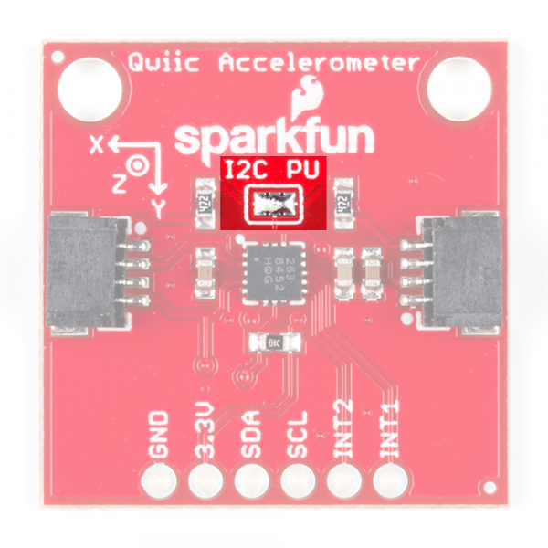
The Qwiic Accelerometer has onboard I2C pull up resistors, which can be removed by removing the solder from the jumper highlighted below. Only remove this solder if you are using your own pullups on the I2C lines.

Pull-Up Resistor Jumper

Address Select Jumper

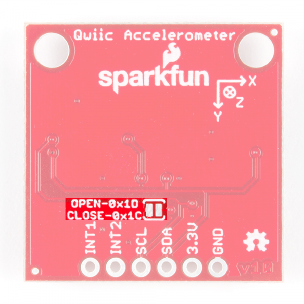
There is an additional jumper on the back of the board that allows the I2C to be changed from the default 0x1D to 0x1C if you have multiple accelerometers on the same I2C bus. However, if you have more than 2 accelerometers, you’ll need the Qwiic Mux to have them all on the same I2C bus. The jumper is highlighted below. Normally open, the jumper sets the I2C address to 0x1D. Closing the jumper with solder will give an I2C address of 0x1C.

Address select jumper

Axis Reference

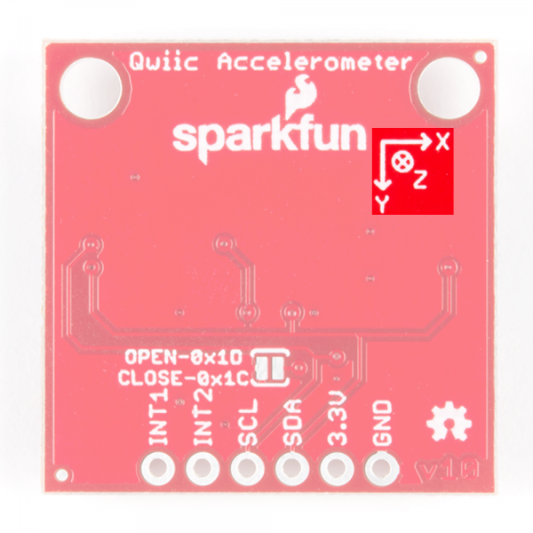
Also be sure to check out the labeling on the back of the board that indicates the orientation of the positive X, Y, and Z axes so you know what exactly your data means.

Axis Reference

Hardware Assembly

If you haven’t yet assembled your Qwiic Shield, now would be the time to head on over to that tutorial. With the shield assembled, Sparkfun’s new Qwiic environment means that connecting the sensor could not be easier. Just plug one end of the Qwiic cable into the Accelerometer breakout, the other into the Qwiic Shield of your choice and you’ll be ready to upload a sketch and figure out how far away you are from that thing over there. It seems like it’s too easy too use, but that’s why we made it that way!

Qwiic Accelerometer connected to Qwiic Arduino Shield and RedBoard

Example Code

Note: This example assumes you are using the latest version of the Arduino IDE on your desktop. If this is your first time using Arduino, please review our tutorial on installing the Arduino IDE. If you have not previously installed an Arduino library, please check out our installation guide.

We’ve written an Arduino library to make interfacing with the MMA8452Q as easy as can be. Click on the button below to download the library. Or you can grab the latest, greatest version over on the library’s GitHub repository.

Download MMA8452Q Arduino Library (ZIP)

Load Up the Example Sketch

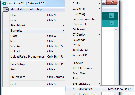
Once you’ve installed the SFE_MMA8452Q library, restart Arduino. Then go to File>Examples>SFE_MMA8452Q>MMA8452Q_Basic to open the example sketch.

Opening the example sketch

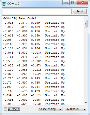
Once you’ve set your Board and Serial Port, upload the sketch to your Arduino. Then open the serial monitor. You’ll begin to see acceleration values stream by, in addition to some information about the sensor’s orientation.

Serial stream example

Try moving the sensor around to change those values. If it is motionless, flat on the desk, then an acceleration of 1g should be felt on the z-axis, while the others feel around 0. Test the other axes by rotating the board and making them feel the pull of gravity.

Using the SFE_MMA8452Q Library

Here are some tips on using the MMA8452Q Arduino library so you can embed it into an Arduino sketch of your own.

Include the Library (Global)

To begin, you need to “include” the library in your sketch:

language:c
#include <Wire.h> // Must include Wire library for I2C
#include <SFE_MMA8452Q.h> // Includes the SFE_MMA8452Q library

The library also requires that you include Wire.h in your sketch. Make sure you include that before you include the SFE_MMA8452Q.h file.

Create an MMA8452Q Object (Global)

Once the library is included, you can create an MMA8452Q object. This line of code will do it for you:

language:c
MMA8452Q accel; // Default MMA8452Q object create. (Address = 0x1D)

Optionally, you can define the 7-bit I2C address of your MMA8452Q in this parameter, using one of these lines of code:

language:c
MMA8452Q accel(0x1C); // Initialize the MMA8452Q with an I2C address of 0x1C (SA0=0)
MMA8452Q accel(0x1D); // Initialize the MMA8452Q with an I2C address of 0x1D (SA0=1)

But if you’ve left the address jumper untouched (meaning the “SA0” pin is connected to VCC), you can call the default (no parameter) constructor shown earlier.

Initialize the MMA8452Q (Setup)

Finally, in the setup() function of your sketch, you can initialize the accelerometer using the init() function. The init() function verifies communication with the accelerometer, and sets up the full-scale range and output data rate.

Again, you have a few options here. You can use a simple declaration like below. This will initialize the accelerometer with range of ±2g and an output data rate of 800 Hz (turns the accelerometer up to the max!):

language:c
accel.init(); // Default init: +/-2g and 800Hz ODR

If you want to specify the acceleration and output data rate, you can instead use an init() function like this:

language:c
accel.init([scale], [odr]); // Init and customize the FSR and ODR

Scale can be either SCALE_2G, SCALE_4G, or SCALE_8G. The “odr” variable can be either ODR_800, ODR_400, ODR_200, ODR_100, ODR_50, ODR_12, ODR_6, or ODR_1, respectively setting the data rate to 800, 400, 200, 100, 50, 12.5, 6.25, or 1.56 Hz.

Reading and Using Values

Once you’ve set the accelerometer up, you can immediately start reading the data coming out of the chip. Reading and using the values is a two-step process. First, call the read() function to pull in the values.

language:c
accel.read(); // Update acceleromter data

After you’ve called the read() function, you can use either of two sets of values to use the data. Reading from the x, y, and z class variables will return a signed 12-bit integer read straight out of the accelerometer.

language:c
xAcceleration = accel.x; // Read in raw x-axis acceleration data
Serial.print("Acceleration on the x-axis is ");
Serial.println(xAcceleration);

Or, if you want a value with physical units, you can use the cx, cy, and cz class variables. These are the calculated acceleration values read out of the accelerometer; they’ll be in units of g’s.

language:c
zAcceleration = accel.cz; // Read in calculated z-axis acceleration
Serial.print("Acceleration on the z-axis is: ");
Serial.print(zAcceleration);
Serial.println(" g's");

Remember! Those variables are only updated after the read() function is called. Make sure that happens before you start using acceleration values.

Reading Portrait/Landscape

The MMA8452Q has all sorts of nifty, extra features, one of which is orientation detection– it can estimate if it’s being held in landscape mode, portrait mode, or flat.

To read the portrait/landscape data from the accelerometer, use the readPL() function. This function returns a byte, which will either be equal to PORTRAIT_U, PORTRAIT_D, LANDSCAPE_R, LANDSCAPE_L, or LOCKOUT.

language:c
byte pl = accel.readPL();
switch (pl)
{
case PORTRAIT_U:
    Serial.print("Portrait Up");
    break;
case PORTRAIT_D:
    Serial.print("Portrait Down");
    break;
case LANDSCAPE_R:
    Serial.print("Landscape Right");
    break;
case LANDSCAPE_L:
    Serial.print("Landscape Left");
    break;
case LOCKOUT:
    Serial.print("Flat");
    break;
}

As in the example above, you can use if or switch statements to check which orientation your accelerometer is in.

Resources and Going Further

Thanks for reading! We’re excited to see what you build with the MMA8452Q. If you’re left needing more MMA8452Q-related documentation, check out some of these resources:

Need some inspiration for your next project? Check out some of these related tutorials:

Dungeons and Dragons Dice Gauntlet

A playful, geeky tutorial for a leather bracer that uses a LilyPad Arduino, LilyPad accelerometer, and seven segment display to roll virtual 4, 6, 8, 10, 12, 20, and 100 side dice for gaming.

Das Blinken Top Hat

A top hat decked out with LED strips makes for a heck of a wedding gift.

Blynk Board Washer/Dryer Alarm

How to configure the Blynk Board and app to notify you when your washer or dryer is done shaking.
New!

Raspberry Pi Zero Helmet Impact Force Monitor

How much impact can the human body handle? This tutorial will teach you how to build your very own impact force monitor using a helmet, Raspberry Pi Zero, and accelerometer!

learn.sparkfun.com | CC BY-SA 3.0 | SparkFun Electronics | Niwot, Colorado


Qwiic Distance Sensor (RFD77402) Hookup Guide

$
0
0

Qwiic Distance Sensor (RFD77402) Hookup Guide a learn.sparkfun.com tutorial

Available online at: http://sfe.io/t729

Introduction

The RFD77402 uses an infrared VCSEL (Vertical Cavity Surface Emitting Laser) TOF (Time of Flight) module capable of millimeter precision distance readings up to 2 meters. It’s also part of SparkFun’s Qwiic system, so you won’t have to do any soldering to figure out how far away things are.

SparkFun Distance Sensor Breakout - RFD77402 (Qwiic)

SEN-14539
$14.95

In this hookup guide, we’ll first get started with some basic distance readings, then we’ll add in a confidence value to ensure the sensor isn’t returning “garbage” data. Finally, we’ll increase our sample rate to obtain readings as fast as we can.

Required Materials

To get started, you’ll need a microcontroller to, well, control everything.

SparkFun RedBoard - Programmed with Arduino

DEV-13975
$19.95
25
SparkFun ESP32 Thing

DEV-13907
$19.95
52
Raspberry Pi 3

DEV-13825
$39.95
90
Particle Photon (Headers)

WRL-13774
$19.00
28

Now to get into the Qwiic ecosystem, the key will be one of the following Qwiic shields to match your preference of microcontroller:

SparkFun Qwiic Shield for Arduino

DEV-14352
$5.95
SparkFun Qwiic HAT for Raspberry Pi

DEV-14459
$4.95
1
SparkFun Qwiic Shield for Photon

DEV-14477
$4.95

You will also need a Qwiic cable to connect the shield to your distance sensor, choose a length that suits your needs.

Qwiic Cable - 500mm

PRT-14429
$1.95
Qwiic Cable - 100mm

PRT-14427
$1.50
Qwiic Cable - 200mm

PRT-14428
$1.50
Qwiic Cable - 50mm

PRT-14426
$0.95

Suggested Reading

If you aren’t familiar with our new Qwiic system, we recommend reading here for an overview. We would also recommend taking a look at the following tutorials if you aren’t familiar with them.

I2C

An introduction to I2C, one of the main embedded communications protocols in use today.

Qwiic Shield for Arduino & Photon Hookup Guide

Get started with our Qwiic ecosystem with the Qwiic shield for Arduino or Photon.

Hardware Overview

Let’s first check out some of the characteristics of the RFD77402 sensor we’re dealing with, so we know what to expect out of the board.

CharacteristicRange
Operating Voltage3.3V
Current7 mA average at 10Hz
Measurement Range~50mm to 2,000mm
Precision+/-10%
Light Source850nm VCSEL
I2C Address0x4C
Field of View55&deg
Field of Illumination23&deg
Max Read Rate10Hz (We've seen up to 20Hz in practice)

Pins

The following table lists all of the RFD77402’s pins and their functionality.

PinDescriptionDirection
GNDGroundIn
3.3VPowerIn
SDADataIn
SCLClockIn
INTInterrupt, goes low when data is ready.Out

Optional Features

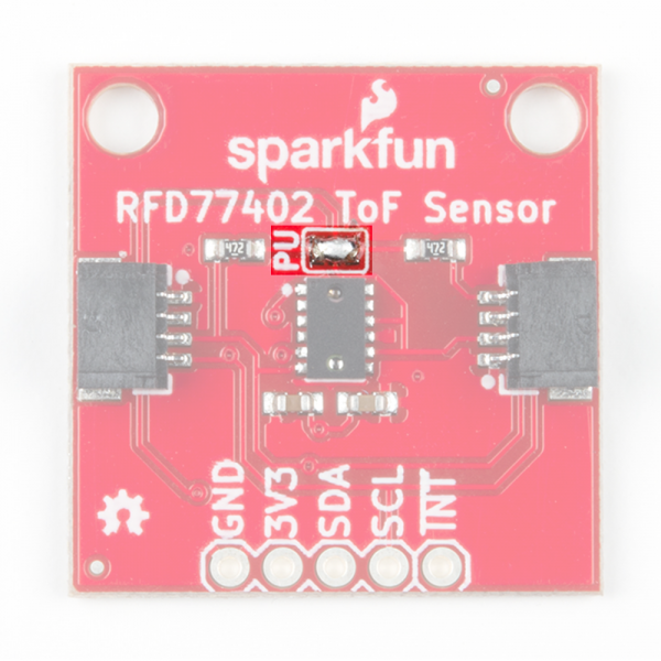
The RFD77402 breakout has onboard I2C pull up resistors, which can be removed by removing the solder from the jumper highlighted below.

Pull Up Resistors Jumper

Hardware Assembly

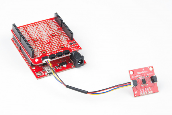
If you haven’t yet assembled your Qwiic Shield, now would be the time to head on over to that tutorial. With the shield assembled, Sparkfun’s new Qwiic environment means that connecting the sensor could not be easier. Just plug one end of the Qwiic cable into the RFD77402 breakout, the other into the Qwiic Shield and you’ll be ready to upload a sketch and figure out how far away you are from that thing over there. It seems like it’s too easy too use, but that’s why we made it that way!

Qwiic Distance Sensor Connected to Qwiic Shield Stacked on RedBoard

Library Overview

Note: This example assumes you are using the latest version of the Arduino IDE on your desktop. If this is your first time using Arduino, please review our tutorial on installing the Arduino IDE. If you have not previously installed an Arduino library, please check out our installation guide.

First, you’ll need to download SparkFun’s RFD77402 Library. This can be done by using the below button or by utilizing the Arduino library manager. You can also grab the latest, greatest version over on the library’s GitHub repository.

Download SparkFun RFD77402 Library (ZIP)

Before getting started, let’s check out the publicly available functions of our library.

  • boolean begin(TwoWire &wirePort = Wire, uint32_t i2cSpeed = I2C_SPEED_STANDARD);— Initializes the RFD77402 sensor on a given I2C bus, with a given I2C speed. This function will default to the primary I2C bus and standard I2C speed if called without any arguments.
  • uint8_t takeMeasurement();— Takes a single measurement and sets the global variables with new data.
  • uint16_t getDistance();— Returns the local variable distance to the caller.
  • uint8_t getValidPixels();— Returns the number of valid pixels found when taking measurement.
  • uint16_t getConfidenceValue();— Returns the qualitative value representing how confident the sensor is about its reported distance.
  • uint8_t getMode();— Read the command opcode and convert to the corresponding mode.
  • boolean goToStandbyMode();— Tell MCPU to go to standby mode. Return true if successful.
  • boolean goToOffMode();— Tell MCPU to go to off state. Return true if successful.
  • boolean goToOnMode();— Tell MCPU to go to on state. Return true if successful.
  • boolean goToMeasurementMode();— Tell MCPU to go to measurement mode. Takes a measurement. If measurement data is ready, return true.
  • uint8_t getPeak();— Returns the VCSEL peak 4-bit value.
  • void setPeak(uint8_t peakValue);— Sets the VCSEL peak 4-bit value.
  • uint8_t getThreshold();— Returns the VCSEL Threshold 4-bit value.
  • void setThreshold(uint8_t threshold);— Sets the VCSEL Threshold 4-bit value.
  • uint8_t getFrequency();— Returns the VCSEL Frequency 4-bit value.
  • void setFrequency(uint8_t threshold);— Sets the VCSEL Frequency 4-bit value.
  • uint16_t getMailbox();— Gets whatever is in the ‘MCPU to Host’ mailbox. Check Interrupt Control Status Register bit 5 before reading.
  • void reset();— Software reset the device
  • uint16_t getChipID();— Returns the chip ID. Should be 0xAD01 or higher.
  • boolean getCalibrationData();— Retrieves 2 sets of 27 bytes from MCPU for computation of calibration parameters. 54 bytes are read into the calibration array, true is returned if new calibration data is loaded successfully.
  • uint16_t readRegister16(uint8_t addr);— Reads two bytes from a given location from the RFD77402.
  • uint8_t readRegister(uint8_t addr);— Reads from a given location from the RFD77402.
  • void writeRegister16(uint8_t addr, uint16_t val);— Write a 16 bit value to a spot in the RFD77402.
  • void writeRegister(uint8_t addr, uint8_t val);— Write a value to a spot in the RFD77402.

Example Code

You should have downloaded the SparkFun RFD77402 Library in the previous step, if not, go back to the previous step and go ahead and download it as you’ll be needing it shortly. This hookup guide goes over the 3 examples contained within the library.

Example 1 - Basic Readings

Example 1 gets us started taking some basic distance readings from the sensor. Simply upload the example code below, open your serial monitor with a baud rate of 9600 and start getting readings!

language:c
#include <SparkFun_RFD77402_Arduino_Library.h> //Use Library Manager or download here: https://github.com/sparkfun/SparkFun_RFD77402_Arduino_Library
RFD77402 myDistance; //Hook object to the library

void setup()
{
  Serial.begin(9600); //Begins Serial communication
  while (!Serial);
  Serial.println("RFD77402 Read Example");

  if (myDistance.begin() == false) //Initializes the sensor. Tells the user if initialization has failed.
  {
    Serial.println("Sensor failed to initialize. Check wiring.");
    while (1); //Freeze!
  }
  Serial.println("Sensor online!");
}

void loop()
{
  myDistance.takeMeasurement(); //Tell sensor to take measurement and populate distance variable with measurement value

  unsigned int distance = myDistance.getDistance(); //Retrieve the distance value

  Serial.print("distance: "); //Print the distance
  Serial.print(distance);
  Serial.print("mm");
  Serial.println();
}

The first example simply outputs distances one after another, the output should look something like the image below.

Qwiic Distance Sensor Example 1 Output

Example 2 - Confidence Values

The second example gets us going on rejecting or accepting our data as a successful reading (i.e. the sensor is not maxed out). This is done simply by using the getConfidenceValue() function, which returns a value anywhere between 0 and 2047, with 2047 being the “most confident”. In other words, a confidence value of 2047 means that the sensor is getting a very strong, clean, TOF flight reading. This is a great way to ignore any data that is out of the sensors range. The below example code will get you started taking these confidence readings. This sketch will also check the distance value against error codes to see if the sensor is giving us an error, and if so, which one.

language:c
#include <SparkFun_RFD77402_Arduino_Library.h> //Use Library Manager or download here: https://github.com/sparkfun/SparkFun_RFD77402_Arduino_Library
RFD77402 myDistance; //Hook object to the library

void setup()
{
  Serial.begin(9600);
  while (!Serial);
  Serial.println("RFD77402 Read Example");

  if (myDistance.begin() == false)
  {
    Serial.println("Sensor failed to initialize. Check wiring.");
    while (1); //Freeze!
  }
  Serial.println("Sensor online!");
}

void loop()
{

  byte errorCode = myDistance.takeMeasurement();
  if (errorCode == CODE_VALID_DATA) //Checks to see that data is not any of the error codes
  {
    unsigned int distance = myDistance.getDistance();
    byte pixels = myDistance.getValidPixels();
    unsigned int confidence = myDistance.getConfidenceValue(); //Pulls the confidence value from the sensor

    Serial.print("distance: ");
    Serial.print(distance);
    Serial.print("mm pixels: ");
    Serial.print(pixels);
    Serial.print(" confidence: ");
    Serial.print(confidence);

//Error Codes are outlined below

    if(distance > 2000) Serial.print(" Nothing sensed");
  }
  else if (errorCode == CODE_FAILED_PIXELS)
  {
    Serial.print("Not enough pixels valid");
  }
  else if (errorCode == CODE_FAILED_SIGNAL)
  {
    Serial.print("Not enough signal");
  }
  else if (errorCode == CODE_FAILED_SATURATED)
  {
    Serial.print("Sensor pixels saturated");
  }
  else if (errorCode == CODE_FAILED_NOT_NEW)
  {
    Serial.print("New measurement failed");
  }
  else if (errorCode == CODE_FAILED_TIMEOUT)
  {
    Serial.print("Sensors timed out");
  }

  Serial.println();
}

Opening the serial monitor to 9600 baud should yield an output similar to the one shown earlier.

Qwiic Distance Sensor Example 2 Output

Example 3 - Fast Readings

The following example allows you to use your distance sensor not only to measure distance but time in between samples as well. Enabling a faster I2C speed cuts down on the time where we are talking to the sensor, so we are able to accurately guage time in between readings. This allows the user to compute velocity and even acceleration if they’d like. Check out the Equations of Motion for a little bit better explanation if you’re new to physics.

In the below example, make note of two things, the first is in the setup() function. Notice how we call a non-default begin() function that initializes the sensor with I2C_SPEED_FAST, which increases the clock speed on the I2C bus. The second thing to make note of are the three lines at the beginning of our void loop(), which starts the timer function and allows us to know the time in between readings.

language:c
#include <SparkFun_RFD77402_Arduino_Library.h> //Use Library Manager or download here: https://github.com/sparkfun/SparkFun_RFD77402_Arduino_Library
RFD77402 myDistance; //Hook object to the library

void setup()
{
  Serial.begin(115200);
  while (!Serial);
  Serial.println("RFD77402 Read Example");

  //Initialize sensor. Tell it use the Wire port (Wire1, Wire2, softWire, etc) and at 400kHz (I2C_SPEED_FAST or _NORMAL)
  if (myDistance.begin(Wire, I2C_SPEED_FAST) == false)
  {
    Serial.println("Sensor failed to initialize. Check wiring.");
    while (1); //Freeze!
  }
  Serial.println("Sensor online!");
}

void loop()
{
  long startTimer = millis();
  byte errorCode = myDistance.takeMeasurement();
  long timeDelta = millis() - startTimer;

  if (errorCode == CODE_VALID_DATA)
  {
    unsigned int distance = myDistance.getDistance();
    byte pixels = myDistance.getValidPixels();
    unsigned int confidence = myDistance.getConfidenceValue();

    Serial.print("distance: ");
    Serial.print(distance);
    Serial.print("mm timeDelta: ");
    Serial.print(timeDelta);

    if(distance > 2000) Serial.print(" Nothing sensed");
  }
  else if (errorCode == CODE_FAILED_PIXELS)
  {
    Serial.print("Not enough pixels valid");
  }
  else if (errorCode == CODE_FAILED_SIGNAL)
  {
    Serial.print("Not enough signal");
  }
  else if (errorCode == CODE_FAILED_SATURATED)
  {
    Serial.print("Sensor pixels saturated");
  }
  else if (errorCode == CODE_FAILED_NOT_NEW)
  {
    Serial.print("New measurement failed");
  }
  else if (errorCode == CODE_FAILED_TIMEOUT)
  {
    Serial.print("Sensors timed out");
  }

  Serial.println();
}

Opening the serial monitor to 115200 baud should yield something like the below image.

Qwiic Distance Sensor Example 3 Output

Resources and Going Further

Now that you know exactly how far away that thing is, it’s time to incorporate it into your own project! For more on the Qwiic Distance Sensor (RFD77402), check out the links below:

Need some inspiration for your next project? Check out some of these related tutorials:

VL6180 Hookup Guide

Get started with your VL6180 based sensor or the VL6180 breakout board.

Building an Autonomous Vehicle: The Batmobile

Documenting a six-month project to race autonomous Power Wheels at the SparkFun Autonomous Vehicle Competition (AVC) in 2016.

LIDAR-Lite v3 Hookup Guide

A tutorial for connecting the Garmin LIDAR-Lite v3 to an Arduino to measure distance.

learn.sparkfun.com | CC BY-SA 3.0 | SparkFun Electronics | Niwot, Colorado

How to Use a Hot Air Rework Station

$
0
0

How to Use a Hot Air Rework Station a learn.sparkfun.com tutorial

Available online at: http://sfe.io/t592

Introduction

Hot-air stations or heat guns are very useful tools and are essential for any electronics workbench. When working with or building printed circuit boards, there is a lot of room for errors to be made. Whether you’re relying on machines to do the building for you or building by hand, solder can often have a mind of its own. Sometimes the person doing the building (or the person programming the machine that does the building) can make a mistake. Other times, the solder or components on the PCB can react in ways that are not desirable during reflow. Have no fear though, there are ways to remedy this! The SparkFun hot-air rework station - 303D is one such solution.

Hot-Air Rework Station - 303D

TOL-14557
$114.95
1

Tools

Besides a hot-air rework station, you’ll need a few tools to rework a surface mount components on a board. The tweezer type will depend on the job and personal preference. Flux can also help reflow solder joints.

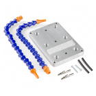
SparkFun Third Hand Kit

TOL-11784
$29.95
51
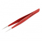
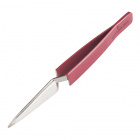
Tweezers - Straight (ESD Safe)

TOL-10603
$3.95
2
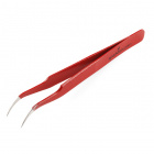
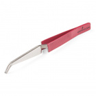
Tweezers - Curved (ESD Safe)

TOL-10602
$3.95
4
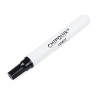
Chip Quik No-Clean Flux Pen  - 10mL

TOL-14579
$7.95
1
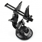
Panavise Jr. - Vacuum Base

TOL-10410
$32.95
Tweezers - Curved (cross-lock, ESD Safe)

TOL-12572
$3.95
1
Tweezers - Straight (cross-lock, ESD Safe)

TOL-12573
$3.95

Additional Tools

To protect your table’s finish, we recommend using a heat resistant material.

  • Heat Resistant Material
    • Piece of Medium Density Fiberboard (MDF)
    • Silicone Mat

If this is the first time that you have reworked a board, try reworking a scrap board from our ding and dent before reworking an expensive PCB!

Scrap Boards

DD-08477
4
Pick and Place Spare Parts Grab Bag

DD-10351

Hardware Overview

Let’s take a look at the features starting on the upper right side of the 303D hot air rework station.

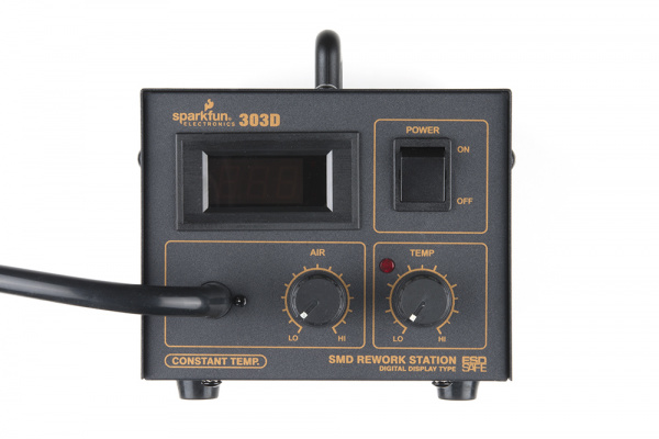
Hot Air Rework Station Face

Power Switch– The 303D uses a standard North American plug/outlet (~110VAC). Hopefully the power on/off switch is self-explanatory. Move the switch to “ON” to turn the hot-air rework station on, move the switch to “OFF” to turn the hot-air rework station off. Easy peasy.

LED Digital Output– The LED digital output lists both your temperature range as well as your air flow. The display will change as you turn either the air or temperature knobs.

Air Flow Grade– Air flow grades range from A25 ~ A99. You can adjust the air flow by turning the air setting knob. The LED output will display the setting air flow grade for 2 seconds and then return to the current air temperature of the nozzle.

Temperature Range– Output temperatures range from 100° ~ 480° Celsius. You can adjust the working temperature by turning the temperature setting knob. The LED output will display the setting temperature for 3 seconds and then return to the actual air temperature of the nozzle. The indicator in the temperature box will twinkle when the desired temperature is reached.

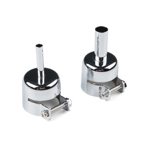
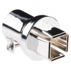
Nozzles– The 303D comes with 2x changeable hot-air nozzles. The smaller nozzle is good for focusing the hot air on smaller components. The bigger nozzle is great if you are trying to focus hot air around a big area on the board.

Interchangeable hot air nozzles

Wand Holder– The unit comes with a wand holder for the hot air gun. It can be attached on either side of the hot air rework station.

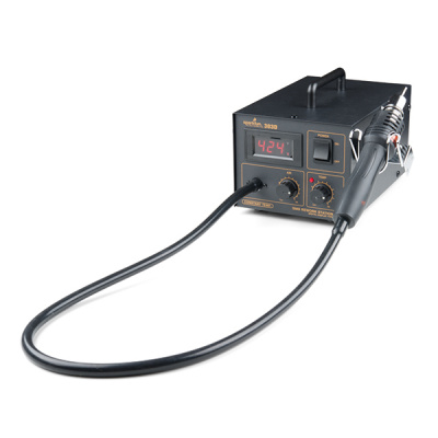
Hot Air Rework Station

Wand Holder Attached to the Right Side While Powered

What's It Good For?

Hot-air rework stations can be very handy. As mentioned above, they are a crucial tool when it comes to reworking a board. The term rework just means you are refinishing or repairing an already reflowed board, and it is a term commonly used in the electronics world. Just think of it as doing any work to the board that wasn’t involved in the actual production process. Here are some common rework scenarios:

  • Polarized Components - Parts that have been placed incorrectly (backwards, shifted x degrees off). These include ICs, diodes, some capacitors, connectors, etc.

  • Tombstone Parts - This is when a part (usually a resistor or capacitor) reflows only on one side. The part usually sticks strait up resembling a tombstone.

  • Cold Joints - This is similar to a tombstone except the parts might not be sticking strait up, making it harder to see the connection that is not being made.

  • Removing Defective Parts - Sometimes, during the IC manufacturing process, errors can arise and go unnoticed. These ICs are then placed on perfectly good PCBs. Hot-air is great for replacing these bad parts.

  • Missing Components - The smaller the component, the easier it is for it to disappear. This can happen before or during reflow, resulting in a spot where something should be, but isn’t. Hot-airing a new part in its place is a snap with this rework station.

  • Unintentional Solder Jumpers - If too much solder or solder paste is used, the result can be jumpers on one or more of your surface mount IC’s legs. Hot-air can sometimes be used in conjunction with a flux pen to remove these pesky buggers.

Other Uses

Rework isn’t the only thing a hot-air rework station is good for. Other uses include:

  • Salvaging electronic components from old PCBs.
  • Reflowing solder paste applied with a stencil between SMD components and a PCB.
  • Shrinking heat-shrink to secure wire connections.
  • Heating up and bending certain plastics (with the correct settings).
  • Heating up hot glue to remove or reposition items that were glued incorrectly.

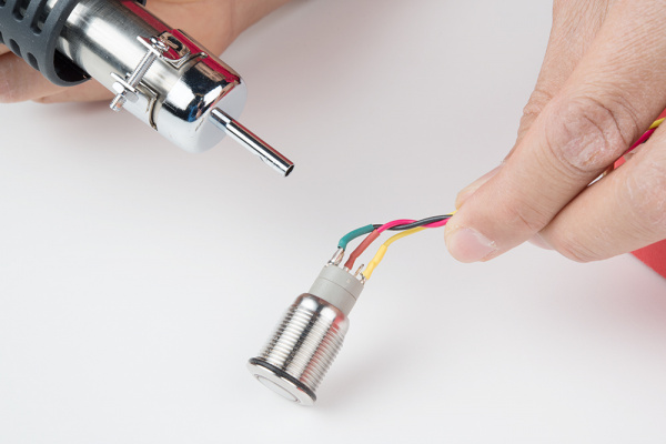
Heat Shrink for a More Secure Connection

How to Use a Hot Air Rework Station

Choose Your Nozzle

Choose the appropriate tip for the job. Attach the nozzles to the wand and tighten the screw using a screw driver to hold it in place.

Plug the 303D’s North American standard plug into your very favorite US outlet (~110VAC). The heating element and blower will remain off until you flip the power switch to ON.

Power On

Flip said power switch to ON. The heating element will fire up and the air will get very hot, very quickly so aim the nozzle accordingly. The red LED next to the “SET TEMP” will pulse, indicating that “Hey, I’m ready to melt some stuff.” Wait for the hot-air station to warm up before using it.

Adjust Air and Temperature

There are two control knobs – one for airflow and one for temperature. Adjust them to suit your needs.

Rework

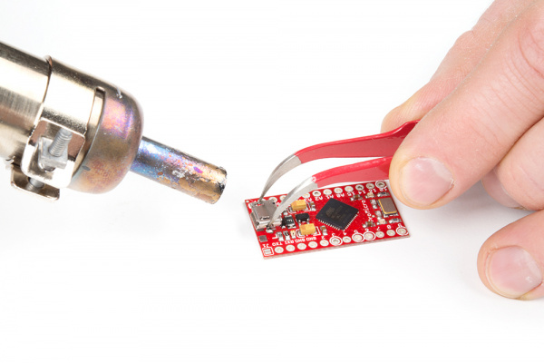
When you’ve got your settings honed in, carefully aim the nozzle at the area you are working on. Saying the magic spell (meltum, meltum, meltum), move the nozzle back and forth until the solder begins to flow (the solder should appear shiney and molten). Then carefully remove/reposition the part you want to rework using tweezers by nudging or grabbing the part. Keep in mind that hot-air is, well, hot.

micro-B Connector Removed

A micro-B Connector Being Removed from a Pro Micro for a Tech Prank. Be sure to rework the board on a heat resistant material!

Cool Down

When you are done, flip the power switch to OFF to allow the station to cool down when finished. The self-cooling will kick on and last for a few minutes.

Clean

Wash your board when you’re finished to remove any water soluble flux left on the board, which can cause corrosion over time.

Demo Video

Below is a demo video from our pal Dave Stillman showing us how to use our SparkFun Hot-air Rework Station properly!

Replacement Parts

Nozzles

Hot-air Rework Nozzles - Y1126

TOL-07925
$14.95

Heating Elements

Hot-air Rework Replacement Element - Temp Controlled

TOL-11130
$19.95

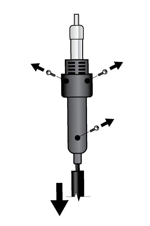
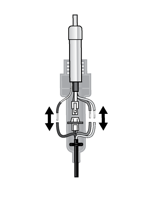
Replacing the Heating Element:

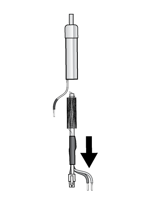
Remove ScrewsUnplugRemove Heating Element

Troubleshooting

Low Airflow when “Air” Dial is Turned Up

If you are getting low airflow when the “Air” Dial is turned up, make sure that you have the nozzle securely attached. With the nozzle, you will get more air flowing through the hot-air rework station’s handle.

S-E Error

“S-E” usually means Sensor Error. It’s a common error. Sometimes it goes away after messing with the dial and the temperature will display properly again. Other times it indicates that the heat sensor is failing. The rework station might be able to be revived by removing and re-attaching the heater. Another tech support rep thinks it’s oxide building up on the connections. This results in fooling the controller into thinking the heater has failed.

H-E Error

Units displaying the “H-E” usually means there is a heating error. It might be that there is something with the heating element failing or not connected properly. Try checking the connections to see if the heating element needs to be re-seated. Last resort is getting a replacement heating element. A last resort is getting a replacement heating element.

Air Turned Too High

If your air flow is turned up too high, it is quite possible that you will start seeing small projectiles shooting away from your board. Those are your parts. We recommend starting at a lower air flow and moving up as your needs require.

Destroying a PCB

If you sit too long on a given spot on a PCB while working with hot-air, the glue that holds the copper layer to the FR4 laminate underneath lets go and comes out as black goo. The green soldermask on the top side also begins to come off. Because we don’t have Smell-a-vision yet, we can try to describe the smell - it’s horrendous. It smells like burning electronics (surprise) but the smell seems to cling to your skin and clothes. Not cool. So practice and don’t be surprised if you smell bad things with your first couple re-work attempts.

Pulled Pads

When checking to see if a part is ready to move, we recommend nudging the part gently. If you push too hard, you can pull the pad.

Resources and Going Further

If you have any questions or comments, please feel free to drop them in the comments box below. Happy reworking!

For more information about the hot-air rework station, check out the resources below:

Check out these other great tutorials from Sparkfun to level up your skills!

Designing PCBs: Advanced SMD

Advanced Eagle layout for PCBs with SMD devices.

How to Solder - Castellated Mounting Holes

Tutorial showing how to solder castellated holes (or castellations). This might come in handy if you need to solder a module or PCB to another PCB. These castellations are becoming popular with integrated WiFi and Bluetooth modules.

Planning a Wearable Electronics Project

Tips and tricks for brainstorming and creating a wearables project.

Reducing Arduino Power Consumption

A tutorial about different ways to reduce the current draw for your next Arduino project the easy way.

learn.sparkfun.com | CC BY-SA 3.0 | SparkFun Electronics | Niwot, Colorado

TFMini - Micro LiDAR Module Hookup Guide

$
0
0

TFMini - Micro LiDAR Module Hookup Guide a learn.sparkfun.com tutorial

Available online at: http://sfe.io/t742

Introduction

The TFMini is a ToF (Time of Flight) LiDAR sensor capable of measuring the distance to an object as close as 30 cm and as far as 12 meters! The TFMini allows you to integrate LiDAR into applications traditionally reserved for smaller sensors such as the SHARP GP-series infrared rangefinders. In this tutorial, you will learn how to connect to the TFMini using an Arduino microcontroller.

TFMini - Micro LiDAR Module

SPX-14588
$39.95

Required Materials

To follow along with this tutorial, you will need the following materials. You may not need everything though depending on what you have. Add it to your cart, read through the guide, and adjust the cart as necessary.

SparkFun RedBoard - Programmed with Arduino

DEV-13975
$19.95
25
SparkFun Logic Level Converter - Bi-Directional

BOB-12009
$2.95
84
Breadboard - Self-Adhesive (White)

PRT-12002
$4.95
35
Break Away Headers - Straight

PRT-00116
$1.50
20
SparkFun USB Mini-B Cable - 6 Foot

CAB-11301
$3.95
2
Jumper Wires Standard 7" M/M - 30 AWG (30 Pack)

PRT-11026
$1.95
20

Tools

You will need a soldering iron, solder, and general soldering accessories.

Solder Lead Free - 100-gram Spool

TOL-09325
$7.95
7
Weller WLC100 Soldering Station

TOL-14228
$44.95

Suggested Reading

If you aren’t familiar with the following concepts, we recommend checking out these tutorials before continuing.

Serial Communication

Asynchronous serial communication concepts: packets, signal levels, baud rates, UARTs and more!

Installing an Arduino Library

How do I install a custom Arduino library? It's easy!

Logic Levels

Learn the difference between 3.3V and 5V devices and logic levels.

Hardware Overview

The sensor works by sending a modulated near-infrared light out. The light that is reflected from the object returns to the sensor’s receiver. The distance between the two can be converted using the sensor by calculating the time and phase difference. The distance measured may vary depending on the environment and the reflectivity of object.

Input Power and Logic Levels

According to the datasheet (pg 4) the input voltage is between 4.5V-6V. In this tutorial, we will be applying 5V to the sensor.

Logic Levels

While the sensor can be powered at 5V, the serial UART pins are only 3.3V logic. Make sure to use a logic level converter when reading the sensor with a 5V microcontroller.

Pinout

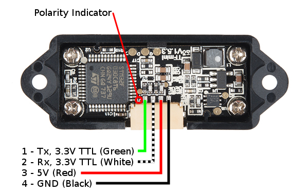
There is a marking next to the polarized connector to indicate the polarity as “J1” as indicated in the image below. This is useful when referencing sensor’s pinout.

TFMini  Pinout

Pin NumberTFMini PinoutWire Color
1UART_TX (3.3V TTL)Green
2UART_RX (3.3V TTL)White
35VRed
4GNDBlack

Hardware Hookup

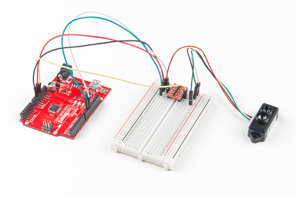
For the purpose of this tutorial, we will be using a 5V Arduino. A microcontroller and logic level converter is required in order to read the sensor values through the serial UART pins. Make sure to solder the male header pins to the converter before making the connections on a breadboard. Begin by making a connection from an Arduino’s high side and following the connection to the TFMini. Then continue to make the rest of the connections by following the hookup table listed below.

5V Arduino w/ Atmega328PLogic Level Converter (High Side)Logic Level Converter (Low Side)TFMini
Software Serial RX
(Pin 10)
HV1LV1UART_TX (3.3V TTL)
(Pin 1)
Software Serial TX
(Pin 11)
HV4LV4UART_RX (3.3V TTL)
(Pin 2)
3.3VLV
5VHVVin (4.5V-6V)
(Pin 3)
GNDGNDGNDGND
(Pin 4)

Once we are finished, it should look like the image below.

Connecting the TFMini with Arduino

Example Code

Note: This example assumes you are using the latest version of the Arduino IDE on your desktop. If this is your first time using Arduino, please review our tutorial on installing the Arduino IDE. If you have not previously installed an Arduino library, please check out our installation guide.

Download and install the Arduino library from the GitHub Repository. You can also download the library from the button below.

Download TFMini Arduino Library (ZIP)

Grab a mini-USB cable and connect the Arduino to your computer. Upload the BasicReading.ino that was included in the library’s examples to your Arduino. Make sure to use the correct COM port and board selection.

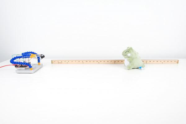
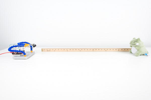
Once uploaded, try moving an object in front of the sensor to test. In the example below, a third hand was used to hold the TFMini when detecting an object at a certain distance away from the sensor. Since the sensor is not able to detect an object when less than 11.8 inches (or 30cm = 0.3m) away, the object under test was placed at 20 inches and 30 inches.

TFMini Reading an Object at 20 InchesTFMini Reading an Object at 30 Inches

Opening the serial monitor at 115200, you may see an output similar to the values printed below. Using a yard stick, the values responded as expected when moving an object between 20 inches and 30 inches.

Initializing...
54 cm      sigstr: 457
54 cm      sigstr: 456
55 cm      sigstr: 456
54 cm      sigstr: 456
54 cm      sigstr: 457
67 cm      sigstr: 340
70 cm      sigstr: 315
71 cm      sigstr: 315
77 cm      sigstr: 283
77 cm      sigstr: 284
78 cm      sigstr: 281
78 cm      sigstr: 282
78 cm      sigstr: 283

Resources and Going Further

Now that you’ve successfully got your TFMini up and running, it’s time to incorporate it into your own project! For more on the TFMini, check out the links below:

Need some inspiration for your next project? Check out some of these related tutorials:

VL6180 Hookup Guide

Get started with your VL6180 based sensor or the VL6180 breakout board.

Building an Autonomous Vehicle: The Batmobile

Documenting a six-month project to race autonomous Power Wheels at the SparkFun Autonomous Vehicle Competition (AVC) in 2016.

LIDAR-Lite v3 Hookup Guide

A tutorial for connecting the Garmin LIDAR-Lite v3 to an Arduino to measure distance.
New!

Qwiic Distance Sensor (RFD77402) Hookup Guide

The RFD77402 uses an infrared VCSEL (Vertical Cavity Surface Emitting Laser) TOF (Time of Flight) module capable of millimeter precision distance readings up to 2 meters. It’s also part of SparkFun’s Qwiic system, so you won’t have to do any soldering to figure out how far away things are.

learn.sparkfun.com | CC BY-SA 3.0 | SparkFun Electronics | Niwot, Colorado

Interactive 3D Printed Lit Diamond Prop

$
0
0

Interactive 3D Printed Lit Diamond Prop a learn.sparkfun.com tutorial

Available online at: http://sfe.io/t762

Introduction

My students had a dance performance with the theme “Night at the Movies.” I decided to choose a story based on “The Diamond” episode from the old Mission: Impossible television show. To make it fun for the kids and convey the story better to the audience, I decided to build an interactive 3D printed diamond. In this tutorial, you will learn how to 3D print a model and embed electronics in a theatrical prop.

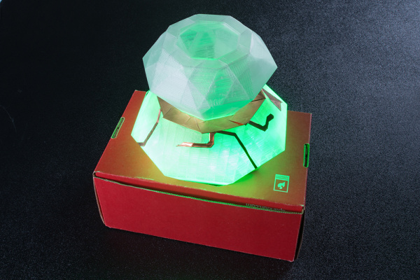
Capacitive Touch 3D Printed Lit LED Diamond Prop

Required Materials

To follow along with this project tutorial, you will need the following materials. You may not need everything though depending on what you have. Add it to your cart, read through the guide, and adjust the cart as necessary.

Tools

You will need a soldering tools, a 3D printer, and a hobby knife.

TAZ 6 3D Printer

TOL-13880
$2,499.95
2
Solder Lead Free - 100-gram Spool

TOL-09325
$7.95
7
Weller WLC100 Soldering Station

TOL-14228
$44.95
Hobby Knife

TOL-09200
$2.95
2

You will also need:

Suggested Reading

If you aren’t familiar with the following concepts, we recommend checking out these tutorials before continuing.

How to Power a Project

A tutorial to help figure out the power requirements of your project.

Installing Arduino IDE

A step-by-step guide to installing and testing the Arduino software on Windows, Mac, and Linux.

Resistors

A tutorial on all things resistors. What is a resistor, how do they behave in parallel/series, decoding the resistor color codes, and resistor applications.

Transistors

A crash course in bi-polar junction transistors. Learn how transistors work and in which circuits we use them.

AT42QT101X Capacitive Touch Breakout Hookup Guide

Learn how to use the simple SparkFun AT42QT1010 and AT42QT1011 capacitive touch breakout boards.

3D Print It

I do not have much experience with 3D printing and modeling complex shapes. Luckily, there were a few models of diamonds listed online that I found to save on time. After browsing Thingiverse, the model that I found appealing was “Oopee’s” diamond lampshade. Head over to the thing and download to print the model of your size.

Thingiverse: Diamond Lampshade

Printing a medium size diamond was sufficient and easy to see on stage as a prop. Caution is advised for printing large scale models due to time and material used.

A Small World, After All?

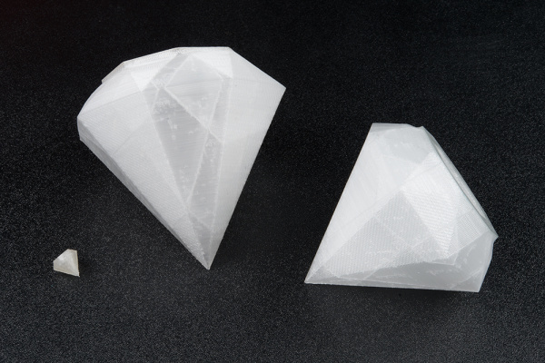
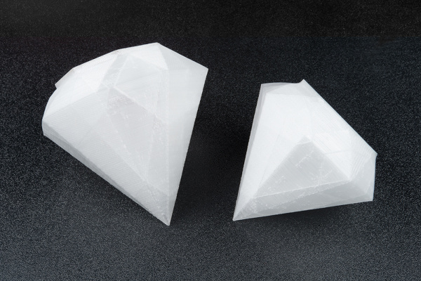
To start, I printed a small scale version of the diamond lampshade in Cura to see how it would look. The diamond on the bottom left shows the first print of the diamond against the larger prints. Satisfied with the small print. I decided to go bigger!

Test print of small model relative to larger models

Big Trouble in Little… Nozzle

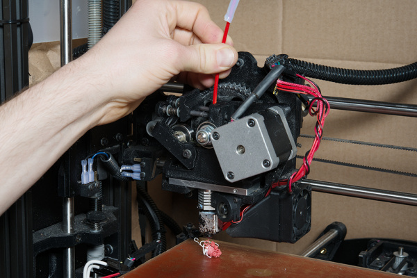
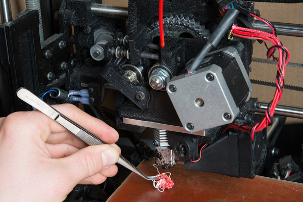
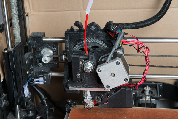
I decided to go big and start printing the diamond. Unfortunately, I ran into an issue once the print started. The 3D printer's extruder kept getting clogged causing the print to fail. I tried using a needle to clean the nozzle and manually feeding more material in the extruder. This fixed the problem temporarily but the issue kept coming up.

3D Print Fails

Doing a search online and inspecting the setup, there were a few possible reasons why this might have been happening:

  • incorrect idler tension
  • speed of the print
  • poor quality filament
  • filament tangled in spool
  • clogged extruder

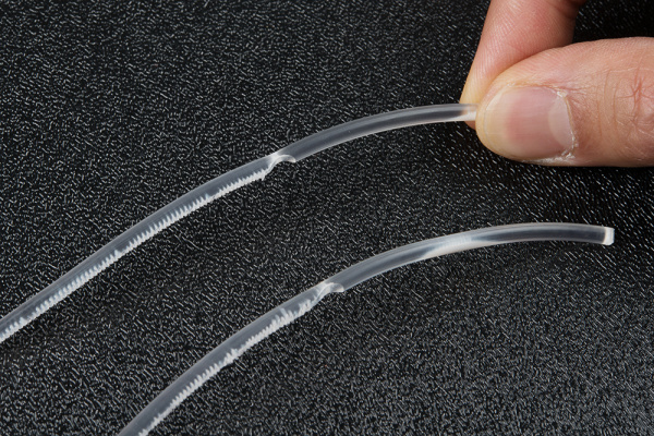
A clogged extruder seemed to be a plausible explanation of what was going on. Checking in with someone more knowledgeable about 3D printing at SparkFun, I headed over to a mechanical engineer for advice and showed him a few of the stripped filaments as shown below.

stripped filaments

He was able to confirm my assumption. With the technical support's 3D printer being used communally, he explained that the clogged extruder was probably due to either:

  • impurities from poor quality filament (as stated above)
  • changing filament material (PLA to ABS)

Acetone Bath

So how would you fix the clogged extruder? An acetone bath! This was a last resort considering my previous efforts had failed. After removing the tool head from the Lulzbot 3D printer, we carefully removed the hot end's nozzle using some pliers. And by careful, we had to avoid breaking the thermistor attached to the hot end. Once removed, a glass jar was filled just enough to submerge the nozzle tip in acetone and cleaned with a Q-tip over the course of 2 days.

Insufficient Filament and Recycling a Failed Print

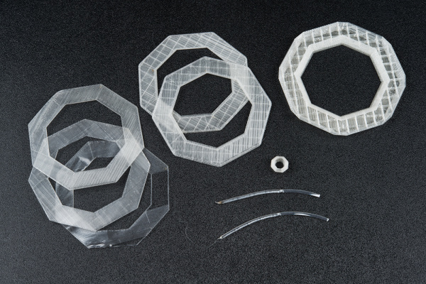
While the nozzle was being cleaned, our mechanical engineer was kind enough to allow me to use the mechanical engineering's 3D printer. Off I went to print the big diamond. However, I ran into yet another problem. I did not have enough material! I was too ambitious and did not keep track of the amount of material I had available. 30 hours into the print, I ran out of material as you can see from the image below. While the print failed, I decided to recycle the failed print by making it into a diamond holder.

Filed Print Again

A Happy Medium

Success! On my 10th attempt with a replenished supply of clear filament, I was able to successfully print a diamond. I found a happy medium of printing a diamond. After learning some lessons from the failed prints, I reduced the amount of material used between the walls and reduced the size of the model to a smaller size. Confident in the print, I printed another diamond slightly larger.

Medium

Understanding Your Circuit

Circuit Diagram

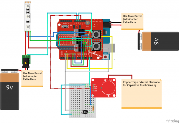
Check out the circuit diagram below to see how everything is connected.

Interactive 3D Printed Lit Diamond Prop with Capacitive Touch Sensing Fritzing Circuit

Having trouble seeing the circuit? Click the image for a closer look.

Remote Power

During rehearsals, the prop was initially powered by a 12V wall adapter. It was bulky and not ideal for quick set changes between pieces. Therefore, I decided make it portable using a 9V battery to power the LED strip and controller.

After testing, I noticed that the 9V battery connected to the Arduino's microcontroller not sufficient enough for the LED strip. The LED strip was not bright enough or would display the wrong color.To remedy this, a second 9V battery was attached to the LED strip. Ground was connected to both batteries for reference.

Controlling the LEDs

Since the non-addressable RGB LED strip operate at a higher voltage, a transistor was needed to prevent damage to the microcontroller. A pull-down resistor was also needed so that the Arduino would not have a floating pin. Each color required one n-channel mosfet and one 10kΩ resistor.

Momentary Button to Capacitive Touch Sensing

Initial testing included momentary push buttons with code utilizing the pull-up resistors on the digital pins. One button (connected to pin 2 with a white wire) was used to adjust the color while the other (connected to pin 3 with a yellow wire) was used to change the pattern. The buttons were left on the board to troubleshoot connections.

Eventually, the button to trigger the color was replaced with a capacitive touch sensor and external electrodes. The Arduino had issues reading the capacitive touch sensor’s “OUT” pin by itself so a small npn transistor was added to trigger the button press. A resistor was used as current limiting resistor to the BJT’s base pin.

Hardware Hookup

Non-Addressable RGB LED Strip

With some non-addressable RGB LED strips left over from a previous project, I decided to cut down the remaining strip and solder male jumper wire with male pins. To make it easier, you could use a 4-pin polarized connector and a 1M sealed strip. For the scope of this tutorial, we will be modifying the LED strip and using male jumper wires.

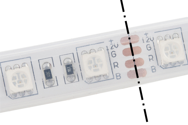
Cut the LED strip at the center of the exposed pads using a diagonal cutter. The dot and dashed line in the image below is where you will need to perform the cut. Make sure to remove part of the silicone tube in order to be able to access the LED strip’s pads.

Cut between the LED Strip's Pads

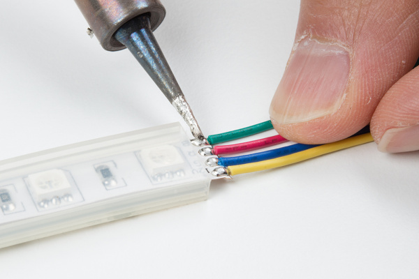
Cut half of the 12" premium jumper wires and strip the insulation. Then solder the wires to each of the LED strip’s pads.

Solder Wires to LED Strip

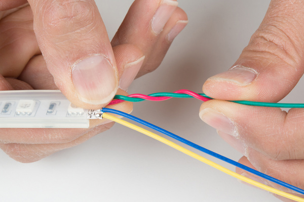
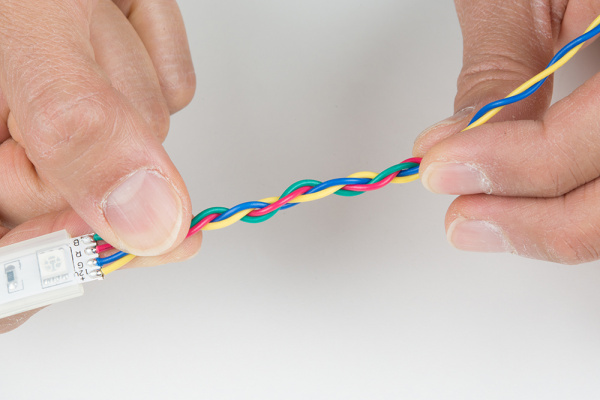
The connection to the pads needed to be secure so I decided to braid the wires together to manage the connections. I was inspired by McCall’s tutorial when completing projects. To braid your wires, twist a pair of wires in a counterclockwise pattern between your index finger and thumb using both hands. I decided to start with the green and red wires.

Wire Management Braiding Counterclockwise 1

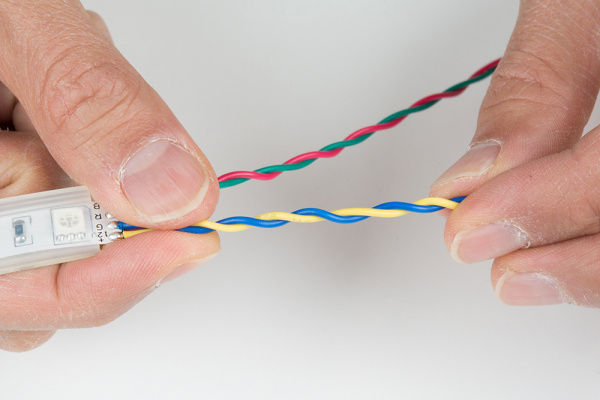
Twist the other pair of wires in a counterclockwise pattern.

Wire Management Braiding Counterclockwise 2

Twist the pairs of wires in a clockwise pattern.

Wire Management Braiding Clockwise

Clean Solder Joints

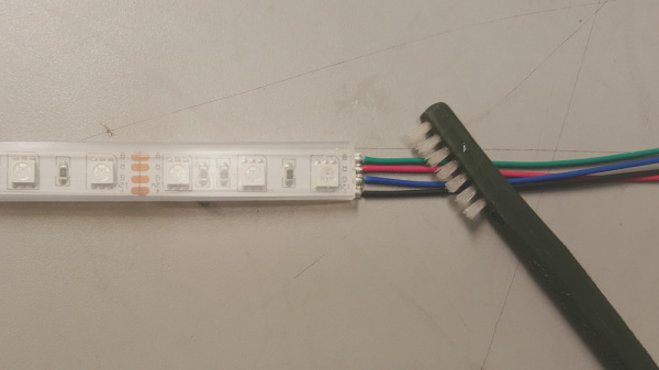
If you were using water soluble flux, clean the solder joints with de-ionized water and a toothbrush. Dry the LED strips thoroughly using compressed air. Luckily, SparkFun has a PCB cleaning room. As an alternative, you could use water from the sink and towels.

Clean Solder Joints

Test LED Strips

Once dry, test the LED strips to make the colors matched and the wires are connected to its respective pads. I decided to use a benchtop power supply set to output about 9V to verify the connection.

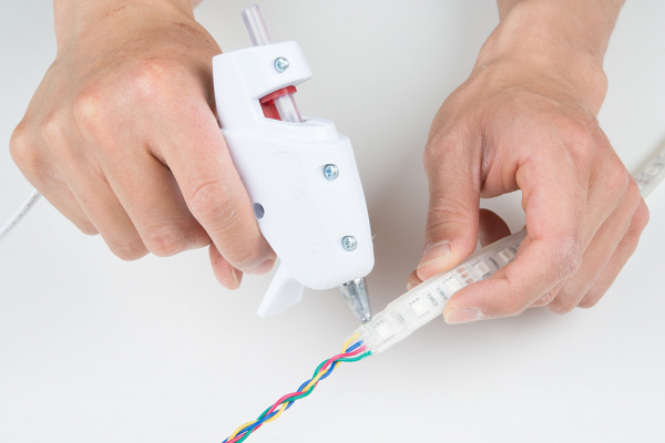
Secure w/ Hot Glue

Add hot glue to the terminals to secure the wires further.

Hot Glue Terminals

Custom LED Strip Adapter

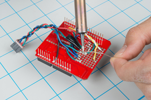
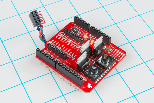
I decided to use a spare XBee shield for the LED strip’s adapter. This also gave me the option of making the circuit wireless if I were to use this in a future project. For the scope of this tutorial, we will be using the XBee shield. You could use a protoshield for more space.

To make the adapter, solder the three n-channel mosfets, three 10kΩ resistors, and two buttons to the prototyping area based on the Fritzing circuit shown earlier. The two solder jumpers were that were connected to the logic level converters and the associated pins were removed. With very little room left, wires were extended out of the bottom of the shield using female headers and prototyping board. Again, the board was clean and tested before moving further.

Capacitive Touch Sensor and Transistor

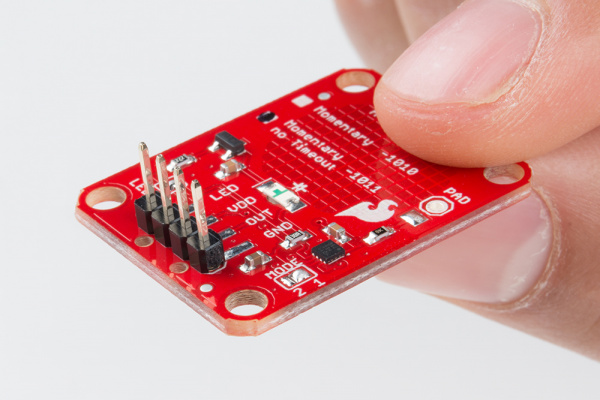
Solder the AT42QT1011 capacitive touch breakout with the longer ends facing the component side. At this point, there was not a lot of room left on the board. Therefore, a mini-breadboard, jumper wires, npn transistor, and 330Ω resistor was need to connect it to the rest of the circuit for initial testing.

Headers Soldered AT42QT1011 capacitive touch breakout

Example Code

Note: This example assumes you are using the latest version of the Arduino IDE on your desktop. If this is your first time using Arduino, please review our tutorial on installing the Arduino IDE.

Download the example code to read the capacitive touch sensor and trigger the LED strip’s color. Just make sure to select the correct COM port and upload with the correct board definition when uploading.

Interactive 3D Printed Lit Diamond Prop GitHub Repo

Enclosure

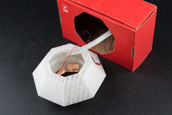
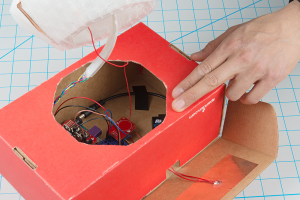
To secure the electronics, a cardboard enclosure was made to house the electronics. I considered using just the diamond holder but the space was limited. Grab a cardboard box and cut a hole in the shape of the holder’s bottom.

Cut Enclosure in the shape of the bottom of the diamond holder

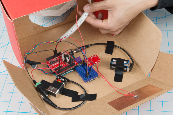
Placed the electronics in the enclosure and secure using electrical tape. This would also be a good time to tape the diamond holder down.

Circuit secured to bottom of cardboard box with electrical tape

Cut an additional hole for the wires leading to the copper tape electrode.

Hole for copper tape's wire

External Electrodes

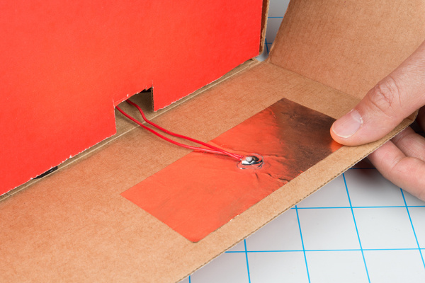
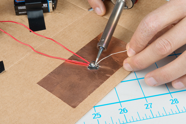
Now that we have an enclosure, the finishing touches can be added to the prop. Cut out a strip of 2" copper tape and solder two pieces of wire to it. Make sure the wire is long enough to extend the capacitive touch sensor’s pin labeled “PAD” to the circuit’s enclosure and to the top of the diamond holder. Solder the other end of the wire to the capacitive touch sensor. Remove the backing and stick the copper tape to the inside wall of the enclosure.

Side Electrode

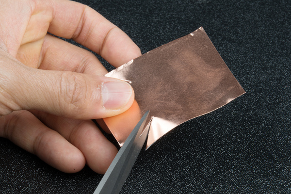
To distinguish the diamond and the holder, copper tape was also added to the top of the holder. Cut out a another piece of the 2" copper tape. Then cut into the tape to match the inside of the holder’s edge.

Cut Copper Tape to Match Holder's Edge

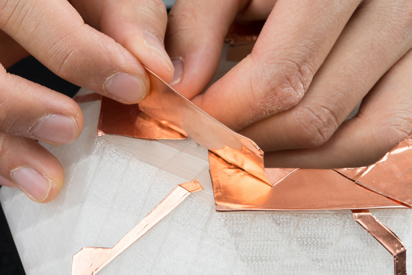
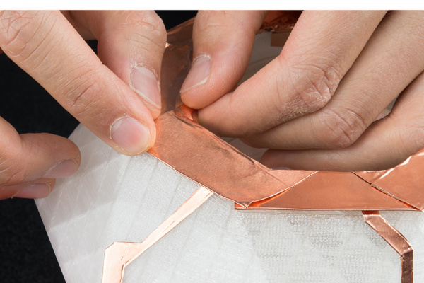
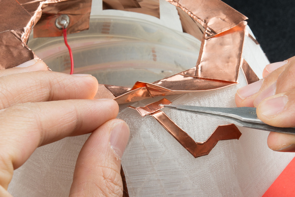
Remove the backing and attach the trapezoid section of the tape to the holder. Then fold the rest of the copper tape in half so that the conductive top side is able to conduct on the top and bottom. Then lay the copper tape flat. Repeat for each edge of the diamond until you have one side left.

With one side left, solder the second wire to extend the capacitive touch sensor’s pad to the trapezoid section. Pull the wire up through the enclosure and holder. Attach the copper tape to the final edge.

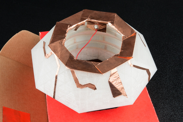
Finished Diamond Holder with Copper Tape Electrodes for Capacitive Touch Sensing

Functional Art

To blend the copper tape on the holder, I decided to add copper tape on the sides of a diamond. This is an optional step but it helped to distinguish the diamond’s holder from the diamond itself. I decided to use the RedBoard’s traces as a guide. Using the board layout files (with layers 16, 22, and 51 turned off), I was able to print out the top layer out. The angles from the traces helped as a guide when manually cutting. Manually cutting holes for vias was considered but was left out of the design.

RedBoard v22 Top Layer (PDF)

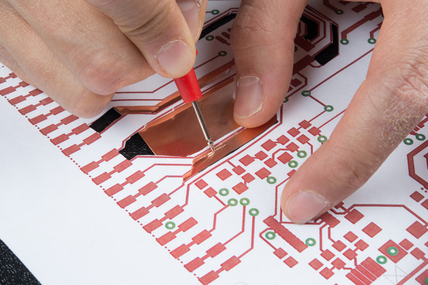
Print out the file and cut out holes loosely based on the RedBoard's layout to make a stencil. Make sure that the traces are no less than ¼ of an inch. Trace the outline with a semi-sharp tip. I used a multimeter prob tip to create a loose outline of the a few different traces.

Trace outline of a trace using the board

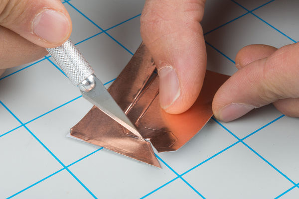
Carefully cut with hobby knife and ruler on a cutting board.

Manually Cut Copper Tape into Traces

Using a small piece of 5mm conductive adhesive tape, I made a loop with the conductive adhesive on the outside and stuck it between each layer of copper to ensure that each piece was conducting.

Add conductive adhesive copper tape between layers to conduct

Stress Testing in the Field

Arming the Diamond Prop

Here’s a demo of how quickly I was able to power up and test the prop before the performance.

Triggering the Diamond Prop

There were a few methods of triggering the LED’s color. My students were instructed to touch the top of the holder to trigger the red color in the middle of the piece. However, there were several other ways to change the color in case anything happened. Here’s a quick demo.

Rehearsals

The instructions were simple enough for my students to understand and the circuit turned out well for the rehearsals.

Show Time!

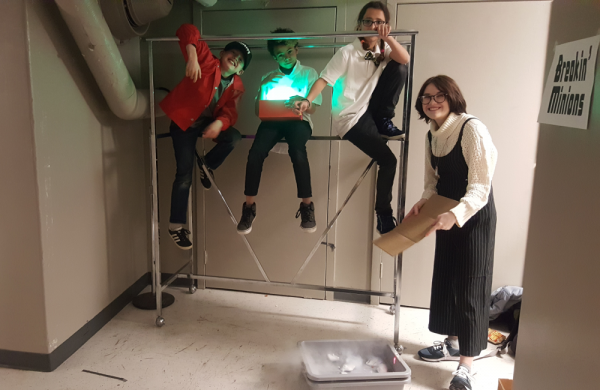
When it came time for the show, I had my handy multimeter, scissors, electrical tape, and backup 9V batteries just in case I needed to troubleshoot. However, the only issue that I ran into was not caused by the prop. The stage manager indicated that the fog from a fog machine could cause the fire alarm to go off. As an alternative, I found that dry ice and water seemed to work as a replacement. Here’s a picture of the team after they went on!

Backstage with the 3D Printed Diamond

Making It Better

There’s always room for improvement. After the project was completed, I realized that the prop could improved. Below are a list of possible upgrades and improvements that could be implemented for future builds.

  • Conductive Adhesive 2" Copper Tape - Initially, I had regular copper tape in my parts bin. I did not realize there was a conductive adhesive until after the electrodes were attached to the diamond holder. Starting with the conductive adhesive 2" roll would have been better to start with.
  • Jumper Wires - After soldering and taping copper tape to the enclosure, the wires seemed to be in the way when I needed to troubleshoot the circuit. Adding M/F jumper wires to connect and disconnect the capacitive touch sensor and enclosure would help make the project modular.
  • Another Protoboard - To secure the connections better, I would have used another prototyping board (like the solderable bredabord to solder all the connections to a instead of having the capacitive touch sensor on a separate mini-breadboard.
  • Switch - Opening the enclosure to plug in the batteries and then closing it was not too bad. Adding two latching power switches between the batteries would make it less tedious.

Resources and Going Further

For more information related to the project, check out the resources below:

Need some inspiration for your next project? Check out some of these related tutorials:

Prototype Wearable LED Dance Harness

A project tutorial to add an extra effect for dancers performing a choreographed piece. The harness can be added quickly under a costume.

Vox Imperium: Stormtrooper Voice Changer

Add some flair to your Imperial uniform by changing your voice using a Teensy 3.2 and Prop Shield.

TeensyView Hookup Guide

A guide to using the TeensyView OLED board to display text and graphics.

Or check out some of these blog posts for ideas:


learn.sparkfun.com | CC BY-SA 3.0 | SparkFun Electronics | Niwot, Colorado

Interactive 3D Printed LED Diamond Prop

$
0
0

Interactive 3D Printed LED Diamond Prop a learn.sparkfun.com tutorial

Available online at: http://sfe.io/t762

Introduction

My students had a dance performance with the theme “Night at the Movies.” I decided to choose a story based on “The Diamond” episode from the old Mission: Impossible television show. To make it fun for the kids and convey the story better to the audience, I decided to build an interactive 3D printed diamond. In this tutorial, you will learn how to 3D print a model and embed electronics in a theatrical prop.

Capacitive Touch 3D Printed Lit LED Diamond Prop

Required Materials

To follow along with this project tutorial, you will need the following materials. You may not need everything though depending on what you have. Add it to your cart, read through the guide, and adjust the cart as necessary.

Tools

You will need a soldering tools, a 3D printer, and a hobby knife.

TAZ 6 3D Printer

TOL-13880
$2,499.95
2
Solder Lead Free - 100-gram Spool

TOL-09325
$7.95
7
Weller WLC100 Soldering Station

TOL-14228
$44.95
Hobby Knife

TOL-09200
$2.95
2

You will also need:

Suggested Reading

If you aren’t familiar with the following concepts, we recommend checking out these tutorials before continuing.

How to Power a Project

A tutorial to help figure out the power requirements of your project.

Installing Arduino IDE

A step-by-step guide to installing and testing the Arduino software on Windows, Mac, and Linux.

Resistors

A tutorial on all things resistors. What is a resistor, how do they behave in parallel/series, decoding the resistor color codes, and resistor applications.

Transistors

A crash course in bi-polar junction transistors. Learn how transistors work and in which circuits we use them.

AT42QT101X Capacitive Touch Breakout Hookup Guide

Learn how to use the simple SparkFun AT42QT1010 and AT42QT1011 capacitive touch breakout boards.

3D Print It

I do not have much experience with 3D printing and modeling complex shapes. Luckily, there were a few models of diamonds listed online that I found to save on time. After browsing Thingiverse, the model that I found appealing was “Oopee’s” diamond lampshade. Head over to the thing and download to print the model of your size.

Thingiverse: Diamond Lampshade

Printing a medium size diamond was sufficient and easy to see on stage as a prop. Caution is advised for printing large scale models due to time and material used.

A Small World, After All?

To start, I printed a small scale version of the diamond lampshade in Cura to see how it would look. The diamond on the bottom left shows the first print of the diamond against the larger prints. Satisfied with the small print. I decided to go bigger!

Test print of small model relative to larger models

Big Trouble in Little… Nozzle

I decided to go big and start printing the diamond. Unfortunately, I ran into an issue once the print started. The 3D printer's extruder kept getting clogged causing the print to fail. I tried using a needle to clean the nozzle and manually feeding more material in the extruder. This fixed the problem temporarily but the issue kept coming up.

3D Print Fails

Doing a search online and inspecting the setup, there were a few possible reasons why this might have been happening:

  • incorrect idler tension
  • speed of the print
  • poor quality filament
  • filament tangled in spool
  • clogged extruder

A clogged extruder seemed to be a plausible explanation of what was going on. Checking in with someone more knowledgeable about 3D printing at SparkFun, I headed over to a mechanical engineer for advice and showed him a few of the stripped filaments as shown below.

stripped filaments

He was able to confirm my assumption. With the technical support's 3D printer being used communally, he explained that the clogged extruder was probably due to either:

  • impurities from poor quality filament (as stated above)
  • changing filament material (PLA to ABS)

Acetone Bath

So how would you fix the clogged extruder? An acetone bath! This was a last resort considering my previous efforts had failed. After removing the tool head from the Lulzbot 3D printer, we carefully removed the hot end's nozzle using some pliers. And by careful, we had to avoid breaking the thermistor attached to the hot end. Once removed, a glass jar was filled just enough to submerge the nozzle tip in acetone and cleaned with a Q-tip over the course of 2 days.

Insufficient Filament and Recycling a Failed Print

While the nozzle was being cleaned, our mechanical engineer was kind enough to allow me to use the mechanical engineering's 3D printer. Off I went to print the big diamond. However, I ran into yet another problem. I did not have enough material! I was too ambitious and did not keep track of the amount of material I had available. 30 hours into the print, I ran out of material as you can see from the image below. While the print failed, I decided to recycle the failed print by making it into a diamond holder.

Filed Print Again

A Happy Medium

Success! On my 10th attempt with a replenished supply of clear filament, I was able to successfully print a diamond. I found a happy medium of printing a diamond. After learning some lessons from the failed prints, I reduced the amount of material used between the walls and reduced the size of the model to a smaller size. Confident in the print, I printed another diamond slightly larger.

Medium

Understanding Your Circuit

Circuit Diagram

Check out the circuit diagram below to see how everything is connected.

Interactive 3D Printed Lit Diamond Prop with Capacitive Touch Sensing Fritzing Circuit

Having trouble seeing the circuit? Click the image for a closer look.

Remote Power

During rehearsals, the prop was initially powered by a 12V wall adapter. It was bulky and not ideal for quick set changes between pieces. Therefore, I decided make it portable using a 9V battery to power the LED strip and controller.

After testing, I noticed that the 9V battery connected to the Arduino's microcontroller not sufficient enough for the LED strip. The LED strip was not bright enough or would display the wrong color.To remedy this, a second 9V battery was attached to the LED strip. Ground was connected to both batteries for reference.

Controlling the LEDs

Since the non-addressable RGB LED strip operate at a higher voltage, a transistor was needed to prevent damage to the microcontroller. A pull-down resistor was also needed so that the Arduino would not have a floating pin. Each color required one n-channel mosfet and one 10kΩ resistor.

Momentary Button to Capacitive Touch Sensing

Initial testing included momentary push buttons with code utilizing the pull-up resistors on the digital pins. One button (connected to pin 2 with a white wire) was used to adjust the color while the other (connected to pin 3 with a yellow wire) was used to change the pattern. The buttons were left on the board to troubleshoot connections.

Eventually, the button to trigger the color was replaced with a capacitive touch sensor and external electrodes. The Arduino had issues reading the capacitive touch sensor’s “OUT” pin by itself so a small npn transistor was added to trigger the button press. A resistor was used as current limiting resistor to the BJT’s base pin.

Hardware Hookup

Non-Addressable RGB LED Strip

With some non-addressable RGB LED strips left over from a previous project, I decided to cut down the remaining strip and solder male jumper wire with male pins. To make it easier, you could use a 4-pin polarized connector and a 1M sealed strip. For the scope of this tutorial, we will be modifying the LED strip and using male jumper wires.

Cut the LED strip at the center of the exposed pads using a diagonal cutter. The dot and dashed line in the image below is where you will need to perform the cut. Make sure to remove part of the silicone tube in order to be able to access the LED strip’s pads.

Cut between the LED Strip's Pads

Cut half of the 12" premium jumper wires and strip the insulation. Then solder the wires to each of the LED strip’s pads.

Solder Wires to LED Strip

The connection to the pads needed to be secure so I decided to braid the wires together to manage the connections. I was inspired by McCall’s tutorial when completing projects. To braid your wires, twist a pair of wires in a counterclockwise pattern between your index finger and thumb using both hands. I decided to start with the green and red wires.

Wire Management Braiding Counterclockwise 1

Twist the other pair of wires in a counterclockwise pattern.

Wire Management Braiding Counterclockwise 2

Twist the pairs of wires in a clockwise pattern.

Wire Management Braiding Clockwise

Clean Solder Joints

If you were using water soluble flux, clean the solder joints with de-ionized water and a toothbrush. Dry the LED strips thoroughly using compressed air. Luckily, SparkFun has a PCB cleaning room. As an alternative, you could use water from the sink and towels.

Clean Solder Joints

Test LED Strips

Once dry, test the LED strips to make the colors matched and the wires are connected to its respective pads. I decided to use a benchtop power supply set to output about 9V to verify the connection.

Secure w/ Hot Glue

Add hot glue to the terminals to secure the wires further.

Hot Glue Terminals

Custom LED Strip Adapter

I decided to use a spare XBee shield for the LED strip’s adapter. This also gave me the option of making the circuit wireless if I were to use this in a future project. For the scope of this tutorial, we will be using the XBee shield. You could use a protoshield for more space.

To make the adapter, solder the three n-channel mosfets, three 10kΩ resistors, and two buttons to the prototyping area based on the Fritzing circuit shown earlier. The two solder jumpers were that were connected to the logic level converters and the associated pins were removed. With very little room left, wires were extended out of the bottom of the shield using female headers and prototyping board. Again, the board was clean and tested before moving further.

Capacitive Touch Sensor and Transistor

Solder the AT42QT1011 capacitive touch breakout with the longer ends facing the component side. At this point, there was not a lot of room left on the board. Therefore, a mini-breadboard, jumper wires, npn transistor, and 330Ω resistor was need to connect it to the rest of the circuit for initial testing.

Headers Soldered AT42QT1011 capacitive touch breakout

Example Code

Note: This example assumes you are using the latest version of the Arduino IDE on your desktop. If this is your first time using Arduino, please review our tutorial on installing the Arduino IDE.

Download the example code to read the capacitive touch sensor and trigger the LED strip’s color. Just make sure to select the correct COM port and upload with the correct board definition when uploading.

Interactive 3D Printed Lit Diamond Prop GitHub Repo

Enclosure

To secure the electronics, a cardboard enclosure was made to house the electronics. I considered using just the diamond holder but the space was limited. Grab a cardboard box and cut a hole in the shape of the holder’s bottom.

Cut Enclosure in the shape of the bottom of the diamond holder

Placed the electronics in the enclosure and secure using electrical tape. This would also be a good time to tape the diamond holder down.

Circuit secured to bottom of cardboard box with electrical tape

Cut an additional hole for the wires leading to the copper tape electrode.

Hole for copper tape's wire

External Electrodes

Now that we have an enclosure, the finishing touches can be added to the prop. Cut out a strip of 2" copper tape and solder two pieces of wire to it. Make sure the wire is long enough to extend the capacitive touch sensor’s pin labeled “PAD” to the circuit’s enclosure and to the top of the diamond holder. Solder the other end of the wire to the capacitive touch sensor. Remove the backing and stick the copper tape to the inside wall of the enclosure.

Side Electrode

To distinguish the diamond and the holder, copper tape was also added to the top of the holder. Cut out a another piece of the 2" copper tape. Then cut into the tape to match the inside of the holder’s edge.

Cut Copper Tape to Match Holder's Edge

Remove the backing and attach the trapezoid section of the tape to the holder. Then fold the rest of the copper tape in half so that the conductive top side is able to conduct on the top and bottom. Then lay the copper tape flat. Repeat for each edge of the diamond until you have one side left.

With one side left, solder the second wire to extend the capacitive touch sensor’s pad to the trapezoid section. Pull the wire up through the enclosure and holder. Attach the copper tape to the final edge.

Finished Diamond Holder with Copper Tape Electrodes for Capacitive Touch Sensing

Functional Art

To blend the copper tape on the holder, I decided to add copper tape on the sides of a diamond. This is an optional step but it helped to distinguish the diamond’s holder from the diamond itself. I decided to use the RedBoard’s traces as a guide. Using the board layout files (with layers 16, 22, and 51 turned off), I was able to print out the top layer out. The angles from the traces helped as a guide when manually cutting. Manually cutting holes for vias was considered but was left out of the design.

RedBoard v22 Top Layer (PDF)

Print out the file and cut out holes loosely based on the RedBoard's layout to make a stencil. Make sure that the traces are no less than ¼ of an inch. Trace the outline with a semi-sharp tip. I used a multimeter prob tip to create a loose outline of the a few different traces.

Trace outline of a trace using the board

Carefully cut with hobby knife and ruler on a cutting board.

Manually Cut Copper Tape into Traces

Using a small piece of 5mm conductive adhesive tape, I made a loop with the conductive adhesive on the outside and stuck it between each layer of copper to ensure that each piece was conducting.

Add conductive adhesive copper tape between layers to conduct

Stress Testing in the Field

Arming the Diamond Prop

Here’s a demo of how quickly I was able to power up and test the prop before the performance.

Triggering the Diamond Prop

There were a few methods of triggering the LED’s color. My students were instructed to touch the top of the holder to trigger the red color in the middle of the piece. However, there were several other ways to change the color in case anything happened. Here’s a quick demo.

Rehearsals

The instructions were simple enough for my students to understand and the circuit turned out well for the rehearsals.

Show Time!

When it came time for the show, I had my handy multimeter, scissors, electrical tape, and backup 9V batteries just in case I needed to troubleshoot. However, the only issue that I ran into was not caused by the prop. The stage manager indicated that the fog from a fog machine could cause the fire alarm to go off. As an alternative, I found that dry ice and water seemed to work as a replacement. Here’s a picture of the team after they went on!

Backstage with the 3D Printed Diamond

Making It Better

There’s always room for improvement. After the project was completed, I realized that the prop could improved. Below are a list of possible upgrades and improvements that could be implemented for future builds.

  • Conductive Adhesive 2" Copper Tape - Initially, I had regular copper tape in my parts bin. I did not realize there was a conductive adhesive until after the electrodes were attached to the diamond holder. Starting with the conductive adhesive 2" roll would have been better to start with.
  • Jumper Wires - After soldering and taping copper tape to the enclosure, the wires seemed to be in the way when I needed to troubleshoot the circuit. Adding M/F jumper wires to connect and disconnect the capacitive touch sensor and enclosure would help make the project modular.
  • Another Protoboard - To secure the connections better, I would have used another prototyping board (like the solderable bredabord to solder all the connections to a instead of having the capacitive touch sensor on a separate mini-breadboard.
  • Switch - Opening the enclosure to plug in the batteries and then closing it was not too bad. Adding two latching power switches between the batteries would make it less tedious.

Resources and Going Further

For more information related to the project, check out the resources below:

Need some inspiration for your next project? Check out some of these related tutorials:

Prototype Wearable LED Dance Harness

A project tutorial to add an extra effect for dancers performing a choreographed piece. The harness can be added quickly under a costume.

Vox Imperium: Stormtrooper Voice Changer

Add some flair to your Imperial uniform by changing your voice using a Teensy 3.2 and Prop Shield.

TeensyView Hookup Guide

A guide to using the TeensyView OLED board to display text and graphics.

Or check out some of these blog posts for ideas:


learn.sparkfun.com | CC BY-SA 3.0 | SparkFun Electronics | Niwot, Colorado
Addressable LED Neon Flex Rope Hookup Guide

$
0
0

Addressable LED Neon Flex Rope Hookup Guide a learn.sparkfun.com tutorial

Available online at: http://sfe.io/t763

Introduction

The addressable LED Neon Flex Rope adds cool lighting effects for outdoor and indoor uses including in hallways and stairs, holiday lighting and more! In this hookup guide, you will learn how to connect, power, and control the LED segments with an Arduino.

LED Neon Flex Rope

COM-14555
$39.95
2

Required Materials

To follow along with this project tutorial, you will need the following materials. You may not need everything though depending on what you have. Add it to your cart, read through the guide, and adjust the cart as necessary. If you are just looking at powering up the LED neon flex rope and using its demo mode, you will need the following.

DC Barrel Jack Adapter - Female

PRT-10288
$2.95
1
Power Cable - 7A IEC C13

TOL-11299
1
Power Supply - 24V (5A)

TOL-13758
$24.95

To test and control the segments, you will need the following materials listed below.

SparkFun RedBoard - Programmed with Arduino

DEV-13975
$19.95
26
SparkFun USB Mini-B Cable - 6 Foot

CAB-11301
$3.95
2
Alligator Clip with Pigtail (10 Pack)

CAB-14303
$6.95
2
Hook-up Wire - Black (22 AWG)

PRT-08022
$2.50
1
USB Wall Charger - 5V, 1A (Black)

TOL-11456
$3.95
2

Tools

Depending on the application, you may need a soldering iron, solder, and general soldering accessories for a more secure connection. Otherwise, the following tools will suffice for hooking up and testing.

Wire Strippers - 30AWG (Hakko)

TOL-12630
$9.95
3
SparkFun Mini Screwdriver

TOL-09146
$0.95
2

Suggested Reading

If you aren’t familiar with the following concepts, we recommend checking out these tutorials before continuing.

What is an Arduino?

What is this 'Arduino' thing anyway?

Installing Arduino IDE

A step-by-step guide to installing and testing the Arduino software on Windows, Mac, and Linux.

Hardware Overview

The LED Neon Flex Rope uses the UCS1903 chipset and LEDs. The electronics are sealed in a waterproof IP65 silicone housing and diffuses the light emitting from the LEDs.

Pinout

To power or control the LED neon flex rope, you will need to connect to the female bare wire connector. 24V is required to power the LED Neon flex rope using the wire with the red stripe. The center wire is the data pin when using with a microcontroller. The third wire on the other side is for ground.

LED Neon Flex Rope Pinout

Below lists a hookup table of the pinout for reference.

LED Neon Flex Rope Pinout
Vcc (Red Striped)24V
DAT (Middle)Data
GND (Side)Ground

Hardware Hookup w/ Power Only

When powering the LED neon flex rope with only power, it will display a demo. Insert the 3-prong power cable into the 24V power supply. Then make the following connections with using a female DC barrel jack adapter.

24V Power Supply Female DC Barrel Jack Adapter LED Neon Flex Rope Pinout
Center Positive+Vcc (Red Striped) = 24V
Clear (Middle) = DAT
GND-Clear (Side) = GND

Once connected, insert and fasten the adapter to the female bare wire connector into the LED neon flex rope. The setup should look like the image below. Tape was used to insulate the DAT pin since the wire was exposed.

Hardware Hookup with Only Power

Demo Mode

By connecting only to the power pins, the LED Neon Flex Rope will run a demo mode. This can include the rope cycling colors using different patterns. This can include:

  • one solid color
  • pulse and fade
  • alternating between colors
  • each segment incrementally lighting up with one color

Hardware Hookup w/ Arduino

For users that want to control the animations or react to input from a sensor, an Arduino microcontroller can be used to control the LED neon flex rope’s segments. For a quick connection, we will use an alligator clip with pigtail and hookup wire.

Connecting to the DAT Pin

For initial testing, we will be using an alligator clip with pigtail to connect the LED Neon flex’s DAT pin to the software defined control pin on the Arduino. Use the alligator clip to clamp on the DAT pin wire and then connect the other end to D5.

Additional Power Supply and GND Reference

Since the recommended input voltage via the barrel jack for the RedBoard is 15V, an additional power supply is required. For the scope of this tutorial, we will use the mini-USB connector on the Arduino to power the control circuit with 5V. A 5V USB port from a computer can be used during testing. A 5V USB wall adapter can be used when powering the Arduino in a project or installation.

Since we are adding an additional power supply, make sure to ground the LED neon flex rope with the control circuit. Strip a piece of wire. Then connect the “-” on the DC barrel jack adapter to the Arduino’s GND pin. Wrap the wires together to make a more secure connection.

Insert Wire to GND for ReferenceScrew In GND Wires

Hookup Table

Based on the connections described above, here is a hookup table of the connections.

24V Power Supply Female DC Barrel Jack Adapter LED Neon Flex Rope Pinout Arduino 5V Power Supply
Center Positive+Vcc (Red striped) = 24V
5V5V
Clear (middle wire) = DATPin 5 (or whatever is defined)
GND-Clear (side) = GNDGNDGND

The final circuit should look similar to the image below.

LED Neon Flex Rope Controlled by Arduino

Library Overview

Note: This example assumes you are using the latest version of the Arduino IDE on your desktop. If this is your first time using Arduino, please review our tutorial on installing the Arduino IDE. If you have not previously installed an Arduino library, please check out our installation guide.

To control the LED Neon Flex Rope, you could use a 5V Arduino-based microcontroller. You will need to download and install Daniel Garcia’s FastLED library using the library manager. You can also manually install it from the GitHub Repository by downloading the library from the button below.

Download FastLED Library (ZIP) Here

Parameters

When using the FastLED library, certain parameters need to be adjusted to be compatible with the chipset. When using the FastLED library, the LED_TYPE would be defined as the UCS1903 chipset. There are 16 segments per LED Neon Flex Rope to control so the NUM_LEDs is 16. The COLOR_ORDER is BRG so:

red = blue
green = red
blue = green

Example Code

The FastLED library includes a few examples for a variety of addressable LED chipsets to get started. The following examples will demonstrate how to modify the example to use with the UCS1903 chipset. For more information, check out the FastLED Library’s wiki.

FastLED Library Wiki: Chipset Reference

FastLED Blink Modification

For simplicity, lets blink one segment of one LED neon flex rope using the FastLED’s Blink.ino example by following the steps listed below:

  • First adjust the number of LEDs in the strip to 16.
  • Change the DATA_PIN to pin 5.
  • Comment out the CLOCK_PIN and LED arrangement for the neopixel.
  • Uncomment out the LED arrangement for the UCS1903 chipset.
  • Modify the color order by changing RGB to BRG.

Or copy and paste the modified example in an Arduino sketch. After uploading, you should see one segment blink with red.

language:c
/*Modified FastLED Blink.ino Example
 * 
 * Description: This modified example is used to control one segment 
     * of the LED Neon Flex Rope.
 */
#include "FastLED.h"

// How many leds in your strip?
#define NUM_LEDS 16 //# of segments on the LED Neon Flex Rope

// For led chips like Neopixels, which have a data line, ground, and power, you just
// need to define DATA_PIN.  For led chipsets that are SPI based (four wires - data, clock,
// ground, and power), like the LPD8806 define both DATA_PIN and CLOCK_PIN
#define DATA_PIN 5
//#define CLOCK_PIN 13

// Define the array of leds
CRGB leds[NUM_LEDS];

void setup() { 
      // Uncomment/edit one of the following lines for your leds arrangement.
      // FastLED.addLeds<TM1803, DATA_PIN, RGB>(leds, NUM_LEDS);
      // FastLED.addLeds<TM1804, DATA_PIN, RGB>(leds, NUM_LEDS);
      // FastLED.addLeds<TM1809, DATA_PIN, RGB>(leds, NUM_LEDS);
      // FastLED.addLeds<WS2811, DATA_PIN, RGB>(leds, NUM_LEDS);
      // FastLED.addLeds<WS2812, DATA_PIN, RGB>(leds, NUM_LEDS);
      // FastLED.addLeds<WS2812B, DATA_PIN, RGB>(leds, NUM_LEDS);
      //FastLED.addLeds<NEOPIXEL, DATA_PIN>(leds, NUM_LEDS);
      // FastLED.addLeds<APA104, DATA_PIN, RGB>(leds, NUM_LEDS);
      FastLED.addLeds<UCS1903, DATA_PIN, BRG>(leds, NUM_LEDS);
      // FastLED.addLeds<UCS1903B, DATA_PIN, RGB>(leds, NUM_LEDS);
      // FastLED.addLeds<GW6205, DATA_PIN, RGB>(leds, NUM_LEDS);
      // FastLED.addLeds<GW6205_400, DATA_PIN, RGB>(leds, NUM_LEDS);

      // FastLED.addLeds<WS2801, RGB>(leds, NUM_LEDS);
      // FastLED.addLeds<SM16716, RGB>(leds, NUM_LEDS);
      // FastLED.addLeds<LPD8806, RGB>(leds, NUM_LEDS);
      // FastLED.addLeds<P9813, RGB>(leds, NUM_LEDS);
      // FastLED.addLeds<APA102, RGB>(leds, NUM_LEDS);
      // FastLED.addLeds<DOTSTAR, RGB>(leds, NUM_LEDS);

      // FastLED.addLeds<WS2801, DATA_PIN, CLOCK_PIN, RGB>(leds, NUM_LEDS);
      // FastLED.addLeds<SM16716, DATA_PIN, CLOCK_PIN, RGB>(leds, NUM_LEDS);
      // FastLED.addLeds<LPD8806, DATA_PIN, CLOCK_PIN, RGB>(leds, NUM_LEDS);
      // FastLED.addLeds<P9813, DATA_PIN, CLOCK_PIN, RGB>(leds, NUM_LEDS);
      // FastLED.addLeds<APA102, DATA_PIN, CLOCK_PIN, RGB>(leds, NUM_LEDS);
      // FastLED.addLeds<DOTSTAR, DATA_PIN, CLOCK_PIN, RGB>(leds, NUM_LEDS);
}

void loop() { 
  // Turn the LED on, then pause
  leds[0] = CRGB::Red;
  FastLED.show();
  delay(500);
  // Now turn the LED off, then pause
  leds[0] = CRGB::Black;
  FastLED.show();
  delay(500);
}

Blink Each Segment

To control all the segments with control, you would need to address each segment in the array with a color. Write code to address each segment defined in the array and reduce the delay between each blink. Or copy and paste the modified blink example in an Arduino sketch. After uploading, you should see each segment blink red.

language:c
/*Modified FastLED Blink.ino Example
* 
* Description: This modified example is used to control all segments
* of the LED Neon Flex Rope.
*/
#include "FastLED.h"

// How many leds in your strip?
#define NUM_LEDS 16 //# of segments on the LED Neon Flex Rope

// For led chips like Neopixels, which have a data line, ground, and power, you just
// need to define DATA_PIN.  For led chipsets that are SPI based (four wires - data, clock,
// ground, and power), like the LPD8806 define both DATA_PIN and CLOCK_PIN
#define DATA_PIN 5
//#define CLOCK_PIN 13 //not used with UCS1903 chipset

// Define the array of leds
CRGB leds[NUM_LEDS];

void setup() { 
    // Uncomment/edit one of the following lines for your leds arrangement.
    // FastLED.addLeds<TM1803, DATA_PIN, RGB>(leds, NUM_LEDS);
    // FastLED.addLeds<TM1804, DATA_PIN, RGB>(leds, NUM_LEDS);
    // FastLED.addLeds<TM1809, DATA_PIN, RGB>(leds, NUM_LEDS);
    // FastLED.addLeds<WS2811, DATA_PIN, RGB>(leds, NUM_LEDS);
    // FastLED.addLeds<WS2812, DATA_PIN, RGB>(leds, NUM_LEDS);
    // FastLED.addLeds<WS2812B, DATA_PIN, RGB>(leds, NUM_LEDS);
    //FastLED.addLeds<NEOPIXEL, DATA_PIN>(leds, NUM_LEDS);
    // FastLED.addLeds<APA104, DATA_PIN, RGB>(leds, NUM_LEDS);
    FastLED.addLeds<UCS1903, DATA_PIN, BRG>(leds, NUM_LEDS);
    // FastLED.addLeds<UCS1903B, DATA_PIN, RGB>(leds, NUM_LEDS);
    // FastLED.addLeds<GW6205, DATA_PIN, RGB>(leds, NUM_LEDS);
    // FastLED.addLeds<GW6205_400, DATA_PIN, RGB>(leds, NUM_LEDS);

    // FastLED.addLeds<WS2801, RGB>(leds, NUM_LEDS);
    // FastLED.addLeds<SM16716, RGB>(leds, NUM_LEDS);
    // FastLED.addLeds<LPD8806, RGB>(leds, NUM_LEDS);
    // FastLED.addLeds<P9813, RGB>(leds, NUM_LEDS);
    // FastLED.addLeds<APA102, RGB>(leds, NUM_LEDS);
    // FastLED.addLeds<DOTSTAR, RGB>(leds, NUM_LEDS);

    // FastLED.addLeds<WS2801, DATA_PIN, CLOCK_PIN, RGB>(leds, NUM_LEDS);
    // FastLED.addLeds<SM16716, DATA_PIN, CLOCK_PIN, RGB>(leds, NUM_LEDS);
    // FastLED.addLeds<LPD8806, DATA_PIN, CLOCK_PIN, RGB>(leds, NUM_LEDS);
    // FastLED.addLeds<P9813, DATA_PIN, CLOCK_PIN, RGB>(leds, NUM_LEDS);
    // FastLED.addLeds<APA102, DATA_PIN, CLOCK_PIN, RGB>(leds, NUM_LEDS);
    // FastLED.addLeds<DOTSTAR, DATA_PIN, CLOCK_PIN, RGB>(leds, NUM_LEDS);
}

void loop() {
// Turn the LED on, then pause
leds[0] = CRGB::Red;
FastLED.show();
delay(250);
// Now turn the LED off, then pause
leds[0] = CRGB::Black;
FastLED.show();
delay(250);

// Turn the LED on, then pause
leds[1] = CRGB::Red;
FastLED.show();
delay(250);
// Now turn the LED off, then pause
leds[1] = CRGB::Black;
FastLED.show();
delay(250);

// Turn the LED on, then pause
leds[2] = CRGB::Red;
FastLED.show();
delay(250);
// Now turn the LED off, then pause
leds[2] = CRGB::Black;
FastLED.show();
delay(250);

// Turn the LED on, then pause
leds[3] = CRGB::Red;
FastLED.show();
delay(250);
// Now turn the LED off, then pause
leds[3] = CRGB::Black;
FastLED.show();
delay(250);

// Turn the LED on, then pause
leds[4] = CRGB::Red;
FastLED.show();
delay(250);
// Now turn the LED off, then pause
leds[4] = CRGB::Black;
FastLED.show();
delay(250);

// Turn the LED on, then pause
leds[5] = CRGB::Red;
FastLED.show();
delay(250);
// Now turn the LED off, then pause
leds[5] = CRGB::Black;
FastLED.show();
delay(250);

// Turn the LED on, then pause
leds[6] = CRGB::Red;
FastLED.show();
delay(250);
// Now turn the LED off, then pause
leds[6] = CRGB::Black;
FastLED.show();
delay(250);


// Turn the LED on, then pause
leds[7] = CRGB::Red;
FastLED.show();
delay(250);
// Now turn the LED off, then pause
leds[7] = CRGB::Black;
FastLED.show();
delay(250);

// Turn the LED on, then pause
leds[8] = CRGB::Red;
FastLED.show();
delay(250);
// Now turn the LED off, then pause
leds[8] = CRGB::Black;
FastLED.show();
delay(250);

// Turn the LED on, then pause
leds[9] = CRGB::Red;
FastLED.show();
delay(250);
// Now turn the LED off, then pause
leds[9] = CRGB::Black;
FastLED.show();
delay(250);

// Turn the LED on, then pause
leds[10] = CRGB::Red;
FastLED.show();
delay(250);
// Now turn the LED off, then pause
leds[10] = CRGB::Black;
FastLED.show();
delay(250);

// Turn the LED on, then pause
leds[11] = CRGB::Red;
FastLED.show();
delay(250);
// Now turn the LED off, then pause
leds[11] = CRGB::Black;
FastLED.show();
delay(250);

// Turn the LED on, then pause
leds[12] = CRGB::Red;
FastLED.show();
delay(250);
// Now turn the LED off, then pause
leds[12] = CRGB::Black;
FastLED.show();
delay(250);

// Turn the LED on, then pause
leds[13] = CRGB::Red;
FastLED.show();
delay(250);
// Now turn the LED off, then pause
leds[13] = CRGB::Black;
FastLED.show();
delay(250);

// Turn the LED on, then pause
leds[14] = CRGB::Red;
FastLED.show();
delay(250);
// Now turn the LED off, then pause
leds[14] = CRGB::Black;
FastLED.show();
delay(250);

// Turn the LED on, then pause
leds[15] = CRGB::Red;
FastLED.show();
delay(250);
// Now turn the LED off, then pause
leds[15] = CRGB::Black;
FastLED.show();
delay(250);
}

Color Pallete

Let's try modifying one more example from the Fast LED library to add the color pallete animation to the LED Neon Flex Rope light. After uploading, you should see the patterns cycling.

language:c
/*Modified FastLED ColorPalette.ino Example
* 
* Description: This modified ColorPalette example is used to control all segments
* of the LED Neon Flex Rope.
*/

#include <FastLED.h>

#define LED_PIN     5
#define NUM_LEDS    16
#define BRIGHTNESS  255
#define LED_TYPE    UCS1903
#define COLOR_ORDER BRG
CRGB leds[NUM_LEDS];

#define UPDATES_PER_SECOND 100

// This example shows several ways to set up and use 'palettes' of colors
// with FastLED.
//
// These compact palettes provide an easy way to re-colorize your
// animation on the fly, quickly, easily, and with low overhead.
//
// USING palettes is MUCH simpler in practice than in theory, so first just
// run this sketch, and watch the pretty lights as you then read through
// the code.  Although this sketch has eight (or more) different color schemes,
// the entire sketch compiles down to about 6.5K on AVR.
//
// FastLED provides a few pre-configured color palettes, and makes it
// extremely easy to make up your own color schemes with palettes.
//
// Some notes on the more abstract 'theory and practice' of
// FastLED compact palettes are at the bottom of this file.

CRGBPalette16 currentPalette;
TBlendType    currentBlending;

extern CRGBPalette16 myRedWhiteBluePalette;
extern const TProgmemPalette16 myRedWhiteBluePalette_p PROGMEM;


void setup() {
    delay( 3000 ); // power-up safety delay
    FastLED.addLeds<LED_TYPE, LED_PIN, COLOR_ORDER>(leds, NUM_LEDS).setCorrection( TypicalLEDStrip );
    FastLED.setBrightness(  BRIGHTNESS );

    currentPalette = RainbowColors_p;
    currentBlending = LINEARBLEND;
}


void loop()
{
    ChangePalettePeriodically();

    static uint8_t startIndex = 0;
    startIndex = startIndex + 1; /* motion speed */

    FillLEDsFromPaletteColors( startIndex);

    FastLED.show();
    FastLED.delay(1000 / UPDATES_PER_SECOND);
}

void FillLEDsFromPaletteColors( uint8_t colorIndex)
{
    uint8_t brightness = 255;

    for( int i = 0; i < NUM_LEDS; i++) {
        leds[i] = ColorFromPalette( currentPalette, colorIndex, brightness, currentBlending);
        colorIndex += 3;
    }
}


// There are several different palettes of colors demonstrated here.
//
// FastLED provides several 'preset' palettes: RainbowColors_p, RainbowStripeColors_p,
// OceanColors_p, CloudColors_p, LavaColors_p, ForestColors_p, and PartyColors_p.
//
// Additionally, you can manually define your own color palettes, or you can write
// code that creates color palettes on the fly.  All are shown here.

void ChangePalettePeriodically()
{
    uint8_t secondHand = (millis() / 1000) % 60;
    static uint8_t lastSecond = 99;

    if( lastSecond != secondHand) {
        lastSecond = secondHand;
        if( secondHand ==  0)  { currentPalette = RainbowColors_p;         currentBlending = LINEARBLEND; }
        if( secondHand == 10)  { currentPalette = RainbowStripeColors_p;   currentBlending = NOBLEND;  }
        if( secondHand == 15)  { currentPalette = RainbowStripeColors_p;   currentBlending = LINEARBLEND; }
        if( secondHand == 20)  { SetupPurpleAndGreenPalette();             currentBlending = LINEARBLEND; }
        if( secondHand == 25)  { SetupTotallyRandomPalette();              currentBlending = LINEARBLEND; }
        if( secondHand == 30)  { SetupBlackAndWhiteStripedPalette();       currentBlending = NOBLEND; }
        if( secondHand == 35)  { SetupBlackAndWhiteStripedPalette();       currentBlending = LINEARBLEND; }
        if( secondHand == 40)  { currentPalette = CloudColors_p;           currentBlending = LINEARBLEND; }
        if( secondHand == 45)  { currentPalette = PartyColors_p;           currentBlending = LINEARBLEND; }
        if( secondHand == 50)  { currentPalette = myRedWhiteBluePalette_p; currentBlending = NOBLEND;  }
        if( secondHand == 55)  { currentPalette = myRedWhiteBluePalette_p; currentBlending = LINEARBLEND; }
    }
}

// This function fills the palette with totally random colors.
void SetupTotallyRandomPalette()
{
    for( int i = 0; i < 16; i++) {
        currentPalette[i] = CHSV( random8(), 255, random8());
    }
}

// This function sets up a palette of black and white stripes,
// using code.  Since the palette is effectively an array of
// sixteen CRGB colors, the various fill_* functions can be used
// to set them up.
void SetupBlackAndWhiteStripedPalette()
{
    // 'black out' all 16 palette entries...
    fill_solid( currentPalette, 16, CRGB::Black);
    // and set every fourth one to white.
    currentPalette[0] = CRGB::White;
    currentPalette[4] = CRGB::White;
    currentPalette[8] = CRGB::White;
    currentPalette[12] = CRGB::White;

}

// This function sets up a palette of purple and green stripes.
void SetupPurpleAndGreenPalette()
{
    CRGB purple = CHSV( HUE_PURPLE, 255, 255);
    CRGB green  = CHSV( HUE_GREEN, 255, 255);
    CRGB black  = CRGB::Black;

    currentPalette = CRGBPalette16(
                                green,  green,  black,  black,
                                purple, purple, black,  black,
                                green,  green,  black,  black,
                                purple, purple, black,  black );
}


// This example shows how to set up a static color palette
// which is stored in PROGMEM (flash), which is almost always more
// plentiful than RAM.  A static PROGMEM palette like this
// takes up 64 bytes of flash.
const TProgmemPalette16 myRedWhiteBluePalette_p PROGMEM =
{
    CRGB::Red,
    CRGB::Gray, // 'white' is too bright compared to red and blue
    CRGB::Blue,
    CRGB::Black,

    CRGB::Red,
    CRGB::Gray,
    CRGB::Blue,
    CRGB::Black,

    CRGB::Red,
    CRGB::Red,
    CRGB::Gray,
    CRGB::Gray,
    CRGB::Blue,
    CRGB::Blue,
    CRGB::Black,
    CRGB::Black
};


// Additionl notes on FastLED compact palettes:
//
// Normally, in computer graphics, the palette (or "color lookup table")
// has 256 entries, each containing a specific 24-bit RGB color.  You can then
// index into the color palette using a simple 8-bit (one byte) value.
// A 256-entry color palette takes up 768 bytes of RAM, which on Arduino
// is quite possibly "too many" bytes.
//
// FastLED does offer traditional 256-element palettes, for setups that
// can afford the 768-byte cost in RAM.
//
// However, FastLED also offers a compact alternative.  FastLED offers
// palettes that store 16 distinct entries, but can be accessed AS IF
// they actually have 256 entries; this is accomplished by interpolating
// between the 16 explicit entries to create fifteen intermediate palette
// entries between each pair.
//
// So for example, if you set the first two explicit entries of a compact 
// palette to Green (0,255,0) and Blue (0,0,255), and then retrieved 
// the first sixteen entries from the virtual palette (of 256), you'd get
// Green, followed by a smooth gradient from green-to-blue, and then Blue.

Resources and Going Further

Now that you’ve successfully got your LED Neon Flex Rope up and running, it’s time to incorporate it into your own project!

For more information, check out the resources below:

Need some inspiration for your next project? Check out some of these related tutorials:

Addressable RGB LED Music and Sound Visualizer

Use an Arduino and the SparkFun Sound Detector to create visualizations on Addressable RGB LED strips.
New!

Using Artnet DMX and the ESP32 to Drive Pixels

In this tutorial, we'll find out how to use Resolume Arena, a popular video jockey software, to control custom-made ArtNet DMX fixtures.
New!

Craft a Holiday Greeting with Love to Code

Craft your own paper circuit holiday greeting using the LEDs, a Chibi Chip, Love to Code!
New!

Interactive 3D Printed LED Diamond Prop

In this tutorial, we will learn about how to create an interactive theatrical prop for a performance by 3D printing a translucent diamond prop using a non-addressable RGB LED strip and AT42QT1011 capacitive touch sensing.

learn.sparkfun.com | CC BY-SA 3.0 | SparkFun Electronics | Niwot, Colorado

LilyPad Tri-Color LED Hookup Guide

$
0
0

LilyPad Tri-Color LED Hookup Guide a learn.sparkfun.com tutorial

Available online at: http://sfe.io/t725

Introduction

The LilyPad Tri-Color LED is a specialty board that can produce a variety of colors. On the board is an RGB (red-green-blue) LED, made of three tiny LEDs connected together. Each of the colors in the RGB LED are connected to one of the sew tabs on the board labeled as R, G, and B.

LilyPad Tri-Color LED

DEV-08467
$2.95
2

To follow along with the code examples, we recommend:

Suggested Reading

To add this LED to a project, you should be comfortable sewing with conductive thread and uploading code to your LilyPad Arduino (for the programming examples). Here are some tutorials to review before working with this part:

What is a Circuit?

Every electrical project starts with a circuit. Don't know what a circuit is? We're here to help.

Light

Light is a useful tool for the electrical engineer. Understanding how light relates to electronics is a fundamental skill for many projects.

Insulation Techniques for e-Textiles

Learn a few different ways to protect your conductive thread and LilyPad components in your next wearables project.

LilyPad Basics: E-Sewing

Learn how to use conductive thread with LilyPad components.

Getting Started with LilyPad

An introduction to the LilyPad ecosystem - a set of sewable electronic pieces designed to help you build soft, sewable, interactive e-textile projects.
Note on Common Anode vs Common Cathode

The color channels on this RGB LED are all connected through a common anode (positive) pin. Unlike some other RGB LEDs, this configuration means that to light up the LED you need to ground the individual red, green, and blue LEDs instead of sending them power. For simple circuit hookups, this means you need to connect the R, G, or B sew tabs to ground (-) and in code set them to LOW (for digital output) or 0 (for analog output) to turn them on.


The RGB LED on the tri-color LED has 4 connections: red, green, blue channels, and a common anode pin.
If you look closely you can see the individual LEDs inside the package.

Using in a Simple E-Sewing Project

The tri-color LED doesn’t need to be connected to a microcontroller in order to control it. Here are some examples of using simple circuits to mix colors with the LED.

To experiment with basic color mixing, you can use alligator clips on the tri-color LED’s sew tabs to temporarily connect them to a power source, such as a LilyPad Coin Cell Battery Holder with a coin cell battery. Connect the positive tab (+) to the positive sew tab on the battery holder with a clip, and each color tab R (Red), G (Green), and B (Blue) to the negative tab (-) to connect them. The combination of color sew tabs that are connected to power and illuminated will create a variety of colors.

LilyPad Tri-Color LED connected to three alligator clips and a LilyPad Battery Holder

You can replace these connections with switches or buttons for a simple color mixing circuit. After prototyping and testing a project with the tri-color LED you can replace the connections with conductive thread in your project.

Tri-Color LED stitched with conductive thread to three LilyPad Switches and a LilyPad Battery Holder

Simple color mixing circuit using a LilyPad Switches connected to each color tab of the tri-color LED.

Attaching to a LilyPad Arduino

To follow along with the code examples in this tutorial, connect the tri-color LED to a LilyPad Arduino as shown below. Use alligator clips to temporarily connect the R (Red) tab on the LED to 11, G (Green) to 9, B (Blue) to 10, and (+) to (+). When you are finished prototyping, replace the alligator clips with conductive thread traces for permanent installation in your project.

The numbered labels next to the R, G, and B tabs on the tri-color LED were originally made for the LED's use on the LilyPad Development Board. To make our diagrams easier to follow, and to avoid any potential short circuits in our stitching, we've chosen different tabs than the labels to connect to in the following code examples.

Note: To follow along with the Custom Color Mixing example code, you will need to attach the R, G, and B tabs to a sew tabs on the LilyPad with PWM capabilities.

Attaching the Tri-Color LED to a LilyPad Arduino USB

Additional Board Hookup

If you’d like to use the tri-color LED with the LilyPad ProtoSnap Plus, attach the R, G, and B tabs to the ProtoSnap’s expansion ports. Only port 10 has PWM capabilities, so you will not be able to follow along with the Custom Color Mixing example unless you snap the ProtoSnap Plus apart and connect the tri-color LED directly to tabs on the LilyPad USB Plus.

If using the the pre-wired tri-color LED on the ProtoSnap - LilyPad Development Board, the connection is different than what was explained earlier. R is attached to 9, G is attached to 11, and B is attached to 10. We recommend checking out the LilyPad Development Board Activity Guide for step-by-step examples using this LED.

Basic Color Mixing with Code

Note: This example assumes you are using the latest version of the Arduino IDE on your desktop. If this is your first time using Arduino, please review our tutorial on installing the Arduino IDE.

This example code demonstrates how to display a simple rainbow of colors using the tri-color LED. In order to create colors with the RGB LED, you’ll have to set each of the LEDs within it individually. The combination of light from the LEDs mixed together creates new colors.

Upload the following code to your LilyPad Arduino, making sure to select the correct LilyPad board from the drop down menu below. Choose LilyPad Arduino USB if using a LilyPad Arduino USB. The LilyPad Arduino Simple, LilyPad Arduino, and LilyPad Development Board, and Development Board Simple all use a LilyPad ATmega 328. Select LilyPad USB Plus if following along with the LilyPad ProtoSnap Plus.

Copy and paste the following code into the Arduino IDE and upload it to your LilyPad Arduino.

language:c
/*
LilyPad Tri-Color LED: Basic Color Mixing
SparkFun Electronics
https://www.sparkfun.com/products/8467

Create primary and secondary colors on the tri-color (Red/Green/Blue)
LED connected to a LilyPad Arduino.

Tri-Color LED connections:
* R pin to 11
* G pin to 10
* B pin to 9
* + pin to +


This code is released under the MIT License (http://opensource.org/licenses/MIT)

******************************************************************************/

// This example uses a tri-color, also known as an RGB 
// (Red / Green / Blue) LED.
// This example uses digitalWrite to turn the three LEDs on and off
// in various combinations to create eight primary and secondary colors.

// Create integer variables for our LED pins:

int RGB_red = 11;
int RGB_green = 10;
int RGB_blue = 9;


void setup()
{
  // Make all of our LED pins outputs:

  pinMode(RGB_red, OUTPUT);
  pinMode(RGB_green, OUTPUT);
  pinMode(RGB_blue, OUTPUT);

}

void loop()
{

  // This code will step through the six primary and secondary colors, plus white and black.
  // Note: for this particular LED, the wiring shares a common anode (+), which means to
  // turn on the LEDs you will set them LOW instead of HIGH. 
  // Keep this in mind as you prototype with the LED and mix your colors.

  // For each of these colors, we'll turn the necessary RGB LEDs on or off.


  // Black (all LEDs off)

  // RGB LEDs:

  digitalWrite(RGB_red, HIGH);
  digitalWrite(RGB_green, HIGH);
  digitalWrite(RGB_blue, HIGH);
  delay(1000);

  // Red (red LED on)

  digitalWrite(RGB_red, LOW);
  digitalWrite(RGB_green, HIGH);
  digitalWrite(RGB_blue, HIGH);
  delay(1000);

  // Yellow (red and green LEDs on)

  digitalWrite(RGB_red, LOW);
  digitalWrite(RGB_green, LOW);
  digitalWrite(RGB_blue, HIGH);
  delay(1000);

  // Green (green LED on)

  digitalWrite(RGB_red, HIGH);
  digitalWrite(RGB_green, LOW);
  digitalWrite(RGB_blue, HIGH);
  delay(1000);

  // Cyan (blue and green LEDs on)

  digitalWrite(RGB_red, HIGH);
  digitalWrite(RGB_green, LOW);
  digitalWrite(RGB_blue, LOW);
  delay(1000);

  // Blue (blue LED on)

  digitalWrite(RGB_red, HIGH);
  digitalWrite(RGB_green, HIGH);
  digitalWrite(RGB_blue, LOW);
  delay(1000);

  // Magenta (red and blue LEDs on)

  digitalWrite(RGB_red, LOW);
  digitalWrite(RGB_green, HIGH);
  digitalWrite(RGB_blue, LOW);
  delay(1000);

  // White (all LEDs on)

  digitalWrite(RGB_red, LOW);
  digitalWrite(RGB_green, LOW);
  digitalWrite(RGB_blue, LOW);
  delay(1000);
}

After uploading your code, the RGB LED will step through a color sequence beginning with all LEDs off (‘black’), red, yellow, green, cyan, blue, magenta, and white. Once the color sequence is complete, the program will loop back to the beginning and repeat the sequence.

Turning on different combinations of three LEDs inside the RGB LED will create new colors. Combining the primary colors of light (red, green, and blue) gives different results than combining pigments in paints or inks. Turning on all three colors will create white - this is called additive color. Take a look a the graphic below to see what colors combine to create primary and secondary colors with light.

Venn Diagram for Additive Colors

Custom Color Mixing with Code

In this example, you will but use analogWrite() function to change the brightness of each channel in relation to each other. Adjusting the brightness of the red, green, and blue LEDs within the LED will allow you to create a new range of values and color combinations. You will need to confirm that the sew tabs you connect to the tri-color LED have PWM capabilities - this code will run on a LilyPad Arduino USB, LilyPad Arduino Simple, LilyPad Arduino SimpleSnap, and LilyPad Main board without any changes needed.

In the last example, you created basic primary and secondary colors by turning the red, green, and blue channels on or off with different combinations. In this activity, you’ll create tertiary colors by combining the three color channels at 50% brightness levels. There are actually millions of color combinations available using RGB LEDs once you begin experimenting by adjusting the brightness/saturation of each channel. This example will cover a set of twelve tertiary colors.

Copy and paste the following code into the Arduino IDE and upload to your LilyPad Arduino.

language:c
/*
LilyPad Tri-Color LED: Custom Color Mixing
SparkFun Electronics
https://www.sparkfun.com/products/8467

Expand your color options using analogWrite and the LilyPad Tri-Color LED

Tri-Color LED connections:
* R pin to 11
* G pin to 10
* B pin to 9
* + pin to +

This code is released under the MIT License (http://opensource.org/licenses/MIT)

******************************************************************************/
// In this example we'll use analogWrite to control the brightness of the three channels
// of the tri-color LED.
// Here we'll create a rainbow of tertiary colors by adding a 50%-brightness option.

// Create integer variables for our LED pins:

int RGB_red = 11;
int RGB_green = 10;
int RGB_blue = 9;


void setup() {

// Make all of our LED pins outputs:

  pinMode(RGB_red, OUTPUT);
  pinMode(RGB_green, OUTPUT);
  pinMode(RGB_blue, OUTPUT);
}

void loop()
{
  // In this code we'll step through twelve rainbow colors (primary, secondary, tertiary).

  // Unlike digitalWrite, which can be only HIGH (on) or LOW (off),
  // analogWrite lets you smoothly change the brightness from 0 (off) to 255 (fully on).
  // When analogWrite is used with the RGB LED, you can create millions of colors!

  // In the analogWrite functions:
  // 0 is off
  // 128 is halfway on (used for the tertiary colors)
  // 255 is full brightness.
  // But because this particular LED is common anode, we will need to reverse these 
  // numbers to display correctly:
  // 255 is off
  // 128 remains halfway on
  // 0 is full brightness.

  // Red

  analogWrite(RGB_red,0);
  analogWrite(RGB_green,255);
  analogWrite(RGB_blue,255);
  delay(1000);

  // Orange

  analogWrite(RGB_red,0);
  analogWrite(RGB_green,128);
  analogWrite(RGB_blue,255);
  delay(1000);

  // Yellow

  analogWrite(RGB_red,0);
  analogWrite(RGB_green,0);
  analogWrite(RGB_blue,255);
  delay(1000);

  // Chartruese

  analogWrite(RGB_red,128);
  analogWrite(RGB_green,0);
  analogWrite(RGB_blue,255);
  delay(1000);

  // Green

  analogWrite(RGB_red,255);
  analogWrite(RGB_green,0);
  analogWrite(RGB_blue,255);
  delay(1000);

  // Spring Green

  analogWrite(RGB_red,255);
  analogWrite(RGB_green,0);
  analogWrite(RGB_blue,128);
  delay(1000);

  // Cyan

  analogWrite(RGB_red,255);
  analogWrite(RGB_green,0);
  analogWrite(RGB_blue,0);
  delay(1000);

  // Azure

  analogWrite(RGB_red,255);
  analogWrite(RGB_green,128);
  analogWrite(RGB_blue,0);
  delay(1000);

  // Blue

  analogWrite(RGB_red,255);
  analogWrite(RGB_green,255);
  analogWrite(RGB_blue,0);
  delay(1000);

  // Violet

  analogWrite(RGB_red,128);
  analogWrite(RGB_green,255);
  analogWrite(RGB_blue,0);
  delay(1000);

  // Magenta

  analogWrite(RGB_red,0);
  analogWrite(RGB_green,255);
  analogWrite(RGB_blue,0);
  delay(1000);

  // Rose

  analogWrite(RGB_red,0);
  analogWrite(RGB_green,255);
  analogWrite(RGB_blue,128);
  delay(1000);
}

After uploading your code the RGB LED will step through a rainbow sequence of red, orange, yellow, chartruese, green, spring green, cyan, azure, blue, violet, magenta, and rose, repeatedly.

By adjusting the brightness of each LED in the RGB LED individually, we open up a much wider range of color options to display than the previous example. In fact, there are many more combinations than we show in the example code. The image below shows a chart of the tertiary colors the example program creates by stepping down the LEDs to half brightness, creating a rainbow with more color transitions than the Basic Color Mixing example. By using analog output to adjust the brightness of each color channel individually, the RGB LED can display almost any color you can choose from a color picker - if you are familiar with RGB sliders in a graphics program, you’ll recognize the 0-255 values used in this code.

Tertiary Colors

Project Examples

Need some inspiration for your next project? Check out some of the projects below:

Light Up Silk Flower Corsage

This tutorial uses a specialty Silk Flower LED with embedded RGB LED in it, but functions similar to the example circuit above. You can create a similar project using a tri-color LED and your own flower or fabric covering.

Light Up Silk Flower Corsage

April 20, 2015

Combine a silk flower with a built-in RGB LED and some LilyPad Switches to create a customizable accessory.

Color Changing LED Brooch by Becky Stern

In this project for Craftzine, Becky uses three potentiometers to make a customizable colored LED brooch using the tri-color LED.


Skirt Full of Stars by Shannon Henry

This skirt reacts to movement and displays in color with tri-color LEDs and fiber optic strands. It uses a LilyPad Accelerometer connected to a LilyPad Arduino Main Board to sense movement while being worn.

Skirt Full of Stars project by Shannon Henry

Photo courtesy of PolyMath Design Lab

Resources and Going Further

Now that you’ve successfully got your LilyPad Tri-Color LED up and running, it’s time to incorporate it into your own project! For more information about the LilyPad Tri-Color LED, check out the resources below:

Check out these other tutorials using RGB LEDs:

Hackers in Residence - Sound and Motion Reactivity for Wearables

How to consciously wear light-up and and sound reactive clothing.

Humidity-sensing LED Flower

How about that humidity? This tutorial shows how to add sensing capability to the 21st Century Fashion Kit's RGB flower project.

Light Up Silk Flower Corsage

Combine a silk flower with a built-in RGB LED and some LilyPad Switches to create a customizable accessory.

LED Cloud-Connected Cloud

Make an RGB colored cloud light! You can also control it from your phone, or hook up to the weather!

Learn more about working with LilyPad LEDs in your projects:

LilyPad Pixel Board Hookup Guide

Add changing colors to your wearable projects using LilyPad Pixel Boards.

Powering LilyPad LED Projects

Learn how to calculate how many LEDs your LilyPad project can power and how long it will last.

learn.sparkfun.com | CC BY-SA 3.0 | SparkFun Electronics | Niwot, Colorado


Headless Raspberry Pi Setup

$
0
0

Headless Raspberry Pi Setup a learn.sparkfun.com tutorial

Available online at: http://sfe.io/t760

Introduction

A “headless” computer is one that operates without a monitor, keyboard, or mouse. The Raspberry Pi works great as an inexpensive computer that can help people learn to program and create fun, interesting projects (without many repercussions if you break something–just reflash the SD card!). The one downside is that as a computer (as opposed to a microcontroller), it requires a monitor, keyboard, and mouse to work, which can quickly increase the costs of acquiring the necessary components.

Raspberry Pi setup with a monitor, keyboard, and mouse

To use a Raspberry Pi, you often need a monitor, keyboard, and mouse

The Raspberry Pi can be extremely useful for projects that do not require a monitor, keyboard, or mouse. The downside is that setting up the Pi to connect to the Internet, expand the filesystem, and run code generally requires these computer accessories.

Headless Raspberry Pi project using just an LED

An example of a simple headless Raspberry Pi project: Twitter Monitor

This tutorial will show you three different ways you can configure your Raspberry Pi without the need for a monitor, keyboard, or mouse.

  • Serial Terminal - This requires extra hardware in the form of a serial-to-USB adapter, but it is by far the most robust way to connect, as you are not relying on any network setup.
  • Ethernet with Static IP Address - This method requires a Linux operating system to change some files on the Raspberry Pi image. You can give the Raspberry Pi a static IP address and then use an Ethernet cable (or WiFi) to log in.
  • WiFi with DHCP - You will need to have access to your router to find your Raspberry Pi’s IP address in order to log in via SSH. As a result, this may not be the best option in school or office environments.

Certainly, there are more ways to connect to the Raspberry Pi. These show three common approaches to get you started interacting with a headless operating system on the Pi.

Required Materials

To follow along with this tutorial, you will need a Raspberry Pi, power supply, and micro SD card. Note that no monitor, keyboard, or mouse is required! Any extra hardware needed will be listed in the specific section.

Note: The Raspberry Pi Zero W should also work with this tutorial, if you want a smaller option for your project.

Suggested Reading

If you aren’t familiar with the following concepts, we recommend checking out these tutorials before continuing.

Serial Terminal Basics

This tutorial will show you how to communicate with your serial devices using a variety of terminal emulator applications.

Raspberry Pi 3 Starter Kit Hookup Guide

Guide for getting going with the Raspberry Pi 3 Model B and Raspberry Pi 3 Model B+ starter kit.

Getting Started with the Raspberry Pi Zero Wireless

Learn how to setup, configure and use the smallest Raspberry Pi yet, the Raspberry Pi Zero - Wireless.

Flashing the OS

The Raspberry Pi has several options available for operating systems. It’s often recommended that beginners start with NOOBS, as that walks the user through the necessary steps of installing an operating system. However, it usually requires a monitor to see the selection process, so we’ll be creating an image of Raspbian manually. Additionally, we’ll be using Raspbian Lite, which saves us space and time by not including the desktop (i.e. the graphical interface). Because we’re creating a headless image, we’ll be doing everything through the command line!

To start, download the latest version of Raspbian Lite.

Download Latest Version of Raspbian Lite

Note: This tutorial was created with Raspbian Stretch Lite (version: March 2018). Using a different version may require performing different steps than what's shown in this tutorial. If you would like to download the March 2018 version of Raspbian Lite, it can be found below.

Raspbian Stretch (version: March 2018) Download (ZIP)

Unzip the .zip file using your program of choice. You should have a 2018-03-13-raspbian-stretch-lite.img file in a new folder.

To flash the image to your SD card, we recommend the program Etcher. Download and install it. Plug your SD card into your computer (using a microSD USB Reader if necessary), and run Etcher. It will walk you through selecting the OS image file, selecting your SD card reader, and then flashing it.

Using Etcher to flash an SD card

Once that’s done, you will need to make a choice: how do you want to interact with your Raspberry Pi? Without a monitor, keyboard, and mouse, you have a few choices:

Serial Terminal

If you would like to access your Raspberry Pi using the least amount of software work, you will need some extra hardware. Two of the pins on the Raspberry Pi offer transmit and receive data for serial communication. With a small change to a file on the boot sector of the SD card, a command line terminal will be broadcast over this serial line, and you can enter commands to control Linux, write programs, etc.

If the other methods do not work to gain access to your Raspberry Pi or you lose your video out signal, using the serial terminal is a great way to see if your Raspberry Pi is still working and to debug any problems you might have.

You will need a USB to serial converter for this to work. We recommend:

SparkFun Beefy 3 - FTDI Basic Breakout

DEV-13746
$14.95
6
Jumper Wires - Connected 6" (M/F, 20 pack)

PRT-12794
$1.95

Alternatively, you could use a USB to TTL Serial Cable. Note that if you are using the Raspberry Pi Zero W, you will need to solder a header onto the GPIO port.

Caution! The GPIO pins on the Raspberry Pi are NOT 5V tolerant. That means you must use a 3.3V USB-to-serial converter.

Enable the Serial Terminal

In versions of the Raspberry Pi after 3 (e.g. 3 Model B, 3 Model B+, Zero W), the processor contains two hardware UARTs. One is dedicated to the Bluetooth module, while the other is a less-featured “mini UART.” This mini UART is broken out on pins 8 and 10 and can be used as a serial terminal into Linux.

The problem is that the mini UART’s clock is tied to the variable clock speed of the graphics processing unit (GPU). We need to set a static system clock in order to use the mini UART as a serial terminal. This can potentially disable some features (e.g. overclocking or power-saving mode), but it should not affect normal operation. See here to learn more about the mini UART.

With your SD card still plugged into your computer, browse to the boot partition, and find the config.txt file.

config.txt in the boot partition

Use your text editor of choice to modify the file (on Windows, something like Notepad++ is recommended). Add

enable_uart=1

to the end of the document.

Add enable_uart=1 to config.txt

Save and exit.

Hardware Connections

Take a look at the pinout for the Raspberry Pi 3.

Raspberry Pi 3 pinout

You’ll see that pins 8 and 10 are connected to UART transmit (TXD) and receive (RXD), respectively. We’ll need to connect GND (Raspberry Pi) to GND (USB to serial converter), TXD to RXI, and RXD to TXO. Note that we do not need to connect any power pins (3.3V or 5V).

Raspberry Pi 3 serial terminal connections to FTDI board

Log In

Connect the USB to serial converter to your computer, and connect the wall adapter to the Raspberry Pi’s PWR (USB micro B) port.

Raspberry Pi connected to a computer using a USB to serial converter

Choose a serial terminal based on your operating system (here are some options).

If you are using Windows, you will need to know the COM port number connected to your USB to serial adapter, which can be found in the Device Manager.

PuTTY configuration to connect to a Raspberry Pi over serial

Change the settings as necessary to match the following:

  • Baud rate: 115200 bps
  • Data bits: 8
  • Parity: None
  • Stop bits: 1
  • Flow Control: None

Open the connection, and press enter. You should be presented with a login prompt.

Serial terminal connection to the Raspberry Pi

Enter the following credentials (default login):

  • Username: pi
  • Password: raspberry

You should be logged in at the command prompt and ready to type Linux commands!

Logged in to the Raspberry Pi over a serial console

Ethernet with Static IP Address

If you do not want to use the serial terminal or want to be able to log in to your Raspberry Pi over a network connection, you can give your Pi a static IP address, connect it to your network (or to your computer via a crossover/Ethernet cable), and log in via SSH.

Note: Windows and Mac cannot access the filesystem partition of the Raspberry Pi image on the SD card. As a result, you will need access to a computer with a Linux operating system. If you don't have a Linux computer nearby, you can make a Live CD (or bootable USB drive) to temporarily boot into Linux to make the necessary file changes on the SD card. Once you have edited the necessary files, you can switch to another operating system.

Set Up Static IP Address

Plug the micro SD card (with the flashed Raspbian image) into your Linux computer. Most modern versions of Linux should automatically mount both partitions (boot and rootfs). You will need superuser privileges to edit the files on rootfs. Open a command prompt and edit /etc/dhcpcd.conf in rootfs.

Navigate to the rootfs directory (wherever your Linux distro has mounted it):

cd /media/<USERNAME>/rootfs

Edit the dhcpcd.conf file:

sudo nano etc/dhcpcd.conf

Scroll down to the bottom of the file and add the following lines:

interface eth0

static ip_address=192.168.4.2/24
static routers=192.168.4.1
static domain_name_servers=192.168.4.1

Setting a static IP address on the Raspberry Pi rootfs partition

Save and exit by pressing ctrl+x and then y when asked if you would like to save.

Enable SSH

In 2016, much of the Internet slowed to a crawl as a result of the IoT DDoS attack brought about by the Mirai botnet. In response to vulnerable IoT systems with default username and password logins, the Raspberry Pi Foundation decided to disable the SSH connection by default on all future releases of Raspbian. As a result, we now need to enable SSH so we can log in over a network connection. You can read more about the reasonings for this here.

Luckily, this is easy to do. With the SD card still plugged in, navigate to the boot partition and create a blank file named “ssh” in that directory.

Still in the console, enter the following commands:

cd ../boot
touch ssh

You should see an empty file named “ssh” appear in the root boot partition.

Create an empty ssh file in the boot partition to enable SSH connections

Unmount the SD card from your host computer and insert it into the Raspberry Pi.

Configure Your Host Computer’s IP Address

Plug an Ethernet cable into the Raspberry Pi and the other end into your computer. Technically, we should be using a crossover cable, but since the late 1990s, most computers are capable of automatically detecting and configuring for crossover.

Raspberry Pi connected to computer using an Ethernet cable

Configure your host computer to have an Ethernet static IP address with the following properties:

IP Address: 192.168.4.1
Subnet Mask: 255.255.255.0
Default Gateway: 192.168.4.1

Instructions to set up a static IP address for the following operating systems: Windows, Mac, Linux (Ubuntu).

Connect Over SSH

Secure Shell (SSH) gives us a terminal into an operating system over a network and encrypts the traffic, giving us a level of security. Depending on your host operating system, you have a number of options available to you.

Windows

PuTTY is an easy-to-use SSH, Telnet, and Serial terminal client. Open PuTTY, and set the Host Name to 192.168.4.2 and Port to 22.

Using PuTTY to connect to a Raspberry Pi with a static IP address

Click Open. If asked about chaching a host key, click Yes.

Mac and Linux

The easiest way to connect to another computer over SSH is to use the ssh command line tool built into most distributions of Linux and Mac OS. Simply open up a terminal and type:

ssh 192.168.4.2

Log In

Once SSH connects, enter the default login credentials:

  • Username: pi
  • Password: raspberry

You should be presented with a command prompt, if all goes well.

Logging into a Raspberry Pi over SSH

WiFi with DHCP

If you don’t want to mess with extra hardware or use Linux to modify the Raspbian filesystem, then you may want to consider having the Raspberry Pi connect to your local WiFi access point, finding its IP address, and logging in over SSH.

Note: You will need access to your WiFi access point (or router) to determine your Raspberry Pi's IP address. In an enterprise environment (e.g. office or school), this might be difficult or impossible to accomplish without consulting with your IT department.

Enable WiFi

With the SD card plugged into your computer, navigate to the boot partition. In the root directory, create a file named wpa_supplicant.conf. The next time you boot up your Raspberry Pi, this file will automatically be moved to the /etc/wpa_supplicant/ directory in the filesystem.

wpa_supplicant file in the Raspberry Pi boot partition

Edit the file using your text editor of choice (on Windows, something like Notepad++ is recommended). Copy in the following text. Change <YOUR TWO LETTER COUNTRY CODE> to your ISO country code found here (for the United States, this is US). Change <YOUR NETWORK NAME> to the SSID of your WiFi network and <YOUR NETWORK PASSWORD> to the WiFi network’s password.

ctrl_interface=DIR=/var/run/wpa_supplicant GROUP=netdev
update_config=1
country=<YOUR TWO LETTER COUNTRY CODE>

network={
    ssid="<YOUR NETWORK NAME>"
    psk="<YOUR NETWORK PASSWORD>"
    key_mgmt=WPA-PSK
}

Save and exit.

Enable SSH

In 2016, much of the Internet slowed to a crawl as a result of the IoT DDoS attack brought about by the Mirai botnet. In response to vulnerable IoT systems with default username and password logins, the Raspberry Pi Foundation decided to disable the SSH connection by default on all future releases of Raspbian. As a result, we now need to enable SSH so we can log in over a network connection. You can read more about the reasonings for this here.

In the boot partition, simple create an empty file with the name ssh.

Create an empty file named ssh in the boot partition to enable SSH

Unmount the SD card from your host computer and insert it into the Raspberry Pi.

Find the Raspberry Pi’s IP Address

Power on your Raspberry Pi and wait for it to connect to your WiFi network. Open up your wireless router’s configuration page (for example, by typing in 192.168.1.1 into a browser window). From there, find your router’s DHCP lease table and make a note of your Raspberry Pi’s IP address.

Screenshot of DHCP lease table with IP address for Raspberry Pi in WiFi router

Connect Over SSH

Secure Shell (SSH) gives us a terminal into an operating system over a network and encrypts the traffic, giving us a level of security. Depending on your host operating system, you have a number of options available to you.

Windows

PuTTY is an easy-to-use SSH, Telnet, and Serial terminal client. Open PuTTY, and set the Host Name to the IP address we found in the previous step and Port to 22.

Using PuTTY to connect to a Raspberry Pi with a static IP address

Click Open. If asked about caching a host key, click Yes.

Mac and Linux

The easiest way to connect to another computer over SSH is to use the ssh command line tool built into most distributions of Linux and Mac OS. Simply open up a terminal and type:

ssh <IP ADDRESS FROM PREVIOUS STEP>

Log In

Once SSH connects, simply enter the default login credentials:

  • Username: pi
  • Password: raspberry

You should be presented with a command prompt, if all goes well.

Connected to the Raspberry Pi over SSH wit PuTTY

Resources and Going Further

At this point, you should be logged in to your Raspberry Pi over some kind of terminal (e.g. serial, SSH). You have the power of Linux at your fingertips! You can begin writing code and calling commands as you wish.

A good source of documentation about the Raspberry Pi is the Embedded Linux Raspberry Pi Wiki Page.

If you’d like to turn your Raspberry Pi into a WiFi access point, see this tutorial:

New!

Setting up a Raspberry Pi 3 as an Access Point

April 23, 2018

This guide will show you how to configure a Raspberry Pi as an access point and connect it to your local Ethernet network to share Internet to other WiFi devices.

Looking for some inspiration for your Raspberry Pi? Check out these tutorials:

Raspberry Pi Twitter Monitor

How to use a Raspberry Pi to monitor Twitter for hashtags and blink an LED.

Raspberry gPIo

How to use either Python or C++ to drive the I/O lines on a Raspberry Pi.

Raspberry Pi Zero Helmet Impact Force Monitor

How much impact can the human body handle? This tutorial will teach you how to build your very own impact force monitor using a helmet, Raspberry Pi Zero, and accelerometer!

Setting Up the Pi Zero Wireless Pan-Tilt Camera

This tutorial will show you how to assemble, program, and access the Raspberry Pi Zero as a headless wireless pan-tilt camera.

Using Flask to Send Data to a Raspberry Pi

In this tutorial, we'll show you how to use the Flask framework for Python to send data from ESP8266 WiFi nodes to a Raspberry Pi over an internal WiFi network.

Raspberry Pi Stand-Alone Programmer

This tutorial will show you how to use a headless Raspberry Pi to flash hex files onto AVR microcontrollers as a stand-alone programmer. It also tells the story about production programming challenges, how SparkFun came to this solution, and all the lessons learned along the way.

learn.sparkfun.com | CC BY-SA 3.0 | SparkFun Electronics | Niwot, Colorado

Setting up a Raspberry Pi 3 as an Access Point

$
0
0

Setting up a Raspberry Pi 3 as an Access Point a learn.sparkfun.com tutorial

Available online at: http://sfe.io/t761

Introduction

Note: This tutorial was based on instructions found on this blog.

The Raspberry Pi 3 comes with a built-in wireless adapter, which makes it easy to configure it as a WiFi hotspot to share Internet or host your own internal web site. The first part of this guide will show you how to set up the Pi to broadcast its SSID, accept WiFi connections, and hand out IP addresses (using DHCP). The next section shows you how to enable a pass-through Ethernet connection should you want to share your Internet connection.

Raspberry Pi 3 B+

DEV-14643
$39.95
7

Before You Get Started!

You will want a Raspberry PI 3 or Raspberry Pi Zero W along with any hookup accessories you might need (for example, a power adapter and micro SD card).

You will want to load an operating system (OS) onto the SD card and be able to log into the Pi and open a terminal.

Note: This tutorial was created with Raspbian Stretch (version: March 2018). Using a different version may require performing different steps than what's shown in this tutorial. If you would like to download the March 2018 version of Raspbian, it can be found below.

Raspbian Stretch (version: March 2018) Download (ZIP)

If you need help installing an OS onto the Raspberry Pi, these tutorials can be helpful:

Suggested Reading

If you aren’t familiar with the following concepts, we recommend checking out these tutorials before continuing.

Raspberry Pi 3 Starter Kit Hookup Guide

Guide for getting going with the Raspberry Pi 3 Model B and Raspberry Pi 3 Model B+ starter kit.

Getting Started with the Raspberry Pi Zero Wireless

Learn how to setup, configure and use the smallest Raspberry Pi yet, the Raspberry Pi Zero - Wireless.
New!

Headless Raspberry Pi Setup

Configure a Raspberry Pi without a keyboard, mouse, or monitor.

Set Up WiFi Access Point

Make sure your Raspberry Pi is connected to the Internet. Open a terminal window (either in a console window or over a serial/SSH connection).

Install Packages

To install the required packages, enter the following into the console:

language:bash
sudo apt-get -y install hostapd dnsmasq

Hostapd is a program that allows you to use the WiFi radio as an access point, and Dnsmasq is a lightweight combination of DHCP and DNS services (handing out IP addresses and translating domain names into IP addresses).

Set Static IP Address

In recent versions of Raspbian, network configuration is managed by the dhcpcd program. As a result, we’ll need to tell it to ignore the wireless interface, wlan0, and set a static IP address elsewhere.

Note: If you are connected to your Raspberry Pi using SSH over wireless, you will want to connect with a keyboard/mouse/monitor, Ethernet, or serial instead until we get the access point configured.

Edit the dhcpcd file:

language:bash
sudo nano /etc/dhcpcd.conf

Scroll down, and at the bottom of the file, add:

language:bash
denyinterfaces wlan0

Your terminal window should look similar to the image below.

Prevent dhcpcd from configuring wlan0

Save and exit by pressing ctrl + x and y when asked.

Next, we need to tell the Raspberry Pi to set a static IP address for the WiFi interface. Open the interfaces file with the following command:

language:bash
sudo nano /etc/network/interfaces

At the bottom of that file, add the following:

language:bash
auto lo
iface lo inet loopback

auto eth0
iface eth0 inet dhcp

allow-hotplug wlan0
iface wlan0 inet static
    address 192.168.5.1
    netmask 255.255.255.0
    network 192.168.5.0
    broadcast 192.168.5.255

Your terminal window should look similar to the image below.

Set WiFi static IP address in the Raspberry Pi's interfaces file

Save and exit by pressing ctrl + x and y when asked.

Configure Hostapd

We need to set up hostapd to tell it to broadcast a particular SSID and allow WiFi connections on a certain channel. Edit the hostapd.conf file (this will create a new file, as one likely does not exist yet) with this command:

language:bash
sudo nano /etc/hostapd/hostapd.conf

Enter the following into that file. Feel fee to change the ssid (WiFi network name) and the wpa_passphrase (password to join the network) to whatever you’d like. You can also change the channel to something in the 1-11 range (if channel 6 is too crowded in your area).

language:bash
interface=wlan0
driver=nl80211
ssid=MyPiAP
hw_mode=g
channel=6
ieee80211n=1
wmm_enabled=1
ht_capab=[HT40][SHORT-GI-20][DSSS_CCK-40]
macaddr_acl=0
auth_algs=1
ignore_broadcast_ssid=0
wpa=2
wpa_key_mgmt=WPA-PSK
wpa_passphrase=raspberry
rsn_pairwise=CCMP

Your terminal window should look similar to the image below.

Configure Hostapd

Save and exit by pressing ctrl + x and y when asked.

Unfortunately, hostapd does not know where to find this configuration file, so we need to provide its location to the hostapd startup script. Open /etc/default/hostapd:

language:bash
sudo nano /etc/default/hostapd

Find the line #DAEMON_CONF="" and replace it with:

language:bash
DAEMON_CONF="/etc/hostapd/hostapd.conf"

Your terminal window should look similar to the image below.

Configure Hostapd to load the .conf file on boot

Save and exit by pressing ctrl + x and y when asked.

Configure Dnsmasq

Dnsmasq will help us automatically assign IP addresses as new devices connect to our network as well as work as a translation between network names and IP addresses. The .conf file that comes with Dnsmasq has a lot of good information in it, so it might be worthwhile to save it (as a backup) rather than delete it. After saving it, open a new one for editing:

language:bash
sudo mv /etc/dnsmasq.conf /etc/dnsmasq.conf.bak
sudo nano /etc/dnsmasq.conf

In the blank file, paste in the text below. Note that we set up DHCP to assign addresses to devices between 192.168.5.100 and 192.168.5.200. Remember that 192.168.5.1 is reserved for the Pi. So, anything between 192.168.5.2 - 192.168.5.9 and between 192.168.5.201 - 192.168.5.254 can be used for devices with static IP addresses.

language:bash
interface=wlan0 
listen-address=192.168.5.1
bind-interfaces 
server=8.8.8.8
domain-needed
bogus-priv
dhcp-range=192.168.5.100,192.168.5.200,24h

Your terminal window should look similar to the image below.

Set up dnsmasq with DHCP on WiFi

Save and exit by pressing ctrl + x and y when asked.

Test WiFi connection

Restart the Raspberry Pi using the following command:

language:bash
sudo reboot

After your Pi restarts (no need to log in), you should see MyPiAP appear as a potential wireless network from your computer.

Raspberry Pi broadcasting its WiFi network

Connect to it (the network password is raspberry, unless you changed it in the hostapd.conf file). Open a terminal on your computer and enter the command ipconfig (Windows) or ifconfig (Mac, Linux). You should see that you have been assigned an IP address in the 192.168.5.100 - 192.168.5.200 range.

Here's an example of what you may see after connecting wirelessly to the Pi.

IP address assigned by the DHCP server on the Raspberry Pi

If you just want to use the Pi as a standalone WiFi access point, you can stop here. If you want to connect it to another network (over Ethernet) in order to share Internet (much like a WiFi router), continue on.

Enable Packet Forwarding

We can use the Raspberry Pi as a router by being able to connect it to another network over Ethernet and have WiFi-connected devices be able to talk to that network. By doing this, we can share an Internet connection from the Pi.

Configure NAT

Make sure you are logged into your Pi. Edit the /etc/sysctl.conf file:

language:bash
sudo nano /etc/sysctl.conf

Look for the line #net.ipv4.ip_forward=1, and uncomment it by deleting the #.

language:bash
net.ipv4.ip_forward=1

Your terminal window should look similar to the image below.

Enable IPv4 packet forwarding

Save and exit by pressing ctrl + x and y when prompted.

Finally, we need to configure Network Address Translation (NAT) between the Ethernet and WiFi interfaces to allow devices on both networks to communicate with each other. In the terminal, enter the following:

language:bash
sudo iptables -t nat -A POSTROUTING -o eth0 -j MASQUERADE  
sudo iptables -A FORWARD -i eth0 -o wlan0 -m state --state RELATED,ESTABLISHED -j ACCEPT
sudo iptables -A FORWARD -i wlan0 -o eth0 -j ACCEPT

This will work for now, but on reboot, the Pi will revert back to its previous state. To fix this, we need these NAT rules to be applied each time it starts up. Save the current rules to a file with this command:

language:bash
sudo sh -c "iptables-save > /etc/iptables.ipv4.nat"

Linux provides us with a number of ways to run commands on boot. Usually, the easiest is to put those commands into the /etc/rc.local script. To have our NAT rules restored on boot, we edit the rc.local file:

language:bash
sudo nano /etc/rc.local

Just above the exit 0 line (which ends the script), add the following:

language:bash
iptables-restore < /etc/iptables.ipv4.nat 

Your terminal window should look similar to the image below.

Restore NAT rules during boot with rc.local

Save and exit by pressing ctrl + x and y when prompted.

Test It Out

Restart your Pi:

language:bash
sudo reboot

Give your Pi a couple minutes to restart (once again, no need to log in). Connect an Ethernet cable from your Internet router (or switch, etc.) to your Pi. Once the Pi has started, connect to the MyPiAP network from your computer. Open a web browser, and navigate to the website of your choice.

Example of a good website

You can also open a terminal on your computer and ping a known Internet address (e.g. 8.8.8.8 is one of Google’s Public DNS servers).

Ping 8.8.8.8 over the Raspberry Pi WiFi network

Resources and Going Further

With the Raspberry Pi set up as an access point, you can now configure it to host a web site (e.g. using Apache), share drive space (e.g. Samba), and any other fun router customizations you might want (but on a Pi, instead!).

Looking for some inspiration for your Raspberry Pi? Check out these tutorials:

Raspberry Pi Twitter Monitor

How to use a Raspberry Pi to monitor Twitter for hashtags and blink an LED.

Raspberry gPIo

How to use either Python or C++ to drive the I/O lines on a Raspberry Pi.

Raspberry Pi Zero Helmet Impact Force Monitor

How much impact can the human body handle? This tutorial will teach you how to build your very own impact force monitor using a helmet, Raspberry Pi Zero, and accelerometer!

Setting Up the Pi Zero Wireless Pan-Tilt Camera

This tutorial will show you how to assemble, program, and access the Raspberry Pi Zero as a headless wireless pan-tilt camera.

Using Flask to Send Data to a Raspberry Pi

In this tutorial, we'll show you how to use the Flask framework for Python to send data from ESP8266 WiFi nodes to a Raspberry Pi over an internal WiFi network.

Raspberry Pi Stand-Alone Programmer

This tutorial will show you how to use a headless Raspberry Pi to flash hex files onto AVR microcontrollers as a stand-alone programmer. It also tells the story about production programming challenges, how SparkFun came to this solution, and all the lessons learned along the way.

learn.sparkfun.com | CC BY-SA 3.0 | SparkFun Electronics | Niwot, Colorado

Papa Soundie Audio Player Hookup Guide

$
0
0

Papa Soundie Audio Player Hookup Guide a learn.sparkfun.com tutorial

Available online at: http://sfe.io/t748

Introduction

The Papa Soundie is an audio playback device breaking out VLSI’s VS1000D audio codec which decodes ogg vorbis (license free) and wav type files. With an SD card for sound storage and a built-in ATMEGA328P programmed with Arduino you’ll be adding custom sound effects to your project with less hardware and in a familiar programming environment.

SparkFun Papa Soundie Audio Player

DEV-14554
$25.95

Required Materials

To follow along with this hookup guide, you will need at least the following materials:

Tools

You will need a soldering iron, solder, and general soldering accessories.

Solder Lead Free - 100-gram Spool

TOL-09325
$7.95
7
Weller WLC100 Soldering Station

TOL-14228
$44.95

Suggested Reading and Viewing

If you aren’t familiar with the following concepts, we recommend checking out these tutorials before continuing.

Pull-up Resistors

A quick introduction to pull-up resistors - whey they're important, and how/when to use them.

Serial Peripheral Interface (SPI)

SPI is commonly used to connect microcontrollers to peripherals such as sensors, shift registers, and SD cards.

Binary

Binary is the numeral system of electronics and programming...so it must be important to learn. But, what is binary? How does it translate to other numeral systems like decimal?

How to Use a Breadboard

Welcome to the wonderful world of breadboards. Here we will learn what a breadboard is and how to use one to build your very first circuit.

Logic Levels

Learn the difference between 3.3V and 5V devices and logic levels.

I2C

An introduction to I2C, one of the main embedded communications protocols in use today.

You may also want to check out this Audacity Tutorial on YouTube.

Hardware Overview

Let’s go over the Papa Soundie Audio Player in detail.

Papa Soundie

Details:

  • VIN 3.3V-9V, regulated to 3.3V
  • All IO 3.3V logic (not 5V tolerant)
  • Plays audio stored on micro-SD card
  • 4Mb flash for boot firmware
  • Uses high-performance license-free Ogg Vorbis decoder for compressed audio
  • Also plays .WAV type files
  • Customizable
  • Line-Out stereo analog output with SNR>90dB
  • Supports variable bit-rate and sample rates
  • Built-in Arduino
  • I2C & SPI
  • 2 Analog Inputs
  • 7 Digital IO pins (3 PWM)

Arduino Control

The top section of this board contains the Arduino Controls. We’ve broken out 2 analog input pins and 7 digital pins, which includes 3 PWM pins, SPI and I2C communication pins.

The ATMEGA328P is there to easily trigger the pins on the VS1000D using software. The GPIO (D2-D6) are connected to the trigger pins on the VS1000D with pull-down resistors. Sending those digital pins high triggers the audio. Having a built-in software solution means you can trigger audio with or without external hardware on the Arduino pins.

Using binary-coded playback, an audio file is mapped to a number which is also mapped to a series of pins set high or low. For instance, if you wanted to play file 5 under some specific set of conditions you call the function that would set the first and third IO high while leaving the second, fourth and fifth IO low. This allows triggering more files than available pins on the VS1000D.

IO triggers aside, this is also a paired down Arduino board. It can be used both to control and sense, just like a Redboard or Pro-Mini. You will need an FTDI breakout board to program the Papa Soundie in Arduino.

Papa Soundie Arduino Controls

Arduino Control

Audio Playback

UN and UP are the USB lines you can use if you wish to add USB functionality to the product. There are firmware solutions written by VLSI that allow the VS1000D to be mounted as a mass storage device. Audio files can then be dragged and dropped onto the flash storage. This functionality is not built into the firmware by default.

RX and TX can be used to reprogram the VS1000D, which is done through VLSI’s VSIDE. VLSI is a great resource for researching other software solutions.

The Left and Right audio signals are broken out so you can either use the noisy cricket or build your own amplifier speaker system using 2 Mono Audio Amp Breakout boards.

Control Pins

Control Pins

Connectors

The connectors highlighted here are the micro-SD card socket and the 3.5mm Jack which is to be used with powered speakers only - not headphones. Headphones won’t break anything but you won’t get any sound either.

Connectors

Connectors

Audio Files

You can trigger up to 32 files from the SD card. With the extra space on the SD card you use much larger files than on the Little Soundie. For the Papa Soundie to keep track of the audio files they need to be named in a particular way; in a 7.3 format. Of the 7, the first five characters are reserved for the name of file and the last two characters are reserved for the file number. This is how the hardware knows which pin triggers which file. The .3 refers to the file extension, which can be either .ogg or .wav. For instance: file 1 could be AUDIO00.ogg or FILES00.wav. File 32 could be something like CLAPS31.ogg File one will be triggered when D2 is held high.

Quick Note about using WAV: The VS1000 developer library contains a simple WAV decoder, which is included in the firmware on the Papa Soundie. Currently the WAV decoder supports 8-bit ulaw, 8-bit linear PCM, and 16-bit linear PCM formats.

What is OGG Vorbis?

Ogg Vorbis is an audio file format developed by xiph, an open source multi-media company.

Ogg Vorbis is a fully open, non-proprietary, patent-and-royalty-free, general-purpose compressed audio format for mid to high quality (8kHz-48.0kHz, 16+ bit, polyphonic) audio and music at fixed and variable bitrates from 16 to 128 kbps/channel. This places Vorbis in the same competitive class as audio representations such as MPEG-4 (AAC), and similar to, but higher performance than MPEG-½ audio layer 3, MPEG-4 audio (TwinVQ), WMA and PAC.

Information courtesy of xiph.org

There are sites out there that will do the conversion for you without having to open a program, like this one.

Audacity is a great open source resource for all things audio that also has fantastic documentation.

There are several sound effects sites such Zapsplat and Soundbible to grab license free sound bites from and then convert to .OGG or .WAV using the methods listed above.

Binary Coded Playback

To get the most of your device and trigger more sounds than available pins the firmware is set up to trigger pins based on a binary code to associate an audio file with a specific set of pins. On the Papa Soundie you can trigger 32 files. Under the Binary column below the number represents which pins on the Arduino are pulled high and low from D6 to D2.

File No.Binary/IO Pin StateAudio File
100001AUDIO00.OGG
200010AUDIO01.OGG
300011AUDIO02.OGG
400100AUDIO03.OGG
500101AUDIO04.OGG
...
2811011AUDIO27.OGG
2911100AUDIO28.OGG
3011101AUDIO29.OGG
3111110AUDIO30.OGG
3211111AUDIO31.OGG

Programming

Preparing your microSD Card

Format your microSD Card. The Papa Soundie works with FAT12, FAT16, and FAT32 disks. Load the files you wish to play using the naming convention shown in the previous section. Once the card is inserted you are almost ready to play.

Arduino Library

Note: This example assumes you are using the latest version of the Arduino IDE on your desktop. If this is your first time using Arduino, please review our tutorial on installing the Arduino IDE. If you have not previously installed an Arduino library, please check out our installation guide.

Within the Arduino IDE, the set up is the same as for the Pro Mini. Under the Tools menu choose the following for the board:

  • Board: Arduino Pro or Pro Mini
  • Processor: ATmega328P (3.3V, 8 MHz)

To get started immediately, use the example code and library files below.

Download Papa Soundie Arduino Library (ZIP)

Library Overview

These are functions used to setup the pins at startup and to play and stop audio playback.

PapaSoundie::begin() - Sets GPIO as output, turns on the VLSI IC, turns on the status LEDs. Must be called in setup().

PapaSoundie::playFileNumber(int number) - Plays the audio file associated with the number.

PapaSoundie::playRepeat(int number) - Plays the audio files associated with the number repeatedly.

PapaSoundie::stopRepeat() - Stops playback of repeat function.

Install FTDI Drivers

To upload with an FTDI, make sure the FTDI drivers installed. Depending on your computer’s operating system, you will need to follow specific instructions. Please go to How to Install FTDI Drivers, for more information.

How to Install FTDI Drivers

June 4, 2013

How to install drivers for the FTDI Basic on Windows, Mac OS X, and Linux.

Example Sketch

Copy and paste the following code into the Arduino IDE. Hit upload, and see what happens! Make sure to select the correct board and COM port when uploading.

language:c
/*
Papa Soundie Hookup Guide: Software Example 
Mary West @ SparkFun Electronics
4/16/2018

:)

This sketch will sequentially play audio files from a list of 12 stored on
the SD Card every 5 seconds. 

This code is released under the MIT License (http://opensource.org/licenses/MIT)

******************************************************************************/
#include "SparkFun_PapaSoundie.h"

PapaSoundie sfx = PapaSoundie();

void setup() {
  sfx.begin();
  Serial.begin(115200);
}

// the loop function runs over and over again forever
void loop() {
    for(int i = 0; i < 12; i++)
    {
        Serial.print("Playing: ");
        Serial.println(i); 
        sfx.playFileNumber(i);
        delay(5000);
    }
}

sfx is the constructor to instantiate the PapaSoundie class. You can name this constructor whatever you’d like.

Hardware Example Project: The Gag

I’ve been having too many “customers” coming through my office lately so I thought of creating a deterrent. The project senses when someone walks through my door and plays the quintessential convenient store bell. A counter keeps track of the number of customers and when it reaches 100 a cheering and clapping audio file is played and a bag holding balloons and confetti is untied by a servo motor releasing a party on the unsuspecting coworker.

Customer 100 gif

The Game Plan

For this project you will need the following the parts:

Hardware Hookup

The Fritzing diagram below provides the wiring for the project:

Fritzing Diagram

Having a hard time seeing the circuit? Click the image for a closer look.

Solder and wire the circuit together.

Final Assembly Image

When the PIR sensor detects movement, the Papa Soundie plays the respective audio file under the conditions set. When the 100th customer enters, pin 10 is sent HIGH. Pin 10 is attached to the Servo Trigger. The servo is used to pull the loose string which holds the bag holding the balloons and confetti closed. Here’s a picture of the circuit mounted above the door.

Final Assembly hooked up above the door

It’s not pretty but it works!

Example Sketch

Copy and paste the following code into the Arduino IDE. Hit upload, and see what happens! Make sure to select the correct board and COM port when uploading.

language:c
#include "SparkFun_PapaSoundie.h"

#define PIR_DOUT 9 

int count = 0;
int UNTIE = 10; //High signal to motor driver

PapaSoundie sfx = PapaSoundie();

void setup() {
  Serial.begin(115200);  // Serial is used to view Analog out
  // Analog and digital pins should both be set as inputs (not actually necessary for Analog):
  pinMode(PIR_DOUT, INPUT);
  pinMode(UNTIE, OUTPUT);
  Serial.println("Getting ready");
  sfx.begin();
}

void loop() {
  Serial.println(count);
  int motionStatus = digitalRead(PIR_DOUT);
  Serial.println("Looping");
  if (motionStatus == HIGH)
  {
    sfx.playFileNumber(1);
    motionStatus=LOW;
    delay(1000);
    count = count +1; 
    if (count == 100)
    {
      motionStatus = LOW;
      sfx.playFileNumber(2);
      digitalWrite(UNTIE, HIGH);
      delay(1000);
      sfx.playFileNumber(2);
      delay(1000);
      sfx.playFileNumber(2);
      delay(1000);
      count = 0;
      digitalWrite(UNTIE, LOW);
    }
  }
}

The Coup De Grace

This project was in no way a deterrent to keep people from entering my office; in fact, it was the opposite.

Balloons and confetti everywhere

What’s worse, I was left with the mess. On second thought, this would make a great feature to any party.

Troubleshooting

Papa Soundie Not Working?

Try reformatting your SD card, making sure your audio files are in the correct format, and that your Arduino Sketch doesn’t have any issues. If that doesn’t work you can reflash the VS1000D with the firmware provided in the project files and on github using VSIDE.

VLSI Software Page for VSIDE

Resources and Going Further

Now that you’ve successfully got your Papa Soundie up and running, it’s time to incorporate it into your own project! For more information, check out the resources below:

If you’re looking for inspiration for other fun projects, check these out:

MP3 Player Shield Music Box

Music Box Project based on the Dr. Who TARDIS.

SparkPunk Hookup Guide

How to assemble and modify the SparkPunk Sound Generator kit.

MP3 Player Shield Hookup Guide V15

How to get your Arduino groovin' using the MP3 Player Shield.

Proto Pedal Example: Analog Equalizer Project

Building a gyrator-based analog equalizer using the Proto Pedal.

learn.sparkfun.com | CC BY-SA 3.0 | SparkFun Electronics | Niwot, Colorado

Little Soundie Audio Player Hookup Guide

$
0
0

Little Soundie Audio Player Hookup Guide a learn.sparkfun.com tutorial

Available online at: http://sfe.io/t576

Introduction

The Little Soundie is a fun and easy-to-use audio playback device breaking out VLSI’s VS1000D audio codec. The Little Soundie can decode ogg vorbis (license free) and WAV type files.

SparkFun Little Soundie Audio Player

DEV-14006
$13.95

No programming is required to get started but it will help to know binary. There are only a couple steps to set up your Little Soundie:

  • Connect to your computer using a micro-USB cable
  • Press the power/play button
  • Format the disk when prompted
  • Drag and drop your .ogg or .wav files

From here, audio playback is a matter of attaching a powered speaker and triggering the GPIO pins at 3.3V logic.

Required Materials

To follow along with this tutorial, you will need the following materials. You may not need everything though depending on what you have. Add it to your cart, read through the guide, and adjust the cart as necessary.

Tools

You will need a soldering iron, solder, and general soldering accessories.

Solder Lead Free - 100-gram Spool

TOL-09325
$7.95
7
Weller WLC100 Soldering Station

TOL-14228
$44.95

Suggested Reading and Viewing

If you aren’t familiar with the following concepts, we recommend checking out these tutorials before continuing.

How to Solder: Through-Hole Soldering

This tutorial covers everything you need to know about through-hole soldering.

Binary

Binary is the numeral system of electronics and programming...so it must be important to learn. But, what is binary? How does it translate to other numeral systems like decimal?

Working with Wire

How to strip, crimp and work with wire.

How to Use a Breadboard

Welcome to the wonderful world of breadboards. Here we will learn what a breadboard is and how to use one to build your very first circuit.

You may also want to check out this Audacity Tutorial on YouTube.

Hardware Overview

Little Soundie Audio Player

Details:

  • VIN 3.3V-5.5V
  • All IO 3.3V logic with pull down resistors (not 5V tolerant)
  • Plays audio stored on 4Mb SPI Flash
  • Load audio on USB Mass Storage
  • Uses high-performance license-free Ogg Vorbis decoder for compressed audio
  • Also plays .WAV type files
  • Customizable
  • Line-Out stereo analog output with SNR>90dB
  • Supports variable bit-rate and sample rates
  • 6 GPIO for triggering audio playback (Binary Coded)
  • Programming free!

Connect a micro-USB cable from the Little Soundie to a computer and press the “Power/Play” button. You should now see a mass storage device that you will need to format before you can drag and drop your audio files into. You can name your files whatever you want to - the audio files are assigned a number based on the order you place them on your Little Soundie. The hardware maps a GPIO pin to a specific audio file number.

Power/Play Button

The Power/Play button is exactly what it says it is. This button needs to pressed once after connecting to a computer and needs to be pressed once it is in a project. This button turns on the VS1000D which then triggers all the internal voltage regulators. The “PB” (Power Button) pin has been broken out in case you want to trigger that interaction hands-free or remotely. If your project gets stuck in an unknown state, pressing and holding the button down for 5 seconds will reset the VS1000D.

Power Play button

Trigger Pins

The trigger pins can be found on the left side of the board. A momentary connection to 3.3V will trigger the audio to playback. Leaving the pin high will cause the file to play on repeat. This is great for leaving a cricket in someone’s office! In the Audio Files section this is outlined more exhaustively but a HIGH signal on pin 00 will trigger file 1, on 00 and 01 will trigger file 3, and on 00, 02, and 03 will trigger file 13.

Trigger Pins

3.5mm Jack

The Little Soundie comes equipped with a 3.5mm jack for attaching a powered speaker. If this does not work for your application the AC coupled left and right channels have been broken out so you can amplify the signals individually. We recommend using the Noisy Cricket and a speaker or transducer but you can also use two SparkFun Mono Audio Amp Breakout. The 3.5mm jack is not for headphones.

3.5mm jack

VSIDE Pins

If you wanted to change any functionality of the Little Soundie you will need VSIDE. VSIDE is an IDE for VSDSP signal processor chips like the VS100D. There are several example projects you can build from or simply use. Programming is through UART so you’ll only need to connect TX, RX, VCC, and GND. You can even use one of our FTDI breakout boards.

VSIDE Pins

You do not need to reprogram your Little Soundie. The VS1000D programming pins are broken out if you wish to update the firmware in VSIDE.

Assembly Tips

Very minimal assembly is required to get started.

Breadboard, little soundie, two sets of male headers

To connect the Little Soundie’s 6 I/O pins to external components, apply power, connect audio out, and use the VS1000D programming pins, you’ll need to do some soldering. It is much easier to solder when the headers are placed in the breadboard.

Soldering on the breadboard

For a flat project like a birthday card or a wearable gauntlet I’d recommend soldering the right angle headers instead.

Little Soundie with right angle headers

Audio Files

You can trigger about 20 files (2-3 seconds sound bites each) from the SPI flash storage (USB mass storage). The total SPI flash size is 4Mb. OGG files take up much less space than .WAV so I recommend using OGG if more then 5-6 sound bites are to be used.

Quick Note about using WAV: The VS1000 developer library contains a simple WAV decoder, which is included in the firmware on the Little Soundie. Currently the WAV decoder supports 8-bit ulaw, 8-bit linear PCM, and 16-bit linear PCM formats.

Ogg Vorbis is an audio file format developed by xiph, an open source multi-media company.

Ogg Vorbis is a fully open, non-proprietary, patent-and-royalty-free, general-purpose compressed audio format for mid to high quality (8kHz-48.0kHz, 16+ bit, polyphonic) audio and music at fixed and variable bitrates from 16 to 128 kbps/channel. This places Vorbis in the same competitive class as audio representations such as MPEG-4 (AAC), and similar to, but higher performance than MPEG-½ audio layer 3, MPEG-4 audio (TwinVQ), WMA and PAC.

Information courtesy of xiph.org

There are sites out there that will do the conversion for you without having to open a program, like this one.

Audacity is a great open source resource for all things audio that also has fantastic documentation.

There are several sound effects sites such as Zapsplat and Soundbible. You can grab license-free sound bites from these locations and then convert to .OGG or .WAV using the methods listed above.

Binary Coded Playback

To get the most out of your device and trigger more sounds than there are available pins, the firmware is set up to trigger pins based on a binary code. The binary associates an audio file with a specific set of pins held either high or low. While the pin combinations on Little Soundie can trigger up to 64 files, it is likely you will only be able to fit about 20 .OGG files on the device. In the binary column below, the number represents which pins on the Little Soundie are pulled high and which pins are held low. Pin 04 is the first digit and pin 00 is the last. Pin 05 is there in case you want to reprogram the VS1000D to change the playback functions.

File No.Binary/IO Pin State
100001
200010
300011
400100
500101
...
1610000
1710001
1810010
1910011
2010100

Hardware Example

The Little Soundie includes almost everything you’ll need to add sound effects to your project. You’ll need, a USB cable to connect to your computer, a power supply of 3.3V to 5.5V, and either a button, a switch, or anything that will set a pin HIGH at 3.3V logic.

Load Your Audio Clip

Load the sound clips you wish to use for this project. Simply connect the board to your computer through USB and press the power/play button, drag and drop your audio files, and safely remove the hardware via your computer (don’t just unplug it). Remove the USB. You can not power your project from the USB port - this causes the VS1000D to boot into “USB, Mass Storage Device” mode.

Power

Since you can power your project from 3.3V to 5.5V, I used a LiPo battery to power this project. Keep in mind that the I/O is not 5V tolerant.

Buttons

The Little Soundie’s GPIO pins are connected to GND through pull-down resistors. This makes the hardware wiring a bit easier. For each switch connected to a GPIO pin you’ll need to connect one side of the switch to a GPIO pin on the Little Soundie and the other side to the 3.3V rail. When the button is pressed the file corresponding to the pin(s) sent HIGH will trigger playback of the audio file. With this set-up it may appear as though you can only trigger 5 files, but you can actually trigger 32. Since the GPIO are binary coded, pressing button 1 will correspond to the first file saved to the drive. If the first and third buttons are pressed at the same time the fifth file saved to the drive will play. Remember - the naming conventions of your audio files does not matter; what matters is the order in which they are loaded onto the USB drive.

Hardware Hookup

For a clearer look at the wiring hookup, see the Fritzing diagram below.

Warning: Do not strip your lithium battery's JST connector. Please use M/M jumpers to connect your lithium battery to the breadboard!

Little Soundie Fritzing

Having a hard time seeing the circuit? Click the image for a closer look!

Once your wiring is set up, plug in a powered speaker to the 3.5mm jack. Alternatively, you can use the left and right audio signals that are broken out on a Mono Amp Breakout Board or use the Noisy Cricket.

Little Soundie Hooked up

When you are all set up and ready to hear some sounds press the power/play button and you should hear a little pop in the speaker. This lets you know the VS1000D is powered and ready to go.

This project is easily extensible by replacing the buttons with connections to a microcontrollers I/O. Hands-free, sensor-based, or remote controlled sound effects are just a Pro-Mini and Arduino sketch away!

Troubleshooting

Little Soundie Not Working?

Try pressing the reset button for 5 seconds. If that doesn’t work you can reflash the VS1000D using VSIDE.

VLSI Software Page for VSIDE

Resources and Going Further

Additional Modes

If you have the VSIDE software downloaded and installed, this would also be a good opportunity to experiment with other modes of play. There are source code examples to control volume, features like play/pause, FF/RW, next and previous, as well as other types of triggering modes.


Now that you’ve successfully got your Little Soundie up and running, it’s time to incorporate it into your own project! For more information, check out the resources below:

If you’re looking for inspiration for other fun projects, check these out:

Hackers in Residence: The Sound Visualizer Pt. 2

An addition to a previous project, this time using a PC and a custom Java app to create your own music visualizer using a RGB LED matrix.

MP3 Player Shield Hookup Guide V15

How to get your Arduino groovin' using the MP3 Player Shield.

MIDI Tutorial

Understanding the Musical Instrument Digital Interface.

Proto Pedal Assembly and Theory Guide

Getting started with the SparkFun Proto Pedal. We'll assemble the board, then discuss some of the details of the circuit.

Troubleshooting

Little Soundie Not Working?

Try pressing the reset button for 5 seconds. If that doesn’t work you can reflash the VS1000D using VSIDE.

VLSI Software Page for VSIDE


learn.sparkfun.com | CC BY-SA 3.0 | SparkFun Electronics | Niwot, Colorado

Noisy Cricket Stereo Amplifier - 1.5W Hookup Guide

$
0
0

Noisy Cricket Stereo Amplifier - 1.5W Hookup Guide a learn.sparkfun.com tutorial

Available online at: http://sfe.io/t733

Introduction

The Noisy Cricket Stereo Amplifier, uses the LM4853 which can be configured to output up to 1.5W of power in mono operation (4Ω load) or 300mW per channel in stereo operation (8Ω load). The amplifier comes with a dual-ganged pot with a built in switch to control power and adjust both left and right channel gain. In this tutorial, we’ll show how to wire it up and crank up your tunes!

SparkFun Noisy Cricket Stereo Amplifier - 1.5W

DEV-14475
$9.95

Suggested Materials

Here are some related products that will help you get started with the Noisy Cricket:

Surface Transducer - Large

COM-10975
$19.95
9
SparkFun TRRS 3.5mm Jack Breakout

BOB-11570
$3.95
6
Speaker - 0.5W (8 Ohm)

COM-09151
$1.95
Audio Cable TRRS - 18" (pigtail)

CAB-11580
$1.50
Black Knob - 15x19mm

COM-09998
$0.95
Audio Plug - 3.5mm

COM-11143
$0.50
Audio Jack - 3.5mm (Panel Mount)

COM-11154
$0.50
1
Black Chicken Head Knob - 14x20mm

COM-10000
$0.95

Tools

You will need a soldering iron, solder, and general soldering accessories.

Solder Lead Free - 100-gram Spool

TOL-09325
$7.95
7
Weller WLC100 Soldering Station

TOL-14228
$44.95

Suggested Reading

If you aren’t familiar with the following concepts, we recommend checking out these tutorials before continuing.

How to Solder: Through-Hole Soldering

This tutorial covers everything you need to know about through-hole soldering.

Working with Wire

How to strip, crimp and work with wire.

Switch Basics

A tutorial on electronics' most overlooked and underappreciated component: the switch! Here we explain the difference between momentary and maintained switches and what all those acronyms (NO, NC, SPDT, SPST, ...) stand for.

Introduction to Operational Amplifiers with LTSpice

Picking up where we left off in "Getting Started with LTSpice," we delve a little deeper into LTSpice through an introduction of Operational Amplifiers.

Hardware Overview and Assembly

The Noisy Cricket is an easy to use board with three connection sections:

  • Power
  • Input
  • Output

Power

The power section has three connections: VCC, VCC OUT, and GND. VCC and VCC OUT both require a voltage range of 2.4-5.5VDC, but only one connection is required. The pot to control the volume has a built in switch. VCC is on the “input” side of the switch, meaning that the amplifier is off when the pot is turned all the way counter clockwise and turns on when you hear the switch click when turned clockwise. VCC OUT is on the “output” side of the switch, meaning that when power is applied to this pin, the amplifier is on regardless of the switch. The switch is rated for 3A of current, which means that you can connect a 5V audio source to VCC OUT and have both board power on at the same time without having to connect multiple switch to power up all of your electronics.

Highlight of Power Connections

Input

The input section has three connections: Left-IN, Right-IN, and GND for your audio input. The amplifier’s gain is controlled by external resistors as highlighed below:

Highlight of Input Connections

Out of the box, the resistors are configured to take a headphone output signal from your computer or phone. When cranked to 11, the output will be distorted, but that was done deliberately to make sure you’re able to get the full power from the amplifier. In stereo operation, both channels are effectively inverting amplifiers, which allows us to use the following formula to calculate the gain: Av = -Rf / Ri, or Av = - Rpot / 2.2kΩ. In mono operation, one amplifier is 180° out of phase, so the gain becomes Avd = Vout / (Vinl + Vinr) = 2 * (Rf/Ri), or Avd = Rpot / 2.2kΩ.

Highlight of Gain Resistors

Output

The output of the Noisy Cricket can be configured as stereo or mono.

Hightlight of Output Connections

Stereo Operation

In stereo operation, the output has a maximum power output of 300mW/channel (with an 8Ω load). To connect your stereo speakers you’ll need to connect each speaker to the left and right output pins, as well as ground as shown below.

Stereo Operation Wiring

Stereo Amplifier Wiring

To get the full output power from the amplifier you’ll need to configure the Noisy Cricket as a mono amplifier. When configured as a mono amplifier, the left and right input channels are combined to drive a single speaker.

To enable mono operation, use solder to short the two pads labeled “ENABLE MONO OUTPUT” on the back of the board. It’s also recommended to close the other solder jumper labeled “MONO BASS BOOST”. Each output has a 100μF decoupling capacitor that is used for stereo amplification. In mono mode however, the output doesn’t need to capacitor and will filter out some of the lower bass frequencies and as a result, the audio will sound more “tinny”. The mono bass boost jumper shorts the left output decoupling capacitor which will allow the lower frequencies to pass.

Mono Operation

In mono operation, the output has a maximum power output of 1.5W (with a 4Ω load). To connect your speaker you’ll need to connect one pin of the speaker to the left output pin, and the other to the mono output pin (but NOT GROUND!) as shown below.

Mono Operation Wiring

Mono Amplifier Wiring

Choosing a Power Supply and Speaker(s)

As mentioned in the previous section, the Noisy Cricket has an output power of up to 300mW/channel in stereo operation, and 1.5W in mono. The power output depends on not just the output load, but the power supply as well. Borrowing a few graphs from the datasheet should help us understand our power supply and speaker selection.

Output Power Versus Load Resistance

In the first graph we see the effect that the load (speaker) has on the output power available. As we can see, there is an inverse relationship between the load resistance and the output power. To get the most out of the Noisy Cricket, it’s recommended to use a 4Ω speaker in mono operation and an 8Ω in stereo.

Output Power Versus Load Resistance

This next graph we’re still looking at the output power versus the load resistance, but instead of the power being measured in watts, it’s in milliwatts. So what gives? The variable that was changed was the supply voltage, VDD. In the first graph, VDD was equal to 5V, and the second VDD is set to 2.7V. With approximately half the voltage, the output power is around four times less with the same load. While the amplifier functions down to 2.4V, it will mean that you have less output power available if your load resistance remains constant (thanks to ohm’s law). To see the full effect the supply voltage has based on a few of the more common loads refer to the graph below.

Output Power Versus Supply Voltage

With these graphs in mind and maximize the power output, we recommend a power supply voltage of 5V with a current rating of at least 100mA. For the stereo amplifier, use 8Ω speakers. For a mono amplifier, use a 4Ω speaker.

Resources and Going Further

Now that we know how to use the Noisy Cricket, it’s time to use it in your own project! For more information on the Noisy Cricket, checkout the links below:

Need some inspiration for your next project? Check out some of these related tutorials:

RN-52 Bluetooth Hookup Guide

A hookup guide to get you started with the RN-52 Audio Bluetooth Module Breakout Board.

Si4703 FM Radio Receiver Hookup Guide

Add some tunes to your project with the Si4703 FM Radio Receiver Breakout.

MP3 Player Shield Hookup Guide V15

How to get your Arduino groovin' using the MP3 Player Shield.

Wireless Audio Bluetooth Adapter w/ BC127

Build a custom wireless audio Bluetooth adapter using BlueCreation's BC127 and add it to your old speaker system!

Tsunami Hookup Guide

Hit the ground running with Tsunami, the Super Wav Trigger.
New!

Papa Soundie Audio Player Hookup Guide

Add sound effects to your project, prop or costume with Papa Soundie Audio Player.

learn.sparkfun.com | CC BY-SA 3.0 | SparkFun Electronics | Niwot, Colorado

Getting Started with 3D Printing Using Tinkercad

$
0
0

Getting Started with 3D Printing Using Tinkercad a learn.sparkfun.com tutorial

Available online at: http://sfe.io/t765

Introduction

If you have been wanting to design your own 3D printed object, Tinkercad is a great starting point. Advanced modelers may prefer programs like Fusion 360, SolidWorks, and Blender, but these can have a steep learning curve. If you are looking to design your own 3D printed object in a modeling software, Tinkercad can get you there in no time.

This tutorial will walk you through designing a simple project box. It has been designed to hold an Arduino Pro Mini. While this may seem fairly useless, you are encouraged to change the dimensions to meet the needs of your own project.

3D printed project enclosure designed using Tinkercad

Required Materials

You will not need any components to follow along with the modeling part of this tutorial. Should you wish to print and build the box, you will need access to a 3D printer. This tutorial shows you how to use the Cura (LulzBot Edition) slicer program and print on a LulzBot.

Note: If you do not personally own a 3D printer, check your local makerspace, school, or library to see if they have one you can use. You can also upload your design file to a service like Shapeways to have it fabricated and shipped to you for a price.
TAZ 6 3D Printer

TOL-13880
$2,499.95
2

Suggested Reading

Depending on your 3D printer, you will want to be familiar with its basic operation. This guide shows you how to operate the LulzBot TAZ 5, but many printers have a similar operation. These documents might be helpful:

Taking Measurements

The advantage of 3D printing your project enclosure is that you get to make it the exact size of your project! You’re also able to add any features, such as mounting holes and side ports to access USB, power, etc.

To start, lay your parts (electronics, motors, switches, etc.) on a flat surface, and orient them in a way that you think is the most space efficient. For this tutorial, we’ll create a box that fits the Arduino Pro Mini, but you can modify the dimensions to fit your own project. Use a ruler or set of calipers to measure the outer dimensions of your project (also known as the “footprint”). This is the minimum amount of area we’ll need in the base of the box.

Note: Click on any of the pictures to enlarge them.

Let’s start by measuring the length (remember, this can be anything: a collection of PCBs, candy, your perpetual motion machine, etc.).

Using calipers to measure the length of the project piece(s)

Then, let’s measure the width of the board.

Using calipers to measure the width of the project piece(s)

The electronics portion of the project (just the Pro Mini in this example) has a footprint of 1.326 x 0.723 inches. This guide shows things in inches, as most of the SparkFun boards were created with the Imperial system. Feel free to change to Metric. Next, we want to measure the maximum height of the pieces to be enclosed.

Using calipers to measure the height of the project piece(s)

As you can see, the maximum height of the Pro Mini (with headers) is 0.457 inches.

We’ll want to round up our measurements to allow for some wiggle room in the enclosure. For this example project, we’ll use the following dimensions for the required cavity size:

  • Length: 1.4 inches
  • Width: 0.8 inches
  • Height: 0.5 inches

To attach a lid to our enclosure, we’ll want to add some screw holes to the box as well as create a lid with similarly placed holes. We’ll print both of these items at the same time.

Lining up holes on the 3D printed lid with the rest of the box

There are several ways to attach screws to a 3D printed object. One of the most robust methods is to use heat-set inserts. You can use use a soldering iron to push these into an opening, which melts the plastic. Once it cools, the insert will be firmly embedded in the plastic, and you can use them as screw taps.

For our quick-and-easy enclosure, we’ll just make holes slightly smaller than the screw size so that the thread bites into the plastic. It won’t hold as well as a heat-set insert, but it should be good enough for prototyping purposes. Ideally, you will want self-tapping screws intended for plastic, but machine screws will work in a pinch.

For more information on how to join 3D printed parts using screws/bolts, including heat-set inserts, see this article.

3DHubs: How to Assemble 3D Printed Parts Threaded Fasteners

We’ll be using #4-40 screws to affix the lid to the enclosure. As a result, we’ll want to look up the sizes of the holes we’ll need. Take a look at this tap and drill size chart from Michigan Tech. You can see that for a #4-40 screw, we’ll need to drill a hole with a diameter of 0.0890 inches (tap drill size) for the screw’s threads to bite into the material. These holes will be put into the base of the enclosure. For the lid, we’ll want the screws to be able to freely spin, so we’ll use the free fit drill size, which is 0.1285 inches.

Most fused filament fabrication (FFF) 3D printers, like our LulzBot, do not have great tolerances or resolution (e.g. down to the 0.001 inch). The molten plastic that comes out of the extruder also has a habit of “melting” a bit around the edges, which can cause holes to shrink. In addition, using self-tapping screws forces some of the material to move out of the way, which can cause stress and fractures in the plastic. As a result, we’ll need to oversize the drill holes by 0.01 to 0.02 inches.

Read the tap drill size and the free fit size from the chart, round up, and oversize it by about 0.01 inch:

  • Enclosure screw hole (tap): 0.0890 inches → 0.100 inches
  • Lid screw hole (free fit): 0.1285 inches → 0.140 inches

From here, it can help to sketch out what we want the enclosure and lid to look like. Adding dimensions will help us when we go to model it in the next section. Just to give us even more room, let’s round up the required cavity space to the nearest 0.5 inches. Because the posts in the corners (that hold the screws) are each 0.25 x 0.25 inches, this will make our entire enclosure’s footprint come out nicely to 2.0 x 1.5 inches.

Sketch of dimensions of enclosure box and lid

We’ll use these dimensions in the next section to model the box in Tinkercad.

Modeling in Tinkercad

Create a New Design

Navigate to tinkercad.com, and sign up for a new account (if you don’t have one already).

Tinkercad

Once you’ve logged in, make sure 3D Designs is selected on the left and click Create new design.

Creating a new design in Tinkercad

You’ll be presented with a blank workplane and a number of shapes on the right side. The basics of Tinkercad are simple: you drag a shape onto the workplane, modify it, and combine it with other shapes. If you right-click and drag on the workplane, it will rotate. If you middle-click and drag on the workplane, it will pan. Try playing around with rotating and panning your workplane to get a feel for how it works.

Rotating and panning the workplane in Tinkercad

We’ll want to work in inches for this project, so click Edit Grid in the bottom right of the Tinkercad window. You should get a pop-up with some options. Change Units to Inches.

Change the units to inches in Tinkercad

Click Update Grid. At the top left, you should see the name of your project, which should have been given some random sequence of words (for example, mine was named “Fantic Wluff-Gaaris”). You can click on the name and change it to anything you’d like. I’ll keep mine as Fantic Wluff-Gaaris because it’s awesome (albeit not terribly descriptive).

Lay the Foundation

Click on the red box (from the list of shapes on the right side), and drag it to somewhere near the middle of the workplane. Note that everything we do is relative to the workplane, and we can move the workplane to make things easier (which we’ll do in a future step).

Adding a box to the workplane in Tinkercad

Zoom in on the box using the buttons on the left side (or your mouse wheel). Rotate and pan the workplane as necessary to get a good view of your box. With the box selected, click on the red color swatch above the word Solid on the object properties window. From there, you can select the color of your box. No, it won’t affect the color of the print (that comes from the color of the filament that we’ll choose), but it might make your 3D model easier to see in Tinkercad. I’ll leave mine as red; it’s a good color.

Change the color of an object in Tinkercad

Click on one of the corners (gray squares), and you should see the footprint dimensions of the box appear on the workplane (you can see that the footprint of the box is 1 x 1 inches).

Clicking a node to edit the dimensions on an object in Tinkercad

Click on one of the dimensions to edit it.

Editing the dimensions of a box in Tinkercad

We’ll make this dimension the width of the enclosure, so type 1.5 and press enter. Click on the other dimension (the length, in our case), and enter 2.0. Your cube should turn into a rectangular box.

Changing the dimensions of a box in Tinkercad

Click on the height node (gray box in the middle of the top of your box object). This will display the height (in inches) of your box.

Clicking on the height node of a box in Tinkercad

Click on the dimension (1 in this case) and change it to 0.1. In my experience, 0.1 inches is a good thickness for walls for an enclosure like this. Any thinner, and they become quite flimsy.

Changing the height of an object in Tinkercad

This box will act as the base of our enclosure. We will build the screw posts and walls up around it. However, the lid for our enclosure looks exactly like this base (but with screw holes). To make life easier, let’s just copy this base. Click on the box, and then click the Duplicate button on the top left.

Duplicate an object in Tinkercad

You should now have two of the same boxes taking up the same space. Click on one and drag it over a few inches, making sure to leave a gap between them.

Moving the copied box in Tinkercad

At this point, we should have the foundation for the base of the enclosure as well as the lid.

Drill Holes in the Lid

Let’s make screw holes in the lid next. Above the red box and orange cylinder objects on the right pane, you should see a box and cylinder with gray stripes. These are “hole” objects that are useful for cutting, notching, and drilling into other objects. It’s helpful to think of them as negative objects that subtract parts from other objects.

Drag one of the gray striped cylinders to the workplane and change the width and height dimensions to 0.14 inches (remember from the drawing: the screw holes in the lid need to have a diameter of 0.14 inches). The height doesn’t matter, as we’ll be using these to “drill” into the lid (so long as it’s at least as tall as the lid).

Creating a hole cylinder in Tinkercad

Because everything is relative in Tinkercad (there is no 0,0 origin, unless you create an arbitrary one with the ruler–but we won’t need to do that for this tutorial), we will need to align the cylinder with the corner of our lid and move it from there to precisely place it. Select both the cylinder and the second box we created (left-click and drag a selection around them, or hold shift and click on both the cylinder and box).

Selecting multiple objects in Tinkercad

In the upper-right corner, select the Align button. You should see several black dots appear around both of your selected objects. If you hover your mouse over one of these dots, you should see an outline of where the objects will move to should you click it. But don’t click!

Moving objects with align in Tinkercad

We don’t want both objects to move! We just want the cylinder to move in relation to the box. To accomplish this, click on the box (the one that we have selected). You should see the set of black dots disappear and another set appear around the box. This indicates that the box will stay still and the cylinder will align with the box (instead of both objects moving). Hover your mouse over the bottom black dot on the left side. You should see an outline of where the cylinder will move.

Aligning the cylinder with the box

Click the black dot (bottom dot on the left side) to move the cylinder. This aligns the bottom of the cylinder with the bottom of the box.

Align the bottom of one object with the bottom of another in Tinkercad

Click the left-most dot on the bottom side of the box to align the left side of the cylinder with the left side of the box.

Aligning the left side of two objects in Tinkercad

If we were to subtract the cylinder from the box to get our hole right now, we’d end up with some edges of the walls with 0 thickness, which doesn’t make for a very strong mounting hole. To fix this, we need to move the cylinder in toward the center of the box by a small amount.

We want the screw holes to line up in the center of the posts, which have a footprint of 0.25 x 0.25 inches. This means that the center of each post is 0.125 in from each side of the corner. Right now, the center of the cylinder is 0.07 inches away from each side of the corner. This means that we need to move the post 0.055 inches in from each side in order to line up with the center of the post (0.125 - 0.07 = 0.055). Here is a diagram of how we came to that measurement:

Diagram of holes lining up with enclosure and lid

Click on the cylinder and begin to drag it toward the center of the box. You should see a couple of numbers appear showing how much you’re moving the object in the X and Y directions (along the plane–note that we can’t move objects in the Z direction by dragging them).

Manually moving a hole in Tinkercad

Click on one of those numbers to edit it. Pay attention to the sign! If you see a negative sign (for example, in the picture above), you need to keep your number negative. We need to precisely move the hole in 0.055 inches from the sides. From the picture above, change to -0.055 and change 0.235 to 0.055.

Entering precise measurements to move an object in Tinkercad

Duplicate the cylinder, and align it to another corner.

Duplicating and aligning an object in Tinkercad

Move the cylinder in toward the center, and edit the values so that it moves exactly 0.055 and 0.055 inches (remember to watch your signs!).

Moving an object by numbers in Tinkercad

Repeat this process for the other two corners. You should have 4 “hole” cylinders in the corners, and each should be 0.055 inches away from their closest walls.

Four hole cylinders in the corner of a box

Click and drag a selection box around the lid and four cylinders (or hold shift and select each object). Make sure you do not select the other box!

Selecting multiple objects in Tinkercad

In the top right corner, click the Group button. This will combine any selected objects into one object. Solid shapes (like our boxes) will be added together. Negative shapes (like our “hole” cylinders) will be subtracted from solid shapes. This has the effect of “drilling” or “carving” out shapes. You should see our lid with 4 holes drilled in the corners.

Adding drill holes in Tinkercad

Make the Posts

We need to make the posts on the main enclosure body next, but first, we need to move the workplane. The workplane is the 2-dimensional area that provides an area for objects to be created on, and we can move it to be parallel with any surface of an object we’ve already created. By moving it up to be in line with the top of the enclosure’s foundation, we can make the posts directly on the top of the foundation. That way, we don’t have to move the posts up (in the Z direction) later.

Click on the Workplane button in the top right of the window. You should see a square with a cone sticking out of it appear on your cursor. Hover over the top of the foundation. The square shows the orientation of the plane (parallel to the top of the foundation), and the cone shows the direction of positive Z (positive Z will be up away from the top of the foundation).

Moving the workplane in Tinkercad

Click, and you should see the workplane move to the top of the foundation and turn yellow (to show that it is a user-defined workplane as opposed to the blue default workplane).

New workplane in Tinkercad

Add another solid box to the workplane. Change the footprint (X and Y) dimensions to 0.25 inches each.

Making box posts in Tinkercad

Change the height to 0.5 inches. The height of the posts determine the amount of space in the Z direction in the enclosure.

Changing the height of the box

Use the Align tool to line up the corner of the post with a corner of the foundation.

Aligning the box with a box corner in Tinkercad

Duplicate the box 3 times and align each of them in a different corner of the foundation.

Posts in the corner of the enclosure

Build the Walls

At this point, we’ll want to add walls to the sides of the box, connecting our posts. Drag a box object to the workplane, and change the X and Y dimensions to 1.0 inches and 0.1 inches. Remember, the width of the box is 1.5 inches. Subtract the width of 2 posts (2 x 0.25 inches), and we get 1.5 - (2 x 0.25) = 1.0 inches. 0.1 inches is the thickness of the wall, which is the same as the box foundation and lid.

Constructed box wall in Tinkercad

Change the height of the wall to 0.5 inches (which is the same height as the posts).

Changing the height of the walls

We want this wall to span between posts on the shorter side of the box. If you need to rotate the wall, drag and move the double-sided, curved arrow that’s flush with the workplane. Rotate the wall 90 degrees or -90 degrees so that it is parallel with the short side of the box.

Rotate an object in Tinkercad

Highlight the wall and the foundation. Click the Align button. Click on the foundation to make the aligning dots appear around it. Click the dot in the middle of the short side to center the wall with the foundation.

Using the Align tool to center an object in Tinkercad

Click the dot on the bottom of the left side to position the wall between the posts.

Using the Align tool in Tinkercad to line up two objects

Duplicate the newly created wall and use the align tool to line it up on the opposite side.

Duplicate the object in Tinkercad to create the opposite wall

Drag in a new box object, and change the X and Y dimensions to 0.1 inches and 1.5 inches. The length of the box is 2.0 inches, so 2.0 - (2 x 0.25) = 1.5 inches. Change the height to 0.5 inches.

Creating a new wall object in Tinkercad

Rotate the wall as necessary, and align it between two posts, constructing the wall along the length of the box.

Rotating and aligning the wall with the rest of the design in Tinkercad

Duplicate the wall, and move the copy to the other side of the box.

Completing the construction of the fourth wall in Tinkercad

Drill Some Holes

Drag a cylinder hole object to the workplane. Change the width and length both to 0.1 inches.

Adding a cylinder hole object to a design in Tinkercad

Note: You should not need to adjust the height of the cylinder for this box, but if you are making a box that has walls taller than 1 inch, you will need to modify the height so that it is taller than the walls.

Use the Align tool to center the cylinder in the middle of one of the posts.

Aligning the cylinder hole object with a solid object in Tinkercad

Copy the cylinder 3 times, and line them up in the middle of each post.

alt text

Select one post and its associated cylinder. Click the Group button to drill out the cylinder from the post.

Click the Group button in Tinkercad to subtract a hole object from a solid object

Repeat this process for the other 3 posts and cylinders.

Drill holes in the posts to create screw holes in Tinkercad

If you move the camera around, you should see that the holes are drilled into the posts but do not punch through the base. That’s because we set the workplane at the top of the base, and any shapes we created stop at the workplane!

Finishing Touches

You could probably print these shapes as-is, but it’s always helpful to do a little clean up and verify that everything lines up.

If you need to move the workplane back to its starting position, you can click on the Workplane button in the top right, and hover your mouse over the yellow workplane. You should see the plane cursor (square and cone) turn blue and white.

Reset the workplane in Tinkercad

Click to reset the workplane back to its default position, where it should turn blue.

Wokplane returned to its original position in Tinkercad

Right now, the box (minus the lid) is a collection of objects. Some printers may print it as one part, and some may not. It can help to group these objects to tell our slicer program that we want it to be one solid object. Select all the objects in the bottom part of the box (i.e. everything but the lid).

Highlighting all the components in the base of the enclosure in Tinkercad

Click the Group button, and all the objects should combine into one.

Multiple objects in Tinkercad grouped into one shape

If you’d like to check that all the screw holes line up, you can move the lid to the top of the box, and look down the holes. Use the Align tool to move the lid precisely to the top. You might need to move the lid up slightly on the z-axis so that it’s not inside the box.

Verifying that the holes line up in Tinkercad

Move the camera around to each of the holes to make sure everything is lined up. Once you’ve verified that the holes look good, press the Undo button (you can also use the keyboard shorcuts ctrl + z or command + z) a couple of times to reverse the changes.

For many printers, we can’t print directly from Tinkercad (especially for LulzBot). We need to export our design as a .stl or .obj file and then import it into a slicer program. In the top-right of Tinkercad, press the Export button. You should be greeted with a pop-up. The .obj file format is a more complex collection of files, and the .stl format is easier to work with. With our simple print, we’ll go with .stl, so click on the .STL button to download your exported design.

Export your design from Tinkercad as a .stl file to a Slicer program for 3D printing

Using the Slicer

A Slicer is a program that reads 3D models (for example, saved in an .stl or .obj file format) and translates them to the individual layers needed by the 3D printer. The program then generates machine code (often in g-code format) that can be read by the printer.

Note: This tutorial shows how to print on a LulzBot TAZ 5 3D printer, which uses the Cura LulzBot Edition Slicer software. Other LulzBot printers work very similarly. If you are using another printer, you will need to use another Slicer program intended to generate machine code for that printer. For a list of potential Slicer programs, see this article.

To start, download the Cura LulzBot Edition software:

Get Cura LulzBot Edition

Run the downloader, and follow any necessary steps to install it on your system.

When the program first runs, it should ask you to select a 3D printer. If not, select Settings > Printer > Add Printer…. You should get a pop-up asking you to choose a printer. Select LulzBot TAZ 5 (or whichever LulzBot model you have), and click Add Printer.

Selecting a printer from Cura LulzBot Edition

Select File > Open File(s)…, choose your exported .stl file (Frantic Wluff-Gaaris.stl for me), and click Open.

Opening a .stl file in Cura to slice

Your model should appear on the bed. Feel free to click and drag the model around to move it to a different location on the bed. This can be helpful if you want to print multiple things at once.

Moving the part to the middle of the print bed in Cura

On the right side, leave Category as All. Click the drop-down menu for Material and select the type of material you are planning to use for your print. I plan to use ABS plastic manufactured by IC3D, so I’ll select that.

Selecting your material in Cura

For Profile, you can leave it as High Speed, as our enclosure is really meant for functionality. You’re welcome to add some aesthetics to the model and print it with Standard or High Quality, if you wish.

Because we are printing an object that is meant to accept tapping screws (e.g. the threads bite into the material), it’s recommended that we print with at least 50% infill. Infill is the area inside the walls of the print (with 0%, our print would be hollow). So, select 50% for Infill.

We don’t need support, so leave that unchecked. Support means that material will be added underneath the part to help support angles, overhands, and other pieces that are not flat on the bed.

You can leave Build Plate Adhesion as Skirt, but when printing with a large, flat area (like our box) and a high temperature material (like ABS), it’s recommended that you select Brim. If you would like to learn more about skirts, brims, and rafts, check out this article.

Configure settings to print our enclosure in Cura

You can print to many printers directly from your computer (e.g. over USB). Without a dedicated computer attached to your 3D printer, you will need an SD card to store your machine code (at least for the LulzBot printers). For the TAZ 5, you need a full sized SD card (or a micro SD card with full sized adapter) and some way to read/write files to the SD card from your computer.

microSD Card with Adapter - 16GB (Class 10)

COM-13833
$19.95
5
microSD USB Reader

COM-13004
$4.95
7

Plug the SD card into your computer, and it should enumerate as a drive. In Cura, click the Save to File button in the lower right corner. Navigate to your SD card and save the file. Remember the file name, as you’ll need to select it on the printer!

Export g-code from Cura for our 3D printer

Printing the Box

With the g-code saved on the SD card, it’s time to print!

Note: These instructions show how to set up and print on a LulzBot TAZ 5 3D printer. Most of the other TAZ printers operate very similarly. If you have another type of 3D printer, refer to the instruction manual or quickstart guide for printing.

Before you begin pre-heating and printing, you will want to choose a material. For this simple project, we recommend ABS or PLA. If you’re curious, Nick has a great video showing you the differences among a few different types of material:

Pre-heat the Extruder and Bed

The extruder needs to reach a particular temperature in order to melt the desired material, and the bed must be heated in order to keep the material warm after it comes out of the extruder. This prevents warping in your print.

On your LulzBot TAZ, press in on the control knob to bring up the menu. Twist the knob to select Prepare, and click in again. Select Preheat PLA or Preheat ABS, depending on your material. Click in once more to begin the heating process.

Be careful! Make sure you are preheating to the required temperature for your material. Take a look at your spool of material to verify that it is ABS, PLA, etc., and select the required pre-heating option on your printer.

Preheat your 3D printer for your selected material

Wait 5-10 minutes while the extruder and bed reach the preheating temperature. You can look at the LCD to see the current temperature and target temperature. Once the current temperature equals the target temperature, you can move on to the next step.

Monitoring the temperature rise while preheating a 3D printer

Optional: Change Material/Color

Once your extruder and bed have reached the necessary temperature, you can change out the material.

Heads up! If you plan to change the type of material (e.g. there is ABS in the printer and you want to switch to PLA), you will want to heat the extruder to the temperature required for the material with the higher melting point (for example, ABS requires a higher temperature than PLA). Once you clear out the nozzle of the former material, switch to the temperature required by the new material.

Remove the current material by gently squeezing the idler latch against the bolt heads on the extruder, and flip up the latch. Rotate the idler assembly down to allow access to the material feed on the extruder.

Opening the idler assembly to replace the filament in a LulzBot

Carefully pull the filament out of the extruder.

Exchanging the filament in a LulzBot TAZ 5 printer

Holding the filament spool, carefully pull the material out through the feed tube, and wrap it around the spool for storage.

Pulling the filament out of a 3D printer

Grab the new material, and place it on the filament arm. Find the end of the spool, and feed the filament through the feed tube until it pokes out near the extruder.

Feeding filament to a 3D printer

Grab the end of the filament (the part that’s poking out of the feed tube), and poke it through the feed hole in the extruder. Slowly increase the amount of pressure in order to manually feed the filament through the extruder. It should melt and begin coming out of the extruder nozzle. At first, you should see the old color/material, as most extruders will retain some material even after you pulled out the filament. You might see a blending of colors. Keep pushing until the extruded material appears the same color as the new filament. This process can take 10-20 seconds.

Changing filament colors in a 3D printer

Use a set of tweezers to remove the extruded material.

Danger! The nozzle of the extruder is very hot. Do not touch it!

Removing excess material from a 3D printer after replacing material

Move the idler assembly back into place (the new filament should fit into the notch in the idler). Swing the idler latch down to clamp the idler, locking it into place.

Lock the new material in place with the idler assembly and latch

Print!

Insert the SD card into the side of the printer.

Insert the SD card in your 3D printer

Press in on the control knob, twist the knob to highlight Print from SD, and press in again to select it.

Select your file to print

Highlight your .gcode file (verify it’s the same filename that you saved from your slicer program!), and press the knob to select it. Once you do, the printer will automatically calibrate and start printing.

It’s recommended that you watch the print for the first few minutes to make sure that your first layer sticks to the bed properly. Don’t worry if the skirt/brim doesn’t print right. It might take a few seconds for the material to begin sticking. Only cancel the print if the first layer of the actual object does not stick.

3D printer creating the skirt and first layer

Your slicer program or the 3D printer should give you an estimate of how long it will take to print. The box we made should take around 1.5 hours. You may want to set a timer, and check back around then. After the print is done, you will want to wait a few minutes for the extruder and bed to automatically cool off. Use a a flat object, like a clam knife, to pry the part(s) off the print bed.

3D printed enclosure with brim

Assemble the Box

Use a hobby knife or clippers to trim off any excess pieces, such as the brim (if you printed with one). If you wish, you can use some sanding paper to smooth out any rough edges.

Trimming off the brim of a 3D printed object

Since we did not place any mounting holes for our Arduino Pro Mini in the box, we will need to adhere the PCB using some double-sided tape or hot glue. Servo tape works really well. Cut a piece just big enough to cover the back of the PCB, remove the outer layer, and press the board into the 3D printed box (you might need more than one layer of tape if there are components or header pins sticking through the bottom side).

Applying servo tape to the back of an Arduino Pro Mini

The lid holes were designed to accept #4-40 screws. Ideally, you will want self-tapping screws that are around 3/8 inches in length. However, ¼ inch machine screws will work decently enough. Place the lid over the box and use a screwdriver to tighten the screws.

Securing the box lid with screws

And you’re done! You should have a completed, custom-designed enclosure for your electronics project.

Completed 3D printed enclosure

Yes, we know that a box that just holds a Pro Mini is almost completely useless. However, you should have enough knowledge to make the box bigger, add ports on the side to connect cables/sensors/batteries, or give it mounting holes. Go nuts!

Troubleshooting

3D printing is still a relatively new technology, and it’s only just become affordable for home and classroom use. As a result, it’s still not quite a push-button-get-print operation. It’s only natural that some things might go wrong or that your printer requires some maintenance. Once again, please refer to the manual for your specific printer to learn how to operate it and make adjustments/repairs!

Warping

If your part has lifted corners on the bottom, it usually means that the material was cooling and shrinking. This shrinkage might be severe enough (especially on larger prints) that it pulls away from the print bed.

Warping on a 3D printed part

ABS plastic usually requires a hotter extruder to melt (vs. PLA), and as a result, is more prone to warping. You can try switching to PLA or tell your slicer program that you want to try printing with a brim (think of it like the brim of a hat) or raft.

Choosing to add a brim in Cura

A brim will print material around and connected to the first layer (unlike a skirt, which is not connected). This has the effect of helping the first layer stick to the bed. However, it does mean you have to trim off the brim once the print is done.

3D printed part printed with brim

A raft will place some material underneath your part (i.e. your part is sitting on a raft of material). This should help with your part sticking to the bed even more, but it means you have even more to trim away when you’re done. Rafts should be used when there is not a flat surface on the bottom of your part that will allow for good bed adhesion.

If you would like to learn more about skirts, brims, and rafts, see this article.

Uneven Bottom Surface

If you see large bubbles forming on your print bed, you will likely end up with an uneven print.

Bubbles on a 3D printer bed

You can use something like a putty knife to try and move the bubbles after the bed has been heated, but you’re only delaying the inevitable. Large bubbles usually mean that the PEI heated bed needs to be replaced. If you have a LulzBot, you can find instructions to replace the bed.

Uneven or Peeling Layers

If you notice that some of the layers are not level or sticking together, you may have drafts of cool air moving through your print job. This can be fixed by moving your printer to a location away from any vents, doors, or windows. Alternatively, many 3D printing enthusiasts choose to build an enclosure around their printer to prevent any air from moving over their parts while they’re being printed. It can be as simple as some cardboard or a piece of cloth.

3D printer inside an enclosure to prevent air drafts

Filament Not Coming Out

There could be several reasons that the filament is not coming out of the extruder:

  • Make sure the extruder is heated to the appropriate temperature for the material
  • Try carefully pushing the material through the extruder manually to see if you can start the flow
  • Adjust the tension on the idler latch

If you have just changed out the type of material and are set at a lower temperature (for example, you had ABS in the machine and you are switching to PLA), you may need to raise the temperature for the former material in order to clear out the nozzle. Pre-heat the machine for the material requiring the highest temperature (e.g. ABS requires a higher temperature to melt than PLA), manually feed the new material through to clear out the nozzle, and then reset the temperature back to that required by the new material.

If you can manually feed the material, but it is not flowing during the printing process, you may need to adjust the tension on the idler latch in order to have the printer “grip” the filament better. Simply tighten the idler latch screws slightly, and tell the machine to extrude some material (on a LulzBot TAZ 5, you can find that in the menu: Prepare > Move Axis > 1 mm > Extruder).

Tighten the screws on the idler latch on a TAZ 5 to get the filament to flow

More Troubleshooting

Found an issue that is not listed above? Besides checking the forums for your specific printer, there are websites that document common print issues. Here’s one guide that we found to be quite extensive:


Simplify3D - Print Quality Troubleshooting Guide


Resources and Going Further

This tutorial was intended to give you a starting point for your 3D printing adventures, specifically how you might use 3D printed objects to enhance your electronics projects. Once you feel comfortable with Tinkercad, try making shapes and objects of your own design!

  • More 3D printing troubleshooting - Printing can be a finicky process. Check out this troubleshooting guide (complete with pictures!) if you still can’t get your print to look right.
  • Tinkercad Tutorials - A good place to start if you want to get better at Tinkercad.
  • Cura LulzBot Edition User Manual - A good place to go if you need help with Cura
  • LulzBot TAZ 5 User Manual - A good thing to read to learn how to use and take care of your TAZ 5 printer. Other 3D printers should have their own manuals. We recommend Reading The Full Manual.
  • Cura Source Code - Want to dig into the source code for a slicer program? Here’s your chance!
  • TAZ 5 Source Code - Wait, what? That’s right. The LulzBot line of printers are all open source!
  • Project Box on Tinkercad - If you really want to skip all the fun of modeling your own (and just want to copy my design to play with), here you go.

Want to get some cool 3D printing ideas? Check out these tutorials:

FLIR Lepton Hookup Guide

See the invisible world of infrared radiation using the FLIR Dev Kit and Raspberry Pi.

Boss Alarm

Build a Boss Alarm that alerts you of anyone walking into your office and automatically changes your computer screen.

GPS Differential Vector Pointer

Use GPS to have two objects, a base and a target, point towards one another. This can be used to aim a directional antenna (or in the case of this project, a laser) from one object to the other object at a distance that is only limited by your ability to provide the base station with the target's GPS location.

Building a Safe Cracking Robot

How to crack an unknown safe in under an hour.

Or check out some of these blog posts for ideas:


learn.sparkfun.com | CC BY-SA 3.0 | SparkFun Electronics | Niwot, Colorado
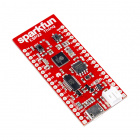
Qwiic VR IMU (BNO080) Hookup Guide

$
0
0

Qwiic VR IMU (BNO080) Hookup Guide a learn.sparkfun.com tutorial

Available online at: http://sfe.io/t764

Introduction

Bosch’s BNO080 is a combination triple axis accelerometer/gyro/magnetometer packaged with an ARM Cortex M0+ running powerful algorithms. The BNO080 Inertial Measurement Unit (IMU) produces accurate rotation vector headings, excellently suited for VR and other heading applications with a static rotation error of 2 degrees or less. It’s what we’ve been waiting for: all the sensor data is combined and drift corrected into meaningful, accurate IMU information. It’s perfect for any project that needs to sense orientation or motion. We’ve taken this IMU and stuck it on a Qwiic enabled breakout board, in order to make interfacing with the tiny, QFN package a bit easier to connect.

SparkFun VR IMU Breakout - BNO080 (Qwiic)

SEN-14686
$34.95

In this hookup guide, we’ll connect our sensor up to our microcontroller of choice and separately read the rotation vectors (which is what we will mainly want), acceleration vectors, gyro values, and magnetometer vectors. We’ll check out how to implement the step counter on the BNO080 in order to use it as a pedometer. We’ll also read Q values and various other metadata from the sensor. Knowing what activity you’re performing is important so we’ll learn how to classify what activity the IMU is performing (i.e. Sitting still, moving, biking, walking, running, etc…) and how confident the IMU is that each activity is being performed. The examples will also show how to calibrate our hardware to give us the most accurate readings possible. Printing out raw packets will also be examined for debugging purposes. Finally, we’ll examine how to configure the sensor on different I2C ports and addresses. A bonus example is provided in Processing to show us how to use quaternion data to orient a cube.

Required Materials

To get started, you’ll need a microcontroller to, well, control everything.

SparkFun RedBoard - Programmed with Arduino

DEV-13975
$19.95
27
SparkFun ESP32 Thing

DEV-13907
$19.95
52
Raspberry Pi 3

DEV-13825
$39.95
90
Particle Photon (Headers)

WRL-13774
$19.00
28

Now to get into the Qwiic ecosystem, the key will be one of the following Qwiic shields to match your preference of microcontroller:

SparkFun Qwiic Shield for Arduino

DEV-14352
$5.95
SparkFun Qwiic HAT for Raspberry Pi

DEV-14459
$4.95
1
SparkFun Qwiic Shield for Photon

DEV-14477
$4.95

You will also need a Qwiic cable to connect the shield to your accelerometer, choose a length that suits your needs.

Qwiic Cable - 500mm

PRT-14429
$1.95
Qwiic Cable - 200mm

PRT-14428
$1.50
Qwiic Cable - 100mm

PRT-14427
$1.50
Qwiic Cable - 50mm

PRT-14426
$0.95

Suggested Reading

If you aren’t familiar with our new Qwiic system, we recommend reading here for an overview. We would also recommend taking a look at the following tutorials if you aren’t familiar with them. We also delve into Processing in this tutorial, if you aren’t familiar, check out the below tutorial on Processing.

Serial Communication

Asynchronous serial communication concepts: packets, signal levels, baud rates, UARTs and more!

Gyroscope

Gyroscopes measure the speed of rotation around an axis and are an essential part in determines ones orientation in space.

Accelerometer Basics

A quick introduction to accelerometers, how they work, and why they're used.

Connecting Arduino to Processing

Send serial data from Arduino to Processing and back - even at the same time!

I2C

An introduction to I2C, one of the main embedded communications protocols in use today.

Qwiic Shield for Arduino & Photon Hookup Guide

Get started with our Qwiic ecosystem with the Qwiic shield for Arduino or Photon.

Hardware Overview

Let’s look over a few characteristics of the BNO080 sensor so we know a bit more about how it behaves.

CharacteristicRange
Operating Voltage1.65V - 3.6V
Linear Acceleration Accuracy&plusmn.35m/s
Gyroscope Accuracy&plusmn.35m/s
I2C Address0x4A (S0 Grounded) or 0x4B (S0 pulled high)

Pins

There are multiple rows of pins on the BNO080, the first row, used for the default I2C interface (configurable up to 400 kHz) is explained in the table below.

Pin LabelPin FunctionInput/OutputNotes
PS0Protocol SelectionInputConfiguration of the communication interface (Default: 0, I2C)
PS1Protocol SelectionInputConfiguration of the communication interface (Default: 0, I2C)
GNDGroundInput0V/common voltage.
3V3Power SupplyInputShould be between 1.65 - 3.6V
SDAI2C Data SignalBi-directionalBi-directional data line. Voltage should not exceed power supply (e.g. 3.3V).
SCLI2C Clock SignalInputMaster-controlled clock signal. Voltage should not exceed power supply (e.g. 3.3V).
RSTReset SignalInputReset signal, active low, pull low to reset IC
INTInterruptOutputInterrupt, active low, pulls low when the BNO080 is ready for communication.

Also broken out on the board is a Serial Peripheral Interface (SPI) which can run data up to 3MHz. The pins for this interface are outlined below. On any pin, the voltage should not exceed that supplied on the 3V3 pin.

Pin LabelPin FunctionInput/OutputNotes
GNDGroundInput0V/Common Voltage
3V3PowerInputShould be between 1.65 - 3.6V
SCKMaster ClockInputClock signal to synchronize master and slave.
SOMISOOutputMaster in , slave out. Device sends data to the master on this line.
SIMOSI/ADDRInputMaster out, slave in. Device receives data from the microcontroller on this line. Tie to 3.3V to change I2C address from 0x4A to 0x4B
CSChip SelectInputChip select, active low, used as chip select/slave select on SPI
WAKWakeInputActive low, Used to wake the processor from a sleep mode.
RSTReset SignalInputReset signal, active low, pull low to reset IC

You can also use the UART interface at up to 3 Mbps or a simplified UART called UART-RVC (Used for robotic vacuum cleaners) which can run at a data rate of 115200 kbps. The UART interface is in the middle of the board, with the black and green pins labeled on the back of the board as shown below. Also note the BOOT pin next to the Qwiic connector, which is necessary for configuration of the communication mode. If the BOOT pin is low upon reset or power up, the chip will go into bootloader mode to allow for programming of new firmware.

Boot Pin

Optional Features

Pull-Up Resistor Jumper

The Qwiic VR IMU has onboard I2C pull up resistors, which can be removed by removing the solder from the jumper highlighted below. Only remove this solder if you are using your own pull-ups on the I2C lines.

I2C Pullup

Protocol Selection Jumpers

You can use the PS0 and PS1 jumpers to change the communication protocol that the BNO080 is using. The jumpers are left open (0) by default, and the following configurations will allow for their corresponding communications protocols.

PS0PS1Interface
00I2C
10UART-RVC
01UART
11SPI

The jumpers themselves are located on the back of the board, shown below

Protocol Selection

I2C Jumper

You can also change the address of the BNO080 from 0x4A (default) to 0x4B by connecting the I2C ADR jumper. The jumper itself is shown in the below image.

Address Jumper

Axis Reference

Also, be sure to check out the labeling on the front of the board that indicates the orientation of the positive X, Y, and Z axes so you know which way your data is pointing.

Axis Reference Photo

Hardware Assembly

If you haven’t yet assembled your Qwiic Shield, now would be the time to head on over to that tutorial. With the shield assembled, Sparkfun’s new Qwiic environment means that connecting the sensor could not be easier. Just plug one end of the Qwiic cable into the BNO080 breakout, the other into the Qwiic Shield of your choice and you’ll be ready to upload a sketch and figure out how you’re moving that board. It seems like it’s too easy too use, but that’s why we made it that way!

Connected IMU

Library Overview

Note: This example assumes you are using the latest version of the Arduino IDE on your desktop. If this is your first time using Arduino, please review our tutorial on installing the Arduino IDE. If you have not previously installed an Arduino library, please check out our installation guide.

Before we get into programming our IMU, let’s download and check out the available functions in our library. SparkFun has written a library to control the Qwiic VR IMU. You can obtain these libraries through the Arduino Library Manager. Search for SparkFun BNO080 Cortex Based IMU and you should be able to install the latest version. If you prefer manually downloading the libraries from the GitHub repository, you can grab them here:

Download the SparkFun BNO080 Cortex Based IMU Library (ZIP)

Let’s get started by looking at the functions that set up the IMU.

Setup and Settings

  • boolean begin(uint8_t deviceAddress = BNO080_DEFAULT_ADDRESS, TwoWire &wirePort = Wire);— By default use the default I2C address, and use Wire port, otherwise, pass in a custom I2C address and wire port.

  • void enableDebugging(Stream &debugPort = Serial);— Turn on debug printing. If user doesn’t specify method of printing then Serial will be used.

  • void enableRotationVector(uint16_t timeBetweenReports);— Enables the rotation vector to give a report every timeBetweenReports ms.
  • void enableGameRotationVector(uint16_t timeBetweenReports);— Enables the game rotation vector to give a report every timeBetweenReports ms.
  • void enableAccelerometer(uint16_t timeBetweenReports);— Enables the accelerometer with timeBetweenReports in ms.
  • void enableGyro(uint16_t timeBetweenReports);— Enables the gyroscope with timeBetweenReports in ms.
  • **void enableMagnetometer(uint16_t timeBetweenReports);— Enables the magnetometer with timeBetweenReports in ms.
  • void enableStepCounter(uint16_t timeBetweenReports);— Enables the step counter with timeBetweenReports in ms.
  • void enableStabilityClassifier(uint16_t timeBetweenReports);— Enables the stability classifier with timeBetweenReports in ms.
  • void enableActivityClassifier(uint16_t timeBetweenReports, uint32_t activitiesToEnable,
         uint8_t (&activityConfidences)[9]);— Enables the activity classifier with a timeBetweenReports (in ms), the activitiesToEnable (0x1F to enable all activities) and the activityConfidences[9] array to store the IMU’s confidence that the activity is occurring.

  • void softReset();— Try to reset the IMU via software

  • uint8_t resetReason();— Query the IMU for the reason it last reset

  • float qToFloat(int16_t fixedPointValue, uint8_t qPoint);— Given a Q value, converts fixed point floating to regular floating point number

  • void setFeatureCommand(uint8_t reportID, uint16_t timeBetweenReports();— Used to enable different sensors and functions (features) of the IMU with to report with timeBetweenReports ms between reports.

  • void setFeatureCommand(uint8_t reportID, uint16_t timeBetweenReports, uint32_t specificConfig);— Used to enable different sensors and functions (features) of the IMU with to report with timeBetweenReports ms between reports.
  • void sendCommand(uint8_t command);— Sends a command to the sensor.
  • void sendCalibrateCommand(uint8_t thingToCalibrate);— Sends calibrations commands to the sensor of choice. Possible arguments are listed below.
    • CALIBRATE_ACCEL
    • CALIBRATE_GYRO
    • CALIBRATE_MAG
    • CALIBRATE_PLANAR_ACCEL
    • CALIBRATE_ACCEL_GYRO_MAG— Calibrates all sensors.
    • CALIBRATE_STOP— Stops all calibration.

Communication and Data Handling

  • boolean waitForI2C();— Delay based polling for I2C traffic
  • boolean receivePacket(void);— Receives an I2C packet from the IMU.
  • boolean getData(uint16_t bytesRemaining);— Given a number of bytes, send the requests in I2C_BUFFER_LENGTH chunks
  • boolean sendPacket(uint8_t channelNumber, uint8_t dataLength);— Sends a packet of length dataLength to channelNumber.
  • void printPacket(void);— Prints the current shtp header and data packets

  • bool dataAvailable(void);— Checks if new data is available from the IMU.

  • void parseInputReport(void);— Takes the data from the IMu and places it into the proper variable so they can be properly read.

Getting Values

  • float getQuatI();— Retrieves the i-axis quaternion from the IMU.
  • float getQuatJ();— Retrieves the j-axis quaternion from the IMU.
  • float getQuatK();— Retrieves the k-axis quaternion from the IMU.
  • float getQuatReal();— Retrieves the real component of the quaternion from the IMU.
  • float getQuatRadianAccuracy();— Retrieves the accuracy of the quaternion from the IMU in radians.
  • uint8_t getQuatAccuracy();— Retrieves the accuracy of the quaternion from the IMU.

  • float getAccelX();— Retrieves the x-axis acceleration.

  • float getAccelY();— Retrieves the y-axis acceleration.
  • float getAccelZ();— Retrieves the z-axis acceleration.
  • uint8_t getAccelAccuracy();— Retrieves the accuracy of the accelerometer readings.

  • float getGyroX();— Retrieves the x-axis gyroscope reading.

  • float getGyroY();— Retrieves the y-axis gyroscope reading.
  • float getGyroZ();— Retrieves the z-axis gyroscope reading.
  • uint8_t getGyroAccuracy();— Retrieves the accuracy of the gyroscope reading.

  • float getMagX();— Retrieves the x-axis magnetometer reading.

  • float getMagY();— Retrieves the y-axis magnetometer reading.
  • float getMagZ();— Retrieves the z-axis magnetometer reading.
  • uint8_t getMagAccuracy();— Retrieves the accuracy of the magnetometer reading.

Sensor Calibration

Check the calibration procedure in order to calibrate the IMU with the functions listed below.

  • void calibrateAccelerometer();— Begins the calibration function for the IMU’s accelerometer.
  • void calibrateGyro();— Begins the calibration function for the IMU’s gyroscope.
  • void calibrateMagnetometer();— Begins the calibration function for the IMU’s magnetometer.
  • void calibratePlanarAccelerometer();— Begins the planar calibration function for the IMU’s accelerometer.
  • void calibrateAll();— Begins all calibration functions.
  • void endCalibration();— Ends the active calibration functions.
  • void saveCalibration();— Saves data from current calibration.

Special Functions

  • uint16_t getStepCount();— Gets the number of steps from the BNO080’s onboard pedometer.
  • uint8_t getStabilityClassifier();— Retrieves the stability classification, a number between 0 and 6.
    • 0— Unknown classification
    • 1— On table
    • 2— Stationary
    • 3— Stable
    • 4— Motion
    • 5— Reserved
  • uint8_t getActivityClassifier();— Retrieves the Activity classification, a number between 0 and 8, based on a comparison of the confidence levels in each activity.
    • 0— Unknown
    • 1— In Vehicle
    • 2— On Bicycle
    • 3— On Foot
    • 4— Still
    • 5— Tilting
    • 6— Walking
    • 7— Running
    • 8— On stairs

Metadata Handling Functions

  • int16_t getQ1(uint16_t recordID);— Given a record ID, read the Q1 value from the metaData record in the Flash Record System (FRS). Q1 is used for all sensor data calculations.
  • int16_t getQ2(uint16_t recordID);— Given a record ID, read the Q2 value from the metaData record in the FRS. Q2 is used in sensor bias.
  • int16_t getQ3(uint16_t recordID);— Given a record ID, read the Q3 value from the metaData record in the FRS. Q3 is used in sensor change sensitivity.
  • float getResolution(uint16_t recordID);— Given a record ID, reads the resolution value from the sensors metadata
  • float getRange(uint16_t recordID);— Given a record ID, read the range value from the metaData record in the FRS for a given sensor
  • **uint32_t readFRSword(uint16_t recordID, uint8_t wordNumber);— Given a record ID and a word number, find the word data. Used in getQ1(), getResolution(), etc..
  • void frsReadRequest(uint16_t recordID, uint16_t readOffset, uint16_t blockSize);— Ask the sensor for data from the Flash Record System.
  • bool readFRSdata(uint16_t recordID, uint8_t startLocation, uint8_t wordsToRead);— Reads data from the Flash Record System.

Global Variables

  • uint8_t shtpHeader[4];— In Hillcrest’s Sensor Hubtransfer Protocol, each packet has a header of 4 bytes
  • uint8_t shtpData[MAX_PACKET_SIZE];— Creates an array for SHTP data to be stored.
  • uint8_t sequenceNumber[6] = {0, 0, 0, 0, 0, 0};— There are 6 com channels. Each channel has its own sequence number.
  • uint8_t commandSequenceNumber = 0;— Commands have a sequence number as well. These are inside command packet, the header uses its own sequence number for each channel.
  • uint32_t metaData[MAX_METADATA_SIZE];— There is more than 10 words in a metadata record but we’ll stop at Q point 3

Arduino Example Code

Now that we have our library installed, we can get started playing around with our examples to learn more about how the IMU behaves. From there we’ll be able to build our own custom code to integrate the sensor into a project.

Example 1 - Rotation Vector

This first example gets us started taking a reading of our complex valued rotation vector, or quaternion, which tells us how we are oriented. To get started, open up Example1-RotationVector under File>Examples>SparkFun BNO080 Cortex Based IMU>Example1-RotationVector. To access all of the functions in the BNO080 library we’ll have to include the library and create an IMU object, this is accomplished in the following lines of code.

language:c
#include "SparkFun_BNO080_Arduino_Library.h"
BNO080 myIMU;

In our setup(), we’ll have to initialize the sensor and enable the parts of the sensor (gyro, accelerometer, magnetometer) that we want to obtain readings from. We’ll also tell the IMU how often we want a reading from our sensor of choice by passing this value into our enable function in ms. The code outlining this sensor setup is shown below. Pay attention to this as we’ll be performing a similar setup in many of the remaining examples.

language:c
Serial.begin(9600); //Don't forget to enable Serial to talk to your microcontroller
Serial.println();
Serial.println("BNO080 Read Example");

Wire.begin(); //Begin the I2C bus
Wire.setClock(400000); //Increase I2C data rate to 400kHz

myIMU.begin()
myIMU.enableRotationVector(50); //Send data update every 50ms

Now that our sensor is setup, we can look at our void loop() to see how we obtain and print data. When the loop executes, it begins by checking to see if the sensor has new data with myIMU.dataAvailable(), which returns true when new data is available. We then proceed to get the i, j, k, and real quaternion values along with the accuracy in radians of our measurement using the following lines of code.

language:c
float quatI = myIMU.getQuatI();
float quatJ = myIMU.getQuatJ();
float quatK = myIMU.getQuatK();
float quatReal = myIMU.getQuatReal();
float quatRadianAccuracy = myIMU.getQuatRadianAccuracy();

Printing the rotation vector is then as easy as using a few Serial.print(quatI, 2) statements. Uploading the code and opening the Serial Monitor to a baud rate of 9600 should yield an output similar to the below image.

Quaternion Serial Output

Example 2 - Accelerometer

Examples 2 deals with pulling the accelerometer values from our sensor to figure out how it is moving. To get started, open up Example2-Accelerometer under File>Examples>SparkFun BNO080 Cortex Based IMU>Example2-Accelerometer. At first glance, you’ll notice that the way we set up our IMU is nearly identical to the first example. The one difference being in our setup(), where we call myIMU.enableAccelerometer(50); instead of myIMU.enableRotationVector(50); which has the accelerometer report a value every 50 ms. We once again obtain and output our data in our void loop() by waiting for data using myIMU.dataAvailable(). Once data is available we use the following lines of code to get our x, y, and z acceleration values.

language:c
float x = myIMU.getAccelX();
float y = myIMU.getAccelY();
float z = myIMU.getAccelZ();

We can then print these values to get our acceleration vector, uploading the code, and opening the Serial Monitor to a baud rate of 9600 should yield an output similar to the below image.

Accelerometer Serial Output

Example 3 - Gyro

In example 3, we’ll pull values from the IMU’s gyroscope to get a vector for our angular velocity. To get started, open up Example3-Gyro under File>Examples>SparkFun BNO080 Cortex Based IMU>Example3-Gyro. The differences between this example and example 1 are very similar to the differences between examples 1 & 2. We initialize the sensor the exact same way as example 1 only calling myIMU.enableGyro(50); instead of myIMU.enableRotationVector(50); to have the gyro report it’s value every 50 ms. We once again obtain and output our data in our void loop() by waiting for data using myIMU.dataAvailable(). Once data is available, we use the following lines of code to get our x, y, and z gyroscope values.

language:c
float x = myIMU.getGyroX();
float y = myIMU.getGyroY();
float z = myIMU.getGyroZ();

We can then print these values to get our gyroscope angular velocity vector, uploading the code, and opening the Serial Monitor to a baud rate of 9600 should yield an output similar to the below image.

Gyroscope Serial Monitor

Also, check out the values in a graph by opening the Serial Plotter to the same baud rate to see the readings from each gyroscope channel plotted against each other. Rotate the IMU and see how the values respond, I got the following output just letting the IMU swing on its cable.

Gyroscope Serial Plotter

Example 4 - Magnetometer

The following example will get us reading a vector for the magnetic field. To get started, open up Example4-Magnetometer under File>Examples>SparkFun BNO080 Cortex Based IMU>Example4-Magnetometer. The differences between this example and example 1 are very similar to the differences between examples 1 & 2, are you starting to see a pattern here? We initialize the sensor the exact same way as example 1 only calling myIMU.enableMagnetometer(50); instead of myIMU.enableRotationVector(50); to have the magnetometer report it’s value every 50 ms. We once again obtain and output our data in our void loop() by waiting for data using myIMU.dataAvailable(). Once data is available we use the following lines of code to get our x, y, and z magnetometer values. We also obtain the uncertainty in the magnetometer.

language:c
float x = myIMU.getMagX();
float y = myIMU.getMagY();
float z = myIMU.getMagZ();
byte accuracy = myIMU.getMagAccuracy();

We can then print these values to get our magnetometer vector, uploading the code, and opening the Serial Monitor to a baud rate of 9600 should yield an output similar to the below image.

Magnetometer Serial Output

Example 5 - Step Counter

The BNO080 has some really neat built in features due to its built in Cortex. One of these is a built in step counter. To get started with this pedometer, open up Example5-StepCounter under File>Examples>SparkFun BNO080 Cortex Based IMU>Example5-StepCounter. The differences between this example and example 1 are very similar to the differences in the previous examples. We initialize our step counter function with a lower sample rate than our previous functions as we don’t expect steps to happen at as high of a rate. Due to this, we call myIMU.enableStepCounter(500) to allow for a half a second in between reports. We once again obtain and output our data in our void loop() by waiting for data using myIMU.dataAvailable(). Once data is available, we pull the amount of steps from the IMU using unsigned int steps = myIMU.getStepCount() to initialize and populate an unsigned int with the step count. We then print this value to our serial monitor. Uploading the code and opening the Serial Monitor to a baud rate of 9600 should yield an output similar to the below image.

Step Counter

Example 6 - Metadata

This example shows us how to retrieve the static metadata from the different sensors in the IMU. To get started, open up Example6-Metadata under File>Examples>SparkFun BNO080 Cortex Based IMU>Example6-Metadata. Notice how this example has an empty void loop()? Everything just happens once in our setup() loop. To get the metadata for a sensor, we simply pass its corresponding FRS_RECORD_ID into getRange(), getResolution(), getQ1(), getQ2(), and getQ3() to retrieve the metadata for a sensor. The different FRS_RECORD_ID variables are shown below.

language:c
#define FRS_RECORDID_ACCELEROMETER 0xE302
#define FRS_RECORDID_GYROSCOPE_CALIBRATED 0xE306
#define FRS_RECORDID_MAGNETIC_FIELD_CALIBRATED 0xE309
#define FRS_RECORDID_ROTATION_VECTOR 0xE30B

These are then used like so to print the different parts of each sensors metadata. For a little bit more on metadata, check out page 29 of the Reference Manual. Uploading the code and opening the Serial Monitor to a baud rate of 9600 should yield an output similar to the below image.

Metadata

Example 7 - Stability Classifier

This example sketch allows us to use the built in stability classifier to figure out how stable the IMU is. To get started, open up Example7-StabilityClassifier under File>Examples>SparkFun BNO080 Cortex Based IMU>Example7-StabilityClassifier. This example is very similar to our first few examples in that we must call myIMU.enableStabilityClassifier(50); in our setup() function to have the stability classifier report its data every 50 ms. However, we also need to call myIMU.calibrateGyro() in our setup() function to enable all of our stability classification outputs. We then check if data is available using myIMU.dataAvailable(). If it is, we pull the stability classification (a number from 0-5 using myIMU.getStabilityClassifier() ) and output the text corresponding to the classification. The code that does this in the void loop() is shown below. Also, take note of which number corresponds to which activity.

language:c
if (myIMU.dataAvailable() == true)
  {
    byte classification = myIMU.getStabilityClassifier();

    if(classification == 0) Serial.print(F("Unknown classification"));
    else if(classification == 1) Serial.print(F("On table"));
    else if(classification == 2) Serial.print(F("Stationary"));
    else if(classification == 3) Serial.print(F("Stable"));
    else if(classification == 4) Serial.print(F("Motion"));
    else if(classification == 5) Serial.print(F("[Reserved]"));

    Serial.println();
  }

Uploading the code and opening the Serial Monitor to a baud rate of 9600 should yield an output similar to the below image.

Stability Classifier

Example 8 - Activity Classifier

The activity classifier is somewhat similar to the stability classifier in that it uses the on-board cortex to determine what activity the IMU is doing. To get started, open up Example8-ActivityClassifier under File>Examples>SparkFun BNO080 Cortex Based IMU>Example8-ActivityClassifier. To set up the activity classifier, we need to tell the IMU which activities to look for. We do this using a 32-bit word. There are only 8 possible activities at the moment, so we set our word enableActivities = 0x1F to enable everything. The activity classifier also gives a confidence level in each activity. To store these confidences, we create a variable byte activityConfidences[9] above our setup() function. Then, we can set up the activity classifier in our setup() function by calling myIMU.enableActivityClassifier(50, enableActivities, activityConfidences);. Using this function enables the activity classifier with 50 ms between reports, activities specified by enableActivities, and their confidences are stored in activityConfidences. We then check if data is available using myIMU.dataAvailable(). If it is, we pull the activity classification (a number from 0-9 using myIMU.getActivityClassifier()) and output the text corresponding to the classification. The code that does this is shown below. Take note of which number corresponds to which activity.

language:c
void loop()
{
  //Look for reports from the IMU
  if (myIMU.dataAvailable() == true)
  {
    //getActivityClassifier will modify our activityConfidences array
    //It will return the most likely activity as well.
    byte mostLikelyActivity = myIMU.getActivityClassifier(); 

    Serial.print("Most likely activity: ");
    printActivityName(mostLikelyActivity);
    Serial.println();

    Serial.println("Confidence levels:");
    for(int x = 0 ; x < 9 ; x++)
    {
      printActivityName(x);
      Serial.print(F(") "));
      Serial.print(activityConfidences[x]);
      Serial.print(F("%"));
      Serial.println();
    }

    Serial.println();
  }
}

//Given a number between 0 and 8, print the name of the activity
//See page 73 of reference manual for activity list
void printActivityName(byte activityNumber)
{
  if(activityNumber == 0) Serial.print("Unknown");
  else if(activityNumber == 1) Serial.print("In vehicle");
  else if(activityNumber == 2) Serial.print("On bicycle");
  else if(activityNumber == 3) Serial.print("On foot");
  else if(activityNumber == 4) Serial.print("Still");
  else if(activityNumber == 5) Serial.print("Tilting");
  else if(activityNumber == 6) Serial.print("Walking");
  else if(activityNumber == 7) Serial.print("Running");
  else if(activityNumber == 8) Serial.print("On stairs");
}

The output of this code should look something like the below image.

Activity Classifier

Example 9 - Calibrate

When moving between different magnetic environments (different rooms, indoors, outdoors, etc…), it might be necessary to recalibrate your IMU to obtain the best readings. In order to do this, we’ll run a calibration function,. To get started, open up Example9-Calibrate under File>Examples>SparkFun BNO080 Cortex Based IMU>Example9-Calibrate. In our setup function, we call the function myIMU.calibrateAll() to begin calibration of our sensor. We also need to make sure the we enable our game rotation vector and magnetometer as these are necessary for calculating the calibration of the magnetometer. Go ahead and upload the code to the IMU and open the serial monitor to 9600 baud. Take a look at your output and look for the calibration status. This should probably say Unreliable. Make sure you’re in a clean magnetic environment and go through the calibration steps listed in the calibration procedure. Once your sensor is calibrated, your accuracy should change from Unreliable to Medium or High. After calibration, send an s to your microcontroller over the serial monitor to run the following code and save the calibration.

language:c
if(incoming == 's')
{
  myIMU.saveCalibration(); //Saves the current dynamic calibration data (DCD) to memory
  myIMU.endCalibration(); //Turns off all calibration
  Serial.println("Calibration ended");
  }
}

Your Serial Monitor should look something like the following image when the sensor is being calibrated. Remember, when your confidence levels are satisfactory, send an s to save the calibration.

Calibration

Example 10 - Print Packet

Sometimes it’s easier to look at the raw data coming from the sensor for debugging purposes. This example shows you how to do just that. To get started, open up Example10-PrintPacket under File>Examples>SparkFun BNO080 Cortex Based IMU>Example10-PrintPacket. In our setup, we set up the sensors that we would like to use (in this case, we’ll set up the magnetometer and accelerometer with 1000 ms sample rates). Since we’re most likely debugging in this mode, we’ll also call myIMU.enableDebugging(Serial). Our void loop() then simply listens for and prints packets using the below code.

language:c
void loop()
{
  //Look for reports from the IMU
  if (myIMU.receivePacket() == true)
  {
    myIMU.printPacket();
  }
}

Your Serial Monitor should look something like the following image with this example code uploaded. Make sure to change the baud rate to 115200 as opposed to 9600 like the previous examples.

Print Packet Example

Example 11 - Advanced Configuration

The final example simply shows us how to configure the sensor on different addresses and I2C buses. To get started, open up Example11-AdvancedConfig under File>Examples>SparkFun BNO080 Cortex Based IMU>Example11-AdvancedConfig. This is simply a matter of setting up the sensor differently. Instead of calling myIMU.begin() with no arguments, we call it as myIMU.begin(0x4A, Wire1). If we’ve pulled the SI pin high, the address will be 0x4B. We can also set up the sensor on a different I2C bus if by passing in Wire2 in place of Wire1.

Bonus Example - Serial Cube Visualizer

Note: Processing is a software that enables visual representation of data, among other things. If you've never dealt with Processing before, we recommend you also check out the Arduino to Processing tutorial. Follow the below button to go ahead and download and install Processing.

Download Processing IDE

This extra example isn’t included in the library as it requires Processing. To grab it, go ahead and download or clone the BNO080 Github Repo.

Download BNO080 Github Repo (ZIP)

Processing listens for serial data, so we’ll need to get our Arduino producing serial data that makes sense to Processing. The required Arduino sketch is located in Qwiic_IMU_BNO080 > Software > Serial_Cube_Rotate > Serial_Cube_Rotate.ino. This sketch simply prints a list of our quaternions separated by a comma over serial for Processing to listen to.

Once this sketch is uploaded, we need to tell Processing how to turn this data into a visualization. The Processing sketch to do this is located one folder above the Arduino sketch, in Qwiic_IMU_BNO080 > Software > Serial_Cube_Rotate.pde. Open the Serial_Cube_Rotate file in Processing. Before running the sketch, we’ll need to download ToxicLibs, a library used for computational design. To do this, go to Sketch > Import Library… > Add Library…. Then search for and download ToxicLibs. Attempting to run the Processing sketch will show us available serial ports in the debug window from this line of code.

language:c
myPort = new Serial(this, Serial.list()[0], 115200);

Identify which serial port your Arduino is on. For instance, my RedBoard is on COM6, which corresponds to [1] in the image below, so I will need to change 0 to 1 in the following line to ensure Processing is listening to the correct serial port.

Serial Ports

Once we’ve done this, we should be able to run the Processing sketch and it will give us a nice visualization of how our IMU is oriented in 3D space as a cube. Try rotating the IMU to see how it responds. You should get a neat little output like the one in the below GIF.

Processing Cube Example

Resources and Going Further

Thanks for reading! We’re excited to see what you build with the Qwiic VR IMU. If you’re left needing more BNO080-related documentation, check out some of these resources:

Need some inspiration for your next project? Check out some of these related tutorials:

Dungeons and Dragons Dice Gauntlet

A playful, geeky tutorial for a leather bracer that uses a LilyPad Arduino, LilyPad accelerometer, and seven segment display to roll virtual 4, 6, 8, 10, 12, 20, and 100 side dice for gaming.

Das Blinken Top Hat

A top hat decked out with LED strips makes for a heck of a wedding gift.

Blynk Board Washer/Dryer Alarm

How to configure the Blynk Board and app to notify you when your washer or dryer is done shaking.

9DoF Razor IMU M0 Hookup Guide

How to use and re-program the 9DoF Razor IMU M0, a combination of ATSAMD21 ARM Cortex-M0 microprocessor and MPU-9250 9DoF-in-a-chip.

Raspberry Pi Zero Helmet Impact Force Monitor

How much impact can the human body handle? This tutorial will teach you how to build your very own impact force monitor using a helmet, Raspberry Pi Zero, and accelerometer!

learn.sparkfun.com | CC BY-SA 3.0 | SparkFun Electronics | Niwot, Colorado
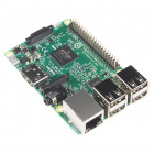

WiFi Controlled Robot

$
0
0

WiFi Controlled Robot a learn.sparkfun.com tutorial

Available online at: http://sfe.io/t755

Introduction

This tutorial will show you how to build an Internet controlled robot with a live video stream to a custom site hosted by the ESP32 Thing. With a little hacking you can customize the robot to create your own pan/tilt camera or even a Nerf Sentry Gun that can be remotely controlled!

Camera Robot

This project is based around the Shadow Chassis, which is controlled by the ESP32 Thing and the Serial Controlled Motor Driver.

Required Materials

To build this project, you will need the following:

Not included in the wishlist is a WiFi camera that you will need to source. When picking a camera, keep a few things in mind:

  • Power supply voltage: Ideally the camera can be powered from USB, so that the ESP32 and camera can share the same 5V rail.
  • 2.4GHz WiFi connection: So that the ESP32 and camera can share the same network.
  • Framerate: Higher is better. The best I was able to find was 30 frames per second, but due to real world conditions, expect it to be around half of what is outlined in the technical details.
  • Accessible with an HTTP link: For this you’ll have to do some googling, but if you type in the manufacturer and model number followed by “URL” (e.g. “Wansview 1080p URL”) you should find a link that will show you what to put in the address bar of your browser to view the video stream. We’ll discuss how to use that URL in the camera testing section.

Suggested Reading

Before starting this project, there may be a few subjects you’ll want to be familiar with before starting this project.

How to Solder: Through-Hole Soldering

This tutorial covers everything you need to know about through-hole soldering.

Serial Communication

Asynchronous serial communication concepts: packets, signal levels, baud rates, UARTs and more!

Installing an Arduino Library

How do I install a custom Arduino library? It's easy!

Assembly Guide for RedBot with Shadow Chassis

Assembly Guide for the RedBot Kit. This tutorial includes extra parts to follow to go along with the RedBot Inventor's Kit tutorial.

ESP32 Thing Hookup Guide

An introduction to the ESP32 Thing's hardware features, and a primer on using the WiFi/Bluetooth system-on-chip in Arduino.

Serial Controlled Motor Driver Hookup Guide

Hookup guide for the Serial Controlled Motor Driver

ESP32 Thing Motion Shield Hookup Guide

Getting started with the ESP32 Thing Motion Shield to detect movements using the on-board LSM9DS1 IMU and adding a GPS receiver. Data can be easily logged by adding an microSD card to the slot.

Hardware Hookup

The first step is assembling the hardware. To get started, assemble the shadow chassis. You can find detailed instructions in this guide:


Assembly Guide for Redbot with Shadow Chassis

All that’s needed for this tutorial is assembling the chassis and mounting the motors.

Assembling the Electronics

To assemble to electronics, use the schematic below:

ESP32 Camera Robot Schematic

Click the image for a closer look.

It’s good practice to do a few sanity checks as you put this together.

Start with the battery connections and build up to the 5V DC/DC converter. Once the DC/DC converter is in place, measure the output voltage and make sure you’re seeing close to 5V.

Schematic Overview

Power is supplied from the 7.4V (2-Cell) Lipo battery. Running Lipo batteries down below a safe voltage (3V per cell, or 6V in this case) can cause damage to the battery which can cause it to fail or shorten the life of the battery. To make sure we don’t run our battery flat, we’ll use a panel voltmeter to monitor the battery’s voltage. At 6V, the battery is considered flat, and needs to be recharged. According to the DC/DC converter’s datasheet, the regulator has an input voltage range of 7-28VDC, but in my testing the regulator will work as low as 6.5V. Below this input voltage, the regulator will output 0VDC, so you will need to change the battery when the output voltage drops below 6.5V.

The raw battery voltage is also directly fed into the Serial Controlled Motor Driver (SCMD), which can handle up to 11V to drive the motors. The SCMD can run off 5V, but with a lower voltage the motors will draw less current, which will extend battery life, but have less torque and move slower.

DC to DC Converter Pinout

To power the ESP32 Thing, Motion Shield, and Camera, we’ll need to regulate the battery’s voltage down to 5V. To do that we’ll use a 5V DC/DC converter which has 3-pins: VIN, GND, VOUT (see pinout above). VIN is the battery voltage which should be between 6 and 8.4V, VOUT is 5.0V, and GND is GND. The DC/DC converter is recommended over a standard LM7805, because it is more efficient than a linear regulator and extends the battery life. With a linear regulator the wasted power is converted to heat, and with the ESP32 and camera drawing around 500mA of current, a linear regulator (such as the LM7805) would be hot to the touch.

For signal wires, most of the data signals are connected when you plug the Motion Shield into the ESP32. The only signal wire that will need to be soldered is the TX pin of the ESP32 to the SCMD. When everything is soldered together, it should look like this:

Assembled Electronics

Click the image for a closer look.

Wire Color Code:

  • YELLOW: Battery Voltage
  • BLACK: Ground
  • BLUE: 5.0V
  • GREEN: Signal

Motor Connections:

  • Left Motor+ (RED): SCMD A2
  • Left Motor- (BLACK): SCMD A1
  • Right Motor+ (RED): SCMD B2
  • Right Motor- (BLACK): SCMD B1

Motor Wiring Test

Note: This example assumes you are using the latest version of the Arduino IDE on your desktop. If this is your first time using Arduino, please review our tutorial on installing the Arduino IDE. If you have not previously installed an Arduino library, please check out our installation guide.

Now that we have the robot put together, let’s add some code! But before we get ahead of ourselves, let’s test to make sure everything is working. The first thing we want to do is make sure the motors are working correctly. What we’re looking for is that when we send a command, the wheels move in the correct direction. Specifically:

  • Forward: Both wheels spin forward
  • Reverse: Both wheels spin in reverse
  • Left: Left wheel spins in reverse, right wheel spins forward
  • Right: Left wheel spins forward, right wheel spins in reverse

If you haven’t uploaded code to an ESP32 before, check out the hookup guide to learn how to program the ESP32 Thing in Arduino.

ESP32 Hookup Guide - Installing the Arduino Core

Once you have the board definitions installed, upload the following sketch to your ESP32:

language:cpp
/*
 * Alex Wende SparkFun Electronics
 * ESP32 Motor Wiring Test
 * 
 * In this example we'll send motor commands to the Serial Controlled Motor Driver (SCMD)
 * to see how the motors respond based on the commands we send.
 * 
 * Commands used:
 * "D\r\n" - Sends a disable command to stop the motors
 * "E\r\n" - Sends a enable command to turn the motors on
 * "M0F50\r\n" - Tells the motor driver to spin motor 0 forwards at 50% power
 * "M1R100\r\n" - Tells the motor driver to spin motor 1 in reverse at 100% power
 */

byte counter = 0;

void setup()
{
  Serial.begin(9600); // Initialize serial port to the SCMD's default baud rate
  delay(500);         // Wait a bit to make sure the SCMD is ready
}

void loop()
{
  if(counter == 0)
  {
    Serial.println("Sending Forward Command:");
    delay(50);
    Serial.print("D\r\n");
    delay(50);
    Serial.print("M0F50\r\n");
    delay(50);
    Serial.print("M1F50\r\n");
    delay(50);
    Serial.print("E\r\n");
  }
  else if(counter == 1)
  {
    Serial.println("Sending Reverse Command:");
    delay(50);
    Serial.print("D\r\n");
    delay(50);
    Serial.print("M0R50\r\n");
    delay(50);
    Serial.print("M1R50\r\n");
    delay(50);
    Serial.print("E\r\n");
  }
  else if(counter == 2)
  {
    Serial.println("Sending Left Command:");
    delay(50);
    Serial.print("D\r\n");
    delay(50);
    Serial.print("M0R50\r\n");
    delay(50);
    Serial.print("M1F50\r\n");
    delay(50);
    Serial.print("E\r\n");
  }
  else
  {
    Serial.println("Sending Right Command:");
    delay(50);
    Serial.print("D\r\n");
    delay(50);
    Serial.print("M0F50\r\n");
    delay(50);
    Serial.print("M1R50\r\n");
    delay(50);
    Serial.print("E\r\n");
  }

  counter++;
  if(counter > 3)
  {
    counter = 0;
  }
  delay(5000);
}

Once the code has uploaded, open up your serial terminal. Make sure the baud rate is set to 9600, and you should see messages like this:

Motor Command Test Serial Window

Pay attention the messages stating which command was sent, and verify that what was sent reflects what happened. If nothing moves, make sure you have power connected correctly and your motors are connected to the SCMD, and that you set the baud rate to 9600 in your Arduino sketch (not just in the terminal window). If one (or both) motors spins in the opposite direction than it should, you can fix it by swapping the motor connections to the SCMD.

Another option is to correct it in software. If the forward command was sent but motor0 spins in reverse, replace M0F50\r\n with M0R50\r\n. Another possibility is if the forward/reverse commands work, but the left/right commands are backwards, swap the M0 and M1 in the left and right command blocks. If you need to make changes in the software, remember which ones need to be changed when we add code to the final example.

Controlling the Motors From a Web Page

Now that we know the motors are working correctly, we’ll next try to control them from a web page hosted by the ESP32 Thing. To do this, we’ll load the Arduino code on to the ESP32. Copy and paste the following code into Arduino and upload it to the board. All of the libraries come with Arduino and the ESP32 bootloader core except for ESP32WebServer.h which you can download from the link below:

ESP32 Web Server Arduino Library

Note: You'll need to replace the * for the SSID and password with the name of your WiFi network and it's password. If you modified the motor commands from the previous example to work with your motor wiring, you'll need to apply those changes in the `handleMotors()` function as well.

language:cpp
/* 
 *  Alex Wende SparkFun Electronics
 *  ESP32 Web Controlled Motor Test
 *  
 *  To use this code, download the ESP32WebServer library from:
 *  https://github.com/Pedroalbuquerque/ESP32WebServer
 *  
 *  In this Example we'll use the arrow keys from our keyboard to send commands to the Serial 
 *  Controlled Motor Driver. When the ESP32 connects to the WiFi network, the ESP32 sends the
 *  IP address over the Serial to the terminal window at 9600 baud. Copy and paste the IP 
 *  address into your brower's window to go to the ESp32's web page. From there, use the arrow keys
 *  to control the motors.
 *  
 *  UP Arrow - Drive Forward
 *  DOWN Arrow - Drive in Reverse
 *  LEFT Arrow - Turn Left
 *  RIGHT Arrow - Turn Righ
 *  
 *  If the motors aren't spinning in the correct direction, you'll need to to change the motor
 *  number and/or motor direction in the handleMotors() function.
 */

#include <WiFiClient.h>
#include <ESP32WebServer.h>
#include <WiFi.h>
#include <SPI.h>
#include <SD.h>

const char* ssid = "*************";
const char* password = "*********";

ESP32WebServer server(80);  //Default port number

void handleRoot()
{  
  /* we load the index.html from microSD */
  File myFile = SD.open("/index.html");
  if (myFile) 
  {  
    /* respond the content of file to client by calling streamFile()*/
    size_t sent = server.streamFile(myFile, "text/html");
    /* close the file */
    myFile.close();
  } 
  else
  {
    Serial.println("error opening index.html");
  }
}

//XML page to listen for motor commands
void handleMotors() 
{ 
  String motorState = "OFF";
  String t_state = server.arg("motorState"); //Refer  xhttp.open("GET", "setMotors?motorState="+motorData, true);

  Serial.print("D\r\n"); //Disable motors
  delay(50);

  if(t_state.startsWith("U"))  //Drive Forward (UP Arrow)
  {
    Serial.print("M0F70\r\n");
    delay(50);
    Serial.print("M1F70\r\n");
    delay(50);
    Serial.print("E\r\n");
  }
  else if(t_state.startsWith("D")) //Reverse (DOWN Arrow)
  {
    Serial.print("M0R70\r\n");
    delay(50);
    Serial.print("M1R70\r\n");
    delay(50);
    Serial.print("E\r\n");
  }
  else if(t_state.startsWith("R")) //Turn Right (Right Arrow)
  {
    Serial.print("M0F50\r\n");
    delay(50);
    Serial.print("M1R50\r\n");
    delay(50);
    Serial.print("E\r\n");
  }
  else if(t_state.startsWith("L")) //Turn Left (LEFT Arrow)
  {
    Serial.print("M0R50\r\n");
    delay(50);
    Serial.print("M1F50\r\n");
    delay(50);
    Serial.print("E\r\n");
  }

   server.send(200, "text/plain", motorState); //Send web page
}

// cannot handle request so return 404
void handleNotFound()
{
  server.send(404, "text/plain", "File Not Found\n\n");
}

void setup(){
  Serial.begin(9600); //SCMD + debug messages
  WiFi.begin(ssid, password); //WiFi network to connect to

  Serial.println();

  // Wait for connection
  while (WiFi.status() != WL_CONNECTED) {
    delay(500);
    Serial.print(".");
  }
  Serial.println("");
  Serial.print("Connected to ");
  Serial.println(ssid);
  Serial.print("IP address: ");
  Serial.println(WiFi.localIP());

  /* register the callbacks to process client request */
  /* root request we will read the memory card to get 
  the content of index.html and respond that content to client */
  server.on("/", handleRoot);
  server.on("/setMotors", handleMotors);
  server.onNotFound(handleNotFound);
  server.begin(); //Start the web server

  Serial.println("HTTP server started");
  Serial.print("Initializing SD card...");

  /* initialize microSD */
  if (!SD.begin(33)) {
    Serial.println("initialization failed!");
    return;
  }
  Serial.println("initialization done.");
}

void loop(){
  server.handleClient();
}

The Arduino code doesn’t include any of the HTML code that your browser needs to display the web page. For that we’ll need to load the HTML file on to a microSD card. You could also directly load the HTML code into the handleRoot() function, but by keeping the HTML code on a microSD card, we can eject the SD card and change the code, faster than it would take to recompile the ESP32 code and re-upload it to the board.

To put the code on the SD card, we’ll plug the card into our computer and create a file called “index.html”, which will have the following code saved to that file:

language:HTML
<!DOCTYPE html>
<html>
    <head>
        <meta charset="UTF-8">
        <title> Web Server Motor Control Test </title>
        <script type="text/javascript">
            var sendCommand = 1;

            //Key Pressed
            document.addEventListener("keydown", function (evt) {
                if (evt.keyCode == "38"&& sendCommand) {   // up arrow
                    sendData("U") 
                    sendCommand = 0;
                }
                else if (evt.keyCode == "40"&& sendCommand) {  // down arrow
                    sendData("D") 
                    sendCommand = 0;
                }
                else if (evt.keyCode == "37"&& sendCommand) {  // left arrow
                    sendData("L") 
                    sendCommand = 0;
                }
                else if (evt.keyCode == "39"&& sendCommand) {  // right arrow
                    sendData("R")
                    sendCommand = 0;
                }
            });

            //Key Released
            document.addEventListener("keyup", function (evt) {
                if(evt.keyCode == "37" || evt.keyCode == "38" || evt.keyCode == "39" || evt.keyCode == "40") {
                    sendData("STOP");
                    sendCommand = 1;
                }
            });

            function sendData(motorData) {  //Send data for ESP32 to resond to
                var xhttp = new XMLHttpRequest();
                xhttp.onreadystatechange = function() {
                    if (this.readyState == 4 && this.status == 200) {
                    }
                };
                xhttp.open("GET", "setMotors?motorState="+motorData, true);
                xhttp.send();
            }
        </script>
    </head>
    <body>
        <h2>SparkFun ESP32 Thing Motor Control Test</h2>
        <ul> 
            <li>Use the arrow keys send commands to the motors.</li>
            <li>When a arrow key is pressed, this page sends a XML request for the ESP32 to respond to.</li>
            <li>The ESP32 responds by sending a motor command to the Serial Controlled Motor Driver. </li>
            <li>By sending a XML request, we're able to control the motors without having to reload the page!</li>
        </ul>
   </body>
</html>

Once you have that file saved as a .html, you can eject the SD card and plug it into the Motion Shield and open the your terminal window. You may need to press the reset button on your ESP32 Thing to view the debug messages. If all goes well you should see the following in your terminal window:

Motor Control Web Server Example Serial Window

If you only see “…”, it means that it’s not connecting to your WiFi network. Make sure the SSID and password is correct. If the SD card failed to initialize, it could be that you forgot to plug in the SD card, or it could be that the chip select pin is incorrect. For the Motion Shield it should be GPIO pin 33.

Once the ESP32 has connected to the network, and the SD card is initialized, you can try to access the web page. Make sure your computer is on the same network as the ESP32, and enter the IP address of the ESP32 into the address bar of your browser. It should display the following page:

Motor Test Web Page

Click the image for a closer look.

From this page, when you press the arrow keys you should see the motors respond. As you press the arrow keys, check to make sure the motors respond correctly to the arrow keys. If not, you’ll need to modify the code in the handleMotors() function to move forward when the up arrow key is pressed, reverse when the down arrow key is pressed, and so on.

Testing the WiFi Camera

As mentioned at the end of the Introduction, you’ll need to source your own WiFi camera, which makes it difficult to show you how to get image or video data from your camera into a web page, because each manufacturer will do things differently. To get started, you’ll need to do some googling. Search for the manufacturer’s name and the camera’s model number followed by “URL” (e.g. “Wansview 1080p URL”), and you should find a link that will show you what to put in the address bar of your browser to view the video stream.

For the camera I’m using, there are two links to see what the camera sees:

  • video stream: “rtsp://[IP ADDRESS]:[PORT]/live/ch0?user=[USERNAME]&pwd=[PASSWORD]”
  • snapshot (takes a photo of what the camera can see): “http://[IP ADDRESS]:[PORT]/mjpeg/snap.cgi?user=[USERNAME]&pwd=[PASSWORD]”.

The first URL provides the video stream using the Real Time Streaming Protocol (RTSP). If you have a video player (such as VLC) installed on your computer, you can open a network stream with the RTSP link and fill in the specific information of your camera (IP address, port number, user name and password) to view the video stream.

VLC RTSP Stream

Click the image for a closer look.

Unfortunately, an RTSP stream isn’t native to HTML5. There are Javascript libraries which will convert the protocol to use in a <video> tag, but there’s another option available which allow us to create a video if we don’t need to use the camera’s microphone and speaker. The second URL uses the Hypertext Transfer Protocol (HTTP) to take a single picture from the camera. With a few lines of Javascript code, we’ll be able refresh the image being loaded onto the page to look like a video. You can test the link by opening your browser and entering the HTTP URL into the address bar and fill in the specific information of your camera (IP address, port number, user name, and password) to take a photo. If all goes well, you should see the photo in the browser.

Camera Snapshot

Click the image for a closer look.

WiFi Camera Robot Software

Now that the wiring works, the motors can be controlled from a web page, and we know the URL for our camera works, we can finally put it all together. All we need to do is eject the microSD card from our Motion Shield and change the HTML code on our computer.

Note: Make sure to fill in the correct URL for your camera in the image tag as well as in the reloadImg() Javascript function.

language:HTML
<!DOCTYPE html>
<html>
    <head>
        <meta charset="UTF-8">

        <script type="text/javascript">
            var sendCommand = 1;
            var count = 0;

            document.addEventListener("keydown", function (evt) {
                count = count + 1;
                if(count > 10) {
                    count = 2;
                }
                if(count > 2) {
                    if (evt.keyCode == "38"&& sendCommand) {
                        sendData("D1") // up arrow
                        sendCommand = 0;
                    }
                    else if (evt.keyCode == "40"&& sendCommand) {
                        sendData("U1") // down arrow
                        sendCommand = 0;
                    }
                    else if (evt.keyCode == "37"&& sendCommand) {
                        sendData("L1") // left arrow
                        sendCommand = 0;
                    }
                    else if (evt.keyCode == "39"&& sendCommand) {
                        sendData("R1")// right arrow
                        sendCommand = 0;
                    }
                }

            });

            document.addEventListener("keyup", function (evt) {
                if(count > 2) {
                    if(evt.keyCode == "37" || evt.keyCode == "38" || evt.keyCode == "39" || evt.keyCode == "40") {
                        sendData("STOP");
                        sendCommand = 1;
                    }
                    count = 0;
                }
                else {
                    if (evt.keyCode == "38"&& sendCommand) {
                        sendData("D3") // up arrow
                    }
                    else if (evt.keyCode == "40"&& sendCommand) {
                        sendData("U3") // down arrow
                    }
                    else if (evt.keyCode == "37"&& sendCommand) {
                        sendData("L3") // left arrow
                    }
                    else if (evt.keyCode == "39"&& sendCommand) {
                        sendData("R3")// right arrow
                    }
                    count = 0;
                    sendCommand = 1;
                }

            });

            function sendData(motorData) {
                var xhttp = new XMLHttpRequest();
                xhttp.onreadystatechange = function() {
                    if (this.readyState == 4 && this.status == 200) {
                    }
                };
                xhttp.open("GET", "setMotors?motorState="+motorData, true);
                xhttp.send();
            }

            var refreshRate = 5; //ms

            function reload()
            {
                setTimeout('reloadImg("refresh")',refreshRate)
            };

            function reloadImg(id)
            {
                var obj = document.getElementById(id);
                var date = new Date();
                obj.src = "http://[IP ADDRESS]:[PORT]/mjpeg/snap.cgi?chn=1?user=[USERNAME]&pwd=[PASSWORD]&t=" + Math.floor(date.getTime()/refreshRate);
            }
        </script>
    </head>
    <body>
        <h2>SparkFun ESP32 Thing + WiFi Camera Remote Control</h2>
        <img src="http://[IP ADDRESS]:[PORT]/mjpeg/snap.cgi?chn=1?user=[USERNAME]&pwd=[PASSWORD]" name="refresh" id="refresh" onload='reload(this)' onerror='reload(this)'>
        <br/>
        <ul> 
            <li>Use the arrow keys send commands to the motors.</li>
            <li>When a arrow key is pressed, this page sends a XML request for the ESP32 to respond to.</li>
            <li>The ESP32 responds by sending a motor command to the Serial Controlled Motor Driver. </li>
            <li>By sending a XML request, we're able to control the motors without having to reload the page!</li>
        </ul>
   </body>
</html>

This HTML file has a few changes from the Controlling the Motors From a Web Page example. The most obvious change is the <img> tag which calls the reloadImg() function. In the reloadImg() Javascript function, we refresh the image every 5ms. In the URL of the function, we added on “&t=[Time in Milliseconds]”; without it the browser will assume it’s the same image and to save time reload that image with the same image without talking to the camera. Adding on the time parameter will make the browser think it’s a new URL and retrieve it instead of reloading the same image that it stored in the cached memory.

Resources and Going Further

This tutorial is based on a blog post from a few weeks back. Check it out!

Because this project is Open Source, you can expand on this project and make it your own. By adding port forwarding to your router, you could make the robot accessible from anywhere in the world if you have an Internet connection. Or maybe you want to replace the motors with servos to create your own pan/tilt camera, or even a nerf gun for a remote controlled sentry!

Or if you’re looking for another project to put your ESP8266/ESP32 to work, check out some of our other great tutorials!

LED Cloud-Connected Cloud

Make an RGB colored cloud light! You can also control it from your phone, or hook up to the weather!

ESP8266 Powered Propane Poofer

Learn how Nick Poole built a WiFi controlled fire-cannon using the ESP8266 Thing Dev Board!

IoT Industrial Scale

What does a baby elephant weigh? How much impact force does a jump have? Answer these questions and more by building your very own IoT industrial scale using the SparkFun OpenScale.

Using Artnet DMX and the ESP32 to Drive Pixels

In this tutorial, we'll find out how to use Resolume Arena, a popular video jockey software, to control custom-made ArtNet DMX fixtures.

learn.sparkfun.com | CC BY-SA 3.0 | SparkFun Electronics | Niwot, Colorado
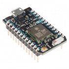
Qwiic Magnetometer Hookup Guide

$
0
0

Qwiic Magnetometer Hookup Guide a learn.sparkfun.com tutorial

Available online at: http://sfe.io/t759

Introduction

The MLX90393 is a tri-axial magnetic sensor capable of sensing very small fields (like the Earth’s magnetic field) while behaving as one would want and expect during saturation in larger fields (like a nearby magnet). It turns out the favorite HMC5883L and other such sensors that are intended for compass applications have a low dynamic range but also strange and undefined behavior in large fields. Ted Yapo did an incredibly extensive characterization of the sensor over on Hackaday. He published his controlled experiments testing a few sensors and found the MLX90393 to be superior.

The MLX90393 can be used as a compass sensor but also works well as a non-contact controller (joystick), flow meter (with magnetic impeller), or a linear actuator position sensor. The breakout board is also a part of SparkFun’s Qwiic system, so you won’t have to do any soldering to figure out what the magnetic fields look like.

SparkFun Triple Axis Magnetometer Breakout - MLX90393 (Qwiic)

SEN-14571
$14.95

In this hookup guide, we’ll get going by getting some basic readings from the sensor, then look at how to configure the sensor on different I2C addresses.

Required Materials

To get started, you’ll need a microcontroller to control everything in your project.

SparkFun RedBoard - Programmed with Arduino

DEV-13975
$19.95
27
SparkFun ESP32 Thing

DEV-13907
$19.95
52
Raspberry Pi 3

DEV-13825
$39.95
90
Particle Photon (Headers)

WRL-13774
$19.00
28

Now, to get your microcontroller into the Qwiic ecosystem, the key will be one of the following Qwiic shields to match your preference of microcontroller:

SparkFun Qwiic Shield for Arduino

DEV-14352
$5.95
SparkFun Qwiic HAT for Raspberry Pi

DEV-14459
$4.95
1
SparkFun Qwiic Shield for Photon

DEV-14477
$4.95

You will also need a Qwiic cable to connect the shield to your magnetometer, choose a length that suits your needs.

Qwiic Cable - 500mm

PRT-14429
$1.95
Qwiic Cable - 200mm

PRT-14428
$1.50
Qwiic Cable - 100mm

PRT-14427
$1.50
Qwiic Cable - 50mm

PRT-14426
$0.95

Or, here’s the wishlist to follow along exactly with this guide:

Suggested Reading

If you aren’t familiar with our new Qwiic system, we recommend checking out our overview:

WHAT IS QWIIC?

We would also recommend taking a look at the hookup guide for the Qwiic Shield if you haven’t already. Brushing up on your skills in I2C is also recommended, as all Qwiic sensors are I2C.

I2C

An introduction to I2C, one of the main embedded communications protocols in use today.

Serial Terminal Basics

This tutorial will show you how to communicate with your serial devices using a variety of terminal emulator applications.

Qwiic Shield for Arduino & Photon Hookup Guide

Get started with our Qwiic ecosystem with the Qwiic shield for Arduino or Photon.

Hardware Overview

Let’s look over a few characteristics of the MLX90393 so we know a bit more about how it behaves.

CharacteristicRange
Operating Voltage2.2V - 3.6V
Operating Temperature-20&degC - 85&degC
Resolution0.161 &microT
Current Consumption100 &microA (Typ.)
I2C Address0xC0

Pins

The characteristics of the available pins on the magnetometer are outlined in the table below.

Pin LabelPin FunctionInput/OutputNotes
3.3VPower SupplyInputShould be between 2.2V - 3.6V
GNDGroundInput0V/common voltage.
SDAI2C Data SignalBi-directionalBi-directional data line. Voltage should not exceed power supply (e.g. 3.3V).
SCL/SCLKI2C Clock SignalInputMaster-controlled clock signal. Voltage should not exceed power supply (e.g. 3.3V).
I2C Data SignalBi-directionalBi-directional data line. Voltage should not exceed power supply (e.g. 3.3V).
CSChip SelectInputChip Select pin, digital input. Tied high for I2C operation, cut trace jumper and tie low for SPI.
INTInterruptOutputInterrupt pin, active high, digital output. Also configurable as a data ready pin
TRIGResetInput/OutputTrigger pin, active high, digital output. Also configurable as interrupt pin.

Optional Features

The Qwiic MLX90393 has onboard I2C pull up resistors, which can be removed by removing the solder from the jumper highlighted below. Only remove this solder if you are using your own pullups on the I2C lines.

I2C Pullup Jumper

The I2C of the Qwiic Magnetometer can be changed using the A0 and A1 jumpers on the back of the board. Simply cut the traces connecting each pad to ground (0) and solder the other side to connect it to 3.3V (1).

Address Jumper

To operate the Qwiic Magnetometer in SPI mode, cut the chip select trace jumper (labeled below) and ensure that the CS pin is then connected to ground.

Chip Select Jumper

Hardware Assembly

If you haven’t yet assembled your Qwiic Shield, now would be the time to head on over to that tutorial.

Qwiic Shield for Arduino Photon Hookup Guide

With the shield assembled, SparkFun’s new Qwiic environment means that connecting the sensor could not be easier. Just plug one end of the Qwiic cable into the Magnetometer breakout, the other into the Qwiic Shield of your choice and you’ll be ready to upload a sketch and figure out what the magnetic fields look like. It seems like it’s too easy to use, but that’s why we made it that way!

Connected Magnetometer

Example Code

Before we get into programming our Magnetometer, we’ll need to download and install the magnetometer library. Ted Yapo has written a library to control the Qwiic Magnetometer. You can obtain the .zip for this library using the below button. Never installed a library before? That’s ok! Checkout our tutorial on installing Arduino Libraries.

Download the MLX90393 Library

Note: This example assumes you are using the latest version of the Arduino IDE on your desktop. If this is your first time using Arduino, please review our tutorial on installing the Arduino IDE. If you have not previously installed an Arduino library, please check out our installation guide.

Since this isn’t a SparkFun library, the example sketches are not included, so you’ll have to download those from the Github page by clicking the below button. The example sketches are located in software

Download the MLX90393 Github Repo

Go ahead and unzip these examples to a location of your choosing and open Example 1 - Basic Readings.

Example 1 - Basic Readings

Once we have our first example opened up, let’s look at how things are structured as we set up our sensor. First we create our sensor, and then an array of floats to contain our data.

language:c
MLX90393 mlx;
MLX90393::txyz data; //Create a structure, called data, of four floats (t, x, y, and z)

Then in our setup loop, we must initialize our sensor, notice the delay afterwards, this gives the sensor time to initialize before we start attempting to talk to it.

language:c
mlx.begin(); //Assumes I2C jumpers are GND. No DRDY pin used.
delay(1000); //Allow the sensor to initialize.

Once the sensor is initialized, our void loop() will read the data from our sensor into data, the array of floats we created earlier, and print it over serial to our serial monitor. Opening up your serial monitor to a baud rate of 9600 should display output similar to that shown below. The numbers are in units of µT. For scale, the magnetic field of the Earth ranges from 25 - 65 µT.

Basic Sensor Readings

Example 2 - Configure Sensor

Go ahead and open Example 2 from the location you saved it in. The only differences between this example and the previous one are in the setup() function. Notice how we now call the begin() function with 3 arguments, which are the value of the A0 jumper, the value of the A1 jumper, and the pin that we’ve connected to INT. The below code assumes that the A0 jumper has been cut from ground and soldered to 3.3V and that A3 is connected to the INT pin (sometimes referred to in the datasheet as the DRDY or data ready pin).

language:c
byte status = mlx.begin(1, 0, A3);

If we must change the address of our magnetometer due to overlapping addresses, ensure that the values we pass into begin() match up with the values of our address jumpers. The MLX90393 also has a ton of different ways to change the sensor behavior. You can set the gain, resolution of the x, y and z channels, oversampling rates, and even offsets of your x, y, and z channels. In this example however, we set the gain to 1 and the resolution of our x, y, and z channels to their finest setting, 0.

language:c
mlx.setGainSel(1);
mlx.setResolution(0, 0, 0);

A table showing the different possible resolutions of the sensor for the X and Y axes is shown below. These can be selected using the setGainSel(uint8_t gain) and setResolution(uint8_t x, uint8_t y, uint8_t z) functions. All resolutions are in units of µT/LSB.

XY Axis:

GainRes = 0Res = 1Res = 2Res = 3
00.8051.6103.2206.440
10.6441.2882.5765.152
20.4830.9661.9323.864
30.4030.8051.6103.220
40.3220.6441.2882.576
50.2680.5371.0732.147
60.2150.4290.8591.717
70.1610.3220.6441.288

Shown below is the table containing the possible combinations for resolutions on the Z axis. Once again, units are in µT/LSB

Z Axis:

GainRes = 0Res = 1Res = 2Res = 3
01.4682.9365.87211.744
11.1742.3494.6989.395
20.8811.7623.5237.046
30.7341.4682.9365.872
40.5871.1742.3494.698
50.4890.9791.9573.915
60.3910.7831.5663.132
70.2940.5871.1742.349

Since we are simply connecting our magnetometer on a different address, our output should be similar to the one in the first example.

Resources and Going Further

For more information, check out the resources below:

Need some inspiration for your next project? Check out some of these related tutorials:

AS726X NIR/VIS Spectral Sensor Hookup Guide

It's now easier than ever to measure and characterize how different materials absorb and reflect different wavelengths of light. The AS726X spectral sensors allow you to detect wavelengths in the visible range (VIS) and near infrared range (NIR)!

Qwiic HAT for Raspberry Pi Hookup Guide

Get started interfacing your Qwiic enabled boards with your Raspberry Pi. This Qwiic connects the I2C bus (GND, 3.3V, SDA, and SCL) on your Raspberry Pi to an array of Qwiic connectors.

Qwiic Micro OLED Hookup Guide

Get started displaying things with the Qwiic Micro OLED.
New!

Qwiic Accelerometer (MMA8452Q) Hookup Guide

Freescale’s MMA8452Q is a smart, low-power, three-axis, capacitive micro-machined accelerometer with 12-bits of resolution. It’s perfect for any project that needs to sense orientation or motion. We’ve taken that accelerometer and stuck it on a Qwiic-Enabled breakout board to make interfacing with the tiny, QFN package a bit easier.

learn.sparkfun.com | CC BY-SA 3.0 | SparkFun Electronics | Niwot, Colorado

Qwiic GRID-Eye Infrared Array (AMG88xx) Hookup Guide

$
0
0

Qwiic GRID-Eye Infrared Array (AMG88xx) Hookup Guide a learn.sparkfun.com tutorial

Available online at: http://sfe.io/t746

Introduction

The Grid-EYE from Panasonic is an 8x8 thermopile array. This means you have a square array of 64 pixels each capable of independent temperature detection. It’s like having thermal camera (or Predator’s vision), just in really low resolution. It’s part of SparkFun’s Qwiic system, so it is easier to connect to get your low-resolution infrared image.

SparkFun Grid-EYE Infrared Array Breakout - AMG8833 (Qwiic)

SEN-14607
$39.95

In this hookup guide, we’ll connect our sensor up to our microcontroller of choice and read the array simply as 0’s and 1’s in an Arduino Serial Monitor. We’ll also read the interrupt array to find out which pixels are detecting a value higher than a certain threshold. We’ll go over how to check the temperature of the chip itself using the built in thermistor. Once we figure out how to interface with the GRID-Eye in our Arduino IDE, we’ll move over to Processing to get some neat visuals from our pixel array, and actually get a nice looking thermal camera.

Required Materials

To get started, you’ll need a microcontroller to control everything in your project.

SparkFun RedBoard - Programmed with Arduino

DEV-13975
$19.95
27
SparkFun ESP32 Thing

DEV-13907
$19.95
52
Raspberry Pi 3

DEV-13825
$39.95
90
Particle Photon (Headers)

WRL-13774
$19.00
28

Now to get your microcontroller into the Qwiic ecosystem, the key will be one of the following Qwiic shields to match your preference of microcontroller:

SparkFun Qwiic Shield for Arduino

DEV-14352
$5.95
SparkFun Qwiic HAT for Raspberry Pi

DEV-14459
$4.95
1
SparkFun Qwiic Shield for Photon

DEV-14477
$4.95

You will also need a Qwiic cable to connect the shield to your GRID-Eye, choose a length that suits your needs.

Qwiic Cable - 500mm

PRT-14429
$1.95
Qwiic Cable - 200mm

PRT-14428
$1.50
Qwiic Cable - 100mm

PRT-14427
$1.50
Qwiic Cable - 50mm

PRT-14426
$0.95

Suggested Reading

If you aren’t familiar with our new Qwiic system, we recommend reading here for an overview. We would also recommend taking a look at the hookup guide for the Qwiic Shield if you haven’t already. Brushing up on your skills in I2C is also recommended, as all Qwiic sensors are I2C. Since we’ll also be using Processing in one of these demos, we’d recommend looking up the tutorial on hooking your Arduino up to Processing.

Connecting Arduino to Processing

Send serial data from Arduino to Processing and back - even at the same time!

I2C

An introduction to I2C, one of the main embedded communications protocols in use today.

Qwiic Shield for Arduino & Photon Hookup Guide

Get started with our Qwiic ecosystem with the Qwiic shield for Arduino or Photon.

Hardware Overview

Let’s look over a few characteristics of the Qwiic Grid-EYE so we know a bit more about how it behaves.

CharacteristicRange
Operating Voltage(Startup)1.6V - 3.6V
Operating Voltage(Timekeeping)1.5V - 3.6V
Operating Temperature-40&degC - 85&degC
Time Accuracy&plusmn2.0 ppm
Temperature Accuracy&plusmn2.5&degC
Current Consumption4.5 mA
I2C Address0x69 (open jumper, default) or 0x68 (closed jumper)

Pins

The characteristics of the available pins on the Grid-EYE are outlined in the table below.

Pin LabelPin FunctionInput/OutputNotes
3.3VPower SupplyInputShould be between 1.95 - 3.6V
SDAI2C Data SignalBi-directionalBi-directional data line. Voltage should not exceed power supply (e.g. 3.3V).
SCLI2C Clock SignalInputMaster-controlled clock signal. Voltage should not exceed power supply (e.g. 3.3V).
INTInterruptOutputInterrupt pin, digital output.
GNDGroundInput0V/common voltage.

Optional Features

Pull-Up Resistors

The Qwiic GRID-Eye has onboard I2C pull-up resistors, which can be removed by removing the solder from the jumper highlighted below. Only remove this solder if you are using your own pull-ups on the I2C lines.

I2C Pullup Jumper

I2C Address

There is an additional jumper on the back of the board that allows the I2C to be changed from the default 0x69 to 0x68 if you have multiple GRID-Eye cameras on the same I2C bus. Normally open, the jumper sets the I2C address to 0x69. Closing the jumper with solder will give an I2C address of 0x68. However, if you have more than 2 GRID-Eye’s, you’ll need the Qwiic Mux to have them all on the same I2C bus. The jumper is highlighted below.

Address Jumper

Hardware Assembly

If you haven’t yet assembled your Qwiic Shield, now would be the time to head on over to that tutorial. With the shield assembled, Sparkfun’s new Qwiic environment means that connecting the sensor could not be easier. Just plug one end of the Qwiic cable into the GRID-Eye breakout, the other into the Qwiic Shield of your choice and you’ll be ready to upload a sketch and figure out how far away you are from that thing over there. It seems like it’s too easy too use, but that’s why we made it that way!

Connected GridEYE to Arduino

Arduino Example Code

Note: This example assumes you are using the latest version of the Arduino IDE on your desktop. If this is your first time using Arduino, please review our tutorial on installing the Arduino IDE. If you have not previously installed an Arduino library, please check out our installation guide.

SparkFun has written a library to control the Qwiic GRID-Eye. You can obtain these libraries through the Arduino Library Manager. Search for SparkFun GridEYE AMG88 Library and you should be able to install the latest version. If you prefer downloading the libraries manually you can grab them from the GitHub repository:

Download the SparkFun GRID-Eye Library (ZIP)

Example 1 - Serial Visualizer

Once you’ve installed the Grid-EYE library, restart Arduino. Then go to File>Examples>SparkFun GridEYE AMG88 Library>Example1-SerialVisualizer to open the example sketch.

Once you’ve set your Board and Serial Port, upload the sketch to your Arduino. Then open the serial monitor. You’ll begin to see an 8x8 array of numbers between 0 and 3. The Arduino is mapping the values in between the temperatures between HOT and COLD to values between 0 and 3, these values are then represented by a . for 0, o for 1, 0for 2, and O for 3. Try moving in front of the camera and see if any values change. Play around with the values of HOT and COLD as well to see different ranges of temperatures mapped from 0 to 3. Notice how we use the function grideye.getPixelTemperature(i) to get the temperature of pixel i, where i is between 0 and 64. With these temperatures mapped to a grid, the output should look something like the below image.

Serial Pixel Visualizer

Example 2 - Using Interrupts

To pull up the next example, go to File>Examples>SparkFun GridEYE AMG88 Library>Example2-UsingInterrupts to open the example sketch.

Once you’ve loaded this example up to your microcontroller, go ahead and check out the void setup() loop. We set up how the Interrupts are triggered with the following code.

language:c
grideye.setInterruptModeAbsolute();
grideye.setUpperInterruptValue(UPPER_LIMIT);
grideye.setLowerInterruptValue(LOWER_LIMIT);
grideye.setInterruptHysteresis(HYSTERESIS);

Where UPPER_LIMIT, LOWER_LIMIT, and HYSTERESIS are declared above. Opening the serial monitor will display a table of which interrupts have been fired, if any. Play around with the values of UPPER_LIMIT, LOWER_LIMIT, and HYSTERESIS and observe their effect on the firing of interrupts. The interrupt table should look similar to the below image, obviously with different interrupts firing depending on what the Grid-EYE is looking at.

Interrupt Table

Example 3 - Device Temperature

To pull up the next example, go to File>Examples>SparkFun GridEYE AMG88 Library>Example3-DeviceTemperature to open the example sketch. This example is relatively simple, and merely checks the devices temperature. To get device temperature, there are 3 functions we can use, getDeviceTemperature(), which returns our temperature in Celsius, getDeviceTemperatureFahrenheit(), which returns our temperature in Fahrenheit getDeviceTemperatureRaw() returns the raw binary content of the thermistor register. Opening the serial monitor should yield an image similar to the one below.

Devide Temperature

Example 4 - Processing Heat Cam

Note: Processing is a software that enables visual representation of data, among other things. If you've never dealt with Processing before, we recommend you also check out the Arduino to Processing tutorial. Follow the below button to go ahead and download and install Processing.

Download Processing IDE

This next example involves the Processing IDE. Processing listens for serial data, so we’ll need to get our Arduino producing serial data that makes sense to Processing. To pull up the next example, go to File>Examples>SparkFun GridEYE AMG88 Library>Example4-ProcessingHeatCam to open the example sketch. This sketch simply prints a comma separated list of our temperatures over serial for Processing to listen to.

Once this sketch is uploaded, we need to tell Processing how to turn this data into a visualization. The Processing sketch to do this is located in the same folder as Example 4. So go to Documents>Arduino>SparkFun_GridEYE_AMG88_Library>examples>Example4-ProcessingHeatCam>HeatCam and open the HeatCam file in Processing. Attempting to run the sketch will show us available serial ports in the debug window.

COM Port Selection

Identify which serial port your Arduino is on, for instance, my RedBoard is on COM6, which corresponds to [1] in the above image, so I will need to change 0 to 1 in the following line to ensure Processing is listening in the right location.

language:c
myPort = new Serial(this, Serial.list()[0], 115200);

Once I’ve done this, we should be able to run the Processing sketch and it will give us a nice visualization of the pixels on our Grid-EYE. Move your face or hand in front of the sensor and see what it looks like on the screen. The output should look similar to the below image, which is output from the Grid-EYE being pointed at a glass of ice water and a lava lamp.

Processing Heat Cam

Example 5 - Hot Pixel

To pull up the next example, go to File>Examples>SparkFun GridEYE AMG88 Library>Example5-HotPixel to open the example sketch. This example runs through each pixel and finds the hottest one, then outputs the location and temperature of that pixel. It does this by comparing the current hotPixelValue temperature to the temperature of the current pixel. If the current pixel is hotter, its value is stored in hotPixelValue. The output of this sketch should look something like the below image.

Hot Pixel

Resources and Going Further

Thanks for reading! Now that you’ve successfully got your Grid-EYE up and running, it’s time to incorporate it into your own project! We’re excited to see what you build with the Grid-EYE. If you’re left needing more Grid-EYE-related documentation, check out some of these resources:

Need some inspiration for your next project? Check out some of these related tutorials:

FLIR Lepton Hookup Guide

See the invisible world of infrared radiation using the FLIR Dev Kit and Raspberry Pi.

MLX90614 IR Thermometer Hookup Guide

How to use the MLX90614 or our SparkFun IR Thermometer Evaluation Board to take temperatures remotely, over short distances.

Or maybe mirror heat signatures with addressable WS2812 LEDs:

Heat Signatures Mirrored with Addressable WS2812  LEDs

Example code for the demo can be found in GitHubGist - GridEye LED Array Demo


learn.sparkfun.com | CC BY-SA 3.0 | SparkFun Electronics | Niwot, Colorado
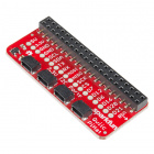
Qwiic Magnetometer (MLX90393) Hookup Guide

$
0
0

Qwiic Magnetometer (MLX90393) Hookup Guide a learn.sparkfun.com tutorial

Available online at: http://sfe.io/t759

Introduction

The MLX90393 is a tri-axial magnetic sensor capable of sensing very small fields (like the Earth’s magnetic field) while behaving as one would want and expect during saturation in larger fields (like a nearby magnet). It turns out the favorite HMC5883L and other such sensors that are intended for compass applications have a low dynamic range but also strange and undefined behavior in large fields. Ted Yapo did an incredibly extensive characterization of the sensor over on Hackaday. He published his controlled experiments testing a few sensors and found the MLX90393 to be superior.

The MLX90393 can be used as a compass sensor but also works well as a non-contact controller (joystick), flow meter (with magnetic impeller), or a linear actuator position sensor. The breakout board is also a part of SparkFun’s Qwiic system, so you won’t have to do any soldering to figure out what the magnetic fields look like.

SparkFun Triple Axis Magnetometer Breakout - MLX90393 (Qwiic)

SEN-14571
$14.95

In this hookup guide, we’ll get going by getting some basic readings from the sensor, then look at how to configure the sensor on different I2C addresses.

Required Materials

To get started, you’ll need a microcontroller to control everything in your project.

SparkFun RedBoard - Programmed with Arduino

DEV-13975
$19.95
27
SparkFun ESP32 Thing

DEV-13907
$19.95
52
Raspberry Pi 3

DEV-13825
$39.95
90
Particle Photon (Headers)

WRL-13774
$19.00
28

Now, to get your microcontroller into the Qwiic ecosystem, the key will be one of the following Qwiic shields to match your preference of microcontroller:

SparkFun Qwiic Shield for Arduino

DEV-14352
$5.95
SparkFun Qwiic HAT for Raspberry Pi

DEV-14459
$4.95
1
SparkFun Qwiic Shield for Photon

DEV-14477
$4.95

You will also need a Qwiic cable to connect the shield to your magnetometer, choose a length that suits your needs.

Qwiic Cable - 500mm

PRT-14429
$1.95
Qwiic Cable - 200mm

PRT-14428
$1.50
Qwiic Cable - 100mm

PRT-14427
$1.50
Qwiic Cable - 50mm

PRT-14426
$0.95

Or, here’s the wishlist to follow along exactly with this guide:

Suggested Reading

If you aren’t familiar with our new Qwiic system, we recommend checking out our overview:

WHAT IS QWIIC?

We would also recommend taking a look at the hookup guide for the Qwiic Shield if you haven’t already. Brushing up on your skills in I2C is also recommended, as all Qwiic sensors are I2C.

I2C

An introduction to I2C, one of the main embedded communications protocols in use today.

Serial Terminal Basics

This tutorial will show you how to communicate with your serial devices using a variety of terminal emulator applications.

Qwiic Shield for Arduino & Photon Hookup Guide

Get started with our Qwiic ecosystem with the Qwiic shield for Arduino or Photon.

Hardware Overview

Let’s look over a few characteristics of the MLX90393 so we know a bit more about how it behaves.

CharacteristicRange
Operating Voltage2.2V - 3.6V
Operating Temperature-20&degC - 85&degC
Resolution0.161 &microT
Current Consumption100 &microA (Typ.)
I2C Address0xC0

Pins

The characteristics of the available pins on the magnetometer are outlined in the table below.

Pin LabelPin FunctionInput/OutputNotes
3.3VPower SupplyInputShould be between 2.2V - 3.6V
GNDGroundInput0V/common voltage.
SDAI2C Data SignalBi-directionalBi-directional data line. Voltage should not exceed power supply (e.g. 3.3V).
SCL/SCLKI2C Clock SignalInputMaster-controlled clock signal. Voltage should not exceed power supply (e.g. 3.3V).
I2C Data SignalBi-directionalBi-directional data line. Voltage should not exceed power supply (e.g. 3.3V).
CSChip SelectInputChip Select pin, digital input. Tied high for I2C operation, cut trace jumper and tie low for SPI.
INTInterruptOutputInterrupt pin, active high, digital output. Also configurable as a data ready pin
TRIGResetInput/OutputTrigger pin, active high, digital output. Also configurable as interrupt pin.

Optional Features

The Qwiic MLX90393 has onboard I2C pull up resistors, which can be removed by removing the solder from the jumper highlighted below. Only remove this solder if you are using your own pullups on the I2C lines.

I2C Pullup Jumper

The I2C of the Qwiic Magnetometer can be changed using the A0 and A1 jumpers on the back of the board. Simply cut the traces connecting each pad to ground (0) and solder the other side to connect it to 3.3V (1).

Address Jumper

To operate the Qwiic Magnetometer in SPI mode, cut the chip select trace jumper (labeled below) and ensure that the CS pin is then connected to ground.

Chip Select Jumper

Hardware Assembly

If you haven’t yet assembled your Qwiic Shield, now would be the time to head on over to that tutorial.

Qwiic Shield for Arduino Photon Hookup Guide

With the shield assembled, SparkFun’s new Qwiic environment means that connecting the sensor could not be easier. Just plug one end of the Qwiic cable into the Magnetometer breakout, the other into the Qwiic Shield of your choice and you’ll be ready to upload a sketch and figure out what the magnetic fields look like. It seems like it’s too easy to use, but that’s why we made it that way!

Connected Magnetometer

Example Code

Before we get into programming our Magnetometer, we’ll need to download and install the magnetometer library. Ted Yapo has written a library to control the Qwiic Magnetometer. You can obtain the .zip for this library using the below button. Never installed a library before? That’s ok! Checkout our tutorial on installing Arduino Libraries.

Download the MLX90393 Library

Note: This example assumes you are using the latest version of the Arduino IDE on your desktop. If this is your first time using Arduino, please review our tutorial on installing the Arduino IDE. If you have not previously installed an Arduino library, please check out our installation guide.

Since this isn’t a SparkFun library, the example sketches are not included, so you’ll have to download those from the Github page by clicking the below button. The example sketches are located in software

Download the MLX90393 Github Repo

Go ahead and unzip these examples to a location of your choosing and open Example 1 - Basic Readings.

Example 1 - Basic Readings

Once we have our first example opened up, let’s look at how things are structured as we set up our sensor. First we create our sensor, and then an array of floats to contain our data.

language:c
MLX90393 mlx;
MLX90393::txyz data; //Create a structure, called data, of four floats (t, x, y, and z)

Then in our setup loop, we must initialize our sensor, notice the delay afterwards, this gives the sensor time to initialize before we start attempting to talk to it.

language:c
mlx.begin(); //Assumes I2C jumpers are GND. No DRDY pin used.
delay(1000); //Allow the sensor to initialize.

Once the sensor is initialized, our void loop() will read the data from our sensor into data, the array of floats we created earlier, and print it over serial to our serial monitor. Opening up your serial monitor to a baud rate of 9600 should display output similar to that shown below. The numbers are in units of µT. For scale, the magnetic field of the Earth ranges from 25 - 65 µT.

Basic Sensor Readings

Example 2 - Configure Sensor

Go ahead and open Example 2 from the location you saved it in. The only differences between this example and the previous one are in the setup() function. Notice how we now call the begin() function with 3 arguments, which are the value of the A0 jumper, the value of the A1 jumper, and the pin that we’ve connected to INT. The below code assumes that the A0 jumper has been cut from ground and soldered to 3.3V and that A3 is connected to the INT pin (sometimes referred to in the datasheet as the DRDY or data ready pin).

language:c
byte status = mlx.begin(1, 0, A3);

If we must change the address of our magnetometer due to overlapping addresses, ensure that the values we pass into begin() match up with the values of our address jumpers. The MLX90393 also has a ton of different ways to change the sensor behavior. You can set the gain, resolution of the x, y and z channels, oversampling rates, and even offsets of your x, y, and z channels. In this example however, we set the gain to 1 and the resolution of our x, y, and z channels to their finest setting, 0.

language:c
mlx.setGainSel(1);
mlx.setResolution(0, 0, 0);

A table showing the different possible resolutions of the sensor for the X and Y axes is shown below. These can be selected using the setGainSel(uint8_t gain) and setResolution(uint8_t x, uint8_t y, uint8_t z) functions. All resolutions are in units of µT/LSB.

XY Axis:

GainRes = 0Res = 1Res = 2Res = 3
00.8051.6103.2206.440
10.6441.2882.5765.152
20.4830.9661.9323.864
30.4030.8051.6103.220
40.3220.6441.2882.576
50.2680.5371.0732.147
60.2150.4290.8591.717
70.1610.3220.6441.288

Shown below is the table containing the possible combinations for resolutions on the Z axis. Once again, units are in µT/LSB

Z Axis:

GainRes = 0Res = 1Res = 2Res = 3
01.4682.9365.87211.744
11.1742.3494.6989.395
20.8811.7623.5237.046
30.7341.4682.9365.872
40.5871.1742.3494.698
50.4890.9791.9573.915
60.3910.7831.5663.132
70.2940.5871.1742.349

Since we are simply connecting our magnetometer on a different address, our output should be similar to the one in the first example.

Resources and Going Further

For more information, check out the resources below:

Need some inspiration for your next project? Check out some of these related tutorials:

AS726X NIR/VIS Spectral Sensor Hookup Guide

It's now easier than ever to measure and characterize how different materials absorb and reflect different wavelengths of light. The AS726X spectral sensors allow you to detect wavelengths in the visible range (VIS) and near infrared range (NIR)!

SparkFun GPS Breakout - XA1110 (Qwiic) Hookup Guide

Figure out where in the world you are with the Qwiic SparkFun GPS Breakout - XA1110.
New!

Qwiic Accelerometer (MMA8452Q) Hookup Guide

Freescale’s MMA8452Q is a smart, low-power, three-axis, capacitive micro-machined accelerometer with 12-bits of resolution. It’s perfect for any project that needs to sense orientation or motion. We’ve taken that accelerometer and stuck it on a Qwiic-Enabled breakout board to make interfacing with the tiny, QFN package a bit easier.
New!

Qwiic GRID-Eye Infrared Array (AMG88xx) Hookup Guide

The Panasonic GRID-Eye (AMG88xx) 8x8 thermopile array serves as a functional low-resolution infrared camera. This means you have a square array of 64 pixels each capable of independent temperature detection. It’s like having thermal camera (or Predator’s vision), just in really low resolution.

Or check out this blog post about using a magnetometer as a compass:


learn.sparkfun.com | CC BY-SA 3.0 | SparkFun Electronics | Niwot, Colorado
micro:bit Educator Lab Pack Experiment Guide

$
0
0

micro:bit Educator Lab Pack Experiment Guide a learn.sparkfun.com tutorial

Available online at: http://sfe.io/t499

Introduction

Huzzah! You have the micro:bit educator lab pack! Now what? Well, look no further; we have some experiments laid out here that are not only a great introduction to the micro:bit, but will prepare you for the wild world of micro:bit expansion.

micro:bit Educator Lab Pack

LAB-14302
$299.95

The micro:bit is an incredibly versatile little board that makes it a great introduction to electronics and beyond. It is packed full of lovely little features, including LEDs, temperature sensor, accelerometer, bluetooth/radio… the list goes on. If you’ve never used the micro:bit before, Getting Started with the micro:bit is a great place to start. It will introduce you to the online development environment and give you a run down of all the extras and where they live on the board.

Getting Started with the micro:bit

March 21, 2017

The micro:bit is a compact, powerful programming tool that requires no software installation. Read on to learn how to use it YOUR way!

Suggested Reading

If you are entirely new to the world of electronics, we recommend you start with some of the following concepts and tutorials:

PCB Basics

What exactly IS a PCB?

What is a Circuit?

Every electrical project starts with a circuit. Don't know what a circuit is? We're here to help.

Voltage, Current, Resistance, and Ohm's Law

Learn about Ohm's Law, one of the most fundamental equations in all electrical engineering.

Included Materials

The micro:bit educator lab pack includes the following:

  • 10x micro:bit— The brains of the outfit with a bunch of on-board components.
  • 10x Small Servo— Here is a simple, low-cost, high-quality servo for all your mechatronic needs.
  • 10x Piezo Buzzer— BUZZZZ! Used to make different frequencies of sound.
  • 10x USB micro-B Cable— This 6-foot cable provides you with a USB-A connector at the host end and standard B connector at the device end.
  • 10x Jumper Wires Standard 7in M/M (30pk)— These are high-quality wires that allow you to make connections with components on the breadboard.
  • 10x 2xAA Battery Pack— A AA battery pack with the JST connector that fits the micro:bit.
  • 10x Alligator Test Leads (10 pk)— A great way to connect individual components to the micro:bit ring connectors.

Hello World!

“Hello World” is the term we use to define that first program you write in a programming language or on a new piece of hardware. Essentially, it is a simple piece of code that gives you a quick win (fingers crossed) and a first step in learning. It also gives you a chance to make sure everything is up and running and A-OK.

For your first “Hello World” we are going to create a simple animation on the LED array that repeats forever. If you just want the complete program, you can see it here. To see a step-by-step explanation of how we built the program, continue reading!

Note: You may need to disable your ad/pop-up blocker to interact with the MakeCode programming environment and simulated circuit!

Building ‘Hello World’

A “Hello World” on the micro:bit is a little different than on a normal run-of-the-mill microcontroller. The micro:bit has no single LED to blink on its own, as you would find on the Arduino or similar boards. What the micro:bit does have is an LED array! So, the “Hello World” for the micro:bit is to draw something using the LED array!

When you open MakeCode you are greeted with two blocks: the On Start block and the forever block. The On Start block is all of your code that will execute at the very beginning of your program and only run once. The forever block is code that will loop over and over again…forever.

We are going to use the forever block for building this “Hello World.” We now need to start adding blocks to forever.

forever Block

First, click on the Basics category. These blocks are, well, the basic building blocks of a BuildCode program. It will expand into a number of options. Click and drag the show leds block over and place it inside of your forever block. Notice that the block is keyed to fit inside of the forever block, and if you have the volume up on your computer you will hear a satisfying ‘click’ noise when you let go of the block.

basic Blocks

The show leds block has an array of squares that symbolize the LED array. If you click on a square, it will turn red, which means that it is on. Draw a simple pixel art shape by turning different LEDs on or off; you should be able to see the outcome in your simulator on the lefthand side of your window.

show leds block

To turn this static image into an animation, we need another show leds block to place just under the first block. You can then make a second drawing with this set of rectangles. In your simulator you will see the images switching really, really fast. We need to slow this down!

To slow your animation down, you will use the pause block, which is under the basic block set. The pause block is just what it says; it tells the micro:bit to pause and wait for a certain amount of time. Place two pause blocks in the program as shown.

program

The reason we are using two and placing one at the end is that this program is a loop. Without the block at the end, the image in your animation will change really, really fast.

We have built up an example in the next section where you can download the file and try it out on your own micro:bit, or use the simulator. If you want to play around with the code and make some changes, go ahead and click the Edit button in the widget, and it will open a MakeCode editor for you to start hacking “Hello World.” Enjoy!

Download Your Program

Either copy and paste, or recreate the following code in your own MakeCode editor. You can also just download this example by clicking the download button in the upper righthand corner of the code window.

Download button

This will download your program file to your standard download location, probably the Downloads folder on your computer, or whatever location you have set in your download preference.

You then simply click and drag your program file from its download location to your micro:bit drive, which shows up as an external device.

Download complete

That’s it!

Your micro:bit will flash for a few seconds, and then your program will start automatically. Yes! Win!

Experiment 1: Reading the Temperature Sensor

Introduction

A temperature sensor is exactly what it sounds like — a sensor used to measure ambient temperature. The micro:bit has a temperature sensor sneakily built into it’s processor chip. In this experiment we’ll read that sensor and set up the micro:bit to display the ambient air temperature in both Celsius and Fahrenheit!

Parts Needed

You will need the following parts:

  • 1x micro:bit
  • 1x Micro-b USB Cable

Run Your Script

Either copy and paste, or re-create the following code into your own MakeCode editor by clicking the open icon in the upper right-hand corner of the editor window. You can also just download this example by clicking the download button in the lower right-hand corner of the code window.

Note: You may need to disable your ad/pop-up blocker to interact with the MakeCode programming environment and simulated circuit!

Code to Note

Let’s take a look at the code blocks in this experiment.

[[micro:bit code block in MakeCode](https://cdn.sparkfun.com/assets/learn_tutorials/4/9/9/MicroBitLabPackTemperatureCode.png)

If you are having a hard time viewing this code, click on the image above to get a better look!

Set degreesC

Since the microcontroller also doubles as a temperature sensor, temperature is a built in value. In the Variables section of the makecode IDE, you can choose to create a new variable based on that temperature value.

Show Number

The Show Number block accepts a number value (or variable) and then displays it on the LED array.

Show String

The Show String block scrolls the string across the LED array after your temperature value.

Setting and Calculating degreesF

The Fahrenheit temperature can be calculated using blocks from the Math section. To convert C to F, the equation is F = C x 9/5 + 32. You can then display the Fahrenheit temperature using the same blocks you used to display the Celsius temperature.

What You Should See

When your micro:bit turns on, the temperature reading in Celsius will be displayed and scrolled across the LED array followed by the temperature reading in Fahrenheit.

Troubleshooting

Temperature Value is Unchanging

Try pinching the sensor with your fingers to heat it up or pressing a bag of ice against it to cool it down.

Temperature Value is Unchanging

Try holding the sensor near a heater (NOT TOO CLOSE!!) to heat it up or press a bag of ice against it to cool it down.

Experiment 2: Using a Servo Motor

Introduction

This experiment is your introduction to the servo motor, which is a motor that you can tell to rotate to a specific angular location. You will program it to rotate to a series of locations, then sweep across its full range of motion, and then repeat.

Parts Needed

You will need the following parts:

  • 1x micro:bit
  • 1x micro-B USB Cable
  • 3x Alligator Leads
  • 1x Servo

Suggested Reading

Before continuing with this experiment, we recommend you be familiar with the concepts in the following tutorial:

Introducing the Servo Motor

Unlike the action of most motors that continuously rotate, a servo motor can rotate to and hold a specific angle until it is told to rotate to a different angle. You can control the angle of the servo by sending it a PWM (Pulse Width Modulation) pulse train; the PWM signal is mapped to a specific angle from 0 to 180 degrees.

Generic Servo Motor

Inside of the servo there is a gearbox connected to a motor that drives the shaft. There is also a potentiometer that gives feedback on the rotational position of the servo, which is then compared to the incoming PWM signal. The servo adjusts accordingly to match the two signals.

In this experiment, the servo is powered through 3.3 volts on the red wire and ground on the black wire; the white wire is connected to pin P0.

Hardware Hookup

Ready to start hooking everything up? Check out the wiring diagram below to see how everything is connected.

Pay attention to the servo's wire colorings and how they connect to the micro:bit. Polarized components can only be connected to a circuit in one direction.

Wiring Diagram for the Experiment

Fritzing Diagram: Hooking up the Servo

Micro:bit and servo images courtesy of Fritzing.

Run Your Script

Either copy and paste, or re-create the following code into your own MakeCode editor by clicking the open icon in the upper right-hand corner of the editor window. You can also just download this example by clicking the download button in the lower right-hand corner of the code window.

Note: Controlling a servo with the micro:bit is not intended to give you a highly accurate angle of rotation, just basic movement from one position to another to get your project movin'. If you are looking for a higher degree of accuracy from your servo we recommend powering your servo motor with an external supply of 4.8V to 6V.
Note: You may need to disable your ad/pop-up blocker to interact with the MakeCode programming environment and simulated circuit!

Code to Note

Let’s take a look at the code blocks in this experiment.

Code to Note Using a Servo Motor

If you are having a hard time viewing this code, click on the image above to get a better look!

Set “Direction To”

In the On Start block we set the direction variable to 1. This value will be toggled between 1 and -1 to determine the direction we want the servo to sweep.

Servo Write

We use the Servo Write block to control a servo connected to a specific pin to rotate to a specific angle we pass it in degrees. We use a variable we have labeled as degrees. You can use this command to just write any angle between 0 and 180 to a servo motor at any time, but do remember to add a small pause to make sure that you give it enough time to respond before moving to the next angle.

Change by

If you want to increment or decrement a given variable by a certain value, which is positive or negative, you use the Change by block. You can select the variable you want to change and then the value you want to increment by (positive value) or decrement by (negative value). We increment the angle by 1 degree using this block.

Set “Direction to Direction x -1”

To change the direction of the servo once it reaches 0 or 180, we do some fancy math to multiply the direction variable by -1 to toggle it from a positive value to a negative number or a negative number to a positive value. That way when we use the change by block, the number is positive or negative.

What You Should See

When powered up you should see the servo move to a single location (0 degrees) and then start to sweep to 180 degrees back and forth until you turn it off or tell it to go to a different angle.

micro:bit Using a Servo Final Assembly

Troubleshooting

Servo Not Twisting

Even with colored wires, it is still shockingly easy to plug a servo in backward. This might be the case.

Still Not Working

A mistake we made a time or two was simply forgetting to connect the power (red and black wires) to 3.3 volts and ground (GND).

Experiment 3: Using a Buzzer

Introduction

In this experiment, we will again bridge the gap between the digital world and the analog world. We’ll be using a piezo buzzer that makes a small “click” when you apply voltage to it (try it!). By itself that isn’t terribly exciting, but if you turn the voltage on and off hundreds of times a second, the piezo buzzer will produce a tone. And if you string a bunch of tones together, you’ve got music! This circuit and set of code blocks will create a simple sound machine.

Parts Needed

You will need the following parts:

  • 1x micro:bit
  • 1x micro-B USB Cable
  • 1x Piezo Buzzer
  • 2x Alligator Leads

Introducing the Piezo Buzzer

The buzzer is a small component with a piece of metal in it that moves when you apply a voltage across it. This motion causes a small sound, or “click.”

Piezo Buzzer

If you turn the voltage on and off fast enough, you get different beeps, squeals, chirps and buzzes. You can use PWM to control the speed of turning the piezo on and off — and, in turn, the audio frequency coming out of the buzzer. Adjusting the PWM enables you to get legitimate notes out of the buzzer.

If you flip the buzzer over and look at the bottom, you will see that one pin has a (+) next to it. That pin gets connected to a signal from the P0 pin. The other pin should be connected to ground.

back of Piezo Buzzer

Hardware Hookup

Ready to start hooking everything up? Check out the wiring diagram below to see how everything is connected.

Pay special attention to the component’s markings indicating how to connect it to the micro:bit. Polarized components can only be connected to a circuit in one direction.

Wiring Diagram for the Experiment

Fritzing Diagram: micro:bit Piezo Buzzer

Micro:bit and piezo images courtesy of Fritzing.

Run Your Script

Either copy and paste, or re-create the following code into your own MakeCode editor by clicking the open icon in the upper right-hand corner of the editor window. You can also just download this example by clicking the download button in the lower right-hand corner of the code window.

Note: You may need to disable your ad/pop-up blocker to interact with the MakeCode programming environment and simulated circuit!

Code to Note

Let’s take a look at the code blocks in this experiment.

Code to Note Using a Buzzer

If you are having a hard time viewing this code, click on the image above to get a better look!

Button Pressed

The button pressed block checks the on-board buttons of the microbit and allows you to add logic based on whether or not those buttons are pressed.

Play Tone for

The play tone for block is pretty standard if you are used to making sound with other microcontrollers. For example, tone() function in Arduino is pretty much the same as this block. The play tone for block accepts a note that you would like the buzzer to produce and the length of time in beats per second that you would like it to play. So if you are a musician, you are golden to write horrible robot music for your friends!

Start Melody Repeating

The Start Melody Repeating block takes all of the frustration out of getting music out of a microcontroller. It is as simple as selecting one of a number of songs that are preprogrammed into MakeCode and how many times you want it to repeat and you are done! Note that when a melody is playing no other code can run, this is called “blocking” code and has to be accounted for you in your program.

What You Should See

What you should see — well, nothing! What you should hear — a song should start as soon as the program starts to run on your micro:bit! When that song is done you can press one of the two buttons, and another song will start. Each button has its own song, and there’s another song if you press both buttons at the same time. Enjoy your sound machine and feel free to swap out the song of your choice!

Piezo hookup image

Troubleshooting

No Sound

Given the size and shape of the piezo buzzer, it is easy to miss the right holes on the breadboard. Try double-checking its placement.

Also, double check to make sure the push button is wired correctly. If you miswired it, then the circuit will never be completed even if you press the button or not.

Feeling Let Down and Deserted

Create your own song using just the tone blocks rather than the standard song options given from the start melody block.

Resources and Going Further

This is just a glimpse into the vast world of micro:bit. We produce a number of other kits and carrier boards that you can hook up to your micro:bit to help take your projects to the next level.

For more information on our micro:bit ecosystem, check out these tutorials:

micro:climate Kit Experiment Guide

A weather station kit that is built on top of the inexpensive, easy-to-use micro:bit and Microsoft MakeCode.

micro:bot Kit Experiment Guide

Get started with the moto:bit, a carrier board for the micro:bit that allows you to control motors, and create your own robot using this experiment guide for the micro:bot kit.

micro:arcade Kit Experiment Guide

We love games! We love writing games, building games and yes, even building game consoles. So we want to introduce to you the micro:arcade kit for the micro:bit!

micro:bit Breakout Board Hookup Guide

How to get started with the micro:bit breakout board.

For additional resources, please check out the following links.

Looking for additional project ideas using just the micro:bit? Check out micro:climate kit’s reading light levels experiment:

micro:climate Experiment 2 - Reading Light Level

Check out Shawn’s 4-part video series with the micro:bit. The projects have examples that use the accelerometer, combines the servo and temperature example, and sends a bluetooth message between two micro:bits. There are two additional videos using micro:bit with MicroPython. Or try exploring micro:bit with cardboard circuits!

Open Source!

All of our experiments and guides are licensed under the Creative Commons Attribution Share-Alike 4.0 Unported License. Feel free to remix and reuse our work. But please, share the love and give us attribution for our hard work!

To view a copy of this license visit this link, or write: Creative Commons, 171 Second Street, Suite 300, San Francisco, CA 94105, USA.


learn.sparkfun.com | CC BY-SA 3.0 | SparkFun Electronics | Niwot, Colorado

Viewing all 1123 articles
Browse latest View live


<script src="https://jsc.adskeeper.com/r/s/rssing.com.1596347.js" async> </script>