Quantcast
Channel: SparkFun Tutorials
Viewing all 1122 articles
Browse latest View live

How to Load MicroPython on a Microcontroller Board

$
0
0

How to Load MicroPython on a Microcontroller Board a learn.sparkfun.com tutorial

Available online at: http://sfe.io/t809

Introduction

MicroPython is a subset of the Python 3 language that has been pared down to run efficiently on several microcontrollers. If you are familiar with Python or looking for a quick way to write code for a microcontroller (that isn’t C/C++, Arduino, or assembly), MicroPython is a good option.

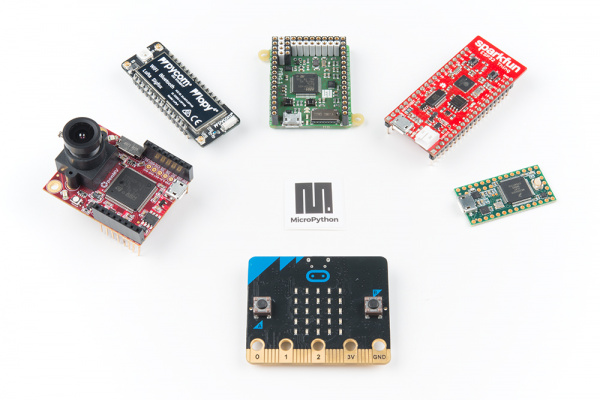
Some development boards, like the pyboard and micro:bit, are capable of running MicroPython out of the box. Others, like the Teensy or ESP32, will require that you load the MicroPython interpreter onto the board first before it will run your MicroPython code.

The more you know! If you are not familiar with an interpreter, it is a program that executes instructions from a programming language without requiring those instructions to be previously compiled into machine language. See this article to learn more.

Boards that run MicroPython

To use this guide, find your development board under the table of contents, navigate to that page, and follow the instructions to get MicroPython working on it.

Python Logo

pyboard

The pyboard is the official board of MicroPython, and it comes packed with a powerful ARM Cortex-M4 microcontroller.

MicroPython pyboard v1.1

MicroPython pyboard v1.1

DEV-14412
$39.95
1

By default, the pyboard comes pre-loaded with the MicroPython interpreter, which means you can get started writing code for it as soon as you pull it out of its adorable case. The basic steps are:

  • Plug the pyboard into your computer, and it should enumerate as a USB mass storage device.
  • Navigate (e.g. using File Explorer or Finder) to the pyboard drive (likely called “PYBFLASH”).
  • Modify main.py with your code and save the file (overwrite the original main.py in the pyboard drive).
  • Eject (unmount) the drive from your operating system (OS).
  • Press the pyboard’s reset (RST) button to start running your program.

If you would like to learn more about the pyboard, read our Pyboard Hookup Guide.

Update Firmware

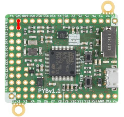
If you want to update the pyboard’s interpreter, you will need to perform some extra steps. To begin, make sure power is disconnected from the pyboard. Use a piece of wire or a jumper to connect the P1 (DFU) and 3V3 pins together (connection is in red below).

pyboard with jumper from 3.3V to DFU pin

Connect the pyboard to an available USB port on your computer. Next, download the firmware file:

  • Find the version of your pyboard (e.g. PYBv1.0 or PYBv1.1), which should be written in white silkscreen on the board.
  • Download the latest .dfu firmware file for your board from the MicroPython downloads page.
    • Make sure you select a firmware from the section that lists your board version (e.g. PYBv1.1).
    • You can see that there are different firmware versions under each pyboard version that have been compiled with different features (floating point, threading, etc.). When in doubt, download the standard firmware, as that is what the pyboard ships with.

With the firmware file downloaded, we will use dfu-util to flash the board with the new firmware. Installing dfu-util differs among operating systems (OS), so see below for your particular OS:

Windows

Windows makes it difficult to install non-signed drivers, so we need to use a special program to do that for us. Download and run the Zadig utility from this site.

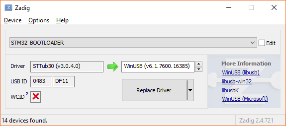
Make sure that your pyboard is plugged in and in DFU mode (e.g. jumper P1 to 3V3). In Zadig, select Options > List All Devices. From the drop-down menu, select STM32 BOOTLOADER. It should recommend replacing the STTub30 driver with WinUSB, which is what we want. If you do not see this, select WinUSB as the replacement driver from the driver menu on the right.

Zadig Windows USB driver utility

Click Replace Driver and you should get a pop-up telling you it was installed successfully. Close out of Zadig.

Next, we’ll need to use dfu-util to upload the firmware. Head to the dfu-util site and download the latest release, which is 0.9 at the time of this writing. Alternatively, you can download dfu-util v0.9 directly by clicking on this link.

Download dfu-util v0.9

Unzip it, open a command prompt, and navigate to the unzipped folder. For example, if you saved and unzipped the file in your Downloads directory, that might be:

language:Batchfile
cd Downloads\dfu-util-0.9-win64\dfu-util-0.9-win64

To upload the firmware to the pyboard, run the following line, replacing <path to .dfu> with the location of the .dfu file you downloaded (for example, it might be in the Downloads folder, which would be something like ..\..\pybv11-20180821-v1.9.4-479-g828f771e3.dfu):

language:Batchfile
dfu-util --alt 0 -D <path to .dfu>

If the firmware was successfully uploaded, you should get a message that ends with done parsing DfuSe file.

Updating the firmware on the pyboard with dfu-util on Windows

macOS and Linux

If you are on macOS, you will need to first install Homebrew. From there, install dfu-util with:

language:shell
brew install dfu-util

If you are on a Debian-based Linux distribution, you can install dfu-util with:

language:shell
sudo apt-get install dfu-util

If neither of those options work, head to the dfu-util homepage to download the package, binaries, or source code.

With the pyboard plugged in and in DFU mode (e.g. jumper P1 to 3V3), run the following command, replacing <path to .dfu> with the location of the .dfu file. For example, this might be ~/Downloads/pybv11-20180821-v1.9.4-479-g828f771e3.dfu.

language:shell
sudo dfu-util --alt 0 -D <path to .dfu>

If the firmware was successfully uploaded, you should get a message that ends with done parsing DfuSe file.

Updating the firmware on the pyboard with dfu-util on Linux

If you are having problems uploading the firmware or have multiple DFU devices plugged into your host machine, see the instructions on the pyboard GitHub repository for more information.

Test It

Even though the pyboard enumerates as a mass storage device (which allows you to modify main.py in its flash memory to write new programs), you can interact with REPL to test some basic commands. REPL stands for read, evaluate, print, loop, and it is essentially a simple, interactive shell that allows you to enter and execute one command at a time.

To communicate REPL, we will use the virtual serial port on our computer. If you are using macOS or Linux, the drivers should be already installed for you.

On macOS, enter the command:

language:shell
ls -l /dev/tty.usbmodem*

Or on Linux, enter the command:

language:shell
ls -l /dev/ttyACM*

You should see a statement showing the existence of the device file associated with pyboard. Write down or copy the full device file name.

On Windows, the story is a little different. Plug your pyboard into an available USB port. Open the Device Manager, and look for Ports (COM & LPT). Expand it, and you should see your pyboard listed. If you see “USB Serial Device,” then the driver is installed and working. If you see a yellow exclamation mark (!), then you will need to install the driver manually. Right-click on the device and select Properties and click Install Driver.

In the pop-up window, select Browse my computer for driver software. Click Browse to open a file explorer, and select the PYFLASH drive. Unless you deleted the flash memory of the pyboard, it should come with the driver .inf file stored in its flash.

Select the pyboard's flash drive

Click OK and Next, and the driver should be installed for you. When it’s done, you should see USB Serial Device listed under Ports (COM & LPT). You will also want to write down or copy the COM name (e.g. COM6). If you need further help with installing the driver on Windows, see this document.

pyboard as a serial device in Windows

Regardless of your OS, download and install a serial terminal program for your operating system. Open it, and start a new serial connection with the COM name or device file location and a baud rate of 115200.

Connecting to REPL on the pyboard

Press the enter key to get a REPL command prompt (>>>). Enter the following commands:

language:python
import pyb
led = pyb.LED(1)
led.on()

This should turn on one of the LEDs on the pyboard.

Using REPL on the pyboard to control an LED

Enter the following command to turn it off:

language:python
led.off()

If you are able to control the LED, it means that MicroPython is up and running on your pyboard!

ESP32 Thing

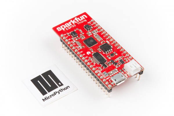
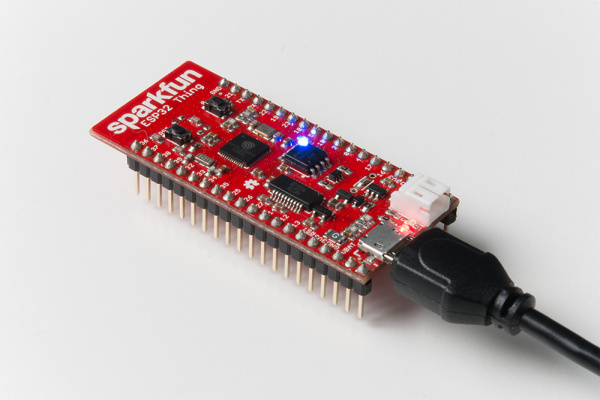
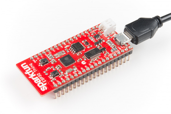
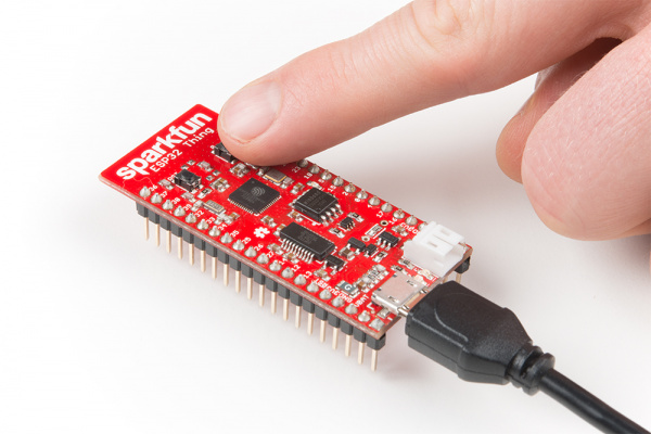
The SparkFun ESP32 Thing is based around Espressif’s powerful ESP32 chip. It includes onboard WiFi and Bluetooth radios, making it a perfect endpoint platform for Internet of Things (IoT) products and projects.

Note: At the time of this writing, the Bluetooth stack does not work with MicroPython on the ESP32
SparkFun ESP32 Thing

SparkFun ESP32 Thing

DEV-13907
$19.95
57

By default, the ESP32 Thing comes with the Arduino bootloader pre-installed. To get it to work with MicroPython, we will need to perform some extra steps.

Install FTDI Drivers

To communicate with the ESP32, the Thing board has an FTDI FT231x USB-to-Serial chip. Most versions of Linux and macOS come with the drivers necessary to talk to this chip. Windows users will need to install special drivers. If you need to install the drivers, refer to our How to Install FTDI Drivers tutorial.

To check if your driver is working, plug in your ESP32 Thing board into an available USB port (and make sure no other development boards or USB-to-Serial boards are plugged in).

On Windows, open up the Device Manager, and look for the Ports category. Expand it, and if you see something labeled USB Serial Port, it means your FTDI driver is working properly.

FTDI driver working on Windows

On macOS, enter the command:

language:sh
ls -l /dev/tty.usb*

Or on Linux, enter the command:

language:sh
ls -l /dev/ttyUSB0

You should see a statement showing the existence of the /dev/tty.usbserial (or /dev/ttyUSB0) file. If you see “No such file or directory,” that means the driver was not installed. If you run into any issues with drivers in Linux or macOS, refer to the FTDI VCP drivers page for more information.

Download the Latest MicroPython Firmware

Head to the MicroPython downloads page and download the latest “firmware for ESP32 boards.” You will want the .dfu file listed under standard firmware.

Install Python

To install MicroPython on the ESP32, we need to install full Python on our host machine. Weird, right? As it turns out, the esptool is a Python script that we’ll run to upload the MicroPython interpreter to the ESP32.

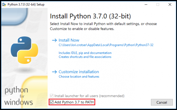
Head to python.org and download the latest Python for your operating system. The esptool reportedly works with Python 2.7 and Python 3.4 (or newer). Follow the directions to install Python on your computer.

Install esptool

Open a command prompt and enter the following line:

language:shell
pip install --upgrade esptool

The pip utility should automatically download and install esptool for you.

Installing esptool

Flash MicroPython

Make sure your ESP32 is plugged into your computer. If you are on Windows, open the Device Manager and find out which COM port or device file your ESP32 is associated with (mine is COM7 as per the image above).

Before flashing the firmware to the ESP32, we’ll want to erase everything in the chip’s flash memory. To that, enter the following command (replace <USB-to-Serial Port> with your particular port name, such as COM7 on Windows, /dev/tty.usbserial-<letters and numbers> on macOS, or /dev/ttyUSB0 on Linux):

language:shell
esptool.py --chip esp32 -p <USB-to-Serial Port> erase_flash

You should see some output explaining that the ESP32 has been erased and reset.

Erasing flash on the ESP32

Next, flash the firmware with the following command (replace <USB-to-Serial Port> with your particular port name, and replace <path to .bin> with the location of your downloaded firmware file, such as ~/Downloads/esp32-20180822-v1.9.4-479-g828f771e3.bin):

language:shell
esptool.py --chip esp32 -p <USB-to-Serial Port> write_flash -z 0x1000 <path to .bin>

Once the firmware has been uploaded, you should see the message: “hash of data verified.”

Uploading MicroPython to the ESP32

At this point, your ESP32 Thing should be running MicroPython.

Test It

Download and install one of the many available serial terminal programs. If you are on Windows, open the Device Manager and find out which COM port your ESP32 Thing is associated with (for example, COM7). On macOS, it will likely be /dev/cu.usbserial-<some letters/numbers>, and on Linux, it’s probably something like /dev/ttyUSB0.

Open up your serial terminal program, and connect to your ESP32 Thing using the associated serial port and a baud rate of 115200. Press the enter key, and you should be presented with the MicroPython REPL command prompt (>>>). Enter the following commands:

language:python
from machine import Pin
led = Pin(5, Pin.OUT)
led.value(1)

This should turn on the LED attached to pin 5 on the ESP32 Thing board.

Turn on LED on ESP32 with MicroPython

To turn off the LED, enter the following command:

language:python
led.value(0)

This simple test shows that you can control the ESP32 pins with MicroPython. You should be ready to start programming!

Teensy 3.x

The Teensy is development platform that easily fits on a breadboard, can be programmed with the Arduino IDE, and offers many advanced features over most basic Arduino boards. It is well-loved among many embedded engineers and hobbyists for its powerful microcontroller while still being relatively inexpensive.

Teensy 3.2

Teensy 3.2

DEV-13736
$19.80
61

As of the time of this writing, MicroPython is compatible with the following Teensy boards:

Heads up! A MicroPython build for the Teensy is not actively maintained by the MicroPython community. That means you will need to install the ARM toolchain and compile the MicroPython interpreter yourself. As a result, this is recommended for advanced users only!

Note that while it is possible to install the ARM toolchain and build MicroPython on Windows, the instructions and scripts were written for Linux. As a result, they might work on macOS, and to use them on Windows, you will need something like the Cygwin environment. For now, the steps will be shown for Linux only (and only for certain Debian variants).

Note: These steps were tested with Ubuntu 18.04.

Install the ARM Toolchain

In a terminal, enter the following commands:

language:shell
sudo add-apt-repository ppa:team-gcc-arm-embedded/ppa
sudo apt-get update
sudo apt-get install -y gcc-arm-embedded

This should install the GCC ARM Embedded toolchain.

If you run unto any problems or want to download the packages (or source code), head to GNU Arm Embedded Toolchain page.

Build MicroPython for Teensy

Download the latest ZIP file from the MicroPython GitHub repository:

language:shell
wget https://github.com/micropython/micropython/archive/master.zip

Unzip the repository and navigate to the Teensy port directory:

language:shell
unzip master.zip
cd micropython-master/ports/teensy

Determine which Teensy board you are using (MicroPython has thus far only been ported to the Teensy 3.x variants). The BOARD argument will be set to one of the following:

  • For Teensy 3.1 or 3.2, use TEENSY_3.1
  • For Teensy 3.5, use TEENSY_3.5
  • For Teensy 3.6, use TEESNY_3.6

Since I tested this process with a Teensy 3.2 board, I will show TEENSY_3.1 in the following commands. Replace TEENSY_3.1 with the argument for your particular board.

language:shell
make BOARD=TEENSY_3.1

If you wish to create MicroPython build for a different board, call make clean first before calling make BOARD=TEENSY_3.x again.

For more information on how to build MicroPython for the Teensy, see the MicroPython Teensy wiki page.

Build the Teensy Flashing Tool

To upload the build MicroPython interpreter to the Teensy, we will use Paul Stroffregen’s teensy_loader_cli tool (the repository for which can be found here). We need to download the repository, make it, and install it.

To start, install the libusb library:

language:shell
sudo apt-get install -y libusb-dev

If you have not already done so, head back to your home directory and delete the MicroPython master.zip file:

language:shell
cd ~
rm master.zip

Download and build the tool:

language:shell
wget https://github.com/PaulStoffregen/teensy_loader_cli/archive/master.zip
unzip master.zip
cd teensy_loader_cli-master
make

Install the tool to the local user’s application directory:

language:shell
sudo cp teensy_loader_cli /usr/local/bin

Flash the Teensy

To avoid having to use sudo to upload programs to the Teensy, install the following udev rule:

language:shell
cd ~
wget http://www.pjrc.com/teensy/49-teensy.rules
sudo cp 49-teensy.rules /etc/udev/rules.d/
sudo udevadm control --reload-rules

Plug in your Teensy board to an available USB port (if it was already plugged in, unplug it first to allow udev to see it after reloading the new udev rules).

To flash the MicroPython firmware, determine which board you have and use the microcontroller name as the mcu argument for teensy_loader_cli:

  • For Teensy 3.1 or 3.2, use mk20dx256
  • For Teensy 3.5, use mk64fx512
  • For Teensy 3.6, use mk66fx1m0

Finally, we flash the built MicroPython firmware. Note that as I am using the Teensy 3.2 board, I will use mk20dx256 as the mcu argument. Change it to match your Teensy board.

language:shell
cd micropython-master/ports/teensy
teensy_loader_cli --mcu=mk20dx256 -w build/micropython.hex

After entering that last command, your terminal should wait for your Teensy to show up in bootloader mode. With the Teensy plugged in to your computer, press the reset button on the Teensy. After a few seconds, the Teensy’s LED should flash twice rapidly, and the teensy_loader_cli command should finish executing in the terminal.

MicroPython should now be installed on your Teensy!

Test It

Install the minicom utility:

language:shell
sudo apt-get install minicom

Open a serial connection to REPL running on the Teensy:

language:shell
minicom -D /dev/ttyACM0 -b 115200

Press enter once to see the REPL command prompt (>>>). Enter the following commands:

language:python
import pyb
led = pyb.Pin.board.LED
led.value(1)

This should turn on the Teensy’s LED. Turn it off with:

language:python
led.value(0)

Blinking the LED on a Teensy board with MicroPython

Exit out of minicom by pressing Ctrl+A followed by pressing X. Press enter when you are asked if you really want to leave.

micro:bit

When it comes to the micro:bit, MicroPython is a great alternative to the graphical programming found on MakeCode, and it can be a good introduction to text-based programming (especially for students).

micro:bit Go Bundle

micro:bit Go Bundle

DEV-14336
$16.50
12

Loading MicroPython on to the micro:bit is easy. There are two main editors available: the Python online editor on microbit.org and the offline Mu editor application. The general idea is that your MicroPython code is bundled with the MicroPython interpreter in one file that gets uploaded to the micro:bit. As a result, we don’t need to perform any special steps to load the MicroPython interpreter onto the micro:bit.

Online Editor

Head to python.microbit.org. You should see some default code. If not, copy in the following:

language:python
# Add your Python code here. E.g.
from microbit import *

while True:
    display.scroll('Hello, World!')
    display.show(Image.HEART)
    sleep(2000)

Click the Download button, and your computer should download a microbit.hex file (combination of MicroPython interpreter and your code).

Writing MicroPython code in the online editor for the micro:bit

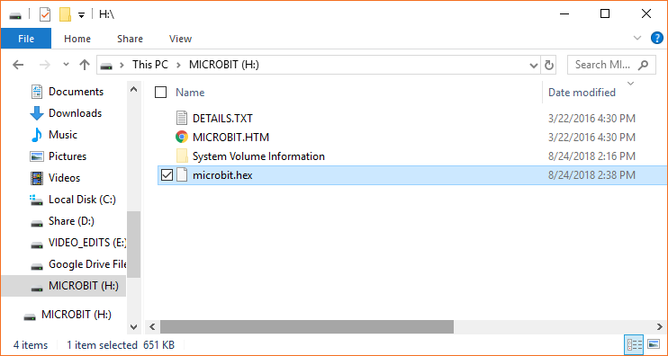
Plug in your micro:bit into an available USB port on your computer, and it should enumerate as a storage device (e.g. similar to a USB flash drive). Open a file explorer (or Finder), locate the downloaded .hex file, and copy it into the root directory of the micro:bit’s drive.

Copying a .hex file to the micro:bit

Your micro:bit should automatically reboot and begin scrolling “Hello, World!” followed by a heart image.

Mu

Download and install Mu from codewith.mu. Open the editor, and copy in the following code:

language:python
# Add your Python code here. E.g.
from microbit import *

while True:
    display.scroll('Hello, World!')
    display.show(Image.HEART)
    sleep(2000)

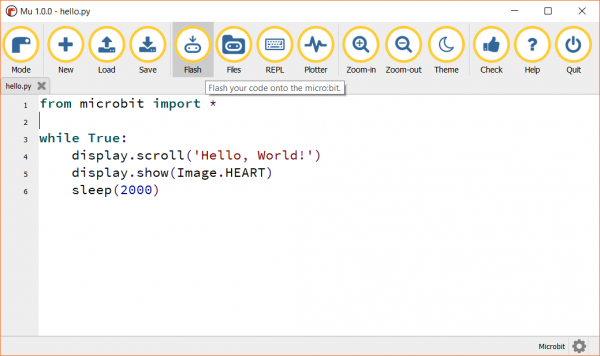
With the micro:bit plugged into your computer, press the Flash button to upload the code.

Flashing the micro:bit with code from the Mu editor

Your micro:bit should begin scrolling the phrase “Hello, World!” followed by a heart image.

Interacting with REPL

If you are on Windows, you will need to download and install the mbed serial driver. Follow the instructions on this site to download the driver executable. Note that you will need to have the micro:bit plugged in when you run the driver install program.

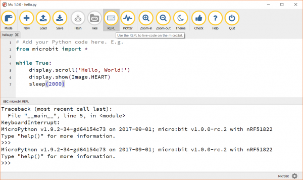
If you are using Mu, you can simply click the REPL button to bring up an interactive REPL terminal in the editor. This works even if you are running a program on the micro:bit.

REPL on micro:bit with Mu

If you are using the online editor, you will need to first upload a blank program to the micro:bit (i.e. delete all the code in the editor, download a .hex file, and copy it to the micro:bit). Most code will cause the micro:bit to stop responding to serial events, so we upload a blank program to prevent this. You can use a Serial terminal program to interact with REPL.

Windows

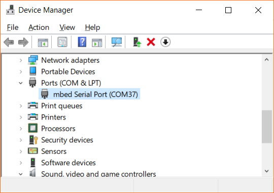
Open up the Device Manager, and look for the Ports category. Expand it, and note the COM number listed next to mbed Serial Port.

Finding your port number in the Device Manager

Using a serial terminal program (such as PuTTY or Tera Term), connect to the micro:bit using your COM port (e.g. COM37) and a baud rate of 115200.

macOS

Plug in the micro:bit and open a terminal. Enter the following command:

language:shell
ls /dev/cu.*

You should see a list of serial devices; look for the one with usbmodem (e.g. /dev/cu.usbmodem1422). Use the screen or minicom commands to open a serial connection with the microbit. For example (replace usbmodem1422 with the device file associated with your micro:bit):

language:shell
screen /dev/cu.usbmodem1422 115200

Linux

Install a serial terminal program, such as screen or minicom. Plug in your micro:bit and find the name of its associated device file with:

language:shell
dmesg | tail

You should see that the micro:bit was assigned to a particular file, such as /dev/ttyUSB0). Connect to the micro:bit with the device file (replacing ttyUSB0 with the name of the device file associated with your micro:bit) and a baud rate of 115200:

language:shell
screen /dev/ttyUSB0 115200

You can use any number of other serial terminal programs instead of screen, if you wish.

Test It

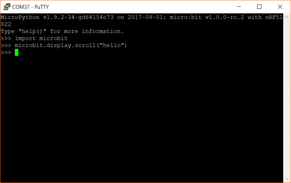
In your serial terminal program, you should see the REPL prompt (>>>). Enter the following commands:

language:python
import microbit
microbit.display.scroll("hello")

Interacting with the micro:bit REPL over a serial connection

You should then see the word “hello” flash across your LED array!

Pycom LoPy4

The Pycom LoPy4 is a combination of wireless radios (WiFi, Bluetooth, LoRa, SigFox) and a MicroPython development platform that helps users get started making their own Internet of Things (IoT) endpoints.

Pycom LoPy4 Development Board

Pycom LoPy4 Development Board

WRL-14674
$47.95
1
Note: The LoPy4 is capable of running MicroPython out of the box. If you would like to update the firmware on the LoPy4, see the instructions below.

Update Firmware

To load firmware onto the LoPy4, you will need to purchase a Pycom Expansion Board 3.0.

While it’s not required, Pycom recommends that you update the firmware on the Expansion Board by following these steps.

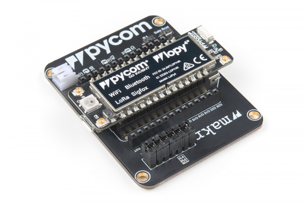
With the Expansion Board disconnected from your computer, connect the LoPy4 to the expansion board, and then plug in a USB cable to the Expansion Board.

Pycom LoPy4 on an Expansion Board 3.0

Navigate to Pycom’s Updating Firmware page and download the firmware tool for your operating system (links at the top of the page). Run the program and follow the instructions to install Pycom’s firmware update tool.

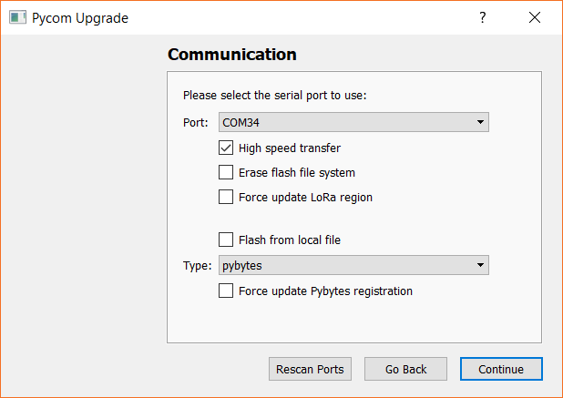
Run the tool, and follow the on-screen instructions to connect to your LoPy4 board. Make sure that the serial port is selected correctly (leave the other options as default).

Updating the MicroPython firmware on the LoPy4

If you would like to use the Pybytes IoT platform, head to the Pybytes site, make an account, and copy in the activation key when asked. Otherwise, feel free to skip that step (the firmware will install regardless of whether you provided a Pybytes key or not).

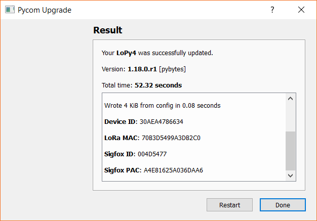
Once the update is complete, you should see a “successfully updated” message.

Successfully updated firmware on the LoPy4

Test It

Download and install a serial terminal program of your choosing. If you are on Windows, open the Device Manager and find out which COM port your LoPy4 is associated with (mine is COM34). On macOS, it will likely be /dev/cu.usbserial-<some letters/numbers>, and on Linux, it’s probably something like /dev/ttyUSB0.

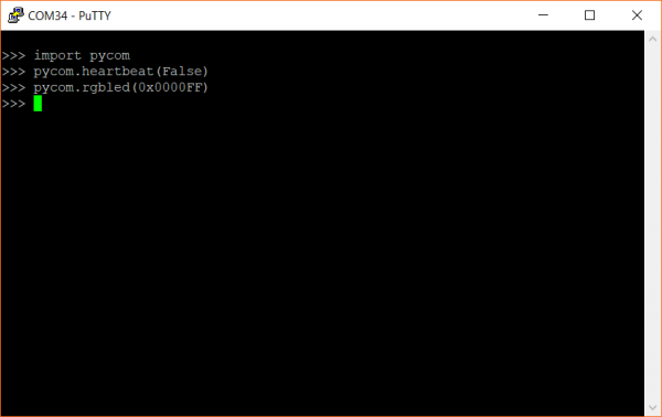
Open up your serial terminal program, and connect to your LoPy4 using the associated serial port and a baud rate of 115200. Press the enter key, and you should be presented with the MicroPython REPL command prompt (>>>). Enter the following commands:

language:python
import pycom
pycom.heartbeat(False)
pycom.rgbled(0x0000FF)

This should turn the onboard LED to blue.

MicroPython on the Pycom LoPy4

Enter the following command to turn it off:

language:python
pycom.rgbled(0x000000)

If you were able to turn the LED on and off, it means that MicroPython is running on your Pycom board! Pycom also makes a plugin named Pymakr for the Atom and Visual Studio Code IDEs that you can use to develop MicroPython for the LoPy4 (and other Pycom boards). To learn more about Pymakr, see this page. Pycom has a MicroPython example for Pymakr that you can see here to help you get started.

OpenMV M7 Camera

The OpenMV M7 is a development platform with an integrated camera that lets you create computer vision projects. Out of the box, it comes loaded with the MicroPython interpreter, so you don’t need to load anything onto the M7.

OpenMV M7 Camera

OpenMV M7 Camera

SEN-14632
$65.00
4

Update Firmware

OpenMV recommends that you use the OpenMV IDE to develop applications for the M7, which is probably a good thing, considering it allows you to make updates to your code while and watch a live camera feed. If you would like to update the firmware (which includes the MicroPython interpreter), it is recommended that you do so through the OpenMV IDE.

Head to the OpenMV Downloads page and click to download the IDE for your operating system. Install it, accepting all the default options. If you are on Windows, you will likely be asked to install one or more USB drivers.

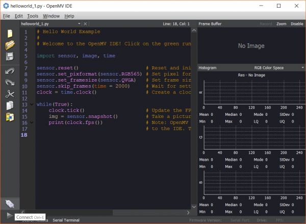
Open the OpenMV IDE and connect the M7 to your computer. Click the Connect button in the bottom-left corner of the IDE to open a connection to your M7.

OpenMV IDE connect button

Make sure your computer is connected to the Internet, and if your M7’s firmware is out of date, you’ll get a pop-up asking you to update it. Click OK to automatically start the update process. If you don’t want to save any files that you’ve stored on the M7, click Yes when asked about erasing the internal file system (otherwise, click No).

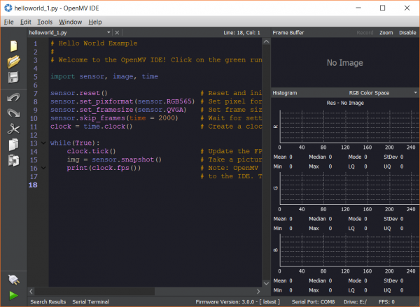
Once the flashing process is complete, you should see that the reported firmware (bottom right of the IDE) has been updated to reflect the most recent version (it should also say [ latest ]).

OpenMV IDE showing latest firmware version

Test It

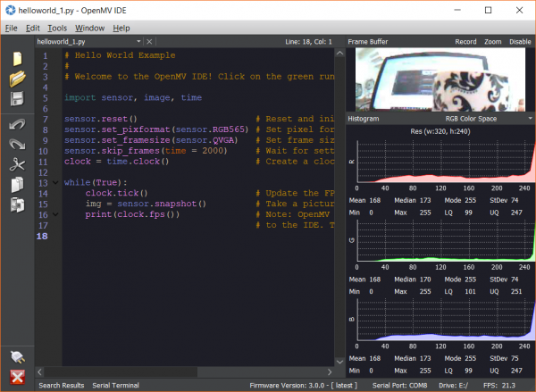
By far the easiest way to begin developing on the M7 is to use the OpenMV IDE. When you first open it, you should see some example code (named helloworld_1.py). Click the Play button (bottom left of the IDE), and you should get a live video stream from the camera (don’t forget to remove the lens cap!) along with real-time color histogram updates.

Live video feed from the OpenMV M7

If you don’t want to use the OpenMV IDE, then there are a number of ways you can interact with the camera. The first is by opening up a file explorer/finder and browsing to the enumerated drive while the M7 is plugged in (likely called USB DRIVE). Here, you will find a few files that reside in the M7’s flash memory. If you modify main.py, you can change the code that runs on the M7. When you save changes (overwriting the original main.py), the M7 will automatically restart and begin running the code in main.py.

Alternatively, you can open a serial connection to the M7 using your choice of serial terminal programs. Find the device port number or device file (for example, Device Manager in Windows might show something like COM8, macOS might show /dev/cu.usbserial-<some letters/numbers>, or Linux might show /dev/ttyUSB0). Open a connection with a baud rate of 115200, and press enter to see the MicroPython REPL command prompt (>>>).

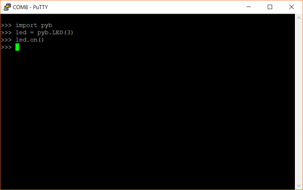
Enter the following commands:

language:python
import pyb
led = pyb.LED(3)
led.on()

This should turn on the blue LED on the M7.

Testing MicroPython on the OpenMV M7

Enter the following command to turn the LED off:

language:python
led.off()

This should hopefully show you the various ways to interact with the MicroPython interpreter on the OpenMV M7! To learn more about how to use the M7, see OpenMV’s documentation page located at docs.openmv.io.

Resources and Going Further

MicroPython can be a great way to dive into programming on an embedded system (especially if you know Python already) or if you want to quickly make a project or prototype. If you want to dig deeper into MicroPython, here are some resources to help you out:

pyboard links:

ESP32 Thing links:

Teensy 3.x links:

micro:bit links:

Pycom LoPy4 links:

OpenMV M7 Camera links:

Python Logo

Looking to develop something with MicroPython? Check out these guides to get you started:

Pyboard Hookup Guide

Getting started with the Pyboard using MicroPython.

learn.sparkfun.com | CC BY-SA 3.0 | SparkFun Electronics | Niwot, Colorado

I2S Audio Breakout Hookup Guide

$
0
0

I2S Audio Breakout Hookup Guide a learn.sparkfun.com tutorial

Available online at: http://sfe.io/t802

Introduction

The I2S Audio Breakout board uses the MAX98357A digital to analog converter (DAC), which converts I2S (not be confused with I2C) audio to an analog signal to drive speakers. The MAX98357A has a built in class D amplifier which can deliver up to 3.2W of power into a 4Ω load. For more information, see the Hardware Overview section below.

SparkFun I2S Audio Breakout - MAX98357A

SparkFun I2S Audio Breakout - MAX98357A

DEV-14809
$4.95

Suggested Tools

You will need a soldering iron, solder, general soldering accessories, screw driver, and hobby knife.

Weller WE1010 Soldering Station

Weller WE1010 Soldering Station

TOL-14734
$129.00
Solder Lead Free - 100-gram Spool

Solder Lead Free - 100-gram Spool

TOL-09325
$7.95
7
Pocket Screwdriver Set

Pocket Screwdriver Set

TOL-12891
$3.95
3
Hobby Knife

Hobby Knife

TOL-09200
$2.95
2

Suggested Reading

If you aren’t familiar with the following concepts, we recommend checking out these tutorials before continuing.

How to Solder: Through-Hole Soldering

This tutorial covers everything you need to know about through-hole soldering.

How to Power a Project

A tutorial to help figure out the power requirements of your project.

Switch Basics

A tutorial on electronics' most overlooked and underappreciated component: the switch! Here we explain the difference between momentary and maintained switches and what all those acronyms (NO, NC, SPDT, SPST, ...) stand for.

ESP32 Thing Hookup Guide

An introduction to the ESP32 Thing's hardware features, and a primer on using the WiFi/Bluetooth system-on-chip in Arduino.

How to Work w/ Jumper Pads and PCB Traces

Handling PCB jumper pads and traces is an essential skill. In this tutorial, you will learn how to cut a PCB trace and add a solder jumper between pads to reroute connections. You will also learn how to repair a trace with the green wire method if a trace is damaged.

ESP32 Thing Motion Shield Hookup Guide

Getting started with the ESP32 Thing Motion Shield to detect movements using the on-board LSM9DS1 IMU and adding a GPS receiver. Data can be easily logged by adding an microSD card to the slot.

Hardware Overview

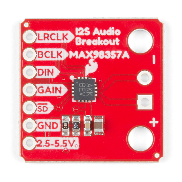
The I2S audio breakout converts the digital audio signals using the I2S standard to an analog signal and amplifies the signal using a class D amplifier. The board can be configured to output only the left channel, right channel, or both. For more information about how to configure the board, refer to the Jumper Selection section below.

I2S Audio Breakout Board Top View

Board Specs

ParameterDescription
Supply Voltage Range2.5V - 5.5V.
Output Power3.2W into 4Ω at 5V.
Output Channel SelectionLeft, Right, or Left/2 + Right/2 (Default).
Sample Rate8kHz - 96kHz.
Sample Resolution16/32 bit.
Quiescent Current2.4mA.
Additional FeaturesFilterless Class D outputs, no MCLK required, click and pop reduction, short-circuit and thermal protection.

Pin Descriptions

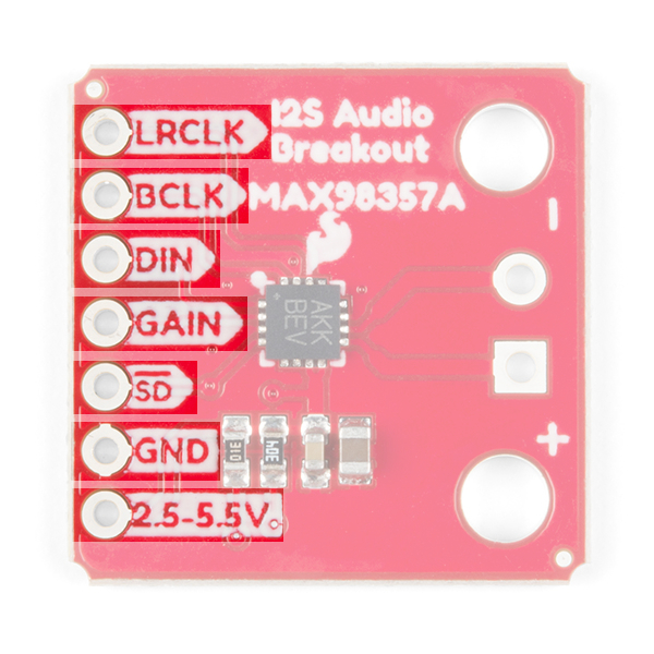
The SparkFun I2S audio breakout board is fairly simple, requiring only a few pin connections to get the board working.

Highlight of Input Connections

Inputs

Pin LabelDescription
LRCLKFrame clock (left/right clock) input.
BCLKBit clock input.
DINSerial data input.
GAINGain setting. Can be set to +3/6/9/12/15dB. Set to +9dB by default.
SDShutdown and channel select. Pull low to shutdown, or use the jumpers to select the channel output (see jumper selection for more information).
GNDConnect to ground
VDDPower input. Must be between 2.5 and 5.5VDC.

Outputs

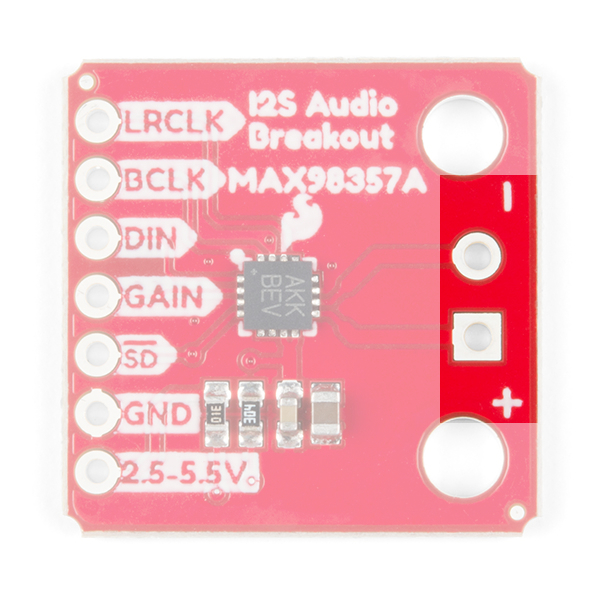
The output is where you’ll connect your speaker.

Highlight of Output Connections

Pin LabelDescription
+Positive speaker output.
-Negative speaker output.

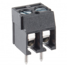
Speaker wire can either be soldered directly to the output pads, but if screw terminals are more your style, you can use our 3.5mm screw terminals.

Screw Terminals 3.5mm Pitch (2-Pin)

Screw Terminals 3.5mm Pitch (2-Pin)

PRT-08084
$0.95

Jumper Selection

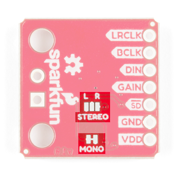
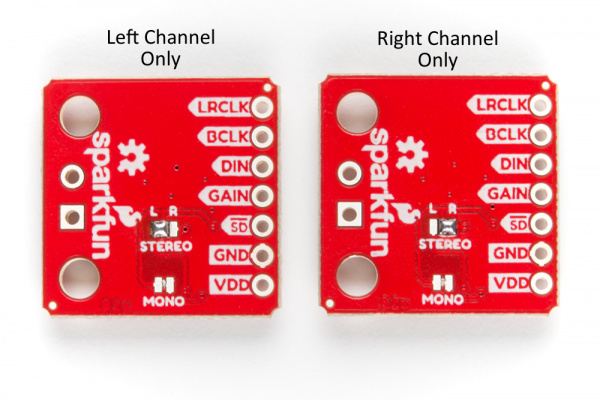
By default the board is configured in “mono” operation, meaning the left and right signals are combined together to drive a single speaker.

Highlight Of Jumper Selection

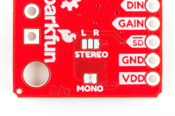
If you want a separate speaker for the left and right audio channels you’ll first need to cut the mono jumper as pictured below.

Mono Trace Jumper Cut

To configure the board to respond to a specific audio channel, you’ll need to close the stereo jumper as shown below.

Single Channel Select Jumper

Gain Selection

In addition to being able to select the audio channel output, the gain can also be configured in a few ways. The gain of the amplifier can be configured from as low as +3dB to as high as +15dB. While the channel selection can be configured on board, the gain however is controlled externally using the gain pin. By default, the board is configured for +9dB, but can be changed using the table below.

Gain (dB)Gain Pin Connection
15Connected to GND through a 100kΩ resistor.
12Connected to GND.
9Unconnected (Default).
6Connected to VDD.
3Connected to VDD through a 100kΩ resistor.

Examples

Note: These example assumes you are using the latest version of the Arduino IDE on your desktop. If this is your first time using Arduino, please review our tutorial on installing the Arduino IDE. If you have not previously installed an Arduino library, please check out our installation guide.

This board should work with any microcontroller or single board computer that has I2S capable pins. In these examples, we’re going to look at a pretty powerful library that allows you to use an ESP32 Thing to play audio from a wide variety of sources. First, we’ll play an audio file which is stored in the ESP32’s program memory, and once we have that working we’ll look at creating a MP3 trigger. The following libraries are needed to run the examples that were originally written for the ESP8266, but also work with the ESP32.

ESP8266Audio Arduino Library

You’ll need to install the ESP8266 Audio Arduino Library, written by Earle F. Philhower, which you can get from the link below. This library will allow you to play a wide variety of audio formats including: AAC, FLAC, MIDI, MOD, MP3, RTTTL, and WAV. To use the library, you can add the library from Arduino by selecting Sketch >Include Library >Add .ZIP Library… and selecting the .zip file from wherever you store your file downloads.

ESP8266 Audio Library (ZIP)

ESP8266_Spiram Arduino Library

The ESP8266 Audio library depends on the ESP8266 Spiram library, written by Giancarlo Bacchio, which will also need to be downloaded. You can download the library from the link below. Installing the library follows the same process as outlined above.

ESP8266 Spiram Library (ZIP)

First Test

In this first example, we’ll run a quick example sketch to make sure the I2S audio breakout board is wired correctly and is working.

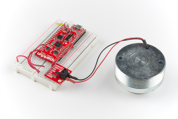
ESP32 Connected to I2S Breakout Board

Required Materials

The parts used in this example are listed in the wishlist below. You may not need everything though depending on what you have. Add it to your cart, read through the example, and adjust the cart as necessary.

Hookup Table

The connections that need to be made to the ESP32 are list below.

ESP32 PinI2S Audio Breakout Pin
VUSB/3V3VDD
GNDGND
GPIO 22DIN
GPIO 26BCLK
GPIO 25LRCLK

Make sure to also connect a speaker to the I2S audio breakout board’s output pins.

Example Code

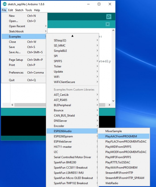
We’re going to use one of the examples that comes with the library named “PlayAACFromPROGMEM”. With the library installed, open the example located in: File>Examples>ESP8266Audio>PlayAACFromPROGMEM .

Where to find Example Sketch "PlayAACFromPROGMEM"

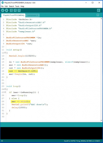
Before we upload the code, we’re going to add two lines of code (as highlighted in the image below). The first line is going to adjust the volume, which we add after we initialize the I2S output (out = new AudioOutputI2S();). After the output is initialized, we’re going to add out -> SetGain(0.125);. As the name suggests this sets the gain of the output, which takes a floating point number and has a maximum value of 4.0. The second line will reduce hum at the end of the audio clip by adding aac -> stop(); in the else statement in the main loop(). After you upload the sketch to your ESP32, you should hear Homer Simpson’s thoughts of perpetual motion machines if everything is working.

Hightlight of changes made to the example sketch

ESP32 MP3 Trigger

Now that we know the board is working, let’s take it up a notch. In this next example, we’ll create a MP3 trigger that works similar to our MP3 Trigger.

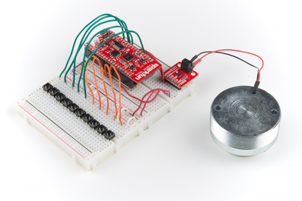
ESP32 Connected to I2S Breakout and pushbuttons

Required Materials

For this example, we’ll need to add a few more parts to the ones we used in the previous example (including a second breadboard). You may not need everything though depending on what you have. Add it to your cart, read through the example, and adjust the cart as necessary.

Before we add code, we’ll need some audio files to play. Any MP3 audio file should work, you’ll just need to copy them over to your microSD card using a microSD USB Reader. Before ejecting the microSD card from your computer, make sure to relabel the files TRACKn.mp3, where n is a integer number between 0-9. The I2S audio breakout board has the same pin connections as the previous example, but this time we’re going to change the audio source from PROGMEM to our microSD card. The last step before adding the code below, is to add headers to the ESP32 Thing, as well as the Motion Shield, as outlined in the hookup guide.

language:c
/* SparkFun I2S Audio Breakout Demo
 * Created by: Alex Wende
 * 8/3/2018
 * 
 * Uses a ESP32 Thing to create a MP3 trigger using 
 * the I2S Audio Breakout board.
 * 
 * Parts you'll need:
 * - I2S Audio Breakout board (https://www.sparkfun.com/products/14809)
 * - ESP32 Thing (https://www.sparkfun.com/products/13907)
 * - Micro SD Breakout (https://www.sparkfun.com/products/544)
 * - A microSD card (https://www.sparkfun.com/products/13833)
 * - Speaker (4-8ohms)
 * 
 * The following libraries need to be installed before
 * uploading this sketch:
 * - ESP8266 Audio (https://github.com/earlephilhower/ESP8266Audio)
 * - SRam Library (https://github.com/Gianbacchio/ESP8266_Spiram)
 */

#include <Arduino.h>
#include "AudioGeneratorMP3.h"
#include "AudioOutputI2S.h"
#include "AudioFileSourceSD.h"
#include "driver/i2s.h"
#include <SD.h>

//define trigger pins
#define TRIGGER0 13
#define TRIGGER1 12
#define TRIGGER2 14
#define TRIGGER3 27
#define TRIGGER4 32
#define TRIGGER5 5
#define TRIGGER6 15
#define TRIGGER7 2
#define TRIGGER8 0
#define TRIGGER9 4

//Initialize ESP8266 Audio Library classes
AudioGeneratorMP3 *mp3;
AudioFileSourceSD *file;
AudioOutputI2S *out;

volatile bool playing = 0;
volatile byte loadTrack = 0;

//External Interrupt function with software switch debounce
void IRAM_ATTR handleInterrupt()
{
  static unsigned long last_interrupt_time = 0;
  unsigned long interrupt_time = millis();
  // If interrupts come faster than 200ms, assume it's a bounce and ignore
  if (interrupt_time - last_interrupt_time > 200) 
  {
    //Figure out which switch was triggered, and which track to play
    if(!digitalRead(TRIGGER0)) loadTrack = 1;
    else if(!digitalRead(TRIGGER1)) loadTrack = 2;
    else if(!digitalRead(TRIGGER2)) loadTrack = 3;
    else if(!digitalRead(TRIGGER3)) loadTrack = 4;
    else if(!digitalRead(TRIGGER4)) loadTrack = 5;
    else if(!digitalRead(TRIGGER5)) loadTrack = 6;
    else if(!digitalRead(TRIGGER6)) loadTrack = 7;
    else if(!digitalRead(TRIGGER7)) loadTrack = 8;
    else if(!digitalRead(TRIGGER8)) loadTrack = 9;
    else if(!digitalRead(TRIGGER9)) loadTrack = 10;
    playing = 1;
  }
  last_interrupt_time = interrupt_time;
}

void setup()
{  
  Serial.begin(115200);

  //Configure trigger pins to inputs with internal pull-up resistors enabled
  pinMode(TRIGGER0,INPUT_PULLUP);
  pinMode(TRIGGER1,INPUT_PULLUP);
  pinMode(TRIGGER2,INPUT_PULLUP);
  pinMode(TRIGGER3,INPUT_PULLUP);
  pinMode(TRIGGER4,INPUT_PULLUP);
  pinMode(TRIGGER5,INPUT_PULLUP);
  pinMode(TRIGGER6,INPUT_PULLUP);
  pinMode(TRIGGER7,INPUT_PULLUP);
  pinMode(TRIGGER8,INPUT_PULLUP);
  pinMode(TRIGGER9,INPUT_PULLUP);

  //Create interrupts for each trigger
  attachInterrupt(digitalPinToInterrupt(TRIGGER0),handleInterrupt,FALLING);
  attachInterrupt(digitalPinToInterrupt(TRIGGER1),handleInterrupt,FALLING);
  attachInterrupt(digitalPinToInterrupt(TRIGGER2),handleInterrupt,FALLING);
  attachInterrupt(digitalPinToInterrupt(TRIGGER3),handleInterrupt,FALLING);
  attachInterrupt(digitalPinToInterrupt(TRIGGER4),handleInterrupt,FALLING);
  attachInterrupt(digitalPinToInterrupt(TRIGGER5),handleInterrupt,FALLING);
  attachInterrupt(digitalPinToInterrupt(TRIGGER6),handleInterrupt,FALLING);
  attachInterrupt(digitalPinToInterrupt(TRIGGER7),handleInterrupt,FALLING);
  attachInterrupt(digitalPinToInterrupt(TRIGGER8),handleInterrupt,FALLING);
  attachInterrupt(digitalPinToInterrupt(TRIGGER9),handleInterrupt,FALLING);

  out = new AudioOutputI2S();
  mp3 = new AudioGeneratorMP3();

  delay(1000);
  Serial.print("Initializing SD card...");
  if (!SD.begin(33))
  {
    Serial.println("initialization failed!");
    return;
  }
  Serial.println("initialization done.");
  delay(100);
}

void loop()
{
  if(loadTrack) //Load the track we want to play
  {
    //Stop the current track if playing
    if(playing && mp3->isRunning()) mp3->stop();

    if(loadTrack == 1) file = new AudioFileSourceSD("/TRACK0.mp3");
    else if(loadTrack == 2) file = new AudioFileSourceSD("/TRACK1.mp3");
    else if(loadTrack == 3) file = new AudioFileSourceSD("/TRACK2.mp3");
    else if(loadTrack == 4) file = new AudioFileSourceSD("/TRACK3.mp3");
    else if(loadTrack == 5) file = new AudioFileSourceSD("/TRACK4.mp3");
    else if(loadTrack == 6) file = new AudioFileSourceSD("/TRACK5.mp3");
    else if(loadTrack == 7) file = new AudioFileSourceSD("/TRACK6.mp3");
    else if(loadTrack == 8) file = new AudioFileSourceSD("/TRACK7.mp3");
    else if(loadTrack == 9) file = new AudioFileSourceSD("/TRACK8.mp3");
    else if(loadTrack == 10) file = new AudioFileSourceSD("/TRACK9.mp3");

    out -> SetGain(0.08); //Set the volume
    mp3 -> begin(file,out); //Start playing the track loaded
    loadTrack = 0;
  }

  if(playing && mp3->isRunning()) {
    if (!mp3->loop())
    {
      mp3->stop();
      playing = 0;
      Serial.println("Stopped");
    }
  }
}

With the code on the board, we can see what the sketch does. You can connect momentary pushbutton switches to each of the trigger pins outlined in the table below, with the other end of the switch connected to ground. Another option is to take a ground wire and touch it to one of the trigger pins. When the pin is pulled down to ground, it triggers the corresponding track to play. If a track is still playing when a new pin is triggered, that track will stop and the new track will play.

Audio FileESP32 GPIO Pin
TRACK0.mp313
TRACK1.mp312
TRACK2.mp314
TRACK3.mp327
TRACK4.mp332
TRACK5.mp35
TRACK6.mp315
TRACK7.mp32
TRACK8.mp30
TRACK9.mp34

Resources and Going Further

Now that we know how to use the I2S Audio Breakout board, it’s time to use it in your own project! For more information on the I2S audio breakout, checkout the links below:

Need some inspiration for your next project? Check out some of these related tutorials:

Sound Detector Hookup Guide

The Sound Detector is a microphone with a binary output. This guide explains how it works and how you can use it in your projects.

MEMS Microphone Hookup Guide

Get started with the SparkFun MEMES Microphone breakout board.

Hackers in Residence: The Sound Visualizer Pt. 2

An addition to a previous project, this time using a PC and a custom Java app to create your own music visualizer using a RGB LED matrix.

THAT InGenius and OutSmarts Breakout Hookup Guide

Learn about the benefits of balanced signal transmission, and how to apply the THAT InGenius and OutSmarts breakouts.

learn.sparkfun.com | CC BY-SA 3.0 | SparkFun Electronics | Niwot, Colorado

Getting Started with U-Center

$
0
0

Getting Started with U-Center a learn.sparkfun.com tutorial

Available online at: http://sfe.io/t815

Introduction

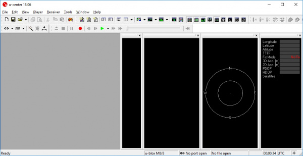
U-center from ublox is a free software tool for configuring ublox GPS receivers under Windows. The software can be obtained here. To follow along with this tutorial please download and install u-center. Once completed open it.

U-center default look

U-center is a dense program with many interface elements. It can be overwhelming at first but over time it will become easier to use. For all its GUI weaknesses it is very powerful for configuring the ublox line of modules include the NEO-M8P-2.

For this tutorial we’ll assume you have the SparkFun GPS-RTK but u-center can be used with any ublox based product. Start by attaching a microB cable to the GPS-RTK board.

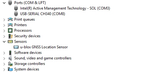
NEO-M8 module seen as location sensor in device manager

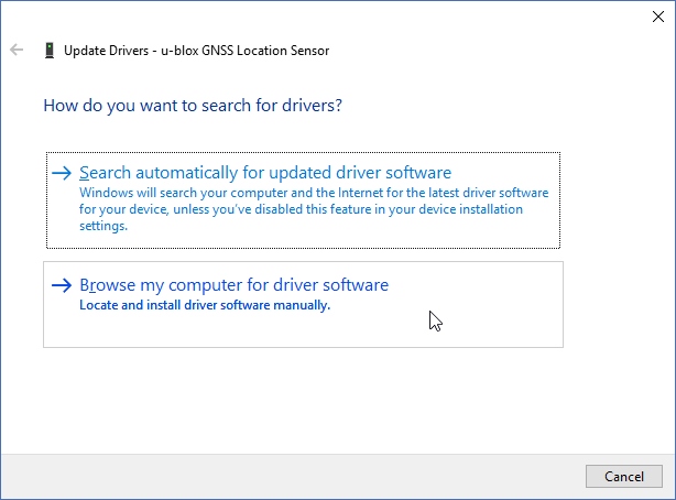
Now open Windows Device Manager. The NEO-M8 series has an annoying feature where the module comes up as a Windows Sensor rather than a serial device. If your ublox receiver does not appear under COM ports then right click on the u-blox GNSS Location Sensor and then Update Driver.

Click browse my computer

Next click on Browse my computer for driver software.

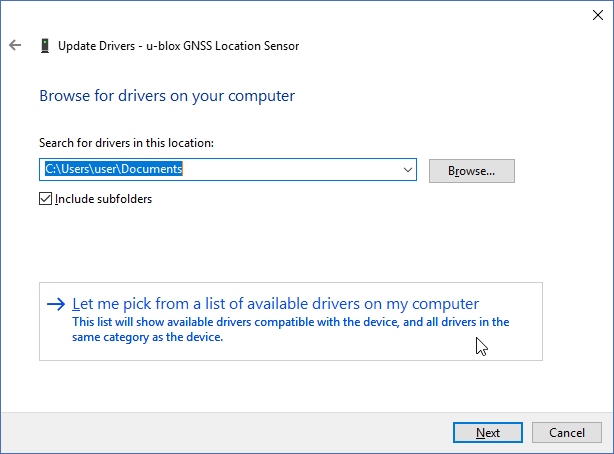
Let me pick button

Then “Let me pick”…

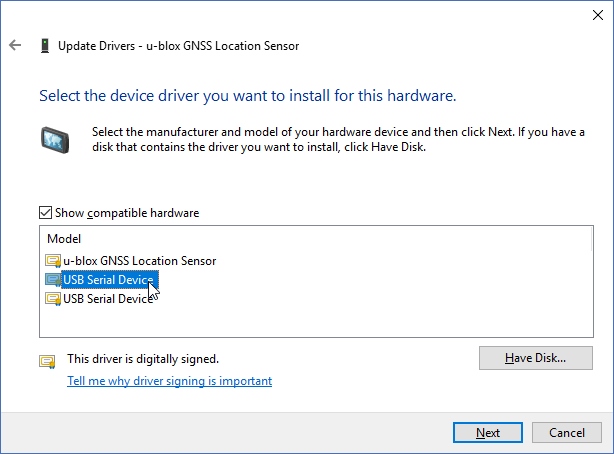
Select USB device

Select the first USB serial device.

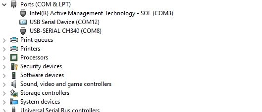
NEO-M8P showing up as COM port

The SparkFun GPS-RTK board should now enumerate as a USB serial com port. In the above list the GPS-RTK board is COM12.

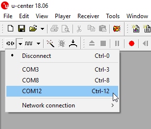
List of com ports in u-center

Return to u-center and drop down the port list. Select the COM port that is your RTK board. Congrats! You can now use u-center.

Let’s go over a few windows you’ll likely use:

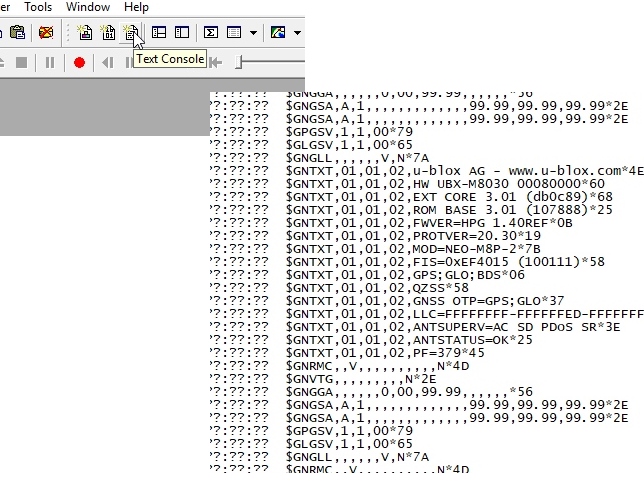
Text Console

u-center text console

Text console will show you the raw NMEA sentences. This is handy for quickly inspecting the visible ASCII coming from the module over USB.

Configure

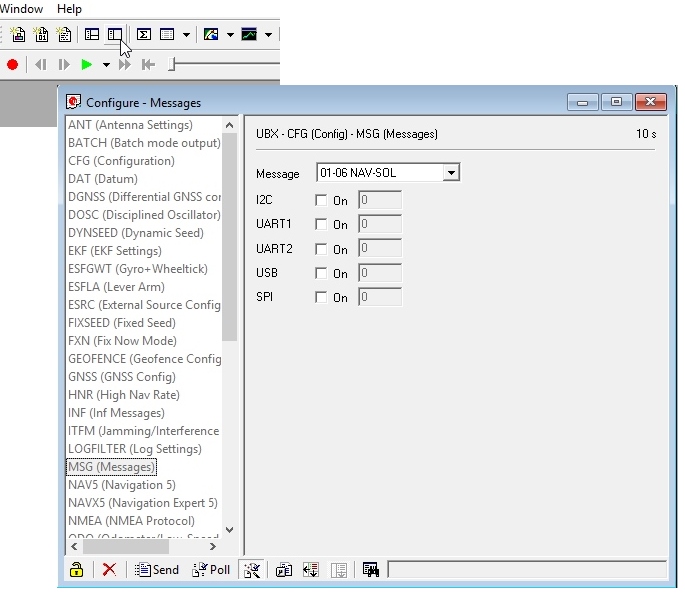
Configuration button and msg window

The configuration button opens the most powerful window. From this window you can inspect and configure new settings. It’s not obvious but when you click on a setting such as ‘MSG’ u-center will poll the module for its current state. The ‘10s’ in the corner indicates how old the displayed information is. In this case it’s been 10 seconds since this setting was last queried. Click on the ‘Poll’ button to update the information. Go ahead and select the F0-00 NMEA GxGGA message. As you click the dropdown the software will poll the current settings. It’s a bit disorienting at first but gets better over time.

The MSG configuration is very powerful. It allows you to enable or disable various NMEA sentences as well as binary protocols such as NAV-PVT (checkout the full protocol datasheet)). Once a sentence is selected, such as GxGGA, the check boxes will be populated. If you want to disable the GxGGA sentence for the SPI interface uncheck the SPI checkbox then click ‘Send’. Congrats! The GxGGA sentence is no longer presented on the SPI interface. This raises an important fact:

Note: The NEO-M8 series has 4 interfaces: USB(serial), I2C, SPI, and UART. All interfaces can access information simultaneously. This means you can inspect configuration settings over the USB serial port while your Arduino makes setting changes over the I2C port. You can read NMEA sentences over the I2C port or send RTCM data into the module over SPI. It’s all highly configurable.

What is the USB port on the NEO-M8P? It’s like any other USB to serial device. It will enumerate on your computer as a COM port and acts as such. It is independent and separate from the UART port that is a dedicated TTL serial port.

If something is not accessible through u-center it probably means that feature or setting is not compatible with the currently attached device. For example, in the image above the UART2 box is grayed out. The NEO-M8P does not have a second UART so you can’t address it.

Ports

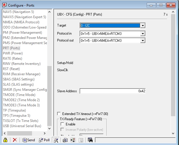
u-center ports menu

The Ports (PRT) sub-menu under Configuration is very helpful. You can do things like change the baud rate, I2C address, and protocols. Depending on your application you may want to enable or disable entire interface protocols. For example, if you want to enable NMEA sentences for the SPI interface you would do it here. Fortunately the factory default for the NEO-M8P is good for I2C and UART1 for RTK purposes (input of RTCM3 is enabled for both ports).

This is also the menu that allows you to change the I2C address of your GPS-RTK. Because we are big fans of Qwiic we’ll be using the GPS-RTK on the I2C bus. If we had another device on the bus that uses address 0x42 this menu will allow us to change the address of the GPS-RTK.

Poke around the various config menus. If you get your module into an unknown state you can unplug and replug to reset the settings.

Messages

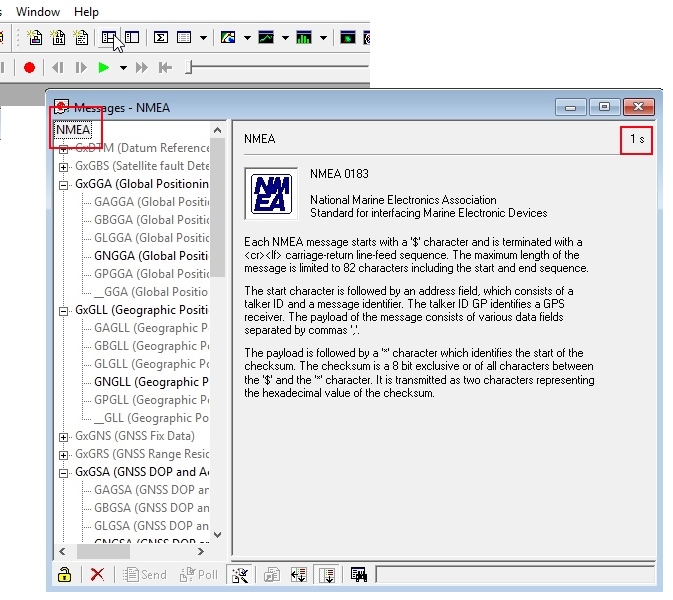
MSG window

The messages window will allow you to view the various sentences reported by the module. It’s not obvious but if you double click on ‘NMEA’ the tree of messages will fold away. Similarly, if you double click on ‘UBX’ it will expand showing the various UBX sentences. By default many of these are not enabled but we’ll get to that.

Resources and Going Further

Once you’ve mastered U-Center you’re ready to begin configuring your Ublox module!

Building an Autonomous Vehicle: The Batmobile

Documenting a six-month project to race autonomous Power Wheels at the SparkFun Autonomous Vehicle Competition (AVC) in 2016.
New!

GPS-RTK Hookup Guide

Find out where you are! Use this easy hook-up guide to get up and running with the SparkFun high precision GPS-RTK board.

learn.sparkfun.com | CC BY-SA 3.0 | SparkFun Electronics | Niwot, Colorado
GPS-RTK Hookup Guide

$
0
0

GPS-RTK Hookup Guide a learn.sparkfun.com tutorial

Available online at: http://sfe.io/t814

Introduction

Ublox GPS-RTK (Qwiic) - NEO-M8P-2

Ublox GPS-RTK (Qwiic) - NEO-M8P-2

SPX-14980
$149.95

The NEO-M8P-2 module is the top-of-the-line module for high accuracy GNSS and GPS location solutions including RTK. The NEO-M8P-2 is unique in that it is capable of both rover and base station operations. The ‘-2’ designation means this module has survey-in mode allowing the module to become a base station and produce RTCM 3.x correction data. From here on we will refer to the module as NEO-M8P but it should not be confused with the NEO-M8P-0 module (which is not able to produce RTCM data).

Suggested Reading

I2C

An introduction to I2C, one of the main embedded communications protocols in use today.

Serial Basic Hookup Guide

Get connected quickly with this Serial to USB adapter.
New!

What is GPS RTK?

Learn about the latest generation of GPS and GNSS receivers to get 2.5cm positional accuracy!
New!

Getting Started with U-Center

Learn the tips and tricks to use the u-blox software to configure your GPS receiver.

Before getting started be sure to checkout our What is GPS RTK? tutorial and if you want to pre-read a bit have a look at our Getting Started with U-Center.

Hardware Overview

Communication Ports

SparkFun GPS RTK Evaluation Board

The NEO-M8P-2 in unique in that it has four communication ports which are all active simultaneously. You can read NMEA data over I2C while you send configuration commands over the UART and vice/versa. The only limit is that the SPI pins are mapped onto the I2C and UART pins so it’s either SPI or I2C+UART. The USB port is available at all times.

USB

GPS RTK USB Port

The microB connector makes it easy to connect the NEO-M8P to u-center for configuration and quick viewing of NMEA sentences. It is also possible to connect a Raspberry Pi or other SBC over USB. The NEO-M8P enumerates as a serial COM port and is a seperate serial port from the UART interface. See Getting Started with U-Center for more information about getting the USB port to be a serial comm port.

A 3.3V regulator is provided to regulate the 5V USB down to 3.3V the module requires. External 5V can be applied or a direct feed of 3.3V can be provided. Note that if you’re provide the board with 3.3V directly it should be a clean supply with minimal noise (less than 50mV VPP ripple is ideal for precision locating).

I2C (a.k.a DDC)

I2C ports on GPS RTK Evaluation Board

The u-blox NEO-M8P has a “DDC” port which is really just an I2C port (without all the fuss of trademark issues). All features are accessible over the I2C ports including reading NMEA sentences, sending UBX configuration strings, piping RTCM data into the module, etc. We’ve written a handful of sketches and an Arduino library to aid in using the NEO-M8P over I2C a snap.

UART/Serial

UART on the NEO-M8P

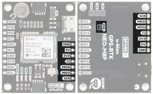
The classic serial pins are available on the NEO-M8P but are shared with the SPI pins. Because USB covers most serial needs we didn’t label the UART pins explicitly. By default the UART pins are enabled. Be sure the DSEL jumper on the rear of the board is open.

  • MISO = TX out from NEO-M8P
  • MOSI = RX into NEO-M8P

SPI

SPI ports on the SparkFun NEO-M8P

The NEO-M8P can also be configured for SPI communication. By default the SPI port is disable. To enable SPI close the DSEL jumper on the rear of the board. Closing this jumper will disable the UART and I2C interfaces.

Control Pins

Control pins on the NEO-M8P-2

This pins are used for various extra control of the NEO-M8P:

  • FENCE : Geofence output pin. Configured with U-Center. Will go high or low when a geofence is setup. Useful for triggering alarms and actions when the module exits a programmed perimeter.
  • RTK: RTK output pin. Remains high when module is normal GPS mode. Begins blinking when RTCM corrections are received and module enters RTK float mode. Goes low when module enters RTK fixed mode and begins outputting cm-level accurate locations.
  • PPS: Pulse-per-second output pin. Begins blinking at 1Hz when module gets basic GPS/GNSS position lock.
  • RST: Reset input pin. Pull this line low to reset the module.
  • SAFE: Safeboot input pin. This is required for firmware updates to the module and generally should not be used or connected.
  • INT: Interrupt input/output pin. Can be configured using U-Center to bring the module out of deep sleep or to output an interrupt for various module states.

Antenna

Antenna connector on GPS-RTK

The NEO-M8P requires a good quality GPS or GNSS (preferred) antenna. A U.FL connector is provided. Note: U.FL connectors are rated for only a few mating cycles (about 30) so we recommend you set it and forget it. A U.FL to SMA cable threaded through the mounting hole provides a robust connection that is also easy to disconnect at the SMA connection if needed. Low-cost magnetic GPS/GNSS antennas can be used (checkout the ublox white paper) but a 4” / 10cm metal disc is required to be placed under the antenna as a ground plane.

LEDs

LEDs on the SparkFun NEO-M8P eval board

The power (PWR) LED will illuminate when 3.3V is activated either over USB or via the Qwiic bus.

The pulse per second (PPS) LED will illuminate with each successful update once a position lock has been achieved.

The RTK LED will be illuminated constantly upon power up. Once RTCM data has been successfully received it will begin to blink. This is a good way to see if the NEO-M8P is getting RTCM from various sources.

The FENCE LED can be configured to turn on/off for geofencing applications.

Jumpers

Jumnpers on GPS RTK

Closing DSEL enables the SPI interface and disables the UART and I2C interfaces. USB will still function.

Cutting the I2C jumper will remove the 2.2k Ohm jumpers from the I2C bus. If you have many devices on your I2C bus you may want to remove these jumpers. Not sure how to cut a jumper? Read here!

Jumpers JP1, JP2, JP3, are provided on the rear of the board to allow isolation of the various status LEDs.

Backup Battery

alt text

The MS621FE rechargeable battery maintains the battery backed RAM (BBR) on the NEO-M8P. This allows for much faster position locks. The BBR is also used for module configuration retention. The battery is automatically trickle charged when power is applied and should maintain settings and GNSS orbit data for up to two weeks without power.

Connecting an Antenna

UFL cable threaded through standoff hole

U.FL connectors are very good but they are a designed to be implemented inside a small embedded application like a laptop. Exposing a U.FL connector to the wild risks it getting damaged. To prevent damaging the U.FL connection we recommend threading the U.FL cable through the stand-off hole, then attach the U.FL connectors. This will provide a great stress relief for the antenna connection. Now attach your SMA antenna of choice.

Be careful: U.FL connectors are easily damaged. Make sure the connectors are aligned, flush face to face (not at an angle), then press down using a rigid blunt edge such as the edge of a PCB or point of a small flat head screwdriver.

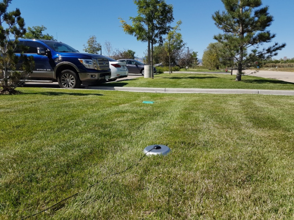
GPS antenna in grass

If you’re indoors you must run a SMA extension cable long enough to locate the antenna where it has a clear view of the sky. That means no trees, buildings, walls, vehicles, or concrete metally things between the antenna and the sky. Be sure to mount the antenna on a 4”/10cm metal ground plate to increase reception.

Connecting the GPS-RTK to a Correction Source

Before you go out into the field it’s good to understand how to get RTCM data and how to pipe it to the GPS-RTK. For this example we will show how to get correction data from the UNAVCO network, pull that data in using RTKLIB, and pipe it down over serial to the GPS-RTK.

You will need:

Software:

  • Credentials with a free RTCM provider such as UNAVCO
  • U-Center
  • Download and unzip RTKLIB. We will be using 2.4.2.

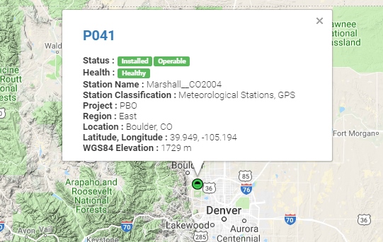
UNAVCO has fairly good coverage in the USA. Using their interactive map find a station that is near your location. It’s ok if it is more than 10km (6 miles) away, we’re just practicing.

UNAVCO site near SparkFun

Site P041 is pretty close to SparkFun HQ. We’ll be using it. To access UNAVCO data feeds you will need to send an email to rtgps@unavco.org to request credentials. Let UNAVCO know if you are affiliated with any business, school or organization and if you are using the account for personal use. Access to UNAVCO is free; I believe they need this information for reporting on their grant funding.

Once you have your UNAVCO credentials open RTKLIB (in Windows run rtklaunch.exe).

RTKLIB Launch window

This small window allows you to launch the various RTK programs. For this tutorial we’ll be using RTKNAVI, the second button from the right.

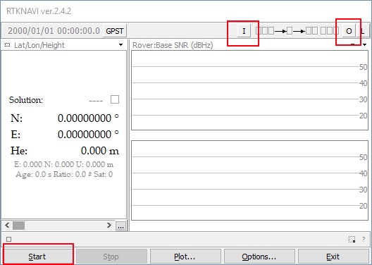
RTKLIB Navigation Screen

RTKNAVI allows you to connect to RTCM feeds from various providers, including UNAVCO. Click on the small “I” button.

RTKNAVI Input Streams

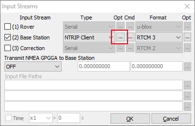
From the input stream window click the check box next to ‘Base Station’, select NTRIP Client from the dropdown, and the RTCM 3 format. Next click on the small three dots under Opt - this will open the NTRIP client configuration options.

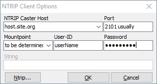
RTKLIB Navigaion Client Options

Enter the UNAVCO domain, port, and credentials that you were issued. Next click on the Ntrip button. This will launch the Ntrip browser so that we can located the P041 station.

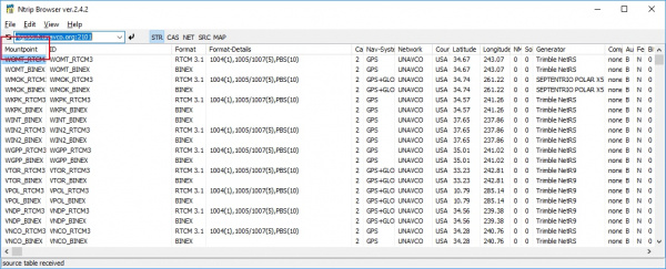
NTRIP Browsing of streams

Ntrip browser allows you to connect to different providers and view what streams are available. I wish it was as simple as being able to search for ALL the RTCM streams near a given location but no option currently exists. Instead, we must connect to each provider and see what locations they provide, and what type of correction streams are produced by a given location. Remember, the NEO-M8P only works with RTCM 3.x.

This list is quite large and we’re looking for P041 so click on the Mountpoint column header to sort the list alphabetically.

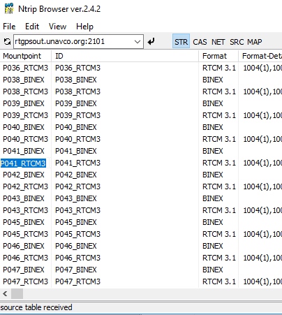
Copying a mountpoint in NTRIP

Once we have P041 located, we want the RTCM feed so copy and paste that mountpoint back into RTKNAVI into the ‘Mountpoint’ box. Once you’ve entered all your credentials and mountpoint click OK to close the NTRIP Client Options window. You can also close the Ntrip browser.

The input stream should be configured so click OK in the Input Stream window to complete configuration. Click ‘Start’ from the RTKNAVI window to test the connection to the UNAVCO server.

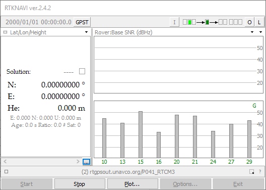
Streaming RTCM in RTKNAVI

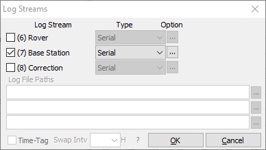
Success! We are receiving a stream. Now we need to output this data. Click the L button for ‘Logging’.

Log RTCM stream to serial

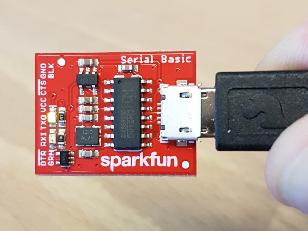
We want to log the Base Station stream to the serial port so now is a good time to connect your Serial Basic or FTDI board. Once the board enumerates you should have a new serial port. If you run into problems or need drivers checkout the Serial Basic Hookup Guide.

Click the ‘…’ button to configure your serial port. Note that you’ll need to select the same baud rate as your GPS-RTK module is configured for. By default the NEO-M8P communicates at 9600bps 8-N-1 so use this setting. Once you have things configured properly the TX LED on the Serial basic should blink once per second indicating the UNAVCO server is pushing data all the way down to the TX pin on the Serial Basic.

Blinking TX LED on Serial Basic

The RTCM pipe is complete, now we need to connect the “last inch” to the NEO-M8P.

SparkFun GPS-RTK with USB and antenna

Time to power up up the GPS-RTK board. Attach a microB cable to the GPS-RTK board. The power LED should illuminate. Open the U-Center software from Ublox. Be sure to read Getting Started with U-Center if you haven’t already. Thankfully, the NEO-M8P’s default configuration allows it to receive RTCM correction data without any further changes. All you need to do is feed the NEO-M8P with serial data and it will begin calculating the high precision location solution.

Select the correct COM port and begin viewing the NMEA data. You should have a position lock very quickly. Once the PPS LED begins to blink you are ready to start piping RTCM data to the GPS-RTK board.

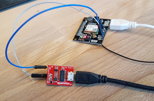
Serial basic connected to NEO-M8P

The Serial Basic board should still be blinking once a second with RTCM data from the UNAVCO server. Using two jumper wires connect GND on the Serial Basic to GND on the GPS-RTK. Next, connect TXO to the MOSI pin on the GPS-RTK. The MOSI pin is the RX UART pin by default (when DSEL jumper is open). Jumper wires without solder are obviously a precarious setup but we’re just testing things out. Arrange things so the connection is semi-permanent. Within a few seconds you should see the RTK LED begin to blink. Congratulations! Your GPS module has entered RTK float mode. When the RTK LED turns off completely then the module has solved the carrier ambiguities and entered RTK fixed mode and is outputting centimeter level positions!

Once you have the GPS-RTK receiving RTCM correction data successfully you can begin plan how to obtain and deliver the RTCM data to the GPS-RTK. The options are vast and varied:

  • It is possible to pull get Ntrip data on an Android app and pipe it over a Bluetooth serial device like the Bluetooth Mate Silver. It’s trivial to connect a Bluetooth serial device to the GPS-RTK serial pins.
  • If you need maximum portability a radio link can be the lowest power, smallest footprint. SparkFun offers a variety of LoRa radios and antennas. With the help of a microcontroller these radios can pipe data from the LoRa backhaul over an Qwiic I2C port, serial, even SPI.
  • If your end application already requires an internet connection such as GSM or LTE-CAT then a microcontroller could feasibly connect to an Ntrip server over the internet then pipe the RTCM data over a serial or an I2C connection on the GPS-RTK.

GPS-RTK Arduino Library

The GPS-RTK Arduino library enables the reading of NMEA data over I2C as well as sending binary UBX configuration commands over I2C. This is helpful for configuring advanced modules like the NEO-M8P-2.

The SparkFun Ublox Arduino library can be downloaded with the Arduino library manager by searching ‘SparkFun Ublox’ or you can grab the zip here:

SparkFun Ublox Arduino Library (ZIP)

Once you have the library installed checkout the various examples.

  • Example1: Read NMEA sentences over I2C using Ublox module SAM-M8Q, NEO-M8P, etc
  • Example2: Parse NMEA sentences using MicroNMEA library. This example also demonstrates how to overwrite the processNMEA function so that you can direct the incoming NMEA characters from the Ublox module to any library, display, radio, etc that you prefer.
  • Example3: Send UBX binary commands to enable RTCM sentences on Ublox NEO-M8P-2 module. This example is one of the steps required to setup the NEO-M8P as a base station. For more information have a look at the Ublox manual for setting up an RTK link.
  • Example4: This example extends example 3 sending all the commands to the NEO-M8P-2 to have it operate as a base. Additionally the processRTCM function is exposed. This allows the user to overwrite the function to direct the RTCM bytes to whatever connection the user would like (radio, serial, etc).

NMEA and RTK

Can I really use NMEA with a high precision GPS receiver?

Yes! Except that NMEA sentences are right on the edge of enough precision. NMEA sentences look something like this

$GNGGA,012911.00,4003.19080,N,10416.95542,W,1,12,0.75,1647.1,M,-21.3,M,,*4F

NMEA outputs coordinates in the ddmm.mmmmm format. So what is the weight of the least significant digit? Said differently, what is the impact of one digit change?

104 16.95542

vs

104 16.95543

If we know 1 degree of latitude is 111.3km at the equator we can glean the change of a fraction of a minute:

  • 1 degree = 60 minutes
  • 1 minute = 1 degree/60 = 111.32km / 60 = 1.855km
  • 1 minute = 1855m
  • 0.1min = 185.5m
  • 0.01min = 18.55m
  • 0.001min = 1.855m
  • 0.0001min = .1855m = 185.5mm
  • 0.00001min = 0.0185m = 18.55mm = 1.855cm

Using NMEA sentence the NEO-M8P will only be able to communicate a change of ~1.5cm location change for each digit in the 5th position. This is pretty close to the 2.5cm accuracy of the module. If you want additional precision you should consider using the UBX protocol which can output up to 8 digits of precision in dd.dddddddd format which will get you down to 1.11mm of precision.

Resources and Going Further

Have fun with your new found super power: sub decimeter grade GPS!

Building an Autonomous Vehicle: The Batmobile

Documenting a six-month project to race autonomous Power Wheels at the SparkFun Autonomous Vehicle Competition (AVC) in 2016.
New!

Getting Started with U-Center

Learn the tips and tricks to use the u-blox software to configure your GPS receiver.

learn.sparkfun.com | CC BY-SA 3.0 | SparkFun Electronics | Niwot, Colorado
What is GPS RTK?

$
0
0

What is GPS RTK? a learn.sparkfun.com tutorial

Available online at: http://sfe.io/t813

Real Time Kinematics

RTK is short for real time kinematics. A GPS receiver capable of RTK takes in the normal signals from the Global Navigation Satellite Systems along with a correction stream to achieve 2.5cm positional accuracy. GNSS includes satellites from GPS (USA), Glonass (Russia), Beidou (China), and Galileo (Europe). On top of these signals an RTK receiver takes in an RTCM correction stream and then calculates your location with 2.5cm accuracy in real time. The rate varies between receivers but most will output a solution at least once per second; some receivers can output this higher precision solution up to 4 times a second. RTK capable GPS receivers used to be thousands of dollars and were limited to professional surveyors and government groups. Thanks to science, math, and economics RTK receivers are now less than $200.

alt text

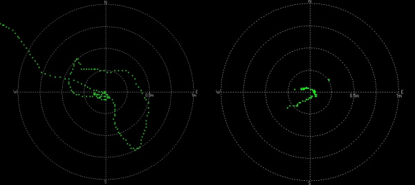
On the left we have a extremely high quality GPS receiver (NEO-M8P-2) with no correction data. The position wanders greatly over 1.5 meters and beyond. On the right the same receiver, with the same antenna, with RTCM correction data brings the position under 25cm with tight groupings under 10cm.

Did you say 2.5 cm? Zomg how do I get 2.5 cm accuracy!?

You’ll need a GPS receiver capable of receiving and incorporating the RTCM correction data into its location solution. You’ll also need a source of RTCM correction data. This usually comes from an internet connection or a long distance radio capable of approximately 500 bytes per second. LoRa and LTE-CAT M1 are superb choices for this backhaul.

Once it’s all setup and working the rover GPS module will output normal NMEA sentences but with really accurate lat and long. To be clear, it’s not 2.5cm precision; it’s 2.5cm (1 inch) accuracy. The precision is 0.1mm!

2.5cm accuracy is possible with lower cost receivers (such as the NEO-M8T) by capturing raw streams from the GPS satellites and then post processing the logs with an open source program called RTKLIB. This is handy for applications like aerial photography and agricultural inspection were alignment is important after the fact. It’s also possible to tether a lower cost receiver (such as the NEO-M8T) to a laptop and run RTKLIB in unison and achieve real time solutions but this is a rather large, power hungry setup that is not ideal for embedded mobile applications. In these tutorials we will be focusing on real time (RTK) capable receivers.

What is RTCM?

RTCM is an acronym for Radio Technical Commission for Maritime. This governmental body came up with a way to communicate positions for boats and other vessels many decades ago. Technically RTCM is just a protocol. We, however, will be using the term RTCM to mean the bytes of correction data related to GPS timing anomalies.

alt text

From Review of GNSS Formats for Real-Time Positioning and Geo++

The contents of RTCM frames can be decoded but you, the user, rarely need to. Instead you simply pass the bytes to the GPS receiver and it will parse the correction data.

There are a few different types of messages but the ones we care about are numbers 1005, 1077, 1087, and 1230. Each message type has a different length but as a rule of thumb it’s a couple hundred bytes every second. Each RTCM message contains details about the GPS/GNSS network, and perturbations in the ionosphere and troposphere.

Remember, the GPS satellites are very far away; about 20km or 12,000 miles away. A lot can happen to the signal from the GPS satellites to you across that distance. Geomagnetic storms cause slight timing delays increasing the location error. Earth’s gravitational field is not uniform so relativistic effects can add inaccuracies. If we know the second to second issues within our local vicinity an RTCM capable receiver can correct the location solution with great precision.

Note: There are a few different versions of RTCM. The most popular versions are v2 and v3. Because v3 is considered an ‘open’ standard, and because it incorporates messages helpful for RTK, more companies have implemented version 3 making it the more common standard.

Where do I get RTCM corrections?

If you’re lucky there’s a station within 10km (6 miles) of you that is broadcasting RTCM 3.x data over the internet.

alt text

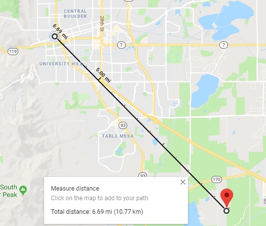
We located one a little more than 10 km from SparkFun HQ that works really well.

Here’s a list of stations we’ve found. If there are more you know of please let us know:

Many of the stations that broadcast real time RTCM correction data require registration. It’s a wild hodge-podge of scientific and non-profit civil organizations across the globe. It feels very internet-circa-1995. If anyone has a more straightforward way of discovering and connecting to RTCM providers, please let us know in the comments section.

We recommend using RTKLIB to subscribe to the feed and output the stream over a serial port to a GPS RTK capable module. For the best accuracy your GPS receiver will need to be within 10km (6 miles) of the broadcast station. If you are greater than 10km the NEO-M8P can still create location fixed but the accuracy is degraded and the receiver will output a “WARNING: DGNSS baseline big: 10km”.

Another option for RTCM data is to create your own station! You’ll need a GPS module capable of generating RTCM correction data, a sensitive antenna, and computer or SBC to take the RTCM data and serve it over the internet. You’ll need a clear view of the sky and probably a very long SMA extension cable to get from your desk to the antenna. There are some very expensive receivers capable of base station RTCM. Luckily, there is also the NEO-M8P-2 module that is lower cost and just as capable. We will be focusing on how to use the NEO-M8P-2 in the following tutorials.

How do I get the RTCM messages to the GPS receiver?

It depends on your end application. If you need maximum portability then the best solution is a radio link between base station you’ve created and mobile GPS RTK receiver. SparkFun offers a variety of LoRa radios and antennas to enable this backhaul.

If your end application already requires an internet connection such as GSM or LTE-CAT then a serial connection to the GPS-RTK receiver may be the easiest way to go.

If your application has a cell phone nearby then a third option is to create a serial bridge from a cell phone to a serial Bluetooth device like the Bluetooth Mate Silver that then connects to the serial port on the GPS-RTK. There are a few Ntrip compatible mobile apps. We’ve been pleased with Lefebure for Android.

Resources and Going Further

We hope this tutorial helps you understand a bit more about GPS RTK. This is just the beginning!

New!

GPS-RTK Hookup Guide

Find out where you are! Use this easy hook-up guide to get up and running with the SparkFun high precision GPS-RTK board.
New!

Getting Started with U-Center

Learn the tips and tricks to use the u-blox software to configure your GPS receiver.

learn.sparkfun.com | CC BY-SA 3.0 | SparkFun Electronics | Niwot, Colorado
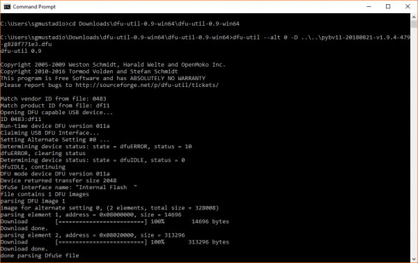
How to Run a Raspberry Pi Program on Startup

$
0
0

How to Run a Raspberry Pi Program on Startup a learn.sparkfun.com tutorial

Available online at: http://sfe.io/t812

Introduction

The Raspberry Pi is a great single board computer, but like most computers, its functions rely mostly on human input. That means whenever you start up (or boot) your computer, it waits for your input to run programs. That’s great, but how do we get our programs to run automatically whenever the computer boots?

Linux is a fairly complex operating system, and as such, there are often multiple ways to perform any one action. To get a program to run on boot, we will cover several ways. To show some example programs, we will blink an LED and turn the Raspberry Pi into a clock.

Running a Python program on boot with a Raspberry Pi

While using the Raspberry Pi as a clock might seem like overkill, feel free to substitute your own program or script instead. You are also welcome to use the example code as the basis for your own dashboard (e.g. show the local forecast when you wake up, your personal server uptime, number of days left until your favorite show, etc.) or electronics project.

Notice: This tutorial was written with Raspbian version "June 2018" and Python version 3.5.3. Other versions may affect how some of the steps in this guide are performed.

Before adding your program to any startup script, it’s extremely important that you test it first on its own! Run it with just the python command to make sure there are no problems with your program. It’s much harder to track down bugs in your code when it runs as part of the boot process.

The three methods covered in this tutorial are:

  • rc.local - Likely the easiest and simplest way to get your program to run on boot. The downside is that tasks started with rc.local happen before the X windows system starts, which means you will not have access to graphical user interface (GUI) elements.
  • autostart - Used to automatically run your programs once LXDE (graphical desktop environment used by Raspbian) starts. It’s slightly more complicated than rc.local, but it lets you run programs that require graphical elements.
  • systemd - The new and popular way to automatically start programs in Linux. It is definitely the most complicated of the three, but it allows you to run before LXDE starts, wait until you have access to other processes (e.g. networking, graphical desktop), or simply restart your program over and over again until it works. As such, it is a robust way to create and manage services that run in the background.

Required Materials

At a bare minimum, you will need a Raspberry Pi, SD card, and power supply for this tutorial. If you plan to make a dashboard (or clock, as given by the example code in the next section), you will need a monitor and keyboard for your Pi. If you would like a full desktop setup, we recommend the following:

Suggested Reading

If you aren’t familiar with the following concepts, we recommend checking out these tutorials before continuing:

Raspberry Pi 3 Starter Kit Hookup Guide

Guide for getting going with the Raspberry Pi 3 Model B and Raspberry Pi 3 Model B+ starter kit.

Getting Started with the Raspberry Pi Zero Wireless

Learn how to setup, configure and use the smallest Raspberry Pi yet, the Raspberry Pi Zero - Wireless.

Python Programming Tutorial: Getting Started with the Raspberry Pi

This guide will show you how to write programs on your Raspberry Pi using Python to control hardware.

Python GUI Guide: Introduction to Tkinter

Tkinter is the standard graphical user interface package that comes with Python. This tutorial will show you how to create basic windowed applications as well as complete full-screen dashboard examples complete with live graph updates from matplotlib.
Please note: If you have trouble seeing any of the images throughout this tutorial, feel free to click on it to get a better look!
Python Logo

Example Code

In the rest of the tutorial, we will show starting Python programs on boot with two examples: blink.py and clock.py. Note that any program (compiled, script, etc.) can be used, but choosing the right method for starting your script is important. For example, using rc.local, while easy, does not give you access to the X server (the thing that gives you a GUI desktop). So, rc.local for a GUI program is not the right tool, and you should try another method.

The Linux boot sequence is a fairly complex sequence of events, which can easily be its own article for another time. If you would like to learn more about it, check out these links:

blink.py

While external connections to hardware is not necessary to show how to run a program on boot, it can be a useful way to show that something is running in the background, even if you do not see anything on the screen. Connect an LED and a 330 Ω resistor between GPIO12 and GND on the Raspberry Pi.

LED connected to Raspberry Pi Fritzing diagram

On your Raspberry Pi, open a terminal, and make sure you are in your home directory:

language:shell
cd /home/pi

Open a new document named blink.py

language:shell
nano blink.py

Copy in the following code:

language:python
import time
import RPi.GPIO as GPIO

# Pin definitions
led_pin = 12

# Use "GPIO" pin numbering
GPIO.setmode(GPIO.BCM)

# Set LED pin as output
GPIO.setup(led_pin, GPIO.OUT)

# Blink forever
try:
    while True:
        GPIO.output(led_pin, GPIO.HIGH) # Turn LED on
        time.sleep(1)                   # Delay for 1 second
        GPIO.output(led_pin, GPIO.LOW)  # Turn LED off
        time.sleep(1)                   # Delay for 1 second

# When you press ctrl+c, nicely release GPIO resources
finally:
    GPIO.cleanup()

Save it with ctrl + x, press y when asked to save, and press enter. Run the program with the following:

language:shell
python blink.py

You should see the LED begin to blink on and off. Press ctrl + c to stop the program.

Blinking an LED with Python on a Raspberry Pi

clock.py

The next example that we’ll use is slightly more complicated, as it relies on a GUI made with the Tkinter package. We’ll use this program when we want to demonstrate how to start a program on boot that requires the X windows system (for example, you want to make a graphical dashboard that is displayed on boot).

On your Raspberry Pi (in your home directory, /home/pi), open a new document with the name clock.py:

language:shell
nano clock.py

Copy in the following code:

language:python
import tkinter as tk
import tkinter.font as tkFont
import time

###############################################################################
# Parameters and global variables

# Default font size
font_size = -24

# Declare global variables
root = None
dfont = None
frame = None
dtime = None

# Global variable to remember if we are fullscreen or windowed
fullscreen = False

###############################################################################
# Functions

# Toggle fullscreen
def toggle_fullscreen(event=None):

    global root
    global fullscreen

    # Toggle between fullscreen and windowed modes
    fullscreen = not fullscreen
    root.attributes('-fullscreen', fullscreen)
    resize()

# Return to windowed mode
def end_fullscreen(event=None):

    global root
    global fullscreen

    # Turn off fullscreen mode
    fullscreen = False
    root.attributes('-fullscreen', False)
    resize()

# Automatically resize font size based on window size
def resize(event=None):

    global time_dfont
    global button_dfont
    global frame

    # Resize font based on frame height (minimum size of 12)
    # Use negative number for "pixels" instead of "points"
    new_size = -max(12, int((frame.winfo_height() / 2)))
    time_dfont.configure(size=new_size)
    new_size = -max(12, int((frame.winfo_height() / 30)))
    button_dfont.configure(size=new_size)


# Read values from the sensors at regular intervals
def update():

    global root
    global dtime

    # Get local time
    local_time = time.localtime()

    # Convert time to 12 hour clock
    hours = local_time.tm_hour
    if hours > 12:
        hours -= 12

    # Add leading 0s
    shours = str(hours)
    smin = str(local_time.tm_min)
    if hours < 10:
        shours = '0' + shours
    if local_time.tm_min < 10:
        smin = '0' + smin

    # Construct string out of time
    dtime.set(shours + ':' + smin)

    # Schedule the poll() function for another 500 ms from now
    root.after(500, update)

###############################################################################
# Main script

# Create the main window
root = tk.Tk()
root.title("My Clock")

# Create the main container
frame = tk.Frame(root, bg='black')

# Lay out the main container (expand to fit window)
frame.pack(fill=tk.BOTH, expand=1)

# Variables for holding temperature and light data
dtime = tk.StringVar()

# Create dynamic font for text
time_dfont = tkFont.Font(family='Courier New', size=font_size)
button_dfont = tkFont.Font(size=font_size)

# Create widgets
label_time = tk.Label(  frame, 
                        textvariable=dtime, 
                        font=time_dfont, 
                        fg='red', 
                        bg='black')
button_quit = tk.Button(frame, 
                        text="Quit", 
                        font=button_dfont, 
                        command=root.destroy,
                        borderwidth=0,
                        highlightthickness=0, 
                        fg='gray10',
                        bg='black')

# Lay out widgets in a grid in the frame
label_time.grid(row=0, column=0, padx=20, pady=20)
button_quit.grid(row=1, column=0, padx=5, pady=5, sticky=tk.E)

# Make it so that the grid cells expand out to fill window
frame.rowconfigure(0, weight=10)
frame.rowconfigure(1, weight=1)
frame.columnconfigure(0, weight=1)

# Bind F11 to toggle fullscreen and ESC to end fullscreen
root.bind('<F11>', toggle_fullscreen)
root.bind('<Escape>', end_fullscreen)

# Have the resize() function be called every time the window is resized
root.bind('<Configure>', resize)

# Schedule the poll() function to be called periodically
root.after(20, update)

# Start in fullscreen mode and run
toggle_fullscreen()
root.mainloop()

Save it with ctrl + x, press y when asked to save, and press enter. Run the program with the following:

language:shell
python clock.py

Your entire screen should be taken up by a rather large clock!

Running a GUI clock program on a Raspberry Pi

If you are interested in learning more about how this program was made (i.e. creating your own graphical user interface with Tkinter), check out our Python GUI Guide: Introduction to Tkinter.

Method 1: rc.local

Running your program from rc.local is likely the easiest method, but because rc.local is executed before X starts, you will not have access to GUI elements. As a result, it’s recommended that you only use rc.local for starting programs that do not have graphical elements.

As your Linux operating system (OS) boots on your Raspberry Pi, it goes through a series of runlevels, which define the state of the system during startup. Whenever the runlevel changes, various run control (rc) scripts are run, which handle starting and stopping various system services. If you would like to learn more about rc scripts, see this article, but for our purposes, we just need to worry about rc.local.

The rc.local script is executed after all of the normal system services have been started (including networking, if enabled) and just before the system switches to a multiuser runlevel (where you would traditionally get a login prompt). While most Linux distributions do not need an rc.local, it’s usually the easiest way to get a program to run on boot with Raspbian.

Modify rc.local

You will need root-level access to modify rc.local, so do so with sudo:

language:shell
sudo nano /etc/rc.local

Scroll down, and just before the exit 0 line, enter the following:

language:shell
python /home/pi/blink.py &
Note: the ampersand (&) at the end of the line is needed so that your Python script runs in a different process and does not block execution of the boot process. Without it, the rc.local script would wait for your script to end before continuing, and if you have an infinite look (like in our blink.py program), you would never get a login prompt.

Modifying rc.local to run a Python script on boot

Notice that we are calling our script with the absolute file location (/home/pi/blink.py), as calling python blink.py from within rc.local will cause python to look for a local file (i.e. blink.py file located in the same directory as rc.local). We use the absolute file location to make it explicit to Python where our program can be found.

Save and exit with ctrl + x, followed by y when prompted to save, and then enter.

Test it by restarting your Pi with sudo reboot.

Troubleshooting

Nothing Happens

If your script is not running, ensure that your script is called with the absolute directory name (e.g. python /home/pi/blink.py &).

If you cannot access the desktop because your script is preventing Linux from finishing its boot sequence, then you might have to get a terminal over serial. Follow these instructions to get a serial terminal into the Pi.

If you cannot get a serial terminal into your Raspberry Pi, then you will likely need to plug your SD card into another computer (Linux or macOS), navigate to etc/rc.local, and remove the line that calls your Python script.

Debugging

You might notice that you don’t see any errors or output from your script, as rc.local does not log or output any information. To get that, change the python call in your rc.local file to the following:

sudo bash -c 'python /home/pi/blink.py > /home/pi/blink.log 2>&1' &

This creates a new shell with sudo (superuser privileges), runs your script, and redirects the output (stdout) to the blink.log file. 2>&1 Says that errors (stderr) should also be redirected to the same log file. Upon rebooting, any output from your Python script (e.g. print() statements) as well as errors should be saved to blink.log. To view the log, enter the following into a terminal (note that you might need to stop your program first to view the contents of the log file):

language:shell
cat blink.log

Use a Specific Version of Python

As it turns out, rc.local runs before .bashrc, so the command python still refers to Python 2 in our startup script! To explicitly call Python 3, we should change our rc.local command to:

language:shell
sudo bash -c '/usr/bin/python3 /home/pi/blink.py > /home/pi/blink.log 2>&1' &

How to Stop Your Program

You might notice that your program runs great, but there’s no easy way to stop it! The simplest method would be to remove (or comment out) the line you added in rc.local followed by a reboot, but that takes a lot of time.

The quickest way to stop your program is to kill its Linux process. In a terminal, enter the following command:

language:shell
sudo ps -ax | grep python

ps -ax tells Linux to list out all the currently processes. We pipe that list to grep, which allows us to search for keywords. We’re looking for python in this example, but feel free to change it to the name of your program or whatever you are using to run your program. Find the process ID (PID) number to the left of the listed process, and use the kill command to terminate that process:

language:shell
sudo kill <PID>
Heads up! Make sure you type the PID correctly! If you kill the wrong process, you could halt Linux, and you would need to reboot again.

Terminating a process with the kill command

If you are using the blink.py example, you should see the LED cease flashing.

How to Stop Your Program from Running on Boot

If you no longer want your program to run on boot, simply open rc.local with:

language:shell
sudo nano /etc/rc.local

Delete the line that you added to run your program, and save and exit with ctrl + x and y. Reboot your computer, and your program should no longer run after boot.

Another Option

rc.local is a good place to start your program whenever the system boots up (before users can log in or interact with the system). If you would like your program to start whenever a user logs in or opens a new terminal, consider adding a similar line to /home/pi/.bashrc.

Method 2: autostart

If you need access to elements from the X Window System (e.g. you are making a graphical dashboard or game), then you will need to wait for the X server to finish initializing before running your code. One way to accomplish this is to use the autostart system.

Note: Raspbian is based on the LXDE desktop environment. As a result, the location of the autostart script might be different depending on your particular Linux computer and distribution version.

After your desktop environment starts (LXDE-pi, in this case), it runs whatever commands it finds in the profile’s autostart script, which is located at /home/pi/.config/lxsession/LXDE-pi/autostart for our Raspberry Pi. Note that the directory pi might be different if you created a new user for your Raspberry Pi. If no user autostart script is found, Linux will run the global /etc/xdg/lxsession/LXDE-pi/autostart script instead.

In addition to running commands in autostart, Linux will also look for and execute .desktop scripts found in /home/pi/.config/autostart. The easiest way to execute GUI programs on boot is to create one of these .desktop scripts.

Create a .desktop File

You do not need root-level access to modify your profile’s (user’s) autostart and .desktop files. In fact, it is recommended that you do not use sudo, as you may affect the permissions of the file (e.g. the file would be owned by root) and make them unable to be executed by autostart (which has user-level permissions).

Open a terminal, and execute the following commands to create an autostart directory (if one does not already exist) and edit a .desktop file for our clock example:

language:shell
mkdir /home/pi/.config/autostart
nano /home/pi/.config/autostart/clock.dekstop

Copy in the following text into the clock.desktop file. Feel free to change the Name and Exec variables to your particular application.

[Desktop Entry]
Type=Application
Name=Clock
Exec=/usr/bin/python3 /home/pi/clock.py
Note: We are calling python3 explicitly here to prevent any confusion about which Python version to use.

.desktop file for running a Python script on boot

Save and exit with ctrl + x, followed by y when prompted to save, and then enter. Reboot with:

language:shell
sudo reboot

When your Raspberry Pi starts up, make sure to log in to the desktop (if it does not do so automatically). Your script should start running right away!

Troubleshooting

Nothing Happens

If your script does not run as soon as you see the desktop, there could be several issues. First, make sure that you have logged in (autostart does not start until you have logged in). You could also try enabling auto-login in raspi-config. Second, make sure you are using absolute directory names (e.g. /home/pi/clock.py). Third, try following some of the suggestions below to enable stdout and stderr to see what’s going on.

Use a Specific Version of Python

As it turns out, autostart runs before .bashrc, so the command python still refers to Python 2. To explicitly call Python 3, we should change our command in autostart to:

@/usr/bin/python3 /home/pi/clock.py

Debugging

Unfortunately, running a program from autostart makes it difficult to output or log to a file, and lxterminal (the default terminal program in Raspbian) is too simplistic to help us here. To get some kind of logging, we’ll need to use a different terminal program (we’ll use xterm). Open a terminal and enter the following command

language:shell
sudo apt-get install xterm -y

In your .desktop file, change your Exec command to the following:

Exec=xterm -hold -e '/usr/bin/python3 /home/pi/clock.py'

Restart your Raspberry Pi. Now, after you log into your desktop, you should see a new terminal window open followed by your program running. If you stop your program (exiting out of it, pressing ctrl + c in the xterm window, or killing the process as detailed below), the xterm window will stay open, allowing you to read all of the output and error statments from your program.

How to Stop Your Program

If your program is running in the background, there might be no obvious way of halting it. You can always delete your .desktop files and restart, but that might take a while. A better option might be to kill the process associated with your program. In a terminal, enter the following:

language:shell
sudo ps -ax | grep python

ps -ax tells Linux to list out all the currently processes. We send that output to grep, which allows us to search for keywords. Here, we’re looking for python, but feel free to change it to the name of your program. Find the process ID (PID) number to the left of the listed process, and use the kill command to terminate that process:

language:shell
sudo kill <PID>
Heads up! Make sure you type the PID correctly! If you kill the wrong process, you could halt Linux, and you would need to reboot again.

Terminating a process with the kill command

If you are using the clock.py example, you should see the application quit out.

How to Stop Your Program from Running on Boot

To prevent your program from running on boot, you just need to delete the .desktop file. In a terminal, enter the command (replacing clock.desktop with the name of your particular .desktop file):

language:shell
rm /home/pi/.config/autostart/clock.desktop

Reboot your Pi, and your program should no longer run on startup.

Method 3: systemd

systemd is the preferred method of starting applications on startup, but it is also one of the most complicated to use. With systemd, you have the benefit of being able to tell Linux to start certain programs only after certain services have started. As a result, it is a very robust tool for initializing your scripts and applications.

systemd is a relatively new suite of tools in the Linux world, and one of its intended purposes is to manage system processes after booting. When it was first released, systemd was meant to replace the init.d tool for starting programs. As of 2015, most of the major distributions include systemd, and since many kept init.d around for legacy support, you have the option of using either one. Be aware, however, that init.d may be deprecated, so systemd seems to be the future (for now).

systemd can be quite complicated, and this tutorial only covers the absolute basics to get you started running your programs on boot. If you would like to dig deeper into the world of systemd, we recommend reading this getting started guide.

Create a Unit File

A unit file is a plain text file that gives information to systemd about a service, device, mount point, etc. We’ll create a unit file that starts our program as a service (a process that runs in the background). Below are two examples of unit files: the first runs the blink.py example before the graphical desktop loads (useful for headless environments), and the second runs the clock.py example after the graphical desktop loads (useful if you are making a dashboard or GUI).

Unit File (No GUI)

If your program does not require a GUI (such as our blink.py example), then you can use the following template to create a systemd service. If you do need a GUI (e.g. you require the X Windows System to have started), see the next section. Creating a unit file without requiring a GUI means you can also run your program on boot in a headless environment.

Create a new .service file in the systemd directory:

language:shell
sudo nano /lib/systemd/system/blink.service

Enter the following text into the document:

[Unit]
Description=Blink my LED
After=multi-user.target

[Service]
ExecStart=/usr/bin/python3 /home/pi/blink.py

[Install]
WantedBy=multi-user.target

Feel free to change the Description as desired. The After key denotes when our program should run. multi-user.target is the system state where control is given over to the user (a “multi-user shell”) but before the X Windows System is started. That means our program will run even without logging in! You can change this, depending on which services you need active before running your program (for example, network.target if you need networking). See here for a listing of all targets.

ExecStart is the command (or set of commands) used to start our program. Notice that we are using absolute paths to the version of Python we want as well as the location of our program.

WantedBy in the [Install] section specifies the target we want our service to be included with. In this example, we want our service to run when the multi-user.target unit is run (or, more specifically, just after it, based on the After parameter).

Writing a systemd service to blink an LED on boot

Save and exit with ctrl + x, followed by y when prompted to save, and then enter.

We need to tell systemd to recognize our service, so enter:

language:shell
sudo systemctl daemon-reload

Note that you will need to enter this command every time you change your .service file, as systemd needs to know it has been updated.

We then need to tell systemd that we want our service to start on boot, so enter:

language:shell
sudo systemctl enable blink.service

Reboot with sudo reboot to verify that your program works. The LED should begin blinking after the Pi boots!

Unit File (GUI)

If your program requires graphical components (as in our clock.py example), then the following template is recommended for creating a systemd service.

Create a new .service file in the systemd directory:

language:shell
sudo nano /lib/systemd/system/clock.service

Enter the following text into the document:

[Unit]
Description=Start Clock

[Service]
Environment=DISPLAY=:0
Environment=XAUTHORITY=/home/pi/.Xauthority
ExecStart=/usr/bin/python3 /home/pi/clock.py
Restart=always
RestartSec=10s
KillMode=process
TimeoutSec=infinity

[Install]
WantedBy=graphical.target

Description can be any text you want to help you remember what this service does.

Under [Service], we specify some environment variables. We want to connect to our primary display (this assumes only one display is connected to our Pi), so we set DISPLAY to :0, and we tell our application where to find the necessary credentials to use the X windows system with XAUTHORITY. ExecStart is the command we want to run (starting our Python clock program, in this case).

Unfortunately with systemd, we cannot tell exactly when the X system will start, and we cannot necessarily guarantee that a user will be logged in (unless you have enabled auto-login with sudo raspi-config). To account for this, we will brute force our program to restart (with Restart) every 10 seconds (with RestartSec) if it fails or exits. KillMode tells systemd to kill off any processes associated with our program if the service fails (or exits), and TimeoutSec=infinity means that we don’t ever want to stop trying to execute our program.

Writing a systemd service to display a GUI application on startup

Save and exit with ctrl + x, followed by y when prompted to save, and then enter.

We need to tell systemd to recognize our service, so enter:

language:shell
sudo systemctl daemon-reload

Note that you will need to enter this command every time you change your .service file, as systemd needs to know it has been updated.

We then need to tell systemd that we want our service to start on boot, so enter:

language:shell
sudo systemctl enable clock.service

Reboot with sudo reboot to verify that your program works. You should see your Python clock program running after you have logged into your graphical desktop.

Troubleshooting

Nothing Happens

If your program does not seem to run on boot, several things could be going on. To get insight into the systemd service, try logging output to a file or checking on the status of the service (see the troubleshooting techniques below).

Debugging

Output from systemd (e.g. print() statements or error messages) is captured by the journalctl system and can be viewed with the following command:

language:shell
journalctl -u clock.log

This can off some insight into what’s going on with your service or program.

Logging to a File

If journalctl is not living up to your expectations, you can try logging output to a file. To do that, change the ExecStart call to the following (using clock.py as an example):

ExecStart=/bin/bash -c '/usr/bin/python3 /home/pi/clock.py > /home/pi/clock.log 2>&1'

This starts a new bash shell, runs your program, and redirects the output (stdout) to a new clock.log text file. The 2>&1 command says that any errors (stderr) should also be redirected (written to) the same log file. Any output (e.g. from Python print() commands) or errors will then be saved to clock.log. You can view the log with the following command (note that you might need to stop the service and program before viewing the log):

language:shell
cat clock.log

Use a Specific Version of Python

Because your systemd unit file will likely run before .bashrc can alias the command python to Python 3, you might need to explicitly call the python3 command. To do that, just make sure that your call to Python is an absolute file location, for example, /usr/bin/python3.

Checking the Service

If you suspect that your service is not running, then you might want to check the status of it. To do that, enter the following command:

language:shell
systemctl status clock.service

This should show you if your service is running or if there were any errors.

Checking a systemd service to determine if it is runninng

Starting and Stopping the Service

For some services, like our clock.service example, you will need to stop the service before stopping the program. That’s because even if you stop the program (e.g. our Python GUI clock), the service will simply restart it 10 seconds later! To stop a service, enter the following command:

language:shell
sudo systemctl stop clock.service

Note that stopping the service should send a stop command (SIGTERM–terminate signal) to your program. In most cases, this should stop the service and your program. If your program does not stop, see below on stopping your program.

To start a service (such as our clock.service example), you can enter the command:

language:shell
sudo systemctl start clock.service

This can be helpful to restart a service if you’ve made changes to it without having to reboot the system. Just remember to run sudo systemctl daemon-reload if you do make any changes to a .service file!

How to Stop Your Program

Even if you stop the service, your program may still be running in the background. Just like in the rc.local and autostart examples, we will need to hunt down the process ID number and kill it manually. Enter the following in a terminal:

language:shell
sudo ps -ax | grep python

ps -ax tells Linux to list out all the currently processes. We send that output to grep, which allows us to search for the keyword “python” (feel free to change it to the name of your program). Find the process ID (PID) number to the left of the listed process, and use the kill command to terminate that process:

language:shell
sudo kill <PID>
Heads up! Make sure you type the PID correctly! If you kill the wrong process, you could halt Linux, and you would need to reboot again.

Terminating a process with the kill command

If you are using the clock.py example, you should see the application quit out.

How to Stop Your Program from Running on Boot

You can stop your service from running on boot with the following command (replacing clock.service with your particular service filename):

language:shell
sudo systemctl disable clock.service

Note that you do not need to delete the .service file, as disabling it will prevent it from running on startup. However, if you would like to delete the file, you can using the following commands (once again, replacing clock.service with your service filename):

language:shell
sudo rm /lib/systemd/system/clock.service
sudo systemctl daemon-reload

After that, reboot your system to make sure that your program no longer runs on boot.

Resources and Going Further

As with most things Linux, there is often more than one way to accomplish a task. This tutorial showed you three different methods for starting programs (or scripts) on boot. All three should come default with Raspbian, which means each of the methods should work with a full Raspbian installation. If you use another operating system (or Raspbian Lite), you might find that only some of the methods are available, so pick what works for you!

If you would like to dig deeper into each of the methods, please see the following documentation:

  • rc.local is part of a larger rc tool suite that you can use to schedule tasks on boot
  • autostart comes with the LXDE desktop environment in Raspbian. Other environments might have a different application starter tool.
  • systemd is a suite of tools used to start various tasks in Linux

There are also plenty of other Linux tools out there to help you start a task on boot. If none of the above three work for you, we recommend checking out:

  • SysVinit is a legacy method for running programs on boot
  • crontab is used to schedule tasks that run regularly (e.g. once per day at a particular time)
Python Logo

Looking for more inspiration? Check out these other Raspberry Pi projects:

Building Large LED Installations

Learn what it takes to build large LED installations from planning to power requirements to execution.

Bark Back Interactive Pet Monitor

Monitor and interact with pets through this dog bark detector project based on the Raspberry Pi!

Raspberry Pi Zero Helmet Impact Force Monitor

How much impact can the human body handle? This tutorial will teach you how to build your very own impact force monitor using a helmet, Raspberry Pi Zero, and accelerometer!

Using Flask to Send Data to a Raspberry Pi

In this tutorial, we'll show you how to use the Flask framework for Python to send data from ESP8266 WiFi nodes to a Raspberry Pi over an internal WiFi network.

Headless Raspberry Pi Setup

Configure a Raspberry Pi without a keyboard, mouse, or monitor.

Setting up a Raspberry Pi 3 as an Access Point

This guide will show you how to configure a Raspberry Pi as an access point and connect it to your local Ethernet network to share Internet to other WiFi devices.

How to Use Remote Desktop on the Raspberry Pi with VNC

Use RealVNC to connect to your Raspberry Pi to control the graphical desktop remotely across the network.

Graph Sensor Data with Python and Matplotlib

Use matplotlib to create a real-time plot of temperature data collected from a TMP102 sensor connected to a Raspberry Pi.

learn.sparkfun.com | CC BY-SA 3.0 | SparkFun Electronics | Niwot, Colorado
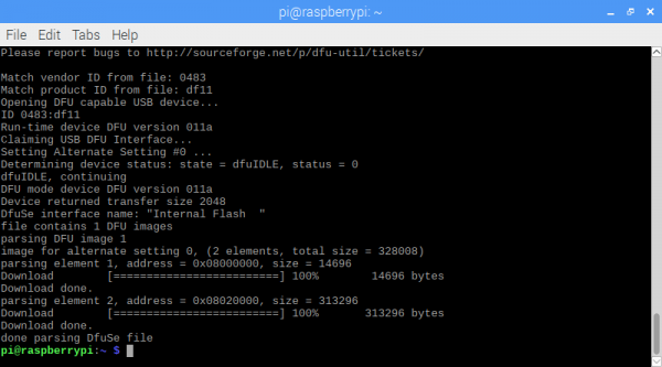
WiFi IR Blaster Hookup Guide

$
0
0

WiFi IR Blaster Hookup Guide a learn.sparkfun.com tutorial

Available online at: http://sfe.io/t817

Introduction

With the advent of WiFi-connected “smart” devices, IR remotes are quickly becoming a thing of the past. Why sort through a coffee table-full of remotes when you probably have a much smarter, WiFi-connected device device sitting conveniently in your hand?

The WiFi IR Blaster is designed to connect all of those old, legacy IR-controlled devices to a WiFi network – exposing them to a new method of control. Want to control your TV via a web-browser? Want to ask Alexa to mute your stereo? Want to schedule triggers to your IR-controlled LED strip? These are all applications that the WiFi IR Blaster is perfect for.

WiFi IR Blaster - ESP8266

WiFi IR Blaster - ESP8266

SPX-15000
$14.95

The WiFi IR Blaster combines an ESP8266 – a powerful WiFi/microcontroller SoC – with IR emitters and receivers. With built-in WiFi support, the ESP8266 can be programmed to provide an interface between HTTP, MQTT, TCP, etc. and infrared-controlled devices.

This tutorial will explain how to assemble the WiFi IR Blaster and it will detail how to program the ESP8266 using the Arduino IDE. Once complete, you’ll have a simple web server than can emit infrared signals at the click of a browser-page.

Bill of Materials

The WiFi IR Blaster includes the board, an infrared emitter and an infrared receiver. You’ll need a handful of other tools and components to get it powered and programmed:

Break Away Headers - Straight

Break Away Headers - Straight

PRT-00116
$1.50
20
SparkFun Beefy 3 - FTDI Basic Breakout

SparkFun Beefy 3 - FTDI Basic Breakout

DEV-13746
$14.95
6
Infrared Remote Control

Infrared Remote Control

COM-14865
$3.95
Break Away Male Headers - Right Angle

Break Away Male Headers - Right Angle

PRT-00553
$1.95
4

The SparkFun Beefy 3 - FTDI Basic Breakout is primarily used to program the ESP8266, but it’s also able to supply the 3.3V/300mA power required by the Blaster. Although you can use any 3.3V USB-to-serial converter, this is the one we recommend.

Headers – either right-angle or straight are the recommended interface between your board, the programmer, a breadboard, perfboard, etc.

If you don’t have an IR remote handy, the SparkFun IR RemoteCcontrol is a useful tool for testing. It may even accidentally work with your TV!

In addition to those components, you’ll need a soldering iron, solder, and general soldering accessories.

To add, you’ll also need a local WiFi network that you can connect your ESP8266 up to. It also helps to have a second device – smartphone or computer – that’s also connected to that network.

Hardware Overview

The WiFi IR Blaster is based around the ESP-12S ESP8266 module. This module equips the ESP8266 with a crystal, 4Mb flash, and PCB antenna – just about everything it needs to get going. The antenna sits under the SparkX logo, so try not to place anything that may interfere with WiFi signals near that area.

Top of IR Blaster board

Supporting the ESP8266 are a reset and general purpose button, a user LED, and an array of pin breakouts.

Of course, there’s also the IR emitter and detector. These components are packaged with the board, but not soldered in place. This allows you to solder both components at any angle your project requires. It also leaves the option to customize the board and spec out your own emitter and/or receiver.

IR emitter and receiver

The IR emitter is a Lite-ON LTE-302. It’s driven by an NPN transistor, which helps amplify the current through the LED.

The IR receiver is a TSOP38238. This is a simple IR receiver hard-coded to receive IR signals modulated at 38kHz.

Assembly Tips

Time to whip out a soldering iron! The IR emitter and receiver do not come soldered onto the WiFi IR Blaster. You’ll also need to solder headers into the programming header and at least power supply pins.

Both IR components are polarized– make sure youd solder them in in the correct orientation. Both components have a bulb-shaped bump protruding from one side, the bumps should both be facing towards the nearer edge of the board. Silkscreen on the board should also help orient the components.

IR Components and headers assembled

While you have your iron out, you may also want to solder headers into the 6-pin serial header and the 8-pin power/GPIO header. Which headers you solder into the board ultimately depends on your application. I like soldering in a male right-angle header to the 6-pin header, which makes attaching the USB-to-serial board easier. Straight male headers work well for plugging the board into a bread- or perf-board.

Powering the WiFI IR Blaster

The WiFi IR Blaster includes a 3.3V low dropout regulator which can supply up to 600mA and handle voltage inputs up to 6V. To use this regulator, connect your power source to the VIN pin.

Alternatively, a pair of 3.3V pins are broken out on both headers. This pin directly supplies the ESP8266, so it should remain regulated to the range of ESP8266: 3.0V-3.6V.

Powering via FTDI Header

The WiFi IR Blaster can be powered via the 3.3V pin on the 6-pin serial header. Voltage supplied to this pin should be regulated to 3.3V. You're power source will need to be able to supply at least 300mA, which most FTDI boards cannot do. We recommend the Beefy 3 FTDI Basic Breakout which can supply up to 600mA.

Removing the Standoff Edge

A pair of standoffs are provided towards the bottom of the WiFi IR Blaster. If you don’t need these standoffs, and want to save some space, the standoff board can be removed by breaking it along the v-score line.

Programming the ESP8266

The WiFi IR Blaster’s ESP8266 is designed to be programmed with a 3.3V FTDI Basic or a similar 6-pin USB-to-Serial converter. We recommend a Beefy 3 FTDI Basic Breakout if you’re powering the Blaster with the FTDI (see the note in the previous section for more information).

Plug your USB-to-serial converter in making sure you match the “GND” and “DTR” signals on the edge.

USB-to-serial converter connected to IR blaster board

Arduino Board Support

Before programming the WiFi IR Blaster's ESP8266, you'll need to install the ESP8266 Arduino board defintions. The board definitions can be found in the ESP8266 Arduino GitHub repository. For installation instructions, check out this section of the README.

The WiFi Blaster board definition is not included with the Arduino ESP8266 board files, but it can be uploaded to as a Generic ESP8266 Module. Verify your settings look like below:

Board: Generic ESP8266 Module
BoardGeneric ESP8266 Module
Flash ModeQIO
Debug LevelNone
Reset Methodck
CPU Frequency80 MHz
Flash Size4M (1M SPIFFS)
Debug PortDisabled
lwIP Variantv2 Prebuilt (MSS=536)
Crystal Frequency26 MHz
Flash Frequency40MHz
Upload Speed115200

Arduino board selection

Auto vs. Manual Reset Into Bootloader

In addition to the RX and TX pins, the FTDI’s DTR pin is used to reset the ESP8266 and get it into bootloader mode. The board includes circuitry to automatically reset and bootload the board; in most cases, you shouldn’t have to do anything special to program it.

The auto-reset circuit can be a little flaky, however. If the board isn’t taking a program, you may see an error like “error: espcomm_upload_mem failed”.

If this shows up repeatedly, you may need to manually reset into bootloader mode be holding pin 0 low while resetting the ESP8266:

  1. Hold down the “0” button
  2. Press and release the “RST” button
  3. Release the “0” button

The timing of this can be a little tricky. Try resetting it into bootloader mode, then quickly uploading your sketch.

Decreasing the upload speed baud rate to something around 115200 bps can also help improve the reliability of the reset circuit.

Testing the Receiver

ESP8266 IR Remote Arduino Library

IRremoteESP8266 -- an IR Arduino library specific to the ESP8266 -- gets our recommendation for sending and receiving IR signals with this board. You can download the library from their GitHub page, or by searching out IRremoteESP8266 in your Arduino library manager.

IRremoteESP8266 library manager install

The IR remote library includes an exhaustive collection of examples which demonstrate how to send and receive IR signals. To test out the receiver, open up the IRrecvDumpV2 example by navigating to the File > Examples > Examples from Custom Libraries > IRremoteESP8266 menu.

Before uploading the sketch, you need to modify the RECV_PIN pin definition on line 39. This sets the ESP8266 pin connected to your IR receiver. Set it to 13.

language:c
#define RECV_PIN 13

Once that modification has been made, upload away! (Make sure the board is set correctly to “NodeMCU 1.0 (ESP-12E Module)”.) Then open up the serial monitor and set the baud rate to 115200.

You should see a “IRrecvDumpV2 is now running and waiting for IR input on Pin 13” message print out. If you don’t try tapping the board’s reset button.

Then aim an IR remote at the board and hit a button. You should see a stream of data shoot by.

Example recv dump output from serial monitor

The most important bits of this output are the last 4 lines, which should look a lot like C variable declarations. For example:

uint16_t rawData[71] = {8994, 4428,  600, 522,  600, 520,  602, 520,  604, 1608,  606, 516,  606, 516,  606, 516,  606, 516,  606, 1604,  600, 1610,  604, 1606,  598, 524,  598, 1612,  602, 1610,  604, 1606,  598, 1614,  600, 1612,  602, 520,  602, 1608,  606, 514,  608, 514,  596, 524,  598, 524,  598, 524,  598, 524,  598, 1610,  604, 518,  604, 1606,  598, 1612,  600, 1610,  604, 1606,  596, 1616,  598, 35622,  8988, 2214,  598};  // NEC 10EFA05F
uint32_t address = 0x8;
uint32_t command = 0x5;
uint64_t data = 0x10EFA05F;

These lines will be used in the next example, where we test the emitter.

Sending IR Codes

Armed with the timing data for your desired IR command, load up the IRsendDemo example. Around line 42, replace the rawData array with the one you copied from the previous example. You shouldn’t have to modify the pin definition for the IR emitter – just double-check to make sure IR_LED is set to 4, which is the ESP8266 pin connected to the IR emitter.

With that change made, upload the code. Then point the IR emitter at your device. The emitter has a range of about 10 feet, so you may need to get a little close. It should receive a command every 6 seconds.

If your code is Sony- or NEC-encoded, you can also plug the value from data in the previous example to send an NEC or Sony command. This is quite a bit more efficient than sending the raw timing data.

Sending NEC Codes via Web Server

One last example which really begins to show the power of this module is the IRServer example. This sketch will connect your ESP8266 to WiFi and set it up as a web server. When the right HTTP endpoint is hit, it will send a desired command. So you can trigger your device from a web browser!

This example requires that you have an NEC-encoded signal to send.

Before uploading this example, plug your WiFi network’s SSID and password into the ssid and password variables.

Then adjust some of the static HTML in the handleRoot() function to send your desired code. This is a little tricky. You need to find your NEC code from the receive example – in my case it was 0x10EFA05F. You’ll also need to convert this value to decimal (here’s a calculator for that). In my case it was 284139615. Plug those two values into a new line of C-string'ed HTML. I added this line on line 59, for example:

language:c
              "<p><a href=\"ir?code=284139615\">Send 0x10EFA05F</a></p>" \

Then upload the code! Open the serial monitor to check on your ESP8266’s connection status. Once connected it should provide you an IP address.

On a device connected to the same WiFi network, plug that IP address into the address bar. You should be greeted with a page like this:

IR server web page

Then aim your IR Blaster at a device, and click your newly added link. Your signal should be routed from your phone or computer, over the WiFi airwaves, to the device you want to control.

Going Further – IR Controller Firmware

Exploring the IRRemoteESP8266 library is just the very tip of this WiFi IR Blaster iceberg. We highly recommend checking out the IR Controller ESP8266 firmware. This fully featured firmware combines IR send and receive functions with a web server. It monitors for received commands, and provides a handy interface to emit those back out with the ESP8266. There are even instructions for connecting the Blaster to an Alexa service.

IR controller web page example

If you give this firmware a spin, just remember you’ll need to specify the IR emitter and receiver pins. This is what I’ve set the pins varaibles to:

language:c
const int pinr1 = 13;                               // Receiving pin
const int pins1 = 4;                                // Transmitting preset 1
const int pins2 = 12;                               // Transmitting preset 2 (not used)
const int pins3 = 12;                               // Transmitting preset 3 (not used)
const int pins4 = 12;                               // Transmitting preset 4 (not used)
const int configpin = 5;                            // Reset Pin

// User settings are above here
const int ledpin = 0;                               // Built in LED defined for WEMOS people

You’ll also need to install a handful of libraries, which are all described in the Setup section of the README.

With those few modifications, you should be up-and-IR-controlling in no time!

Resources

Need more information on the WiFi IR Blaster? Checkout our GitHub repository and the rest of these documents:


learn.sparkfun.com | CC BY-SA 3.0 | SparkFun Electronics | Niwot, Colorado
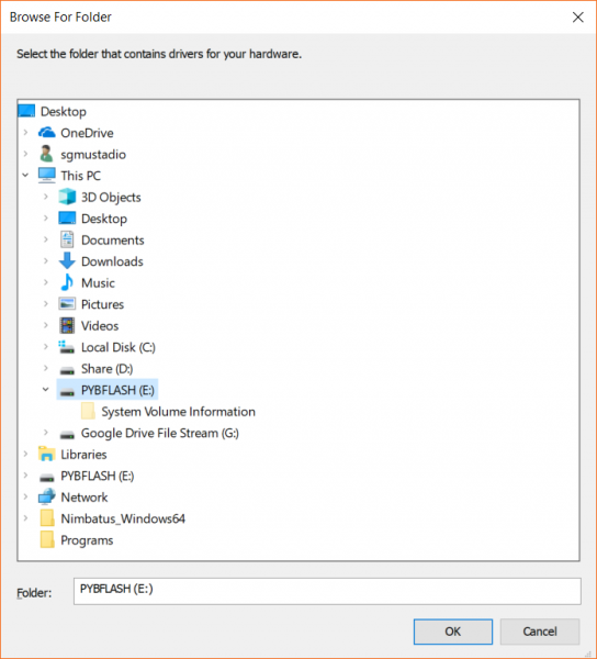
Qwiic IR Array (MLX90640) Hookup Guide

$
0
0

Qwiic IR Array (MLX90640) Hookup Guide a learn.sparkfun.com tutorial

Available online at: http://sfe.io/t805

Introduction

The Melexis MLX90640 (110° and 55° FOV) contains a 32x24 array of thermopile sensors creating, in essence, a low resolution thermal imaging camera. As the images show, you can detect surface temperatures from many feet away with an accuracy of ±1.5°C (best case). We’ve packaged the MLX90640 on an easy to use Qwiic board with mounting holes and a smattering of decoupling caps.

SparkFun IR Array Breakout - 110 Degree FOV, MLX90640 (Qwiic)

SparkFun IR Array Breakout - 110 Degree FOV, MLX90640 (Qwiic)

SEN-14843
$69.95
SparkFun IR Array Breakout - 55 Degree FOV, MLX90640 (Qwiic)

SparkFun IR Array Breakout - 55 Degree FOV, MLX90640 (Qwiic)

SEN-14844
$69.95

In this guide, we’ll go over how to connect your Qwiic IR Array with MLX90640 and get it communicating with Processing to produce a nice thermal image.

Required Materials

Not Uno Compatible: The MLX90640 requires complex calculations by the host platform. A regular Uno doesn't have enough RAM or flash to complete the complex computations required to turn the raw pixel data into temperature data. You will need a microcontroller with 20,000 bytes or more of RAM. We recommend a Teensy 3.1 or above. Make sure to grab headers if you get a headerless version of the Teensy.
Teensy 3.2

Teensy 3.2

DEV-13736
$19.80
61
Teensy 3.6 (Headers)

Teensy 3.6 (Headers)

DEV-14058
$33.25
2
Break Away Headers - Straight

Break Away Headers - Straight

PRT-00116
$1.50
20
Teensy 3.5 (Headers)

Teensy 3.5 (Headers)

DEV-14056
$28.95
1

We don’t have any Qwiic shields available for Teensy, so you should snag yourself a breadboard and a breadboard friendly Qwiic cable if you haven’t already to get the Teensy connected to the MLX90640.

Breadboard - Self-Adhesive (White)

Breadboard - Self-Adhesive (White)

PRT-12002
$4.95
36
Breadboard - Translucent Self-Adhesive (Clear)

Breadboard - Translucent Self-Adhesive (Clear)

PRT-09567
$4.95
14
Qwiic Cable - Breadboard Jumper (4-pin)

Qwiic Cable - Breadboard Jumper (4-pin)

PRT-14425
$1.50
Breadboard - Classic

Breadboard - Classic

PRT-00112
$9.95
12

Tools

Depending on your setup, you may need a soldering iron, solder, and general soldering accessories if you bought a headerless Teensy.

Solder Lead Free - 100-gram Spool

Solder Lead Free - 100-gram Spool

TOL-09325
$7.95
7
Weller WLC100 Soldering Station

Weller WLC100 Soldering Station

TOL-14228
$44.95

Suggested Reading

If you aren’t familiar with our new Qwiic system, we recommend reading here for an overview. Since we’ll also be using Processing in one of these demos, we’d recommend looking up the tutorial on hooking your Arduino up to Processing. We would also recommend taking a look at the following tutorials if you aren’t familiar with them.

How to Solder: Through-Hole Soldering

This tutorial covers everything you need to know about through-hole soldering.

Connecting Arduino to Processing

Send serial data from Arduino to Processing and back - even at the same time!

I2C

An introduction to I2C, one of the main embedded communications protocols in use today.

Hardware Overview

First, let’s check out some of the characteristics of the MLX90640 IR Array we’re dealing with, so we know what to expect out of the board. Keep in mind that there are two options for the field of view 110°x75° and 55°x35°

CharacteristicRange
Operating Voltage3V-3.6V
Current Consumption~18 mA
Measurement Range-40 °C - 85°C
Resolution&pm;1.5°C
Refresh Rate0.5Hz - 64 Hz
I2C Address0x33

Pins

The following table lists all of the MLX90640’s pins and their functionality.

PinDescriptionDirection
GNDGroundIn
3.3VPowerIn
SDADataIn/Out
SCLClockIn

Optional Features

The MLX90640 IR Array has pull up resistors attached to the I2C bus; both can be removed by cutting the traces on the corresponding jumpers on the back of the board, highlighted below.

I2C Pullup Jumper

I2C Pull Up Jumper

The onboard LED (highlighted below) will light up when the board is powered, and the sensor (also highlighted below) should be left uncovered in your application.

Power LED

Power LED

Hardware Assembly

Since we don’t have a Qwiic shield for the Teensy at this point in time, we’ll need to connect our Qwiic Infrared Array through the breadboard compatible Qwiic cable. Check out the following table if you’re unsure of how to connect your Qwiic cable. The Teensy 3.5 pinout is available here. For more pin assigments, refer to the Teensy's reference page.

ColorFunctionPin
BlackGroundAny GND pin
RedPower (3.3V)Any 3.3V pin
YellowClock19
BlueData18

Once you have your cable hooked up to the breadboard, go ahead and plug it into your MLX90640 IR Array and you’ll be ready to go.

MLX90640 Plugged into Breadboard

MLX90640 Plugged into Breadboard

Example Code

Note: This example assumes you are using the latest version of the Arduino IDE on your desktop. If this is your first time using Arduino, please review our tutorial on installing the Arduino IDE.

Teensyduino Add-On

If you haven’t used Teensy before, you’ll probably need to download and install the extension for the Arduino IDE called Teensyduino, located here.

Library

Melexis has written a library to control the Qwiic IR Array with MLX90640. You can obtain these libraries by clicking the below button, which also includes the SparkFun written example sketches from the GitHub repository. Just makes sure the associated files are in the same path when opening each example.

MLX90640 Library and Examples (ZIP)

Example 1 - Basic Readings

Once you’ve downloaded the example sketches and library, go ahead and open the first example under SparkFun_MLX90640_Arduino_Example-master>Firmware>Example1_BasicReadings>Example1_BasicReadings. To initialize the sensor, we first attempt to talk to the MLX90640 with the isConnected() function. Looking closer at our setup() loop reveals that we extract a set of paramaters from the MLX using MLX90640_DumpEE and MLX90640_ExtractParamaters. This only needs to be done once in the setup() loop before the board is ready to use, the code is shown below.

language:c
void setup()
{
  Wire.begin();
  Wire.setClock(400000); //Increase I2C clock speed to 400kHz

  Serial.begin(9600);
  while (!Serial); //Wait for user to open terminal
  Serial.println("MLX90640 IR Array Example");

  if (isConnected() == false)
  {
    Serial.println("MLX90640 not detected at default I2C addres. Please check wiring. Freezing.");
    while (1);
  }
  Serial.println("MLX90640 online!");

  //Get device parameters - We only have to do this once
  int status;
  uint16_t eeMLX90640[832];
  status = MLX90640_DumpEE(MLX90640_address, eeMLX90640);
  if (status != 0)
    Serial.println("Failed to load system parameters");

  status = MLX90640_ExtractParameters(eeMLX90640, &mlx90640);
  if (status != 0)
    Serial.println("Parameter extraction failed");

  //Once params are extracted, we can release eeMLX90640 array
}

Once you’ve selected your board and serial port, upload the sketch to your Teensy. Then open the serial monitor set at 115200 baud. The output should look something like the below image, with the temperature values of each pixel being displayed in °C.

Example 1 Output

Example 1 Output

Example 2 - Output To Processing

Note: Processing is a software that enables visual representation of data, among other things. If you've never dealt with Processing before, we recommend you also check out the Arduino to Processing tutorial. Follow the below button to go ahead and download and install Processing.

Download Processing IDE

This next example involves the Processing IDE. Processing listens for serial data, so we’ll need to get our Arduino producing serial data that makes sense to Processing. To pull up the next example, go to SparkFun_MLX90640_Arduino_Example-master>Firmware>Example2_OutputToProcessing>Example2_OutputToProcessing to open the example sketch. This sketch simply prints a comma separated list of our temperatures over serial for Processing to listen to.

Once this sketch is uploaded, we need to tell Processing how to turn this data into a visualization. The Processing sketch to do this is located in the same folder as Example 2. So go to the sketch folder to open the MLXHeatCam file in Processing. Attempting to run the sketch will show us available serial ports in the debug window.

COM Port Selection

Identify which serial port your Teensy is on. For instance, my Teensy is on COM6, which corresponds to [1] in the above image, so I will need to change 0 to 1 in the following line to ensure Processing is listening in the right location.

language:c
myPort = new Serial(this, Serial.list()[0], 115200);

Once I’ve done this, we should be able to run the Processing sketch and it will give us a nice visualization of the pixels on our Qwiic IR Array with MLX90640. Move your face or hand in front of the sensor and see what it looks like on the screen. The output should look similar to the image below. Note that the camera can only hit about 4 Hz due to the data rate over I2C. The hypothetical refresh rate of the MLX90640 is 64 Hz, but unless you have a microcontroller capable of a much faster I2C rate, you won’t be hitting framerates anywhere near that.

IR Camera

IR Camera Display

Resources and Going Further

Now that you’ve successfully got your Qwiic IR Array with MLX90640 up and running, it’s time to incorporate it into your own project!

For more information, check out the resources below:

Need some inspiration for your next project? Check out some of these related tutorials:

FLIR Lepton Hookup Guide

See the invisible world of infrared radiation using the FLIR Dev Kit and Raspberry Pi.

MLX90614 IR Thermometer Hookup Guide

How to use the MLX90614 or our SparkFun IR Thermometer Evaluation Board to take temperatures remotely, over short distances.

Qwiic GRID-Eye Infrared Array (AMG88xx) Hookup Guide

The Panasonic GRID-Eye (AMG88xx) 8x8 thermopile array serves as a functional low-resolution infrared camera. This means you have a square array of 64 pixels each capable of independent temperature detection. It’s like having thermal camera (or Predator’s vision), just in really low resolution.

learn.sparkfun.com | CC BY-SA 3.0 | SparkFun Electronics | Niwot, Colorado


LilyPad Basics: Powering Your Project

$
0
0

LilyPad Basics: Powering Your Project a learn.sparkfun.com tutorial

Available online at: http://sfe.io/t668

Introduction

In this guide, we will discuss options for powering your LilyPad projects (both e-sewing and Arduino-based), battery safety and care, and how to calculate and consider power constraints on your projects. Creating wearable and fabric projects have their own considerations and we’ll also cover when it makes sense to switch from conductive thread connections to wired connections.

LilyPad projects are often wearable or portable, which means using a battery to take the final project on the go. However, there are a few options for powering your projects beyond just plugging in a battery. Read on for sections detailing different power sources and options available for working with the system.

We’ve compiled some tips for you, to help decide what power source to use, how long it will last on battery power, and other considerations. Knowing how much voltage your project needs, the total current draw of the LilyPad boards you are using in your project, and battery capacity will help you choose the best option for optimal operation.

Suggested Reading

If you aren’t familiar with the following concepts, we recommend checking out these tutorials before continuing.

Voltage, Current, Resistance, and Ohm's Law

Learn about Ohm's Law, one of the most fundamental equations in all electrical engineering.

Battery Technologies

The basics behind the batteries used in portable electronic devices: LiPo, NiMH, coin cells, and alkaline.

How to Power a Project

A tutorial to help figure out the power requirements of your project.

Electric Power

An overview of electric power, the rate of energy transfer. We'll talk definition of power, watts, equations, and power ratings. 1.21 gigawatts of tutorial fun!

What is a Battery?

An overview of the inner workings of a battery and how it was invented.

Calculating Power Needs: Operating Voltage

Most LilyPad projects can operate easily on a 3.7V rechargeable Lithium Polymer battery. The microcontroller or main sensor or component that each LilyPad board is built around has its particular operating voltage needs documented in its datasheet. You can find the datasheet for a product in the Documents tab of the catalog page on SparkFun.com.

SparkFun Product Page and the Documents Tab

Example of the documents tab for the LilyPad Arduino USB - ATmega32U4 Board.

When reading the datasheet, look for Operating Voltages - the document will typically provide a minimum and maximum voltage range. If there is no datasheet attached to the product, you can also check the schematic.

If you don’t give a board a large enough voltage, it may not operate correctly (you could see strange behavior in how code runs on a LilyPad Arduino, odd readings from sensors in the Serial Port, or dim LEDs). If you project is receiving voltage above its recommended range, you could potentially damage the board or reduce the operating time significantly. Make sure the power source you choose for your project is within the board’s recommended range.

Here is a list of common LilyPad Boards and their needs. The middle column displays the regulated voltage on the board from the input voltage. If you choose a board that does not include a built-in regulator, you will need to pay close attention to your power source to make sure it is compatible with your project. The last column shows the input voltage that each board can take, notice that this can be above 3.3V, the suggested operating voltage of a LilyPad project.

BoardVoltage Regulation Input Voltage
LilyTinyNo1.8V - 5.5V
LilyTwinkle / LilyTwinkle ProtoSnapNo1.8V - 5.5V
LilyMini ProtoSnap3.3V1.62V - 3.63V, 5.0V through USB
LilyPad Arduino SimpleNo2.7V - 5.5V
LilyPad Arduino SimpleSnap3.3V2.7V - 5.5V
LilyPad Arduino USB - ATmega32U4 Board3.3V2.7V - 5.5V
Lilypad USB Plus3.3V1.8V - 5.5V
LilyPad Arduino 328 Main BoardNo2.7V - 5.5V
LilyPad XBee3.3V1.8V - 9V
LilyPad Simblee BLE Board - RFD771013.3V1.8V – 3.6V
LilyPad MP33.3V3.7V - 6V

Calculating Power Needs: Current Draw

In addition to checking the operating voltage of the LilyPad boards in your project, you’ll also want to take a look at the current your project will draw compared to the current your microcontroller or battery source can provide.

The current draw of your project depends on the total number of LilyPad boards you have chosen to use in your project and applies to both LilyPad Arduino-controlled circuits and e-sewing projects. If your power supply or battery does not provide the current your project needs, the circuit may start acting in strange or unpredictable ways.

As with voltage, you can check the datasheets of the individual LilyPad boards to estimate what your project will use.

For projects using a LilyPad Arduino, check how much current each individual I/O (input/output) sew tab can provide - the amount of LilyPad boards, such as LEDs, will be limited by this number. For most LilyPad Arduinos this is 40mA per I/O sew tab.

It’s also better practice to round up and assume your circuit will need more current than to not provide enough current.

If your project uses components that require a lot of current, like motors or large amounts of LEDs, you may need to readjust your power supply choice or even use a separate supply for the LilyPad Arduino and the current-hungry boards.

As you gain experience working with LilyPad boards, it will be easy to estimate the amount of current your project requires by looking at the boards' datasheets and doing some math. You can also find out exactly how much current your project uses by measuring it with a digital multimeter or variable DC power supply that has a readout for current.

Read World Example: LilyPad LEDs and LilyTiny

Let’s explore an example of a frequently asked question about LilyPad projects: How many LEDs can I connect to a LilyTiny (or LilyTwinkle) board?

A typical LilyPad LED uses 20mA of current at full brightness. Multiply that by the number of LEDs you’re using, add 10mA for the LilyPad that’s running everything, and you’ll have an estimate of your average current draw.

Example:

A project with 10 LilyPad LEDs connected to a LilyTiny Board

20mA * 10 + 10mA = 210mA

For more detailed information on working with LilyPad LEDs, take a look at our Powering LilyPad LED Projects.

Powering LilyPad LED Projects

December 17, 2016

Learn how to calculate how many LEDs your LilyPad project can power and how long it will last.

Considering Conductive Thread Resistance

Now that you’ve done your calculations, there is another factor to consider: conductive thread resistance. Unlike copper wire, which has very little resistance, conductive thread’s resistance will vary depending on the metal used to make the thread and the thickness of the thread. Many conductive threads list resistance in Ohms/Ft. The lower this number is, the better, because less resistance means more electricity can get through to the components used in your project.

You may expect your project to work perfectly, but the resistance of your connections over distance may cause some additional complications in your circuit.

Solid wire, stranded wire, and stainless steel conductive thread

The basic electrical property Ohm’s Law states that running an electrical current through a material high in resistance causes the voltage to drop. The higher the current, the greater the voltage drop. This means that even though a LiPo battery powering your LilyPad may put out 3.7 volts, by the time it gets through the thread to your components, it may drop to 3.0 volts or less. Many electrical components, such as LEDs, need a certain voltage to function properly. To minimize voltage drop, we’ll need to decrease the resistance of the power connections. There are a few ways to do this:

  • Keep the length of the power connections as short as possible. Because the resistance increases with length, if you reduce the length, you’ll reduce the resistance.

  • Reduce the resistance of the thread itself. Thicker thread has a lower resistance than thinner thread, and using multiple strands at a time reduces the resistance even further.

Tip:

Use a non conductive thread to stitch bundled thread (either placed together or braided) to your base fabric. Leave enough open spaces in the stitching so you are able to stitch conductive thread to the larger thread bundle when connecting components. This video from e-textile expert Lynne Bruning shows this technique at around the 4:10 mark:

Conductive Thread Alternatives

For large projects that require thread to travel long distances, projects with a lot of power-hungry pieces such as a large amount of LilyPad Pixel Boards, or in spots where thread may break under stress, here are some alternatives that work well for wearables:

Conductive Ribbon

Specialty nylon ribbon with flexible stranded wire woven into it is a great alternative to conductive thread with low resistance. You will need to solder to the tinsel within the ribbon in order to use in a project.

Conductive Ribbon - 3-Conductor (1 yard)

Conductive Ribbon - 3-Conductor (1 yard)

DEV-10172
$5.95

Conductive Fabric Traces

You can create your own lower resistance traces using thin strips of conductive fabric. We recommend using iron-on adhesive to attach to fabric or ribbon, then using conductive thread to hand stitch components to the traces.

Conductive Fabric Used as Traces Between Components

Don’t forget to insulate the fabric traces as you would conductive thread.

Stranded Wire

Another alternative is to switch from conductive thread to traditional wire. Wire has a much lower resistance than thread, allowing you to use more LEDs than a conductive thread circuit. You’ll have to switch from sewing to soldering, but it’s easy to solder wires to the same sew tabs to which you would normally connect thread.

Ribbon Cable - 6 wire (15ft)

Ribbon Cable - 6 wire (15ft)

CAB-10646
$2.95
2

Wire is prone to breaking if it is flexed repeatedly. For wearable projects that require maximum flexibility, use stranded wire (not solid), and look for special silicone-jacketed wire that is extremely flexible. For projects that will be washed, water may wick into exposed stranded wire, becoming trapped and potentially corroding it over time. Apply a small dab of silicone sealant to the cut ends of the wire to prevent this from happening.

If you have never soldered before or worked with wire, we recommend visiting the following tutorials.

How to Solder: Through-Hole Soldering

This tutorial covers everything you need to know about through-hole soldering.

Working with Wire

How to strip, crimp, and work with wire.

Once you’ve identified your project’s power needs and considerations, it’s time to move on to choosing a power source for your project.

Power Options: Using a Built-In USB Connector

While working on programming a LilyPad Arduino project, you can use the power supplied by the USB cable connecting your LilyPad Arduino to your computer. Make sure the slide switch on the LilyPad Arduino is set to the ON position to upload code and power up your board while prototyping.

Built-In Power Switch in a LilyPad

This method works for LilyPad Arduinos with a built-in micro USB port and those with programming headers and LilyPad FTDI Basic Breakout.

LilyPad boards with a micro USB connector can be powered by 5V Lithium Ion battery packs such as the ones used in the Spectacle line or for backups for cell phone charging.

Lithium Ion Battery Pack - 2.2Ah (USB)

Lithium Ion Battery Pack - 2.2Ah (USB)

TOL-14169
$6.95
2

If your project is not portable or wearable (such as a wall hanging or permanent installation) you may choose to utilize a 5V wall adapter power supply for your project. Plugging into a dedicated power source will eliminate the need to constantly swap out or recharge batteries in your project.

Wall Adapter Power Supply - 5.1V DC 2.5A (USB Micro-B)

Wall Adapter Power Supply - 5.1V DC 2.5A (USB Micro-B)

TOL-13831
$7.95
15
Wall Adapter Power Supply - 5V DC 2A (USB Micro-B)

Wall Adapter Power Supply - 5V DC 2A (USB Micro-B)

TOL-12890
$5.95
16

The LilyPad Simple Power is a board that offers you some flexibility - it can accommodate a rechargeable battery or a micro USB cable attached to a wall adapter for LilyPad projects that do not have a built-in battery connector.

LilyPad Simple Power

LilyPad Simple Power

DEV-11893
$9.95

Power Options: Rechargeable Lithium Polymer Batteries

Many LilyPad products come equipped with a JST connector designed attach a 3.7V Lithium Polymer (LiPo) battery. These boards include a built-in battery charging circuit to recharge the LiPo when connected to a computer or wall wart via a USB connection.

LilyPad Arduino USB - ATmega32U4 Board

LilyPad Arduino USB - ATmega32U4 Board

DEV-12049
$24.95
7
LilyPad ProtoSnap Plus

LilyPad ProtoSnap Plus

DEV-14346
$39.95
LilyPad MP3

LilyPad MP3

DEV-11013
$49.95
4
LilyPad Arduino Simple Board

LilyPad Arduino Simple Board

DEV-10274
$19.95
LilyPad Simblee BLE Board - RFD77101

LilyPad Simblee BLE Board - RFD77101

DEV-13633
$24.95
2
LilyPad Simple Power

LilyPad Simple Power

DEV-11893
$9.95

SparkFun carries a variety of 3.7V Lithium Polymer batteries that are compatible with the LilyPad system. The capacity of the battery will depend on the intended run time of your project, size constraints, and other factors.

Lithium Ion Battery - 2Ah

Lithium Ion Battery - 2Ah

PRT-13855
$12.95
3
Lithium Ion Battery - 1Ah

Lithium Ion Battery - 1Ah

PRT-13813
$9.95
6
Lithium Ion Battery - 400mAh

Lithium Ion Battery - 400mAh

PRT-13851
$4.95
9
Lithium Ion Battery - 850mAh

Lithium Ion Battery - 850mAh

PRT-13854
$9.95
2
Lithium Ion Battery - 6Ah

Lithium Ion Battery - 6Ah

PRT-13856
$29.95
5
Lithium Ion Battery - 110mAh

Lithium Ion Battery - 110mAh

PRT-13853
$4.95
1
E-Textiles Battery - 110mAh (2C Discharge)

E-Textiles Battery - 110mAh (2C Discharge)

PRT-13112
$6.95
5

.

Using a LiPo Battery and Battery Charging

Each LilyPad board with charging capabilities has a default charge rate. If this default charge current is set to 100mA, so a 100mAh battery will recharge in one hour, a 1000mAh battery in 10 hours, etc. Since the board is set to charge at a rate of 100mA, we do not recommend connecting a lower capacity LiPo battery (i.e. 40mAh LiPo battery) to charge.

To recharge an attached battery, plug the board into a USB power source. While the battery is charging, the “CHG” LED will illuminate. When the battery is fully charged the LED will turn off.

Connecting a Battery

Inserting a LiPo battery into the JST port on a LilyPad ProtoSnap Plus

It is safe to leave a LiPo battery attached to the board permanently, even with USB power applied. The battery will not be overcharged. We recommend you do not leave a charging battery unattended.

The battery connector can be a tight fit and difficult to remove; when disconnecting a battery never pull on the wires. Use a pair of needle nose pliers or cutters along the plastic to gently pull the plug out of the connector.

Remove LiPo Battery

Tip: there are two small “nubs” on the top of the plastic battery connector that can be shaved off with a hobby knife to make the battery easier to remove.

LiPo Battery Safety and Care

While LiPo batteries are a great option for providing rechargeable power to your project, they do have some safety considerations. This section will cover tips for safe handling and use of LiPos for your projects.

Storage

  • Always store your batteries in and enclosure free of sharp objects. When installing a battery in your project, take care to keep it away from parts of your project that could pinch, poke, or strain the battery.

  • Do not transport or store a LiPo battery with metal objects, such as hairpins, necklaces, or any other conductive object or material.

  • Keep or store the battery in a cool and dry place/environment while installed in a project or in storage. If you are not planning to use your project for a long time, remove the battery and store it separately.

Keep Away from Heat and Moisture

  • Keep your LiPo battery away from environments that will damage it. Do not immerse a LiPo battery in liquids. Remove the battery from your project if it needs to be washed.

  • Do not use or store the battery near any source of heat. To secure a battery to your project, velcro is a temporary option or sew into a pouch or place in a plastic enclosure. Never iron or hot glue directly on or around a LiPo battery.

Strain Relief

One of the down sides to using these LiPo batteries is their fragile power connections. These type of batteries are manufactured for a permanent install in devices, and not being removed often as can sometimes happen with wearables. It can be easy to accidentally pull or break the power wires from the terminals on the safety circuit built into the battery.

You can provide strain relief to the wires by placing them to the side and securing with electrical tape - this will help with strain on the connection to the battery when pulling on them to remove.

Electrical tape around the wires of a LiPo for strain relief

Inspect Battery Before Each Use

  • Short circuits or damage to LiPo batteries may not always be noticeable - check the battery for puffiness, heat, or other changes. If the battery looks damaged, remove immediately.

  • If the battery gives off an odor, generates heat, becomes discolored or deformed, or in any way appears abnormal during use, recharging, or storage, immediately remove it from your project or battery charger and stop using it. Make sure to dispose of your batteries properly - do not throw them in the trash! Contact your local e-waste disposal organization for details on how to discard batteries in your area.

Power Options: Coin Cell Batteries

The LilyPad system includes boards that hold a single 3V CR2032 coin cell battery. These batteries are typically single use, but some rechargeable coin cell batteries may work in the holders.

Coin Cell Battery - 20mm (CR2032)

Coin Cell Battery - 20mm (CR2032)

PRT-00338
$1.95

The LilyPad product line includes a standalone battery holder with a switch that can be connected to a customized project, as well as built into the LilyMini board, and available in some ProtoSnap products. SparkFun also carries a non-LilyPad coin cell battery holder without sew tabs for projects that need a small footprint or for users who want to solder.

LilyPad Coin Cell Battery Holder - Switched - 20mm

LilyPad Coin Cell Battery Holder - Switched - 20mm

DEV-13883
$1.95
9
Coin Cell Battery Holder - 20mm (Sewable)

Coin Cell Battery Holder - 20mm (Sewable)

DEV-08822
$1.25
4
LilyPad LilyMini ProtoSnap

LilyPad LilyMini ProtoSnap

DEV-14063
$14.95
2
LilyTwinkle ProtoSnap

LilyTwinkle ProtoSnap

DEV-11590
$14.95
1

Battery Safety and Care

This section will cover tips for safe handling and use of coin cell batteries for your projects.

Storage

  • Do not transport or store a coin cell battery with metal objects, such as hairpins, necklaces, or any other conductive object or material. Do not store loose coin cell batteries together - they can make contact with each other and short circuit and discharge.

  • Keep or store the battery in a cool and dry place/environment while installed in a project or in storage. If you are not planning to use your project for a long time, remove the battery and store it separately.

Keep Away from Heat and Moisture

  • Keep your coin cell battery away from environments that will damage it. Do not immerse a coin cell battery in liquids. Remove the battery from your project if it needs to be washed.

  • Do not use or store the battery near any source of heat. To secure a battery to your project, use a specialty battery holder, sewn pouch, or place in a plastic enclosure. Never solder directly to a coin cell battery; if you need to solder one into a project, use a special battery holder or purchase a battery with solder tabs created for this purpose.

Inspect Battery Before Each Use

  • Short circuits or damage to coin cell batteries may not always be noticeable - check the battery for puffiness, heat, or other changes. If the battery looks damaged, remove immediately.

  • If the battery gives off an odor, generates heat, becomes discolored or deformed, or in any way appears abnormal during use, recharging, or storage, immediately remove it from your project or battery charger and stop using it. Make sure to dispose of your batteries properly - do not throw them in the trash! Contact your local e-waste disposal organization for details on how to discard batteries in your area.

How Long Will My Project Run on Battery Power?

To figure out how long your project will run on battery power, you need to know two things:

  • how much current your project uses
  • the capacity of your battery

Battery capacity is given in milliamp-hours (mAh). This number tells you how many milli-amps (mA) a full battery can provide for one hour before it’s empty. The e-Textiles Battery that comes with most LilyPad Arduino kits has a 110mAh capacity. For many projects, especially ones with a large number of components such as LEDs, you will probably want to use a higher capacity battery for a longer run time.

To find out how long a battery will last, use this formula:

Hours = Battery mAh / Project mA

Thus, an e-Textile battery will only power the project for approximately half an hour. Here’s an instance where a larger capacity battery would make sense, if the project needs to operate for a long time, such as during an event or showcase. The trade-off is that a higher capacity battery is also physically larger – make sure to plan accordingly for proper battery storage/attachment on your project to reduce strain on the wires and fabric.

Here are some typical runtimes for various SparkFun batteries and numbers of LilyPad LEDs/LilyPixels:

Number of LEDs1251020
Battery NameBattery mAhHours of Operation
Polymer Lithium Ion Battery - 40mAh401.30.80.40.20.1
E-Textiles Battery - 110mAh (2C Discharge)1103.72.21.00.50.3
Coin Cell Battery - 20mm (CR2032) * 2508.35.02.31.2.61
Polymer Lithium Ion Battery - 400mAh40013.38.03.61.91.0
Polymer Lithium Ion Battery - 850mAh85028.317.07.74.02.1
Polymer Lithium Ion Battery - 1000mAh100033.320.09.14.82.4
Polymer Lithium Ion Battery - 2000mAh200066.740.018.29.54.9
Polymer Lithium Ion Battery - 6Ah6000200.0120.054.528.614.6

* Note: the Coin Cell Battery is non-rechargeable.

Resources and Going Further

Need more information related to LiPo batteries and wearable projects? Check out some of these related tutorials:

How Lithium Polymer Batteries are Made

We got the opportunity to tour the Great Power Battery factory. Checkout how LiPos are made!

LilyPad Simple Power Hookup Guide

A basic guide for getting started using the LilyPad Simple Power with LiPo batteries.

Insulation Techniques for e-Textiles

Learn a few different ways to protect your conductive thread and LilyPad components in your next wearables project.

Planning a Wearable Electronics Project

Tips and tricks for brainstorming and creating a wearables project.

learn.sparkfun.com | CC BY-SA 3.0 | SparkFun Electronics | Niwot, Colorado
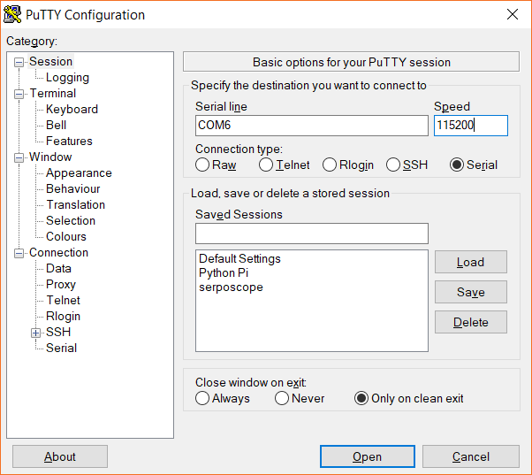
MicroPython Programming Tutorial: Getting Started with the ESP32 Thing

$
0
0

MicroPython Programming Tutorial: Getting Started with the ESP32 Thing a learn.sparkfun.com tutorial

Available online at: http://sfe.io/t659

Introduction

In this guide, we will walk through the process of setting up MicroPython on the ESP32 Thing and writing some example programs. Each “experiment” will show you how to wire up an example circuit and then control it using MicroPython.

Running MicroPython on the ESP32 Thing

What is MicroPython?

MicroPython is a lean implementation of the Python 3 programming language that has been pared down to run efficiently on microcontrollers. Python is a relatively simple (but powerful) language that is easy for beginners to pick up and has been gaining popularity in schools as an introductory language. MicroPython has nearly all of the features of Python, which means that interacting with hardware is now easily accessible to beginners and seasoned Python programmers alike.

Why the ESP32 Thing?

MicroPython is supported on many different microcontroller platforms, and more are being added all the time. The ESP32 is a great tool for learning MicroPython, as it has a powerful controller (240 MHz) with lots of RAM (520 kB). Additionally, the ESP32 has a built-in WiFi module, which makes networking and connecting to the Internet quite easy. All this is packaged up into a development board for you on SparkFun’s ESP32 Thing.

Note: This guide uses MicroPython version: esp32-20180822-v1.9.4-479. At the time of this writing, Bluetooth on the ESP32 is not supported by MicroPython.

Required Materials

To work through the activities in this tutorial, you will need a few pieces of hardware:

Suggested Reading

If you aren’t familiar with the following concepts, we recommend checking out these tutorials before continuing:

What is a Circuit?

Every electrical project starts with a circuit. Don't know what a circuit is? We're here to help.

Voltage, Current, Resistance, and Ohm's Law

Learn about Ohm's Law, one of the most fundamental equations in all electrical engineering.

How to Use a Breadboard

Welcome to the wonderful world of breadboards. Here we will learn what a breadboard is and how to use one to build your very first circuit.

ESP32 Thing Hookup Guide

An introduction to the ESP32 Thing's hardware features, and a primer on using the WiFi/Bluetooth system-on-chip in Arduino.
Please note: If you have trouble seeing any of the images throughout this tutorial, feel free to click on it to get a better look!
Python Logo

Hardware Overview

ESP32 Thing Pinout

The ESP32 has a number of features, such as:

One I2C, two of the UART interfaces, and one of the SPI interfaces can be assigned to any pin your project requires. However, there are a few hardware features (namely the ADC and DAC) that are assigned static pins. The graphical reference below helps demonstrate where you can find those peripherals.

ESP32 Thing Graphical DataSheet

Click the image for a closer look.

Input Only Pins: 34-39

Pins 34, 35, 36, 37, 38 and 39 cannot be configured as outputs, but they can be used as either digital inputs, analog inputs, or for other unique purposes. Also note that they do not have internal pull-up or pull-down resistors, like the other I/O pins.

GPIO pins 36-39 are an integral part of the ultra low noise pre-amplifier for the ADC – they are wired up to 270pF capacitors, which help to configure the sampling time and noise of the pre-amp.

Schematic close up of pins 34-39

From the ESP32 Thing Schematic: GPIO 36-39 are tied together with caps. Those and pins 34 and 35 are input only!

ESP32 Thing Board Overview

The ESP32 Thing breaks out most of the pins on the ESP32 chip and gives you access to a few extra features, such as a LiPo battery charger, 4 MB of flash memory, an FTDI USB-to-Serial chip, and a user-controlled LED and button.

Annotated overview of the ESP32 Thing

Powering the ESP32 Thing

The easiest ways to power the ESP32 Thing is through either the onboard USB connector or through the single-cell LiPo battery connector. Note that if a battery and USB are connected at the same time, the USB connection will charge the LiPo at a rate up to 500 mA.

⚡ The ESP32's operating voltage range is 2.2 to 3.6V. Under normal operation the ESP32 Thing will power the chip at 3.3V. The I/O pins are not 5V-tolerant! If you interface the board with 5V (or higher) components, you'll need to do some level shifting.

The 3.3V regulator on the ESP32 Thing can reliably supply up to 600mA, which should be more than enough overhead for most projects. The ESP32 can pull as much as 250mA during RF transmissions, but we’ve generally measured it to consume around 150mA, even while actively transmitting over WiFi. The output of the regulator is also broken out to the sides of the board (the pins labeled 3V3). These power pins can be used to supply external components.

Overview of the ESP32 Thing's power pins

In addition to USB and battery connectors, the VBAT, and VUSB pins are all broken out to both sides of the board. These pins can be used as an alternative supply input to the ESP32 Thing. The maximum, allowable voltage input to VUSB is 6V, and VBAT should not be connected to anything other than a single-cell LiPo battery. Alternatively, if you have a regulated voltage source between 2.2V and 3.6V, the “3V3” lines can be used to directly supply the ESP32 and its peripherals.

Setup

Serial Terminal Program

To communicate with the Read–Eval–Print Loop (REPL) running on the ESP32, you will need to install a serial terminal program for your particular operating system (OS). The following tutorial makes several good recommendations as to which programs to use for the 3 major operating systems:

Serial Terminal Basics

September 9, 2013

This tutorial will show you how to communicate with your serial devices using a variety of terminal emulator applications.

Text Editor

At the time of this writing, no major integrated development environments (IDEs) support MicroPython for the ESP32 (for example, Mu was developed for MicroPython but does not support the ESP32). As a result, you will need to write code in a raw text editor and then save the files as somename.py. Some recommended text editors that work well for writing code include:

Load MicroPython on the ESP32 Thing

Unfortunately, the ESP32 Thing does not come ready to run MicroPython programs out of the box. To run MicroPython on the ESP32, you will need to first load the interpreter on it. To do that, follow the steps outlined in the How to Load MicroPython on a Microcontroller Board (specifically, the steps found in the ESP32 Thing section).

New!

How to Load MicroPython on a Microcontroller Board

September 4, 2018

This tutorial will show you how to load the MicroPython interpreter onto a variety of development boards.

Install Python on Your Computer

In order to upload MicroPython programs to the ESP32, we will use a tool called ampy, which is a Python script that can read and write files to a MicroPython board over a serial connection. Because ampy is a Python script that runs on a host computer, we will need to install Python.

Instructions for installing Python can be found at python.org. Download and run the installer for your OS, or use your OS’s package manager to install Python (if you are on Linux). Ampy will run with Python 2 or Python 3, so choose whichever version you like (we recommend Python 3, as MicroPython is based on Python 3, so the language will be similar).

If you are installing on Windows, make sure the “Add Python <x.x> to PATH” checkbox is selected.

Add Python to PATH Checkbox

For more information on using Python on windows, see this link.

Install ampy

Once you have installed Python, open a terminal for your host computer, and enter the following command:

language:shell
pip install adafruit-ampy

You should see a printout showing that ampy was downloaded and installed.

Installing ampy

REPL (Hello, World!)

One of the easiest ways to interact with MicroPython running on the ESP32 is to enter commands via the REPL over a serial connection. This can be extremely helpful if you want to test out various parts of code before writing them down in a (slightly more permanent) text document that is then uploaded to the ESP32.

To start, connect the ESP32 Thing to your computer using a USB micro-B cable. If you are on Windows, open the Device Manager and find out which COM port your ESP32 Thing is associated with (for example, COM7). On macOS, it will likely be /dev/cu.usbserial-<some letters/numbers>, and on Linux, it’s probably something like /dev/ttyUSB0.

Open your Serial Terminal program of choice and connect to the ESP32 using the following connection details:

  • Speed: 115200 bits per second
  • Data Bits: 8
  • Parity: None
  • Stop Bits: 1

Once you have a connection, press enter once to get a REPL command prompt (>>>).

Getting a REPL command prompt from MicroPython

When you see that command prompt, enter the following commands one at a time:

language:shell
import machine
led = machine.Pin(5, machine.Pin.OUT)
led.value(1)

This should turn on the LED found on the ESP32 Thing (the blue LED located by pin 5).

Blinking the LED on the ESP32 Thing

Type the following command to turn it off:

language:shell
led.value(0)

Turning the ESP32 Thing LED on and off with MicroPython

Code to Note

The first thing we typed was import machine. machine is the MicroPython module that gives us control of the various general purpose input/output (GPIO) pins and special functions, such as I2C and interrupts. We use the keyword import to make all of the functions in the machine module available for us to use.

We then create a machine.Pin object and store it in the label led. When defining a machine.Pin object, we supply a number of arguments, including which pin number we want to use (the pin numbers can be found in white numbers on the side of the ESP32 Thing) and how we want to use that pin (e.g. as an input or output).

Because we set the pin as an output (as given by machine.Pin.OUT), we can drive the pin to logic low (0 V) or logic high (3.3 V) by setting its value to 0 (logic low) or 1 (logic high). To drive the pin high, we write led.value(1). This has the effect of turning on the LED.

Similarly, we can turn the LED off with led.value(0), which sets the pin to 0 V.

Experiment 1: Digital Input and Output

In the REPL section, we saw how to control an LED by individually calling commands in the REPL. This time, we are going to show two examples: how to respond to a button press and how to blink the onboard LED by writing code in a text editor and uploading that file to the ESP32.

There is one minor problem with MicroPython on the ESP32 that we will address in this experiment: if your code includes a forever loop, the MicroPython interpreter will continue to run your code (forever!), which means we never get a REPL prompt. The only way to stop a forever loop like this is to open a serial connection to the ESP32 and send it a ctrl + c command to terminate the running program.

The ampy tool requires REPL to upload new programs, so if the ESP32 is stuck running one of our programs, you will not be able to upload a new program. In the following experiment, we will build a tool that allows us to press the ESP32 Thing’s onboard button (labeled 0 on the board) to stop our program and return to REPL.

Hardware Connections

Good news! We can do this experiment with just the ESP32 Thing board by itself.

Plug the ESP32 Thing into your computer via USB cable

Code Part 1: Push Button, Get REPL

In your text editor of choice, enter the following code:

language:python
import machine
import sys
import utime

# Pin definitions
repl_button = machine.Pin(0, machine.Pin.IN, machine.Pin.PULL_UP)

# Wait for button 0 to be pressed, and then exit
while True:

    # If button 0 is pressed, drop to REPL
    if repl_button.value() == 0:
        print("Dropping to REPL")
        sys.exit()

    # Do nothing
    utime.sleep_ms(1)

Save the code with a name like button.py.

Run It:

To upload the program to the ESP32, we first need to rename it to main.py. In most configurations of MicroPython, you will find two files stored on the microcontroller: boot.py and main.py. As soon as the microcontroller receives power (or directly after a reset), the code in boot.py will be run. Then, main.py will run. Note that once main.py finished executing, it will be run again (over and over again forever).

In essence, main.py acts as a forever loop for our code. However, rather than trying to deal with uploading 2 files to the ESP32, we are just going to worry about putting our code in main.py and uploading that.

Open a command terminal on your host computer (not a serial terminal!). Navigate to wherever you stored your button.py file. For example (on Windows):

language:shell
cd Documents\Projects\Python\MicroPython

Then, enter the following two commands to create a copy of your code named main.py and upload it to the ESP32 (change <PORT> to the serial port of your ESP32, such as COM7 for Windows, /dev/cu.usbserial-<some letters/numbers> for macOS, or /dev/ttyUSB0 for Linux):

language:shell
cp button.py main.py
ampy --port <PORT> put main.py

If you are on Windows and your port number is higher than 10, ampy may give you an error message like so: ampy.pyboard.PyboardError: failed to access \\.\COM24. There is a known issue with Python’s recognition of Windows ports above 10, but ampy does not take this into account, so we must format our port explicity for Python. Try formatting your COM port as you see it here (replacing <PORT> with your port number/location): \\.\<PORT>

Note: If you are on Windows and your port number is higher than 10, ampy may give you an error message like so: ampy.pyboard.PyboardError: failed to access \\.\COM24. There is a known issue with Python's recognition of Windows ports above 10, but ampy does not take this into account, so we must format our port explicity for Python. Try formatting your COM port as you see it here (replacing <PORT> with your port number/location): \\.\<PORT>

If the file was uploaded, you should not see any error messages from ampy. If you do see some error messages, check out the Troubleshooting section for some tips.

Successful upload of file to ESP32 using ampy

After uploading your code, it should automatically start running. However, because our code simply exits on a button push, there is nothing to see here. Open a serial terminal and create a connection to your ESP32 Thing. You should see a blank terminal window, and even if you try typing some characters, nothing should appear.

Press the 0 button on your ESP32 Thing board.

Pressing button 0 on the ESP32 Thing

As soon as you do, you should see a message appear in your serial terminal saying “Dropping to REPL” followed by the MicroPython version number and a command prompt (>>>). Note that we are using two separate programs here: the command terminal to upload the program and the serial terminal (I’m using PuTTY for my serial terminal) to communicate with REPL.

Serial terminal used to communicate with MicroPython REPL

Code to Note:

Our program is relatively simple. We first import the machine, sys, and utime modules. machine allows us to control connected hardware, like pins. sys gives us access to underlying interpreter values and the ability to exit out of our forever loop in main.py. Finally, utime allows us to get the local machine time (assuming we have a connected real-time clock) or tell our program to wait for a specified amount of time.

Much like in our REPL example, we create a machine.Pin object for pin 0, but we make it an input this time. We supply a third argument: machine.Pin.PULL_UP. This says that we want to enable the ESP32’s internal pull-up resistor for pin 0. This allows the voltage on pin 0 to stay at 3.3 V until we push the onboard button, which subsequently pulls the voltage on the pin down to 0 V. We can use this technique to determine if the button has been pressed.

Everything indented under while True: runs forever. Each line is executed sequentially before returning to the top of the while loop.

Within the loop, we check to see if the button has been pressed:

language:python
if repl_button.value() == 0:
    print("Dropping to REPL")
    sys.exit()

If it has, we print a message out to the serial terminal and then call sys.exit(), which raises a SystemExit exception. This will force the program to exit (and the MicroPython interpreter will perform any garbage collection or cleanup as necessary).

If no button push is detected, we tell the ESP32 to do nothing (sleep) for 1 ms:

language:python
utime.sleep_ms(1)

This process is repeated again within the while loop. In future examples, we will continue using this “drop to REPL” button method to help us upload new code.

Note: If you have any problems running this code, refer to the Troubleshooting section near the end of this tutorial.

Code Part 2: Blinky

In a text editor, enter the following code:

language:python
import machine
import sys
import utime

# Pin definitions
repl_button = machine.Pin(0, machine.Pin.IN, machine.Pin.PULL_UP)
led = machine.Pin(5, machine.Pin.OUT)

# Blink forever
while True:

    # If button 0 is pressed, drop to REPL
    if repl_button.value() == 0:
        print("Dropping to REPL")
        sys.exit()

    # Turn LED on and then off
    led.value(1)
    utime.sleep_ms(500)
    led.value(0)
    utime.sleep_ms(500)

Save the code with a name like blink.py

Run It:

Before uploading our code, we need to first stop our first program. Close out of the serial terminal (this is important to free up the serial port) and press button 0 on your ESP32 Thing (this is also important!). Remember: pressing button 0 stops our program and gives us a REPL prompt. ampy will need this to upload a new program.

In a command terminal, copy blink.py and rename it as main.py (don’t worry about overwriting your previous main.py, as we have the first example code saved as button.py). Don’t forget to change <PORT> to your particular port number/location.

language:shell
cp blink.py main.py
ampy --port <PORT> put main.py

The onboard blue LED should begin blinking on and off every second.

Blinking the LED on the ESP32 Thing board

Open up a serial terminal and connect to your ESP32 Thing. Press and hold button 0 until the blinking LED stops. You should also see a REPL prompt appear.

MicroPython REPL prompt

Code to Note:

This time, we combined parts from our first REPL example and our button example. We added the following part in the while loop:

language:python
led.value(1)
utime.sleep_ms(500)
led.value(0)
utime.sleep_ms(500)

Much like we saw in the REPL example, we turn the LED on with led.value(1) and turn it off with led.value(0). We sleep 500 ms between each action so that we can see the LED blinking.

At the top of our while loop, we added our “drop to REPL” button press code to make debugging and uploading code on the ESP32 easier. Note that you need to hold down button 0 this time, as it can take over 1 second for one iteration of the while loop to complete. Execution needs to return to the beginning of the loop before checking for a button 0 press again.

Experiment 2: Pulse Width Modulation (PWM)

Pulse width modulation is the technique of switching a digital signal on and off very quickly to control a variety of electrical components. By varying the amount of time a signal is on vs. off, you can vary the amount of electrical power provided to a component. We can use this, for example, to dim an LED or control the speed of a motor. To learn more about PWM, see this tutorial.

In this example, we are going to create a simple LED animation that occurs as long as a button is held down.

Hardware Connections

Connect an LED and a button to the ESP32 as per the following diagram:

ESP32 circuit with LED and button Fritzing diagram

⚡ Note: It matters how you plug in your LED! Current can only flow in one direction through an LED, so pay careful attention to the leads. The short lead on the LED should be connected on the same row as the 330Ω resistor.

LED polarity diagram

Note: Buttons can be a little weird, if it's the first time you've used them. The pins across from each other are always connected, whereas the pins on the same side are only connected when you push the button.

How a push button is configured on the inside

Note: If you are using the full-size breadboard, the power rails are divided in the middle. This means that to get power to the whole power row, you will need to connect the two halves. See the picture below to see how to use jumper wires to connect the halves of the power rows.

Connect power rows on a full-size breadboard

Code: LED Animation

In a new file, enter the following code:

language:python
import machine
import sys
import utime

# Pin definitions
repl_button = machine.Pin(0, machine.Pin.IN, machine.Pin.PULL_UP)
repl_led = machine.Pin(5, machine.Pin.OUT)
button = machine.Pin(14, machine.Pin.IN, machine.Pin.PULL_UP)
pwm_pin = machine.Pin(27, machine.Pin.OUT)

# Create a PWM object out of our pin object
pwm = machine.PWM(pwm_pin)

# Slowly fade LED brightness
while True:

    # If button 0 is pressed, turn on LED and drop to REPL
    if repl_button.value() == 0:
        print("Dropping to REPL")
        repl_led.value(1)
        sys.exit()

    # Increase brightness of LED if button is held
    for i in range(1024):
        if button.value() == 0:
            pwm.duty(i)
            utime.sleep_ms(2)
        else:
            pwm.duty(0)

Save the code with a name such as pwm.py. Open a command terminal on your host computer and navigate to the directory where you have pwm.py stored. Push button 0 on your ESP32 to ensure that it is in REPL mode, and enter the following commands into your terminal (don’t forget to change <PORT> to your individual port number/location):

language:shell
cp pwm.py main.py
ampy --port <PORT> put main.py

After the code has been uploaded, hold down the button (the one on the breadboard that is connected to pin 14). You should see the LED slowly brighten, turn off, and then begin the brightening animation over again as long as the button is held down.

Using PWM to dim an LED attached to the ESP32 Thing

Code to Note

Much of the code should look familiar from the previous experiment, as we are creating a machine.Pin object for our LED and another one for our button. Note that we are keeping the “drop to REPL” snippet in, as we always want a way to exit out of our code’s main loop.

The main difference is that we are creating machine.PWM object out of our machine.Pin object (the pin object that we’ve created with the pwm_pin variable). With the machine.PWM object, we can call the pwm.duty() method, which allows us to control the amount of on vs. off time on pin 27. A duty cycle of 0 means that the pin is always 0 V. A duty cycle of 511 (about half of 1023) means that pin 27 should rapidly switch between 0 V and 3.3 V equally (50%). Finally, a duty cycle of 1023 means that pin 27 should be always on (always at 3.3 V). Again, refer to the Pulse Width Modulation tutorial for more information on pwm and duty cycles.

By placing pwm.duty() inside a for loop, we can increase the brightness one stage at a time with a 2 ms delay between each stage. This ultimately gives the effect of a slowly increasing LED brightness.

Notice that we check for button 0 at the beginning of the for loop. That means that you need to hold down button 0 until the for loop (LED animation) has completed one iteration before the program realizes you’ve pressed the button (and should therefore exit to REPL). To help you know when you have successfully exited the program into REPL, we added repl_led.value(1) to turn on the onboard blue LED.

Experiment 3: Analog Input

The ESP32 has a few pins that can be configured as analog-to-digital converters (ADCs). Unfortunately, they are slightly more complicated to use than some other microcontrollers. Most importantly, know that pins 32-39 are supported in MicroPython as ADCs and that we recommend using pins 36-39 for analog input due to the available preamplifier.

This video and this forum post can help you learn more about how the preamp and ADC work on the ESP32.

We are going to add a simple potentiometer to the ESP32 and measure the voltage from it. Note that the on-chip ADC is not the best, as it seems to exhibit some non-linear behavior. If you need a more accurate ADC, we recommend something like this SPI ADC chip.

Hardware Connections

Connect a potentiometer to the ESP32 as per the following diagram:

ESP32 circuit for reading a potentiometer Fritzing diagram

Code: Do the Twist

In a new file, enter the following Python code:

language:python
import machine
import sys
import utime

# Pin definitions
repl_button = machine.Pin(0, machine.Pin.IN, machine.Pin.PULL_UP)
repl_led = machine.Pin(5, machine.Pin.OUT)
adc_pin = machine.Pin(36)

# Create an ADC object out of our pin object
adc = machine.ADC(adc_pin)

# 11 dB attenuation means full 0 - 3.3V range
adc.atten(adc.ATTN_11DB)

# Blink forever
while True:

    # If button 0 is pressed, drop to REPL
    if repl_button.value() == 0:
        print("Dropping to REPL")
        repl_led.value(1)
        sys.exit()

    # Read ADC and convert to voltage
    val = adc.read()
    val = val * (3.3 / 4095)
    print(round(val, 2), "V")

    # Wait a bit before taking another reading
    utime.sleep_ms(100)

Save the code with a name like adc.py. Open a command terminal, and navigate to the directory with your adc.py file. Press button 0 on your ESP32 to drop to REPL, and enter the following commands into your terminal (changing <PORT> to your particular port name/location):

language:shell
cp adc.py main.py
ampy --port <PORT> put main.py

Open a serial terminal connection to the ESP32. You should see voltage readouts being rapidly printed to the screen. Try turning the potentiometer knob to adjust the voltage.

Turning a trimpot connected to the ESP32 Thing

As you turn the knob, the voltages being printed to the screen should update.

Voltages being printed to the serial terminal

Code to Note

Similar to how we created a machine.PWM object in the last section, we create a machine.ADC object here using the pin object we created for pin 36. Because we are using the preamplified ADC pins, we can set the attenuation:

language:python
adc.atten(adc.ATTN_11DB)

Our options for setting attenuation include:

  • ATTN_0DB - no attenuation
  • ATTN_2_5DB - 2.5 dB of attenuation
  • ATTN_6DB - 6 dB of attenuation
  • ATTN_11DB - 11 dB of attenuation

The ESP32 ADC video at 3:57 gives a great overview of the different attenuation options. Generally, you will want to use 11 dB, as that gives you the full range of values from 0 to 3.3 V. 0 dB is great if you only need 0 to 1 V of analog-to-digital conversion (much like how the ADC on the ESP8266 works).

Note that the ADC is not completely accurate. Even in the full 0 to 3.3 V range, many of the values seem to be around 0.2 V off. You can test this with a multimeter to verify.

In our while loop, we get a numerical value from the ADC with adc.read(). This function returns a whole number between 0 and 4095. Because we know that 0 refers to 0 V and 4095 refers to 3.3 V, we can roughly determine our measured voltage with:

language:python
val = val * (3.3 / 4095)

We start with 0…4095 in val and then multiply that value by the quotient of (3.3 / 4095). This results in the decimal point value of temperature (in Celsius), which we store back into the val variable. Decimal point values are stored as floating point numbers, which you can learn more about here.

We print our floating point number to the screen with the following line:

language:python
print(round(val, 2), "V")

round(val, 2) says that we should round our number to two decimal places. The comma (,) followed by another string tells the interpreter that it should print a space followed by our string (“V” in this case) on the same line as our printed voltage value. This allows us to add units to the printout.

Finally, we wait 100 ms before returning to the top of loop, where we check for button 0 press each iteration.

Experiment 4: I2C

Inter-Integrated Circuit (I2C) is a communication protocol designed to allow one “master” chip to communicate with several “device” chips on the same bus. Many modern sensors rely on I2C for communication, as it is a relatively easy protocol to implement and requires only 2 signal lines. If you would like to learn more about how I2C works, see this tutorial.

In this experiment, we are going to connect a TMP102 temperature sensor to the ESP32 Thing and read the ambient temperature.

Hardware Connections

Connect the TMP102 to the ESP32 as follows:

ESP32 and TMP102 I2C connections Fritzing diagram

Code: It’s Getting Hot in Here

In a new file, enter the following code:

language:python
import machine
import sys
import utime

###############################################################################
# Parameters and global variables

# Pin definitions
repl_button = machine.Pin(0, machine.Pin.IN, machine.Pin.PULL_UP)
repl_led = machine.Pin(5, machine.Pin.OUT)
sda_pin = machine.Pin(21)
scl_pin = machine.Pin(22)

# Create an I2C object out of our SDA and SCL pin objects
i2c = machine.I2C(sda=sda_pin, scl=scl_pin)

# TMP102 address on the I2C bus
tmp102_addr = 0x48

# TMP102 register addresses
reg_temp = 0x00
reg_config = 0x01

###############################################################################
# Functions

# Calculate the 2's complement of a number
def twos_comp(val, bits):
    if (val & (1 << (bits - 1))) != 0:
        val = val - (1 << bits)
    return val

# Read temperature registers and calculate Celsius
def read_temp():

    # Read temperature registers
    val = i2c.readfrom_mem(tmp102_addr, reg_temp, 2)
    temp_c = (val[0] << 4) | (val[1] >> 5)

    # Convert to 2s complement (temperatures can be negative)
    temp_c = twos_comp(temp_c, 12)

    # Convert registers value to temperature (C)
    temp_c = temp_c * 0.0625

    return temp_c

# Initialize communications with the TMP102
def init():

    # Read CONFIG register (2 bytes) and convert to integer list
    val = i2c.readfrom_mem(tmp102_addr, reg_config, 2)
    val = list(val)

    # Set to 4 Hz sampling (CR1, CR0 = 0b10)
    val[1] = val[1] & 0b00111111
    val[1] = val[1] | (0b10 << 6)

    # Write 4 Hz sampling back to CONFIG
    i2c.writeto_mem(tmp102_addr, reg_config, bytearray(val))

###############################################################################
# Main script

# Print out temperature every second
while True:

    # If button 0 is pressed, drop to REPL
    if repl_button.value() == 0:
        print("Dropping to REPL")
        repl_led.value(1)
        sys.exit()

    # Read temperature and print it to the console
    temperature = read_temp()
    print(round(temperature, 2), "C")
    utime.sleep(1)

Save the file with a name such as i2c.py. In a command terminal, navigate to the directory with your i2c.py file. Hold down button 0 until you see the blue LED turn on to let you know that you have entered the REPL. In the command terminal, enter the following commands (change <PORT> to your port name/location):

language:shell
cp i2c.py main.py
ampy --port <PORT> put main.py

Open a serial connection to the ESP32, and you should see temperature value (in Celsius) being reported once per second.

TMP102 temperature sensor connected to the ESP32 Thing

Try breathing warm air onto the TMP102 sensor to see if you can change the temperature values.

Temperature values from the TMP102 being reported from the ESP32

Code to Note

This code is much longer than our previous examples. This is due to us needing to send configuration information to the TMP102, read temperature, and then perform some calculations on the raw data to get a human-readable temperature value.

Every time we want to communicate with the TMP102, we send out its address (0x48) on the bus. From there, we usually send the memory location (address) of the register that we intend to read from or write to on the TMP102. For most I2C devices, a register is a location in the device’s memory that stores 1 byte (8 bits) of data. Some registers control the function of the device (for example, the CONFIG register in the TMP102). Other registers hold sensor data readings (such as the TEMP register in the TMP102) that we must read from.

To communicate on an I2C bus, we create a machine.I2C object, passing it the pins we intend to use for SDA and SCL:

language:python
i2c = machine.I2C(sda=sda_pin, scl=scl_pin)

We use the following command to read 2 bytes from the temperature register in the TMP102:

language:python
val = i2c.readfrom_mem(tmp102_addr, reg_temp, 2)

These values are stored as a list [x, y] in the val variable. By looking at the TMP102 datasheet, we see that temperature is 12 bits. When we read the two bytes that contain this reading, we need to remove the last 4 bits from the second byte. We also move the first byte over 4 bits:

language:python
temp_c = (val[0] << 4) | (val[1] >> 5)

In order to display negative numbers for the temperature, values from the TMP102 come in the form of Two’s Complement. In this, the first bit of the 12-bit number determines if the value is positive or negative (0 for positive, 1 for negative). See this article to learn more about Two’s Complement.

To convert a Two’s Complement number to a negative number in Python, we check to see if the first bit is 0 or 1. If it is 0, then we just use the number as is (it’s positive!). If it’s a 1, we subtract the max negative number of the Two’s Complement (212=4096 in this case) from our number.

language:python
if (val & (1 << (bits - 1))) != 0:
    val = val - (1 << bits)

Finally, we multiply this two’s complement number by 0.0625 to convert the raw value into a Celsius value. Refer out Table 5 in the TMP102 datasheet to see how the raw-to-Celsius calculation is performed.

Experiment 5: WiFi

While the possibilities of interacting with hardware directly connected to the ESP32 are endless, some real fun can be had connecting to the Internet. By being able to send and receive data to servers across the Internet, the ESP32 can download current weather or time data, upload sensor data, and respond to events (e.g. on Twitter) in real time. This is just the beginning of exploring the Internet of Things (IoT).

To demonstrate accessing the Internet, we will write a quick MicroPython program that connects to a local WiFi and downloads the example.com web page using an HTTP GET command.

Note: You will need a WiFi access point with connection to the Internet for this exercise.

Hardware Connections

We’ll keep it simple this time–just the ESP32 Thing will be needed. We’re going to use its built-in WiFi radio, get a web page, and then send the downloaded HTML contents over the serial connection.

ESP32 Thing by itself

Code: GET Some

In a new file, enter the following code (change <YOUR WIFI SSID> to the name of your WiFi network name and <YOUR WIFI PASSWORD> to the name of your WiFi’s password–note that the name and password should be in quotation marks ""):

language:python
import machine
import sys
import network
import utime
import urequests

# Pin definitions
repl_button = machine.Pin(0, machine.Pin.IN, machine.Pin.PULL_UP)
repl_led = machine.Pin(5, machine.Pin.OUT)

# Network settings
wifi_ssid = "<YOUR WIFI SSID>"
wifi_password = "<YOUR WIFI PASSWORD>"

# Web page (non-SSL) to get
url = "http://example.com"

# Create a station object to store our connection
station = network.WLAN(network.STA_IF)
station.active(True)

# Continually try to connect to WiFi access point
while not station.isconnected():

    # Try to connect to WiFi access point
    print("Connecting...")
    station.connect(wifi_ssid, wifi_password)

    # Check to see if our REPL button is pressed over 10 seconds
    for i in range(100):
        if repl_button.value() == 0:
            print("Dropping to REPL")
            repl_led.value(1)
            sys.exit()
        utime.sleep_ms(100)

# Continually print out HTML from web page as long as we have a connection
while station.isconnected():

    # Display connection details
    print("Connected!")
    print("My IP Address:", station.ifconfig()[0])

    # Perform HTTP GET request on a non-SSL web
    response = urequests.get(url)

    # Display the contents of the page
    print(response.text)

    # Check to see if our REPL button is pressed over 10 seconds
    for i in range(100):
        if repl_button.value() == 0:
            print("Dropping to REPL")
            repl_led.value(1)
            sys.exit()
        utime.sleep_ms(100)

# If we lose connection, repeat this main.py and retry for a connection
print("Connection lost. Trying again.")

Save the file with a name like wifi.py. In a command terminal, navigate to the directory where wifi.py is stored. Hold down button 0 on the ESP32 Thing to exit its currently running program. Back in the command terminal, enter the following commands (<PORT> should be changed to your serial port name/location):

language:shell
cp wifi.py main.py
ampy --port <PORT> put main.py

Open a serial connection to the ESP32, and you should see your ESP32 connect to your WiFi network and then download the example.com HTML page. If you see text like the one below, you know that it worked:

Printing HTML to the terminal from the ESP32

If you are unable to connect and download the page, double-check the SSID and password in the code. Additionally, some network configurations do not work well with the ESP32, which means you might need to try a different network.

Code to Note

In this example, we’re relying on the network and urequests modules to handle much of the networking for us. We use the network module to perform the low-level communication over WiFi, including connecting to our Wifi access point. To create a connection to our WiFi access point, we first create a WLAN object and use network.STA_IF to tell the ESP32 that we want to use it as a client that connects to a separate access point:

language:python
station = network.WLAN(network.STA_IF)
station.active(True)

From there, we attempt to establish a connection with the access point:

language:python
while not station.isconnected():

    # Try to connect to WiFi access point
    print("Connecting...")
    station.connect(wifi_ssid, wifi_password)

The line station.connect(wifi_ssid, wifi_password) is what actually performs the connection. We wrap this up in a while loop that continually checks to see if we have a connection. This way, if no connection is established, the program will not move forward and try to perform a GET request on a website. Notice that we also include our “Drop to REPL” button check in this while loop, too, in case the ESP32 gets stuck here.

Once we have a connection, we use the urequests module to perform our GET request on example.com:

language:python
response = urequests.get(url)

This returns a Response object that contains all the information returned by the server. We can view the response in text form with the command:

language:python
print(response.text)

We then wait for 10 seconds before requesting the page again. During those 10 seconds, we check for a button 0 push every 100 ms.

If you would like to learn more about networking in MicroPython, see the network module documentation.

Troubleshooting

As with all things programming, things have a habit of not working on the first try, and that’s OK! Trying to figure out what is going wrong with your code might be a little tricky with MicroPython, but it can be done.

Cannot Upload Program

If you cannot upload your program and get an error such as ampy.pyboard.PyboardError: failed to access COM7 from ampy, it means that another program is using the serial connection to your ESP32. Take a look at all of your open programs and close or disconnect anything that has an open serial connection to your ESP32.

If you are on Windows and your port number is higher than 10, ampy may give you an error message like so: ampy.pyboard.PyboardError: failed to access \\.\COM24. There is a known issue with Python’s recognition of Windows ports above 10, but ampy does not take this into account, so we must format our port explicity for Python. Try formatting your COM port as you see it here (replacing <PORT> with your port number/location): \\.\<PORT>

If, on the other hand, ampy gives you an error message like ampy.pyboard.PyboardError: could not enter raw repl, it means that the ESP32 is running a program and not in REPL mode. If you were following this guide exactly, you should be able to press button 0 on the ESP32 Thing to exit your program to REPL. If you forget to add some “Drop to REPL” code in your program, you will need to manually stop your code and remove main.py:

  1. Open a serial terminal program and connect to your ESP32.
  2. In your serial terminal, press ctrl + c to send the SIGINT interrupt signal to the program running on the ESP32. You should see a REPL prompt (>>>) appear.
  3. In REPL, enter the following commands: import uos; uos.remove('main.py'). This will import the uos module, which allows us to manipulate files and then deletes the main.py file, which will prevent our program from running in the future.
  4. Close your serial terminal program and try uploading your main.py again.

Deleting main.py from the ESP32 with MicroPython

Debugging

If you were able to upload your program but nothing runs, you could have a syntax error in your code or a runtime error.

The first step is to use your serial terminal program to connect to your ESP32. Press the reset button (labeled RST on the board). If there are syntax errors in your code, you should see them printed out to the serial terminal.

Syntax error in MicroPython code

In this example, you can see that we wrote “time” instead of “utime” on line 19 of our code. If you see an error message after restarting your ESP32, always read it carefully!

If you do not see any syntax errors, you may have a runtime error (e.g. your code is doing something that you did not intend for it to do). There are many ways to debug runtime errors, but one of the most common methods is to add print() statements in your code to see what is happening at that moment in your program (or to check if your program is getting to that point at all).

Using print statements to debug code in MicroPython

Here, we added a print(i) line to our for loop in the blink.py example to ensure that i counts up to 1023 before resetting back to 0

Resources and Going Further

We hope that this tutorial has given you a starting place for using MicroPython on the ESP32 Thing for both controlling hardware and interacting with other devices across the Internet. Good luck on your next hardware or IoT project! If you would like to dig deeper into MicroPython, we recommend the following resources:

Resource Links:

How-To Links:

Concept Links:

Python Logo

Looking for more MicroPython ideas? Check out these other projects (not necessarily on an ESP32):

Pyboard Hookup Guide

Getting started with the Pyboard using MicroPython.

Gator:bit Hookup Guide

Gator:bit is a rugged development breakout board for the BBC micro:bit. Gator:bit exposes almost every pin on the micro:bit to an alligator clippable pad. Gator:bit features over-voltage, over-current, and short circuit protection circuitry on every IO pin as well as built-in addressable LEDs, built-in buzzer, and a power management solution to give you sensible powering options.

learn.sparkfun.com | CC BY-SA 3.0 | SparkFun Electronics | Niwot, Colorado
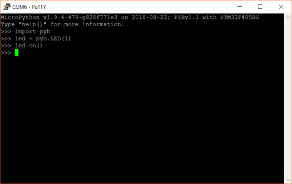
SparkFun SAMD21 Pro RF Hookup Guide

$
0
0

SparkFun SAMD21 Pro RF Hookup Guide a learn.sparkfun.com tutorial

Available online at: http://sfe.io/t810

Introduction

The SparkFun SAMD21 Pro RF is the fated meeting of a SAMD21 and a long-range RFM95W LoRa®-enabled radio. The outcome is a compact, blazing fast microcontroller with excellent point to point data transmission in the 915MHz ISM radio band with LoRa capabilities. In this tutorial we’ll break down the capabilities of the development board, give you a brief introduction to LoRa and get you familiarized with the two Arduino libraries that will get you started with the radio and LoRaWan. If you’re familiar with LoRaWan then skip ahead to the Hardware Overview, otherwise let’s get started with a brief introduction to LoRaWAN.

SparkFun Pro RF - LoRa, 915MHz (SAMD21)

SparkFun Pro RF - LoRa, 915MHz (SAMD21)

WRL-14916
$29.95

Required Materials

To follow along with this tutorial, you will need the following materials. You may not need everything though depending on what you have. Add it to your cart, read through the guide, and adjust the cart as necessary.

Hook-Up Wire - Assortment (Solid Core, 22 AWG)

Hook-Up Wire - Assortment (Solid Core, 22 AWG)

PRT-11367
$16.95
28
USB micro-B Cable - 6 Foot

USB micro-B Cable - 6 Foot

CAB-10215
$4.95
9
Pycom LoRa and Sigfox Antenna Kit - 915MHz

Pycom LoRa and Sigfox Antenna Kit - 915MHz

WRL-14676
$11.95

Single Cell LiPo Batteries

You can power the SAMD21 Pro RF with any of our stocked LiPo Batteries that is above 500mAh.

Lithium Ion Battery - 2Ah

Lithium Ion Battery - 2Ah

PRT-13855
$12.95
3
Lithium Ion Battery - 1Ah

Lithium Ion Battery - 1Ah

PRT-13813
$9.95
6
Lithium Ion Battery - 850mAh

Lithium Ion Battery - 850mAh

PRT-13854
$9.95
2
Lithium Ion Battery - 6Ah

Lithium Ion Battery - 6Ah

PRT-13856
$29.95
5

Tools

Depending on your setup, you may need a soldering iron, solder, and general soldering accessories.

Weller WE1010 Soldering Station

Weller WE1010 Soldering Station

TOL-14734
$129.00
Solder - 1/4lb Spool (0.032") Special Blend

Solder - 1/4lb Spool (0.032") Special Blend

TOL-10243
$24.95
4
Wire Strippers - 20-30AWG

Wire Strippers - 20-30AWG

TOL-14763
$14.95

Suggested Reading

If you’re not familiar with the following topics, or want a more in depth conversation related to the following, please follow the links below.

What is an Arduino?

What is this 'Arduino' thing anyway?

Installing Arduino IDE

A step-by-step guide to installing and testing the Arduino software on Windows, Mac, and Linux.

SAMD21 Mini/Dev Breakout Hookup Guide

An introduction to the Atmel ATSAMD21G18 microprocessor and our Mini and Pro R3 breakout boards. Level up your Arduino-skills with the powerful ARM Cortex M0+ processor.

LoRaWAN with ProRF and The Things Network

Learn how to make a LoRaWAN node for your next long range IoT project and connect it to the internet with The Things Network!

Brief Introduction to LoRaWAN

LoRaWAN stands for Long Range Wide Area Network and describes the technology that allows for devices to send and upload data to the Internet using radio transmission. The technology is a frequency modulation scheme similar in theory but dissimilar to AM or FM which stand for Amplitude Modulation and Frequency Modulation respectively. You remember sine waves right? Amplitude modulation changes the height or amplitude of a wave when adding audio (or data) to it and frequency modulation would change, well, the frequency of a wave when adding audio (or data to it). The modulation scheme for LoRaWAN is more complex to explain but maintains this same theory of changing sine waves when they carry data; you can read more about it in detail below:

Wikipedia: Frequency Shift Keying

This scheme allows for data to be transmitted to the LoRa Network over a specific radio band known as the the Industrial, Scientific, and Medical Band (or ISM band for short). The frequencies of this specific radio band varies from country to country but as an example, the SAMD21 Pro RF will broadcast within the range of 902-928MHz in the Americas and in the range 863-870MHz in Europe. We reference the spectrum of broadcasting frequencies by its' center frequency, 915MHz in the Americas and 868MHz in Europe. Ok, we have a general idea that we broadcast in a band of frequencies using a technology that translates data into radio signals, but how do we get from the SAMD21 Pro RF to the “Internet of Things”?

Broadcasting and uploading requires three things: a Node, a Gateway or Concentrator, and a Network Server. The “Node” in this case is the SAMD21 Pro RF, which will broadcast its information into the void and hope that there is a Gateway or Concentrator nearby to hear it. A Gateway or Concentrator will take the information your node is broadcasting and push it to a Network Server like the The Things Network or Resin.io. Let’s read that in a different way, the Gateway or Concentrator takes the radio waves, demodulates them (i.e. translates them), and puts that information onto the Internet. Neat! Now it’s here on the Network Server that we get to interact with that data. For a more in depth explanation about LoRaWAN, check out this great tutorial.

LoRaWAN with ProRF and The Things Network

July 3, 2018

Learn how to make a LoRaWAN node for your next long range IoT project and connect it to the internet with The Things Network!

Want to setup your own Gateway? Check out the tutorial below!

ESP32 LoRa 1-CH Gateway, LoRaWAN, and the Things Network

August 14, 2018

Using the ESP32 LoRa 1-CH Gateway as a gateway and device, and pushing data to The Things Network.

Hardware Overview

If this is your first time with the SAMD21 then check out our great write up on the hardware specifications of the SAMD21AG MCU and see how it compares with an ATmega328P.

SAMD21 Mini/Dev Breakout Hookup Guide

November 12, 2015

An introduction to the Atmel ATSAMD21G18 microprocessor and our Mini and Pro R3 breakout boards. Level up your Arduino-skills with the powerful ARM Cortex M0+ processor.

Let’s move onto the SAMD21 Pro RF and its hardware features.

Supplying Power

You can power the SAMD21 Pro RF in a number of external 5V sources. At the head of the board, you’ll see a micro-B USB connector and a lithium polymer battery connector that will take any of our stocked LiPo battery options. To safely charge, we recommend using a LiPo with a capacity that is higher than 500mAh. Note the two plated through holes just to the right of the LiPo connector that can be utilized for direct soldering of a LiPo Battery. Next to the switch, you’ll see the pins labeled RAW for a external source of 6V or below.

Highlited image of the Micro-B and Lipo Battery Connector on the topside of the SAMD21 Pro RF

Warning: Powering the SAMD21 Pro RF is easy but the onboard low noise, low dropout voltage regulator can not handle anything above 6V. Please be attentive with how you power it.

Pinout

Logic Levels: Keep in mind that this is a 3.3V system, which interfaces nicely with our Qwiic environment and other 3.3V devices. If you are using the SAMD21 Pro RF with your external 5V devices, we recommend adding a level shifter in between.

Below is a table with every pin on the SparkFun SAMD21 Pro RF and it’s function.

PinDescription
RAWInput Supply Voltage should never exceed 6V
GNDGround on outside thru-holes
3v33.3V OUT
RST3.3V OUT
D2, D3, D4, D5, D9Digital I/O Pins
A0, A1, A2, A3, A4Analog I/O Pins
RX/TXSerial Ports
MOSI/MISO/SCKSPI
ANTAntennae for RFM Module

LEDs

This product carries the full gamut of LEDs we’ve come to expect on SparkFun development boards: STAT LED, CHARGE LED, RX/TX indicators, and a Power LED. The STAT LED is on pin 13, typical on most Arduino boards. The RX and TX LEDs indicate activity on the USB serial port and are also available through the Arduino IDE using the macros PIN_LED_RXL and PIN_LED_TXL as your pin declarations. These LEDs are active-low, so writing the pin HIGH will turn the LED off. The charge LED is controlled by the onboard MCP73831 and lights up when a battery is being charged and turns off when the battery is full.

LEDs on the topside of the SAMD21 Pro RF

RFM95W Radio Module

The RFM95W Radio Module is a powerful but low power module that allows for point to point radio communication. It also has the capability of utilizing the Long Range Wide Area Network (LoRaWan) by closing two LoRaWAN labeled jumpers on the underside.

An image that highlights Radio Module and two LoRaWan Jumpers on the underside of the SAMD21 Pro RF

Antenna

There are two options for an antenna on the SAMD21 Pro RF, a wire and a u.FL connector. The plated through hole and the connector are both labeled by the same ANT silk on the topside of the product.

This is a picture of the topside of the SAMD21 Pro RF witht the Antenna u.FL connector and plated through hole highlighted.

When using the through hole for your antenna, notice the unplated hole just above it. The purpose of this hole is to thread the wire antenna through it so that it takes the stress of daily wear and tear off of the solder joint. Woot!

This is a closeup of the wire antenna soldered into the plated through hole and threaded through the unplated through hole just above it.

How Much Wire Length Do I Need?

We have you covered, here are wire lengths for quarter-wave antennas at 915MHz and 868MHz:

CountryFrequencyLength (inches)Length (mm)
Americas915 MHz3.07" (3 + 1/16")78mm
Europe868 MHz3.38" (3 + 3/8")86mm

u.FL Antenna

Another option is to connect a LoRa Antenna to the u.FL connector.

This is a picture of the SAMD21 Pro RF witha Antenna plugged into the onboard u.FL connector.

Qwiic Connector

On the tail end of the product is a Qwiic connector. If you are not familiar with the system, you can get a full rundown here. In short the Qwiic system is an I2C environment of products that can be rapidly prototyped because we’ve broken out the I2C lines: ground, power, clock, and data, to a four pin JST connector. There’s no need for solder or a soldering iron and our catalog of products with a Qwiic connector are growing rapidly.

This is a picture of a SAMD21 Pro RF where the Qwiic Connector has been highlighted.

Here the SAMD21 ProRF is connected to the Qwiic Triple Axis Accelerometer.

This is a picture of the SAMD21 Pro RF attached to a Qwiic Accelerometer.

Hardware Limitations and Current Capabilities

This topic is mentioned in detail under the SAMD21 Dev/Mini Breakout Hookup Guide but it’s worth restating again here. Depending on the task it’s given, the SAMD21’s core will usually consume between 3-17mA. There should be plenty of juice left from the 600mA 3.3V regulator to power other sensors or components off the board’s 3.3V supply rail.

Each I/O pin can sink up to 10mA and source up to 7mA, with one caveat: each cluster of I/O is limited to sourcing 14mA or sinking 19.5mA. The GPIO clusters are:

ClusterGPIOCluster Supply (Pin)Cluster Ground (Pin)
1SWCLK, SWDIOVDDIN (44)GND (42)
230, 31
(USB_HOST_EN, TX_LED)
VDDIN (44)
VDDIO (36)
GND (42)
GND (35)
3D2, D5, D6, D7, D10, D11, D12, D13, D38
SCL, SDA, MISO, SCK, MOSI
(USB_D-, USB_D+)
VDDIO (36)
VDDIO (17)
GND (35)
GND (18)
4D0, D1, D3, D4VDDIO (17)GND (18)
5A1, A2, A3, A4
D8, D9
VDDANA (6)GNDANA (5)
6A0, A5, AREF
(RX_LED, RTC1, RTC2)
VDDANA (6)GNDANA (5)

If for example, you’re sourcing current to four LEDs tied to pins 0, 1, 3, and 4 (cluster 4), the sum of that current must be less than 14mA (~3.5mA per LED). On a related note, Cluster 3 is mostly occupied by the Radio’s various inputs: interrupt, chip select, and reset as well as the Qwiic Connector.

Setting Up Arduino

Update Arduino! This setup requires at least Arduino version 1.6.4 or later. We've tested it on the latest version – 1.8.5. If you're running an older version of Arduino, consider visiting arduino.cc to get the latest, greatest release.

While the SAMD21 is powerful and completely supported by the Arduino IDE. This following section will list every step required for installing the SparkFun SAMD21 Pro RF into the Arduino IDE.

Install Arduino SAMD Boards

First, we’ll install the SAMD board definitions via the Boards Manager in the Arduino IDE which contains a variety of tools, including low-level ARM Cortex libraries full of generic code, arm-gcc to compile your code, and bossa to upload over the bootloader.

To install the Arduino SAMD board definitions, navigate to your board manager (Tools>Board>Boards Manager…), then find an entry for Arduino SAMD Boards (32-bits ARM Cortex-M0+). Select it, and install the latest version. At the time of this Hookup Guide, version 1.6.19 was used.

Image of the Arduino Boards Manager and the SAMD option contained therein.

Downloading and installing the tools may take a couple minutes – arm-gcc in particular will take the longest, it’s about 250MB unpacked! Once installed. the Installed text will appear next to the SAMD boards list entry. Let’s continue…

Install SparkFun Board Definition

Open your Arduino preferences (File>Preferences). Then find the Additional Board Manager URLs text box, and paste the link listed below in the field encapsulated in the red box:

https://raw.githubusercontent.com/sparkfun/Arduino_Boards/master/IDE_Board_Manager/package_sparkfun_index.json

Board Manager Highlighted

If you’ve done this before with different development boards, then you can add the SparkFun link text to the end of the text, just add a comma between seperate links or click on the small square to the right of the field and add it to the bottom of the list. Now hit OK, and travel back to the Boards Manager menu. You’ll now see a new entry for SparkFun SAMD Boards. If you don’t see it, close the boards manager and open it again. ¯\(ツ)/¯.

Installing the SparkFun SAMD Boards

This installation should be much faster; you’ve already done the heavy lifting in the previous section.

Select the Board and Serial Port

Once the board is installed, you should see a new entry in your Tools>Board list: SparkFun SAMD21 Pro RF.

This is an image of the Tools Dropdown Menu in the Arduino IDE where the Board and Port have been set to the SAMD21 Pro RF.

Finally, select your SAMD21 Pro RF Board’s port. Navigate back up to the Tool>Port menu. The port menu may magically know which of your ports (if you have more than one) are the SAMD21 board. On a Windows machine, the serial port should come in the form of “COM#”. On a Mac or Linux machine, the port will look like “/dev/cu.usbmodem####”.

Point to Point Radio Arduino Examples

Note: This example assumes you are using the latest version of the Arduino IDE on your desktop. If this is your first time using Arduino, please review our tutorial on installing the Arduino IDE. If you have not previously installed an Arduino library, please check out our installation guide.

For this example we’ll be utilizing the Radio Head Library to utilize the RFM96W Radio Module. You can download the Radio Head library from its' GitHub repo, or click the link below. While you’re clicking on buttons, all of the Arduino example code can be downloaded by downloading it from the SAMD21 Pro RF Arduino Examples GitHub repo or clicking the second button below.

Download RadioHead Arduino Library (ZIP)

Download SAMD21 Pro RF Arduino Examples (ZIP)

One last thing before we go any farther. The SAMD21 is a highly versatile chip and we’ve taken advantage of that fact by creating two seperate UART lines, one that interfaces with the computer through the micro-B and another one broken out on the RX/TX header on the side of the board. To communicate to the Arduino IDE’s serial monitor, we’ll be using the statement SerialUSB, rather than the normal Serial that you might be used to. Are they different? Nope! Just different nomenclature for different UART lines.

Point to Point Radio Arduino Examples

Radio Server

Note: For the following two examples to work you'll need one radio module to send your message and another to hear and respond. This example uses two SAMD21 Pro RF's communicating to each other.

Assuming that the Arduino library you downloaded and installed is working correctly, let’s move onto our first example. This example and the following example build off of the sample code provided by the RadioHead library but has been tailored for the SAMD21 Pro RF.

language:c
#include <SPI.h>

//Radio Head Library: 
#include <RH_RF95.h>

// We need to provide the RFM95 module's chip select and interrupt pins to the 
// rf95 instance below.On the SparkFun ProRF those pins are 12 and 6 respectively.
RH_RF95 rf95(12, 6);

int LED = 13; //Status LED on pin 13

int packetCounter = 0; //Counts the number of packets sent
long timeSinceLastPacket = 0; //Tracks the time stamp of last packet received
// The broadcast frequency is set to 921.2, but the SADM21 ProRf operates
// anywhere in the range of 902-928MHz in the Americas.
// Europe operates in the frequencies 863-870, center frequency at 
// 868MHz.This works but it is unknown how well the radio configures to this frequency:
//float frequency = 864.1;
float frequency = 921.2;

void setup()
{
  pinMode(LED, OUTPUT);

  SerialUSB.begin(9600);
  // It may be difficult to read serial messages on startup. The following
  // line will wait for serial to be ready before continuing. Comment out if not needed.
  while(!SerialUSB);
  SerialUSB.println("RFM Server!");

  //Initialize the Radio. 
  if (rf95.init() == false){
    SerialUSB.println("Radio Init Failed - Freezing");
    while (1);
  }
  else{
  // An LED indicator to let us know radio initialization has completed.
    SerialUSB.println("Receiver up!");
    digitalWrite(LED, HIGH);
    delay(500);
    digitalWrite(LED, LOW);
    delay(500);
  }

  rf95.setFrequency(frequency); 

  // Transmitter power can range from 14-20dbm.
  rf95.setTxPower(14, true);
}

void loop()
{
  if (rf95.available()){
    // Should be a message for us now
    uint8_t buf[RH_RF95_MAX_MESSAGE_LEN];
    uint8_t len = sizeof(buf);

    if (rf95.recv(buf, &len)){
      digitalWrite(LED, HIGH); //Turn on status LED
      timeSinceLastPacket = millis(); //Timestamp this packet

      SerialUSB.print("Got message: ");
      SerialUSB.print((char*)buf);
      //SerialUSB.print(" RSSI: ");
      //SerialUSB.print(rf95.lastRssi(), DEC);
      SerialUSB.println();

      // Send a reply
      uint8_t toSend[] = "Hello Back!"; 
      rf95.send(toSend, sizeof(toSend));
      rf95.waitPacketSent();
      SerialUSB.println("Sent a reply");
      digitalWrite(LED, LOW); //Turn off status LED

    }
    else
      SerialUSB.println("Recieve failed");
  }
  //Turn off status LED if we haven't received a packet after 1s
  if(millis() - timeSinceLastPacket > 1000){
    digitalWrite(LED, LOW); //Turn off status LED
    timeSinceLastPacket = millis(); //Don't write LED but every 1s
  }
}

Radio Client

language:c
/*
  Both the TX and RX ProRF boards will need a wire antenna. We recommend a 3" piece of wire.
  This example is a modified version of the example provided by the Radio Head
  Library which can be found here:
  www.github.com/PaulStoffregen/RadioHeadd
*/

#include <SPI.h>

//Radio Head Library:
#include <RH_RF95.h> 

// We need to provide the RFM95 module's chip select and interrupt pins to the
// rf95 instance below.On the SparkFun ProRF those pins are 12 and 6 respectively.
RH_RF95 rf95(12, 6);

int LED = 13; //Status LED is on pin 13

int packetCounter = 0; //Counts the number of packets sent
long timeSinceLastPacket = 0; //Tracks the time stamp of last packet received

// The broadcast frequency is set to 921.2, but the SADM21 ProRf operates
// anywhere in the range of 902-928MHz in the Americas.
// Europe operates in the frequencies 863-870, center frequency at 868MHz.
// This works but it is unknown how well the radio configures to this frequency:
//float frequency = 864.1; 
float frequency = 921.2; //Broadcast frequency

void setup()
{
  pinMode(LED, OUTPUT);

  SerialUSB.begin(9600);
  // It may be difficult to read serial messages on startup. The following line
  // will wait for serial to be ready before continuing. Comment out if not needed.
  while(!SerialUSB); 
  SerialUSB.println("RFM Client!"); 

  //Initialize the Radio.
  if (rf95.init() == false){
    SerialUSB.println("Radio Init Failed - Freezing");
    while (1);
  }
  else{
    //An LED inidicator to let us know radio initialization has completed. 
    SerialUSB.println("Transmitter up!"); 
    digitalWrite(LED, HIGH);
    delay(500);
    digitalWrite(LED, LOW);
    delay(500);
  }

  // Set frequency
  rf95.setFrequency(frequency);

   // Transmitter power can range from 14-20dbm.
   rf95.setTxPower(14, true);
}


void loop()
{
  SerialUSB.println("Sending message");

  //Send a message to the other radio
  uint8_t toSend[] = "Hi there!";
  //sprintf(toSend, "Hi, my counter is: %d", packetCounter++);
  rf95.send(toSend, sizeof(toSend));
  rf95.waitPacketSent();

  // Now wait for a reply
  byte buf[RH_RF95_MAX_MESSAGE_LEN];
  byte len = sizeof(buf);

  if (rf95.waitAvailableTimeout(2000)) {
    // Should be a reply message for us now
    if (rf95.recv(buf, &len)) {
      SerialUSB.print("Got reply: ");
      SerialUSB.println((char*)buf);
      //SerialUSB.print(" RSSI: ");
      //SerialUSB.print(rf95.lastRssi(), DEC);
    }
    else {
      SerialUSB.println("Receive failed");
    }
  }
  else {
    SerialUSB.println("No reply, is the receiver running?");
  }
  delay(500);
}

The “Server” and “Client” nomenclature may be a bit misleading. It might be more accurate to say “call” and “call-back”. None the less, there are a few notable changes made from the original examples.

  • Chip Select and Interupt Pins
    • RH_RF95 rf95(12, 6)– Pin 12 and pin 6 are the assigned pins that run to the RM95 Radio Module’s chip select and interrupt pins.
  • SerialUSB or Serial?
    • while(!SerialUSB)– When the SAMD21 Pro RF starts up, it’s not always a smooth transition and messages meant for the serial monitor will get missed. This line will hold your code hostage until you open the serial monitor at which point it will continue on. We have two UART lines for this microcontroller, the one that communicates with the serial monitor is called using the keyword SerialUSB.
  • Frequency Select
    • rf95.setFrequency(frequency)– The default frequency is kind of random, 921.2 but it falls within the American ISM band: 902-928MHz. If you’re in Europe, that band is 863-870MHz. You’ll find the variable “frequency” is set a little higher up in the code.

After you upload the code to two SAMD21 Pro RF’s, open a serial monitor set at 9600. You should see the following readout in the serial monitors!

This is an image of two serial monitor windows open, reading "Hello" and "Hello Back!".

Click the image for a closer look at the output.

LoRaWAN Arduino Example

The Internet of Things “Hello World” - Node Example

For this example, we’ll be setting up the SAMD21 Pro RF as a node using a library written by Matthijs Kooijman which is a modified version of “IBM’s LMIC (LoraMAC-in-C)” library. You can download it through the Arduino Library Manager under “LMIC-Arduino”. You can also download and manually install it from the GitHub Repository, or click the button below to manually install it from there.

Arduino LMIC Library Download (ZIP)

This example requires that you have an account with The Things Network and a nearby gateway. Read the brief introduction above to learn about nodes, gateways, and network servers. First, we’ll need an account at The Things Network which will provide us our network server to manage, graph, and/or look at our data in the case of our “Hello World” example below. On the front page of the website there’s a map that shows active gateways in your area. If you don’t have a gateway nearby, you can set one up using SparkFun’s ESP32 1-Ch Gateway, using this excellent set up guide here. This is the gateway that I chose to use for this example.

Registering Your Node

This rest of this example assumes that you have an account with The Things Network. It's free and only requires an email address!

Before you can upload with the SAMD21 Pro RF, you’ll need to sign up for an account on their website. Registering with their website is free, and allows the network to generate the necessary keys which identify your projects and nodes.

Screenshot of the console page on the Things Network Web Page.

You’ll notice that there’s no option to just add a node, that’s because The Things Network needs to know what application to associate with your device. Therefore, you’ll need to start by creating an application. Clicking on the Applications button will take you to a page that looks like this:

Screenshot of the Applications menu with a message in the center reading "You do not have any applications." and a link below it that reads "Get started by adding one!", there is a small link in the top right-hand corner of the menu that reads "add application" with a small green circle-with-a-plus-sign icon next to it.

This would usually be a list of all your applications, but The Things Network automatically recognizes that you don’t have any applications yet and suggests that you add one. You can add an application either by clicking that link or clicking on “add application” in the upper right corner. Both of those links will take you to this page:

Screenshot of the Add Application menu showing the various form fields described below.

Give your application an Application ID (identifier); this is the name that The Things Network will use to distinguish it from the other applications. It can only contain lowercase letters, numbers, and dashes. The description field is for humans, so take a moment to write a sentence about what your app does. In this case, I’ve just written that it’s an example application. The EUI will be issued by the network, so there’s no need to type anything there. Finally, select the handler that you want your application to be registered to. Essentially, these are instances of the network server in different physical locations around the world. All applications will talk to all network servers, but to minimize latency, it’s best to select the handler closest to your gateway. SparkFun is located in Colorado, so I chose “ttn-handler-us-west,” which I assume is in California somewhere. Click the Add Application button and you’ll be taken to your freshly generated application console.

Screenshot of the Devices menu with a message in the center reading "0 registered devices", there is a small link in the top right-hand corner of the menu that reads "register device" with a small green circle-with-a-plus-sign icon next to it, as well as a link that reads "manage devices" with a small gear icon next to it.

Now that you’ve created an application, you can register a device to it. Scroll down to the Devices section of the application page and you will see your current device count (which is none) as well as options to register a device and to manage devices. Click on register device.

Screenshot of the Register Device menu showing the various form fields described below.

This form is pretty similar to the Register an Application page, but you have a little less to do. Give your device a Device ID, the same rules apply as did with the Application ID. Then click the little crossed arrows beside the Device EUI field, this lets TTN know that you want them to generate an EUI for you. Now just click on the Register button at the bottom of the form.

Screenshot of the Device Overview menu showing the various form fields described below.

And now you’ve been taken to your brand new device console. Under the section labeled Device Overview you’ll notice the Application ID and Device ID that you set earlier. Under Activation Method it will likely say “OTAA,” which stands for Over The Air Activation. This is a secure, transportable method of activating LoRaWAN devices, whereby the device uses a known application key to request new session keys whenever it wants to join the network. This is the preferred method for activating a production device, but for prototyping it’s usually easier to hard code the session keys into your device. In order to do this, we’ll need to set the activation method to “ABP” or Activation By Personalization. To do this, click on the Settings tab in the upper right-hand corner of the device page and you’ll be taken to the device settings menu. Partway down the page you should find an option to change the activation method.

Screenshot illustrating the Activation Method selection switch

Click on “ABP,” and then save your settings. When you return to the Overview page, you should now see some extra fields in the Device Overview:

Screenshot of the Device Overview menu showing the new form fields added.

We’ll need these keys to program your SAMD21 Pro RF so leave this page up on your browser and let’s open up the Arduino IDE. It’s time to program the node!

Programming the SAMD21 Pro RF

This modified example takes directly from the example code provided by the library with a two changes: the function calls to “Serial” have been replaced with “SerialUSB” and changes to the pin mapping that is consistent with the SAMD21 Pro RF. Before we look at the code you’ll first need to modify the config.h file that came with the LMIC Arduino Library.

Find your Arduino libraries folder and navigate to …IBM_LMIC_framework/src/lmic/. You should find a file called config.h. Open it in any text editor and find the lines where CFG_us915 is defined. It should look like this:

language:c
//#define CFG_eu868 1
#define CFG_us915 1
// This is the SX1272/SX1273 radio, which is also used on the HopeRF
// RFM92 boards.
//#define CFG_sx1272_radio 1
// This is the SX1276/SX1277/SX1278/SX1279 radio, which is also used on
// the HopeRF RFM95 boards.
#define CFG_sx1276_radio 1

Since we’re using the 915MHz radio module in the US, you need to make sure that the line #define CFG_us915 1 is not commented out and that the line #define CFG_eu868 1 is, by prepending // as shown above. Same goes for the radio type, we want #define CFG_sx1276_radio 1 and not #define CFG_sx1272_radio 1. Notice how the first “#define” contains “eu868”, short for Europe and its center frequency. The line we un-commented contains “us915” which is undoubtedly for United States, with its center frequency at 915. With those changes made, save the config.h file and return to the Arduino IDE.

In order to make it work with your application you’ll need to copy in some keys from the Device Overview page on your TTN Console, so flip back to the browser tab with the Device Overview page loaded up.

You’ll notice that, by default, the Network Session Key and App Session Key fields are obscured for security reasons. You can click the eye icon to show the code before copying it. Also, it will be easier to copy this into the example code if you click the <> button to show the codes in “C style”, a bunch of HEX designated numbers.

You will need to copy three separate numbers into your example code from this page:

  • Network Session Key =(i.e. NWKSKEY[])
  • App Session Key (i.e. PROGMEM APPSKEY[])
  • Device Address (i.e.DEVADDR)

Here’s a diagram explaining which field on this page corresponds to which constant in the example code:

Screenshot of the Device Address, Network Session Key, and App Session Key fields from the Device Overview page with red arrows and text pointing out several labels and icons. An icon with a stylized eye on it un-obscures the Key fields which are obscured by default for security reasons. An icon with angle brackets on it expands the Key fields into "c style," adding hex prefixes to each value, separating them with commas, and enclosing them in curly brackets. The Device Address field is labeled DEVADDR. The Network Session Key field is labeled NWKSKEY. The App Session Key field is labeled "APPSKEY".

Click the image for a closer look.

Notice the three lines at the top of the code that say “Network Session Key Here”, “Application Key Here”, and “Device Address here”. These lines can be replaced by the keys from the website.

language:c
#include <lmic.h>
#include <hal/hal.h>
#include <SPI.h>

// LoRaWAN NwkSKey, network session key
static const PROGMEM u1_t NWKSKEY[16] ={ NETWORK SESSION KEY HERE };  

// LoRaWAN AppSKey, application session key
static const u1_t PROGMEM APPSKEY[16] = { APPLICATION KEY HERE };

// LoRaWAN end-device address (DevAddr)
static const u4_t DEVADDR =  DEVICE ADDRESS HERE;

// These callbacks are only used in over-the-air activation, so they are
// left empty here (we cannot leave them out completely unless
// DISABLE_JOIN is set in config.h, otherwise the linker will complain).
// Well alright......
void os_getArtEui (u1_t* buf) { }
void os_getDevEui (u1_t* buf) { }
void os_getDevKey (u1_t* buf) { }

static uint8_t mydata[] = "Hello, world!";
static osjob_t sendjob;

// Schedule TX every this many seconds (might become longer due to duty
// cycle limitations).
const unsigned TX_INTERVAL = 5;

// Pin mapping
const lmic_pinmap lmic_pins = {
    .nss = 12,//RFM Chip Select
    .rxtx = LMIC_UNUSED_PIN,
    .rst = 7,//RFM Reset
    .dio = {6, 10, 11}, //RFM Interrupt, RFM LoRa pin, RFM LoRa pin
};

void onEvent (ev_t ev) {
    SerialUSB.print(os_getTime());
    SerialUSB.print(": ");
    switch(ev) {
        case EV_SCAN_TIMEOUT:
            SerialUSB.println(F("EV_SCAN_TIMEOUT"));
            break;
        case EV_BEACON_FOUND:
            SerialUSB.println(F("EV_BEACON_FOUND"));
            break;
        case EV_BEACON_MISSED:
            SerialUSB.println(F("EV_BEACON_MISSED"));
            break;
        case EV_BEACON_TRACKED:
            SerialUSB.println(F("EV_BEACON_TRACKED"));
            break;
        case EV_JOINING:
            SerialUSB.println(F("EV_JOINING"));
            break;
        case EV_JOINED:
            SerialUSB.println(F("EV_JOINED"));
            break;
        case EV_RFU1:
            SerialUSB.println(F("EV_RFU1"));
            break;
        case EV_JOIN_FAILED:
            SerialUSB.println(F("EV_JOIN_FAILED"));
            break;
        case EV_REJOIN_FAILED:
            SerialUSB.println(F("EV_REJOIN_FAILED"));
            break;
        case EV_TXCOMPLETE:
            SerialUSB.println(F("EV_TXCOMPLETE (includes waiting for RX windows)"));
            if (LMIC.txrxFlags & TXRX_ACK)
              SerialUSB.println(F("Received ack"));
            if (LMIC.dataLen) {
              SerialUSB.println(F("Received "));
              SerialUSB.println(LMIC.dataLen);
              SerialUSB.println(F(" bytes of payload"));
            }
            // Schedule next transmission
            os_setTimedCallback(&sendjob, os_getTime()+sec2osticks(TX_INTERVAL), do_send);
            break;
        case EV_LOST_TSYNC:
            SerialUSB.println(F("EV_LOST_TSYNC"));
            break;
        case EV_RESET:
            SerialUSB.println(F("EV_RESET"));
            break;
        case EV_RXCOMPLETE:
            // data received in ping slot
            SerialUSB.println(F("EV_RXCOMPLETE"));
            break;
        case EV_LINK_DEAD:
            SerialUSB.println(F("EV_LINK_DEAD"));
            break;
        case EV_LINK_ALIVE:
            SerialUSB.println(F("EV_LINK_ALIVE"));
            break;
         default:
            SerialUSB.println(F("Unknown event"));
            break;
    }
}

void do_send(osjob_t* j){
    // Check if there is not a current TX/RX job running
    if (LMIC.opmode & OP_TXRXPEND) {
        SerialUSB.println(F("OP_TXRXPEND, not sending"));
    }
    else{
        // Prepare upstream data transmission at the next possible time.
        LMIC_setTxData2(1, mydata, sizeof(mydata)-1, 0);
        SerialUSB.println(F("Packet queued"));
    // Next TX is scheduled after TX_COMPLETE event.
    }
}

void setup() {
    SerialUSB.begin(115200);
    // Serial communication on startup is not consistent on the SAMD21. The
    // following line waits for the serial monitor to be opened before
    // continuing. Uncomment if not needed.
    while(!SerialUSB); 
    SerialUSB.println("Starting");

    // LMIC init
    os_init();
    // Reset the MAC state. Session and pending data transfers will be discarded.
    LMIC_reset();

    // Set static session parameters. Instead of dynamically establishing a session
    // by joining the network, precomputed session parameters are be provided.
    #ifdef PROGMEM
    // On AVR, these values are stored in flash and only copied to RAM
    // once. Copy them to a temporary buffer here, LMIC_setSession will
    // copy them into a buffer of its own again.
    uint8_t appskey[sizeof(APPSKEY)];
    uint8_t nwkskey[sizeof(NWKSKEY)];
    memcpy_P(appskey, APPSKEY, sizeof(APPSKEY));
    memcpy_P(nwkskey, NWKSKEY, sizeof(NWKSKEY));
    LMIC_setSession (0x1, DEVADDR, nwkskey, appskey);
    #else
    // If not running an AVR with PROGMEM, just use the arrays directly
    LMIC_setSession (0x1, DEVADDR, NWKSKEY, APPSKEY);
    #endif

    #if defined(CFG_us915)
    // NA-US channels 0-71 are configured automatically
    // but only one group of 8 should (a subband) should be active
    // TTN recommends the second sub band, 1 in a zero based count.
    // https://github.com/TheThingsNetwork/gateway-conf/blob/master/US-global_conf.json
    LMIC_selectSubBand(1);
    #endif

    // Disable link check validation
    LMIC_setLinkCheckMode(0);

    // TTN uses SF9 for its RX2 window.
    LMIC.dn2Dr = DR_SF9;

    // Set data rate and transmit power for uplink (note: txpow seems to be ignored by the library)
    LMIC_setDrTxpow(DR_SF7,14);

    // Start job
    do_send(&sendjob);
}

void loop() {
    os_runloop_once();
}

Below are a few modifications to the original code that have been made to tailor it to the SAMD21 Pro RF.

  • SerialUSB
    • while(!SerialUSB)– When the SAMD21 Pro RF starts up, it’s not always a smooth transition and messages meant for the serial monitor will get missed. This line will hold your code hostage until you open the serial monitor at which point it will continue on. The SAMD21 Pro RF has two UART lines, SerialUSB references the one that communicates with the computer via the Micro-B connector.

We’ve also had to change the pin mappings to be consitent with the reset, chip select, interrupt, and LoRaWAN lines of the RFM95W module.

language:c   
const lmic_pinmap lmic_pins = {
    .nss = 12,//RFM Chip Select
    .rxtx = LMIC_UNUSED_PIN,
    .rst = 7,//RFM Reset
    .dio = {6, 10, 11}, //RFM Interrupt, RFM LoRa pin, RFM LoRa pin
};

Close the LoRaWAN Jumpers

One last thing. On the underside of the SAMD21 Pro RF there are two jumpers labeled LoRaWAN. Closing these jumpers will tell the module that we’re broadcasting in the modulation scheme unique to LoRaWAN.

A picture of the underside of the SAMD21 Pro RF where the two LoRaWAN jumpers have been closed with solder.

Upload the code and let’s go back to the website and see what it looks like!

Decode Your Data

You may have noticed in the Application Data window that your payload is shown in raw bytes. In order to see “Hello, World!” encoded in ASCII, the way you sent it, you’ll need to decode the payload. The Things Network includes tools for doing this right in the console! Navigate to the Application Overview page for your application and click on the Payload Formats tab. This menu allows you to write functions which will be applied to all incoming packets for this application.

Screenshot of the Payload Formats page, showing a field labeled "decoder" where code can be typed. Some example code is in the field by default. It doesn't appear to return anything.

So let’s write our own decoder. We need to take the raw byte data and return a string that contains all of the characters corresponding to each byte. Take a look at this solution and then we’ll walk through it:

language:js
function Decoder(bytes, port) {

return {
    ASCII: String.fromCharCode.apply(null, bytes)
};

}

Decoder is a Javascript function that The Things Network has already set up for us. It takes two arguments called bytes, an array containing our payload, and port, the LoRaWAN™ “FPort” of the packet. FPort identifies the end application or service that the packet is intended for. Port 0 is reserved for MAC messages. We don’t need to know anything about the port number for our example.

We can return any value that we want from the Decoder function and it will appear alongside our payload in the Application Data window. In the example above, I’ve created a new property called “ASCII” which is equal to String.fromCharCode.apply(null, bytes). To break this down a little more, we’re returning a new String object called “ASCII,” and we’re using the Javascript apply() method to call fromCharCode() with the argument bytes and stuff the result into our new String. The fromCharCode() method simply steps through each byte in the array bytes (which, remember, contains our payload) and returns the ASCII character represented by that character code.

After copying the above code into your decoder function, scroll down and click the save payload functions button. Now return to the Application Data window and you should see that all packets received after the decoder function was changed now have a new property:

Another screenshot of the Application Data page, this time showing several packets received. The latest packet at the top of the list has a new field beside payload labeled "ASCII" with the value "Hello, world!"

Our packet has been decoded! Neat!

Using the Data

Okay, so now you have data coming into your TTN application but what do you do with it? Well, you have a few options:

APIs

The most basic endpoints for interacting with The Things Network programmatically are the TTN Handler APIs or “application programming interfaces”. There are two APIs, the Data API and the Application Manager API. The Data API allows you to send and receive messages, making it the most useful for most applications. You can interact with this API using the MQTT protocol. The Application Manager API is available directly through HTTP and lets you manage applications, gateways, and devices. It’s much more powerful than the Data API and is mostly intended to allow endpoint applications to perform device management.

SDKs

The Things Network has also created several Software Developer Kits (SDKs) which allow you to program your application without having to interact directly with the low level APIs. SDKs are available for several popular languages.

Integrations

Finally, the easiest way to access your data and put it to work is with The Things Network’s various platform integrations. Integrations allow you to pass your application data directly to another platform such as AWS IoT, Cayenne, EVRYTHNG, or IFTTT. From there, you can use those platforms to interact with your data.

Resources and Going Further

The SAMD21 Pro RF is a powerful microcontroller with LoRaWAN capabilities. To best take advantage of it, plug in a LiPo battery and a Qwiic enabled sensor. Perhaps you don’t have a gateway nearby, or have found that they can be quite expensive? Look no further than our ESP32 LoRa 1 Ch Gateway with its excellent hookup guide.

Need some inspiration for your next project? Check out some of these related tutorials:

SparkFun Blocks for Intel® Edison - OLED Block

A quick overview of the features of the OLED Block for the Edison.

Experiment Guide for the Johnny-Five Inventor's Kit

Use the Tessel 2 and the Johnny Five Inventors kit to explore the world of JavaScript enabled hardware through 14 awesome experiments!

How to Use Remote Desktop on the Raspberry Pi with VNC

Use RealVNC to connect to your Raspberry Pi to control the graphical desktop remotely across the network.

LoRaWAN with ProRF and The Things Network

Learn how to make a LoRaWAN node for your next long range IoT project and connect it to the internet with The Things Network!

learn.sparkfun.com | CC BY-SA 3.0 | SparkFun Electronics | Niwot, Colorado

Flashlight Kit

$
0
0

Flashlight Kit a learn.sparkfun.com tutorial

Available online at: http://sfe.io/t811

Introduction

The Flashlight Soldering Kit is a basic soldering kit designed to help teach the basics of through hole soldering and circuit design. This tutorial will go over the basics of a circuit, how to solder, and show you how to build your own flashlight.

SparkFun Basic Flashlight Soldering Kit

SparkFun Basic Flashlight Soldering Kit

KIT-14877
$4.95

Required Tools

To build this you will need a few basic tools such as a soldering iron, solder, and snippers. If you have never soldered before and are looking for a basic setup, the Beginners Tool Kit is a great place to start.

SparkFun Beginner Tool Kit

SparkFun Beginner Tool Kit

TOL-14681
$49.95
Soldering Iron - 60W (Adjustable Temperature)

Soldering Iron - 60W (Adjustable Temperature)

TOL-14456
$12.95
6
Solder Lead Free - 15-gram Tube

Solder Lead Free - 15-gram Tube

TOL-09163
$3.50
2
Diagonal Cutters

Diagonal Cutters

TOL-08794
$1.95
2

Suggested Reading

Here are a few basic tutorials on some of the concepts that we will cover. There are also links throughout the tutorial to give you more information on a topic if you are confused or just interested in learning more.

How to Solder: Through-Hole Soldering

This tutorial covers everything you need to know about through-hole soldering.

Resistors

A tutorial on all things resistors. What is a resistor, how do they behave in parallel/series, decoding the resistor color codes, and resistor applications.

Light-Emitting Diodes (LEDs)

Learn the basics about LEDs as well as some more advanced topics to help you calculate requirements for projects containing many LEDs.

Polarity

An introduction to polarity in electronic components. Discover what polarity is, which parts have it, and how to identify it.

Hardware Overview

Contents

Inside your kit you’ll find a few parts. There should be a PCB, a small coin cell battery, a battery holder, an LED, a resistor, and a switch. We’ll get into what each of these components looks like and what they do in the next section. Missing any parts? Sometimes one of those tiny little components can get misplaced. If you’re missing any parts contact our customer service team, and we’ll get you those missing parts in a jiffy.

Picture of all components in the kit

Before we get started lets take a basic look at the PCB. On the front you can see markings and outlines for the 4 different components as well as some labels. You can also see the traces on the board and how they go from one component to another making a complete circle. On the back you see that the holes have a copper ring around them so you can solder them. You’ll also see a schematic of the circuit showing all 4 components (with each labeled). We’ll get into what each component does in a minute.

Front of PCBBack of PCB
Front of the BoardBack of the Board

Flashlight Circuit

The Circuit

So, what does our circuit do? A completed circuit is a path where electrons can flow. Consider the battery our source of electrons. Current is how we measure the flow of those electrons. Starting with the positive end of the battery, you can see the path it takes along the left side of our PCB up to the resistor. Batteries are basically our power house that stores power and outputs that power in terms of current (how fast the electrons are moving) and the voltage (the amount of pressure pushing those electrons through the circuit).

Photo of battery holderBattery symbol
Battery HolderSchematic Notation for Battery

The Resistor

The resistor is like a tube that restricts the amount of current that can get through. This resistor minimizes the current that gets to your LED so we don’t give the LED too much current and destroy it. If you are curious how this works you can check out our LED tutorial to see how to properly size a resistor. If you look closely at your resistor you’ll notice some color bands. In this kit we use a 5 band resistor (brown, black, black, gold, brown); this is a 10 Ohm resistor with a 1% tolerance. Resistors are not directional, meaning they can be used in the circuit in either a forwards configuration (brown, black, black, gold, brown) or a backwards configuration (brown, gold, black, black, brown) and still function correctly.

Photo of ResistorsResistor symbol
ResistorsSchematic Notation for Resistor

The LED

Next we have the LED. LED stands for light emitting diode. A diode is 2 pieces of semiconductor placed together to allow current to only flow in one direction. This is one of the reasons your LED is polarized (meaning it matters which way you hook it up). The current can only flow from the positive side (anode) to the negative side (cathode). In this case we are using a light emitting diode, which does exactly what it sounds like. It is a diode that emits light which is very convenient for a flashlight. Using different substances in the diode allow for different colors; for our flashlight we chose a white LED.

Photo of LEDLED symbol with Anode and Cathode labeled
LEDSchematic Notation for LED

The Switch

Last we have our switch. A switch is actually a mechanical part, meaning you have to physically move the switch Physically moving the switch will connect the negative pin from your LED to the negative pin of your battery, thus completing the circuit. Flip the switch the other way and the switch physically disconnects those 2 components.

Photo of SwitchSwitch symbol
SwitchSchematic Notation for Switch

The Schematic

Once you put everything together, our electrons will flow (when the switch is in the On position) and our flashlight will turn on. Here is a picture of the completed board and the full schematic (also found on the back of the PCB).

Photo of Assembled KitSchematic of Flashlight Kit
Completed FlashlightSchematic Notation for Completed Circuit

How to Solder

Soldering is basically melting metal. Solder is a specially formulated metal with a relatively low melting point. For example the melting point of solder is typically about 370F(188C) to 428F(220C) where as the melting point of copper is 1984 F (1085C). With a soldering iron we can melt the solder in order to connect two pieces of metal. This connection is both mechanical (physically holds the parts together) and electrical (allows electricity to flow between them). If you look at the front of your PCB, you’ll can see the copper traces that are run just under the surface and are exposed in the holes we are going to solder to.

A Tip About Tips

So, how do you solder? The goal is to heat the metal pads and the components and then let them melt the solder. Do not try to melt the solder and then wipe it where you want it as that will both cause bad joints and get pretty messy. Soldering irons come with many different tips. While finer points may work better for finer work, fatter tips hold heat better and therefore can be used more quickly and efficiently than finer points. Ultimately it is a personal choice, but the tip your iron comes with is a good place to start.

Position is Everything

When soldering you’ll want to avoid trying to heat things with the point of the iron. Use the side near the tip for the most effective heat transfer. Place the iron next to the joint between the board and the component, wait about 1 second and then feed about 1/2in (about 1cm) of solder into the joint. It should melt immediately and make a nice shiny mountain of solder. Once you have enough solder remove the solder and then the iron. If you remove the iron first your roll of solder will be stuck to your joint. If this happens don’t worry, just heat up the joint, remove the solder (and then the iron) and you are good to go. If it doesn’t melt right away you may need to wait a bit longer, check your iron placement, clean your tip, or increase the temperature of your iron.

Check out the Vimeo version here.

Keep it Clean

Don’t forget to clean your tip periodically! I usually try to do this every time I put the iron back in the stand. No matter what you do you, you are likely to end up with burnt on gunk on the end of your iron. A lot of that will be flux (a substance used to make the solder flow better that is actually part of a lot of solders you buy), or old burnt solder. Most soldering iron stands will have a spot for a sponge to wipe your tip on. You will need to use either a brass sponge or a regular sponge that is wet to wipe off your tip. For more soldering tips and info check out our soldering tutorial.

Graphic on soldering best practices

Click for a larger image.

Assembly Guide

We are going to start with the smallest components first and add parts in as they get larger. This makes it easier to get your components to stay put when you are soldering them in.

Attaching the Resistor

First we’ll add the resistor. Bend the ends down at a right angle so that it looks like a ‘U’. Personally I like to just bend them over my finger, but depending on your finger size this may or may not work well. We are then going to insert each end into the board in the spot labeled “Resistor”. Turn the board over and pull the leads through. Your resistor should be sitting pretty flush to the PCB. It doesn’t have to be perfect, but the closer it is, the neater it will look. Now you can go ahead and bend the legs over a bit to help hold everything in place. Then solder the 2 joints (see above for correct solder methods).

Photo of resistor being bent overPhoto of resistor being soldered to the board
Shaping the ResistorSolder Points for Resistor Legs

Attaching the Battery Holder

Next we are going to solder on the battery holder. Make sure you put it in the right way! The board will have an outline on it showing which way it goes. Solder the 2 pins on the bottom side of the board. The battery holder should be fairly flush to the board. While it doesn’t need to be perfectly flush, it needs to be flush enough that both feet go through the board and can be soldered. If you solder in the first pin and find that it isn’t sitting flush don’t worry. Put pressure on the board with one hand and heat up the joint with the other hand. Once the solder melts the part should snap into place.

Attaching the Switch

Next is the switch. Insert the switch (either direction is fine) and flip the board over Solder the 3 switch pins into place. Again the switch should be fairly flush to the board. Look at that, you are becoming a pro at this!

Photo of switch and battery holder in boardPhoto of switch and battery holder soldered
Switch Placement on the Front of the BoardSolder Points for the Switch on the Back of the Board

Attaching the LED

The final solder step is the LED. LEDs are polarized, meaning the direction you insert the LED matters. If you take a look at your LED you’ll notice one leg is longer than the other. Insert the LED with the long leg on the side labeled “Long Leg”. Insert the LED almost to the board and bend it over so it lays in the slot on the top of the PCB. It doesn’t have to be exact, but this will allow your flashlight to shine forward instead of straight up and in your eyes. Then you can bend the legs back on the back of the PCB to help hold it in place and solder the legs.

Photo of LED showing one leg longer than the otherPhoto of LED being folded over on board
LED - Note One Leg is Longer! Placement and Shaping of LED

Clean Up

Next is a bit of clean up. Clip off all your extra leads on the back side of the board; you don’t want things making connections they shouldn’t and the switch pins can poke you if you are not careful. Get a good pair of cutters and snip those leads off! The last step is to put your battery in, make sure the switch is in the “On” position, and let your light shine!

Photo of resistor being bent overPhoto of resistor being bent over
Front of the Finished BoardBack of the Finished Board

Troubleshooting

Flashlight Not Turning On

  • Make sure you turned the switch to the On position
  • Make sure you inserted a new CR2032 battery (and that it is in + side up)
  • Double check all solder joints to make sure they have a good connection
  • Make sure you soldered your LED in the correct way
  • Make sure you clipped your leads so you don’t have any shorts

Flashlight Flickering

  • Make sure all components are soldered in place well
  • Make sure battery is in securely
  • Make sure switch is pushed all the way up
  • Make sure there are no “extra” connections - the leads on the back side of the board should be cleanly clipped.

Flashlight Is Dim

  • Make sure resistor value is 10Ω (brown-black-black-gold-brown)
  • Replace battery as needed

Resources and Going Further

Now that your flashlight is lighting everything up, where do you go from here? Check out some of our different tools as well as some additional kits you can solder together. Also, check out some of our other soldering tutorials, or just start building your own projects.

Resources for This Kit:

Soldering Kits

SparkFun Simon Says - Through-Hole Soldering Kit

SparkFun Simon Says - Through-Hole Soldering Kit

KIT-10547
$24.95
34
SparkFun WeevilEye - Beginner Soldering Kit

SparkFun WeevilEye - Beginner Soldering Kit

KIT-10723
$9.95
10
Lighthouse Beginner Soldering Kit

Lighthouse Beginner Soldering Kit

KIT-14635
$5.95
1
Day of the Geek - Soldering Badge Kit (Black)

Day of the Geek - Soldering Badge Kit (Black)

KIT-14637
$6.95
2
Unigeek - Unicorn Soldering Badge Kit

Unigeek - Unicorn Soldering Badge Kit

KIT-14639
$10.95
Day of the Geek - Soldering Badge Kit (White)

Day of the Geek - Soldering Badge Kit (White)

KIT-14636
$6.95
1
SparkFun ClockIt

SparkFun ClockIt

KIT-10930
$29.95
4
SparkFun Roshamglo Badge Kit

SparkFun Roshamglo Badge Kit

KIT-14130
$12.95

Soldering Tools and Kits

SparkFun Deluxe Tool Kit

SparkFun Deluxe Tool Kit

TOL-11805
$224.95
Insulated Silicone Soldering Mat

Insulated Silicone Soldering Mat

TOL-14672
$9.95
3
SparkFun Beginner Tool Kit

SparkFun Beginner Tool Kit

TOL-14681
$49.95
SparkFun Tool Bag Kit

SparkFun Tool Bag Kit

TOL-14683
$69.95
Soldering Iron - 60W (Adjustable Temperature)

Soldering Iron - 60W (Adjustable Temperature)

TOL-14456
$12.95
6
Weller WLC100 Soldering Station

Weller WLC100 Soldering Station

TOL-14228
$44.95
Solder Lead Free - 15-gram Tube

Solder Lead Free - 15-gram Tube

TOL-09163
$3.50
2
Solder Tip Tinner and Cleaner

Solder Tip Tinner and Cleaner

TOL-13246
$9.95
4

More Soldering Tutorials

Large Solderable Breadboard Hookup Guide

This breadboard has a couple of tricks up it's sleeve!

How to Solder - Castellated Mounting Holes

Tutorial showing how to solder castellated holes (or castellations). This might come in handy if you need to solder a module or PCB to another PCB. These castellations are becoming popular with integrated WiFi and Bluetooth modules.

How to Use a Hot Air Rework Station

Hot-air stations or heat guns are very useful tools and are essential for any electronics workbench. When working with or building printed circuit boards, there is a lot of room for errors to be made. Have no fear though, there are ways to remedy this with a hot air rework station!

How to Work w/ Jumper Pads and PCB Traces

Handling PCB jumper pads and traces is an essential skill. In this tutorial, you will learn how to cut a PCB trace and add a solder jumper between pads to reroute connections. You will also learn how to repair a trace with the green wire method if a trace is damaged.

learn.sparkfun.com | CC BY-SA 3.0 | SparkFun Electronics | Niwot, Colorado
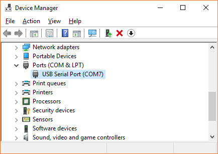
Gator:control ProtoSnap Hookup Guide

$
0
0

Gator:control ProtoSnap Hookup Guide a learn.sparkfun.com tutorial

Available online at: http://sfe.io/t822

Introduction

The gator:control is one of a series of gator-clippable boards called gator:boards that SparkFun has created to interface with the micro:bit and gator:bit expansion for micro:bit. The gator:control contains two buttons, an on/off slide switch, and a reed switch, which is activated by a magnet. In this hookup guide, we’ll go over how to hook up each of the individual boards, along with some examples involving all of the boards together.

SparkFun gator:control ProtoSnap

SparkFun gator:control ProtoSnap

COM-14968
$9.95

Required Materials

For this activity, you’ll of course need a micro:bit. You’ll also need some alligator clips to connect everything together, and a micro-b USB cable to program your micro:bit. A magnet is also a good addition to the mix, as this is the only way to activate the reed switch. All of these things are shown below, so grab them if you haven’t already. You can go ahead and grab a gator:bit as well to create some more robust projects, but you’ll be able to get along fine with just a micro:bit.

micro:bit Board

micro:bit Board

DEV-14208
$14.95
5
SparkFun gator:bit

SparkFun gator:bit

DEV-14484
$19.95
Alligator Test Leads - Multicolored (10 Pack)

Alligator Test Leads - Multicolored (10 Pack)

PRT-12978
$2.95
3
Magnet Disk - 0.709"

Magnet Disk - 0.709"

COM-08890
$0.95
USB Micro-B Cable - 6"

USB Micro-B Cable - 6"

CAB-13244
$1.95
3
SparkFun gator:color ProtoSnap

SparkFun gator:color ProtoSnap

COM-14890
$9.95

Suggested Reading

If you decide to use the gator:bit and it's your first time using the board, check out the gator:bit Hookup Guide.

Gator:bit Hookup Guide

May 10, 2018

Gator:bit is a rugged development breakout board for the BBC micro:bit. Gator:bit exposes almost every pin on the micro:bit to an alligator clippable pad. Gator:bit features over-voltage, over-current, and short circuit protection circuitry on every IO pin as well as built-in addressable LEDs, built-in buzzer, and a power management solution to give you sensible powering options.

Also, if you’re starting out with electronics and aren’t familiar with the following concepts, we recommend checking out these tutorials before continuing.

What is a Circuit?

Every electrical project starts with a circuit. Don't know what a circuit is? We're here to help.

Voltage, Current, Resistance, and Ohm's Law

Learn about Ohm's Law, one of the most fundamental equations in all electrical engineering.

What is Electricity?

We can see electricity in action on our computers, lighting our houses, as lightning strikes in thunderstorms, but what is it? This is not an easy question, but this tutorial will shed some light on it!

Light-Emitting Diodes (LEDs)

Learn the basics about LEDs as well as some more advanced topics to help you calculate requirements for projects containing many LEDs.

Analog vs. Digital

This tutorial covers the concept of analog and digital signals, as they relate to electronics.

Getting Started with the micro:bit

The micro:bit is a compact, powerful programming tool that requires no software installation. Read on to learn how to use it YOUR way!

Hardware Overview

The gator:control contains four boards in the main assembly, all of which can be broken out of the main board for individual use. Buttons or switches allow you to create a point in a circuit that can either be closed (connected) or open (disconnected). Most buttons, including the ones on the gator:control, will be a closed circuit only when they are being pressed. These buttons on the gator:control are highlighted below.

Buttons

Buttons

The second type of control element on the gator:control is the slide switch. This will be a closed circuit when the switch is in the ON position and an open circuit when the switch is in the OFF position. The slide switch is highlighted on the gator:control below.

Slide Switch

Slide Switch

The final type of control element is the reed switch, which is controlled by a magnet. The reed switch will act as a closed circuit when you bring a magnet sufficiently close to the switch. The reed switch is shown highlighted in the image below.

Reed Switch

Reed Switch

Examples

There are two ways that you can use these buttons or switches in your circuit. One would be as a part of a simple circuit, allowing the button or switch to complete and close your circuit, the other would be to use the button or switch as a digital input to control an already completed and closed circuit. We’ll demonstrate these two ways to use buttons and switches by turning on an LED. For this example, we’d recommend using a gator:LED from the gator:color because you won’t have to worry about a resistor.

Simple Button

In the first circuit, we’ll connect a button so that it is a part of the LED circuit. We will complete the circuit by pressing down on the button. This will close the circuit so that current will flow through our button and power the LED. As soon as you stop pressing on the button, the circuit is open causing the LEDs to not light up. To set this circuit up, connect the 3V pin on your micro:bit to one side of a button, connect the other side of the button to the + side of a gator:LED, then connect the - side of the gator:LED to the ground pin on the micro:bit. The circuit should look like the below image. The connections can be seen by matching the colors of the alligator clips.

Simple Button Circuit

Simple Button Circuit

Clicking the button should turn the light on if you’ve set everything up properly. Instead of using the button, try using the slide switch to control the LEDs. Flipping the switch to the ON position is the same as pushing the button down. When we turn the switch to ON position, we complete the circuit by closing. Flipping the switch to the OFF position will open the circuit back up causing the LEDs to not light up. You should see the same effect with the reed switch in place of the button. To complete the circuit, place a magnet above the reed switch to close the circuit. Removing the magnet will open the circuit back up.

Digital Button

In the second circuit, we will connect our button to a digital input and our LED circuit to a digital output. Then, when we click the button, the micro:bit will see a digital signal, and it will toggle the pin for the LED circuit on. To connect this circuit, connect one side of a button or switch to the ground pin, and the other side of the button to pin 0. Now connect pin 1 to the + end of the gator:LED and the - side of the gator:LED to the ground pin on the micro:bit. Your circuit should look something like the image below.

Digital Button Circuit

Digital Button Circuit

You may have noticed that we connect one end of the button to ground. This means that when we push the button, pin 0 will connect to ground and the micro:bit will read a digital low or 0 signal. However, when these digital pins are at rest, they’re low, so we’ll need to configure the micro:bit so that this pin rests in a high state. To do this with code, we add a pull-up resistor to pin 0 using the following block of code, located under Pins ->More ->set pull pin P0 to up.

Set Pull-Up

Set Pull-Up

This block will make it so that pin 0 will be a high logic level until we push our button, pulling the pin low. Now we need to have the micro:bit read the button pin to see if the button is pressed, then, using that information, decide on whether or not to turn on the light. To do this, we read the value of pin P0 into a variable named button_pin. From the Variables and Pin category, set the blocks of code to set button_pin todigital read pin P0.

Then we use an If...Else... loop to check the value of button_pin. If the value is 0, then that means the button is pressed, so we write pin P1 high. Otherwise, we write a low value to P1. Re-create the following code into your MakeCode editor or download the example by clicking the download button to test it out!

Note: You may need to disable your ad/pop-up blocker to interact with the MakeCode programming environment and simulated circuit!

Go ahead and give your button a click. The light will still turn on, but unlike the previous example, we’ve done this action digitally! The example code will also work with the slide switch and reed switch. Try replacing the connection with either switch to control the LEDs.

Resources & Going Further

Now that you’ve successfully got your gator:control up and running, it’s time to incorporate it into your own project! For more information about the gator:control board, check out the resources below:

Need some inspiration for your next project? Check out some of these related tutorials:

micro:bit Educator Lab Pack Experiment Guide

A quickstart guide for the micro:bit educator lab pack.

micro:arcade Kit Experiment Guide

We love games! We love writing games, building games and yes, even building game consoles. So we want to introduce to you the micro:arcade kit for the micro:bit!

How to Load MicroPython on a Microcontroller Board

This tutorial will show you how to load the MicroPython interpreter onto a variety of development boards.
New!

Gator:starter ProtoSnap Hookup Guide

Get started clipping sensors and lights to the micro:bit with the gator:starter gator:board from SparkFun!

learn.sparkfun.com | CC BY-SA 3.0 | SparkFun Electronics | Niwot, Colorado
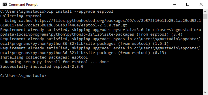
Gator:starter ProtoSnap Hookup Guide

$
0
0

Gator:starter ProtoSnap Hookup Guide a learn.sparkfun.com tutorial

Available online at: http://sfe.io/t819

Introduction

The gator:starter is one of a series of gator-clippable boards called gator:boards that SparkFun has created to interface with the micro:bit and gator:bit expansion for micro:bit. The gator:starter is a nice contained package of a temperature sensor, an RGB LED, and light sensor. In this hookup guide we’ll go over how to hook up each of the individual boards, along with some examples involving all of the boards together.

SparkFun gator:starter ProtoSnap

SparkFun gator:starter ProtoSnap

SEN-14891
$9.95

Required Materials

For this activity, you’ll of course a micro:bit. You’ll also need some alligator clips to connect everything together, and a micro-B USB cable to program your micro:bit. All of these things are shown below, so grab them if you haven’t already. The gator:bit is recommended if you’d like to add some more input and output to your micro:bit, but you’ll be able to get along fine with just a micro:bit.

micro:bit Board

micro:bit Board

DEV-14208
$14.95
5
SparkFun gator:bit

SparkFun gator:bit

DEV-14484
$19.95
Alligator Test Leads - Multicolored (10 Pack)

Alligator Test Leads - Multicolored (10 Pack)

PRT-12978
$2.95
3
USB Micro-B Cable - 6"

USB Micro-B Cable - 6"

CAB-13244
$1.95
3

Suggested Reading

If you decide to use the gator:bit and it's your first time using the board, check out the gator:bit Hookup Guide.

Gator:bit Hookup Guide

May 10, 2018

Gator:bit is a rugged development breakout board for the BBC micro:bit. Gator:bit exposes almost every pin on the micro:bit to an alligator clippable pad. Gator:bit features over-voltage, over-current, and short circuit protection circuitry on every IO pin as well as built-in addressable LEDs, built-in buzzer, and a power management solution to give you sensible powering options.

Also, if you’re starting out with electronics and aren’t familiar with the following concepts, we recommend checking out these tutorials before continuing.

What is a Circuit?

Every electrical project starts with a circuit. Don't know what a circuit is? We're here to help.

Voltage, Current, Resistance, and Ohm's Law

Learn about Ohm's Law, one of the most fundamental equations in all electrical engineering.

What is Electricity?

We can see electricity in action on our computers, lighting our houses, as lightning strikes in thunderstorms, but what is it? This is not an easy question, but this tutorial will shed some light on it!

Light-Emitting Diodes (LEDs)

Learn the basics about LEDs as well as some more advanced topics to help you calculate requirements for projects containing many LEDs.

Analog vs. Digital

This tutorial covers the concept of analog and digital signals, as they relate to electronics.

Getting Started with the micro:bit

The micro:bit is a compact, powerful programming tool that requires no software installation. Read on to learn how to use it YOUR way!

Hardware Overview

The gator:starter contains 3x boards that can be snapped out of the main assembly simply by twisting back and forth repeatedly. The available boards are:

  • temperature sensor (MCP9700)
  • common cathode RGB LED
  • light sensor (TEMT6000)

Temperature

The temperature sensor (MCP9700) is an analog sensor. Simply provide power to the sensor on 3.3V and GND. To read, you would connect the TEMP pin to the micro:bit’s analog input.

Temperature Sensor

Common Cathode RGB LED

The center component is a common cathode RGB LED. Each individual LED is connect to the GND pin. You would need one I/O pin per color to light up.

Common Cathode Tri-Color RGB LED

Light Sensor

The light sensor is also an analog sensor. Simply provide power to the sensor on the 3.3V and GND pin. To read, you would connect the LIGHT pin to a micro:bit’s analog input.

Light Sensor

Power Tabs

We’ve broken out the power (3.3V and GND) so it can be clipped to on the edge of the board for power without breaking each board away from the main board. These power pins are outlined in the image below.

Power Tabs

Power Tabs

There are also power tabs available on each board if you choose to break the gator:starter into its basic components. Try not to hook power up backwards! If you don’t break the board apart however, you’ll still be able to interface with all of the sensor and light pins.

Hardware Assembly

Connecting the gator:starter to the gator:bit is a relatively simple process that doesn’t even involve any soldering, all you’ll have to do is clip onto the tabs to make your connection. Let’s start by powering the gator:starter.

Power

When connecting power there are a few practices you should get used to doing. The first of these is to always connect ground (GND) first. Second, you want to make sure that you aren’t powering your device with the wrong voltage, as powering a 3.3V device with 5V could damage the device. Keeping these things in mind, go ahead and clip the ground of your gator:board to ground on the gator:bit. Once this is done, go ahead and do the same with 3.3V. Now that power is connected, we can go ahead and start connecting to our sensors.

Power Connected

Connected Power

Signals

Temperature Sensor

The temperature sensor onboard is an MCP9700 analog temperature sensor with a temperature range of -40°C to 125°C. This sensor outputs an analog signal so you’ll need to connect it to a pin on the gator:bit that is capable of reading an analog signal. The analog capable pins are pins 0, 1 and 2. Go ahead and clip the TEMP pin to any of those three pins.

RGB LED

The RGB LED is three LED’s (red, green and blue) all combined into a single package. It's a common cathode LED which means that all three of the LED’s share the same ground pin. To activate any color, simply make sure ground is connected, then connect 3.3V up to the color you’d like to turn on. Colors can be added and mixed simply by connecting more than one color. If you want to create even more colors, you can connect the LED to any of pins 0, 1 and 2 to allow for things like dimming and full color control.

Using with the gator:bit: If you are using the gator:bit, keep in mind that you'll have to use pins P20, P19, P15, P14 or P13 to drive your LEDs, as the protection circuitry on the rest of the gator:bit pins does not create a high enough voltage to drive some colors of LED.

Light Sensor

The light sensor onboard is a TEMT6000 ambient light sensor. This sensor is also an analog sensor, so once again we’ll only be able to use it with pins 0, 1 and 2. To connect this sensor, just clip the LIGHT tab to any of the three analog pins.

Using MakeCode

So you’ve connected your sensors and LED to the gator:bit, but how do we get useful information from these sensors? Luckily, SparkFun has written a few MakeCode packages to allow the gator:bit to make sense of the values that come in from the MCP9700 temperature sensor and TEMT6000 light Sensor.

Installing the Gatortemp Package for Microsoft MakeCode

To download the MakeCode package for the light sensor, go to Advanced ->Add Package. Then copy and paste the following link into the search bar:

https://github.com/sparkfun/pxt-gator-temp

Clicking on the gator:temp will add it to your list of usable packages in Advanced. Go ahead and open the package and you’ll see a block that allows you to get the temperature on the pin that the gator:temp is connected to.

gator:temp Block

gator:temp Block

RGB LED

With the three primary colors, we’re able to mix colors to create any color we like. LED’s are either on or off, with no brightness in between, so we control brightness by turning the light on and off very fast in a process known as pulse width modulation (PWM). The common cathode LED does not require any additional MakeCode packages. To use PWM, go to Advanced->Pins and select the analog write block, shown below.

Analog Write Block

Analog Write Block

You’ll need three of these blocks, one to control each color of the LED. Make sure the pin selected in the block is connected to the proper color (P0 = Red, P1 = Green, P2 = Blue). The analog write block defaults to a value of 1023, or 100%. If you wanted to turn the light down to 50% brightness, you’d plug a value of 511 into your analog write function. This allows for really any color to be created. For instance orange would be created by writing 100% (1023) to red and 10% (102) to green.

Installing the Gatorlight Package for Microsoft MakeCode

To download the Makecode package for the light sensor, go to Advanced->Add Package. Then copy and paste the following link into the search bar:

https://github.com/sparkfun/pxt-gator-light

Clicking on the gator:light will add it to your list of usable packages in Advanced.

Adding a package

Adding a Package

Go ahead and open the package to take a look at the variable block we are now able to use. There are two drop down menus that you can use to change which pin the light sensor is attached to as well as the units of the measurement.

Get Light Block

Get Light Block

The light sensor measures light in terms of illuminance, or lux. If you’re unfamiliar with illuminance, it’s basically just a measure of the amount of light reaching a certain spot. The units can either be the raw value from the analog-to-digital converter (ADC) or in units of lux. Check out the chart below to get an idea for what this lux value corresponds to in terms of some common lighting situations.

illuminance

Table of Lux Values Courtesy of Wikipedia: Lux

This block can be used to modify the value of a variable in MakeCode.

Examples

Simple Thermometer

Hardware Hookup

In this example, we’ll use Makecode and the gator:temp to create a simple thermometer. The goal is to read the temperature from the sensor, then have the micro:bit display the number as scrolling text. To start, go ahead and power the gator:temp by clipping to the micro:bit, then connect the temp pin to pin 0 on the micro:bit (It’s also possible to connect to pins 1 or 2) This will allow the micro:bit to read the analog value on pin 0.

MakeCode

Now we need to program our micro:bit using Makecode to do what we want. In this example, we only need to display the value of the temperature once, so we won’t need to create a variable to store the value. In fact, all we’ll need to do is use the Show Number block under Basic. What we’ll need to do is replace the 0 in the Show Number block with the Get Temperature block in our gator:temp MakeCode package. This will make the micro:bit read the temperature from pin 0 and show the temperature on the LED screen. Re-create the following code into your MakeCode editor or download the example by clicking the download button to test it out!


Uploading the above code to your micro:bit will result in something like the following gif.

Temperature Display

Temperature Display

Light Indicator

Hardware Hookup

In this example, we’ll go through how to use the gator:light in conjunction with the gator:RGB to create a simple light indicator. Our goal for this example is to create a light indicator to show blue when it’s dark, red when it’s bright, and shades of purple for everything in between. To begin let’s connect all of our components up to one another before we upload code. Begin by powering the gator:temp and connecting the light pin to pin 0. We will then ground the gator:RGB, and connect red and blue to pins 1 and 2, respectively. This will allow the gator:bit to control red and blue on the gator:RGB.

MakeCode

Now let’s move on to the Makecode portion, which will tell our micro:bit how to behave. First we need to create a variable to store the value of our light in from the Variables category. Let’s call it lightValue for sake of simplicity. Then let's set the lightValue variable to the value that we are reading from our light sensor on pin 0. Use the block in Gatorlight to read the pin P0. Since we’re going to be writing this value directly to our LED, we can select units of adcVal from the second dropdown menu. As an ADC (Analog to digital conversion) value has the same range of possible values as the values that we can write to our LED (both range from 0 to 1023). Re-create the following code into your MakeCode editor or download the example by clicking the download button to test it out!

If things are pretty bright outside, the value will be closer to 1023. So you’ll end up writing a value that’s close to 100% percent brightness to the LED on pin 2 (Blue, if you hooked things up correctly) and a value that’s closer to 0 on pin 1 (Red). Moving the light sensor into darkness should give you more red, while bright light should yield blue. Experiment and see how something like a flashlight affects the sensor.

Light Indicator

Light Indicator

Resources & Going Further

Now that you’ve successfully got your gator:starter up and running, it’s time to incorporate it into your own project! For more information about the board, check out the resources below:

Need some inspiration for your next project? Check out some of these related tutorials:

Getting Started with the micro:bit

The micro:bit is a compact, powerful programming tool that requires no software installation. Read on to learn how to use it YOUR way!

micro:climate Kit Experiment Guide

A weather station kit that is built on top of the inexpensive, easy-to-use micro:bit and Microsoft MakeCode.

micro:arcade Kit Experiment Guide

We love games! We love writing games, building games and yes, even building game consoles. So we want to introduce to you the micro:arcade kit for the micro:bit!

learn.sparkfun.com | CC BY-SA 3.0 | SparkFun Electronics | Niwot, Colorado

Gator:color ProtoSnap Hookup Guide

$
0
0

Gator:color ProtoSnap Hookup Guide a learn.sparkfun.com tutorial

Available online at: http://sfe.io/t821

Introduction

The gator:color is one of a series of gator-clippable boards called gator:boards that SparkFun has created to interface with the micro:bit and gator:bit expansion for micro:bit. The gator:color has a smattering of a different color LEDs that can be used either in place or broken away from the main board. In this hookup guide we’ll go over how to light up our LEDs, both by simply turning them on and also by dimming them using a process called Pulse Width Modulation (PWM).

SparkFun gator:color ProtoSnap

SparkFun gator:color ProtoSnap

COM-14890
$9.95

Required Materials

For this activity, you’ll of course need a micro:bit. You’ll also need some alligator clips to connect everything together, and a micro usb cable to program your micro:bit. All of these things are shown below, so grab them if you haven’t already. You can go ahead and grab a gator:bit as well to create some more robust projects, but you’ll be able to get along fine with just a micro:bit.

micro:bit Board

micro:bit Board

DEV-14208
$14.95
5
SparkFun gator:bit

SparkFun gator:bit

DEV-14484
$19.95
Alligator Test Leads - Multicolored (10 Pack)

Alligator Test Leads - Multicolored (10 Pack)

PRT-12978
$2.95
3
USB Micro-B Cable - 6"

USB Micro-B Cable - 6"

CAB-13244
$1.95
3

Suggested Reading

If this is your first time using a gator:bit, check out the gator:bit Hookup Guide.

Gator:bit Hookup Guide

May 10, 2018

Gator:bit is a rugged development breakout board for the BBC micro:bit. Gator:bit exposes almost every pin on the micro:bit to an alligator clippable pad. Gator:bit features over-voltage, over-current, and short circuit protection circuitry on every IO pin as well as built-in addressable LEDs, built-in buzzer, and a power management solution to give you sensible powering options.

Also, if you’re starting out with electronics and aren’t familiar with the following concepts, we recommend checking out these tutorials before continuing.

What is a Circuit?

Every electrical project starts with a circuit. Don't know what a circuit is? We're here to help.

Voltage, Current, Resistance, and Ohm's Law

Learn about Ohm's Law, one of the most fundamental equations in all electrical engineering.

What is Electricity?

We can see electricity in action on our computers, lighting our houses, as lightning strikes in thunderstorms, but what is it? This is not an easy question, but this tutorial will shed some light on it!

Light-Emitting Diodes (LEDs)

Learn the basics about LEDs as well as some more advanced topics to help you calculate requirements for projects containing many LEDs.

Analog vs. Digital

This tutorial covers the concept of analog and digital signals, as they relate to electronics.

Getting Started with the micro:bit

The micro:bit is a compact, powerful programming tool that requires no software installation. Read on to learn how to use it YOUR way!

Hardware Overview

The gator:color is perfect if you want to add a low-profile glowing component to your project. The gator:color contains 6 monochrome LEDs, which means that each light only emits one color. On board there are two white LEDs, along with one each of red, green, blue, and yellow LEDs. The board has power tabs broken out on the edges so that the board doesn’t have to be broken apart to light up the LEDs.

Powering your LEDs

The LEDs can be powered through either of two ways. The first simply turns the LEDs on, and is done by clipping the - side of the LED to ground on the micro:bit and connecting the + to 3V on the micro:bit. The other way to control these LEDs would be to connect the gator:color’s Power to pins 0, 1 or 2 on the micro:bit (with Ground connecting to Ground). This method gives you more control over your LEDs, allowing you to turn the LEDs on and off with the micro:bit, as well as change the brightness level using Pulse width modulation (PWM).

Power Tabs

Power Tabs

If and when you choose to incorporate your gator:color LEDs into a project, there is also a breakout power strip at the top of the board that you can use.

Power Rail

Power Strip

Breaking Apart Your Board

Each of the LEDs can be broken away from the board to be lit individually. To do so, twist the LED board gently from side to side until it pops out. The connection points are highlighted in the image below.

break points for gator:color LED tabs

Break points for gator:color LED tabs

The Power Strip breaks out in a similar manner as the LED boards. Break points are highlighted below.

break points for gator:color power strip

Break points for gator:color power strip

Hardware Assembly

Let’s start by simply turning the LEDs on. Using your alligator clips, connect the - side of the LED to ground on the micro:bit and connect the + to 3.3V on the micro:bit. You should see all of the gator:color’s LEDs light up. This type of setup is shown in the photo below.

Normal Connection

Click on the image for a closer look

If you want to dim the LED or control it with the micro:bit, you can connect the + on the LED to any of pins 0, 1 or 2. LEDs are either on or off, with no brightness in between, so we control brightness by turning the light on and off very fast in a process known as PWM. Connect your pins as you see in the image below and we’ll go over the code necessary to dim your LEDs in the next section.

Dimming Connection

Click on the image for a closer look

Using with the gator:bit If you are using the gator:bit, keep in mind that you'll have to use pins P20, P19, P15, P14 or P13 to drive your LEDs, as the protection circuitry on the rest of the gator:bit pins does not create a high enough voltage to drive some colors of LED.

Using MakeCode

As you’ve seen, it’s pretty simple to get your LEDs to simply light up; just connect power to power and ground to ground. However, if you want to do some fancy dimming or flashing effects, you’ll need to upload some code to your micro:bit.

If you’ve never used MakeCode before, refer to the Using MakeCode section of our Getting Started with the Micro:Bit.

Getting Started with the micro:bit

March 21, 2017

The micro:bit is a compact, powerful programming tool that requires no software installation. Read on to learn how to use it YOUR way!

Dimming LEDs is done using Pulse Width Modulation. To use PWM in MakeCode, go to Advanced->Pins and select the analog write block, shown below.

Analog Write Block

Analog Write Block

The analog write block defaults to a value of 1023, or 100%. If you wanted to turn the light down to 50% brightness, you’d plug a value of 511 into your analog write function. Of course, you also want to make sure that whichever pin is selected in the MakeCode block is the pin that is clipped to the + pin on the LEDs. This can be done with any of the LEDs to create patterns with different brightnesses or even flashing LEDs.

Example: LED Pulse

The following example will gradually turn the LEDs up to full brightness, then gradually go back down. This will fade the LED’s on and off. To do this, we write the value LightValue (Which we initialize to 0 in our on start function) to our analog pin P0 (3.3V from the LED’s should be connected to this pin). We then add lightStep (which we set to 5 in our on start function) to LightValue, which changes the brightness by a tiny amount. Once LightValue reaches its maximum (1023) we multiply lightStep by -1, changing the value of lightStep to -5. This means that when we add lightStep to LightValue, LightValue will decrease. We do the same thing (multiply by -1) when LightValue reaches 0 to flip the direction around again. Finally, we add a delay of our choosing from Advanced->Control in to slow our fade down a little bit. The whole program is shown below.

Pulsing LED Code

Resources & Going Further

Now that you have the hang of the gator:color, what will you light up? Have a look at some of the resources below for more information and inspiration!


For additional SparkFun tutorials, check out some of these related micro:bit tutorials:

micro:bit Breakout Board Hookup Guide

How to get started with the micro:bit breakout board.

How to Load MicroPython on a Microcontroller Board

This tutorial will show you how to load the MicroPython interpreter onto a variety of development boards.
New!

Gator:starter ProtoSnap Hookup Guide

Get started clipping sensors and lights to the micro:bit with the gator:starter gator:board from SparkFun!
New!

Gator:control ProtoSnap Hookup Guide

Buttons and switches and inputs oh my! Start adding more control to your gator:bit with the SparkFun gator:control.

learn.sparkfun.com | CC BY-SA 3.0 | SparkFun Electronics | Niwot, Colorado


How to Make a Custom EL Wire Extension Cable

$
0
0

How to Make a Custom EL Wire Extension Cable a learn.sparkfun.com tutorial

Available online at: http://sfe.io/t808

Introduction

In this tutorial, we will make a custom EL Wire extension cable as an alternative to splicing wire.

EL Wire Extension Cable Between EL Wire Sewn in Clothing and an Inverter Placed in a Pocket

This is useful if you need to:

  • extend the cable on the EL wire to an EL Inverter
  • easily disconnect the EL Wire if the inverter is in an enclosure or attached to a separate piece of clothing
  • provide additional flexibility for the cable to move around in wearable projects

Required Materials

To follow along with this project tutorial, you will need the following materials. You may not need everything though depending on what you have. Add it to your cart, read through the guide, and adjust the cart as necessary.

SparkFun Snappable Protoboard

SparkFun Snappable Protoboard

PRT-13268
$7.95
11
JST Jumper 2 Wire Assembly

JST Jumper 2 Wire Assembly

PRT-09914
$0.95
3

Tools

You will need a soldering iron, solder, and general soldering accessories.

Solder Lead Free - 100-gram Spool

Solder Lead Free - 100-gram Spool

TOL-09325
$7.95
7
Weller WLC100 Soldering Station

Weller WLC100 Soldering Station

TOL-14228
$44.95

You Will Also Need

  • Electrical Tape
  • Hot Glue
  • Hot Glue Gun
  • Scissors

Suggested Reading

If you aren’t familiar with the following concepts, we recommend checking out these tutorials before continuing.

How to Solder: Through-Hole Soldering

This tutorial covers everything you need to know about through-hole soldering.

Getting Started with Electroluminescent (EL) Wire

This guide will help you get started with electroluminescent (EL) wire, tape, panel, chasing wire, and bendable wire to let your project glow!

How to Work w/ Jumper Pads and PCB Traces

Handling PCB jumper pads and traces is an essential skill. In this tutorial, you will learn how to cut a PCB trace and add a solder jumper between pads to reroute connections. You will also learn how to repair a trace with the green wire method if a trace is damaged.

Hardware Assembly

First, break off a 2x6 grid of plated through holes from the snappable protoboard.

Snap Off 2x6 Grid Snappable ProtoBoard

Insert the JST connector connected to the jumper wire assembly such that the socket's end is flush with the board. This should be 3x plated through holes into the grid.

Insert JST Connector

Loop the wire around and insert the tinned wires on the opposite end so that they are adjacent to the JST connector's pins. To be consistent, connect the red wire's terminals together. Repeat for the black wire. Leave some room with 4x through holes at the end of the protoboard to reinforce the wire connection and provide some strain relief.

Insert Tinned Wires into Protoboard

Add a solder jumper between the pin and wire for the red wire. Repeat for the black wire. When finished, remove the JST connector from the socket.

Add Solder

Remember, EL wire runs on AC power. It’s important to mention that the AC power coming from the inverter is not enough to hurt or kill you. However, it is enough to give you a good shock so it is a good idea to insulate the connection. Start by wrapping a piece of electrical tape around the middle of the JST connector's socket.

Insulate Connection with EL Tape

Add a drop of hot glue in the middle to secure the piece of tape and connection further. Make sure to not get any hot glue inside the JST connector's socket.

Hot Glue Under Electrical Tape to Reinforce Wire to Board Connection on EL Wire Extension Cable

Finish wrapping the remaining electrical tape around the cable. The electrical tape will become tapered as you move away from the JST connector.

Finished EL Wire Extension Cable

Add the extension cable between the inverter and EL wire. In the image below, the EL Wire extension cable provided easy access to the EL inverter battery pack from a hoodie's pocket.

EL Wire Extension Cable between EL Inverter and EL Wire

Resources and Going Further

Now that you’ve successfully made a custom EL Wire extension cable, it’s time to incorporate it into your own project! Need some inspiration for your next project? Check out some of these related tutorials:

ELasto-Nightlight

Fear the dark no longer with this ELastoLite nightlight.

Getting Started with Electroluminescent (EL) Wire

This guide will help you get started with electroluminescent (EL) wire, tape, panel, chasing wire, and bendable wire to let your project glow!

Prototype Wearable LED Dance Harness

A project tutorial to add an extra effect for dancers performing a choreographed piece. The harness can be added quickly under a costume.
New!

EL Wire Hoodie

In this tutorial, we will sew standard EL wire to a hoodie.

learn.sparkfun.com | CC BY-SA 3.0 | SparkFun Electronics | Niwot, Colorado
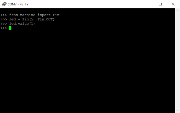
EL Wire Hoodie

$
0
0

EL Wire Hoodie a learn.sparkfun.com tutorial

Available online at: http://sfe.io/t770

Introduction

The design and build time of this project depends on your experience manually sewing, the length of EL wire used, and where you are sewing it to. This can take about ~1 - 3 hours if you are following the edges of a hoodie.

In this tutorial, we will sew standard EL wire onto a hoodie.

EL Hoodie

Required Materials

To follow along with this tutorial, you will need the following materials. We will be using a standard EL wire on the hoodie. You may not need everything, depending on what you have and your setup. Add it to your cart, read through the guide, and adjust the cart as necessary.

1500 mAh Alkaline Battery - AA

1500 mAh Alkaline Battery - AA

PRT-09100
$0.50
EL Inverter - Battery Pack

EL Inverter - Battery Pack

COM-11222
$4.95
3
EL Wire - White 3m

EL Wire - White 3m

COM-10197
$9.95

Tools

At a minimum, you will need a needle. If you are making an extension cable, you will need a soldering iron, solder, and general soldering accessories.

Needle Set

Needle Set

TOL-10405
$1.95

You Will Also Need

  • Hoodie
  • Clear Thread or Fishing Line
  • Binder Clips, Pins, or, Tape
  • Scissors

Suggested Reading

If you aren’t familiar with the following concepts, we recommend checking out these tutorials before continuing.

Getting Started with Electroluminescent (EL) Wire

This guide will help you get started with electroluminescent (EL) wire, tape, panel, chasing wire, and bendable wire to let your project glow!

Planning a Wearable Electronics Project

Tips and tricks for brainstorming and creating a wearables project.
New!

How to Make a Custom EL Wire Extension Cable

In this tutorial, we will make a custom EL Wire extension cable as an alternative to splicing wire.

Prepare the EL Wire

Testing the EL Wire and EL Inverter

Before sewing the EL wire to a piece of clothing, make sure to test it out to see if it is functioning. To test, connect the EL wire to an inverter. In this case, we are using AA batteries and the 3V EL inverter battery pack.

Insert EL Wire's JST Connector into EL Battery Pack

With the battery in the EL inverter battery pack, press the button to test. If the EL wire lights up, both the EL wire and EL inverter are good to go!

EL Wire Lit Up

Planning the Path

Plan out where to add EL wire. While you can sew the EL wire on the arms, it will be harder due to the amount of room available to work with in the arm. The easiest would be to follow the edge of the hoodie. To hold down the EL wire when sewing, we will be using binder clips. Depending on what you have, you could also try to use pins or tape. Place the EL wire into the binder clip and clamp it down against on the fabric. Make sure to avoid clamping the EL wire down where the binder clip pinches as this can damage the corona wires.

EL Wire Held to the Hoodie with a Binder Clip

In this case, all 3 meters were used for EL wire starting under the pocket, running up the side of the zipper, around the shoulders, up to the brim of the hood, around the shoulders, down the zipper, and ending at the pocket on the other side. Make sure to avoid sharp bends. If you decide to use a shorter length, you can cut the EL wire. Just make sure to re-seal the cut end with hot glue, otherwise you could end up getting a good jolt..

Front of EL Hoodie with Binder ClipsBack of EL Hoodie with Binder Clips

Having a hard time seeing the binder clips and EL wire? Click on the images for a closer look

Prepare the Needle and Thread

For this tutorial, we will double up the clear thread. Prepare your needle and thread by inserting the end of the clear thread through the eye (opening) of the needle and pull it through. Cut about an arms length of thread (approximately 2 feet long) to work with. Tie the two ends of the fishing wires into a knot. You may need to use the needle to help guide the knot close to the end of the thread.

Pulling the Knot Closer To the End Using a Needle

Repeat the steps again for a second knot. Cut of any excess tail left over.

Clear Thread Tied in a Knot

Sewing EL Wire

Start sewing at the EL wire’s heat shrink and tie a knot around the EL wire. Continue making a loop around the EL wire to hold it down. When sewing with clear thread, make sure to pull the thread all the way through since the thread is slippery when sewn in certain fabrics. Be careful not to sew the front and back of the hoodie together. Also, ensure that the distance between each stitch is not too long. About 0.5" to 1.0" is a good stitch. Longer stitches can cause the EL wire to snag or become loose when wearing the EL hoodie.

Start Sewing at the Heat Shrink of the EL Wire

After about 5x stitches, loop back through the last stitch with a overhand knot to lock the thread in and prevent it from sliding.

Tying a Knot After 5x Stitches to Prevent the Clear Thread from Sliding

Continue sewing and remove any binder clips holding the EL wire down against the fabric. When sewing EL along the zipper, avoid looping the thread against the zipper.

Sewing EL Wire Beside Zipper

While sewing the EL wire, try holding the EL down against the fabric using your non-dominant hand. Pinch below the area that you are sewing using your thumb and ring finger. Then pinch above the area that you are sewing using your index and middle finger. This keeps the center area (where you will be working with the needle) taut so that it is easier to sew.

Repeat the Steps Outlined Above

Once you begin to run out of thread to work with, tie the clear thread down against the fabric. Then repeat the steps outlined above with another piece of clear thread.

Clear Thread Tied in a Knot

When you are finished sewing the EL wire down, make a loop with the end of the EL wire cable and sew the wire down for strain relief. Make sure this loop is in the wiring beyond the heat shrink, as the connection at the heat shrink is sensitive to bending.

Strain Relief

Plug the EL wire back into the EL inverter to test it out. If it lights up, you are good to go! Place the EL inverter in a pocket or clip to a belt to enjoy!

EL Wire in Pocket

Remember, EL wire works best in low light. It may be hard to see in daylight or in rooms with sources of light.

EL Hoodie in Room with Sources of Light

Front EL Wire Hoodie Low LightBack EL Wire Hoodie Low Light

Different Hoodie Sizes

Remember what I said about the size of the hoodie? Different hoodie sizes will require different lengths of EL wire - this variation can cause the EL wire to not start or end where you expect it to. Note the difference in the image in the bottom right.

Youth Medium Hoodie with EL WireYouth Large Hoodie with EL Wire
Youth Medium with EL WireYouth Large with EL Wire

Sewing Into The Arms

Looking for a challenge? Sewing EL wire onto the arms can be difficult depending on the fabric being used and the amount of space you have to work with. Three pieces of corrugated cardboard were custom cut to fit inside a hoodie’s arm to help with sewing. To assemble, cut half way into the cardboard about 0.5"-1"“ away from the edge. It does not have to be perfect. Slide the cardboard pieces together and hot glue the joints.

Front View of Cardboard Braket

Front View of Cardboard Bracket

Trim down the edges as necessary to slide into the arm with ease.

Top-Side View of Cardboard BracketFront-Side View of Cardboard Bracket
Top-Side ViewFront-Side View

Once cut and assembled, insert the bracket into an arm.

Cardboard Bracket In Arm

Clamp the fabric material down against the cardboard bracket and ensure that the fabric material is taut. Continue sewing clear thread down/up the arm.

Binder Clips Clipping Down Fabric Against Cardboard Bracket

The following shows standard EL wire sewn into the arms of an adult medium hoodie.

Front View Adult Medium with EL Wire Sewn into ArmsFront and Side View Adult Medium with EL Wire Sewn into Arms
Front View with EL Wire Sewn into ArmsFront-Side View with EL Wire Sewn into Arms

Resources and Going Further

Need some inspiration for your next project? Check out some of these related tutorials:

EL Wire Light-Up Dog Harness

Learn how to create a light-up dog harness using EL wire for when you need to take your four-legged friend for a walk in the dark.

Heartbeat Straight Jacket

An EL project that displays one person's heartbeat on another person's costume.

Sound Reactive EL Wire Costume

Learn how to make your EL wire costumes sound reactive in this project tutorial.

Prototype Wearable LED Dance Harness

A project tutorial to add an extra effect for dancers performing a choreographed piece. The harness can be added quickly under a costume.

Looking for more ideas, check out these related blog posts:


learn.sparkfun.com | CC BY-SA 3.0 | SparkFun Electronics | Niwot, Colorado

TSH82 Configurable OpAmp Hookup Guide

$
0
0

TSH82 Configurable OpAmp Hookup Guide a learn.sparkfun.com tutorial

Available online at: http://sfe.io/t818

Introduction

The TSH82 Configurable OpAmp board was designed to give you the best combination of performance and flexibility that we could achieve. The TSH82 device itself has 2 gain stages, each one independently accessible via header. Each stage is natively configured as an inverting amplifier, giving you a gain of -4.7 with AC input coupling. Stringing both stages together gives you a gain of about 22. But with the use of the jumpers on the back of the board, you can additionally configure each stage for non-inverting operation, differential input, and DC input coupling. The board will also operate with a single-ended DC power supply of 4.5V to 12V, or a bipolar supply from +/-2.25V to +/-6V.

SparkFun Configurable OpAmp Board - TSH82

SparkFun Configurable OpAmp Board - TSH82

BOB-14874
$4.95

Required Materials

In order to get signals in and out of the board, you’re going to have to solder some stuff together. You may not need everything on this list, depending on what you have. Add it to your cart, read through the guide, and adjust the cart as necessary.

Suggested materials

In order to tailor the board to your specifications, you might want some other parts that we can offer.

Resistor Kit - 1/4W (500 total)

Resistor Kit - 1/4W (500 total)

COM-10969
$7.95
147
Female Headers

Female Headers

PRT-00115
$1.50
7
Break Away Male Headers - Right Angle

Break Away Male Headers - Right Angle

PRT-00553
$1.95
4
Electrolytic Decoupling Capacitors - 10uF/25V

Electrolytic Decoupling Capacitors - 10uF/25V

COM-00523
$0.45
Rotary Potentiometer - 100k Ohm, Linear (Panel Mount)

Rotary Potentiometer - 100k Ohm, Linear (Panel Mount)

COM-14622
$1.50
Rotary Potentiometer - 250k Ohm, Logarithmic (Panel Mount)

Rotary Potentiometer - 250k Ohm, Logarithmic (Panel Mount)

COM-14623
$1.95

You may also want to examine these signals in real time as you’re working with them, or maybe generate a signal to run through your opamp board.

Digilent Analog Discovery 2

Digilent Analog Discovery 2

TOL-13929
$279.95
13
SparkFun MiniGen - Pro Mini Signal Generator Shield

SparkFun MiniGen - Pro Mini Signal Generator Shield

BOB-11420
$29.95
3
Frequency Generator Kit - FG085

Frequency Generator Kit - FG085

KIT-11394
$59.95
29
Digital Storage Oscilloscope - 100MHz (TBS2104)

Digital Storage Oscilloscope - 100MHz (TBS2104)

TOL-14925
$2,190.95

Suggested Reading

If any of this is new to you, have a look through these - the OpAmp intro with LT Spice is particularly good as an opamp primer.

How to Solder: Through-Hole Soldering

This tutorial covers everything you need to know about through-hole soldering.

Working with Wire

How to strip, crimp, and work with wire.

How to Use an Oscilloscope

How to work the dials and buttons on an oscilloscope, and a glossary of the o-scope lexicon.

Introduction to Operational Amplifiers with LTSpice

Picking up where we left off in "Getting Started with LTSpice," we delve a little deeper into LTSpice through an introduction of Operational Amplifiers (OpAmps).

Hardware Overview

The TSH82 Configurable OpAmp Board is meant to be hacked on, so you’ll want to be familiar with the sections of the circuitry.

On the far left side of the board is the power and reference section, the middle section covers stage 1 of the amplifier, and the far right side has stage 2. Each section also has three corresponding pins directly below in the picture.

Power and Reference

Positive voltage goes into +VCC, and negative voltage (or ground) goes into -VEE. The board generates an onboard reference voltage by way of two 2.2k 1% resistors decoupled with 10.1uF, giving a value halfway between +VCC and -VEE with a low frequency cutoff of about 15Hz. If you need better performance, VREF is accessible from the header and can be driven to any voltage between +VCC and -VEE without damaging the board.

Front side of board with Power and Reference Highlighted

Power and reference

Stages One and Two

Electrically speaking, the stages are identical. The default configuration is inverting with a gain of -4.7 with a bandwidth of almost 10MHz. Signal input is on -IN1 and output is taken from OUT1 (or -IN2 and OUT2 for stage two). Input signals are AC coupled with 1.0uF caps, and the input impedance is 10K with a low frequency cutoff of 15.9Hz. Outputs are DC coupled, so don’t forget to add a capacitor to the output if you’re running a single-ended supply and need to strip out the DC component. Of course, this isn’t an issue if you’re running the output of stage 1 to the input of stage 2.


Stage 1Stage 2

All Those Jumpers

On the back of the board you’ll find 10 solder jumpers that can be used to change the board’s performance, but nothing there needs to be changed to use it in it’s default state. To demonstrate how to use the jumpers, we’ll first describe their functions, then show you different circuit configurations with corresponding jumper settings. For the sake of clarity, it might be a good idea to have the schematic open for reference as you read through the jumper settings description.


Stage 2Stage 1

Input signal path:

  • JP1 and JP2 - 3 way solder jumpers used to change the input signal path in Stage 1.
    • JP1 - inverting input
    • JP2 - non-inverting input
  • JP3 and JP4 - 3 way solder jumpers used to change the input signal path in Stage 2.
    • JP3 - inverting input
    • JP4 - non-inverting input

There are small traces within these jumpers to set the default inverting configuration that will have to be cut out if you wish to change to differential or non-inverting configurations.

AC vs DC coupling

  • JP5 and JP6 - 3 way solder jumpers used to select between AC and DC coupling for the inputs to Stage 1.
    • JP5 - inverting input
    • JP6 - non-inverting input
  • JP7 and JP8 - 3 way solder jumpers used to select between AC and DC coupling for the inputs to Stage 2.
    • JP7 - inverting input
    • JP8 - non-inverting input

Vref

  • JP9 - allows the user to tie the non-inverting input of stage 1 to Vref through a 47k resistor for differential operations.
  • JP10 - same functionality as JP9 but for stage 2

As you can see, there are a lot of options. But if any of that leaves you confused, let us show you some workable configurations!

Configurations

Inverting, Gain = -4.7, AC-coupled Input, 0-10V Supply (Default)

This is the easiest configuration to use as it requires no changes to the jumpers on the board.

In the picture below, the jumper settings for this default mode are highlighted for your reference. Note the small traces bridging the pads of the solder jumpers. If the board does not perform as expected, double check that these traces are still present. If they’re not, just replace them with a blob of solder to make the default connections as shown here.

Picture of bottom of board with default jumper positions circled

+10VDC power input is on +VCC and ground is on -VEE. Vref will assume a value near +5V.

For stage 1, signal input is between -IN1 and -VEE, and output is taken between OUT1 and -VEE. It’s effectively the same for stage 2: signal input is between -IN2 and -VEE, and output is taken between OUT2 and -VEE. Each stage will give you a gain of -4.7, so to keep the output in the linear region your input signal can’t be more than 2.12Vpp, as calculated here:

(+VCC - (-VEE)) / (4.7) = 2.12Vpp

If you’re running both stages in sequence, that maximum becomes 453mVpp. If you’re not sure what your input signal magnitude is going to be, it’s probably a good idea to use a potentiometer at the input of your circuit.

Fritzing diagram of default circuit, 2 stages in sequence with potentiometer at the front.

Differential Input, Gain = 4.7, DC-coupled Input, 0-5V Supply

Differential configuration gives the user the ability to compare two dynamic voltages rather than comparing one against a static reference. The jumper settings for differential configuration are as shown below.

Picture of jumpers for differential operation

The picture above shows both stages set up for differential operation with DC input coupling (jumpers 5-8 are set). Put your first signal input, V1, between +IN1 and ground, and put your second signal input, V2, between -IN1 and ground. +5V goes in on +VCC and ground goes to -VEE. Also, set Vref to 0V by connecting the Vref header pin to -VEE. Gain for the circuit is 4.7, as calculated here:

(47K/10K) * (V2-V1) = 4.7

And, of course, all of this also applies to stage 2, just transpose all the numbers in the pin names from 1’s to 2’s.

Fritzing diagram of differential configuration for both stages.

Non-inverting, Gain = 4.7, AC-coupled Input, 0-6V Supply

While the classic non-inverting topology can’t be realized without replacing parts on the board, non-inverting functionality can be achieved by starting with the differential configuration and tying the inverting input to Vref. The jumper settings can be seen below.

Picture of jumpers for non-inverting operation.

The circuit is fully functional, but it’s got a couple of quirks that the user should be aware of before use. First, because this isn’t the “normal” non-inverting circuit topology, gain is about 4.7 instead of 5.7. Second, and for the same reason, there’s some input offset that you might have to deal with, but it’s not complicated. Specifically with this topology, Vref will normally sit halfway between +VCC (6V) and -VEE (0V), but the output will skew somewhat positive, to around 4V without any signal input. As a result, your output swing can only go +/-2V around Vref before it starts to clip, making your maximum allowable input signal about 851mVpp. If those numbers work for your design, then you’re good to go!

Fritzing diagram of non-inverting configuration for both stages.

On the other hand, if you move Vref (covered in the next section) to about 1.6V, the output will come back to 3V and allow the full +/-3V output swing. Dividing by our gain of 4.7 gives us a maximum input signal of 1.28Vpp, which is still less than the 3.6Vpp allowable window created by moving the reference voltage.

Hacking the Board

Changing Gain or Bandwidth

By this time, you’ve probably asked yourself about those two missing components. “What’s up with that? Did I get a bum board?” Nope, those footprints are intentionally left open for you to change the circuit behavior. Primarily, we’re talking about augmentations of the inverting configuration, as achieving similar results otherwise would require replacing parts; do-able, but more work and probably not necessary.

Picture of the board with open footprints highlighted

In the schematic, the parts are shown as C4 for stage one (on the left) and C5 for stage 2 (on the right).

There are two easy things you can change about the circuits’ behavior using the C4 and C5 footprints. First, you can alter it’s high frequency cutoff by adding a capacitor, as calculated from

C = 1/(2 * pi * f * 47k)

where f is the desired cutoff frequency, and C is capacitance in farads. If you’re working with lower-frequency signals and you’re concerned about high-frequency noise, this is an addition you might consider.

The second thing you can do is to reduce the gain in order to increase the bandwidth by placing a resistor instead of a cap. Gain is calculated from

Av = - (47k || R) / 10K

where R is the new component. For example, if you place an additional 47k resistor it will reduce your gain by half (Av = 2.35), but it will increase your workable bandwidth to around 18MHz.

Dialing In your Reference

As described in the section on non-inverting functionality, you may have reason to move your reference voltage (Vref) around. The easiest way to do this is with a potentiometer with one end on -VEE, another on +VCC and the wiper on Vref (10k is a good choice). This puts the potentiometer in parallel with the 2.2k resistor divider that sets Vref natively and allows you to set the reference to any value easily.

Fritzing diagram of potentiometer on the reference voltage

The on-board reference voltage is heavily decoupled with tantalum and ceramic capacitors to keep noise low. But if you need it lower, you might consider using a dedicated voltage source as the reference instead of the 2.2k resistor divider provided. Just attach your source to -VEE (0V) and Vref (positive voltage).

Resources and Going Further

For more information, check out the resources below:

We’ve tried to pack as much functionality and flexibility into the TSH82 Configurable OpAmp Board as possible, but at some point the compromises become crippling. That said, if you’re adept with a soldering iron, this board can be the foundation of many other topologies - from RF signals to audio to testing scenarios. Check out some of the following if you need inspiration for your next project:

Also - check out Music From Outer Space (MFOS). The website offers hundreds of schematics to help you get into DIY Synths and creator Ray Wilson made this MFOS Virtual Operational Amplifier Application, which allows us to experiment with op amps while viewing the output on a simulated oscilloscope.

Have you augmented yours? Leave us a comment and maybe we’ll add it to the tutorial!


learn.sparkfun.com | CC BY-SA 3.0 | SparkFun Electronics | Niwot, Colorado
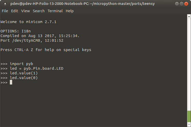
Introduction to MQTT

$
0
0

Introduction to MQTT a learn.sparkfun.com tutorial

Available online at: http://sfe.io/t827

Introduction

In this tutorial, you’ll learn everything you need to know about the MQTT messaging protocol, why you would want to use it, and how it’s implemented. In a nutshell, MQTT uses your existing Internet home network to send messages to your IoT devices and respond to those messages.

MQTT Nodes

Brief History

MQTT (Message Queuing Telemetry Transport) is a publish/subscribe messaging protocol that works on top of the TCP/IP protocol. The first version of the protocol was developed by Andy Stanford-Clark of IBM and Arlen Nipper of Cirrus Link in 1999. What makes MQTT faster than say sending HTTP requests with your IoT device is MQTT messages can be as small as 2 bytes, whereas HTTP requires headers which contains a lot of information that other devices might not care about. Also, if you have multiple devices waiting for a request with HTTP, you’ll need to send a POST action to each client. With MQTT, when a server receives information from one client, it will automatically distribute that information to each of the interested clients.

Required Materials

To follow along with the example in this tutorial, you will need the following pieces of hardware. You may not need everything though depending on what you have. Add it to your cart, read through the guide, and adjust the cart as necessary.

Optional Materials

Depending on your setup, you may also need the following.

Raspberry Pi LCD - 7" Touchscreen

Raspberry Pi LCD - 7" Touchscreen

LCD-13733
$64.95
36
microSD Card with Adapter - 16GB (Class 10)

microSD Card with Adapter - 16GB (Class 10)

COM-13833
$19.95
5
LCD Touchscreen HAT for Raspberry Pi - TFT 3.5in. (480x320)

LCD Touchscreen HAT for Raspberry Pi - TFT 3.5in. (480x320)

LCD-14776
$24.95
Multimedia Wireless Keyboard

Multimedia Wireless Keyboard

WIG-14271
$29.95
2

Suggested Reading

If you aren’t familiar with the following concepts, we recommend checking out these tutorials before continuing.

Raspberry Pi 3 Starter Kit Hookup Guide

Guide for getting going with the Raspberry Pi 3 Model B and Raspberry Pi 3 Model B+ starter kit.

ESP32 Thing Hookup Guide

An introduction to the ESP32 Thing's hardware features, and a primer on using the WiFi/Bluetooth system-on-chip in Arduino.

Getting Started with the Raspberry Pi Zero Wireless

Learn how to setup, configure and use the smallest Raspberry Pi yet, the Raspberry Pi Zero - Wireless.

How to Use Remote Desktop on the Raspberry Pi with VNC

Use RealVNC to connect to your Raspberry Pi to control the graphical desktop remotely across the network.

The Basics

Before you learn how to build a MQTT network, it will help to understand some of the jargon that’s used and how each piece fits together to create your network.

  • Broker - The broker is the server that distributes the information to the interested clients connected to the server.
  • Client - The device that connects to broker to send or receive information.
  • Topic - The name that the message is about. Clients publish, subscribe, or do both to a topic.
  • Publish - Clients that send information to the broker to distribute to interested clients based on the topic name.
  • Subscribe - Clients tell the broker which topic(s) they’re interested in. When a client subscribes to a topic, any message published to the broker is distributed to the subscribers of that topic. Clients can also unsubscribe to stop receiving messages from the broker about that topic.
  • QoS - Quality of Service. Each connection can specify a quality of service to the broker with an integer value ranging from 0-2. The QoS does not affect the handling of the TCP data transmissions, only between the MQTT clients. Note: In the examples later on, we’ll only be using QoS 0.
    • 0 specifies at most once, or once and only once without requiring an acknowledgment of delivery. This is often refered to as fire and forget.
    • 1 specifies at least once. The message is sent multiple times until an acknowledgment is received, known otherwise as acknowledged delivery.
    • 2 specifies exactly once. The sender and receiver clients use a two level handshake to ensure only one copy of the message is received, known as assured delivery.

How MQTT Works

As mentioned in the introduction, MQTT is a publish/subcribe messaging protocol. Clients will connect to the network, which can subscribe or publish to a topic. When a client publishes to a topic, the data is sent to the broker, which then is distributed to all the clients that are subscribed to that topic.

Topics are arranged in a directory-like structure. A topic might be “LivingRoom”, or “LivingRoom/Light” if you have multiple clients within that parent topic. The subscriber client will listen for incoming messages from the subscribed topic and react to what was published to that topic, such as “on” or “off”. Clients can subscribe to one topic and publish to another as well. If the client subscribes to “LivingRoom/Light”, it might also want to publish to another topic like “LivingRoom/Light/State” so that other clients can monitor the state of that light.

Now that we understand the theory of how MQTT works, lets build a quick and easy example with a Raspberry Pi and ESP32 Thing boards to see it working in action. We’ll start by setting up the broker and running a quick test to make sure it’s working correctly.

Setting Up the Broker

There’s a large collection of MQTT brokers available that can run from a remote server, or locally, both on your office machine as well as a dedicated computer like a Raspberry Pi. In the example used in this tutorial, we’re going to use a Raspberry Pi connected to our local network running a free and open-source broker called Mosquitto.

Setting up Mosquitto is simple, just open your terminal and enter:

language:bash
sudo apt-get install mosquitto -y

Once installed, we’ll want to make sure our broker is working by correctly by creating a test client from the Pi to listen to a topic. We’ll do this by installing the mosquitto clients:

language:bash
sudo apt-get install mosquitto mosquitto-clients -y

Once the clients have been installed, we’ll subscribe to the topic “test_topic” by entering:

language:bash
mosquitto_sub -t "test_topic"

We’re telling mosquitto we’d like to subscribe to a topic by entering mosquitto_sub, and that we’d like to subscribe to a topic denoted by -t with the name test_topic. Now every time we publish to test_topic, the message sent will appear in this window.

Because our terminal is listening for messages from our broker, we’ll need to open a second terminal window to publish messages to. Once opened, we’ll publish to test_topic with the following command:

language:bash
mosquitto_pub -t "test_topic" -m "HELLO WORLD!"

Just like before, we use the -t to denote the topic, but this time we’re adding a message to publish to the topic by using mosquitto_pub and using -m to denote the message to we’d like to publish. Once we hit enter, we should see our message appear on subscriber terminal window as shown below. You can replace that text with any string you’d like after -m to send your message to all of the clients subscribed to test_topic.

Hello World Example

Setting Up the Clients

Note: These example assumes you are using the latest version of the Arduino IDE on your desktop. If this is your first time using Arduino, please review our tutorial on installing the Arduino IDE. If you have not previously installed an Arduino library, please check out our installation guide.

Now that we know our broker is up and running it’s time to add our clients. We’re going to create two clients, the first will publish to the topic “room/light” with a message of “on” or “off” every time we push a button. The second client will subscribe to “room/light” and respond to the message by turning an LED on or off.

Publish Client - Switch

To create the switch, we’re going to use an ESP32 Thing. To get MQTT working on an ESP we’ll need to install a library called PubSubClient, which you can download from the link below:

ESP8266/32 MQTT PubSubClient Library (ZIP)

Once installed, open Arduino and paste in the code below. Just make sure to fill in the WiFi credentials for your router and the IP address of your Raspberry Pi broker. Once the ESP32 connects to the network, it waits for the button to be pressed. Once pushed, the ESP32 will publish the command to the topic “room/light”.

language:C
/******************************************************************************
MQTT_Switch_Example.ino
Example for controlling a light using an MQTT switch
by: Alex Wende, SparkFun Electronics

This sketch connects the ESP32 to a MQTT broker and subcribes to the topic
room/light. When the button is pressed, the client will toggle between
publishing "on" and "off".
******************************************************************************/

#include <WiFi.h>
#include <PubSubClient.h>

const char *ssid =  "-----";   // name of your WiFi network
const char *password =  "-----"; // password of the WiFi network

const byte SWITCH_PIN = 0;           // Pin to control the light with
const char *ID = "Example_Switch";  // Name of our device, must be unique
const char *TOPIC = "room/light";  // Topic to subcribe to

IPAddress broker(192,168,1,-); // IP address of your MQTT broker eg. 192.168.1.50
WiFiClient wclient;

PubSubClient client(wclient); // Setup MQTT client
bool state=0;

// Connect to WiFi network
void setup_wifi() {
  Serial.print("\nConnecting to ");
  Serial.println(ssid);

  WiFi.begin(ssid, password); // Connect to network

  while (WiFi.status() != WL_CONNECTED) { // Wait for connection
    delay(500);
    Serial.print(".");
  }

  Serial.println();
  Serial.println("WiFi connected");
  Serial.print("IP address: ");
  Serial.println(WiFi.localIP());
}

// Reconnect to client
void reconnect() {
  // Loop until we're reconnected
  while (!client.connected()) {
    Serial.print("Attempting MQTT connection...");
    // Attempt to connect
    if (client.connect(ID)) {
      Serial.println("connected");
      Serial.print("Publishing to: ");
      Serial.println(TOPIC);
      Serial.println('\n');

    } else {
      Serial.println(" try again in 5 seconds");
      // Wait 5 seconds before retrying
      delay(5000);
    }
  }
}

void setup() {
  Serial.begin(115200); // Start serial communication at 115200 baud
  pinMode(SWITCH_PIN,INPUT);  // Configure SWITCH_Pin as an input
  digitalWrite(SWITCH_PIN,HIGH);  // enable pull-up resistor (active low)
  delay(100);
  setup_wifi(); // Connect to network
  client.setServer(broker, 1883);
}

void loop() {
  if (!client.connected())  // Reconnect if connection is lost
  {
    reconnect();
  }
  client.loop();

  // if the switch is being pressed
  if(digitalRead(SWITCH_PIN) == 0) 
  {
    state = !state; //toggle state
    if(state == 1) // ON
    {
      client.publish(TOPIC, "on");
      Serial.println((String)TOPIC + " => on");
    }
    else // OFF
    {
      client.publish(TOPIC, "off");
      Serial.println((String)TOPIC + " => off");
    }

    while(digitalRead(SWITCH_PIN) == 0) // Wait for switch to be released
    {
      // Let the ESP handle some behind the scenes stuff if it needs to
      yield(); 
      delay(20);
    }
  }
}

Once the code has uploaded and the ESP32 has connected to the network, we want to test to make sure the broker is working correctly and we’re connected to the broker. To test this, from the terminal window of the Pi, we’re going to subscribe to “room/light” with the following command:

language:bash
mosquitto_sub -t "room/light"

Press on the ESP32's button that is connected on GPIO pin 0.

ESP32 switch location

Now when we press the button on the ESP32 connected to GPIO pin 0, we should see the on/off commands as shown below.

MQTT switch test from broker

Subscribe Client - Light

Now that the switch is connected to the broker, we need to connect a device that will react when a new message is sent to the topic. To do this, we’ll need another ESP32 and control the LED connected to pin 5 as shown below. Just like before, make sure to fill in the WiFi credentials and the IP address of your Raspberry Pi broker like you did in the previous example.

language:C
/******************************************************************************
MQTT_Light_Example.ino
Example for controlling a light using MQTT
by: Alex Wende, SparkFun Electronics

This sketch connects the ESP8266 to a MQTT broker and subcribes to the topic
room/light. When "on" is recieved, the pin LIGHT_PIN is toggled HIGH.
When "off" is recieved, the pin LIGHT_PIN is toggled LOW.
******************************************************************************/

#include <WiFi.h>
#include <PubSubClient.h>

const char *ssid = "-----";   // name of your WiFi network
const char *password = "-----"; // password of the WiFi network

const byte LIGHT_PIN = 5;           // Pin to control the light with
const char *ID = "Example_Light";  // Name of our device, must be unique
const char *TOPIC = "room/light";  // Topic to subcribe to
const char *STATE_TOPIC = "room/light/state";  // Topic to publish the light state to

IPAddress broker(192,168,1,-); // IP address of your MQTT broker eg. 192.168.1.50
WiFiClient wclient;

PubSubClient client(wclient); // Setup MQTT client

// Handle incomming messages from the broker
void callback(char* topic, byte* payload, unsigned int length) {
  String response;

  for (int i = 0; i < length; i++) {
    response += (char)payload[i];
  }
  Serial.print("Message arrived [");
  Serial.print(topic);
  Serial.print("] ");
  Serial.println(response);
  if(response == "on")  // Turn the light on
  {
    digitalWrite(LIGHT_PIN, HIGH);
    client.publish(STATE_TOPIC,"on");
  }
  else if(response == "off")  // Turn the light off
  {
    digitalWrite(LIGHT_PIN, LOW);
    client.publish(STATE_TOPIC,"off");
  }
}

// Connect to WiFi network
void setup_wifi() {
  Serial.print("\nConnecting to ");
  Serial.println(ssid);

  WiFi.begin(ssid, password); // Connect to network

  while (WiFi.status() != WL_CONNECTED) { // Wait for connection
    delay(500);
    Serial.print(".");
  }

  Serial.println();
  Serial.println("WiFi connected");
  Serial.print("IP address: ");
  Serial.println(WiFi.localIP());
}

// Reconnect to client
void reconnect() {
  // Loop until we're reconnected
  while (!client.connected()) {
    Serial.print("Attempting MQTT connection...");
    // Attempt to connect
    if(client.connect(ID)) {
      client.subscribe(TOPIC);
      Serial.println("connected");
      Serial.print("Subcribed to: ");
      Serial.println(TOPIC);
      Serial.println('\n');

    } else {
      Serial.println(" try again in 5 seconds");
      // Wait 5 seconds before retrying
      delay(5000);
    }
  }
}

void setup() {
  Serial.begin(115200); // Start serial communication at 115200 baud
  pinMode(LIGHT_PIN, OUTPUT); // Configure LIGHT_PIN as an output
  delay(100);
  setup_wifi(); // Connect to network
  client.setServer(broker, 1883);
  client.setCallback(callback);// Initialize the callback routine
}

void loop() {
  if (!client.connected())  // Reconnect if connection is lost
  {
    reconnect();
  }
  client.loop();
}

Find the built-in LED connected to GPIO pin 5 on the second ESP32 Thing.

ESP32 LED location

Once the second ESP32 connects to the network, it will automatically subscribe to “room/light” and when you push the button on the first ESP32, the built-in LED connected to GPIO pin 5 on the second ESP32 should respond and turn on and off. You can also go back and change the topic to “room/light2” or even just “room” to see how (or if) the device responds with the new topic.

On Off Example

Resources and Going Further

Hopefully, this tutorial has given you a starting point to integrate MQTT in your home automation project. Instead of turning a LED on or off, you could take it a step further and connect our IoT Power Relay to the ESP32 to control your AC powered devices.

IoT Power Relay

IoT Power Relay

COM-14236
$26.95
8

A tool not mentioned in this tutorial is Home Assistant. With Home Assistant you can control a wide array for commercial smart home devices, including MQTT. This means that with Home Assistant you can create your own MQTT devices that can easily control your existing smart home devices, but stay tuned for a tutorial about that in the future. In the mean time, there’s a blog post about MQTT and Home Assistant using an ESP8266 and Raspberry Pi which can be found here:


For more information about MQTT, check out some of the links below:

Need some inspiration for your next project? Check out some of these related tutorials:

SparkFun Blocks for Intel® Edison - Arduino Block

A quick overview of the features of the Arduino Block.

SparkFun Blocks for Intel® Edison - PWM

A quick overview of the features of the PWM Block.

Photon OLED Shield Hookup Guide

The Photon OLED Shield has everything you need to add a small yet crisp OLED screen to your Photon projects. This hookup guide will show you how to get started.

Blynk Board Project Guide

A series of Blynk projects you can set up on the Blynk Board without ever re-programming it.

learn.sparkfun.com | CC BY-SA 3.0 | SparkFun Electronics | Niwot, Colorado

Spectral Triad (AS7265x) Hookup Guide

$
0
0

Spectral Triad (AS7265x) Hookup Guide a learn.sparkfun.com tutorial

Available online at: http://sfe.io/t830

Introduction

The SparkFun Triad Spectroscopy Sensor is a powerful optical inspection sensor. Three AS7265x sensors are combined alongside a visible, UV, and IR LEDs to illuminate and test various surfaces for light spectroscopy.

SparkFun Triad Spectroscopy Sensor - AS7265x (Qwiic)

SparkFun Triad Spectroscopy Sensor - AS7265x (Qwiic)

SEN-15050
$64.95

AMS has combined the power of three sensors to cover the measurement of light from 410nm to 940nm in 18 individual bands.

18 Channel Spectral Response from the Datasheet

What Can You Do with Light Spectroscopy?

It’s an amazing field of study, and the SparkFun Triad brings what used to be prohibitively expensive equipment to the desktop. The AS7265x should not be confused with highly complex mass spectrometers, but the sensor array does give the user the ability to measure and characterize how different materials absorb and reflect 18 different frequencies of light.

Required Materials

To follow along with this hookup guide, you will need one of the following Qwiic shields to match your preference of microcontroller. You may not need everything though depending on what you have. Add it to your cart, read through the guide, and adjust the cart as necessary.

SparkFun Qwiic HAT for Raspberry Pi

SparkFun Qwiic HAT for Raspberry Pi

DEV-14459
$5.95
1
SparkFun Qwiic Shield for Arduino

SparkFun Qwiic Shield for Arduino

DEV-14352
$6.95
SparkFun Qwiic Shield for Photon

SparkFun Qwiic Shield for Photon

DEV-14477
$5.95

You will also need a Qwiic cable to connect the shield to your AS726X, choose a length that suits your needs.

Qwiic Cable - 100mm

Qwiic Cable - 100mm

PRT-14427
$1.50
Qwiic Cable - 500mm

Qwiic Cable - 500mm

PRT-14429
$1.95
Qwiic Cable - 200mm

Qwiic Cable - 200mm

PRT-14428
$1.50
Qwiic Cable - 50mm

Qwiic Cable - 50mm

PRT-14426
$0.95

Tools

Depending on your setup, you may need a soldering iron, solder, and general soldering accessories.

Solder Lead Free - 100-gram Spool

Solder Lead Free - 100-gram Spool

TOL-09325
$7.95
7
Weller WLC100 Soldering Station

Weller WLC100 Soldering Station

TOL-14228
$44.95

Suggested Reading

If you aren’t familiar with the Qwiic system, we recommend reading here for an overview.

Qwiic Connect System

We also recommend checking out these tutorials before continuing.

Light

Light is a useful tool for the electrical engineer. Understanding how light relates to electronics is a fundamental skill for many projects.

I2C

An introduction to I2C, one of the main embedded communications protocols in use today.

Hardware Overview

Sensors

The Triad is made up of three sensors; AS72651 (UV), AS72652 (VIS), and AS72653 (NIR). The AS72651 communicates with the x2 and x3 sensors over a dedicated I2C bus (the AS72651 is the master, the AS72652 and AS72653 are slaves). The AS72651 combines its sensor data with the data from the x2 and x3 sensors and exposes the datums to the user as a single array of registers. The SparkFun AS7265x Spectral Library makes it seamless to read any of the 18 frequencies of sensing.

Three sensors arranged in a circle

EEPROM

These sensors from AMS are interesting in that they ship without firmware. The firmware to drive the system is loaded onto a 4Mbit EEPROM that is read by the AS72651 at power on.

EEPROM containing the Spectral Triad firmware

LEDs / Bulbs

The Triad contains a 5700k white LED, a 405nm UV LED, and a 875nm IR LED mounted alongside the sensors. These LEDs were chosen to illuminate the target with the largest swath of visible and invisible light. The LEDs are individually enabled with software configurable drive current.

Three LEDs on Spectral Triad

The board also has multiple ways for you to illuminate the object that you are trying to measure for a more accurate spectroscopy reading. If you aren’t satisfied with the on-board, LEDs you can grab your own through hole incandescent bulbs. While you should find a bulb rated for 3.3V, a bulb rated for higher voltage, like 5V, will still work, but will not run as bright as it normally would with 5V. We’ve found that Mouser is a good place to look for these. If you are going to go that route and use your own bulb, be sure to disable the onboard LED by removing cutting the jumper to any ‘bulb’ footprint that is used. Cut the jumper next to each bulb footprint to disconnect the LED from the controller IC and solder in a bulb. We use the word ‘bulb’ to indicate any DC device (limited to 100mA max) but this signal pin could also be used to activate a larger MOSFET or control device to activate a much larger current device.

Jumper to cut to enable an external bulb

In addition to the illumination LEDs, there is a power LED and a status LED. The blue status LED indicates various states of the AS72651 sensor and can be disabled through the SparkFun library. The red power LED is provided to indicate the board is properly energized. If the red light is interfering with readings it can be disabled by cutting the neighboring jumper.

Jumper to cut to disable the power LED

I2C / Qwiic Interface

The Qwiic connectors provide a quick and easy way to connect the Triad over I2C. Alternatively, you can solder to the four pins: GND/3.3V/SDA/SCL. The sensors are 3.3V compatible so don’t use with a 5V Arduino Uno without proper conversion (use the Qwiic shield instead!). If you’re using a 3.3V development platform that doesn’t have a Qwiic connector, consider using the Qwiic Breadboard Cable.

Qwiic connectors and I2C jumper

Serial UART Interface

A serial interface is also available for those users who prefer using AT commands. Please refer to the AS7265x datasheet for a full list of commands. To enable the serial interface (and disable the I2C interface) you must modify two jumpers:

  1. The I2C jumper on the front of the board must be opened to remove the pull-up resistors from the TX and RX lines.
  2. The JP2 on the rear of the board must be closed with a solder jumper.

Serial Jumpers needing modification

Next, solder in a 6-pin right angle male header to the serial port.

Serial Pins and interface jumper on SparkFun Triad

The SparkFun Serial Basic connects directly to the Triad. The Serial Basic is set to 3.3V by default but if you’re using a different board, be sure it provides 3.3V on VCC and uses 3.3V logic signals.

Serial Basic connected to the serial connector on SparkFun Triad

The serial interface operates at 115200. To test the connection, open TeraTerm or your favorite terminal and connect to the Serial Basic. Send the command AT and look for an OK response. You’re all set! Check the AS7265x datasheet for a full list of AT commands.

Ok shown on the terminal window

AS7265x Arduino Library Overview

Note: This example assumes you are using the latest version of the Arduino IDE on your desktop. If this is your first time using Arduino, please review our tutorial on installing the Arduino IDE. If you have not previously installed an Arduino library, please check out our installation guide.

We’ve written an Arduino library to make reading the Triad a breeze. The easiest way to install the library is by searching SparkFun Spectral Triad with th Arduino library manager. You can also manually install the AS7265x library by downloading a zip:

Download the SparkFun AS7265X Library (ZIP)

Example 1 provided with the library demonstrates how to read all 18 channels. The higher examples demonstrate all the features available through the SparkFun library on the Spectral Triad:

  • Example 1 - Basic readings of all 18 channels
  • Example 2 - Controlling the onboard LEDs
  • Example 3 - Changing the many settings on the AS7652x
  • Example 4 - Output the raw sensor readings without calibration adjustment
  • Example 5 - Setting the sensor up for maximum read speed
  • Example 6 - Reading the temperatures of the three ICs
  • Example 7 - Reading the various hardware and firmware versions

Below are the various functions that can be called from the library. Most of these functions are demonstrated in the examples so we recommend you go through each example first.

  • boolean begin(TwoWire &wirePort = Wire);– Inits the sensor with default settings. Optional pass of wire port.
  • boolean isConnected();– Returns true if the sensor is detected on the I2C bus
  • boolean dataAvailable();– Returns true when data is available

  • uint8_t getTemperature(uint8_t deviceNumber = 0);– Get temp in C of the master IC

  • float getTemperatureAverage();– Get average of all three ICs

  • void takeMeasurements();– Tell sensor to take one-shot measurement

  • void takeMeasurementsWithBulb();– Take one-shot measurement with all three LEDs illuminated

  • float getCalibratedA(); to getCalibratedW();– Returns the various calibration data

  • uint16_t getA(); to getW();– Get the various raw readings

  • void enableIndicator();– Enable the blue status LED

  • void disableIndicator();– Disable the status LED. Handy when taking snesitive readings

  • void enableBulb(uint8_t device);– Turn on a given LED. 0 = White, 1 = IR, 2 = UV

  • void disableBulb(uint8_t device);– Turn off a given LED

  • void setGain(uint8_t gain);– 1 to 64x

  • void setMeasurementMode(uint8_t mode);– 4 channel, other 4 channel, 6 chan, or 6 chan one shot
  • void setIntegrationCycles(uint8_t cycleValue);– 2.78ms to 711ms

  • void setBulbCurrent(uint8_t current, uint8_t device);– 12.5mA to 100mA

  • void setIndicatorCurrent(uint8_t current);– 1 to 8mA

  • void enableInterrupt();– Enable the interrupt pin (active low)

  • void disableInterrupt();

  • void softReset();– Reset the device via software

  • uint8_t getDeviceType();– Should return 0x41

  • uint8_t getHardwareVersion();– Should return 0x40
  • uint8_t getMajorFirmwareVersion();– Returns the current firmware version, currently 0x0C
  • uint8_t getPatchFirmwareVersion();
  • uint8_t getBuildFirmwareVersion();

Taking A Banana Reading

Let’s get the Triad hooked up over Qwiic and begin illuminating a target and taking readings. Using a BlackBoard and a Qwiic Cable we’re able to attach to the Triad quickly and without soldering. Let’s open and use Example 2 from the library so that the Triad will take all 18 readings while illuminating the target.

Once you have a series of readings, plug them into your favorite graph utility. For our purposes, we like to use Google spreadsheets. You can paste the comma delimited output from the sketch directly into a sheet. Once there, drop the small menu down and select Split text to columns.

Splitting text to columns

You can access our data here. The graph of the 18 frequencies is pretty neat!

Graph of various items spectral response

Now that we have a baseline we can take a reading from an unknown thing (in this case, Uranium ore we had sitting around used for testing the Pocket Geiger Counter). Note that the distance to your sample will cause the amplitude of the readings to increase or decrease. We took our readings holding the Triad about 1 inch away from the surface of the target sample but a 3D printed shroud would remove background illumination and remove read distance variations.

As you can see the unknown sample follows closely to the Uranium Ore signature.

Reading an unknown sample

Science! The Triad is a fantastic tool that will have you looking around your house for interesting things to measure.

Resources and Going Further

Now that you’ve successfully got your Spectral Triad up and running, it’s time to incorporate it into your own project!

For more information, check out the resources below:

Need some inspiration for your next project? Check out some of these related tutorials:

SparkFun GPS Breakout - XA1110 (Qwiic) Hookup Guide

Figure out where in the world you are with the Qwiic SparkFun GPS Breakout - XA1110.

Qwiic Accelerometer (MMA8452Q) Hookup Guide

Freescale’s MMA8452Q is a smart, low-power, three-axis, capacitive micro-machined accelerometer with 12-bits of resolution. It’s perfect for any project that needs to sense orientation or motion. We’ve taken that accelerometer and stuck it on a Qwiic-Enabled breakout board to make interfacing with the tiny, QFN package a bit easier.

Qwiic Real Time Clock Module (RV-1805) Hookup Guide

Find out what time it is, even after the power's been out on your project for a while with the Qwiic Real Time Clock (RTC) module.
New!

TFMini - Micro LiDAR Module (Qwiic) Hookup Guide

The TFMini is a ToF (Time of Flight) LiDAR sensor capable of measuring the distance to an object as close as 30 cm and as far as 12 meters! The TFMini allows you to easily integrate LiDAR into applications traditionally reserved for smaller sensors such as the SHARP GP-series infrared rangefinders. With the added Qwiic feature, you can quickly connect to the sensor via I2C!

learn.sparkfun.com | CC BY-SA 3.0 | SparkFun Electronics | Niwot, Colorado
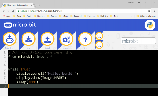
Viewing all 1122 articles
Browse latest View live