Quantcast
Channel: SparkFun Tutorials
Viewing all 1123 articles
Browse latest View live

TFMini - Micro LiDAR Module (Qwiic) Hookup Guide

$
0
0

TFMini - Micro LiDAR Module (Qwiic) Hookup Guide a learn.sparkfun.com tutorial

Available online at: http://sfe.io/t823

Introduction

SparkFun Qwiic Logo

Heads up! This tutorial is for the Qwiic enabled TFMini. Serial data is output via I2C. If you are using the TFMini that outputs serial data via UART [ SEN-14588 ], please refer to the TFMini - Micro LiDAR Module Hookup Guide.

The TFMini is a ToF (Time of Flight) LiDAR sensor capable of measuring the distance to an object as close as 30 cm and as far as 12 meters! The TFMini allows you to integrate LiDAR into applications traditionally reserved for smaller sensors such as the SHARP GP-series infrared rangefinders. With the added Qwiic feature, you can quickly connect to the sensor via I2C! In this tutorial, you will learn how to connect to the TFMini using an Arduino microcontroller with the Qwiic system.

TFMini - Micro LiDAR Module (Qwiic)

TFMini - Micro LiDAR Module (Qwiic)

SEN-14786
$39.95

Required Materials

To follow along with this tutorial, you will need the following materials. You may not need everything though depending on what you have. Add it to your cart, read through the guide, and adjust the cart as necessary.

Arduino Pro Mini 328 - 3.3V/8MHz

Arduino Pro Mini 328 - 3.3V/8MHz

DEV-11114
$9.95
44
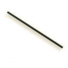
Break Away Headers - Straight

Break Away Headers - Straight

PRT-00116
$1.50
20
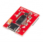
SparkFun Beefy 3 - FTDI Basic Breakout

SparkFun Beefy 3 - FTDI Basic Breakout

DEV-13746
$15.95
7
USB micro-B Cable - 6 Foot

USB micro-B Cable - 6 Foot

CAB-10215
$4.95
11
Qwiic Cable - Breadboard Jumper (4-pin)

Qwiic Cable - Breadboard Jumper (4-pin)

PRT-14425
$1.50
SparkFun Qwiic Adapter

SparkFun Qwiic Adapter

DEV-14495
$1.50
SparkX Logo

Tip: You could also use SparkX BlackBoard. It's basically a RedBoard with additional features. The board includes the same AP2112K 3.3V voltage regulator that is populated on the Beefy 3 and Qwiic connector on the board. This would reduce the amount of components and time soldering headers to the board. Additionally, a USB port can provide up to about 500mA so the TFMini may want to pull more power when auto ranging for longer distances.

Keep in mind that SparkX products are rapidly produced to bring you the most cutting edge technology as it becomes available. SparkX products are tested but come with no guarantees. Live technical support is not available for SparkX products.

SparkFun BlackBoard

SparkFun BlackBoard

SPX-14669
$14.95
3

Tools

Depending on your setup, you will need a soldering iron, solder, and general soldering accessories.

Solder Lead Free - 100-gram Spool

Solder Lead Free - 100-gram Spool

TOL-09325
$7.95
7
Weller WLC100 Soldering Station

Weller WLC100 Soldering Station

TOL-14228
$44.95

Suggested Reading

If you aren’t familiar with the Qwiic system, we recommend reading here for an overview.

Qwiic Connect System

We would also recommend taking a look at the following tutorials if you aren’t familiar with them.

Logic Levels

Learn the difference between 3.3V and 5V devices and logic levels.

I2C

An introduction to I2C, one of the main embedded communications protocols in use today.

Using the Arduino Pro Mini 3.3V

This tutorial is your guide to all things Arduino Pro Mini. It explains what it is, what it's not, and how to get started using it.

Hardware Overview

The sensor works by sending a modulated near-infrared light out. The light that is reflected from the object returns to the sensor’s receiver. The distance between the two can be converted using the sensor by calculating the time and phase difference. The distance measured may vary depending on the environment and the reflectivity of object.

Input Power

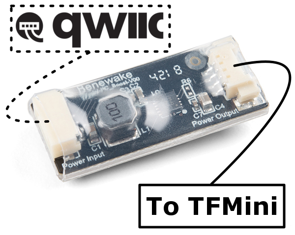
According to the datasheet (pg 1), the input voltage is 5V. In this tutorial, we will be using the included boost converter by applying a 3.3V input voltage from the Qwiic side to boost power to 5V on the TFMini side.

Benewake TFMini Boost Converter

Logic Levels

While the sensor can be powered at 5V, the I2C pins are only 3.3V logic. Make sure to use a logic level converter when reading the sensor with a 5V microcontroller.

Pinout

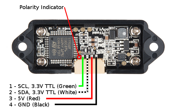
There is a marking next to the polarized connector to indicate the polarity as “J1” as indicated in the image below. This is useful when referencing sensor’s pinout. As opposed to the original TFMini, the green and white wires for the Qwiic enabled TFMini uses an I2C serial. The default address of the TFMini is 0x10.

TFMini Pinout

Pin NumberWire ColorQwiic TFMini PinoutWire Color
1GreenSCL (3.3V TTL)Yellow
2WhiteSDA (3.3V TTL)Blue
3Red5VRed
4BlackGNDBlack

Hardware Hookup

If you haven’t yet assembled your 3.3V Pro Mini, now would be the time to head on over to that tutorial to solder the header pins. Once soldered, connect the power and I2C pins between the Arduino Pro Mini 3.3V/8MHz and Qwiic adapter.

Arduino PinsQwiic Adapter PinsWire Color
A5 (SCL)SCL (3.3V TTL)Yellow
A4 (SDA)SDA (3.3V TTL)Blue
3.3V3.3VRed
GNDGNDBlack

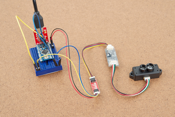
Then connect the Qwiic cable that was included in the Power Input side between the Qwiic adapter and the boost circuit. On the other side, insert the second cable that was included in the Power Output side between from the boost circuit to the TFMini. The connectors are different on each side of the boost converter so it should not be Finally, power the circuit up with a micro-B USB cable and the Beefy 3. The connection should look like the image below.

Qwiic Enabled TFMini with Beefy 3 and 3.3V Arduino Pro Mini

Tip: Looking to reduce the number of components? Try using the SparkX BlackBoard is an alternative to connecting to the Qwiic enabled TFMini. The trade off is that the BlackBoard is larger than the Arduino Pro Mini.

SparkX Hookup

Example Code

Note: This example assumes you are using the latest version of the Arduino IDE on your desktop. If this is your first time using Arduino, please review our tutorial on installing the Arduino IDE.

Grab a micro-B USB cable and connect the Arduino to your computer. Copy, paste, and upload the code below. Make sure to use the correct COM port and board selection.

language:c
/*
  LidarTest.ino
  Written in collaboration by Nate Seidle and Benewake

  Example sketch for the Qwiic Enabled TFMini
  (https://www.sparkfun.com/products/14786)
*/

#include <Wire.h>

uint16_t distance = 0; //distance
uint16_t strength = 0; // signal strength
uint8_t rangeType = 0; //range scale
/*Value range:
 00 (short distance)
 03 (intermediate distance)
 07 (long distance) */

boolean valid_data = false; //ignore invalid ranging data

const byte sensor1 = 0x10; //TFMini I2C Address

void setup()
{
  Wire.begin();

  Serial.begin(115200);
  Serial.println("TFMini I2C Test");
}

void loop()
{
  if (readDistance(sensor1) == true)
  {
    if (valid_data == true) {
      Serial.print("\tDist[");
      Serial.print(distance);
      Serial.print("]\tstrength[");
      Serial.print(strength);
      Serial.print("]\tmode[");
      Serial.print(rangeType);
      Serial.print("]");
      Serial.println();
    }
    else {
      //don't print invalid data
    }
  }
  else {
    Serial.println("Read fail");
  }
  delay(50); //Delay small amount between readings
}

//Write two bytes to a spot
boolean readDistance(uint8_t deviceAddress)
{
  Wire.beginTransmission(deviceAddress);
  Wire.write(0x01); //MSB
  Wire.write(0x02); //LSB
  Wire.write(7); //Data length: 7 bytes for distance data
  if (Wire.endTransmission(false) != 0) {
    return (false); //Sensor did not ACK
  }
  Wire.requestFrom(deviceAddress, (uint8_t)7); //Ask for 7 bytes

  if (Wire.available())
  {
    for (uint8_t x = 0 ; x < 7 ; x++)
    {
      uint8_t incoming = Wire.read();

      if (x == 0)
      {
        //Trigger done
        if (incoming == 0x00)
        {
          //Serial.print("Data not valid: ");//for debugging
          valid_data = false;
          //return(false);
        }
        else if (incoming == 0x01)
        {
          Serial.print("Data valid:     ");
          valid_data = true;
        }
      }
      else if (x == 2)
        distance = incoming; //LSB of the distance value "Dist_L"
      else if (x == 3)
        distance |= incoming << 8; //MSB of the distance value "Dist_H"
      else if (x == 4)
        strength = incoming; //LSB of signal strength value
      else if (x == 5)
        strength |= incoming << 8; //MSB of signal strength value
      else if (x == 6)
        rangeType = incoming; //range scale
    }
  }
  else
  {
    Serial.println("No wire data avail");
    return (false);
  }

  return (true);
}

Once uploaded, try moving an object in front of the sensor to test. In the example below, a third hand was used to hold the TFMini when detecting an object at a certain distance away from the sensor. Since the sensor is not able to detect an object when less than 11.8 inches (or 30cm = 0.3m) away, the object under test was placed at 20 inches and 30 inches.

Qwiic Enabled TFMini Reading an Object at 20 InchesQwiic Enabled TFMini Reading an Object at 30 Inches

Opening the serial monitor at 115200, you may see an output similar to the values printed below. Using a yard stick, the values responded as expected when moving an object between 30 inches and 20 inches. The Qwiic enabled TFMini indicated that the object was at an “intermediate distance”.

TFMini I2C Test
Data valid:         Dist[72]    strength[274]   mode[3]
Data valid:         Dist[72]    strength[275]   mode[3]
Data valid:         Dist[73]    strength[267]   mode[3]
Data valid:         Dist[72]    strength[265]   mode[3]
Data valid:         Dist[71]    strength[275]   mode[3]
Data valid:         Dist[70]    strength[284]   mode[3]
Data valid:         Dist[68]    strength[305]   mode[3]
Data valid:         Dist[67]    strength[311]   mode[3]
Data valid:         Dist[65]    strength[329]   mode[3]
Data valid:         Dist[65]    strength[335]   mode[3]
Data valid:         Dist[65]    strength[341]   mode[3]
Data valid:         Dist[65]    strength[361]   mode[3]
Data valid:         Dist[64]    strength[367]   mode[3]
Data valid:         Dist[64]    strength[383]   mode[3]
Data valid:         Dist[64]    strength[387]   mode[3]
Data valid:         Dist[64]    strength[386]   mode[3]
Data valid:         Dist[64]    strength[385]   mode[3]
Data valid:         Dist[64]    strength[384]   mode[3]
Data valid:         Dist[64]    strength[386]   mode[3]
Data valid:         Dist[64]    strength[394]   mode[3]
Data valid:         Dist[64]    strength[398]   mode[3]
Data valid:         Dist[64]    strength[400]   mode[3]
Data valid:         Dist[64]    strength[402]   mode[3]

Resources and Going Further

Now that you’ve successfully got your Quick enabled TFMini up and running, it’s time to incorporate it into your own project! For more on the TFMini, check out the links below:

Need some inspiration for your next project? Check out some of these related tutorials:

VL6180 Hookup Guide

Get started with your VL6180 based sensor or the VL6180 breakout board.

Building an Autonomous Vehicle: The Batmobile

Documenting a six-month project to race autonomous Power Wheels at the SparkFun Autonomous Vehicle Competition (AVC) in 2016.

LIDAR-Lite v3 Hookup Guide

A tutorial for connecting the Garmin LIDAR-Lite v3 or the LIDAR-Lite v3HP to an Arduino to measure distance.

Qwiic Distance Sensor (RFD77402) Hookup Guide

The RFD77402 uses an infrared VCSEL (Vertical Cavity Surface Emitting Laser) TOF (Time of Flight) module capable of millimeter precision distance readings up to 2 meters. It’s also part of SparkFun’s Qwiic system, so you won’t have to do any soldering to figure out how far away things are.

learn.sparkfun.com | CC BY-SA 3.0 | SparkFun Electronics | Niwot, Colorado


Getting Started with the SmartLED Shield for Teensy

$
0
0

Getting Started with the SmartLED Shield for Teensy a learn.sparkfun.com tutorial

Available online at: http://sfe.io/t831

Introduction

The PixelMatix SmartLED shield for Teensy makes it easy to connect to RGB LED matrix panels! The shield makes it easy to connect to the 16 pins required to drive the display, connects an external 5V supply to power the display and Teensy, and brings out the Teensy’s free signals to a convenient header.

SmartLED Shield V4 for Teensy

SmartLED Shield V4 for Teensy

DEV-15046
$19.95

In this tutorial, we will explore a some of the examples provided with the SmartLED shield using different RGB LED matrix panel sizes.

alt text

Required Materials

To follow along with this tutorial, you will need the following materials. You may not need everything though depending on what you have. Add it to your cart, read through the guide, and adjust the cart as necessary.

RGB LED Matrix Panel - 32x32

RGB LED Matrix Panel - 32x32

COM-14646
$44.95
RGB LED Matrix Panel - 32x64

RGB LED Matrix Panel - 32x64

COM-14718
$49.95
1
RGB LED Matrix Panel - 64x64

RGB LED Matrix Panel - 64x64

COM-14824
$79.95
Teensy 3.2

Teensy 3.2

DEV-13736
$19.80
62
Teensy 3.6 (Headers)

Teensy 3.6 (Headers)

DEV-14058
$33.25
3
Teensy 3.5

Teensy 3.5

DEV-14055
$24.95
1
Break Away Headers - Straight

Break Away Headers - Straight

PRT-00116
$1.50
20
microSD Card with Adapter - 16GB (Class 10)

microSD Card with Adapter - 16GB (Class 10)

COM-13833
$19.95
5
USB micro-B Cable - 6 Foot

USB micro-B Cable - 6 Foot

CAB-10215
$4.95
11
Teensy 3.5 (Headers)

Teensy 3.5 (Headers)

DEV-14056
$28.95
1
microSD USB Reader

microSD USB Reader

COM-13004
$4.95
8

Tools

Depending on your setup, you may need pliers, a soldering iron, solder, and general soldering accessories.

Solder Lead Free - 100-gram Spool

Solder Lead Free - 100-gram Spool

TOL-09325
$7.95
7
Weller WLC100 Soldering Station

Weller WLC100 Soldering Station

TOL-14228
$44.95
Needle Nose Pliers

Needle Nose Pliers

TOL-08793
$1.95
1

Suggested Reading

If you aren’t familiar with the following concepts, we recommend checking out these tutorials before continuing.

How to Power a Project

A tutorial to help figure out the power requirements of your project.

What is an Arduino?

What is this 'Arduino' thing anyway?

RGB Panel Hookup Guide

Make bright, colorful displays using the 32x16, 32x32, and 32x64 RGB LED matrix panels. This hookup guide shows how to hook up these panels and control them with an Arduino.

Getting Started with the Teensy

Basic intro to the Teensy line of products, with soldering and programming suggestions.

Hardware Overview

Teensy Footprint

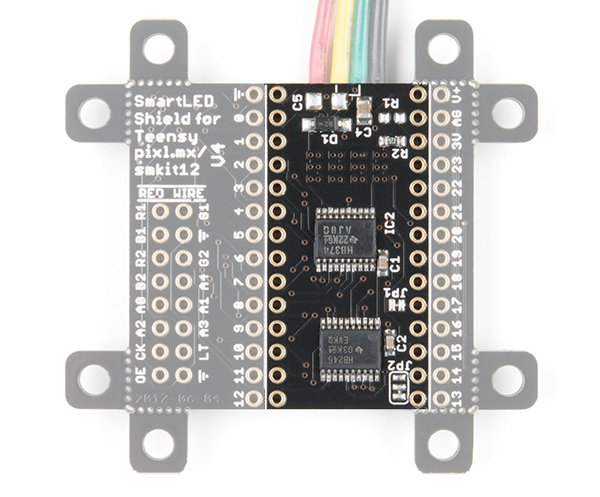
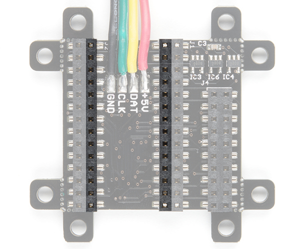
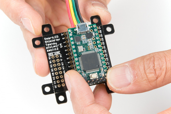
The SmartLED shield makes it easy to connect to RGB LED matrix panels. As opposed to wiring to 16 pins on the RGB LED matrix panel, you simply sandwich the shield between a Teensy and the IDC connector! The top of the board is where you would insert the Teensy populated with straight headers. The bottom of the shield includes female headers to make a secure connection.

Teensy Footprint (Top View)Teensy Footprint (Bottom View)

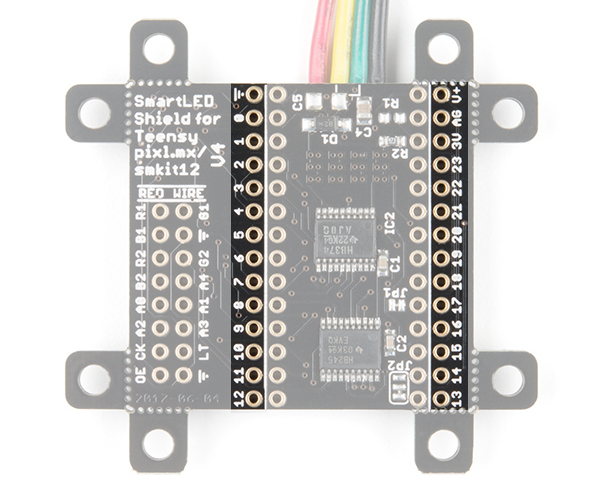
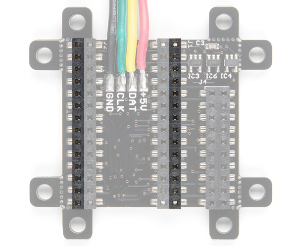
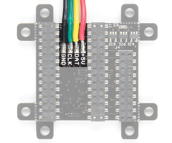
Adjacent to the Teensy footprint are additional pins that are broken out for easy access for prototyping or soldering wires directly to the shield.

Teensy Pins Broken Out (Top View)Teensy Pins Broken Out (Bottom View)

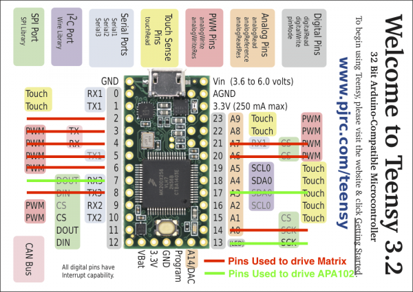
For more information about the reserved pins on the SmartLED matrix shield, check out the image below for the pins that are used to drive the RGB LED matrix panel and APA102 LEDs.

alt text

Image Courtesy of PJRC and PixelMatix

IDC Connector

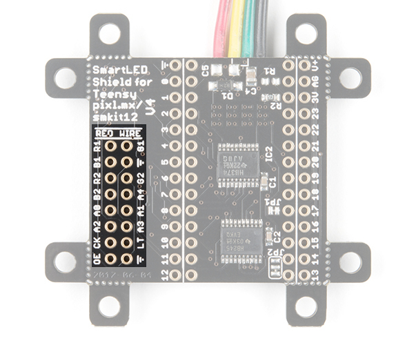
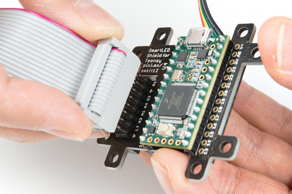
The shield breaks out the RGB LED matrix panel's IDC pins. Simply align the silkscreen with the panel's input and stack it on like a backpack. As an alternative, you can use an IDC cable and the included 2x8 long, centered header pins. Just make sure to align the cable’s red wire with the silkscreen labeled RED WIRE.

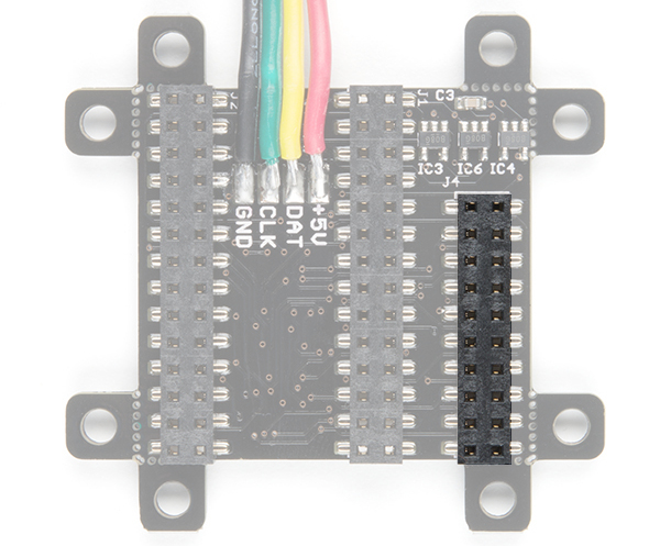
IDC Connector (Top View)IDC Connector (Bottom View)

APA102 LED

The shield includes additional 4-pin JST SM connector pair to connect a strip or matrix of APA102 LEDs from the SmartLED Shield.

alt text

Removable Mounting Holes

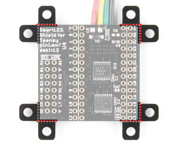
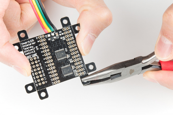
The shield includes mounting holes by each corner of the board. They can be used to to mount the shield when using the IDC cable. They are held to the rest of the board with mouse bites. Each of the mounting holes can be removed using pliers. The image below shows highlights the mounting holes with red lines along the mousebites.

alt text

ADDX Pins and Logic Levels

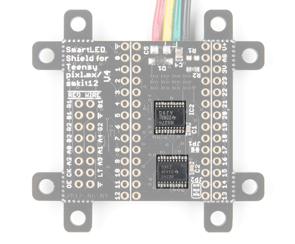
Certain panels may require 5V logic levels, which may not be enough with the Teensy's output pins. While you can try to wire all 16 pins from the Teensy to the IDC cable, it is not the most reliable connection. The panel may flicker or fail to display properly. The SmartLED shield was designed to include level shifting buffers to safely and reliably control the RGB LED matrix panels.

alt text

Hardware Assembly

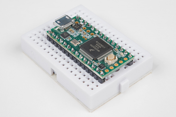
If you have not already, solder the male header pins on your Teensy before connecting. We will be using the 1x14 header pins on each side of a Teensy but you can also solder additional pins or or wires depending on your setup.

Soldered Headers on the Teensy 3.2

After soldering and removing the flux from a Teensy, stack the Teensy on the SmartLED shield. Make sure to face the USB connector in the same direction as the 4-pin JST SM connector.

alt text

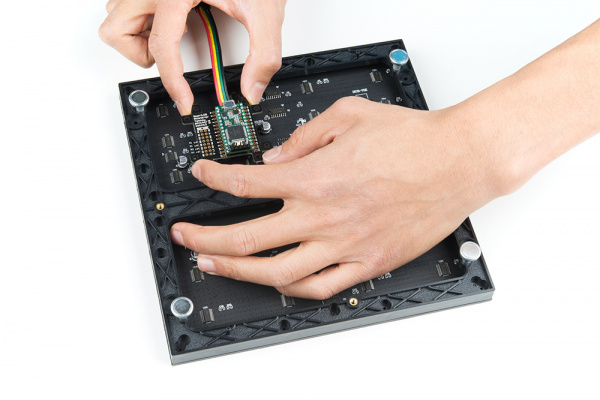
Align the IDC connector breakout on the SmartLED shield with the IDC connector on your RGB LED Matrix Panel. The location of the IDC connector depends on the manufacturer of the panel but usually it will be located on the left side relative to the arrows pointing up and toward the right.

alt text

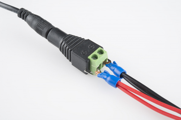
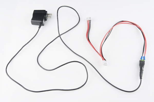
If you have not already, attach a 5V power supply to your RGB LED matrix panel's power cable by using the power supply in conjunction with a female barrel jack adapter and screwdriver to get a quick and dirty connection between the spade and barrel jack.

Spade connected to barrel jack adapter

The connection should look like the image below.

Wall adapter connected via barrel jack adapter

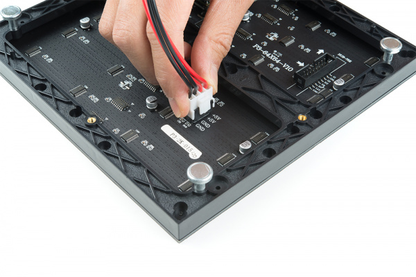
Then slide the polarized power cable for the RGB matrix panel into its respective mating connector. The red wires should be connected to the 5V pins while the black wires should be connected to the GND pins.

alt text

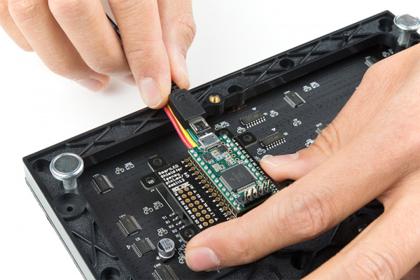
For the scope of this tutorial, we will connect 5V USB power directly to the Teensy's USB connector. This is separate from the power supply that is powering the RGB LED matrix panel. Depending on your setup, you can use the same power supply that the RGB LED matrix panel is using by connecting to either the Teensy's V+ and GND pins or the APA102 JST SM connector. Just make sure that the voltage is regulated at 5V.

alt text

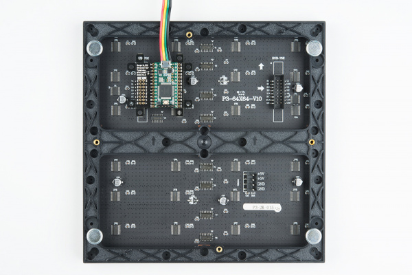
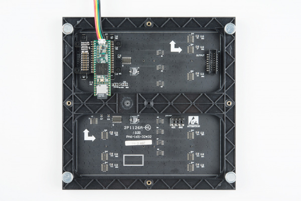
Once connected, the back of your RGB LED matrix panel should look similar to the images below. On the left, a Teensy 3.2 was connected to a 64x64 panel with 3mm pitched LEDs. On the right, a Teensy 3.6 was used for a 32x32 with 6mm pitched LEDs.

Alternative Connections

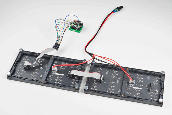
There is an option to daisy chain the panels together if you are within the limits of the SmartLED library. Simply connect the output from the first panel to the input of the second panel. Make sure to provide power to each panel through the 4-pin polarized connector.

alt text

As explained earlier, you can try to wire all 16 pins from the Teensy to the panel's IDC cable. It is not the most reliable connection. There is a higher probability of wiring incorrectly or a connection becoming loose. For more information on trying the connection, check out the table below. This connection is not possible when wiring to a 64x64 panel due to the extra 5th addressing pin.

Panel Pin Label Cable Connector Pin # Teensy Notes
R0 1 2 Red Data
(columns 1-16)
G0 2 5 Green Data
(columns 1-16)
B0 3 6 Blue Data
(columns 1-16)
GND 4 GND Ground
R1 5 21 Red Data
(columns 17-32)
G1 6 8 Green Data
(columns 17-32)
B1 7 20 Blue Data
(columns 17-32)
GND 8 GND Ground
A 9 15 Demux Input A0
B 10 22 Demux Input A1
C 11 23 Demux Input A2
D 12 9 Demux Input E1, E3 (32x32 panels only)
CLK 13 14 LED Drivers' Clock
STB 14 3, 8 LED Drivers' Latch
OE 15 4 LED Drivers' Output Enable
GND 16 GND Ground

Software Installation

Note: This example assumes you are using the latest version of the Arduino IDE on your desktop. If this is your first time using Arduino, please review our tutorial on installing the Arduino IDE. If you have not previously installed an Arduino library, please check out our installation guide.

Teensyduino Add-On

If you haven’t used Teensy before, you’ll need to download and install the extension for the Arduino IDE called Teensyduino from PJRC. This will also install the drivers for the board. Follow the instructions on installing the add-on before continuing on.

PJRC: Teensyduino Download Page

Install Library

Louis Beaudoin has written an amazing library to control the RGB LED matrix panels. You can obtain these libraries through the Arduino Library Manager. Search for SmartMatrix3 and you should be able to install the latest version. If you prefer downloading the libraries manually you can also grab them from the GitHub repository:

GitHub Pixelmatix - SmartMatrix (ZIP)

Library Overview

For an overview of the functions, check out documentation in the MIGRATION.md file from the GitHub repository.

GitHubPixelmatix Docs - SmartMatrix Library Overview

Example

There are a few examples from the SmartMatrix library for the SmartLED Shield. For the scope of the tutorial, we will be highlighting three of the examples.

Feature Demo!

Let's start with the feature demo. After installing the library, click File>Examples>SmartMatrix3>FeatureDemo.ino in the Arduino IDE. Once open, there are a minimum of 4 lines to modify to get the example working with your matrix panel:

  • uncomment line “#include <SmartLEDShieldV4.h>” if you are using the shield
  • adjust kMatrixWidth to the width of your panel
  • adjust kMatrixHeight to the height of your panel
  • adjust kPanelType based on the scan rate of your panel from line 34 in SmartMatrix3.h

The comments in the example code indicate that he known working width are: “32, 64, 96, 128”. As for the height, the known working sizes are: 16, 32, 48, 64. If you dig into the library, the known working scan rates are 1/8, 1/16, and 1/32.

64x64 Panel with 1/32 Scan Rate

Let's try modifying the example code to work with the 64x64 panel with a 1/32 scan rate. The SmartLED shield is required to address the extra 5th ADDX pin on the IDC connector. Simply:

  • uncomment line “#include <SmartLEDShieldV4.h>” by removing the “//
  • adjust kMatrixWidth to the width of your panel by replacing 32 with 64
  • adjust kMatrixHeight to the height of your panel by replacing 32 with 64
  • adjust kPanelType by replacing SMARTMATRIX_HUB75_32ROW_MOD16SCAN with SMARTMATRIX_HUB75_64ROW_MOD32SCAN from line 34 in SmartMatrix3.h

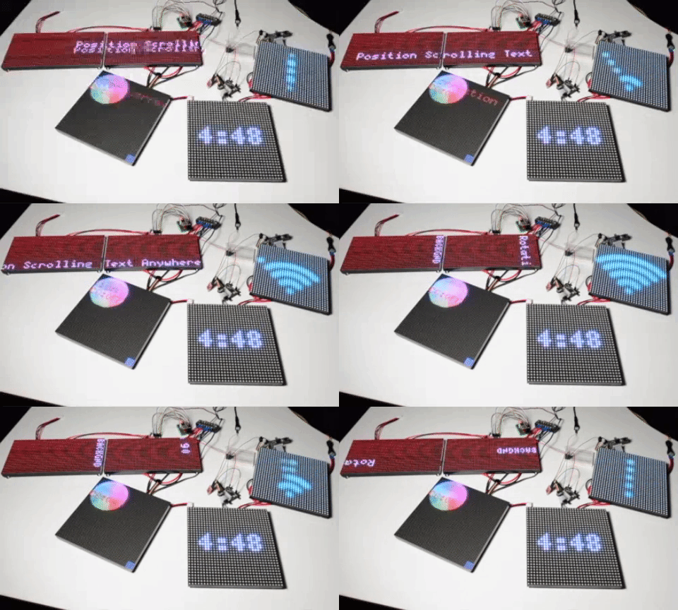
When the changes are completed, select the Teensy board definition with the associated COM port and click upload. You should see the feature demo running. This includes scrolling text, animations, shapes being drawn, brightness changing, and refresh rate changing.

alt text

Resources and Going Further

Now that you’ve successfully got your SmartLED shield for Teensy up and running, it’s time to incorporate it into your own project!

For more information, check out the resources below:

Need some inspiration for your next project? Check out some of these related tutorials:

RGB Panel Jumbotron

This tutorial will show you how to combine a webcam, a 32x32 RGB LED panel, and a Teensy 3.1 to stream video from the webcam, pixelate it, and display it on the LED panel - LIVE.

Or check out the Aurora project.


learn.sparkfun.com | CC BY-SA 3.0 | SparkFun Electronics | Niwot, Colorado

Introduction to DMX

$
0
0

Introduction to DMX a learn.sparkfun.com tutorial

Available online at: http://sfe.io/t836

Introduction

In this tutorial, we’ll cover DMX512 (Digital Multiplex with 512 pieces of information). Originally intended as a way to standardize communication among lighting dimmers, DMX512 has been adapted to control a variety of stage lighting and effects such as intelligent lights, gobos, lasers, and fog machines. DMX512 is even used in many architectural lighting scenarios (I’m looking at you Las Vegas). In this tutorial, we’ll go over what there is to know about how and when to implement DMX.

History

DMX512 was created in 1986 by an engineering commission for USITT (United States Institute for Theater Technology) as a way to control dimming channels on lights. In 1998, the ESTA began work in getting DMX to the point where it could be approved by ANSI and in 2004, DMX-512A was ANSI approved as the “Asynchronous Serial Digital Data Transmission Standard for Controlling Lighting Equipment and Accessories.”

Suggested Reading

Check out this tutorial on serial communication if you aren’t familiar with serial communication.

Serial Communication

Asynchronous serial communication concepts: packets, signal levels, baud rates, UARTs and more!

Basic Definitions

  • Fixture/Slave: Any object that takes DMX input. Receives a full DMX packet, picks out and listens data relevant to itself (intelligent lights, gobos, lasers, and fog machines). Most Fixtures have an output channel that is simply a copy of the input.
  • Universe: A Universe consists of a set of fixtures all strung together reading the same data. A Universe contains 512 bytes of information, so the amount of fixtures in a universe will depend on how many bytes of data are needed to address each fixture.
  • Controller: Creates and sends DMX data to one or more Universes. Usually, this a large board with many knobs and sliders, however, a simple PC can be used as a DMX controller.

Hardware Layer

DMX512 is typically employed over relatively long distances due to the distance between the lighting booth and stage. The further a signal is sent, the longer distance you have available to pick up stray electromagnetic interference from the surrounding area. Combine this with the fact that DMX is usually used in electrically noisy environments and we have to settle on a solution that is relatively noise free, so DMX employs RS-485.

Signals like this are interpreted by reading the difference between one wire with the data (D+), and another wire with the inverse of the data (D-). Since we are reading the difference, we call this a differential signal. Differential signals like RS485 pick up noise almost equally along the two signal lines, this keeps the difference between the two signals the same. Since we read the difference between the two signals, it’s easy to communicate over long distances (The DMX standard recommends a maximum run of a thousand feet, although RS-485 is rated for 4,000 feet).

DMX data is typically transferred over an XLR-5 cable, although occasionally, DMX capable XLR-3 cables are also used. RS-485 only requires 3 lines, ground, Data+, and Data-; and in many applications, this is all that was used. However, an additional pair of data lines was added to allow for future growth, requiring the XLR-5 cable. These connectors and their pinouts are shown below.

XLR-3

XLR-3

XLR-5

XLR-5

PinXLR-3XLR-5
1CommonCommon
2Data 1 -Data 1 -
3Data 1 +Data 1 +
4N/AData 2 -
5N/AData 2 +

An issue that arises with the communication over distance is that DMX devices are usually powered far away from each other. These distances this can result in ground loops; differences in voltage between the ground potentials of two devices which, if high enough, results in current flow between devices. Due to this distance, the DMX512 standard also calls for opto-isolation between the microcontroller and DMX portions of the circuit on a DMX fixture.

It is also wise to fit a 120&ohm; termination resistor between the two data lines at the extreme end of the chain of DMX devices to prevent signal reflection. Some devices have a switch, some will suggest you plug in an XLR cable with a terminating resistor attached, while others simply won’t have one at all. An unterminated DMX line can cause flickering in your whole Universe, so be sure the line is terminated.

Packet Structure

DMX data is asynchronous serial data sent at 250 kbit/s with 2 stop bits and no parity. This means that each clock pulse or bit sent takes 4 µs. The packet is structured beginning with a long BREAK where all data sent is low. This is followed by a Mark After Break or MAB, which is a short period high. There is then a Start Code (SC), consisting of an 11 bit serial frame (1 low bit, the 8 bit data byte, and 2 high bits) in which the data sent is 0x00. The Start Code can also contain different data to signify what type of DMX data is contained within the packet; 0x17 signifies a text packet, 0xCC for a Remote Device Management packet (more on this later), 0xCF is a system information packet, all sorts of start codes are used to signify different types of data. The Start Code is then followed by up to 512 frames of the same structure, each called a SLOT, containing all of the DMX data (RGB values, CMY values, servo position, fog machine pressure, etc…). There is an optional Mark Time Between Frames, (MTBF) which can be up to a second high between each frame. Once the data frames have finished sending, there is another Mark Time Between Packets (MTBP) of up to a second. However, these are rarely used to maintain frame rate. The table below shows the timings and common abbreviations of each of these parts of a DMX packet.

PacketAbbr.Clock PulsesTiming
BreakBREAK2288 µs
Mark After BreakMAB28 µs
Start CodeSC1144 µs
Mark Time Between FramesMTBFX0-1 s
SlotSLOT1144 µs
Mark Time Between PacketsMTBPX0-1 s
Full DMX512 PacketN/A56670.023 ms

Note the time it takes for a full DMX packet to be transmitted (23 ms). Inverting this gives us a maximum frame rate of 44 Hz.

Decoding the Data

The previously discussed DMX packet is then sent down the string of devices, but how should a device know which slot of the packet it needs to listen to? DMX fixtures usually have a DIP switch located somewhere to select the starting data slot to listen to, then the fixture will listen for it’s fixed number of slots. For example, a simple RGB dimmer will take up 3 slots, one for each color, so if we set the starting slot to 12, it will listen to the data on slots 12, 13, and 14. DMX fixtures should increment their slot counter on the second stop bit, so when the next frame begins, the microprocessor will know which slot the data should be in. The counter should then reset every time a break and mark are detected. This means that a DMX packet doesn’t have to have all 512 data slots, as the counter can reset at variable intervals. However, this limits the amount of fixtures occupying a single Universe depending on how many slots each fixture needs.

Remote Device Management (RDM)

Remote Device Management, or RDM for short is a way to use DMX to get information back about lighting fixtures. The protocol sends out a DMX512 packet with an RDM start code (0xCC) followed by a unique ID of the fixture it is attempting to communicate with. The controller will then release the data lines, and wait for a response. After a certain amount of time, the controller will assume it’s failed and may try again. RDM is a great way to find out exactly what each fixture is capable of if you’re just plugging into an unknown Universe.

Resources and Going Further

Hopefully this guide has allowed you to get your super cool and wacky light fixture communicating over DMX, making it easy for anyone to control it without having to tediously code their own lighting patterns. Check out these implementations of DMX if you’re looking for a little inspiration.


learn.sparkfun.com | CC BY-SA 3.0 | SparkFun Electronics | Niwot, Colorado

SparkFun LoRa Gateway 1-Channel Hookup Guide

$
0
0

SparkFun LoRa Gateway 1-Channel Hookup Guide a learn.sparkfun.com tutorial

Available online at: http://sfe.io/t826

Introduction

So you’ve designed an automatic shepherding robot but you still have to go out to the field to make sure it is working? Worry no more, you can use long-range radio to keep tabs on that ‘bot through the internet of things! All you need is an interpreter to speak the language, and the LoRa Gateway 1-Channel does just that.

SparkFun LoRa Gateway - 1-Channel (ESP32)

SparkFun LoRa Gateway - 1-Channel (ESP32)

WRL-15006
$34.95

The LoRa Gateway 1-Channel is a monster 3-network capable device thanks to an ESP32 module and a RFM95W LoRa modem. The RFM95W handles the 915 MHz band while the ESP32 takes care of bluetooth and WiFi. One of the ideal uses is to convert LoRa (Long Range) radio messages into data packets that you can access via the web, but of course the flexibility it offers can be put to many more uses!

This guide will go over the hardware on the board, how to program it in Arduino, how to create a single channel LoRa gateway, and finally how to create a LoRa device on The Things Network.

Required Materials

The LoRa Gateway 1-Channel can act as either a gateway or a device, but not both at the same time. To really be sure that your setup works as expected you should have another LoRa device to listen to, and/or another LoRa gateway to transmit to. The good news is that the LoRa Gateway 1-Channel can act as both so if you have two then you’re all set.

If you only have one LoRa 1-Channel gateway then you can choose one of these products to test it:

SparkFun Pro RF - LoRa, 915MHz (SAMD21)

SparkFun Pro RF - LoRa, 915MHz (SAMD21)

WRL-14916
$29.95
1
SparkX SAMD21 Pro RF 1W

SparkX SAMD21 Pro RF 1W

SPX-15034
$49.95
LoRa Raspberry Pi Gateway with Enclosure

LoRa Raspberry Pi Gateway with Enclosure

WRL-14869
$249.95
SparkFun LoRa Gateway - 1-Channel (ESP32)

SparkFun LoRa Gateway - 1-Channel (ESP32)

WRL-15006
$34.95

To program the LoRa Gateway 1-Channel you will need a micro-B USB cable and a computer with the Arduino IDE installed. If you want to make a permanent installation away from your computer then consider powering it with a USB wall adapter or USB battery pack.

Tools

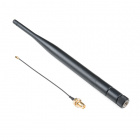
To use the 915 MHz radio on the gateway you will need an antenna - for which you have two choices. You may cut a length of solid-core wire to approx 3" or use a 915 MHz antenna with a U.FL connector. If you choose the wire route then you will also need a soldering iron and tools to attach your antenna to the board.

Weller WLC100 Soldering Station

Weller WLC100 Soldering Station

TOL-14228
$44.95
Interface Cable RP-SMA to U.FL

Interface Cable RP-SMA to U.FL

WRL-00662
$4.95
1
Pycom LoRa and Sigfox Antenna Kit - 915MHz

Pycom LoRa and Sigfox Antenna Kit - 915MHz

WRL-14676
$11.95
915MHz LoRa Antenna RP-SMA - 1/4 Wave 2dBi

915MHz LoRa Antenna RP-SMA - 1/4 Wave 2dBi

WRL-14875
$7.95

Suggested Reading

If you aren’t familiar with the following concepts, we recommend checking out these tutorials before continuing.

How to Solder: Through-Hole Soldering

This tutorial covers everything you need to know about through-hole soldering.

Installing Arduino IDE

A step-by-step guide to installing and testing the Arduino software on Windows, Mac, and Linux.

Serial Terminal Basics

This tutorial will show you how to communicate with your serial devices using a variety of terminal emulator applications.

Hardware Overview

The LoRa Gateway 1-Channel is chock full of functionality:

  • ESP32-WROOM-32 module
  • WiFi, BT+BLE microcontroller
  • Integrated PCB antenna
  • Hope RFM95W LoRa modem
  • Frequency range: 868/915 MHz
  • Spread factor: 6-12
  • SPI control interface
  • U.FL antenna connector for LoRa radio
  • Reset and ESP32 pin0 buttons
  • 14 GPIO ESP32 pin-breakouts
  • Power and user LEDs
  • Qwiic connector
  • CH340C USB-to-Serial interface
  • Micro-B USB connector for power and programming
  • Voltage input range: 3.3V-6V max

ESP32

The brains of the gateway is an ESP32-WROOM-32 module, shown below. It has all the same features as the SparkFun ESP32 Thing rolled up into one sweet little package. WiFi, Bluetooth, 240 MHz processing speed, and a bunch of I/O pins make it a great foundation for the gateway.

ESP32 Wroom module on ESP LoRa 1-Channel Gateway

RFM95W

Every LoRa gateway needs to speak the Chirp Spread Spectrum (CSS) radio language and the RFM95W module does just that in the 915 MHz centered ISM band. The limitation on this device is it can only listen to one LoRa channel at a time, unlike full multi-channel LoRa gateways.

RFM95 Radio Module on ESP LoRa 1-Channel Gateway

Antenna Connections

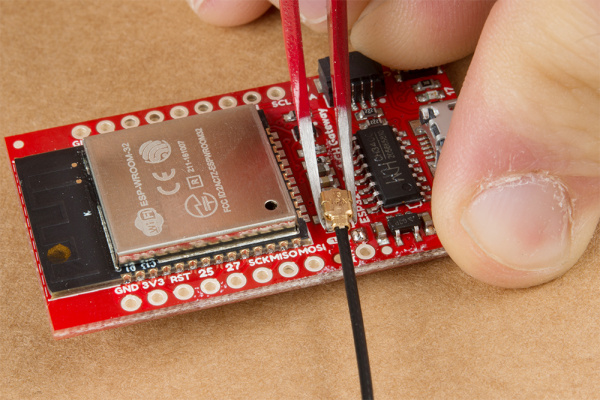
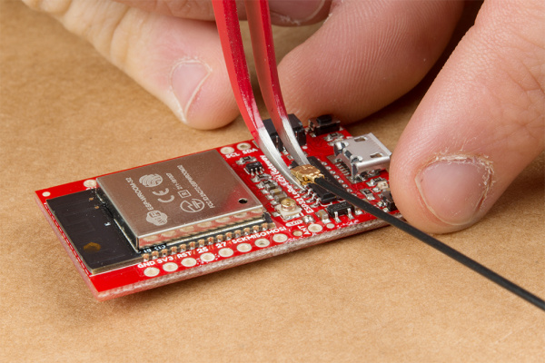
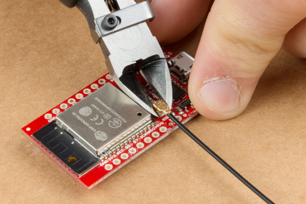
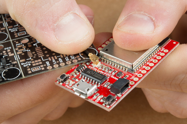
The LoRa Gateway 1-Channel sports both a through-hole antenna connection with strain relief as well as a U.FL connection for higher performance antennas.

Antenna connections on ESP LoRa 1-Channel Gateway

User Buttons, LEDs, and USB

On the bottom left side of the board you will find the power led and the reset button. Opposing are a button connected to pin 0 and an led connected to pin 17. The buttons exist to force the ESP32 into programming mode in case the automatic process by the CH340C USB-serial bridge chip fails, but after that you can use button 0 as an active-low input for your sketch. The ESP also uses the USB-serial bridge as the default serial port so there’s nothing else you need to connect to your computer.

User buttons, leds, and USB connection on ESP LoRa 1-Channel Gateway

Qwiic Connector

The default I2C lines of the ESP32 are broken out to both PTH pads and the super-convenient Qwiic connector. This means you can easily add peripherals to your gateway or sensors to your LoRa device!

Qwiic I2C connector on ESP LoRa 1-Channel Gateway

IO Pins

For anything other than I2C you can use the SPI lines and/or 7 GPIO pins which are all broken out to PTH pads around the board.

General purpose I/O Pins on ESP LoRa 1-Channel Gateway

Programming the ESP32 With Arduino

Note: This example assumes you are using the latest version of the Arduino IDE on your desktop. If this is your first time using Arduino, please review our tutorial on installing the Arduino IDE. If you have not previously installed an Arduino library, please check out our installation guide.

We will be using the Arduino IDE to upload new code to the Gateway. To get everything working the way it oughtta you’ll have to install the ESP32 Arduino core - a set of tools and code that translates Arduino code to something that the ESP32 understands. You can also make life a little bit easier by installing a custom board definition for the LoRa Gateway 1-Channel.

Install ESP32 Arduino Core

The ESP32’s relationship with Arduino is growing and now it is very easy to install the core - the Arduino IDE can handle it nearly on its own. All you need to do is make sure you have Arduino IDE version 1.8 or later, then paste

language:c
https://dl.espressif.com/dl/package_esp32_index.json

into the Additional Board Manager URLs field of the preferences window, like this:

Adding ESP Board Manager JSON File to Arduino

Hard time seeing? Click on the image for a closer look!

Now accept the changes and restart the Arduino IDE. Next open the Board Manager from the top of Tools > Board and search for ESP32. Click “Install” on the search result, after a little while the text besides the name should change to “Installed.” Re-start the IDE for good measure.

Install the LoRa Gateway 1-Channel Board Definition

Download the variant file zip folder and extract it into the location of your ESP32 Arduino core installation. If you used the board manager as shown above then the file path is likely very similar the following:

Windows:

  • C:\Users\<user.name>\AppData\Local\Arduino15\packages\esp32\hardware\esp32\1.0.0\variants.

Mac:

  • /Users/<user.name>/Library/Arduino15/packages/esp32/hardware/esp32/1.0.0/variants

If you see other variant folders in the folder listed above, it’s a good indication that you’re in the right place.

Download the SparkFun LoRa Gateway 1-Channel ESP32 variant definition (ZIP)

Note: If you cannot find your "AppData" folder, it may be hidden. For windows, click on the "View" tab of your explorer window and check the "Hidden Items" checkbox as seen here:

To make sure that Arduino knows to look for the variant that you just installed you will need to paste the following text into the boards.txt file in the ~\esp32\1.0.0 folder. Technically you can paste the text in anywhere but to maintain readability, do it before a long string of ‘#’s. I prefer to put my definitions at the top so that they appear first in the list of boards in the boards manager.

language:c
##############################################################

sparkfun_lora_gateway_1-channel.name=SparkFun LoRa Gateway 1-Channel

sparkfun_lora_gateway_1-channel.upload.tool=esptool
sparkfun_lora_gateway_1-channel.upload.maximum_size=1310720
sparkfun_lora_gateway_1-channel.upload.maximum_data_size=294912
sparkfun_lora_gateway_1-channel.upload.wait_for_upload_port=true

sparkfun_lora_gateway_1-channel.serial.disableDTR=true
sparkfun_lora_gateway_1-channel.serial.disableRTS=true

sparkfun_lora_gateway_1-channel.build.mcu=esp32
sparkfun_lora_gateway_1-channel.build.core=esp32
sparkfun_lora_gateway_1-channel.build.variant=sparkfun_lora_gateway_1-channel
sparkfun_lora_gateway_1-channel.build.board=ESP32_DEV

sparkfun_lora_gateway_1-channel.build.f_cpu=240000000L
sparkfun_lora_gateway_1-channel.build.flash_size=4MB
sparkfun_lora_gateway_1-channel.build.flash_freq=40m
sparkfun_lora_gateway_1-channel.build.flash_mode=dio
sparkfun_lora_gateway_1-channel.build.boot=dio
sparkfun_lora_gateway_1-channel.build.partitions=default

sparkfun_lora_gateway_1-channel.menu.PartitionScheme.default=Default
sparkfun_lora_gateway_1-channel.menu.PartitionScheme.default.build.partitions=default
sparkfun_lora_gateway_1-channel.menu.PartitionScheme.minimal=Minimal (2MB FLASH)
sparkfun_lora_gateway_1-channel.menu.PartitionScheme.minimal.build.partitions=minimal
sparkfun_lora_gateway_1-channel.menu.PartitionScheme.no_ota=No OTA (Large APP)
sparkfun_lora_gateway_1-channel.menu.PartitionScheme.no_ota.build.partitions=no_ota
sparkfun_lora_gateway_1-channel.menu.PartitionScheme.no_ota.upload.maximum_size=2097152
sparkfun_lora_gateway_1-channel.menu.PartitionScheme.min_spiffs=Minimal SPIFFS (Large APPS with OTA)
sparkfun_lora_gateway_1-channel.menu.PartitionScheme.min_spiffs.build.partitions=min_spiffs
sparkfun_lora_gateway_1-channel.menu.PartitionScheme.min_spiffs.upload.maximum_size=1966080

sparkfun_lora_gateway_1-channel.menu.FlashMode.qio=QIO
sparkfun_lora_gateway_1-channel.menu.FlashMode.qio.build.flash_mode=dio
sparkfun_lora_gateway_1-channel.menu.FlashMode.qio.build.boot=qio
sparkfun_lora_gateway_1-channel.menu.FlashMode.dio=DIO
sparkfun_lora_gateway_1-channel.menu.FlashMode.dio.build.flash_mode=dio
sparkfun_lora_gateway_1-channel.menu.FlashMode.dio.build.boot=dio
sparkfun_lora_gateway_1-channel.menu.FlashMode.qout=QOUT
sparkfun_lora_gateway_1-channel.menu.FlashMode.qout.build.flash_mode=dout
sparkfun_lora_gateway_1-channel.menu.FlashMode.qout.build.boot=qout
sparkfun_lora_gateway_1-channel.menu.FlashMode.dout=DOUT
sparkfun_lora_gateway_1-channel.menu.FlashMode.dout.build.flash_mode=dout
sparkfun_lora_gateway_1-channel.menu.FlashMode.dout.build.boot=dout

sparkfun_lora_gateway_1-channel.menu.FlashFreq.80=80MHz
sparkfun_lora_gateway_1-channel.menu.FlashFreq.80.build.flash_freq=80m
sparkfun_lora_gateway_1-channel.menu.FlashFreq.40=40MHz
sparkfun_lora_gateway_1-channel.menu.FlashFreq.40.build.flash_freq=40m

sparkfun_lora_gateway_1-channel.menu.FlashSize.4M=4MB (32Mb)
sparkfun_lora_gateway_1-channel.menu.FlashSize.4M.build.flash_size=4MB

sparkfun_lora_gateway_1-channel.menu.UploadSpeed.921600=921600
sparkfun_lora_gateway_1-channel.menu.UploadSpeed.921600.upload.speed=921600
sparkfun_lora_gateway_1-channel.menu.UploadSpeed.115200=115200
sparkfun_lora_gateway_1-channel.menu.UploadSpeed.115200.upload.speed=115200
sparkfun_lora_gateway_1-channel.menu.UploadSpeed.256000.windows=256000
sparkfun_lora_gateway_1-channel.menu.UploadSpeed.256000.upload.speed=256000
sparkfun_lora_gateway_1-channel.menu.UploadSpeed.230400.windows.upload.speed=256000
sparkfun_lora_gateway_1-channel.menu.UploadSpeed.230400=230400
sparkfun_lora_gateway_1-channel.menu.UploadSpeed.230400.upload.speed=230400
sparkfun_lora_gateway_1-channel.menu.UploadSpeed.460800.linux=460800
sparkfun_lora_gateway_1-channel.menu.UploadSpeed.460800.macosx=460800
sparkfun_lora_gateway_1-channel.menu.UploadSpeed.460800.upload.speed=460800
sparkfun_lora_gateway_1-channel.menu.UploadSpeed.512000.windows=512000
sparkfun_lora_gateway_1-channel.menu.UploadSpeed.512000.upload.speed=512000

Upload Blink

To make sure everything is hunkey-dorey let’s blink the LED. Make sure the correct board is selected (SparkFun LoRa Gateway 1-Channel if you installed the variant like we did above) and select the proper programming port. Then open the “Blink” example and change the led pin definition to “LED_BUILTIN” (or pin 17 if you don’t have the variant installed). If you hit upload the code should compile and be transferred to the board, and the pin 17 led should begin to blink.

Now that you are in control of the ESP32 we can move on to exciting things! The remaining portions of this guide will focus on sending a “Hello world!” message from a LoRa device to the internet.

LoRaWAN Roadmap

LoRa, LoRaWAN, and the Internet of Things is a very big topic. Before we go and get lost in code let’s make sure we know what the end goal is and roughly how we plan to get there.

Let’s start with the Internet of Things (IoT). Really all IoT is is the idea that we can add inter-connectivity to a large portion of the things we interact with on a day-to-day basis. For example, if your refrigerator kept track of what was inside and could talk to your cell phone, then when you were at the store you wouldn’t be left wondering if you need another case of kombucha to pair with the 6 bags of quinoa chips you just bought. So the Internet of Things is about connectivity.

Connectivity is pretty well-solved in the home with WiFi and Bluetooth, but what if your refrigerator was in the middle of a field without access to the internet? (Okay bad example, but the refrigerator is just a stand-in for your connected device). This is where LoRa comes in. LoRa is “Long Range” radio which was designed for low power consumption and long range transmissions at the expense of bandwidth. This means you can send a little bit of data a long way.

Okay, so now your field refrigerator can send messages a long way – ideally far enough to reach to the nearest Starbucks - or any other place that has WiFi. Of course nobody at the coffee shop knows about your far-distant fridge (and certainly the WiFi modems won’t be listening for messages) so you need something that is dedicated to bridge from LoRa messages to internet traffic - called a “gateway.” As long as you have something that can speak both LoRa and “Internet” then you could make your own solution, but there is a easier and better option. This is where LoRaWAN comes in.

LoRaWAN is a public specification for the system that would be at Starbucks listening for messages from the fridge. Two important benefits of LoRaWAN are that your data is encrypted during transmission and that your fridge could get up and walk to the next state over (again - just a metaphor!) and the messages could still be picked up by a gateway that someone else had built. Since the messages are secure that person won’t know about your stinky cheese but the message will still get back to you over the internet. Groups like The Things Network organize everyone’s efforts to make this possible.

The goal of this guide is to walk through that whole process and get a “Hello World!” message from a remote device, into a gateway, and onto the internet. We will go a little bit out-of-order because it makes things easier. First we will create the gateway, then we will fire up a device to send the data, and finally we will create an internet application to look for the data.

LoRaWAN Network Structure

Image courtesy of Jensd. If you want to read more about what LoRa and LoRaWAN are check out this great post on Jensd's I/O Buffer.

Your Device

A “device” is the remote system that is sending (and in some cases receiving) data. We will set up a device to actually send the “Hello World!” message in the section “Turning a Gateway into A Device.”

Your Gateway

The name of the ESP LoRa Gateway 1-Channel is a dead giveaway. With all its glorious wireless connectivity it acts as the bridge that speaks both WiFi and LoRa. The section “Single-Channel LoRaWAN Gateway” will cover all the steps you need to make this part.

Your Application

An “application” is the software that you set up to look for and handle the messages that make it to the internet. We will create an application using The Things Network that will be on the lookout for your “Hello World!” message.

Single-Channel LoRaWAN Gateway

Making a LoRa Gateway

Thanks to 915 MHz LoRa AND WiFi connectivity, the LoRa Gateway 1-Channel really shines as an inexpensive gateway in a LoRaWAN network. This section will show you how to make your own gateway and access it on the internet.

If you’ve followed along with this hookup guide then you should already be able to program the LoRa Gateway 1-Channel. The next step is to download a library to run LoRaWAN and modify it to suit our board and needs.

Download the Library

The ESP 1-ch Gateway code is hosted on GitHub by things4u. You can get the latest and greatest there, or download our archived copy here:

Archived ESP-1ch-Gateway-v5.0 (ZIP)

This repository includes both the Arduino sketch and the libraries it depends on. Before compiling the sketch you’ll need to extract all libraries from the repository’s “library” folder into your Arduino sketchbook’s “libraries” folder. For more help installing the libraries, check out the Getting Started section of the README.

To open the example code, open the ESP-sc-gway.ino file. When the IDE loads, it should include another dozen-or-so tabs – it’s a hefty, but well-segmented sketch!

Configure the Gateway Sketch

Before uploading the ESP-1ch-Gateway sketch to your board, you’ll need to make a handful of modifications to a couple of files. (Use Ctrl-F to search the file for the setting you want to modify) Here’s a quick overview:

ESP-sc-gway.h

This file is the main source of configuration for the gateway sketch. The definitions you’ll probably have to modify are:

  • Radio
    • _LFREQ– This sets the frequency range your radio will communicate on. Set this to either 433 (Asia), 868 (EU), or 915 (US)
    • _SPREADING– This sets the LoRa spread factor. SF7, SF8, SF9, SF10, SF11, or SF12 can be used. Note that this will affect which devices your gateway can communicate with.
    • _CAD– Channel Activity Detection. If enabled (set to 1) CAD will allow the gateway to monitor messages sent at any spread factor. The tradeoff if enabled: very weak signals may not be picked up by the radio.
  • Hardware
    • OLED– This board does not include an OLED, set this to 0.
    • _PIN_OUT– This configures the SPI and other hardware settings. Set this to 6, we’ll add a custom hardware definition later.
    • CFG_sx1276_radio– Ensure this is defined and CFG_sx1272_radio is not. This configures the LoRa radio connected to the ESP32.
  • The Things Network (TTN)
    • _TTNSERVER– The TTN router that your gateway will hand its data over to. router.eu.thethings.networkrecommended. See the note below.
    • _TTNPORT1700 is the standard port for TTN
    • _DESCRIPTION– Customize the name of your gateway
    • _EMAIL– Your email address, or that of the owner of the gateway
    • _LAT and _LON– GPS coordinates of your gateway
  • WiFi
    • Add at least one WiFi network to the wpas wpa[] array, but leave the first entry blank. For example:

language:c
wpas wpa[] = {
  { "" , "" },                          // Reserved for WiFi Manager
  { "my_wifi_network", "my_wifi_password" }
};

There are a lot of other values which can all optionally be configured. For a complete rundown, check out the Editing the ESP-sc-gway.h part of the README.

loramodem.h

This file defines how the LoRa modem is configured, including which frequency channels it can use and which pins the ESP32 uses to communicate with it. Be careful modifying most of the definitions in here, but one section you will have to modify is the _PIN_OUT declarations.

First, find the line that says #error "Pin Definitions _PIN_OUT must be 1(HALLARD) or 2 (COMRESULT)" and delete it. Then copy and paste these lines in its place (between the #else and #endif):

language:c
struct pins {
  uint8_t dio0 = 26;
  uint8_t dio1 = 33;
  uint8_t dio2 = 32;
  uint8_t ss = 16;
  uint8_t rst = 27; // Reset not used
} pins;
#define SCK  14
#define MISO 12
#define MOSI 13
#define SS  16
#define DIO0 26

The int freqs[] array can be adjusted, if you want to use different subbands, but, beyond that, there’s not much else in here we recommend modifying.

Upload the Sketch

With your modifications made, try compiling and uploading the sketch to your ESP32. After it’s uploaded, open up your serial monitor and set the baud rate to 115200. Debug messages here can be very handy, and finding your gateway’s IP address is critical if you want to monitor the web server.

The sketch may take a long time to set up the first time through – it will format your SPIFFS file system and create a non-volatile configuration file. Once that’s complete, you should see the ESP32 attempt to connect to your WiFi network, then initialize the radio.

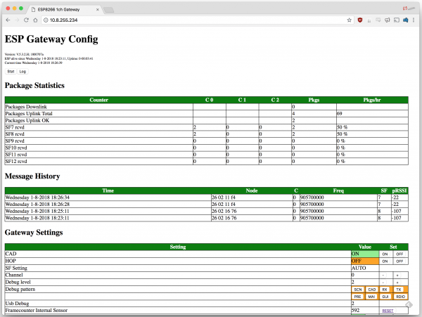
After the ESP32 has connected, look for it to print out an IP address. Open up your computer’s web browser and plug that into the address bar. You should be greeted by the ESP Gateway Config web portal:

ESP Gateway Config served by the ESP32

Config and log page served by the ESP32.

This web page can be used to monitor messages coming through and what frequencies and spread factors they came in on. It can also be used to change your gateway’s configuration on-the-fly. You can adjust the channel or spread factor, or turn CAD on/off, or even turn on simplistic frequency-hopping.

Of course, to see any messages get through you’ll need a LoRa device (or devices) set up to communicate with your gateway. Check out the next section for a quick guide on setting up a second ESP32 LoRa board as a LoRa device. Alternately if you have a different SparkFun LoRa-enabled product like the SAMD21 Pro RF follow that product’s guide to set up a LoRaWAN device.

TroubleShooting

If you copy your IP address into the web browser and get a message saying the website cannot be reached, make sure your LoRaWAN and your computer are connected to the same network.

Turning a Gateway Into a Device

If you have a pair of ESP32 gateway’s you can use one of them as a LoRaWAN device. This section will get you set up with our preferred LoRaWAN Arduino library and a simple example sketch to get started.

Get the Arduino-LMIC Library to Set Up a Device

If you have a pair of ESP32 Gateways and want to set one of them up as a LoRa device, we recommend using the Arduino-LMIC library. There seem to be many versions of the Arduino-LMIC library hanging around, we’ve had good success with the library forked by mcci-catena. If you don’t want to use GitHub you can download an archived .zip file here. It will work for this guide but it may not be completely up-to-date.

Archived Arduino-LMIC from mcci-catena (ZIP)

To install the library, download the ZIP file and use the Arduino’s “Add ZIP library” feature (Sketch > Include Library > Add .ZIP Library) to import the zip file into your Arduino sketchbook.

Configure LMIC

Before can use an example sketch in the LMIC library, you’ll need to configure it. To configure the library, navigate to the “arduino-lmic” library in your ..{Arduino Sketchbook}/libraries folder. Then go to project_config and open lmic_project_config.h.

Here you’ll define which frequency bands your LoRa device will use. You can also turn on debugging and enable/disable a host of features with definitions in this file.

Make sure you uncomment one (and only one!) of the “CFG…” declarations. If you’re in the USA, uncomment #define CFG_us915. Ultimately, this frequency should match what you set in the gateway.

Below is my config file – I’ve turned on debugging, because I’m a log junkie.

language:c
// project-specific definitions
//#define CFG_eu868 1
#define CFG_us915 1
//#define CFG_au921 1
//#define CFG_as923 1
// #define LMIC_COUNTRY_CODE LMIC_COUNTRY_CODE_JP   /* for as923-JP */
//#define CFG_in866 1
#define CFG_sx1276_radio 1

//#define LMIC_PRINTF_TO Serial
#define LMIC_DEBUG_LEVEL 2

//#define DISABLE_INVERT_IQ_ON_RX

If you try to use the “raw” example in this library, you’ll need to uncomment DISABLE_INVERT_IQ_ON_RX, otherwise keep it commented-out.

Modify the “SPI.begin” call

Just to be sure your pin definitions are correct, I recommend modifying the SPI.begin line in arduino-lmic/src/hal/hal.cpp (line 136) to:

language:c
SPI.begin(14, 12, 13, 16);

This will ensure that your SPI pins are set correctly – this may only be necessary if you’re not using the custom “SparkFun LoRa gateway 1-Channel” Arduino board.

Load the Single-Channel Device Example

We’ve taken one of the examples in the Arduino-LMIC library and modified it to work more reliably with a single-channel gateway.

Click the button below to download the example. Then open up ESP-1CH-TTN-Device-ABP.ino:

Download the single-channel LoRaWAN device example (ZIP)

Among the modifications in this example are the pin map between radio and ESP32 – set with these lines:

language:c
const lmic_pinmap lmic_pins = {
  .nss = 16,
  .rxtx = LMIC_UNUSED_PIN,
  .rst = 5,
  .dio = {26, 33, 32},
};

We’ve also modified the enabled channels to only use a single channel with the lines below (note this modification hasn’t yet been tested on non-US frequency bands).

language:c
// First disable all sub-bands
for (int b = 0; b < 8; ++b) {
  LMIC_disableSubBand(b);
}
// Then enable the channel(s) you want to use
LMIC_enableChannel(8); // 903.9 MHz

The spread factor is set near the end of setup() with the LMIC_setDrTxpow(DR_SF7, 14); line. This can be replaced with DR_SF8, DR_SF9, or DR_SF10 at the default 903.9MHz frequency.

You can’t compile successfully until you fill in these lines:

// LoRaWAN NwkSKey, network session key
// This is the default Semtech key, which is used by the early prototype TTN
// network.
static const PROGMEM u1_t NWKSKEY[16] = { PASTE_NWKSKEY_KEY_HERE };

// LoRaWAN AppSKey, application session key
// This is the default Semtech key, which is used by the early prototype TTN
// network.
static const u1_t PROGMEM APPSKEY[16] = { PASTE_APPSKEY_KEY_HERE };

// LoRaWAN end-device address (DevAddr)
static const u4_t DEVADDR = 0xPASTE_DEV_ADDR_HERE;

with something. If you want to test the gateway right now go ahead and fill the two arrays with 16 bytes each and the DEVADDR with a 4-byte wide number. If you do this and upload the code then you should see the gateway receiving messages. (If you’re having trouble make sure that the device and the gateway are configured to use the same channel and spreading factor).

If you are OK waiting then leave these blank until you get your actual keys and device address from The Things Network in the next section.

Routing Into The Things Network

The final components to a LoRaWAN network are a server and application. Although it is possible to make your own server we’ve already configured the gateway to send data to The Things Network through one of their routers like “router.eu.thethings.network”. This is an easy and free way to get started with LoRaWAN so we recommend starting this way.

Single-Channel Blues

At the trade-off of being low-cost, this gateway is only capable of monitoring a single LoRa channel on a limited set of spread factors. Single-channel gateway's don't get much support from LoRaWAN platforms like The Things Network, as they are not, necessarily, LoRaWAN-compliant. They are, however, a great way to begin exploring the world of LoRa and LoRaWAN!

If you haven’t already, head to thethingsnetwork.org and create an account. Once that’s done, go to your Console.

The Things Network Console

Create an Application

If your data is being sent to The Things Network’s servers then you can create an application to access that data. This works by registering devices with unique cryptographic keys so that your data is only visible to you.

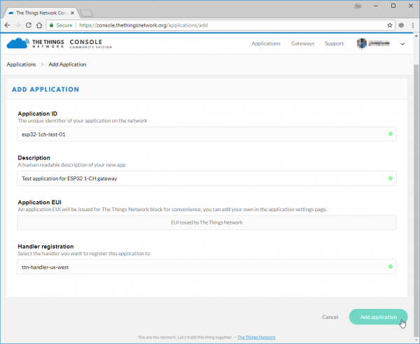
In order to register a device, you first need to create an application to house it under. In the console, click “Applications” then click “add application”.

Fill out any ID and description you’d like. The Application EUI will automatically be generated when you create the application. You can also pick your preferred handler for the application (e.g. ttn-handler-us-west).

Creating a TTN application

Hard time seeing? Click on the image for a closer look!

Create and Configure a Device

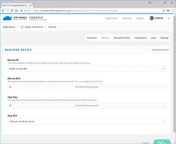
Next register a device in your application. Under the “Devices” section, click “register device”.

This is again pretty simple. Fill out a unique device ID, click the “generate” button under “Device EUI” to automatically generate a EUI. Then click “Register.”

Creating a TTN device

Hard time seeing? Click on the image for a closer look!

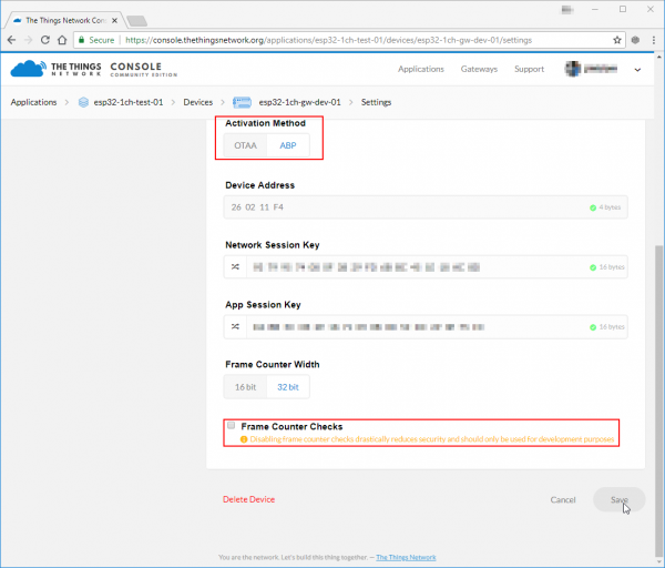
This example sketch only supports ABP activation, so you’ll need to modify that in the device settings. In the “Device Overview” page, click “Settings”. From there, under “Activation Method” click ABP. I also recommend disabling Frame Counter Checks. The gateway is capable of frame-counter checks, but it can get out of sync – especially if you have another gateway nearby.

Modifying TTN device settings

Hard time seeing? Click on the image for a closer look!

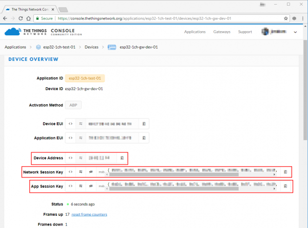
Save the settings and go back to your “Device Overview” page. You should see new keys, including “Network Session Key”, “App Session Key”, and “Device Address.” These will need to be plugged into the device sketch and uploaded to the device - which we will cover in the next section.

Update the Example Code

With your application, network session, and device keys in-hand, you’re ready to finish configuring the ESP32 LoRa device sketch and start posting data!

On the “Device Overview” page, click the “code” symbol (<>) next to “Network Session Key” and “App Session Key” – this will make the key visible and display it as a 16-byte array. Copy each of those keys, and paste them in place of the {PASTE KEY HERE} place-holders. “Network Session Key” should be pasted into the NWKSKEY variable and “App Session Key” should be pasted into the APPSKEY variable.

The DEVADDR variable expects a single 32-bit variable, so copy the “Device Address” key as shown and paste that into the PASTE_DEV_ADDR_HERE placeholder.

Grabbing your device keys

Hard time seeing? Click on the image for a closer look!

Here’s an example of what your three constants should look like once done:

language:c
// LoRaWAN NwkSKey, network session key
// This is the default Semtech key, which is used by the early prototype TTN
// network.
static const PROGMEM u1_t NWKSKEY[16] = { 0x01, 0x23, 0x45, 0x67, 0x89, 0xAB, 0xBD, 0xEF, 0x01, 0x23, 0x45, 0x67, 0x89, 0xAB, 0xCD, 0xEF };

// LoRaWAN AppSKey, application session key
// This is the default Semtech key, which is used by the early prototype TTN
// network.
static const u1_t PROGMEM APPSKEY[16] = { 0xFE, 0xDC, 0xBA, 0x98, 0x76, 0x54, 0x32, 0x10, 0xEE, 0xDC, 0xAA, 0x98, 0x76, 0x54, 0x32, 0x10 };

// LoRaWAN end-device address (DevAddr)
static const u4_t DEVADDR = 0x01234567;

And that’s it! Now upload the code to your LoRa Gateway 1-Channel board (the one that is supposed to be the device, that is!)

Testing the Code

After setup, the device should immediately send a “Hello, World” message. It’ll continue to send a message every minute or any time the “0” button on the board is pressed.

To check if your gateway is receiving the message, you can either check the Serial Monitor or monitor the ESP Gateway Config page served by the gateway. Every time a message is received it should be added to the “Message History” table.

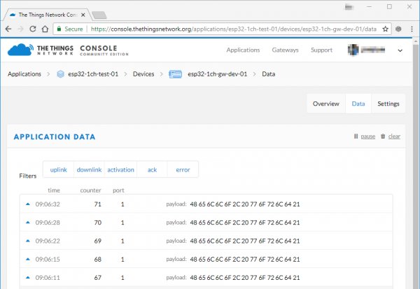
If messages are getting through to your gateway, click the “Data” tab on your device to check for new messages.

TTN device data visible

Hard time seeing? Click on the image for a closer look!

The message’s payload – which was encrypted between leaving the device and getting into your application – should be a series of hex values corresponding to “Hello, world”.

Decoding the Message

You may have noticed in the Application Data window that your payload is shown in raw bytes. In order to see “Hello, World!” encoded in ASCII, the way you sent it, you’ll need to decode the payload. The Things Network includes tools for doing this right in the console! Navigate to the Application Overview page for your application and click on the Payload Formats tab. This menu allows you to write functions which will be applied to all incoming packets for this application.

Screenshot of the Payload Formats page, showing a field labeled "decoder" where code can be typed. Some example code is in the field by default. It doesn't appear to return anything.

Hard time seeing? Click on the image for a closer look!

So let’s write our own decoder. We need to take the raw byte data and return a string that contains all of the characters corresponding to each byte. Take a look at this solution and then we’ll walk through it:

language:js
function Decoder(bytes, port) {

    return {
        ASCII: String.fromCharCode.apply(null, bytes)
    };

}

Decoder is a Javascript function that The Things Network has already set up for us. It takes two arguments called bytes, an array containing our payload, and port, the LoRaWAN™ “FPort” of the packet. FPort identifies the end application or service that the packet is intended for. Port 0 is reserved for MAC messages. We don’t need to know anything about the port number for our example.

We can return any value that we want from the Decoder function and it will appear alongside our payload in the Application Data window. In the example above, I’ve created a new property called “ASCII” which is equal to String.fromCharCode.apply(null, bytes). To break this down a little more, we’re returning a new String object called “ASCII,” and we’re using the Javascript apply() method to call fromCharCode() with the argument bytes and stuff the result into our new String. The fromCharCode() method simply steps through each byte in the array bytes (which, remember, contains our payload) and returns the ASCII character represented by that character code.

After copying the above code into your decoder function, scroll down and click the save payload functions button. Now return to the Application Data window and you should see that all packets received after the decoder function was changed now have a new property:

Another screenshot of the Application Data page, this time showing several packets received. The latest packet at the top of the list has a new field beside payload labeled "ASCII" with the value "Hello, world!"

Hard time seeing? Click on the image for a closer look!

Our packet has been decoded! Excellent!

Troubleshooting

If messages are not getting to your gateway, first make sure the channel and spread factor match up. Left unchanged, the device example code should be sending data out on the 903.9MHz channel at a spread factor of 7 (That’s assuming you’ve set the LMIC library to CFG_us915. If it’s set to a European frequency spectrum, it’ll be 868.1MHz, SF7).

You can use the gateway’s web server to adjust these setting on the fly. Note that the channel numbers should sequentially match the freqs array in loraModem.h– e.g. channel 0 should be 903.9MHz (again, assuming US frequencies).

If messages are getting to your gateway, but not showing up on your TTN device console, consider changing the _TTNSERVER variable in “ESP-sc-gway.h”. I haven’t had success with the us-west router, but "router.eu.thethings.network" has worked perfectly (even in the US).

Resources and Going Further

Thanks for coming on this single-channel LoRaWAN gateway journey with us! Here are a few links and documents that might prove handy as you continue exploring the world of LoRa with this board:

Need Inspiration? Check out some of these fun IoT tutorials from SparkFun:

Simblee LilyPad Hookup Guide

The Simblee LilyPad lets you easily integrate Bluetooth Low Energy and mobile apps into your e-textiles projects.

IoT Industrial Scale

What does a baby elephant weigh? How much impact force does a jump have? Answer these questions and more by building your very own IoT industrial scale using the SparkFun OpenScale.

IoT Weight Logging Scale

This tutorial will show you how to make a scale that logs your weight to a custom website on the Internet. The principles can be extrapolated to any type of data.

SparkFun SAMD21 Pro RF Hookup Guide

Using the super blazing, nay blinding, fast SAMD21 whipping clock cycles at 48MHz and the RFM96 module to connect to the Things Network (and other Radio woodles).

learn.sparkfun.com | CC BY-SA 3.0 | SparkFun Electronics | Niwot, Colorado

LTE Cat M1/NB-IoT Shield Hookup Guide

$
0
0

LTE Cat M1/NB-IoT Shield Hookup Guide a learn.sparkfun.com tutorial

Available online at: http://sfe.io/t816

Introduction

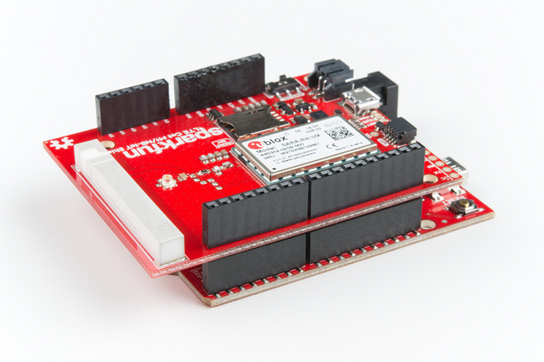
The SparkFun LTE Cat M1/NB-IoT Shield equips your Arduino or Arduino-compatible microcontroller with access to data networks across the globe. It adds wireless, high-bandwidth cellular functionality to your IoT project while maintaining low power consumption and a small footprint.

SparkFun LTE CAT M1/NB-IoT Shield - SARA-R4

SparkFun LTE CAT M1/NB-IoT Shield - SARA-R4

CEL-14997
$79.95

You can either purchase the SparkFun LTE Cat M1/NB-IoT Shield individually, as in the link above, or packaged with a Hologram SIM card. The Hologram SIM card provides global connectivity on an extremely reasonable pricing model. They also provide software tools like cloud data and SMS messaging and webhooks for routing data from your cell shield to popular web services.

SparkFun LTE CAT M1/NB-IoT Shield - SARA-R4 (with Hologram SIM Card)

SparkFun LTE CAT M1/NB-IoT Shield - SARA-R4 (with Hologram SIM Card)

CEL-15087
$84.95

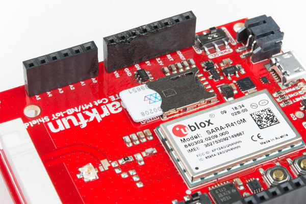
At the heart of the LTE Cat M1/NB-IoT shield is a u-blox SARA-R410M-02B LTE Cat M1/NB-IoT modem. Cat M1 (Category M1) and NB-IoT (Narrowband IoT) are both Low Power Wide Area Network (LPWAN) technologies that are designed to provide cellular communication to small IoT devices. They operate on LTE network bands just like most smartphones, and should be supported by most cellular network carriers.

The u-blox module commmunicates over a UART via a simple AT command set. We’ve provided a library to help you get started with everything from sending SMS text messages to communicating with servers over a TCP/IP connection.

Both the module and library support an I2C GPS interface, so you can plug in a u-blox GPS module and start remotely tracking your project.

Required Materials

In addition to the shield itself, we recommend the following items to follow along with this tutorial. You may not need everything though depending on what you have. Add it to your cart, read through the guide, and adjust the cart as necessary.

Arduino or Arduino-Compatible Development Board– The LTE Cat M1/NB-IoT Shield is primarily designed to work as a…shield. It should be compatible with most Arduino-type development boards, including the Arduino Uno, SparkFun RedBoard, SparkFun BlackBoard, and SAMD21 Dev Breakout.

SparkFun RedBoard - Programmed with Arduino

SparkFun RedBoard - Programmed with Arduino

DEV-13975
$19.95
38
Arduino Uno - R3 SMD

Arduino Uno - R3 SMD

DEV-11224
$29.95
22
SparkFun SAMD21 Dev Breakout

SparkFun SAMD21 Dev Breakout

DEV-13672
$25.95
6
SparkFun BlackBoard

SparkFun BlackBoard

SPX-14669
$14.95
3

The shield can also be used as a breakout board for the u-blox SARA-R4 module, in which case nearly any microcontroller development board with a free UART should work. You can even use the shield’s USB interface with a Raspberry Pi, Raspberry Pi Zero or, really, any Windows/Mac/Linux device with a free USB port.

Headers– To connect the shield to your Arduino you’ll need to solder headers into it. We recommend the stackable R3 headers, but male headers can also do the trick.

Female Headers

Female Headers

PRT-00115
$1.50
7
Arduino Stackable Header Kit - R3

Arduino Stackable Header Kit - R3

PRT-11417
$1.50
12

Soldering Tools– You’ll also need soldering tools to connect the headers to your shield. A basic soldering iron and solder should be enough.

Soldering Iron - 60W (Adjustable Temperature)

Soldering Iron - 60W (Adjustable Temperature)

TOL-14456
$12.95
6
Solder Lead Free - 15-gram Tube

Solder Lead Free - 15-gram Tube

TOL-09163
$3.50
2

SIM card– A nano SIM card will be required to provide connectivity for the LTE CAT-M1 Shield’s u-blox module. If you’ve purchased the Hologram/SparkFun LTE Shield Combo, then you’re all set. Otherwise, there are a variety of connectivity suppliers including AT&T, T-Mobile, and Verizon.

Optional Materials

In addition to those required items, these bits and pieces can help add functionality to your LTE Shield, so you can take it even further:

LiPo Battery– The LTE Shield includes a LiPo battery charger. This LiPo can be used to power both your Arduino and the shield simultaneously. Any of the below batteries should work with the shield:

Lithium Ion Battery - 1Ah

Lithium Ion Battery - 1Ah

PRT-13813
$9.95
7
Lithium Ion Battery - 2Ah

Lithium Ion Battery - 2Ah

PRT-13855
$12.95
3
Lithium Ion Battery - 850mAh

Lithium Ion Battery - 850mAh

PRT-13854
$9.95
2
Lithium Ion Battery - 6Ah

Lithium Ion Battery - 6Ah

PRT-13856
$29.95
5

Micro-B USB cable– The shield’s SARA-R4 module supports a USB interface, which can be used for both power and a communication interface. A micro-B USB cable isn’t required, but may be helpful if you want to power your project via USB or give the SARA-R4 module’s USB interface a spin.

USB micro-B Cable - 6 Foot

USB micro-B Cable - 6 Foot

CAB-10215
$4.95
11
USB Micro-B Cable - 6"

USB Micro-B Cable - 6"

CAB-13244
$1.95
3
SparkFun Rugged microB Cable - 1m

SparkFun Rugged microB Cable - 1m

CAB-14742
$3.95
SparkFun Traveler microB Cable - 1m

SparkFun Traveler microB Cable - 1m

CAB-14741
$3.95

Suggested Viewing

Suggested Reading

This tutorial builds on a variety of electronics, programming, and engineering concepts. If any of the subjects of these tutorials sound foreign to you, consider checking them out before continuing on:

Serial Communication

Asynchronous serial communication concepts: packets, signal levels, baud rates, UARTs and more!

Installing an Arduino Library

How do I install a custom Arduino library? It's easy! This tutorial will go over how to install an Arduino library using the Arduino Library Manager. For libraries not linked with the Arduino IDE, we will also go over manually installing an Arduino library.

Arduino Shields

All things Arduino Shields. What they are and how to assemble them.

Logic Levels

Learn the difference between 3.3V and 5V devices and logic levels.

If you aren’t familiar with the Qwiic system, we also recommend reading here for an overview.

Qwiic Connect System

Hardware Overview

It may not look like it, but there’s a lot going on on the LTE Cat M1/NB-IoT Shield. This page covers all of the hardware features included on the board. Take a quick peruse through it to make sure you don’t get tripped up by the UART- or power-select switches, the power/reset buttons, or the external USB and GPS interfaces.

Power Supply

The u-blox SARA-R410M-02B module uses a relatively low amount of power. Peak current consumption is about 200mA (a far cry from past cellular shields which occasionally pulled upwards of 2A) at a voltage supply of 3.3V. Logic on the module is all 1.8V, but never fear – we’ve included logic-level shifting included on-board (see the Logic-Level Selection section for more information).

Power supply highlighted -- switch, LiPo, USB, and Arduino power header

The shield is designed to take power from one of three sources:

  1. Arduino– The shield receives power from the Arduino’s 5V supply pin.
  2. LiPo Battery– A 3.7-4.2V LiPo battery can be connected to the black 2-pin JST connector.
  3. On-board micro-B USB connector– A micro-B USB cable can be connected from your computer or a USB wall wart to supply power to the shield. This may be useful if you’re using the shield as more of a “breakout board.” (This connector can also be used to provide a USB interface to the u-blox module – see the USB Interface section below).

The PWR_SEL switch should be used to select the power source. In the Arduino position, the shield will receive power from the Arduino. In the SHIELD position, the shield will supply power to the Arduino.

LiPo Charging

The shield includes an MCP73831 LiPo charger, which is configured to power a single-cell LiPo battery at up to 500mA.

The battery can be charged by either connecting a micro-B USB cable to the shield, or by connecting the shield to a powered Arduino and setting the PWR_SEL switch to ARDUINO.

Power and Reset Buttons

The LTE Cat M1/NB-IoT Shield includes a pair of SPST buttons labeled RESET and POWER. These are connected directly to the SARA-R4 module’s PWR_ON and RESET_N pins.

Hardware power and reset buttons, and Arduino pins highlighted

By default the SARA-R4 module is turned off, to turn it on – as you might any other cell phone – you need to hold the POWER button down for about 3 seconds.

The RESET button resets the SARA-R4 module to its default configuration. In most cases you should not need to use this button. If you do, hold it down for at least 10 seconds while the module is on. Note that this button has no affect on the Arduino – it won’t reset your sketch.

Both of these pins are also wired to the Arduino:

Pin FunctionButton LabelArduino PinDescription
Power OnPOWER5Power the SARA-R4 module on or off. Hold for ~3 seconds.
ResetRESET6Reset the SARA-R4 module configuration to default. Hold for >10 seconds

The library is designed to toggle the POWER pin if the shield is not communicating, so you may be able to avoid pressing this button at all.

UART Interface

All communication between your Arduino and the SARA-R4 module will occur via an AT command interface over a simple UART – RX and TX pins.

hardware/software serial interfaces, select switch, and debug port

Designed with a simple Arduino Uno in mind, this shield can either communicate with the SARA-R4 module via either a hardware or software serial interface. The SERIAL switch can either be set to HARD for hardware serial on pins 0/1 or SOFT for software serial on pins 8/9.

Arduino Receive (Cell Transmit)Arduino Transmit (Cell Receive)
Software Serial89
Hardware Serial01

FTDI Header

The UART signals are also broken out to a 6-pin “FTDI” serial header. If you’re not using the shield as a shield – more-so as a breakout – this header may be useful. You can connect any 3.3V or 5V USB-to-Serial converter (like the Serial Basic) to this header, and directly communicate with the SARA-R4’s UART.

This header is not affected by the SERIAL-select switch. External power must be supplied to the LTE shield – either via USB or LiPo battery.

LED Indicators

A trio of LEDs are broken out between the USB and GPS connectors. The table below documents each of these LEDs color and indication:

LED LabelLED ColorLED indication
PWRRedPower supplied to SARA-R4 module
CHGYellowLiPo battery charging (may illuminate if no battery is connected)
NETBlueCellular network status. Illuminates when the SARA-R4 module is connected to a cellular network. (Must be configured in software.)

The most important of these LEDs is the blue “NET” indicator. This LED will illuminate when your SARA-R4 module is properly configured, is connected to a SIM card, and is communicating with a cell network. By default, the pin SARA-R4 connected to this LED is not configured, but the library should take care of that upon initialization.

Logic-Level Selection

The SARA-R4 module’s GPIO pins all operate at 1.8V logic levels. Fortunately, the shield includes level shifting which should convert either 3.3V or 5V signals to 1.8V.

On most Arduino, selection of the high end of the logic-level translation should be automatic. Voltage supplied from the Arduino’s IOREF pin should set it. If so, ignore what comes next.

IOREF jumper

If your Arduino does not have an IOREF pin, or does not supply a valid logic level on that pin, you should use the IOREF jumper to select your Arduino’s logic level.

GPS Port

If you want to easily add location-tracking to your project, the LTE Shield’s Qwiic GPS port can connect to a handful of u-blox GPS modules. We’re adding more compatible modules soon. For now, the supported modules are:

SparkFun GPS-RTK Board - NEO-M8P-2 (Qwiic)

SparkFun GPS-RTK Board - NEO-M8P-2 (Qwiic)

GPS-15005
$199.95
1

The LTE Shield Arduino library includes support for reading this GPS module via the SARA-R4’s AT command set.

Note that this Qwiic connector is only designed to support u-blox-based GPS modules. It does not support any other GPS modules or sensors.

LTE Antenna

The LTE Shield includes a ceramic, SMD antenna – a Molex 1462000001. The antenna has a gain of 3.8dBi around 1.7GHz to 2.7GHz.

If your project requires an external antenna, the onboard antenna can be disconnected and the included U.FL antenna can be used. To disconnect the onboard ceramic antenna, grab a hobby knife and slice across the big metal pad near the U.FL connector – between the two, white, silkscreen dots as highlighted in the image below along a black line.

Internal Antenna Jumper Highlighted to Indicate Where to Cut

Once the jumpers have been adjusted and an external antenna has been connected, your setup should look like the image below.

Antenna jumper cut with u.fl antenna attached

Once you’ve cut the jumper, its safe to add your own antenna via a U.FL connector.

USB Interface

The SARA-R4 features a USB interface which, with the proper drivers installed, can provide your Raspberry Pi or, really, any other machine with a USB interface to Cat M1/NB-IoT. Using the LTE Shield’s USB interface is almost as simple as plugging in a USB cable to your computers USB port.

Unfortunately, the UART and USB interfaces can not be used concurrently. To use the USB interface, close the VUSB_DET jumper on the back side of the board.

VUSB_DET Jumper

Hardware Hookup

To assemble the LTE Shield, you’ll need basic soldering tools and skills. New to soldering? No worries! Check out our through-hole soldering tutorial.

How to Solder: Through-Hole Soldering

September 19, 2013

This tutorial covers everything you need to know about through-hole soldering.

Solder on Headers

To connect the SparkFun LTE Shield to your Arduino, you’ll need to solder headers into the through-hole Arduino pins. We recommend either Stackable headers– if you want to stack more shields on top – or male headers.

Soldering into the two 8-pin, one 6-pin, and one 10-pin header should be enough to get your shield snugly fitting and electrically connected.

hardware hookup -- stackable headers installed

Plug in a SIM Card

You’ll also need to slide an activated SIM card into your shield. As you insert the SIM card, it’s “notch” should match the pattern on the board’s silkscreen as well as that on the SIM card holder itself.

Inserting a SIM card

Don’t forget to activate your SIM if that’s required by your network provider!

Activate Your Hologram SIM

If you're using a SIM card from Hologram, you'll need to follow a few quick steps to activate your SIM card.

  1. Log in to your Hologram account, or create one
  2. Click the blue + Activate SIM button in the upper-right-corner of your Dashboard.

  3. Activate hologram SIM


  4. Select your plan – in most cases “Maker Flexible” is the way to go, but you can upgrade.
  5. Enter your SIM card’s CCID. This number can be found printed on both your nano-SIM card and in the larger digits below the bar code. Then select continue.
  6. Next you can decide whether to enable auto-refill or not and continue. Finally, you’ll be greeted with a summary page – hit “Activate” and you’re ready to go!

For more help activating your Hologram SIM card, check out their Connect Your Device documentation.

Supply Power

Once you’ve soldered on the headers, and plugged in at least a SIM card. It’s time to supply power and start LTE'ing!

The shield can be powered via either an Arduino or the on-board USB or LiPo battery connectors. For the purposes of this tutorial, we’d recommend powering via Arduino.

Set the PWR_SEL switch to ARDUINO. Plug the shield into your Arduino, then plug your Arduino into your computer via USB.

Powering shield and Arduino via Arduino

Once plugged in, you should see the shield’s red PWR LED illuminate (you may also see the yellow CHG LED turn on as well – even without a battery plugged in – no worries.) The blue NET LED will probably not turn on yet. For that, we need to configure the shield. And for that, we need the SparkFun LTE Shield Arduino Library. Read on!

LTE Shield Arduino Library

Note: This example assumes you are using the latest version of the Arduino IDE on your desktop. If this is your first time using Arduino, please review our tutorial on installing the Arduino IDE. If you have not previously installed an Arduino library, please check out our installation guide.

The SparkFun LTE Shield Arduino library is designed to simply interface your Arduino to the Cat M1/NB-IoT Shield. The shield handles everything from initialization (turning on the SARA-R4 module, configuring your network, setting GPIO modes) to sending/receiving SMS and communicating over a TCP network interface.

To manually download the library, navigate to GitHub repository and download the repository as a ZIP folder (or click the link below):

Download the SparkFun LTE Shield Arduino Library (ZIP)

To manually install the library via a ZIP folder, open Arduino, navigate to Sketch>Include Library>Add .ZIP Library, and select the ZIP folder you just downloaded.

Example 0: Network Registration

The first example in this tutorial is the most critical. Here we demonstrate how to configure your LTE Shield’s SARA-R4 module to communicate with your network of choice. This is a configuration that usually only needs to happen once. After you’ve successfully run this sketch, your Arduino should be all set up for SMS and TCP/IP messaging.

To begin, load up this example by going to File>Examples>SparkFun_LTE_Shield_Arduino_Library>00_Register_Operator.

Opening example 0

Before uploading the sketch, you may need to adjust the value of MOBILE_NETWORK_OPERATOR and APN. The first variable, sent as a parameter to lte.setNetwork, defines the mobile network operator your LTE shield should configure itself to communicate with. It should be one of the below values:

language:c
// Network operator can be set to either:
// MNO_SW_DEFAULT -- DEFAULT
// MNO_ATT -- AT&T 
// MNO_VERIZON -- Verizon
// MNO_TELSTRA -- Telstra
// MNO_TMO -- T-Mobile
const mobile_network_operator_t MOBILE_NETWORK_OPERATOR = MNO_SW_DEFAULT;
const String MOBILE_NETWORK_STRINGS[] = {"Default", "SIM_ICCD", "AT&T", "VERIZON", 
  "TELSTRA", "T-Mobile", "CT"};

Your access point name (APN), is provided by your SIM card provider. If you’re using a Hologram SIM, this should be a string'ed "hologram". This value is provided to the lte.setAPN() function.

language:c
// APN -- Access Point Name. Gateway between GPRS MNO
// and another computer network. E.g. \"hologram\"
const String APN = "hologram";

After uploading the sketch, open up your serial monitor to check the status of your shield’s registration. This example is interactive. After possible network operators are scanned, you’ll need to enter one of a handful of options to attempt connecting to that operator.

Registration example in terminal

You’ll need to be a little patient after uploading this sketch. Depending on the state of your shield, it can take about 30 seconds for the sketch to initialize your shield. It can also take up to three minutes for the shield to scan for network operators in its area.

Some times your choice of network operator will be limited to a set of numerical-only options – a combination of mobile country codes (MMC) and mobile network codes (MNC). For example, AT&T in the example above is an MCC/MNC combination of 310 and 410, respectively – that’s the operator we select. (“313 100” is an AT&T First Responders Network and “310 260” is T-Mobile.)

If you need to do some digging (or just trial-by-error) to discover which MMC/MNC is which, check out the searchable, comprehensive list at mcc-mnc.com and/or The Roaming Zone.

What's Going On at Start-Up

The LTE Shield can take a handful of seconds to start up if you've just plugged it in and haven't triggered the power button.

As it initializes communication with the shield, the Arduino library must attempt to verify that the shield is on while also tuning the baud rate down from a potentially unknown baud rate (though, most likely, 115200 bps) to 9600 bps.

On start-up, the library will cycle through the SARA-R4's supported baud rates, and attempt to establish communication. This process may take up to 5 seconds. If the shield doesn't respond, the library will assume it's powered off. It will cycle the POWER button, then start the "autobaud" process over again.

In all, this process can take up to 30 seconds. You should end up with a SARA-R4 module configured at 9600 baud, and ready to begin LTE'ing.

Note: You can shorten this initial power-on time by manually turning on the SARA-R4's power (hold the POWER button down for ~3 seconds).

Initializing the LTE Shield Library

There are a few declarations and function calls you’ll need in every LTE Shield library sketch.

Global Definitions

There’s, of course, the library include statement:

language:c
#include <SparkFun_LTE_Shield_Arduino_Library.h>

If you’re using a software serial port – as the examples demonstrate – you’ll also need to define a SoftwareSerial object with RX on pin 8 and TX on pin 9:

language:c
// We need to pass a Serial or SoftwareSerial object to the LTE Shield 
// library. Below creates a SoftwareSerial object on the standard LTE
// Shield RX/TX pins:
SoftwareSerial lteSerial(8, 9);

And, finally, you’ll need to declare an LTE_Shield object, which we’ll use throughout the sketch for SMS-sending, and TCP/IP interactions. This object optionally takes two parameters – the POWER and RESET Arduino pins. By default these parameters should match the shield defaults, so they are not usually required.

language:c
// Create a LTE_Shield object to be used throughout the sketch:
#define POWER_PIN 5
#define RESET_PIN 6
LTE_Shield lte(POWER_PIN, RESET_PIN);

Setup Requirements

With your global variables declared, initializing the shield library is as simple as calling lte.begin(SerialPort). SerialPort should either be the SoftwareSerial port you declared in globals, or a hardware serial port if that’s supported by your Arduino board.

begin() will return true on a successful initialization of the shield or false if communication with the SARA-R4 module fails.

The examples in this library all assume a software serial port on pins 8 and 9. So the begin statement below should work.

language:c
if ( lte.begin(lteSerial) ) {
  Serial.println("Successfully initialized the LTE shield via software serial!");
}

If, on the other hand, you’re using a hardware serial port (on pins 0/1) to communicate with the shield, the begin statement below may be used:

language:c
if ( lte.begin(Serial1) ) {
    Serial.println("Initialied SARA-R4 module on a hardware serial port.");
}

The library will take care of all the begin(), write(), and read() functions provided by your serial port.

Example 1: Send an SMS

Our next example in the LTE Shield Arduino library demonstrates how to send an SMS. Note that this example does require your SIM card’s plan supports outbound SMS text messages – they may incur a fee, so be mindful of how often you run the sketch.

To load this sketch, navigate to File>Examples>SparkFun LTE Shield Arduino Library>01_SMS_Send.

Before uploading the code, modify the value of DESTINATION_NUMBER to that of your desired text message destination.

language:c
// Set the cell phone number to be texted
String DESTINATION_NUMBER = "11234567890";

Note that the SMS destination number should include the country code (e.g. “1” for US). For example, to text SparkFun (if SparkFun’s corporate phones could receive SMS messages) at 303-284-0979, you’d set the DESTINATION_NUMBER string to "13032840979".

Once your destination phone number is set, upload the code and open your serial monitor (9600 baud). In the serial monitor, set the line-ending dropdown to “Newline.”.

Sending a text message via the LTE Shield library

Then type a message and send it. After a few seconds you should see a text message appear on your destination phone.

Using the Arduino Library’s SMS-Send Functionality

The sendSMS function should be pretty straightforward to use. The function takes two parameters: a String'ed phone number and a String'ed message to send.

language:c
LTE_Shield_error_t LTE_Shield::sendSMS(String number, String message);

Consider building a String variable before sending it to the sendSMS function. You can add variables – including digitalRead()’s and analogRead()’s to the String by using the String() operator. The powerful String object includes easy concatenation with the += operator (or concat()). For example:

language:c
String messageToSend;
int time = millis();
messageToSend = "A0 = " + String(analogRead(A0)); // Add A0 to 
messageToSend += "\r\n"; // Create a new line
messageToSend += "Time = " + String(time);
lte.sendSMS(DESTINATION_NUMBER, messageToSend);

The sendSMS function does return an error/success response. Check for a return value of LTE_SHIELD_SUCCESS (set to 0) on success, or a value greater than 0 on an error.

Example 2: Send a Hologram Message

Our next example demonstrates how to send a message to the Internet via the SARA-R4’s support for TCP/IP protocols.

This example requires a Hologram SIM card and account. If you don't have a Hologram SIM, check out the last section of this example for tips on using the shield's TCP socket capabilities.

Load this example by opening File>Examples>SparkFun LTE Shield Arduino Library>02_TCP_Send_Hologram.

Before uploading this example, you’ll need your Hologram device’s device key. This can be found in your Hologram dashboard. Navigate to your device, and click the “DEVICE KEY +” in the top-left-ish corner.

Finding the Hologram device key

With that set, upload away! Then open the serial monitor at 9600 baud. As with the previous example, set your line-ending setting to Newline.

Open up your Hologram dashboard, then, from the serial monitor, type a message you’d like to send to the Hologram messaging server.

Message from serial port to Hologram

After a few seconds, you should see the message appear in your device’s Hologram dashboard.

Hologram message receive

Using TCP/IP Sockets

This example demonstrates how to use the LTE Shield’s TCP/IP socket capabilities. Sockets are a very common interprocess communication tool for sending and/or receiving data across a variety of networking protocols. In this case, we’ll be using socket to send data over a TCP network link. The SARA-R4 module supports up to seven concurrently-open sockets – usually we’ll only need one-or-two at a time.

To begin, open a socket with the socketOpen function. This function takes one parameter – an indication of whether you want to open a TCP or UDP socket. Possible parameters are LTE_SHIELD_TCP or LTE_SHIELD_UDP.

language:c
int socket;
socket = lte.socketOpen(LTE_SHIELD_TCP);
if (socket < 0) {
  Serial.println("Unable to open a socket");
}

socketOpen should return a value between 0 and 6. This is your socket – protect it well!

Once your socket is open, it’s time to use it to connect to a server. For that, there’s the socketConnect function. This function takes a socket number, URL or IP address, and port to connect to. In this example we use the socket received from socketOpen and use it to connect to hologram.io on port 9999.

language:c
const char HOLOGRAM_URL [] = "cloudsocket.hologram.io";
const unsigned int HOLOGRAM_PORT = 9999;
if (lte.socketConnect(socket, HOLOGRAM_URL, HOLOGRAM_PORT) == LTE_SHIELD_SUCCESS) {
  // Send our message to the server:
  Serial.println("Connected to Hologram server!"));
}

Once you’re connected to the server, it’s time to send some data! For that, there’s the socketWrite function. This function takes, again, a socket, and a String'ed message. You’ll need to be careful with the message if you’re sending it to the Hologram servers. It should be a JSON-encoded String of the format described here: https://hologram.io/docs/reference/cloud/embedded/#send-a-message-to-the-hologram-cloud. (See the example code for help constructing a compatible JSON string.)

language:c
String message = "{\"k\": \"a8F8asd4\", \"d\":\"Hello, world!\"}"
if (lte.socketWrite(socket, message) == LTE_SHIELD_SUCCESS) {
  Serial.println("Successfully sent message!");
}

Finally, you can close a socket using the socketClose function. Sometimes a server will close the socket on its side, but it helps to sometimes be pre-emptive in your socket-closing.

language:c
if (lte.socketClose(socket) == LTE_SHIELD_SUCCES) {
  Serial.println("Sucessfully closed a socket!");
}

Example 3: Receive a Hologram Message

Now that you’ve sent a message via TCP/IP services, this example demonstrates how to create a local listening socket on your LTE Shield to receive data.

Again, this example uses Hologram to send a message from a web portal down to the shield. If you don’t have a Hologram SIM, consider checking out the library-how-to at the end.

To load up the TCP receive example go to File>Examples>SparkFun LTE Shield Arduino Library>03_TCP_Receive_Hologram.

You shouldn’t need to modify anything in this example. Just upload away! After uploading open up your serial monitor. Then open up your Hologram dashboard.

Next, from your device’s Hologram dashboard type a message to send *via Cloud Data and send that data message (keep the Port as 4010 and protocol as TCP).

Hologram send data

After not too-long, you should see the message pop up in your Serial Monitor.

Serial monitor receive data from Hologram

Listening, Callbacks, and Polling

This example builds on using sockets from the last example, and introduces a couple new concepts as well.

socketListen can be used after opening a socket to set up a listening port on the SARA-R4 module. This function takes a socket to use and a port to listen on – 4010 in this example.

language:c
if (lte.socketListen(socket, 4010) == LTE_SHIELD_SUCCESS) {
  Serial.println("Listening on socket 4010");
}

While a socket is open and listening, data comes into the SARA-R4 module asynchronously. To catch this data, the library implements a poll function, which should be called as often as possible in the loop(). poll() is designed to monitor the UART, and, if it sees data come in from a socket, relay that back to the Arduino sketch.

To pull in data from the poll() function, a callback is used. This callback should provide two parameters: an int socket and a String message. The example below demonstrates how to declare a socket-read callback, register it, and poll for data:

language:c

void processSocketRead(int socket, String message) {
  Serial.println("Read: " + message);
  Serial.println("From: " + String(lte.lastRemoteIP()));
  Serial.println("Socket: " + String(socket));
}

void setup() {
  // Provide setSocketReadCallback a pointer to our socket-read callback
  lte.setSocketReadCallback(&processSocketRead);
}

void loop() {
  // Poll as much as possible to catch asynchronous data coming into LTE Shield
  lte.poll();
}

This example also demonstrates a similar callback functionality to take action on an asynchronously-closed socket. setSocketCloseCallback() can be used to set a closed-socket callback. The callback should take a single parameter – the socket closed. The example uses this callback to re-open a listening socket if that’s what the closed socket was.

Resource & Going Further

We hope this tutorial was informative and helps get you started with building an awesome, remote, connected project!

If you need any more information on the LTE Cat M1/NB-IoT Shield or the Arduino library, here are some resources to consider:

If you are using the Hologram SIM card, check out the resources below

  • Hologram - Global IoT platform provider for SIM cards
    • Documentation hub– Wealth of guides, FAQ’s, and tutorials documenting all of Hologram’s products and services.

For more tutorials, more to learn, and more project-inspiration, check out these related tutorials:

Weather Station Wirelessly Connected to Wunderground

Build your own open-source, official Wunderground weather station that connects over WiFi via an Electric Imp.

GPS Logger Shield Hookup Guide

How to assemble and hookup the SparkFun GPS Logger Shield. Never lose track of your Arduino again!

Internet of Things Experiment Guide

The SparkFun ESP8266 Thing Dev Board is a powerful development platform that lets you connect your hardware projects to the Internet. In this guide, we show you how to combine some simple components to remotely log temperature data, send yourself texts and control lights from afar.

GPS-RTK Hookup Guide

Find out where you are! Use this easy hook-up guide to get up and running with the SparkFun high precision GPS-RTK board.

learn.sparkfun.com | CC BY-SA 3.0 | SparkFun Electronics | Niwot, Colorado

3D Printed Illuminated Wand Prop

$
0
0

3D Printed Illuminated Wand Prop a learn.sparkfun.com tutorial

Available online at: http://sfe.io/t834

Introduction

In this tutorial, we will learn about how to create a theatrical prop for a performance by 3D printing a wand and adding an LED.

3D printed Illuminated Wand Prop in Low Lighting

Required Materials

To follow along with this project tutorial, you will need the following materials. You may not need everything though depending on what you have. Add it to your cart, read through the guide, and adjust the cart as necessary.

Resistor Kit - 1/4W (500 total)

Resistor Kit - 1/4W (500 total)

COM-10969
$7.95
149
Coin Cell Battery - 20mm (CR2032)

Coin Cell Battery - 20mm (CR2032)

PRT-00338
$1.95
Coin Cell Battery Holder - 20mm (Sewable)

Coin Cell Battery Holder - 20mm (Sewable)

DEV-08822
$1.25
4
Heat Shrink Kit

Heat Shrink Kit

PRT-09353
$7.95
4
LilyPad Slide Switch

LilyPad Slide Switch

DEV-09350
$1.75
1
Hook-up Wire - Black (22 AWG)

Hook-up Wire - Black (22 AWG)

PRT-08022
$2.50
1
LED - Super Bright White (25 pack)

LED - Super Bright White (25 pack)

COM-09850
$8.50
1

Tools

You will need a soldering tools, a 3D printer, and ABS filament. A heat gun or hot air rework station is optional for applying heat to heat shrink or if you want to smooth out the edges of hot glue.

TAZ 6 3D Printer

TAZ 6 3D Printer

TOL-13880
$2,499.95
2
Heaterizer XL-3000 Heat Gun

Heaterizer XL-3000 Heat Gun

TOL-10326
$13.95
16
Soldering Iron - 60W (Adjustable Temperature)

Soldering Iron - 60W (Adjustable Temperature)

TOL-14456
$12.95
6
Solder Lead Free - 15-gram Tube

Solder Lead Free - 15-gram Tube

TOL-09163
$3.50
2
Wire Strippers - 20-30AWG

Wire Strippers - 20-30AWG

TOL-14763
$14.95
1
ABS Filament 3mm - 1kg (Black)

ABS Filament 3mm - 1kg (Black)

TOL-12954
$42.95
1

You will also need:

  • Scissors
  • Hot Glue Gun and Glue Sticks
  • Sand Paper or Filer

Suggested Reading

If you aren’t familiar with the following concepts, we recommend checking out these tutorials before continuing. The flashlight kit is a good beginning kit to start with if you have not soldered before!

How to Power a Project

A tutorial to help figure out the power requirements of your project.

LilyPad Buttons and Switches

Learn about the button and switch offerings in the LilyPad line and how to use them.

Flashlight Kit

This is an assembly guide for the SparkFun Flashlight Kit, a basic learn to solder kit.

3D Print it

After browsing Thingiverse, the model that I found appealing was “jakereeves” elder wand. Head over to the thing and download the files to print the model of your size. Since the print area is small, you will need to print the part in two pieces.

Thingiverse: The Elder Wand

Understanding Your Circuit

The circuit is simple and consists of an LED, 10&ohm; resistor, LilyPad switch, and a battery holder. I chose to add a current limiting resistor between the anode (longer leg) of the LED and “+” terminal of the battery holder. The resistor was probably not necessary since a coin cell is not able to source enough current to damage the LED. Nonetheless, a resistor was still added as good practice. The LilyPad switch was added between the cathode (shorter leg) of the LED and the “” terminal of the battery holder.

LED Circuit Fritzing Diagram

While the orientation of the switch did not affect the overall functionality of the circuit, I did decided to have the ON side of the LilyPad switch facing toward the LED for the user. Also, the LilyPad coin cell holder was a bit big compared to the size of the wand so a smaller holder was chosen for the project. There will be markings on the holder to indicate the “+” and “” terminals with the alternative holder.

Dimension of LilyPad Coin Cell HolderDimension of Coin Cell Holder
Dimension of LilyPad Coin Cell Holder
[PRT-10730]
Dimension of Coin Cell Holder
[DEV-08822]

Hardware Hookup

After printing the wand on your 3D printer and removing it from the print area, you will need to remove the raft support under the wand. Carefully remove support using pliers. With my settings, there was also some support printed in the handle that needed to be removed before gluing the two pieces together. When ready, add some hot glue in the dimple of the handle and join the two pieces together.

3D Printed Wand in 2 Pieces with Raft Support

Once assembled, your wand should look similar to the image below.

3D Printed Wand Assembled

Let's start on the electronics side of the wand. The super bright white LED was bright but hard to see from all angles. To diffuse the LED and increase the viewing angle of the LED, you will need to sand the epoxy lens. Using sand paper or file, sand the outside of the LED. Make sure to hold the legs close to the LED to avoid damaging pins coming out of the epoxy lens.

Sand LED's Epoxy Lens to Diffuse the Light

Wrap a current limiting resistor around one terminal of the LED. In this case, I added a 10&ohm; resistor to the longer leg of the LED (i.e. +, anode side). Then solder and trim down the remaining terminal with a flush cutter. Make sure to be careful when handling the resistor terminals since they are thin compared to the terminals of the LED.

Current Limiting Resistor Soldered on Super Bright LED

Cut two solid core wires so that they are able to run along the length of the wand. You will want a little extra room to work with the wire. Strip the wire ends and solder one wire to the shorter leg of the LED (i.e. , cathode side). Then solder the second wire to the other end of the resistor.

Solder Wire to Terminals of LED

Cut some heat shrink to cover the exposed terminals of the LED and resistor. Slide the heat shrink down the wires and over the terminals. Wrap the wires around the wand. You will need to use one hand to hold the wires down as you twist the wires around the wand. Make sure the the wires are secure to the wand. If you are satisfied with the length of wires provided for the switch and coin cell holder's “+” terminal, apply heat to the heat shrink.

Wrap Wire Around Wand

Before soldering wires to the switch and the coin cell battery holder, take note of the location of where the components will be added. The switch will go on the top of the wand between grooves shown in the image below. The battery holder will go underneath the wand (where the raft support was removed) between the grooves as shown in the image.

alt text

You should have enough wire to add a switch and battery holder. Solder the wire that was from the LED's cathode side (i.e. “-”, longer leg) to the terminal adjacent to the ON position. If you are unsure of the polarity, test it out with a coin cell battery or multimeter.

Solder Wire to Pad Closest to LilyPad Switch's ON Side

Carefully bend the terminals of the coin cell holder using the end of a wire stripper so that it can fit nicely between the grooves of the wand.

Bend Coin Cell Holder's Terminals

Strip the other end of the wire that is connected to the resistor and slide the exposed ends of the wire through the top of the “+” terminal's through hole. If you are satisfied with the length, solder the wire to the terminal. Then cut and strip another piece of wire to add between the switch's OFF position and the holder's “” terminal.

Soldering Wires to the Battery Holder

At this point, test out the connections with a coin cell battery or multimeter. Make sure the switch is flipped to the ON position. If you are using a coin cell battery, the battery does not need to be fully inserted in the coin cell holder to light up.

Cut some clear heat shrink and slide it over the LED and wand's tip. Apply heat to the heat shrink.

Clear Heat Shrink

If you are satisfied with the connections, hot glue the bottom of the switch and coin cell battery holder to the wand. Avoid adding too much hot glue on the coin cell battery holder. If the holder's contacts to the battery are covered, it can interfere with the circuit causing the LED to not light up. Once the hot glue has cooled down, fully insert the coin cell battery into the holder.

LilyPad Switch and Coin Cell Holder Hot Glued to the Wand

The wand's handle should look similar to the image below.

Hot Glue Switch and Battery Holder

Your fully assembled 3D printed illuminated wand should look similar to the image below!

Fully Assembled Illuminated Wand

If you have not already, flip the switch to power the LED. Even in a bright room, the diffused LED was still visible!

Illuminated Wand in Bright RoomIlluminated Wand in Low Light

Repeat the steps above to make more wands as necessary for all of your wizards!

Illuminated Wands with Harry Potter Wizard Costumes and Custom Gryffindor Clip on Ties

Stress Testing in the Field

Rehearsals

How did it go when I handed the illuminated wands over to my students? Well, they did not mind the circuit being wrapped around on the outside of the wand. The kids started saying magical incantations, ran around flicking imaginary balls of energy, and tried making things levitate. As a result, NO ONE WAS FOCUSED. Luckily, I handed them their illuminated wands during their last rehearsal before the fall show. At least they were really in character?

Students in Character with Illuminated WandsIlluminated Wands Being Used in the Dark

Show Time!

When it came time for the show, everything went as planned. The illuminated wands lasted throughout tech, during the performance, and after the show. Here’s a picture of the team after they went on!

3D Printed Illuminated Wants with LED Turned On Backstage with Harry Potter Costumes and Custom Gryffindor Clip-On Ties

Making it Better

There’s always room for improvement. After the project was completed, I had a few ideas of making the prop more functional. Below are a list of possible upgrades and improvements that could be implemented for future builds.

  • Microcontroller and Sensors– If I had more time, I would have wanted to add a microcontroller and sensors (i.e. an accelerometer and gyro) to each of the wands so that the LED would only turn on based on the gestures.
  • Custom 3D Model– I would have also wanted to design a wand from scratch to include the electronics on the inside similar to the other models found on Thingiverse.

Resources and Going Further

For more information related to the project, check out the resources below:

Need some inspiration for your next project? Check out some of these related tutorials:

Prototype Wearable LED Dance Harness

A project tutorial to add an extra effect for dancers performing a choreographed piece. The harness can be added quickly under a costume.

Vox Imperium: Stormtrooper Voice Changer

Add some flair to your Imperial uniform by changing your voice using a Teensy 3.2 and Prop Shield.

TeensyView Hookup Guide

A guide to using the TeensyView OLED board to display text and graphics.

Interactive 3D Printed LED Diamond Prop

In this tutorial, we will learn about how to create an interactive theatrical prop for a performance by 3D printing a translucent diamond prop using a non-addressable RGB LED strip and AT42QT1011 capacitive touch sensing.

Or check out some of these blog posts for ideas:


learn.sparkfun.com | CC BY-SA 3.0 | SparkFun Electronics | Niwot, Colorado

nRF52840 Advanced Development With the nRF5 SDK

$
0
0

nRF52840 Advanced Development With the nRF5 SDK a learn.sparkfun.com tutorial

Available online at: http://sfe.io/t833

Introduction

Are you an nRF52840 user ready to take a leap away from the comforts of the Arduino IDE? Feeling limited by CircuitPython’s support? Maybe it’s time to set up an armgcc-based development environment of your own and dive into Nordic’s nRF5 Software Development Kit (SDK).

nRF5 SDK Icon

This tutorial will cover download and setup of every software tool – armgcc, nrfutil, and the nRF5 SDK – you need for nRF52 development. It focuses on developing for the SparkFun Pro nRF52840 Mini Breakout.

SparkFun’s nRF52840 ships with a USB-Serial DFU bootloader. So this tutorial will put extra focus on modifying the SDK to seamlessly bootload code via USB.

Pro’s and Con’s

As with any development approach, there are benefits and disadvantages to building a homebrew programming environment.

Pro’s

  • Lot’s of example applications! The list of examples in Nordic’s nRF5 SDK is exhaustive. Everything from blinky to BLE heart-rate monitors are are included in the SDK.
  • Nordic’s documentation is equally-comprehensive and well-organized. Just take a peek at the nRF5 SDK Documentation.
  • Access to more advanced features that may not have Arduino or CircuitPython support built out: NFC, ANT, capacitive-touch sensing, FreeRTOS just to name a few
  • Flexibility to use your favorite IDE/editor. Whether you’d prefer to use Eclipse, Sublime, Notepad++, or, as we’ll demonstrate in this tutorial Visual Studio Code, your options are nearly endless!

Con’s

  • We won’t lie. Setting up a from-scratch toolchain and IDE can be a daunting task. You’ll encounter errors that may seem to be impossibly isolated to your setup and your computer. If you’re stuck, feel free to reach out in this tutorial’s comments section.
  • We’re not in Arduino- or Python-land anymore. Developing with the nRF5 SDK is hard if you’ve never done it before. Whether you want to blink an LED or set up your nRF52 board as a BLE central device, there are a lot of new functions, macro’s, and programming paradigm’s to familiarize yourself with. Luckily there are a lot of examples!
  • The SDK isn' tailor-made for the SparkFun nRF52840 Mini Breakout. For most examples, you’ll need to make some Makefile (and potentially linker-script) modifications to load it onto your nRF52840 using the pre-programmed bootloader.

Bill of Materials

This tutorial is primarily designed to support the SparkFun Pro nRF52840 Mini Breakout– especially the section covering SDK modifications to enable programming-via-bootloader.

SparkFun Pro nRF52840 Mini - Bluetooth Development Board

SparkFun Pro nRF52840 Mini - Bluetooth Development Board

DEV-15025
$29.95

That said, the general setup parts of this tutorial can be made applicable to any nRF52840 – or even nRF58232 or nRF51– board. Nordic’s nRF52840 Development Kit (DK) or the nRF52840 Dongle are great boards that should work great with most of this tutorial. Beyond an nRF52840 board, you shouldn’t need anything else besides a micro-B USB cable to attach between the device and your computer.

Suggested Reading

If you haven’t read through it already, we recommend following along with our SparkFun Pro nRF52840 Mini Hookup Guide before continuing on. This tutorial will familiarize you with the hardware features of the board as well as the intricacies of the DFU/UF2 bootloader.

New!

SparkFun Pro nRF52840 Mini Hookup Guide

November 29, 2018

A hardware overview and hookup guide for the SparkFun Pro nRF52840 Mini -- a breakout for Nordic's impossibly cool Bluetooth/ARM Cortex M4 SoC.

Installing the ARM Toolchain & Nordic Tools

All of the nRF5 SDK’s examples, components, and libraries are written in C. To compile those source files you’ll need a C compiler for the ARM architecture. There are a handful of ARM C compilers out there, but we’ll be focusing on the open-source ARM GCC toolchain in this tutorial.

In addition to the compiler, you’ll need software that can take that compiled code and upload it to a Nordic nRF5 chip via either the bootloader or the SWD interface. Nordic’s nRF5x Command Line Tools include nrfjprog, which can be used to upload via the SWD debug interface. adafruit-nrfutil– a modified version of Nordic’s nrfutil is used to upload via DFU bootloader.

Compiler – ARM GNU Tools

The GNU Arm Embedded Toolchain is a collection of open-source compilers, build-, and debug-tools for ARM microcontrollers – including the ARM Cortex-M4 that make up a major chunk of the nRF52840 SoC. These tools include:

  • GNU C/C++ Compiler – A C/C++ compiler that turns your C/C++ code into machine code that the ARM can understand.
  • Binary tools – Tools that can link your compiled code together, compile assembly code, and perform a variety of file-conversion operations.
  • Debugging tools – GDB, the GNU Project Debugger, can be used to step through your code and view memory contents in real-time.

The ARM GNU tools are free to download and use. To get the latest version, visit the Arm GNU download’s page.

On Windows, for example, click the “Download” link next to “Windows 32-bit\File: gcc-arm-none-eabi-7-2018-q2-update-win32.exe (82.98 MB)”.

Where to download ARMGCC

Windows users can run through the install wizard. By default, the ARM GNU tools will be installed in a directory like “C:\Program Files (x86)\GNU Tools ARM Embedded\7 2018-q2-update” (the last bit will vary by version of the tools).

Windows ARM GNU Tools install

Mac and Linux users will need to download and extract the ARM GNU tools to a preferred location on your computer, for example ${HOME}/opt.

SWD Programming Tools – nRF5x Command Line Tools

In order to upload new, compiled applications to your nRF52840 you’ll need to install a handful of Nordic command-line tools, including nrfjprog.

To download these tools, visit the Installing the nRF5x Command Line Tools page of Nordic’s information center.

The software is available for Windows, Linux 32-bit, Linux 64-bit, and macOS.

On Windows, run the installer and follow the instructions in the wizard. On Linux and Mac, extract the .tar file somewhere on your computer – you may need to add the Nordic tools directory to your $PATH environment variable.

DFU Bootloader Tools – adafruit-nrfutil

Nordic’s nrftuil is a Python-based tool for packaging device firmware updates (DFU) and updating a nRF chip with that package over either serial or Bluetooth. adafruit-nrfutil is derived from Nordic’s original version of the software. It updates nrfutil to be Python 3-based, and provides DFU support for a variety of boards equipped with their nRF52 bootloader.

adafruit-nrfutil is used to update code on your nRF52840 with the serial bootloader.

To install adafruit-nrfutil, you’ll first need to download and install Python 3. (If you have Python 2.7 installed, you’ll still need Python 3 to install adafruit-nrfutil.)

Once you have Python 3 installed, the easiest way to install adafruit-nrfutil is with PyPI:

pip3 install --user adafruit-nrfutil

If you use a different method to install adafruit-nrfutil, don’t forget to add adafruit-nrfutil too your PATH environment variable!

Setting Up the nRF5 SDK

Nordic’s nRF5 SDK is a thorough collection of the component drivers, libraries, and tools that are required to build applications for the nRF52840. The files included in this package provide the foundation for most nRF5 projects and products.

Download/Extract the SDK

Download the latest nRF5 SDK from Nordic’s nRF5 SDK product page. As we’re writing this tutorial, the latest version is 15.2.

The SDK is bundled as a ZIP file. Extract the contents of the ZIP to a desired location on your computer. As a Windows example, we’ll use C:\nRF5. You'r extracted directory should look something like this:

nRF5 install in C:\nRF5

Configuring Your Toolchain

Once you’ve extracted the SDK, you’ll need to configure it to point to the gcc toolchain you’ve just installed.

Navigate to the Nordic SDK, then components/toolchain/gcc. In this directory you’ll find three Makefiles, one of which will need to be modified to point to your GNU build tools. The file you modify depends on your operating system:

  • Windows: Makefile.windows
  • Mac and Linux: Makefile.posix

Both of these files look pretty similar. They’re both looking for directory locations for the GNU tools installation, version, and prefix. Modify the values of GNU_INSTALL_ROOT and GNU_VERSION to match that of the ARM GNU tool directory and versions you just installed.

As an example, here’s what I’ve modified the file to on my Windows machine:

GNU_INSTALL_ROOT := C:/Program Files (x86)/GNU Tools ARM Embedded/7 2018-q2-update/bin/
GNU_VERSION := 7.3.1
GNU_PREFIX := arm-none-eabi

To get the version you can use your terminal or CMD to navigate to the “bin” folder of your GNU ARM tools install, and type: arm-none-eabi-gcc --version.

alt text

In the picture above, for example, our version is 7.3.1.

Adding Boards File

The Nordic SDK includes support for a variety of Nordic development boards, but not the SparkFun nRF52840 Mini Breakout. To add support, we’ll need to begin by adding a board definition file to the components/boards directory of the nRF5 SDK.

The board-support files include definitions for buttons, LEDs, and common serial pins (UART, SPI, and I2C). Our board definition file can be found in the nRF52840 GitHub Repository. Download that file (click the “Raw” link, and Save As..), or click the link below:

Download sparkfun_nrf52840_mini.h

Place that file in the components/boards directory.

You’ll also need to modify components/boards/boards.h, adding the following before #elif defined(BOARD_CUSTOM):

language:c
#elif defined (BOARD_SPARKFUN_NRF52840_MINI)
  #include "sparkfun_nrf52840_mini.h"

nRF5 SDK board mod

This will allow us to add a BOARD_SPARKFUN_NRF52840_MINI define when compiling example code to pull in sparkfun_nrf52840_mini.h when compiling.

Setting Up a VS Code Environment

Before you get too deep into building examples and applications for the nRF52840, it may be a good idea to set up a development environment around the nRF5 SDK. An IDE can help you navigate the codebase and easily interact with it via a console.

This tutorial will explain how to set up a Visual Studio (VS) Code environment. A lot of this content should be portable to setting up similar environments in IDE’s or editor’s like Eclipse, Notepad++, or Sublime if you prefer other tools, though.

Open Folder in VS Code

Open up a new VS Code window, then navigate to File>Open Folder…. In the explorer-prompt that opens, navigate to your nRF5 SDK, then find examples/peripheral/blinky.

alt text

The “blinky” example simply blinks an LED on your development board – it’s a great way to verify that your toolchain is correctly set up.

Set Up c_cpp_properties.json

After opening the folder, you should see a file-explorer on the left-hand side of the window. Double-click main.c to open the main source file.

alt text

One of the most powerful features of IDE’s like VS Code is this ability to trace back through #include’s to provide the definition of functions or constants. To help the IDE navigate these files, you should define a file named c_cpp_properties.json in a .vscode directory in your blinky example. This file can be automatically created by pressing CTRL+SHIFT+P, then beginning to type c/cpp: edit configurations.

alt text

Your c_cpp_properties.json file should be automatically created. This file includes paths to include files and macro definitions that may alter the compilation of a source file. Here’s an example you can base your file off. You may need to alter the path of nrfSDK, so it matches that of your nRF5 SDK’s root path.

language:json
{
    "env": {
        "nrfSDK": "C:\\nRF5\\nRF5_SDK_15.2.0_9412b96"
    },

    "configurations": [
        {
            "name": "ARMGCC",
            "includePath": [
                "${workspaceFolder}/**",
                "${nrfSDK}/components/**",
                "${nrfSDK}/components",
                "${nrfSDK}/components/libraries/experimental_memobj",
                "${nrfSDK}/components/libraries/experimental_section_vars",
                "${nrfSDK}/modules/nrfx/mdk",
                "${nrfSDK}/modules/nrfx/hal",
                "${nrfSDK}/components/libraries/balloc",
                "${nrfSDK}/components/libraries/experimental_log",
                "${nrfSDK}/components/libraries/experimental_log/src",
                "${nrfSDK}/components/libraries/delay",
                "${nrfSDK}/integration/nrfx",
                "${nrfSDK}/components/libraries/bsp",
                "${nrfSDK}/components/drivers_nrf/nrf_soc_nosd",
                "${nrfSDK}/components/libraries/strerror",
                "${nrfSDK}/components/boards",
                "${nrfSDK}/components/toolchain/cmsis/include",
                "${nrfSDK}/modules/nrfx",
                "${nrfSDK}/components/libraries/util",
                "${nrfSDK}/components/libraries/fifo",
                "${nrfSDK}/components/libraries/uart",
                "${nrfSDK}/integration/nrfx/legacy",
                "${nrfSDK}/components/libraries/delay",
                "${nrfSDK}/modules/nrfx/drivers/include",
                "${workspaceFolder}/sparkfun/blank/config",
                "${workspaceFolder}/sparkfun/blank"
            ],
            "defines": [
                "_DEBUG",
                "UNICODE",
                "_UNICODE",
                "BOARD_SPARKFUN_NRF52840_MINI",
                "BSP_DEFINES_ONLY",
                "CONFIG_GPIO_AS_PINRESET",
                "FLOAT_ABI_HARD",
                "NRF52840_XXAA",
                "DCONFIG_NFCT_PINS_AS_GPIOS"
            ],
            "compilerPath": "C:\\Program Files (x86)\\GNU Tools ARM Embedded\\7 2018-q2-update\\bin\\arm-none-eabi-gcc.exe",
            "cStandard": "c11",
            "cppStandard": "c++17",
            "intelliSenseMode": "clang-x64"
        }
    ],
    "version": 4
}

If everything parses correctly, you should be able to right-click on any #include, function, or constant definition and select “Go to Definition (F12)” to navigate to the source file that declares that bit of code.

GIF: Go to Definition

This is a super-powerful tool, especially if you’re just beginning to familiarize yourself with the nRF5 SDK and the API’s it provides.

Building Blinky for the SparkFun nRF52840 Mini Breakout

There’s one, last, bit of setup to do before you can compile and upload the Blinky sketch to your SparkFun nRF52840 Mini Breakout. We need to modify the Makefile so it builds for our board and we need to ensure that, when the code is linked, it doesn’t try to overwrite the SoftDevice or the bootloader’s home in memory.

Get Used to It

These modifications will need to be made for every example you test out in the nRF5. Don't worry! You'll fall into a rhythm as you continue test out examples in the SDK.

Add a SparkFun_nRF52840_Mini Target

The standard “blinky” example includes build options for the Nordic nRF52832 (pca10040) and nRF52840 (pca10056) development kits. We want to add a build-option for the SparkFun nRF52840 Mini Breakout. The easiest way to do this is to copy and duplicate the pca10056 folder and rename it to something like sparkfun_nrf52840_mini.

Copying pca10056 to sparkfun_nrf52840_mini

Once you’ve copied pca10056 to sparkfun_nrf52840_mini, click into your new folder, then click into the blank and armgcc folders. Then open Makefile.

The most obvious change we need to make to this file is the board definition. Look for CFLAGS and ASMFLAGS definitions for -DBOARD_PCA10056, and modify them to D_BOARD_SPARKFUN_NRF52840_MINI:

language:c
CFLAGS += -DBOARD_SPARKFUN_NRF52840_MINI

and

language:c
ASMFLAGS += -DBOARD_SPARKFUN_NRF52840_MINI

(Make sure to delete any ... += -DBOARD_PCA1056, or similar lines, to ensure the Nordic nRF52840 development kit is not enabled.)

Adding DFU-Programming Targets

We can also use this makefile to call adafruit-nrfutil and load code via serial DFU. To do that, add the following targets to the end of your Makefile:

language:c
dfu-package: $(OUTPUT_DIRECTORY)/nrf52840_xxaa.hex
    @echo Packaging $<
    adafruit-nrfutil dfu genpkg --sd-req 0xFFFE --dev-type 0x0052 --application $<  _build/dfu-package.zip

bootload: $(OUTPUT_DIRECTORY)/nrf52840_xxaa.hex dfu-package
    @echo Flashing: $<
    adafruit-nrfutil --verbose dfu serial --package _build/dfu-package.zip -p $(SERIAL_PORT) -b 115200 --singlebank --touch 1200

Tab and Space Pains

Copying the above text will probably paste four spaces instead of tabs. If you get a compilation error like:

Makefile:305: *** missing separator. Stop.

Replace the four spaces before each of the four indented lines with an actual tab. (Sorry.)

These two targets provide easy, command-line access to nrfutil’s DFU-packaging and uploading features.

Revising the Linker Script’s Memory Organization

One last big change you’ll need to make is to the memory organization. This example doesn’t know we have a bootloader living at address 0x00 in flash.

Open blinky_gcc_nrf52.ld. Then replace the MEMORY section of the linker script with the below memory origin/length combinations:

language:c
MEMORY
{
  FLASH (rx) : ORIGIN = 0x26000, LENGTH = 0xce000
  RAM (rwx) :  ORIGIN = 0x20000000, LENGTH = 0x40000
}

That will move the flash origin from 0x0 to 0x26000 and limit the available space accordingly. (Still nearly 1MB – 892kB – to play with!)

SparkFun Pro nRF52840 Mini Flash Memory Map

As you delve further into nRF52840 development, it may help to know a bit about how the flash memory is mapped. Here's a quick rundown:

DescriptionStart AddressEnd AddressSize (KB)
Bootloader Settings0x000FF0000x000FFFFF4
Master Boot Record Params0x000FE0000x000FEFFF4
Bootloader0x000F40000x000FDFFF40
Application Code0x000260000x000F3FFF824
SoftDevice0x000010000x00025FFF148
Master Boot Record0x000000000x00000FFF4

For more information on the nRF52840's memory map with the S140 programmed, check out Nordic's S140 Memory resource map and usage documentation.

Build the Example

Whew! That’s it. To compile the code simply type:

make

Or, if you want to build and program in one swift command:

make bootload SERIAL_PORT=COM7

Make sure your nRF52840 board is in bootloader mode (double-tap reset). (Also make sure to replace “COM7” with your nRF52840’s DFU serial port.)

alt text

BLE Blinky Example

Blinking an LED’s fine and all, but it barely scratches the surface of the nRF52840’s capabilities. How about we add some Bluetooth to the mix?

Navigate back into your nRF5 SDK’s examples folder and find ble_peripheral/ble_app_blinky. Open it up just as you did the previous blinky example.

Once open, just as with the last example, duplicate the pca10056 folder and rename the new folder sparkfun_nrf52840_mini.

And, you guessed it, you’ll need to modify the “Makefile” and “blinky_gcc_nrf52.ld” files in “sparkfun_nrf52840_mini/s140/armgcc” to add a “bootload” target, and to modify the Flash origin/size. In the linker, “ld,” file only modify the FLASH size, leave the RAM alone.

One last modification I’d recommend making is to the main.c file at the top of the directory. This is the main source file that manages all of the configuration and initialization. Towards the top of the file – beginning around line 72 – are LED pin definitions. I recommend setting each of the LED definitions to BSP_BOARD_LED_0. You can also set the BLE device name if you’d like. That section would end up looking something like this:

language:c
#define ADVERTISING_LED                 BSP_BOARD_LED_0                         /**< Is on when device is advertising. */
#define CONNECTED_LED                   BSP_BOARD_LED_0                         /**< Is on when device has connected. */
#define LEDBUTTON_LED                   BSP_BOARD_LED_0                         /**< LED to be toggled with the help of the LED Button Service. */
#define LEDBUTTON_BUTTON                BSP_BUTTON_0                            /**< Button that will trigger the notification event with the LED Button Service */

#define DEVICE_NAME                     "SparkFun_nRF52840"                         /**< Name of device. Will be included in the advertising data. */

Setting each LED to BSP_BOARD_LED_0 kind of abuses the code, but we do what we can with a single on-board LED. It allows us to both tell if the board is connected, and toggle the LED from the app.

Speaking of the app…

Using nRF Connect to Control the Board

To test this example sketch, you’ll need another device – either computer or smartphone – connected to your nRF52840. Nordic provides a free, handy test tool, nRF Connect for Mobile, that’s available for both Android or iOS. We’ll demonstrate how to control your nRF52840’s LED and monitor the button using this sketch. So go download the app!

nRF Connect for AndroidnRF Connect for iOS

Once downloaded, open the app and begin searching for nearby Bluetooth devices. Among those with a strong signal strength, you should see SparkFun_nRF52840. Click the “CONNECT” button next to that.

Connect to the sparkfun_nrf52840 board

Once connected the Blue LED should turn off, indicating a connection.

Click on the LED Button Service, where you’ll be presented with a pair of characteristics: “Nordic Blinky Button” and “Nordic Blinky LED.”

To set the LED, click on the up-arrow in the Nordic Blinky LED characteristic. To turn the LED on, type 01 into the value text box. To turn it off, type 00 (note the double-zero).

nRFConnect example -- turning on LED

To read the status of the button on pin 13, either tap single-down-arrow for a single read, or subscribe to notifications by tapping the triple-down-arrow. When you press the button down, the value should change to 0x01.

SDK Tips and Tricks

Configuring sdk_config

From the last example, I dare you to peek at the contents of sparkfun_nrf52840_mini/config/sdk_config.h. You’ll be greeted with a 13k-line header full of #define macros.

Each of the #defines in sdk_config.h either slightly or drastically alter the performance of your application. It’s a powerful file, but it is overwhelming. If you have Java installed, you can type:

make sdk_config

To open a CMSIS Config Wizard. This window allows you to navigate through a list of sorted config macros, and make changes graphically.

CMSIS Config Wizard

If you don’t have Java here are a few useful macro’s you may want to CTRL+F for:

Backend-Logging

Most application examples, unfortunately, don’t log anything to a USB serial port. But! Most examples do support UART-based logging, but you have to enable it.

Search your config file for NRF_LOG_BACKEND_UART_ENABLED. Set it to 1, then set NRF_LOG_BACKEND_UART_TX_PIN to 17 (or any other pin you’d like to use as TX).

Now, if you hook up a Serial Basic or similar USB-to-serial board from RX on the basic to pin 17 on the nRF52840, you should begin to get debug prints.

Backend logging via UART

USB CDC (serial over USB) logging is, unfortunately, not currently supported.

Enabling pins 9 and 10 as GPIO

By default pins 9 and 10, towards the bottom of the board, are only to be used as NFC pins. You can change this by adding the following defines to your Makefile:

ASMFLAGS += -DCONFIG_NFCT_PINS_AS_GPIOS
CFLAGS += -DCONFIG_NFCT_PINS_AS_GPIOS

Resources & Going Further

Looking for more nRF52840 nRF5 SDK development tips? Here are some of our favorite resources around the web:

For more tutorials, more to learn, and more project-inspiration, check out these related tutorials:

Interactive Hanging LED Array

Learn how we converted 72 lightbulbs into an interactive LED array for our conference room.

nRF52832 Breakout Board Hookup Guide

How to hookup and program (in Arduino!) the nRF52832 Breakout -- a development board for Nordic's BLE/ANT/2.4GHz system on chip.
New!

SparkFun Pro nRF52840 Mini Hookup Guide

A hardware overview and hookup guide for the SparkFun Pro nRF52840 Mini -- a breakout for Nordic's impossibly cool Bluetooth/ARM Cortex M4 SoC.
New!

nRF52840 Development with Arduino and CircuitPython

How to use Arduino or CircuitPython to develop applications for the nRF52840 Cortex-M4 Bluetooth SoC.

learn.sparkfun.com | CC BY-SA 3.0 | SparkFun Electronics | Niwot, Colorado

nRF52840 Development with Arduino and CircuitPython

$
0
0

nRF52840 Development with Arduino and CircuitPython a learn.sparkfun.com tutorial

Available online at: http://sfe.io/t842

Introduction

Whether you’re a novice programmer learning how to program or a seasoned expert looking for a quick rapid-prototyping development environment, Arduino and CircuitPython can be a great choice for programming environments/languages. Pairing those simple programming languages with a powerful microcontroller, like the nRF52840 takes them to an entirely new level – a level with Bluetooth capability!

In this tutorial we’ll demonstrate how to equip your nRF52840 and development computer with the firmware and software required to develop in either Arduino or CircuitPython. Both of these languages support digital I/O in/out, analog inputs, serial buses, and, most key to the nRF52840, support for Bluetooth Low Energy (BLE).

Bill of Materials

SparkFun Pro nRF52840 Mini - Bluetooth Development Board

SparkFun Pro nRF52840 Mini - Bluetooth Development Board

DEV-15025
$29.95

We’ll be mostly focusing on using these programming tools on the SparkFun Pro nRF52840 Mini, but any other nRF52840, like the Nordic nRF52840 Development Kit should be adaptable. The only caveat is the Adafruit nRF52840 Bootloader should be installed on the nRF52840.

Suggested Reading

If you haven’t read through it already, we recommend following along with our SparkFun Pro nRF52840 Mini Hookup Guide before continuing on. This tutorial will familiarize you with the hardware features of the board as well as the intricacies of the DFU/UF2 bootloader.

New!

SparkFun Pro nRF52840 Mini Hookup Guide

November 29, 2018

A hardware overview and hookup guide for the SparkFun Pro nRF52840 Mini -- a breakout for Nordic's impossibly cool Bluetooth/ARM Cortex M4 SoC.

Arduino Installation

With the Arduino Board Manager, installing new board-support within your Arduino IDE is a breeze! There will be one extra step to install the recommended support for the SparkFun Pro nRF52840 Mini, however.

Installing the Arduino Core for nRF52 Boards

Adafruit, who have done an amazing job developing their nRF52 Arduino core for the nRF52832, have been extending its support to the nRF52840.

To install the nRF52 Arduino Core:

  1. Open the Arduino IDE (must be v1.6.12 or later)
  2. Navigate to Preferences
  3. In the “Additional Board Manager URL” box, add https://www.adafruit.com/package_adafruit_index.json.
  4. Go to Tools>Board and select the Board Manager.
  5. Search for “nRF”, and you should find the Adafruit nRF52 board package.
  6. Make sure the latest version is selected and click Install

alt text

Installation may take a few minutes – included in the install are all necessary source files for the Arduino core and nRF52 libraries, plus all of the compiler and software-upload tools you’ll need to use the nRF52840 with Arduino.

Once the board definitions have been installed, you should see a new set of nRF52 boards under your Tools > Board menu. You won’t, however, see an option for the SparkFun Pro nRF52840 Mini. For that, we need to manually add a new board.

Adding the SparkFun Pro nRF52840 Mini to the Board Menu

To add a “SparkFun Pro nRF52840 Mini” option to the nRF52 boards list, we need to make a couple small, manual modifications to the Arduino core you just installed.

Why the SparkFun Pro nRF52840 Mini board definitions?

The addition of these board modifications are not required for uploading code to your nRF52840 via Arduino. Most significantly, these board definitions help define pin-routing. They'll help to route the following serial buses and pins:

  • Hardware Serial (Serial1) to pins 17 (TX) and 15 (RX) to match the Arduino Pro Mini pinout
  • I2C to pins to 8 (SDA) and 11 (SCL). Important if you're using the qwiic connector.
  • SPI to pins 31 (MISO), 3 (MOSI), 30 (SCK) – again matches the Arduino Pro Mini pinout.
  • Built-in LED (LED_BUILTIN) to pin 7

If you'd rather skip this step – even temporarily you can use Adafruit Bluefruit on nRF52840DK PCA10056 as your board selection.

To add SparkFun nRF52840 board support to the nRF52 Arduino core, one file (boards.txt) needs to be modified, and one new folder (variants/sparkfun_nrf52840_mini) needs to be copied in. You can grab the latest version of these files from our GitHub respository or by clicking the button below and unzipping the ZIP files contents:

Download the SparkFun nRF52840 Arduino Board Definitions

To place the files, first navigate to your Adafruit nRF52 core installation. If you installed via the board manager it’ll probably be in one of these folders:

  • Windows: %LOCALAPPDATA%\Arduino15\packages\adafruit\hardware\nrf52\<version>
  • OS X: ~/Library/Arduino15/packages/adafruit/hardware/nrf52/<version>
  • Linux: ~/.arduino15/packages/adafruit/hardware/nrf52/<version>

If you installed the core manually into your Arduino sketchbook, it’ll be in a “hardware/adafruit/nrf52” in there.

Then open boards.txt. Scroll to the bottom and paste the below into the bottom of that file:

#**********************************************
# SparkFun Pro nRF52840 Mini
#**********************************************
sparkfunnrf52840mini.name=SparkFun Pro nRF52840 Mini

# DFU Mode with CDC only
sparkfunnrf52840mini.vid.0=0x1B4F
sparkfunnrf52840mini.pid.0=0x002A

# DFU Mode with CDC + MSC (UF2)
sparkfunnrf52840mini.vid.1=0x1B4F
sparkfunnrf52840mini.pid.1=0x0029

# Application with CDC + MSC
sparkfunnrf52840mini.vid.2=0x1B4F
sparkfunnrf52840mini.pid.2=0x8029

# CircuitPython
sparkfunnrf52840mini.vid.2=0x1B4F
sparkfunnrf52840mini.pid.2=0x802A

sparkfunnrf52840mini.bootloader.tool=bootburn

# Upload
sparkfunnrf52840mini.upload.tool=nrfutil
sparkfunnrf52840mini.upload.protocol=nrfutil
sparkfunnrf52840mini.upload.use_1200bps_touch=true
sparkfunnrf52840mini.upload.wait_for_upload_port=true
#sparkfunnrf52840mini.upload.native_usb=true

# Build
sparkfunnrf52840mini.build.mcu=cortex-m4
sparkfunnrf52840mini.build.f_cpu=64000000
sparkfunnrf52840mini.build.board=NRF52840_FEATHER
sparkfunnrf52840mini.build.core=nRF5
sparkfunnrf52840mini.build.variant=sparkfun_nrf52840_mini
sparkfunnrf52840mini.build.extra_flags=-DNRF52840_XXAA

# SofDevice Menu
# Ram & ROM size varies depending on SoftDevice (check linker script)

sparkfunnrf52840mini.menu.softdevice.s140v6=s140 6.1.1 r0
sparkfunnrf52840mini.menu.softdevice.s140v6.build.sd_flags=-DS140
sparkfunnrf52840mini.menu.softdevice.s140v6.build.sd_name=s140
sparkfunnrf52840mini.menu.softdevice.s140v6.build.sd_version=6.1.1
sparkfunnrf52840mini.menu.softdevice.s140v6.build.sd_fwid=0x00B6
sparkfunnrf52840mini.menu.softdevice.s140v6.build.ldscript=nrf52840_s140_v6.ld
sparkfunnrf52840mini.menu.softdevice.s140v6.upload.maximum_size=815104
sparkfunnrf52840mini.menu.softdevice.s140v6.upload.maximum_data_size=248832

# Debug Menu
sparkfunnrf52840mini.menu.debug.l0=Level 0 (Release)
sparkfunnrf52840mini.menu.debug.l0.build.debug_flags=-DCFG_DEBUG=0 -Os
sparkfunnrf52840mini.menu.debug.l1=Level 1 (Error Message)
sparkfunnrf52840mini.menu.debug.l1.build.debug_flags=-DCFG_DEBUG=1 -Os
sparkfunnrf52840mini.menu.debug.l2=Level 2 (Full Debug)
sparkfunnrf52840mini.menu.debug.l2.build.debug_flags=-DCFG_DEBUG=2 -Os
sparkfunnrf52840mini.menu.debug.l3=Level 3 (Segger SystemView)
sparkfunnrf52840mini.menu.debug.l3.build.debug_flags=-DCFG_DEBUG=3 -Os

Then copy the contents of the “variants” folder in this directory into the “variants” folder of the original directory. Nothing should be overwritten, but a new “sparkfun_nrf52840_mini” directory should be added in.

alt text

After making these modifications, restart the Arduino IDE if it was open.

Installing adafruit-nrfutil

A program called adafruit-nrfutil is used to package and upload compiled code to the nRF52840 – similar to what avrdude does for Arduino Uno’s and other AVR boards.

If you’re on a Windows or Mac machine, you can ignore this part. adafruit-nrfutil is automatically installed with the board definitions.

Linux users will need to manually install adafruit-nrfutil. adafruit-nrfutil is a Python-based program, to install it with PyPi type:

pip3 install adafruit-nrfutil --user

(You may need Python 3 installed if you don’t already have it.)

Arduino Examples

Using the Arduino nRF52 cores, can be programmed to digitalWrite I/O, analogRead ADC pins, Serial print to the Serial monitor, interact with hardware serial using Serial1, and even perform more complex I2C or SPI writes with the Wire and SPI libraries. But, if you’ve done any Arduino development before, those may not be all that exciting. Let’s do some Bluetooth stuff!

The nRF52 Arduino core includes the Bluefruit nRF52 Libraries which can be used to turn your nRF52840 into a BLE peripheral and/or central device. Browse the exhaustive list of examples by navigating to File>Examples>Adafruit Bluefruit nRF52 Libraries. One suggestion, if you want to start simple, is the peripheral/blinky_ota example.

Blinky Button BLE Example Code

As if you don’t already have enough examples, we wanted to provide a simple example that demonstrates how to control and interact with the nRF52840’s hardware components over a BLE connection. This example allows you to toggle the LED and read the pin-13 button status using a BLE app on your mobile phone.

To get the example, copy and paste the below into a new Arduino sketch in your IDE (or get the latest version in our GitHub repo):

language:c
/* BLE Example for SparkFun Pro nRF52840 Mini 
 *  
 *  This example demonstrates how to use the Bluefruit
 *  library to both send and receive data to the
 *  nRF52840 via BLE.
 *  
 *  Using a BLE development app like Nordic's nRF Connect
 *  https://www.nordicsemi.com/eng/Products/Nordic-mobile-Apps/nRF-Connect-for-Mobile
 *  The BLE UART service can be written to to turn the
 *  on-board LED on/off, or read from to monitor the 
 *  status of the button.
 *  
 *  See the tutorial for more information:
 *  https://learn.sparkfun.com/tutorials/nrf52840-development-with-arduino-and-circuitpython#arduino-examples  
*/
#include <bluefruit.h>

BLEUart bleuart; // uart over ble

// Define hardware: LED and Button pins and states
const int LED_PIN = 7;
#define LED_OFF LOW
#define LED_ON HIGH

const int BUTTON_PIN = 13;
#define BUTTON_ACTIVE LOW
int lastButtonState = -1;

void setup() {
  // Initialize hardware:
  Serial.begin(9600); // Serial is the USB serial port
  pinMode(LED_PIN, OUTPUT); // Turn on-board blue LED off
  digitalWrite(LED_PIN, LED_OFF);
  pinMode(BUTTON_PIN, INPUT);

  // Uncomment the code below to disable sharing
  // the connection LED on pin 7.
  //Bluefruit.autoConnLed(false);

  // Initialize Bluetooth:
  Bluefruit.begin();
  // Set max power. Accepted values are: -40, -30, -20, -16, -12, -8, -4, 0, 4
  Bluefruit.setTxPower(4);
  Bluefruit.setName("SparkFun_nRF52840");
  bleuart.begin();

  // Start advertising device and bleuart services
  Bluefruit.Advertising.addFlags(BLE_GAP_ADV_FLAGS_LE_ONLY_GENERAL_DISC_MODE);
  Bluefruit.Advertising.addTxPower();
  Bluefruit.Advertising.addService(bleuart);
  Bluefruit.ScanResponse.addName();

  Bluefruit.Advertising.restartOnDisconnect(true);
  // Set advertising interval (in unit of 0.625ms):
  Bluefruit.Advertising.setInterval(32, 244);
  // number of seconds in fast mode:
  Bluefruit.Advertising.setFastTimeout(30);
  Bluefruit.Advertising.start(0);  
}

void loop() {
  // If data has come in via BLE:
  if (bleuart.available()) {
    uint8_t c;
    // use bleuart.read() to read a character sent over BLE
    c = (uint8_t) bleuart.read();
    // Print out the character for debug purposes:
    Serial.write(c);

    // If the character is one of our expected values,
    // do something:
    switch (c) {
      // 0 number or character, turn the LED off:
      case 0:
      case '0':
        digitalWrite(LED_PIN, LED_OFF);
        break;
      // 1 number or character, turn the LED on:
      case 1:
      case '1':
        digitalWrite(LED_PIN, LED_ON);
        break;
      default:
        break;
    }
  }

  // If our button state has changed:
  int buttonState = digitalRead(BUTTON_PIN);
  if (buttonState != lastButtonState) {
    lastButtonState = buttonState;
    // Write the new button state to the bleuart TX char
    bleuart.write(!buttonState);
  }
}

Before uploading, make sure you’ve selected SparkFun Pro nRF52840 as your board (or “Adafruit Bluefruit on nRF52840DK PCA10056” if you didn’t install the SparkFun board definition.

Using nRF Connect to Control the Board

To test this example sketch, you’ll need another device – either computer or smartphone – connected to your nRF52840. Nordic provides a free, handy test tool, nRF Connect for Mobile, that’s available for both Android or iOS. We’ll demonstrate how to control your nRF52840’s LED and monitor the button using this sketch. So go download the app!

nRF Connect for AndroidnRF Connect for iOS

Once downloaded, open the app and begin searching for nearby Bluetooth devices. Among those with a strong signal strength, you should see SparkFun_nRF52840. Click the “CONNECT” button next to that.

Connect to the sparkfun_nrf52840 board

Once connected, click on the Nordic UART Service, where you’ll be presented with a pair of characteristics: TX and RX. Contrary to what you might expect, the “TX” characteristic is used to read the button status, and “RX” writes to the LED.

To read the button state, click the triple-down-arrow icon to the right of the “TX” characteristic. This will subscribe to notifications. If you press and release the button, you should see the “Value” change from 0x00 to 0x01 and back.

To write to the LED, click the up-arrow on the “RX” characteristic. Select “Text” as your format. Then write either “0” or “1” into the text box and press “SEND”. A “0” will turn the LED off and a “1” will turn it on.

nRF Connect Demo

Check out the code comments to see how the bleuart service is used to control these two characteristics. And check out the rest of the examples in the Bluefruit for nRF52 library! There’s some great stuff in there!

CircuitPython Installation

Are you looking for an escape from C/C++ or Arduino? Want to turn your nRF52840 into a Python-interpreting wonder? Check out the nRF port of CircuitPython!

Alpha Development

Please note that development on the CircuitPython port for the nRF52840 is still in very early stages of development. You're part of something exciting, but things might not always work as expected.

If you ever find your nRF52840 in an unknown state, you can always factory reset it -- essentially erasing any application and preserving the bootloader. For instructions on factory resetting, check out the Pro nRF52840 Mini Hookup Guide.

Flashing CircuitPython

The nRF52840’s UF2 bootloader, which presents a drag-and-drop, USB mass-storage-device-based programming interface, can be used to flash CircuitPython onto your board.

To begin, download our latest release of the CircuitPython firmware. It’s packaged as a .UF2 file.

Download the Latest CircuitPython for the SparkFun Pro nRF52840 Mini

Next put your nRF52840 Mini into bootload mode. Either double-tap the reset button, or hold pin-13 down while tapping the reset button. Your computer should find an “NRF52BOOT” device that looks like a removable USB drive.

nRF52840 bootloader popping up as a removable drive

Now simply drag the UF2 file onto NRF52BOOT. After the file copies over, you may get a warning indicating that the file is too large – this should be safe to ignore (hit “Cancel”).

Drag-and-drop programming the CircuitPython firmware

After the firmware is programmed, a new drive should pop up on your computer: CIRCUITPY. Just as you programmed the firmware on, you’ll drag-and-drop Python files into this folder to run new applications.

CircuitPython Examples

New platform? New programming language? Time to blink some LEDs! Copy the code below to start blinking the blue LED on pin 7:

language:python
import time
import board
from digitalio import DigitalInOut, Direction, Pull

led = DigitalInOut(board.P0_07)
led.direction = Direction.OUTPUT

while True:
    led.value = False
    time.sleep(0.5)
    led.value = True
    time.sleep(0.5)

Then create a new file named code.py and paste the above code into it. (Or you can download blinky.py and rename it “code.py” if you prefer.) Note that CircuitPython is expecting a Python file explicitly named “code.py” for its Python application. If your file is named something else, it won’t run.

After the file loads, you should be presented with that comforting blinking light.

Want to change up the time delay? Feel free to edit the “code.py” script directly on the CIRCUITPY drive. After you save, it should reload the script and run it anew.

Here’s another example pulling in button-support:

language:python
import time
import board
from digitalio import DigitalInOut, Direction, Pull

led = DigitalInOut(board.P0_07)
led.direction = Direction.OUTPUT

button = DigitalInOut(board.P0_13)
button.direction = Direction.INPUT
button.pull = Pull.UP

while True:
    if not button.value:
        print("Button pressed!")
        led.value = True
    else:
        led.value = False

    time.sleep(0.01)

After saving that, you should be able to toggle the LED by tapping the pin 13 button.

Troubleshooting

As noted, CircuitPython support for the nRF52840 is still in a very early release stage. Here are a few tips for escaping some of the more common pitfalls.

Debugging the Python

If you’re a seasoned Python developer, or really done any Python work at all, you know how critical the terminal can be to tracing-back errors. Luckily a debugging port is built in to CircuitPython too!

CircuitPython enumerates as a serial port on your computer – something in the form of COM## for Windows or /dev/tty.usbmodem###### on Mac. Find the port, then open up your favorite serial terminal setting the baud rate to 115200.

Debug terminal using Tera Term

The terminal also features a REPL (read-eval-print loop) interface, which you can access by pressing enter in the terminal. That comes in especially handy for the next issue…

File Corruption

File corruption issues are not uncommon in CircuitPython. Maybe Windows doesn’t like the way you ejected the drive. If you’re having issues opening or even deleting “code.py”, try this:

Follow the instructions above to open your CircuitPython terminal. Then press Enter to enter REPL mode.

Then type these two instructions:

language:python
>>> import storage
>>> storage.erase_filesystem()

This will delete all files contained within CircuitPython’s filesystem. You should now be able to drag a new code.py on and keep going.


For more troubleshooting tips, check out the CircuitPython Troubleshooting Guide.

Resources & Going Further

Hopefully that gets you on the right track to developing a truly awe-inspring Arduino or Python-based nRF52840 project.

If you need more guidance or resources, here are a few resources to check out:

If you’re looking to take your development to the next level, check out our nRF52840 nRF5 SDK Development Guide. This advanced tutorial documents how to use the nRF5 SDK to build your nRF52840 application in C.

New!

nRF52840 Advanced Development With the nRF5 SDK

November 29, 2018

Take your nRF52840 development to the next level -- build your applications with the nRF5 C SDK. This tutorial explains how to set up a development environment based around the GNU Arm Embedded Toolchain.

learn.sparkfun.com | CC BY-SA 3.0 | SparkFun Electronics | Niwot, Colorado


SparkFun Pro nRF52840 Mini Hookup Guide

$
0
0

SparkFun Pro nRF52840 Mini Hookup Guide a learn.sparkfun.com tutorial

Available online at: http://sfe.io/t820

Introduction

The SparkFun Pro nRF52840 Mini is a breakout and development board for Nordic Semiconductor’s nRF52840– a powerful combination of ARM Cortex-M4 CPU and 2.4 GHz Bluetooth radio. With the nRF52840 at the heart of your project, you’ll be presented with a seemingly endless list of project possibilities.

SparkFun Pro nRF52840 Mini - Bluetooth Development Board

SparkFun Pro nRF52840 Mini - Bluetooth Development Board

DEV-15025
$29.95

Our “mini” development board for the nRF52840 breaks out most, critical I/O pins while maintaining a small footprint. It features a USB interface (using the nRF52840’s native USB support), which can be used to program, power, and communicate with the chip. Also included are a LiPo battery charger, qwiic connector, on/off switch, reset switch, and a user LED/button.

The board comes pre-programmed with a USB bootloader. You can develop programs for the nRF52840’s Cortex-M4 using either Arduino, Circuit Python, or C (using Nordic’s nRF5 SDK), and load that compiled code on using a USB serial or mass-storage interface.

Covered in This Tutorial

This tutorial is designed to introduce you to the nRF52840 and the hardware features of our Pro nRF52840 Mini Breakout. It will help you assemble the board, and then send you on to the software-development method of your choice.

Make sure to check out the Software Development Guides section, which splits into Arduino, Circuit Python, or C (Nordic SDK) development guides.

Required Materials

To follow along with this tutorial, you will need the following materials. You may not need everything, depending on what you already have. Add it to your cart, read through the guide, and adjust the cart as necessary.

Tools

You will need a soldering iron, solder, and general soldering accessories to solder your headers to your nRF52840.

Solder Lead Free - 100-gram Spool

Solder Lead Free - 100-gram Spool

TOL-09325
$7.95
7
Weller WLC100 Soldering Station

Weller WLC100 Soldering Station

TOL-14228
$44.95

As you look to add more components to your nRF52840 breakout, make sure you check out our line of qwiic boards. The I2C-based qwiic interface is a quick way to prototype and test a huge variety of sensors and ouptuts.

Suggested Reading

This tutorial builds on a variety of electronics, programming, and engineering concepts. If any of the subjects of these tutorials sound foreign to you, consider checking them out before continuing on:

Serial Communication

Asynchronous serial communication concepts: packets, signal levels, baud rates, UARTs and more!

Logic Levels

Learn the difference between 3.3V and 5V devices and logic levels.

Using the Arduino Pro Mini 3.3V

This tutorial is your guide to all things Arduino Pro Mini. It explains what it is, what it's not, and how to get started using it.

Bluetooth Basics

An overview of the Bluetooth wireless technology.

The nRF52840

Lets quickly overview Nordic’s nRF52840. Its list of features is exhaustingly-awesome. Just to top off a few of our favorite features, there’s:

  • ARM Cortex-M4 CPU with floating point unit (FPU)
    • 1MB internal Flash– For all of your program, SoftDevice, and file-storage needs!
    • 256kB internal RAM– For your stack and heap storage.
  • Integrated 2.4GHz radio with support for:
    • Bluetooth Low Energy (BLE)– With peripheral and/or central BLE device support
    • Bluetooth 5– Mesh Bluetooth!
    • ANT– If you want to turn the device into a heart-rate or exercise monitor.
    • Nordic’s proprietary RF protocol– If you want to communicate, securely, with other Nordic devices.
  • Every I/O peripheral you could need
    • USB– Turn your nRF52840 into a USB mass-storage device, use a CDC (USB serial) interface, and more. This is a big add compared to the nRF52832!
    • UART– Serial interfaces with support for hardware flow-control if desired.
    • I2C– Everyone’s favorite 2-wire bi-directional bus interface
    • SPI– If you prefer the 3+-wire serial interface
    • Analog-to-digital converters (ADC)– Eight pins on the nRF52840 Mini Breakout support analog inputs
    • PWM– Timer support on any pin means PWM support for driving LEDs or servo motors.
    • Real-time clock (RTC)– Keep close track of seconds and milliseconds, also supports timed deep-sleep features.
  • Peripheral-multiplexing – (Nearly) any pin can support any of the above features!

USB

Nordic’s nRF52840 builds on their nRF52832 by adding a heap (pun intended) of memory, but the most significant addition is that of built-in support for Full-Speed USB 2.0 interfaces.

The USB interface supports any USB device class you can imagine, including communication device class (CDC, USB-to-serial), mass-storage device (MSC, removable flash-drives), human-interface device (HID, keyboard/mouse), and audio.

On-chip USB support means, most significantly, that a USB bootloader can be built into the chip. No more USB-to-serial converters required to load compiled code onto your chip! For more information on the USB bootloader pre-programmed onto the SparkFun Pro nRF52840 Mini Breakout, check out the Using the Bootloader section.

I/O Features

Coming from the world of AVR’s like the Arduino Uno’s ATmega328 – or even more modern processors like the SAMD21– one of the coolest features of the nRF52840’s Cortex-M4 is its expansive pin multiplexing capability. Just about any pin can support any peripheral. Want UART0’s RX to be on pin P0.02? You got it. Need to flip RX and TX? Just a quick definition change.

In the software development guides, we’ll provide hardware definitions for “standard” I/O interfaces, but we’ll also demonstrate how to tweak these definitions, so you can bend the nRF52840 to your whim.

Pin mux defs in nRF5 SDK

Pin-mux definitions for LED, button, and Serial pins using the nRF5 SDK.

2.4GHz Radio

The nRF52840’s most unique feature is it’s integrated 2.4GHz radio. This radio is most commonly used as a Bluetooth Low-Energy (BLE) interface, but it can also be used for Bluetooth 5 (a meshed, long-range extension of the Bluetooth spec), ANT (a proprietary network usually used for heart-rate monitors), or Nordic’s proprietary 2.4GHz interface.

A Note on SoftDevices

To use the radio for any of the Nordic nRF52840’s 2.4GHz RF interfaces – Bluetooth, proprietary or otherwise – you’ll need to load a SoftDevice onto your nRF52840.

A SoftDevice is a “precompiled and linked binary software implementing a wireless protocol.” It provides easy access to a Bluetooth or other 2.4GHz radio stack. They are, unfortunately, closed-source, but they do reduce complexity and compile-time for your application.

S140 SoftDevice

We load the S140 v6.1.1 SoftDevice onto the Pro nRF52840 Mini Breakout in production here at SparkFun. The S140 SoftDevice supports Bluetooth Low Energy applications.

New SoftDevices can be loaded onto your board via the USB bootloader, but it's important to know which SoftDevice is currently loaded.

Hardware Overview

With the nRF52840 overviewed, let’s take a quick look at the features of our board equipped with the Cortex-M4/BT SoC:

Raytac MDBT50Q-P1M Module

The Pro nRF52840 Mini Breakout actually features a Raytac MDBT50Q-P1M module. This module connects the nRF52840 to an trace antenna, fits the IC into an FCC-approved footprint, and also includes a lot of the decoupling and timing mechanisms (i.e. 32 MHz crystal) that would otherwise be required for a bare nRF52840 design.

Close-up of the Raytac MDBT50Q-P1M nRF52840 Module

The Raytac MDBT50Q-P1M nRF52840 Module.

For more information on the MDBT50Q-P1M, check out the datasheet.

SparkFun Pro nRF52840 Mini Pinout

Most pin breakouts on the SparkFun Pro nRF52840 Mini are general purpose I/O pins (GPIO). As mentioned in the last section, GPIO on the nRF52840 can be muxed to just about any functionality your project requires.

nRF52840 Mini Breakout pin map

The analog-to-digital converter (ADC) pins are the only ones you may need to put extra focus on. These pins are broken out and available on GPIO pins 2-5 and 28-31. You’ll find these pins on one side of the board; they’re helpfully highlighted on the bottom-side silk.

Analog pins highlighted

The analog-input (ADC) pins are highlighted on the back of the board.

Pro Mini Footprint

The footprint of the SparkFun Pro nRF52840 Mini nearly matches that of the SparkFun Arduino Pro Mini. You'll find power pins in the expected spot. And GPIO — aside from those covered by the qwiic connector — can be used for any purpose (UART, I2C, SPI) that those of the Arduino Pro Mini could.

There are breakouts for the 3.3V regulator output (3V3) and input (VIN). Check out the next section for more information on these pins.

Finally, you’ll find an array of ground breakouts on the outside edges of the board. These are covered – as well as the board fab will allow – with white silkscreen.

Powering the nRF52840 Breakout

The breakout’s micro-B USB interface can be used to both power and program the breakout. The supply-end of your micro-B cable can be either a computer or a USB wall-adapter.

The nRF52840 consumes a very low amount of power – less than 20mA on normal, radio-transceiving operation. Any computer USB interface should be able to reliably power the module.

Power supply pins and components

Power supply pins and components highlighted.

Alternatively, the nRF52840 Mini breakout’s 3V3 and VIN pins can be used to directly power the board. Power to the VIN pin should be regulated to somewhere between 3.3V and 5.5V, as this supplies the low-dropout 3.3V regulator. If you want to bypass the regulator, a voltage between 2.5-3.6V can be applied to the 3.3V pin to supply power to the nRF52840 module.

LiPo Charger

In lieu of (or in addition to) the USB supply, a Lithium-Polymer (LiPo) battery can be used to supply the breakout.

A smart-power-selection circuit will ensure that if both USB and LiPo are connected, power to the nRF52840 and its components will be supplied by the USB interface, otherwise LiPo power will be used to supply the system. The USB interface can also be used to charge the LiPo.

Charging a LiPo battery

Charging a LiPo battery via USB.

ON/OFF Switch

An SPDT on/off switch is populated on the board. This switch controls the enable input on the 3.3V regulator, so any power supplied on the VIN-side of the board (USB and LiPo included) will be regulated by this switch.

The switch, initially, seems oddly placed toward the inside of the board. This helps maintain the small form-factor and ensures spurious swats don’t accidentally cycle your project’s power.

If you can’t get a fingernail into the narrow gap between the switch and components, a pair of tweezers may do the trick.

Setting the on/off switch with tweezers

Setting the ON/OFF button with some tweezers.

Reset and Pin-13 Buttons

Reset and user-programmable momentary SPST buttons are provided on either sides of the on/off switch. These buttons play a critical purpose in triggering the bootloader, which we’ll delve into more in the next section. In your application, the pin-13 button can be used for any purpose.

Pin 13 and reset buttons

Pin 13 and reset buttons.

Both of these buttons are pulled high, so their signal will go low when the button is actuated.

LEDs: Power, Charge, and Pin 7

The board is equipped with three LEDs. Their color and feature-indications are:

LED LabelColorPurpose
PWRRed3.3V power indication. Inidicates the nRF52840 is powered.
CHGYellowLiPo battery charge indicator. Illuminates when the battery is charging.
7BluenRF52840 pin 7. Active-high. Will blink in bootloader mode.

Qwiic Connector

A qwiic connector is provided on the board, with a pair of the nRF52840’s I2C-capable pins connected to SDA and SCL.

The nRF52840’s P0.11 pin is connected to the qwiic connector’s SCL and P0.08 is connected to SDA. See the pinout image here for quick reference.


Qwiic ConnectorQwiic Connector Pins P0.11 and P0.08

SWD Interface

If you ever want to bypass the bootloader (or knock-on-wood you brick it), the nRF52840’s single-wire debug (SWD) pins are broken out on the bottom of the board.

They may be difficult to solder to, as the module blocks the other side, but they can be held in place while you quickly program. A keyed 10-pin, 2x5, 0.5" pitch connector, for example, can be angled, and pressure-fit into the 10-pin, 2x5 Cortex-debug connector. Make sure you match up the debug cable’s pin-1 indicator to the small silkscreen pin-1 indicator on the board!

Holding the debug connector in place

Holding the 10-pin Cortex-debug connector in place.

You can then use a programming tool, like Nordic’s nRF52840 DK to flash new firmware onto your nRF52840 via SWD.

Using an nRF52840DK to program the nRF52840 Mini Breakout

Using an nRF52840 DK to program the Pro nRF52840 Mini Breakout via the 10-pin Cortex-debug connector.

The SWD’s IO and CLK pins can also be soldered to using relatively high-gauge wire, and routed to the programming interface of your choice if you prefer.

Directly soldering to SWDIO and SWCLK SWD pins

Soldering directly to the SWD IO and CLK pins for a more reliable programming solution.

Hardware Assembly

Because the Pro nRF52840 Mini Breakout is a more advanced development platform, we’ll leave most of the hardware hookup to you. Here are a few quick tips-and-tricks, though:

Soldering the Breakout

You will need to solder something to the I/O and/or power pins to connect them to other components. New to soldering? No worries! Check out our through-hole soldering tutorial.

How to Solder: Through-Hole Soldering

September 19, 2013

This tutorial covers everything you need to know about through-hole soldering.

We recommend soldering in either male header pins or female header sockets, but what you solder into these pins ultimately depends on your application.

Breadboarded nRF52840 Breakout with male headers soldered in

A nRF52840 breakout with male headers soldered in, breadboarded.

Each of the nRF52840’s ground (GND) and I/O/power headers are 12-pins, with the exception of…

That Gap in the I/O Header…

We hope the addition of a qwiic connector provides easy access to a huge library of sensors, displays, and output-controllers, but, admittedly, the connector’s placement does mess with the breakout’s solder-ability.

If you have a 12-pin header that you’d like to solder into these breakout pins, either cut or “push-out” the 3rd, 4th, and 5th (1-indexed) pins of the header.

12-pin male headers to be soldered to the board

Three 12-pin male connectors – note three pins on one of the headers have been pushed out.

Otherwise you can cut two separate strips of 7- and 2-pin headers.

Using the Bootloader

Hopefully (unless you really need a debug interface) you’ll never have to touch those SWD pins on the bottom side of the nRF52840 Breakout. The pre-programmed USB bootloader should have all of your programming bases covered.

The USB bootloader programmed on this board should provide support for programming via either USB serial (CDC), DFU (device firmware upgrade) or mass-storage device (MSD). So you can either automate your programming via a serial-like interface or drag a pre-compiled application onto your nRF52840’s removable drive.

Bootloader Credits

The bootloader that ships on this board is heavily based on Adafruit’s nRF52 Bootloader. This is an extremely well-designed UF2, CDC, and DFU bootloader that provides extensive bootloading support to Nordic’s nRF52 (nRF52840 and nRF52832) products.

Software Tools Required

After you’ve compiled your nRF52840 application, you’ll need one of two software tools to upload it to the chip via the USB bootloader. Both applications are compatible across all platforms.

adafruit-nrfutil and Python 3

Nordic’s nrftuil is a Python-based tool for packaging device firmware updates (DFU) and updating a nRF chip with that package over either serial or Bluetooth. adafruit-nrfutil is derived from Nordic’s original version of the software. It updates nrfutil to be Python 3-based, and provides DFU support for a variety of boards equipped with their nRF52 bootloader.

adafruit-nrfutil is used to update code on your nRF52840 with the serial bootloader.

To install adafruit-nrfutil, you’ll first need to download and install Python 3. (If you have Python 2.7 installed, you’ll still need Python 3 to install adafruit-nrfutil.)

Once you have Python 3 installed, the easiest way to install adafruit-nrfutil is with PyPI:

pip3 install --user adafruit-nrfutil

uf2conv.py (and Python Too)

In addition to the USB serial bootloader, the nRF52840 also includes a UF2 bootloader. This bootloader turns the nRF52840 into a USB mass-storage device, and allows you to simply drag a compiled file onto the device to program it.

If you’d like to take advantage of the nRF52840’s UF2 bootloader, you’ll need another Python-based tool: uf2conv.py. This Python script transforms a compiled “.hex” binary file to a UF2-compatible “.uf2” file.

You can grab the uf2conv.py script by downloading or cloning the Microsoft UF2 GitHub Repository.

To convert a compiled hex file to uf2, a command like…

python uf2conv.py -f 0xADA52840 -c -o _build/nrf52840_xxaa.uf2 _build/nrf52840_xxaa.hex

…should do the trick.

Entering the Bootloader

To get into bootloader mode manually you’ll need to use one or both of the reset and pin-13 buttons. You can either double-tap the reset button.

Reset via reset double-tap

Or reset while holding down the pin-13 button:

Resetting via pin 13 low on reset

Either reset method will work. Bootloader mode is indicated by a flashing blue pin 7 LED. You should also notice a removable drive and USB serial port enumerate on your computer.

Factory Resetting

If your nRF52840 application isn’t quite working as expected, you can wipe it out and return safely to bootloader mode. To perform a factory reset ground pin 2 while resetting the board.

Warning: Because pin 2's state at reset is sampled by the bootloader, be careful using it with any component that may pull the pin low on startup.

Software Development Guides

Once you’ve set up your nRF52840’s hardware and gotten comfortable with the USB bootloader, you’re ready to begin developing applications!

There are three potential approaches to nRF52840 software development: Arduino and CircuitPython can provide a beginner-friendly approach while development in C with Nordic’s nRF5 SDK (software development-kit) provides extensive access to all Nordic libraries and components.

If you’re more comfortable in the Arduino and/or Python worlds, consider heading over to the nRF52840 Development with Arduino and/or CircuitPython tutorial as you continue your nRF52840 development.

New!

nRF52840 Development with Arduino and CircuitPython

November 29, 2018

How to use Arduino or CircuitPython to develop applications for the nRF52840 Cortex-M4 Bluetooth SoC.

If you’re interested in getting the most out of your nRF52840, at the cost of a bit more time getting comfortable with new API’s, check out the nRF52840 Advanced Development With the nRF5 SDK tutorial.

New!

nRF52840 Advanced Development With the nRF5 SDK

November 29, 2018

Take your nRF52840 development to the next level -- build your applications with the nRF5 C SDK. This tutorial explains how to set up a development environment based around the GNU Arm Embedded Toolchain.

Resources and Going Further

Thanks for checking out the SparkFun Pro nRF52840 Mini Breakout! We’re excited to see what amazing projects are created with the powerful Bluetooth/microcontroller combination.

For more documentation, be sure to check out the software development guides above. You may also find these resources handy:

For more tutorials, more to learn, and more project-inspiration, check out these related tutorials:

Interactive Hanging LED Array

Learn how we converted 72 lightbulbs into an interactive LED array for our conference room.

nRF52832 Breakout Board Hookup Guide

How to hookup and program (in Arduino!) the nRF52832 Breakout -- a development board for Nordic's BLE/ANT/2.4GHz system on chip.
New!

nRF52840 Advanced Development With the nRF5 SDK

Take your nRF52840 development to the next level -- build your applications with the nRF5 C SDK. This tutorial explains how to set up a development environment based around the GNU Arm Embedded Toolchain.
New!

nRF52840 Development with Arduino and CircuitPython

How to use Arduino or CircuitPython to develop applications for the nRF52840 Cortex-M4 Bluetooth SoC.

learn.sparkfun.com | CC BY-SA 3.0 | SparkFun Electronics | Niwot, Colorado

Efficient Arduino Programming with Arduino CLI and Visual Studio Code

$
0
0

Efficient Arduino Programming with Arduino CLI and Visual Studio Code a learn.sparkfun.com tutorial

Available online at: http://sfe.io/t825

Introduction

The Arduino IDE (integrated development environment) is great at achieving its intended purpose: It’s a simple, single-file application development environment. It has just enough integrated tools to help achieve that purpose. But for larger application development – whether you’re designing Arduino libraries or developing new Arduino cores – it doesn’t compare with a full-featured C/C++ IDE.

alt text

VS Code used to edit an Arduino sketch file while viewing a library’s .h file

The Arduino IDE lacks a number of “professional” code-assistance features, like:

  • Code navigation– Whether it’s find-by-reference (instantly navigating to the definition of the function you’re using), search-by-symbol (quick navigation to function or symbol definitions within a file), or a quick link to a compilation error, code navigation is critical to managing large code bases.
  • Auto-Complete– This feature can, of course, help complete long constant names, but it can also provide insight into the parameters that a function may expect.
  • Version control integration– Whether you’re using git or SVN, many modern IDE’s provide source-control integration that can show, line-by-line, the changes you’ve made since your last commit.
  • Refactoring– Need to overhaul a function’s naming scheme? Or convert a common block of code into a function that can be more widely-used throughout your application? Sounds like a refactoring job! A modern IDE can help with that.
  • Integrated Terminal– Whether you use bash or the Windows CMD, an integrated terminal can save you loads of time. This tool allows you to run “make”, “grep”, or any of your favorite terminal commands without ever swapping windows.

Once you take the time to learn these tools they make programming in C/C++ (or any language, really) so much more efficient. They help produce better code faster.

We'll focus on using Microsoft's free, open-source VS Code editor in this tutorial, but a lot of the concepts should translate to other IDE's like Eclipse, Netbeans, or anything else you may prefer. We're not shilling for VS Code in this tutorial but it may be hard, at times, to hide our admiration for the well-done editing tool.

Also critical to this tutorial is Arduino’s recently (pre-)released Arduino CLI. The Arduino CLI provides a command-line interface for such tasks as:

  • Building Arduino sketches
  • Uploading Arduino sketches
  • Downloading libraries
  • Downloading new board definition files.

Arduino CLI is the “glue” we’ll use to pair the VS Code IDE with common Arduino compilation and upload tools. Arduino CLI provides us a command line interface that can be passed to tools like make or a shell via the IDE.

Covered in This Tutorial

This tutorial will demonstrate how to use a VS Code to build for and program an Arduino– all without ever opening the comfortable-yet-restricting Arduino IDE. We’ll try to step through, as much as possible, how the VS Code/Arduino CLI pair can be used to develop an Arduino library, but a lot of what we’ll cover can be adapted to new Arduino core development or even simple Arduino sketch-writing.

Prerequisites

This is a relatively advanced tutorial. If you’re not familiar with using a terminal or invoking command-line tools like make, we’d recommend learning a bit about those first. There are tons of great resources that can help familiarize you with these tools. A few in particular we’d recommend are:

Or, honestly, just grab a Raspberry Pi and dive head-first into the Headless Raspberry Pi Setup

You’ll also need Arduino installed on your machine. Visit arduino.cc to download the latest version locally to your machine.

We’d also recommend you set up your Arduino sketchbook location and install all libraries and board definitions you’d like to use using the Arduino IDE. (These are features that still seem to mostly be in their infancy as Arduino CLI continues its development.)

Getting Started with VS Code

Microsoft’s Visual Studio (VS) Code IDE is a versatile, free, and open-source code editor. It can be used to develop any application you have in mind – whether the code base is C, C++, Python, Javascript, or anything else you find yourself programming in.

VS Code is available for all operating systems. You can download it here or from the button below.

Download VS Code!

After downloading, follow along with the installation prompts to install the software.

Microsoft has provided an excellent series of documents supporting VS Code, beginning with their Getting Started guide. We definitely recommend checking that out if this is your first foray into the IDE.

Installing Extensions

The power of VS Code stems from its enormous library of extensions. These addons to the IDE can do anything from providing code-navigation support for additional languages, to equipping the IDE with source-control support, simply modifying the aesthetics of the editor.

If they didn’t come installed by default, we recommend installing C/C++. This is an extensive C/C++ extension that adds code-formatting, auto-completion, symbol-searching, and much-much more to the IDE.

Installing the C/C++ Extension

You can also use the “Extensions” browser in the IDE (View -> Extensions, or click the square-ish icon on the left bar) to search for or browse additional extensions.

Installing the extension should be as simple as clicking install on the Visual Studio Marketplace page, or from within the IDE’s extension-browser.

VS Code for Arduino Library Development

If your familiar with VS Code you’ll understand that its flexibility means the IDE can be used for just about any programming language out there. This section will help you set up VS Code to develop C, C++, or other source files within an Arduino library.

Opening an Arduino Library in VS Code

To follow along, you’ll need an Arduino library installed on your machine. If you’d like to follow along really closely, download our BME280 Arduino Library, which is what we’ll use an example.

Download the library into your Arduino Sketchbook’s “libraries” folder. We recommend using git to download. This will especially show off VS Code’s source-control capabilities. Check out our Using GitHub tutorial for help using git to download the library. Alternatively, you can us the “Clone or Download” >“Download ZIP” buttons in GitHub’s web interface to download the library.

Open VS Code, then open your Arduino library folder by navigating to File>Open Folder…. (or tap CTRL+K then CTRL+O.)

Open a Folder in VS Code

Then select the Arduino library folder you’d like to open in the IDE. It should be the library’s top-level directory, where “src” and “examples” directories are contained.

Selecting the Arduino library to open

This will open a new VS Code window. Importantly, you should notice a file navigator on the left showing the standard Arduino library file structure (“examples”, “src”, “kewords.txt”, etc.). You can click into the “src” folder and double-click the “cpp” and/or “h” files to open them up. You can also split your window. I like keeping my “h” file on the right and “cpp” file on the left. To move a file, simply drag its tab over to the other side of the window.

Example h and cpp files open side-by-side

Modifying c_cpp_properties.json

When you first open an Arduino library folder, if you peak at the “Problems” tab at the bottom of the window you’ll be greeted with a handful of errors. Most of these will probably be due to the VS Code environment not knowing where your Arduino core files are installed. Locating these files will allow you to dig deep into the Arduino definitions to find out exactly how the String, Serial, digitalRead, etc. classes and functions are defined.

To set these locations press CTRL+SHIFT+P then type: “C/CPP: Edit Configurations” – or at least begin typing that, then press enter when the correct setting is highlighted.

alt text

This will create a file named “c_cpp_properties.json”, which will be stored in a “.vscode” folder. This file tells the VS Code IDE where to look for function references, definitions and more. If you tell it the location of your Arduino cores, libraries, and compiler, you should be able to back-track through using the IDE’s Go to Definitions feature.

This is my c_cpp_properties.json file when using an Arduino Uno with standard libraries installed:

language:Javascript
{
    "configurations": [
        {
            "name": "Win32",
            "includePath": [
                "${workspaceFolder}/**",
                "C:/Program Files (x86)/Arduion/hardware/arduino/avr/cores/arduino",
                "C:/Program Files (x86)/Arduino/hardware/arduino/avr/libraries/EEPROM/src",
                "C:/Program Files (x86)/Arduino/hardware/arduino/avr/libraries/HID/src",
                "C:/Program Files (x86)/Arduino/hardware/arduino/avr/libraries/SoftwareSerial/src",
                "C:/Program Files (x86)/Arduino/hardware/arduino/avr/libraries/SPI/src",
                "C:/Program Files (x86)/Arduino/hardware/arduino/avr/libraries/Wire/src",
                "C:/Program Files (x86)/Arduino/hardware/arduino/avr/libraries/SPI/src"
            ],
            "defines": [
                "_DEBUG",
                "UNICODE",
                "_UNICODE",
                "F_CPU=16000000L",
                "ARDUINO=10805",
                "ARDUINO_AVR_UNO",
                "ARDUINO_ARCH_AVR"
            ],
            "compilerPath": "C:/Program Files (x86)/Arduino/hardware/tools/avr/bin/avr-gcc.exe",
            "cStandard": "c11",
            "cppStandard": "c++17",
            "intelliSenseMode": "clang-x64"
        }
    ],
    "version": 4
}

Feel free to copy the above into your properties file and save. Make sure you modify the directory locations if necessary. You may need to restart the IDE to get Intellisense working properly.

With that set, try navigating to a core or library Arduino function call. Right-click on it and say “Go to Definition”.

Go to digitalWrite definition

This is an incredibly powerful tool if you’re looking to take advantage of everything the Arduino core/libraries have to offer as you develop Arduino libraries.

Opening the Terminal

One of the most powerful features of VS Code is it support for a variety of integrated terminals. Even if you’re on Windows, you can use this terminal as a bash shell, Cygwin interface, or, of course, a Windows command-line prompt.

You can open the terminal by going to View > Terminal (or CTRL+`).

VS Code terminal usage

Using the terminal to search for text. Notice the CTRL+Click feature! So powerful.

Defining Your Terminal

You can modify the terminal executable by going to the Settings window, then Features>Terminal> External. The executable here should match that of the terminal you want to use.

I often find myself switching between terminals, depending on my project. But my most common settings here are either:

  • Windows CMD: C:\Windows\System32\cmd.exe– A lot of Windows specific executables still require the Windows CMD. This should be your default if you’re using a Windows install of VS Code.
  • Git Bash: C:\Program Files\Git\bin\bash.exe– I love git’s Windows install. Mostly because I love the Unix-ish bash it installs on my Windows machine. I can use this to “grep”, “find”, “rm”, “cp”, or perform all sorts of other Unix commands on my nominally Windows system.

For more information on using and modifying VS Code’s integrated terminal check out their documentation.

Introduction to the Arduino CLI

Now that you’ve had a crash-course in pairing VS Code with an Arduino library, it’s time to dive into the second featured tool of this tutorial: the Arduino CLI.

The Arduino CLI is a command-line interface that packages everything you’d expect from the Arduino IDE into a simple text-based tool. With the Arduino CLI you can build sketches, upload programs, download libraries or board definitions, and do much, much more. Most importantly, the Arduino CLI gives us a command-line interface that can be triggered from VS Code to build and upload Arduino sketches.

Download Arduino CLI

Arduino CLI is still in its infancy of development. You can download the latest “alpha” release from the GitHub repository here: https://github.com/arduino/arduino-cli#download-the-latest-unstable-alpha-preview.

Download the Arduino CLI

This download is packaged as a simple executable, which you’ll need to extract and call directly from a command prompt. I found it handy to copy and place directly in my Arduino project folder. (Hopefully some day, after it’s out of alpha, the Arduino CLI will be packaged with a full installer!)

Generate an Arduino CLI Configuration File

It may just be an alpha bug, but the Arduino CLI on my machine has a hard time finding my Arduino sketchbook and board manager installations. To help Arduino CLI find your previous Arduino installation it helps to create an Arduino CLI configuration file. This config file is defined in a YAML format.

To create a base config file, you can use the Arduino CLI. Open up a command prompt and type:

language:shell
arduino-cli.exe config init

(Note that arduino-cli.exe may need to be renamed to something like arduino-cli-0.2.2-alpha.preview-windows.exe, or whatever version you may have downloaded.)

This command will create a new file named .cli-config.yml. Among the most important parameters to modify in this config file are:

  • sketchbook_path– should match the directory of your Arduino sketchbook. This is where all of your manual libraries and hardware definitions are installed.
  • arduino_data– should match the installation location of your Arduino board and library manager. In most cases this should not need to change.

The other options can usually remain at their defaults.

Using the Arduino CLI

The README in the Arduino CLI GitHub repository includes a great rundown of the features and capabilities of the tool. We highly recommend scanning through the README before continuing on. Give the Arduino CLI a try! Check out its capabilities.

Arduino CLI README

Here are a few critical options you can provide the tool as you begin using it:

Create a New Sketch

As a simple introduction, the Arduino CLI can create a new, blank sketch using the sketch option:

language:shell
arduino-cli sketch new cli_test

This should create a new folder and file in your Arduino sketchbook named “cli_test.”

Compile a Sketch

arduino-cli’s compile function can be used to compile a sketch for any supported board. The critical option this function requires is a board type, which can be provided with an --fqbn (fully-qualified board name) option.

Supported fqbn’s depend on the boards you have installed, but here are a few common options:

As you’ll note, the fqbn value takes the format of manufacturer:architecture:board.

This example command compiles the sketch we just created for an Arduino Uno:

language:shell
arduino-cli compile --fqbn arduino:avr:uno C:/Users/user.name/Documents/Arduino/cli_test

(Note: you’ll need to swap your Arduino sketchbook directory in for “C:/Users/user.name/Documents/Arduino/” in the example above.)

Arduino CLI compile command via CMD

You can add all sorts of interesting flags to this command, including:

  • verbose: -v– Useful if you like to see all of the options and files that are being compiled into your sketch.
  • Build Path: --build-path [string]– Useful if you’d like to store the compiled object and hex files.
    • Note: On my Windows machine, at least, the value of this parameter needs to be a full path (no relatives).

Upload a Sketch

Once you’ve compiled a sketch, you’re ready to upload it. As with the compile command, the upload command requires an FQBN. It also on a serial port to upload to, set using the -p option.

Here’s a command building on the last example, uploading to a Windows COM port on COM18:

language:shell
arduino-cli upload -p COM18 --fqbn -v arduino:avr:uno C:/Users/user.name/Documents/Arduino/cli_test

If all goes well your Arduino should begin blinking its RX/TX LEDs and it should shortly begin running a blank sketch.

Equipping VS Code with Arduino CLI

Now that you’re armed with VS Code and the Arduino CLI, it’s time to combine them into a single, Arduino-less Arduino IDE! We’ll use the Arduino library example from the VS Code section to build up an interface with Arduino if you want to tag along.

There are a couple ways to tackle this integration and both have their pro’s and con’s. The first relies on VS Code’s Task integration, which provides a simple, key-bound interface to trigger any command line tool. The second uses Makefiles to call the Arduino CLI; this example is a bit more complex, but provides for more flexibility.

Option 1: Modifying tasks.json

In your open VS Code window navigate to Terminal>Run Build Task. This will prompt you to create a new file – “tasks.json” – by pressing Enter a couple times in the focus window up top.

alt text

Overwrite the contents of this file with something like this:

language:JSON
{
    // See https://go.microsoft.com/fwlink/?LinkId=733558
    // for the documentation about the tasks.json format
    "version": "2.0.0",
    "tasks": [
        {
            "label": "Example1",
            "type": "shell",
            "command": "arduino-cli compile -v -b arduino:avr:uno examples/Example1_BasicReadings",
            "group": "build",
            "isBackground": false,
            "presentation": {
                "echo": true,
                "reveal": "always",
                "focus": false,
                "panel": "shared",
                "showReuseMessage": true
            },
            "problemMatcher": []
        },
        {
            "label": "Example1-program",
            "type": "shell",
            "command": "arduino-cli upload -p COM18 -v --fqbn arduino:avr:uno examples/Example1_BasicReadings",
            "group": "test",
            "isBackground": false,
            "presentation": {
                "echo": true,
                "reveal": "always",
                "focus": false,
                "panel": "shared",
                "showReuseMessage": true
            },
            "problemMatcher": []
        }
    ]
}

The example task file above creates two new tasks: one to build and one to test (program). Key to both tasks are their “label”, “group”, and “command” parameters.

You’ll see some familiar arduino-cli command-line structures in the “command” parameters for both options. One – “Example1” – compiles code while the other, “Example1-program”, uploads it.

You’ll probably need to edit some values in these command parameters: the upload port and arduino-cli location most importantly. You may also need to modify the FQBN values to select the board you’re using.

With the tasks.json file set, try going back to Terminal>Run Build Task– you should see an option for “Example1.” Click that and Arduino CLI should be invoked and begin compiling. You’ll see a terminal window pop open in the bottom section of the editor, and hopefully you don’t encounter any errors.

Run example 1 task

You can also upload the code by going to Terminal>Run Task>Example1-program. This will call the second task we have defined in the tasks file above.

Option 2: Makefile Customization

If your system has GNU make installed on it (Windows users: check out Make for Windows) creating a custom makefile provides for a more flexible development solution.

To give it a try, create a file named Makefile in the top directory of your Arduino library. In that file, paste something like this:

language:Makefile
# Arduino Library base folder and example structure
EXAMPLES_BASE = examples
EXAMPLE ?= Example1_BasicReadings

# Arduino CLI executable name and directory location
ARDUINO_CLI = arduino-cli
ARDUINO_CLI_DIR = .

# Arduino CLI Board type
BOARD_TYPE ?= arduino:avr:uno

# Default port to upload to
SERIAL_PORT ?= COM18

# Optional verbose compile/upload trigger
V ?= 0
VERBOSE=

# Build path -- used to store built binary and object files
BUILD_DIR=_build
BUILD_PATH=$(PWD)/$(EXAMPLES_BASE)/$(EXAMPLE)/$(BUILD_DIR)

ifneq ($(V), 0)
    VERBOSE=-v
endif

.PHONY: all example program clean

all: example

example:
    $(ARDUINO_CLI_DIR)/$(ARDUINO_CLI) compile $(VERBOSE) --build-path=$(BUILD_PATH) --build-cache-path=$(BUILD_PATH) -b $(BOARD_TYPE) $(EXAMPLES_BASE)/$(EXAMPLE)

program:
    $(ARDUINO_CLI_DIR)/$(ARDUINO_CLI) upload $(VERBOSE) -p $(SERIAL_PORT) --fqbn $(BOARD_TYPE) $(EXAMPLES_BASE)/$(EXAMPLE)

clean:
    @rm -rf $(BUILD_PATH)
    @rm $(EXAMPLES_BASE)/$(EXAMPLE)/*.elf
    @rm $(EXAMPLES_BASE)/$(EXAMPLE)/*.hex

This makefile provides a handful of options for invoking Arduino CLI and building/uploading the various examples in this library. It’s super-bare-bones, but accomplishes what we’re setting out to do.

As the most simple example, try executing:

make EXAMPLE=Example1_BasicReadings

This should build the first example in this library. You can also add triggers like V=1 for verbose compile/upload or BOARD_TYPE to specify which Arduino board you’re compiling for.

alt text

Likewise, there’s a make target for uploading the built Arduino sketch. Try something like:

make program EXAMPLE=Example1_BasicReadings SERIAL_PORT=COM18

That will take the same example we just compiled and upload it to an Arduino on COM18.

Task-ing the Makefile

Building off the first option, you can use VS Code’s task’s to quickly invoke Makefile commands. In place of the “command” string, try adding a make call or make program to run a “test.”

language:JSON
{
    // See https://go.microsoft.com/fwlink/?LinkId=733558
    // for the documentation about the tasks.json format
    "version": "2.0.0",
    "tasks": [
        {
            "label": "make current example",
            "type": "shell",
            "command": "make EXAMPLE=${fileBasenameNoExtension}",
            "group": "build",
            "isBackground": false,
            "presentation": {
                "echo": true,
                "reveal": "always",
                "focus": false,
                "panel": "shared",
                "showReuseMessage": true
            },
            "problemMatcher": []
        },
        {
            "label": "program current example",
            "type": "shell",
            "command": "make program EXAMPLE=${fileBasenameNoExtension}",
            "group": "test",
            "isBackground": false,
            "presentation": {
                "echo": true,
                "reveal": "always",
                "focus": false,
                "panel": "shared",
                "showReuseMessage": true
            },
            "problemMatcher": []
        }
    ]
}

This example uses VS Code’s variable references to tell the task to build your currently open example sketch. (Note: you’ll need your cursor to be open in an example sketch, or this build task will fail.)

What’s especially powerful about VS Code’s tasks utility is its quick access via keybinds. You can hit CTRL+SHIFT+B then enter (or type in a task you want to run), and instantly begin building an example. Test tasks are not bound by default, but you can foray into VS Code’s Keyboard Shortcuts (CTRL+K CTRL+S) and modify “Run Test Task” to change that.

Key-binds are the true power behind VS Code – you can do so much without ever touching your mouse!

Resources & Going Further

Thanks for taking a trip with us through the world of VS Code and Arduino CLI. We hope this pairing, or one like it, will help take your Arduino development to another level.

For more resources on VS Code and Arduino CLI, here are some links to check out:

If you’d like to leave any feedback, please don’t hesitate to provide a comment on this tutorial.


learn.sparkfun.com | CC BY-SA 3.0 | SparkFun Electronics | Niwot, Colorado

SparkFun WiFi IR Blaster Hookup Guide

$
0
0

SparkFun WiFi IR Blaster Hookup Guide a learn.sparkfun.com tutorial

Available online at: http://sfe.io/t840

Introduction

Note: Please note that this tutorial is for WRL-15031. If you are using SPX-15000, please refer to this tutorial.

With the advent of WiFi-connected “smart” devices, IR remotes are quickly becoming a thing of the past. Why sort through a coffee table-full of remotes when you probably have a much smarter, WiFi-connected device device sitting conveniently in your hand?

The WiFi IR Blaster is designed to connect all of those old, legacy IR-controlled devices to a WiFi network – exposing them to a new method of control. Want to control your TV via a web-browser? Want to ask Alexa to mute your stereo? Want to schedule triggers to your IR-controlled LED strip? These are all applications that the WiFi IR Blaster is perfect for.

SparkFun WiFi IR Blaster (ESP8266)

SparkFun WiFi IR Blaster (ESP8266)

WRL-15031
$19.95

The WiFi IR Blaster combines an ESP8266 – a powerful WiFi/microcontroller SoC – with IR emitters and receivers. With built-in WiFi support, the ESP8266 can be programmed to provide an interface between HTTP, MQTT, TCP, etc. and infrared-controlled devices.

This tutorial will explain how to assemble the WiFi IR Blaster and it will detail how to program the ESP8266 using the Arduino IDE. Once complete, you’ll have a simple web server than can emit infrared signals at the click of a browser-page.

Required Materials

The WiFi IR Blaster includes the board, an infrared emitter and an infrared receiver. You’ll need a handful of other tools and components to get it powered and programmed:

SparkFun Beefy 3 - FTDI Basic Breakout

SparkFun Beefy 3 - FTDI Basic Breakout

DEV-13746
$15.95
7
Break Away Headers - Straight

Break Away Headers - Straight

PRT-00116
$1.50
20
Infrared Remote Control

Infrared Remote Control

COM-14865
$3.95
Break Away Male Headers - Right Angle

Break Away Male Headers - Right Angle

PRT-00553
$1.95
4

The SparkFun Beefy 3 - FTDI Basic Breakout is primarily used to program the ESP8266, but it’s also able to supply the 3.3V/300mA power required by the Blaster. Although you can use any 3.3V USB-to-serial converter, this is the one we recommend.

Headers – either right-angle or straight are the recommended interface between your board, the programmer, a breadboard, perfboard, etc.

If you don’t have an IR remote handy, the SparkFun IR RemoteControl is a useful tool for testing. It may even accidentally work with your TV!

In addition to those components, you’ll need a soldering iron, solder, and general soldering accessories.

To add, you’ll also need a local WiFi network that you can connect your ESP8266 up to. It also helps to have a second device – smartphone or computer – that’s also connected to that network.

Suggested Reading

If you aren’t familiar with the following concepts, we recommend checking out these tutorials before continuing.

How to Solder: Through-Hole Soldering

This tutorial covers everything you need to know about through-hole soldering.

IR Communication

This tutorial explains how common infrared (IR) communication works, as well as shows you how to set up a simple IR transmitter and receiver with an Arduino.

IR Control Kit Hookup Guide

How to get the most out of the infrared receivers and transmitters included in the IR Control Kit.

Hardware Overview

The WiFi IR Blaster is based around the ESP-12S ESP8266 module. This module equips the ESP8266 with a crystal, 4Mb flash, and PCB antenna – just about everything it needs to get going. The antenna sits under the SparkFun logo, so try not to place anything that may interfere with WiFi signals near that area.

Top of IR Blaster board

Supporting the ESP8266 are a reset and general purpose button, a user LED, and an array of pin breakouts.

General and reset buttons, LED pin, and array of use case pins

Of course, there’s also the IR emitter and detector. These components are packaged with the board, but not soldered in place. This allows you to solder both components at any angle your project requires. It also leaves the option to customize the board and spec out your own emitter and/or receiver.

IR emitter and receiver

The IR emitter is a Lite-ON LTE-302. It’s driven by an NPN transistor, which helps amplify the current through the LED.

The IR receiver is a TSOP38238. This is a simple IR receiver hard-coded to receive IR signals modulated at 38kHz.

Assembly Tips

Time to whip out a soldering iron! The IR emitter and receiver do not come soldered onto the WiFi IR Blaster. You’ll also need to solder headers for programming and power supply pins.

IR Components and headers assembled

While you have your iron out, you may also want to solder headers into the 6-pin serial header and the 8-pin power/GPIO header. Which headers you solder into the board ultimately depends on your application. I like soldering in a male right-angle header to the 6-pin header, which makes attaching the USB-to-serial board easier. Straight male headers work well for plugging the board into a bread- or perf-board.

Powering the WiFI IR Blaster

The WiFi IR Blaster includes a 3.3V low dropout regulator which can supply up to 600mA and handle voltage inputs up to 6V. To use this regulator, connect your power source to the VIN pin.

Alternatively, a pair of 3.3V pins are broken out on both headers. This pin directly supplies the ESP8266, so it should remain regulated to the range of ESP8266: 3.0V-3.6V.

⚡Powering via FTDI Header

The WiFi IR Blaster can be powered via the 3.3V pin on the 6-pin serial header. Voltage supplied to this pin should be regulated to 3.3V. Your power source will need to be able to supply at least 300mA, which most FTDI boards cannot do. We recommend the Beefy 3 FTDI Basic Breakout which can supply up to 600mA.

Removing the Standoff Edge

A pair of standoffs are provided towards the bottom of the WiFi IR Blaster. If you don’t need these standoffs, and want to save some space, the standoff board can be removed by breaking it along the v-score line.

Standoff Board Snap Area

Standoff Board Snappable Area

Programming the ESP8266

The WiFi IR Blaster’s ESP8266 is designed to be programmed with a 3.3V FTDI Basic or a similar 6-pin USB-to-Serial converter. We recommend a Beefy 3 FTDI Basic Breakout if you’re powering the Blaster with the FTDI (see the note in the previous section for more information).

Plug your USB-to-serial converter in making sure you match the “GND” and “DTR” signals on the edge.

USB-to-serial converter connected to IR blaster board

Click the image for a closer look.

Arduino Board Support

Note: This example assumes you are using the latest version of the Arduino IDE on your desktop. If this is your first time using Arduino, please review our tutorial on installing the Arduino IDE. If you have not previously installed an Arduino library, please check out our installation guide.

Before programming the WiFi IR Blaster's ESP8266, you'll need to install the ESP8266 Arduino board definitions. The board definitions can be found in the ESP8266 Arduino GitHub repository. For installation instructions, check out this section of the README.

The WiFi Blaster board definition is not included with the Arduino ESP8266 board files, but it can be uploaded to as a Generic ESP8266 Module. Verify your settings look like below:

Board: Generic ESP8266 Module
BoardGeneric ESP8266 Module
Flash ModeQIO
Debug LevelNone
Reset Methodck
CPU Frequency80 MHz
Flash Size4M (1M SPIFFS)
Debug PortDisabled
lwIP Variantv2 Prebuilt (MSS=536)
Crystal Frequency26 MHz
Flash Frequency40MHz
Upload Speed115200

Arduino board selection

Auto vs. Manual Reset Into Bootloader

In addition to the RX and TX pins, the FTDI’s DTR pin is used to reset the ESP8266 and get it into bootloader mode. The board includes circuitry to automatically reset and bootload the board; in most cases, you shouldn’t have to do anything special to program it.

The auto-reset circuit can be a little flaky, however. If the board isn’t taking a program, you may see an error like “error: espcomm_upload_mem failed”.

If this shows up repeatedly, you may need to manually reset into bootloader mode be holding pin 0 low while resetting the ESP8266:

  1. Hold down the “0” button
  2. Press and release the “RST” button
  3. Release the “0” button

The timing of this can be a little tricky. Try resetting it into bootloader mode, then quickly uploading your sketch.

Decreasing the upload speed baud rate to something around 115200 bps can also help improve the reliability of the reset circuit.

Testing the Receiver

ESP8266 IR Remote Arduino Library

IRremoteESP8266 -- an IR Arduino library specific to the ESP8266 -- gets our recommendation for sending and receiving IR signals with this board. You can download the library from their GitHub page, or by searching out IRremoteESP8266 in your Arduino library manager.

IRremoteESP8266 library manager install

Click the image for a closer look.

The IR remote library includes an exhaustive collection of examples which demonstrate how to send and receive IR signals. To test out the receiver, open up the IRrecvDumpV2 example by navigating to the File > Examples > Examples from Custom Libraries > IRremoteESP8266 menu.

Before uploading the sketch, you need to modify the RECV_PIN pin definition on line 39. This sets the ESP8266 pin connected to your IR receiver. Set it to 13.

language:c
#define RECV_PIN 13

Once that modification has been made, upload away! (Make sure the board is set correctly to “NodeMCU 1.0 (ESP-12E Module)”.) Then open up the serial monitor and set the baud rate to 115200.

You should see a “IRrecvDumpV2 is now running and waiting for IR input on Pin 13” message print out. If you don’t try tapping the board’s reset button.

Then aim an IR remote at the board and hit a button. You should see a stream of data shoot by.

Example recv dump output from serial monitor

Click the image for a closer look.

The most important bits of this output are the last 4 lines, which should look a lot like C variable declarations. For example:

uint16_t rawData[71] = {8994, 4428,  600, 522,  600, 520,  602, 520,  604, 1608,  606, 516,  606, 516,  606, 516,  606, 516,  606, 1604,  600, 1610,  604, 1606,  598, 524,  598, 1612,  602, 1610,  604, 1606,  598, 1614,  600, 1612,  602, 520,  602, 1608,  606, 514,  608, 514,  596, 524,  598, 524,  598, 524,  598, 524,  598, 1610,  604, 518,  604, 1606,  598, 1612,  600, 1610,  604, 1606,  596, 1616,  598, 35622,  8988, 2214,  598};  // NEC 10EFA05F
uint32_t address = 0x8;
uint32_t command = 0x5;
uint64_t data = 0x10EFA05F;

These lines will be used in the next example, where we test the emitter.

Sending IR Codes

Armed with the timing data for your desired IR command, load up the IRsendDemo example. Around line 42, replace the rawData array with the one you copied from the previous example. You shouldn’t have to modify the pin definition for the IR emitter – just double-check to make sure IR_LED is set to 4, which is the ESP8266 pin connected to the IR emitter.

With that change made, upload the code. Then point the IR emitter at your device. The emitter has a range of about 10 feet, so you may need to get a little close. It should receive a command every 6 seconds.

If your code is Sony- or NEC-encoded, you can also plug the value from data in the previous example to send an NEC or Sony command. This is quite a bit more efficient than sending the raw timing data.

Sending NEC Codes via Web Server

One last example which really begins to show the power of this module is the IRServer example. This sketch will connect your ESP8266 to WiFi and set it up as a web server. When the right HTTP endpoint is hit, it will send a desired command. So you can trigger your device from a web browser!

This example requires that you have an NEC-encoded signal to send.

Before uploading this example, plug your WiFi network’s SSID and password into the ssid and password variables.

Then adjust some of the static HTML in the handleRoot() function to send your desired code. This is a little tricky. You need to find your NEC code from the receive example – in my case it was 0x10EFA05F. You’ll also need to convert this value to decimal (here’s a calculator for that). In my case it was 284139615. Plug those two values into a new line of C-string'ed HTML. I added this line on line 59, for example:

language:c
              "<p><a href=\"ir?code=284139615\">Send 0x10EFA05F</a></p>" \

Then upload the code! Open the serial monitor to check on your ESP8266’s connection status. Once connected it should provide you an IP address.

On a device connected to the same WiFi network, plug that IP address into the address bar. You should be greeted with a page like this:

IR server web page

Then aim your IR Blaster at a device, and click your newly added link. Your signal should be routed from your phone or computer, over the WiFi airwaves, to the device you want to control.

IR Controller Firmware

Exploring the IRRemoteESP8266 library is just the very tip of this WiFi IR Blaster iceberg. We highly recommend checking out the IR Controller ESP8266 firmware. This fully featured firmware combines IR send and receive functions with a web server. It monitors for received commands, and provides a handy interface to emit those back out with the ESP8266. There are even instructions for connecting the Blaster to an Alexa service.

IR controller web page example

Click the image for a closer look.

If you give this firmware a spin, just remember you’ll need to specify the IR emitter and receiver pins. This is what I’ve set the pins variables to:

language:c
const int pinr1 = 13;                               // Receiving pin
const int pins1 = 4;                                // Transmitting preset 1
const int pins2 = 12;                               // Transmitting preset 2 (not used)
const int pins3 = 12;                               // Transmitting preset 3 (not used)
const int pins4 = 12;                               // Transmitting preset 4 (not used)
const int configpin = 5;                            // Reset Pin

// User settings are above here
const int ledpin = 0;                               // Built in LED defined for WEMOS people

You’ll also need to install a handful of libraries, which are all described in the Setup section of the README.

With those few modifications, you should be up-and-IR-controlling in no time!

Resources and Going Further

Need more information on the WiFi IR Blaster? Checkout our GitHub repository and the rest of these documents:

Want more information or inspiration? Check out the following links!

IR Communication

This tutorial explains how common infrared (IR) communication works, as well as shows you how to set up a simple IR transmitter and receiver with an Arduino.

Boss Alarm

Build a Boss Alarm that alerts you of anyone walking into your office and automatically changes your computer screen.

Roshamglo Project: TV-B-Gone

Turn your Roshamglo board into a (nearly) universal TV power button.

learn.sparkfun.com | CC BY-SA 3.0 | SparkFun Electronics | Niwot, Colorado

Processor Interrupts with Arduino

$
0
0

Processor Interrupts with Arduino a learn.sparkfun.com tutorial

Available online at: http://sfe.io/t316

Introduction

Interrupts - what are they? They are people that intermittently prevent you from doing your current work. Ha! Well maybe… but what we really want to know is what they are in the context of embedded electronics and microprocessors.

So let’s ask that again - what is an interrupt? In a nutshell, there is a method by which a processor can execute its normal program while continuously monitoring for some kind of event, or interrupt. There are two types of interrupts:

  • Hardware Interrupts - These occur in response to an external event, like a pin going high or low.

  • Software Interrupts - These occur in response to a software instruction.

Generally speaking, most 8-bit AVR microcontrollers (i.e. Arduinos) aren’t innately capable of software interrupts, so for the purposes of this tutorial, we will focus on hardware interrupts.

Hardware Interrupt Example with Arduino and Button

Suggested Reading

If you aren’t familiar with the following concepts, we recommend checking out these tutorials before continuing.

What is an Arduino?

What is this 'Arduino' thing anyway?

Installing Arduino IDE

A step-by-step guide to installing and testing the Arduino software on Windows, Mac, and Linux.

How to Install FTDI Drivers

How to install drivers for the FTDI Basic on Windows, Mac OS X, and Linux.

How Does It Work?

When the event or interrupt happens, the processor takes immediate notice, saves its execution state, runs a small chunk of code (often called the interrupt handler or interrupt service routine), and then returns back to whatever it was doing before.

The programmer defines the code that is to be executed when a particular interrupt occurs within the program itself. In Arduino, we use a function called attachInterrupt() to do this and the recommended syntax looks similar to the output below.

language:c
attachInterrupt(digitalPinToInterrupt(pin), ISR, mode)

This function takes three parameters:

  • First Parameter (i.e. digitalPinToInterrupt(pin)) - Pin number of the interrupt, which tells the microprocessor which pin to monitor. The pin depends on the microcontroller being used.

  • Second Parameter (i.e. ISR) - The location of code we want to execute if this interrupt is triggered.

  • Third Parameter (i.e.mode) - Tells it what type of trigger to look for: a logic high, a logic low or a transition between the two.

For more information and some example code if you’d like to read further, check out Arduino’s attachInterrupt() page.

Arduino.cc: attachInterrupt()

Hardware Hookup

In the following sections, we’ll look at a simple example to make more sense of interrupts and how they work. If you’d like to follow along, grab a Sparkfun RedBoard, an LED, a button, 330&ohm; resistor, jumper wires, and a cable to power it all.

SparkFun RedBoard - Programmed with Arduino

SparkFun RedBoard - Programmed with Arduino

DEV-13975
$19.95
38
Multicolor Buttons - 4-pack

Multicolor Buttons - 4-pack

PRT-14460
$1.60
Jumper Wires Premium 6" M/M Pack of 10

Jumper Wires Premium 6" M/M Pack of 10

PRT-08431
$3.95
2
USB Mini-B Cable - 6"

USB Mini-B Cable - 6"

CAB-13243
$1.95
3
LED - Basic Red 5mm

LED - Basic Red 5mm

COM-09590
$0.35
Resistor 330 Ohm 1/4 Watt PTH - 20 pack (Thick Leads)

Resistor 330 Ohm 1/4 Watt PTH - 20 pack (Thick Leads)

PRT-14490
$0.95

Connect the LED to pin 13 and the button to pin 2 as you see in the Fritzing diagram below:

Example Interrupt Circuit

If you take a good look at what you’ve just hooked up, you’ll notice that the LED is actually redundant. We could just use the built-in LED on pin 13, but for visual purposes, we added the external LED.

Example: Simple Interrupt

Note: This example assumes you are using the latest version of the Arduino IDE on your desktop. If this is your first time using Arduino, please review our tutorial on installing the Arduino IDE.

Now that we’ve got our hardware hooked up, let’s look at a simple example that continuously sends an “Off” signal to an LED. We’ll attach an interrupt to pin 2; this pin will monitor a button that will send an “On” signal to the LED when pressed and increment a counter.

Most Arduinos have 2 external interrupts built in: interrupt0 (on digital pin 2) and interrupt1 (on digital pin 3). Some boards have more (like the Arduino Mega 2560) - refer to the user manual or datasheet for more information on what your specific board supports. Arduino also has more details on a handful of boards on their attachInterrupt() page. Since we are using a RedBoard here, this example uses pin 2 to monitor for interrupts.

Simple Interrupt Example 1

Select the board and COM port for the RedBoard. Then upload the following.

   /*     
    Simple Interrupt Example 1
    by: Jordan McConnell
    SparkFun Electronics
    created on 10/29/11
    */
    
    int ledPin = 13;  // LED is attached to digital pin 13
    int x = 0;  // variable to be updated by the interrupt
    
    void setup() {                
      //enable interrupt 0 (pin 2) which is connected to a button
      //jump to the increment function on falling edge
      pinMode(ledPin, OUTPUT);
      attachInterrupt(0, increment, RISING);
      Serial.begin(9600);  //turn on serial communication
    }
    
    void loop() {
      digitalWrite(ledPin, LOW);
      delay(3000); //pretend to be doing something useful
      Serial.println(x, DEC); //print x to serial monitor
    }

    // Interrupt service routine for interrupt 0
    void increment() {
        x++;
        digitalWrite(ledPin, HIGH);
    }

The main loop of this program sends an “OFF” signal to the LED every 3 seconds. Meanwhile, this program watches digital pin 2 (which corresponds to interrupt 0) for a rising edge. In other words, it looks for a voltage change going from logic low (0V) to logic high (5V), which happens when the button is pressed. When this happens the function increment is called. The code within this function is executed, variable x is incremented, and the LED is turned on. Then the program returns to wherever it was in the main loop.

If you play around with it, you’ll notice that the LED stays on for seemingly random amounts of time but never longer than 3 seconds. How long the LED stays on depends on where you interrupted the code in the main loop. For example, if the interrupt was triggered right in the exact middle of the delay function, the LED would remain lit for about 1.5 seconds after you hit the button.

Animation showing different amounts of time the LED is on

Managing Bounce

One common problem with interrupts is they often can trigger multiple times for a single event. When you look at the serial output of the code in example 1, you’ll notice that even if you press the button just once, x will increment many times. To explore why this happens, we have to take a look at the signal itself. If we took an oscilloscope to monitor the voltage of the pin at the moment we pressed the button, it would look something like this:

Image showing open switch, then button push bounce, then closed switch

Image courtesy of AllAboutCircuits

While the main transition of the pin is from low to high, during the process, there are several spikes which can cause multiple interrupts. This is referred to as noise or bounce. A button push might seem like a single step, but in reality the mechanical parts within that button come into contact multiple times before settling into a particular state. There are several ways to remedy this. Often you can fix bounce issues with hardware by adding an appropriate RC filter to smooth the transition. Another option is to address it in software by temporarily ignoring further interrupts for a small time frame after the first interrupt is triggered. Going back to our old example, let’s add in a fix that allows the variable x to only be incremented once each button press instead of multiple times.

Simple Interrupt Example 2

Select the board and COM port for the RedBoard if you have not already. Then upload the following.

   /*     
    Simple Interrupt example 2
    by: Jordan McConnell
    SparkFun Electronics
    created on 10/29/11
    */
    
    int ledPin = 13; // LED is attached to digital pin 13
    int x = 0; // variable to be updated by the interrupt
    
    //variables to keep track of the timing of recent interrupts
    unsigned long button_time = 0;  
    unsigned long last_button_time = 0; 
    
    void setup() {                
      //enable interrupt 0 which uses pin 2
      //jump to the increment function on falling edge
      pinMode(ledPin, OUTPUT);
      attachInterrupt(0, increment, RISING);
      Serial.begin(9600);  //turn on serial communication
    }
    
    void loop() {
      digitalWrite(ledPin, LOW);
      delay(3000); //pretend to be doing something useful
      Serial.println(x, DEC); //print x to serial monitor
    }
    
    // Interrupt service routine for interrupt 0
    void increment() {
      button_time = millis();
      //check to see if increment() was called in the last 250 milliseconds
      if (button_time - last_button_time > 250)
      {
        x++;
        digitalWrite(ledPin, HIGH);
        last_button_time = button_time;
      }
    }

Let’s look again at the serial output as you press the button. Open ther serial monitor set at 9600 baud. Note that increment only gets called once for each button press. This fix works because each time the interrupt handler is executed, it compares the current time retrieved by the millis() function with the time the handler was last called. If it’s within a certain defined window of time, in this case a fourth of a second, the processor immediately goes back to what it was doing. If not, it executes the code within the if statement updating the variable x, turning on the LED and updating the last_button_time variable so the function has a new value to compare to when it's triggered in the future.

Interrupt Priority Levels

What happens when two interrupts occur at the same time? Most AVRs do not support what we call interrupt priority levels. Should two interrupts occur simultaneously or there are two or more interrupts waiting in a queue, the priority is determined by the order of their vector addresses. Lower vector addresses are serviced first, Reset will take precedence over all interrupt requests. Again, your datasheet will have more information on your specific board.

Example: Interrupting an LED Sequence

Interrupts can also come in handy when dealing with long sequences of things. Let’s look at another simple example with LEDs - let’s say that we are going to use the built-in RGB LED on a LilyPad USB Plus to cycle through a sequence of colors, fading each color on and off. The fade cycle time for each color is 10 seconds and we have a number of these boards sewn into costumes on stage. What happens if one of these costumes gets out of sync?

Rather than having to wait for the cycle to end and trying to reset the board in sync with the other boards, we can add an interrupt to pin 10 (this is interrupt 0 on the LilyPad USB Plus board). When the button is pressed, the interrupt is triggered and we move on to the next color. This allows us to get the offending costume in sync faster and the show can go on.

Let’s make this happen for ourselves. If you’d like to follow along, grab a LilyPad USB Plus. You’ll need the buttons, jumpers, and power supply from the previous experiment. You will also need a few alligator clip to pigtail wires to connect to the LilyPad sew tabs.

Hook it all up as you see here:

Lilypad USB Plus Hookup Diagram

Select the board and COM port for the the LilyPad USB Plus. Then upload the code below.

/*
Example: Interrupting an LED sequence
SparkFun Electronics

Follow the tutorial at: 
https://learn.sparkfun.com/tutorials/processor-interrupts-with-arduino#example-interrupting-an-led-sequence

This code is released under the MIT License (http://opensource.org/licenses/MIT)

******************************************************************************/

// Cycling through a series of colors using the built-in LED on the LilyPad USBPlus. Using an interrupt to switch quickly between colors

// The built-in LED:

int RGB_red = 12;
int RGB_green = 13;
int RGB_blue = 14;

int x = 0;  // variable to be updated by the interrupt

//Fade variables
int ledMode = 0; //color mode to control LEDs
int colorSwitch = 0; //compare to current_FadeVal to know whether or not to switch colors yet
int prev_FadeVal = 0;
int current_FadeVal = 0;
boolean increasing = true;

//variables to keep track of the timing of recent interrupts
unsigned long button_time = 0;  
unsigned long last_button_time = 0; 


void setup() {

// Make all of our LED pins outputs:

  pinMode(RGB_red, OUTPUT);
  pinMode(RGB_green, OUTPUT);
  pinMode(RGB_blue, OUTPUT);
  attachInterrupt(0, increment, CHANGE);
  Serial.begin(9600);  //turn on serial communication

}

void loop()
{
  // In this code we'll step through seven rainbow colors (primary, secondary, tertiary).

  // Unlike digitalWrite, which can be only HIGH (on) or LOW (off),
  // analogWrite lets you smoothly change the brightness from 0 (off) to 255 (fully on).
  // When analogWrite is used with the RGB LED, you can create millions of colors!

  
  FadeColor();
}

// Interrupt service routine for interrupt 0
void increment() {

  button_time = millis();
  
  //check to see if increment() was called in the last 250 milliseconds
  if (button_time - last_button_time > 250)
  {
    //increment counter
    x++;

    //turn led off
    analogWrite(RGB_red,0);
    analogWrite(RGB_green,0); 
    analogWrite(RGB_blue,0);
  
    Serial.println(x, DEC); //print x to serial monitor
    delay(10000);

    //set the last button time to the current button time
    last_button_time = button_time;

    //Switch colors    
    if (ledMode < 7){
      ledMode++;
    }
    else {
      //start over with Red
      ledMode = 1;
    }

    //reset fade values
    prev_FadeVal = 0;
    current_FadeVal = 0;
  
  }
}

void FadeColor() {
  switch (ledMode) {
    case 1://FADE RED
      analogWrite(RGB_green, 0);
      analogWrite(RGB_blue, 0);
      analogWrite(RGB_red, prev_FadeVal);
      break;
    case 2://FADE YELLOW
      analogWrite(RGB_red, prev_FadeVal);
      analogWrite(RGB_green, prev_FadeVal);
      analogWrite(RGB_blue, 0);
      break;
    case 3://FADE GREEN
      analogWrite(RGB_red, 0);
      analogWrite(RGB_green, prev_FadeVal);
      analogWrite(RGB_blue, 0);
      break;
    case 4://FADE CLEAR BLUE
      analogWrite(RGB_red, 0);
      analogWrite(RGB_green, prev_FadeVal);
      analogWrite(RGB_blue, prev_FadeVal);
      break;
    case 5://FADE BLUE
      analogWrite(RGB_red, 0);
      analogWrite(RGB_green, 0);
      analogWrite(RGB_blue, prev_FadeVal);
      break;
    case 6://FADE MAGENTA
      analogWrite(RGB_red, prev_FadeVal);
      analogWrite(RGB_green, 0);
      analogWrite(RGB_blue, prev_FadeVal);
      break;
      
    default:
      analogWrite(RGB_red, prev_FadeVal);
      analogWrite(RGB_green, prev_FadeVal);
      analogWrite(RGB_blue, prev_FadeVal);
      break;
  }
  delay(100);

  if (increasing == true) {
    current_FadeVal += 5;
  }
  else { //decreasing
    current_FadeVal -= 5;
  }

  if (current_FadeVal > 255) {
    increasing = false;
    prev_FadeVal -= 5;//undo addition
    current_FadeVal = prev_FadeVal;

  }
  else if (current_FadeVal < 0) {
    increasing = true;
    prev_FadeVal += 5;//unto subtraction
    current_FadeVal = prev_FadeVal;
  }

  prev_FadeVal = current_FadeVal;

  if(current_FadeVal == colorSwitch)
  {
    if (ledMode < 7){
      ledMode++;
    }
    else {
      //start over with Red
      ledMode = 1;
    }
  }
}


Note that each time you press the button, you switch to the next color. Perhaps not the most common use case, but visually more obvious how interrupts address immediate needs.

LED fading in and out, button press immediately changes colors

What Are the Advantages?

At this point you might wonder, “Why use an interrupt at all? Why not just occasionally use a digitalRead() on pin 2 to check its status? Won’t that do the same thing?”

The answer depends on the situation. If you only cared what the status of the pin was at a certain point in your code or time frame, then a digitalRead() will probably suffice. If you wanted to continuously monitor the pin, you could poll the pin frequently with digitalRead()'s. However, you could easily miss data between reads. This missed information could be vital in many real time systems. Not to mention, the more often you’re polling for data, the more processor time that is being wasted doing that rather than executing useful code.

Let’s look at the system that monitors and controls the anti-lock braking of a car as a critical timing example. If a sensor detects the car starting to lose traction, you really don’t care about what part of program is currently being executed, because something needs to be done about this situation immediately to assure the car retains traction and hopefully avoids an accident or worse. If you were just polling the sensor in this situation, the sensor may be polled too late and the event could be missed entirely. The beauty of interrupts is that they can prompt execution immediately, when it’s necessary.

Resources and Going Further

Now that we have a bit better idea of how interrupts work, can you use them in your next project? Or if you want or need more information on interrupts, you can check out some of the links below:

Shawn Hymel also has some fun and informative video tutorials on interrupts. Check them out!

For more processor interrupt examples, check out these tutorials.

Sound Detector Hookup Guide

The Sound Detector is a microphone with a binary output. This guide explains how it works and how you can use it in your projects.

APDS-9960 RGB and Gesture Sensor Hookup Guide

Getting started guide for the Avago APDS-9960 color, proximity, and gesture sensor.

ADXL345 Hookup Guide

Get started with the ADXL345 Accelerometer.

Or check out this related blog posts.


learn.sparkfun.com | CC BY-SA 3.0 | SparkFun Electronics | Niwot, Colorado

LS20031 5Hz (66 Channel) GPS Receiver Hookup Guide

$
0
0

LS20031 5Hz (66 Channel) GPS Receiver Hookup Guide a learn.sparkfun.com tutorial

Available online at: http://sfe.io/t678

Introduction

Congratulations on your purchase of the Locosys LS20031 5Hz 66 Channel GPS module! This low power GPS receiver can tell you where you are five times a second! Where are you now? How about now? I bet you don’t know and that’s why you need to get your LS20031 working. In this tutorial, we will add headers and read the output using an Arduino. So let’s get started…

GPS Receiver - LS20031 5Hz (66 Channel)

GPS Receiver - LS20031 5Hz (66 Channel)

GPS-08975
$69.95
2

Required Materials

To follow along with this tutorial, you will need the following materials. You may not need everything though depending on what you have. Add it to your cart, read through the guide, and adjust the cart as necessary.

SparkFun RedBoard - Programmed with Arduino

SparkFun RedBoard - Programmed with Arduino

DEV-13975
$19.95
38
SparkFun Logic Level Converter - Bi-Directional

SparkFun Logic Level Converter - Bi-Directional

BOB-12009
$2.95
88
Breadboard - Self-Adhesive (White)

Breadboard - Self-Adhesive (White)

PRT-12002
$4.95
38
SparkFun USB Mini-B Cable - 6 Foot

SparkFun USB Mini-B Cable - 6 Foot

CAB-11301
$3.95
2
Break Away Male Headers - Right Angle

Break Away Male Headers - Right Angle

PRT-00553
$1.95
4
Jumper Wires Premium 6" M/M Pack of 10

Jumper Wires Premium 6" M/M Pack of 10

PRT-08431
$3.95
2
GPS Receiver - LS20031 5Hz (66 Channel)

GPS Receiver - LS20031 5Hz (66 Channel)

GPS-08975
$69.95
2

Tools

You will need a soldering iron, solder, and general soldering accessories.

Soldering Iron - 60W (Adjustable Temperature)

Soldering Iron - 60W (Adjustable Temperature)

TOL-14456
$12.95
6
Solder Lead Free - 15-gram Tube

Solder Lead Free - 15-gram Tube

TOL-09163
$3.50
2

Suggested Reading

If you aren’t familiar with the following concepts, we recommend checking out these tutorials before continuing.

How to Solder: Through-Hole Soldering

This tutorial covers everything you need to know about through-hole soldering.

Serial Communication

Asynchronous serial communication concepts: packets, signal levels, baud rates, UARTs and more!

GPS Basics

The Global Positioning System (GPS) is an engineering marvel that we all have access to for a relatively low cost and no subscription fee. With the correct hardware and minimal effort, you can determine your position and time almost anywhere on the globe.

Installing an Arduino Library

How do I install a custom Arduino library? It's easy! This tutorial will go over how to install an Arduino library using the Arduino Library Manager. For libraries not linked with the Arduino IDE, we will also go over manually installing an Arduino library.

Logic Levels

Learn the difference between 3.3V and 5V devices and logic levels.

How to Install FTDI Drivers

How to install drivers for the FTDI Basic on Windows, Mac OS X, and Linux.

Bi-Directional Logic Level Converter Hookup Guide

An overview of the Bi-Directional Logic Level Converter, and some example circuits to show how it works.

Hardware Overview

The LS20031 is a high performance, reliable, and inexpensive GPS module. It is a great choice, since it has a 5Hz update rate, a backup power source for quick locks (time to first fix), and a small form factor. The only downside is that it doesn’t come with a connector. There is some minor assembly required, but it is very simple.

GPS Module

The LS20031 uses the MediaTek MT3339, which can acquire up to 66 satellites at a time. The GPS module has a fast time to first fix (TTFF) and high sensitivity for applications that require navigation and tracking in dense foliage and urban canyons environments.

LocoSys MediaTek GPS Module MT3339

Built-In GPS Antenna

The ceramic patch antenna is the large tan and white object soldered onto the green PCB. Make sure to always point the antenna towards the sky!

LS20031 GPS Receiver

Status LED

There is a red status LED that blinks when there is a fix. A fix means there are enough satellites in view to accurately calculate your position. Once there is a lock in continuous power mode, it will flash once per second when the position is fixed. Otherwise, this LED will remain off.

Status LED on the LS20031 GPS Receiver

Pinout

The input voltage is 3.3V. The Rx and Tx pins are 3.3V TTL tolerant. This means you will need a logic level conversion if you are using this with a 5V Arduino. The pinout is shown below for the bottom and top views. When using right angle headers and connecting the GPS receiver to a breadboard, the pins are mirrored. Make sure to connect to the correct pins when viewing from either side!

Pinout of the Back of the LS20031 GPS ReceiverPinout of the Top View of the LS20031 GPS Receiver
Pinout of the Back ViewPinout of the Top View

Commands can be sent to the module to configure settings. There is a handy program called Mini GPS that will help you configure your module. More information about configuration can be found on a blog post by DIY Drones: Using the 5Hz Locosys GPS with Arduino/ArduPilot. Configurable 10Hz update rate means you can get valid position, time, etc. data 10 times a second. Default setting is 1Hz.

Battery Backup

The LS20031 has a built-in battery to reserve system data. This allows for rapid satellite acquisition for cold starts.

LS20031 GPS Backup Battery

Hardware Assembly

The LS20031 module does not have a connector attached. In order get data from the unit, we need to attach a connector or some connecting wires. Whatever method of connection you use, remember it is important to keep the square ceramic antenna so it is pointed toward the sky. Break off 1x5 row of right angle headers to solder to the GPS receiver.

Right Angle Header and GPS Receiver

The most difficult part of the assembly process is probably keeping the right-angle header connector aligned while soldering the pins to the GPS receiver. We’ll use sticky tack to hold the pins down against the board. Temporarily fasten one of the outside pins of the connector in place ensuring that all the connector pins overlap the appropriate gold-colored pads on the GPS module circuit board.

Sticky Tack to Hold Header Down Against GPS REceiver

Once you’re satisfied with the position of the connector, solder the pin at the opposite end of the connector. You can use more solder than you might normally as it will need to provide structural support in addition to electrical contact. As usual, try not to hold the soldering iron in contact for more than a few seconds. Also, make sure you don’t accidentally de-solder any of the other components on the board or flick solder onto the board. When you’ve soldered the first pin it should look similar to this.

Soldered Pin on LS20031 GPS Receiver

Next remove the temporary adhesive and ensure the pins are still aligned correctly on the pads—if they’re not, apply heat to the already soldered connector and gently move the connector into alignment. Then solder the other outside pin into place.

Two Pins Soldered on LS20031 GPS Receiver

Finally, solder the remaining three pins to their pads. With the two outside pins in place the remaining pins should stay in alignment with the pads. When you’ve finished your module should look something like the image below.

GPS Receiver Soldered

Now that your GPS module has a right-angle connector you can plug it directly into a breadboard. We recommend inserting the headers close to the center of the breadboard for a secure connection and stability.

GPS Receiver on Breadboard

Hardware Hookup

The simplest method of reading the serial UART output from a GPS receiver is to use a USB-to-serial converter (i.e. an FTDI). However, you can also use a microcontroller to read the output for embedded projects. For the scope of the tutorial, we will focus on two methods of connecting to the GPS receiver. Let's get started.

USB-to-Serial Converter

For quick tests, you can use a 3.3V usb-to-serial converter. Simply connect a 3.3V FTDI breakout board to the following pins listed below. On an FTDI, there is only one GND pin available. Connecting one GND pin is sufficient. To read the NMEA sentences, it is not necessary to connect the GPS receiver's Rx pin to the FTDI unless you are configuring the GPS receiver. For this tutorial, we will just need to connect the GPS receiver's Tx pin to the Rx of your FTDI.

LS20031
(Top View Starting from the Left)
3.3V FTDI Breakout Board
GND GND
GND GND
Tx (3.3V TTL) Rx
Rx (3.3V TTL) Tx
Vcc 3.3V

LS20031 Connected to FTDI USB-to-Serial Converter

Microcontroller

In order to retrieve data from the GPS module and do anything meaningful with the data in an embedded project, we will connect it to an Arduino. The LS20031 requires 3.3V for power and according to the product pages requires 41mA of current so we can use the Arduino’s 3.3V pin for power as that can supply up to 50mA. The only complication with using the module connected to a standard 5V Arduino is that the module can only communicate with a maximum of 3.3V. To safely and reliably communicate with the 5V Arduino, we will be using a logic level converter.

LS20031
(Top View Starting from the Left)
Logic Level Converter (Low Side)Logic Level Converter (High Side)Arduino Uno
(Atmega328P) Pin
GND GND GND GND
GND GND GND GND
Tx (3.3V TTL) LV1 HV1 D4
Rx (3.3V TTL)
(optional)
LV4
(optional)
HV4
(optional)
D3
(optional)
Vcc LV 3.3V
HV 5V

LS20031 Connected to RedBoard with bi-directional logic level converter

Software Library Installation

Note: The examples assumes you are using the latest version of the Arduino IDE on your desktop. If this is your first time using Arduino, please review our tutorial on installing the Arduino IDE. If you have not previously installed an Arduino library, please check out our installation guide.

Mikal Hart has written an excellent library to parse the GPS data. Click on the button below to download the TinyGPSPlus library.

GitHub: TinyGPSPlus (ZIP)

You will need to install the library via the ZIP folder. Open Arduino, navigate to Sketch>Include Library>Add .ZIP Library, and select the ZIP folder you just downloaded.

Examples

Example 1: Quick Test

For a quick test, let’s connect to the LS20031 GPS receiver to view the NMEA sentences. You can use either of the two connection options below.

a.) 3.3V FTDI Connection

One option is to connect a 3.3V FTDI to the LS20031 GPS receiver.

FTDI Connection to GPS Receiver

b.) 5V Arduino Board Connection

You can also use the USB-to-serial converter on an Arduino-compatible device as long as you configure the hardware UART pins to inputs. Once set as an input, there will not be any bus contention between the ATmega, FTDI, and the GPS receiver. Copy the code below and upload to the Arduino. In this case, we will be using a RedBoard programmed with Arduino.

language:c
/*
  SerialBridge.ino

  Written by: Mike Hord
  Date: 3/8/2013

  Description: Simple sketch to turn an Arduino-compatible device into a
  USB-to-serial bridge.

  NOTE: There is no need to include *any* Serial functions
  at all*. Doing so would only serve to override the
  pinMode() commands. The baud rate will be set by the
  computer when the serial program connects to the bridge
  device.
*/

void setup()
{
  // Make the RX/TX lines inputs, so they don't contend with
  //  the lines on the serial UART and cause data issues or damage.
  pinMode(0, INPUT);
  pinMode(1, INPUT);
}

void loop()
{
  // Nothing here, because we don't *need* anything here.
}

Then move the GPS receiver’s Tx wire on the HV side of the logic level converter from pin 4 to pin 1.

Arduino Connected to GPS Receiver with ATmega328P Hardware Pins Disabled

Reading the NMEA Sentences

Open a serial monitor or terminal program at a baud rate of 57600. The information is displayed as NMEA sentences which the GPS module uses to communicate position information. You should see an output similar to the values below. If nothing is displayed, you’ll need to double check your connections, soldering, and baud rate.

language:bash
$GPGGA,105317.709,8960.0000,N,00000.0000,E,0,0,,137.0,M,13.0,M,,*4C
$GPGLL,8960.0000,N,00000.0000,E,105317.709,V,N*49
$GPGSA,A,1,,,,,,,,,,,,,,,*1E
$GPGSV,1,1,00*79
$GPRMC,105317.709,V,8960.0000,N,00000.0000,E,0.00,0.00,010610,,,N*78
$GPVTG,0.00,T,,M,0.00,N,0.00,K,N*32

Open up the datasheet and try reading the sentences. Notice that the values between the delimiters (i.e. the commas “,”) are empty? This is because the GPS receiver has not received a satellite lock yet. You will notice that the “V” is displayed on a few NMEA sentences (specifically the GPRMC sentences in the second field). This indicates that the data is invalid and there are not enough satellites in view. This should take a few seconds before you get a lock. Eventually, more fields will be filled in once the GPS receiver gathers enough information and achieves a satellite lock. You will also see a letter “A” indicating there is a valid lock.

language:bash
$GPGGA,065938.200,4005.9932,N,10509.9938,W,1,9,0.86,1562.8,M,-20.7,M,,*5C
$GPGLL,4005.9932,N,10509.9938,W,065938.200,A,A*4E
$GPGSA,A,3,17,28,30,01,13,24,15,11,06,,,,1.62,0.86,1.37*04
$GPGSV,4,1,13,17,80,265,43,28,62,054,36,19,48,235,,30,41,156,33*78
$GPGSV,4,2,13,48,35,219,29,01,33,058,25,13,28,250,41,11,22,048,29*70
$GPGSV,4,3,13,15,15,287,36,06,15,181,23,24,13,317,33,07,10,149,22*74
$GPGSV,4,4,13,22,01,079,*44
$GPRMC,065938.200,A,4005.9932,N,10509.9938,W,0.01,57.88,261118,,,A*47
$GPVTG,57.88,T,,M,0.01,N,0.01,K,A*0F

Example 2: Software Serial Passthrough

This example is not as straight forward as other software serial passthroughs. When using software serial, users experienced problems with the default buffer size. To adjust the software serial library for the LS20031, you will need to head to the your Arduino's program folder. On a Windows, the path should be similar to the directory as shown below.

C:\Program Files\arduino-1.8.5\hardware\arduino\avr\libraries\SoftwareSerial\src

Open a text editing program to modify the SoftwareSerial.h file. Then look for this section of code near the top of the header:

#ifndef _SS_MAX_RX_BUFF
#define _SS_MAX_RX_BUFF 64 // RX buffer size
#endif

Adjust the buffer size of 64 by changing the value to 256 as shown below.

#ifndef _SS_MAX_RX_BUFF
#define _SS_MAX_RX_BUFF 256 // RX buffer size
#endif

Save the changes. If you have the Arduino IDE open, be sure to close it out. Open the Arduino back up (the version with the modified SoftwareSerial.h file). Copy and paste the code below. Select the Arduino board and COM port for your Arduino. Then click on upload.

language:c
/*
GPS_SerialPassthrough.ino
LS20031 GPS Receiver

By: Ho Yun "Bobby" Chan @ SparkFun Electronics
Date: November 25th, 2018

Description: This is a basic serial passthrough code that 
sets up a software serial port to pass data between the a 
GPS receiver and the serial monitor. This code should work 
with any GPS receiver as long as you have the correct
baud rate. 
*/

// We'll use SoftwareSerial to communicate with the FPS:
#include <SoftwareSerial.h>

// set up software serial pins for Arduino's w/ Atmega328P's
// GPS (TX) is connected to pin 4 (Arduino's Software RX)
// GPS (RX) is connected through a converter to pin 3 (Arduino's Software TX)
SoftwareSerial gps(4, 3); // (Arduino SS_RX = pin 4, Arduino SS_TX = pin 3)
static const uint32_t GPSBaud = 57600; //LS20031's Baud Rate

/*If using another Arduino microcontroller, please be aware of the 
limitations listed in the library's note 
=> https://www.arduino.cc/en/Reference/softwareSerial . Do
not forget to rewire the connection to the Arduino. if you do!*/

// GPS (TX) is connected to pin 11 (Arduino's Software RX)
// GPS (RX) is connected through a converter to pin 10 (Arduino's Software TX)
//SoftwareSerial gps(11, 10); // (Arduino SS_RX = pin 11, Arduino SS_TX = pin 10)

void setup()
{
  // Set up both ports at 115200 baud since that is the GPS's default baud.
  // Make sure the baud rate matches the config setting of SDK demo software.
  Serial.begin(115200); //set up Arduino's hardware serial UART
  gps.begin(57600);    //set up software serial UART for GPS
}

void loop()
{
  if (Serial.available())
  { // If data comes in from serial monitor, send it out to GPS
    gps.write(Serial.read());
  }
  if (gps.available())
  { // If data comes in from GPS, send it out to serial monitor
    Serial.write(gps.read());
  }
}

If you have not already, make sure to have the GPS Receiver’s Tx wire on the HV side of the logic level converter on pin 4.

Arduino Connected to GPS Receiver

Open a serial monitor at a baud rate of 115200. You should see an output similar to the values below like example 1. Remember the values shown below are actually not valid yet because there is not a satellite lock. This should take a few seconds. If nothing is displayed, you’ll need to double check your connections, soldering, and baud rate.

language:bash
$GPGGA,105317.709,8960.0000,N,00000.0000,E,0,0,,137.0,M,13.0,M,,*4C
$GPGLL,8960.0000,N,00000.0000,E,105317.709,V,N*49
$GPGSA,A,1,,,,,,,,,,,,,,,*1E
$GPGSV,1,1,00*79
$GPRMC,105317.709,V,8960.0000,N,00000.0000,E,0.00,0.00,010610,,,N*78
$GPVTG,0.00,T,,M,0.00,N,0.00,K,N*32

Example 3: TinyGPSPlusPlus - DeviceExample.ino

With the TinyGPS++ Arduino Library installed, open the Arduino IDE. Open the example DeviceExample.ino by clicking on File>Examples>TinyGPS++>DeviceExample. Once open, update software serial's baud rate to 56700 by modifying this line of code from:

language:c
static const uint32_t GPSBaud = 4800;

to

language:c
static const uint32_t GPSBaud = 57600;

Select the correct board definition and COM port. Make sure that your the the GPS receiver's output is connected to pin 4. Then open the serial monitor. The example code outputs a different baud rate to your computer's serial port so make sure that set at 115200. Your output should look similar to the reading below when there is a lock.

Arduino GPS Receiver LS20031 TinyGPSPlusPlus DeviceExample


Example 4: TinyGPSPlusPlus - FullExample.ino

With the TinyGPS++ Arduino Library installed, open the Arduino IDE. Open the example FullExample.ino by clicking on File>Examples>TinyGPS++>FullExample. You will also need to update the software serial's baud rate by setting it to 56700. Modify this line of code from:

language:c
static const uint32_t GPSBaud = 4800;

to

language:c
static const uint32_t GPSBaud = 57600;

Select the correct board definition and COM port. Again, make sure that your the the GPS receiver's output is connected to pin 4. Then open the serial monitor. The example code outputs a different baud rate to your computer's serial port so make sure that set at 115200. Your output should look similar to the reading below when there is a lock.

Arduino GPS Receiver LS20031 TinyGPSPlusPlus FullExample

Moar Examples!

If you check out the TinyGPSPlus examples folder, you will notice that there are more examples listed in the TinyGPSPlus library! Browse through the code, adjust as necessary when testing the examples before applying it to your next project!

GitHub: TinyGPSPlus > Examples

Troubleshooting

Below are a few additional troubleshooting tips and tricks when using the LS20031 GPS receiver.

1.) GPS Lock Problems With No Satellites in View

If there are no satellites in view, try moving to a different location. Using any GPS receiver inside a building makes it difficult to get a GPS lock. This also applies to locations with objects (i.e. urban canyons) that can block the GPS receiver’s view to satellites.

2.) GPS Lock Problems With Satellites in View

If your unit can see 4+ satellites but never gets a fix/lock, try sending a FULL_COLD_RESTART. A user a problem where the unit would report that it could see up to 9 satellites (the “09” in the below GSV sentences):

$GPGSV,3,1,09,05,,,39,29,,,31,26,,,42,02,,,38*7F
$GPGSV,3,2,09,21,,,20,15,,,18,30,,,29,10,,,24*72
$GPGSV,3,3,09,07,,,25*70

While the GPS could see 9 satellites, it never started producing position data / blinking the red LED. Try sending the following command. You will need to connect to the GPS receiver’s Rx pin.

Serial.println("$PMTK104*37"); // FULL COLD RESTART

Details are listed in the MTK NMEA Packet User Manual. This resets the GPS’s almanac, which very rarely comes with bad data. If you are using the older TinyGPS library, it only uses GGA and RMC sentences. Therefore, you could configure your unit to only send those values, and only once every 5 fixes (that is, 1Hz) using the following command:

 Serial.println("$PMTK314,0,5,0,5,0,0,0,0,0,0,0,0,0,0,0,0,0*28");

3.) No Output When Using Examples in the TinyGPSPlus Library

The examples in the TinyGPSPlus Library require a satellite lock in order to view the parsed data. Try viewing the output using an FTDI to see if the GPS receiver is outputting NMEA sentences. If you are able to view NMEA sentences then the LS20031 is functional. You will probably just need to move to a different location to achieve a satellite lock or reset the GPS receiver as explained above.

Resources and Going Further

Now that you’ve successfully got your LS20031 GPS receiver up and running, it’s time to incorporate it into your own project!

For more information, check out the resources below:

Need some inspiration for your next project? Check out some of these related tutorials:

Copernicus II Hookup Guide

A guide for how to get started with the Copernicus II GPS module.

GPS Differential Vector Pointer

Use GPS to have two objects, a base and a target, point towards one another. This can be used to aim a directional antenna (or in the case of this project, a laser) from one object to the other object at a distance that is only limited by your ability to provide the base station with the target's GPS location.

Building an Autonomous Vehicle: The Batmobile

Documenting a six-month project to race autonomous Power Wheels at the SparkFun Autonomous Vehicle Competition (AVC) in 2016.

GPS-RTK Hookup Guide

Find out where you are! Use this easy hook-up guide to get up and running with the SparkFun high precision GPS-RTK board.

learn.sparkfun.com | CC BY-SA 3.0 | SparkFun Electronics | Niwot, Colorado

SparkFun Serial Basic CH340C Hookup Guide

$
0
0

SparkFun Serial Basic CH340C Hookup Guide a learn.sparkfun.com tutorial

Available online at: http://sfe.io/t837

Introduction

The latest iteration of the SparkFun Serial Basic Breakout takes advantage of USB-C and is an easy-to-use USB-to-Serial adapter based on the CH340C IC from WCH. With USB-C you can get up to three times the power delivery over the previous USB generation and has the convenient feature of being reversable. The product works with 5V and 3.3V systems and should auto install on most operating systems without the need for additional drivers. The Serial Basic uses the CH340C IC to quickly and easily convert serial signals to USB. It’s a great lower-cost alternative to the extremely popular FTDI Basic.

SparkFun Serial Basic Breakout - CH340C and USB-C

SparkFun Serial Basic Breakout - CH340C and USB-C

DEV-15096
$8.95

Required Materials

At a minimum, you will need the following materials to follow along with the tutorial. You may not need everything though depending on what you have and your setup. Add it to your cart, read through the guide, and adjust the cart as necessary.

Jumper Wires - Connected 6" (M/M, 20 pack)

Jumper Wires - Connected 6" (M/M, 20 pack)

PRT-12795
$1.95
2
USB 3.1 Cable A to C - 3 Foot

USB 3.1 Cable A to C - 3 Foot

CAB-14743
$4.95
2

Suggested Reading

Before you begin it may be worth looking at the basics of Serial Communication. Do you have a favorite terminal program yet? No? Take a look at the Serial Terminal Basics tutorial which will give you a brief introduction to popular Terminal programs.

Serial Communication

Asynchronous serial communication concepts: packets, signal levels, baud rates, UARTs and more!

Serial Terminal Basics

This tutorial will show you how to communicate with your serial devices using a variety of terminal emulator applications.

How to Work with Jumper Pads and PCB Traces

Handling PCB jumper pads and traces is an essential skill. In this tutorial, you will learn how to cut a PCB trace and add a solder jumper between pads to reroute connections. You will also learn how to repair a trace with the green wire method if a trace is damaged.

Serial Basic Overview

The pinout of the Serial Basic mimics the common DTR/RX/TX/VCC/CTS/GND pinout found on hundreds of FTDI-to-USB derivatives.

Pin LabelInput/OutputDescription
DTROutputData Terminal Ready, Active Low
RXIInputSerial Receive
TXOOutputSerial Transmit
VCCSupply OutputPower supply 3.3V (Default) or 5V
CTSInputClear To Send, Active Low
GNDSupply OutputGround (0V) supply

USB-C

USB-C gives you the potential of more power than the previous generation of USB. USB-C is used to power everything from laptops to low powered micro controllers and has the amazing capability of being reversible.

This image shows the topside of the product with the USB-C connector highlighted.

LEDs

The two LEDs on the board are connected to TX (Green) and RX (Yellow) and are correctly aligned to the silk header labels: RXI and TXO . This is a quick and handy way to see the serial traffic.

An image of the Serial Basic with the RX and TX LEDs highlighted.

Alignment Markers

The GRN and BLK silk in the corners opposite of the USB-C connector, is there to help you align the board properly with products that use these same orientation indicators.

This picture shows the alignment silk at the two corners of the board nearest the female header labeled 'Black' and 'Green'.

The Serial Basic mates seamlessly with products that use the standard serial connection. If you see a board with the BLK and GRN labels, then you know it will be compatible with the Serial Basic.

nRF52832 Breakout

See the GRN and BLK labels on this nRF52832 Breakout?

Where did GRN and BLK come from? Way back in 2008, when we created the Arduino Pro Mini, we needed to have a pinout to allow serial bootloading. At the time, the best USB to TTL Serial device was the FT232 Cable. Its unpolarized connector could be flipped either way so we added the words GRN and BLK to the PCB to let folks know how to line up the colored wires. The practice stuck! Now, many boards use this standard.

The old FTDI Cable

The cable with colored wires

Voltage Selection Jumper

There is a jumper on the underside of the board that controls the output voltage on the VCC pin. By default, the board outputs 3.3V and has 3.3V signals.

This image shows the underside of the product with the USB-C facing right. It highlights the three way jumper near the right edge where the top jumper is labeled 3.3V and the bottom jumper is labeled 5V.

There is a small trace connecting the middle pad and the top pad labeled 3.3V.

When the jumper is set to 3.3V, the board uses an on board 3.3V regulator capable of sourcing 600mA. If you attempt to pull more than 600mA, the regulator will go into short-circuit shutdown where it will only output 150mA.

You can change the board’s output and signal to 5V by cutting the trace between the center and 3.3V labeled pad and putting solder on the center and 5V labeled pad. This will change the board’s output to 5V on the VCC pin with 5V signals.

This image shows the same jumper but the small trace connecting 3.3V is cut and solder has been added to the 5V side of the three way jumper.

When the jumper is set to 5V, the board will source as much power as your USB port will provide. With USB-C this can be up to 1.5Amps but depending on what is providing the power and the capabilities of your cable, you can get up to 3 Amps.

Hardware Test

To connect the board to a computer, you will need a USB-C cable. Plug the USB-C cable into a USB port on your computer and the other end into the Serial Basic. Your computer should automatically install the necessary drivers and create a COM port on your computer. If you are prompted for drivers, please see the Drivers section.

The quickest and easiest way to make sure everything is working is to do a TX/RX loop-back. To do this, insert a jumper wire between TX and RX as shown below. Anything that is transmitted from the TX pin will be echoed back to the RX pin.

This image shows a picture of product plugged into a USB-C cable and a single jumper wire connecting RX and TX through the female header on the underside.

Now that you’ve got that plugged in, open your favorite terminal program. Select the COM port that the Serial Basic is assigned to, and connect. When you type a character, you should see each character you type echoed back in the terminal and the RX and TX LEDs will flash as you type.

Terminal window showing echoed characters

Success!

Which COM Port Do I Need?

Most programs will show you a description of the USB device that created the port. Look for the port associated with CH340C.

Serial port with CH340G named

If you’re using the Arduino IDE, figuring out which COM port is the one you want is more difficult. Here’s the quick way to figure it out: attach the Serial Basic to your computer, and check which COM ports are listed. In the image below, we have two ports. Now close the Tool menu by clicking on the main Arduino IDE window.

Arduino serial com port sub menu

Which COM port should I select?

Unplug the Serial Basic, and re-open the Tools ->Ports submenu. You will see one of the serial ports is missing. That’s the one you want! Plug your Serial Basic back in, and use that COM port.

Missing COM port in Arduino IDE Tools -> Ports Menu

Note: You need to close and re-open the tools menu before Arduino will refresh the port list. If you have the tool menu open simply click on the main window, then click back on Tools ->Port.

Drivers (If You Need Them)

The Serial Basic has been tested on Windows 7, Windows 8.x, Windows 10, Linux Mint, and OSX Yosemite, El Capitan, and Sierra. These operating systems have the CDC drivers pre-installed, which means you shouldn’t need to install any extra software. However, there are a wide range of operating systems out there, so, if you run into driver problems, you can get drivers here.

  • Windows : Driver version 3.4 (2016-09-27)
  • Linux : Driver v1.4 (2015-09-12)
  • Mac : Driver v1.3 (2016-09-27)

The CH340G is made by WCH. You can find the latest version of their drivers here, but most of their pages are in Mandarin.

WCH: CH340 Drivers

Resources and Going Further

Once you’ve got serial communication working, you’re ready to start playing with serial projects. Consider connecting to a GPS module like the GP-20U7, taking a look at our tutorial on GPS and watching the serial strings roll by. Or, you can use the Serial Basic to program and debug devices like the Arduino Pro Mini. There are tons of devices that use serial to communicate, so go explore!

This image shows the product with a USB-C cable plugged in and on the opposite end a Arduino pro Mini plugged into the female header.

The Serial Basic programming an Arduino Pro Mini

Check out these other resources for the Serial Basic.


Check out these other great SparkFun tutorials.

Binary

Binary is the numeral system of electronics and programming...so it must be important to learn. But, what is binary? How does it translate to other numeral systems like decimal?

IR Communication

This tutorial explains how common infrared (IR) communication works, as well as shows you how to set up a simple IR transmitter and receiver with an Arduino.

SparkFun USB to Serial UART Boards Hookup Guide

How to use the SparkFun FTDI based boards to program an Arduino and access another serial device over the hardware serial port, without unplugging anything!

Simultaneous RFID Tag Reader Hookup Guide

A basic guide to getting started with the RFID Tag Reader breakout and how to read and write multiple RFID tags over multiple feet!

Need some inspiration for your next project? Check out some of these related tutorials:

Serial Communication

Asynchronous serial communication concepts: packets, signal levels, baud rates, UARTs and more!

GPS Basics

The Global Positioning System (GPS) is an engineering marvel that we all have access to for a relatively low cost and no subscription fee. With the correct hardware and minimal effort, you can determine your position and time almost anywhere on the globe.

Using the Arduino Pro Mini 3.3V

This tutorial is your guide to all things Arduino Pro Mini. It explains what it is, what it's not, and how to get started using it.

Serial Terminal Basics

This tutorial will show you how to communicate with your serial devices using a variety of terminal emulator applications.

learn.sparkfun.com | CC BY-SA 3.0 | SparkFun Electronics | Niwot, Colorado

Qwiic Twist Hookup Guide

$
0
0

Qwiic Twist Hookup Guide a learn.sparkfun.com tutorial

Available online at: http://sfe.io/t846

Introduction

Sometimes you just need a volume knob. The Qwiic Twist is a digital RGB encoder, also known as a continuously rotating knob that is read and controlled over I2C.

SparkFun Qwiic Twist - RGB Rotary Encoder Breakout

SparkFun Qwiic Twist - RGB Rotary Encoder Breakout

DEV-15083
$19.95

What does that mean? Send the command twist.getCount() and you’ll get the number of steps the user has twisted the knob. For example, 312 or -23 depending on the direction and amount the user and turned the knob. The Twist takes care of all the various interrupts, switches, PWM'ing of LEDs and presents all those features over an easy-to-use I2C interface. The Qwiic Twist was designed to get rid of the large mass of wires that are needed to implement an RGB encoder in a breadboard. Now you can get encoder position with something as twist.getCount(); and your microcontroller can keep focused on other more important tasks.

The Qwiic Twist has an indent type encoder which gives the user a great ‘clicky’ feel as they turn. The Qwiic Twist also has an RGB LED and a built-in button. We’ve written an Arduino library to make controlling these features as easy as:

language:c
twist.setColor(255, 0, 0); //Red
if(twist.isPressed() == true) Serial.println(“Pressed!”);

And finally, the I2C address of Qwiic Twist is software configurable which means you can hookup over 100 Twists on a single I2C bus!

Four SparkFun Qwiic Twists connected

Required Materials

To follow along with this hookup guide, you will need one of the following Qwiic shields with an Arduino. You may not need everything though depending on what you have. Add it to your cart, read through the guide, and adjust the cart as necessary.

SparkFun RedBoard - Programmed with Arduino

SparkFun RedBoard - Programmed with Arduino

DEV-13975
$19.95
38
SparkFun Qwiic Shield for Arduino

SparkFun Qwiic Shield for Arduino

DEV-14352
$6.95
SparkX Logo

Tip: You could also use the SparkX BlackBoard. It's basically a RedBoard with additional features. This would reduce the amount of components and time soldering headers to the board. Keep in mind that SparkX products are rapidly produced to bring you the most cutting edge technology as it becomes available. SparkX products are tested but come with no guarantees. Live technical support is not available for SparkX products.

SparkFun BlackBoard

SparkFun BlackBoard

SPX-14669
$14.95
4

You will also need a Qwiic cable to connect the shield to your Twist, choose a length that suits your needs. The Qwiic to breadboard cable is good if you want to easily plug the Qwiic Twist into a 3.3V platform such as Teensy.

Qwiic Cable - 100mm

Qwiic Cable - 100mm

PRT-14427
$1.50
Qwiic Cable - Breadboard Jumper (4-pin)

Qwiic Cable - Breadboard Jumper (4-pin)

PRT-14425
$1.50
Qwiic Cable - 500mm

Qwiic Cable - 500mm

PRT-14429
$1.95
Qwiic Cable - 200mm

Qwiic Cable - 200mm

PRT-14428
$1.50
Qwiic Cable - 50mm

Qwiic Cable - 50mm

PRT-14426
$0.95

Tools

The Qwiic Twist is designed to be easily connected to a Qwiic bus without soldering. But if you choose to connect to the I2C pins directly you may need a soldering iron, solder, and general soldering accessories.

Solder Lead Free - 100-gram Spool

Solder Lead Free - 100-gram Spool

TOL-09325
$7.95
7
Weller WLC100 Soldering Station

Weller WLC100 Soldering Station

TOL-14228
$44.95

Suggested Reading

If you aren’t familiar with the Qwiic system, we recommend reading here for an overview.

Qwiic Connect System

We also recommend checking out these tutorials before continuing.

I2C

An introduction to I2C, one of the main embedded communications protocols in use today.

Qwiic Shield for Arduino & Photon Hookup Guide

Get started with our Qwiic ecosystem with the Qwiic shield for Arduino or Photon.

Additionally, we’ve got a great video on how the inner workings of encoders work and why they’re important.

Hardware Overview

The RGB encoder is a 24 indent encoder. You’ll feel 24 clicks when turning one 360 degree rotation.

The RGB encoder on the Qwiic Twist

The encoder works best with the Clear Plastic Knob but is compatible with any knob with a 6mm knurled hole. The encoder output is filtered through a series of resistors, capacitors, and error checked in software to be sure the accurate number of ticks is being output.

Qwiic Twist with Clear Knob lit up purple

The encoder has an RGB LED built into it. To get the full light effect we recommend a clear knob but depending on your setup you may also be able to get a ‘backlit’ effect with an opaque knob. The RGB LEDs are pulse-width-modulated and controlled via software (and backed by non-volatile memory) so you can tell the Qwiic Twist to go to any color you want and it will be that color now and even after the Twist is power cycled (it remembers the last color setting).

The encoder has a built-in momentary button. This is useful for selecting menu items and getting general feedback from the user.

Qwiic I2C Pins

Qwiic Twist connected to a BlackBoard

The Qwiic Twist is best used with the Qwiic system. Simply plug a Qwiic Cable into the Twist and start talking to it.

I2C pins on the Qwiic Twist highlighted

Alternatively you can solder to the I2C pins on the board.

RST and INT

The reset pin is an active low input. When pulled low Qwiic Twist will be held in reset.

RST and INT pins on the digital RGB encoder highlighted

The INT pin is active low and is open drain output. The interrupt pin will go low when any of the follow events happen:

  • The user presses the button is pressed or released.
  • The user has turned the knob and no movement has been detected for a certain amount of time. This amount of time is called the turnInterruptTimeout and is 250ms by default. This means that once the user has stopped turning the knob for 250ms the interrupt will fire. This is helpful when the user is doing lots of knob changes. The Qwiic Twist won’t fire the interrupt until the user has stopped fidgeting. The turnInterruptTimeout is software configurable from 1ms to 65000ms (65 seconds).

The INT pin is open drain and is pulled up through a 10k resistor but if you want to connect multiple Twists and share the interrupt pins among many Twists then you can optionally cut the jumper to remove the 10k pull up on each Twist board.

Jumpers

The ADR jumper is normally open and controls the I2C address of the device. By default the Qwiic Twist 7-bit unshifted address is 0x3F. If the jumper is closed with solder, the address will become 0x3E.

Address jumper of the Qwiic Twist

The Twist is unique in that it can have any address assigned to it between 0x08 and 0x77. This means over 100 Twists can be connected on a single bus!

Note: If the ADR jumper is closed then Qwiic Twist will resort to address 0x3E regardless of what address may have been configured via software commands. This is a safety mechanism in case the Twist gets set to an unknown address.

The INT jumper is a normally closed jumper; there is a small trace connecting the two pads. This jumper connects the INT pin on the ATtiny84 through a 10k resistor to 3.3V. Cutting the small trace disconnects the 10k resistor from the INT pin on the ATtiny84.

Qwiic INT jumper closed with trace

The INT pin on Qwiic Twist is open drain, meaning the pin will actively go low when an interrupt occurs but will then float when there is no interrupt. This open drain type of setup is handy if you have multiple devices sharing a single interrupt line. For advanced applications (such as many many Twists all sharing the same INT pin) you may want to cut this jumper on each Twist to remove the 10k pull ups. For general use you can leave this jumper unmodified.

The Qwiic Twist has built-in 2.2k pull-up resistors on the SDA and SCL lines. These are needed for normal I2C communication. The I2C jumper has two small traces connecting the pull-ups to 3.3V. For general use you can leave this jumper unmodified. If you have many (over 7) devices on the I2C bus, each with their own pull up resistors, then you may want to cut the I2C jumpers to disconnect the 2.2k resistors on each Qwiic board.

Qwiic Twist Arduino Library

Note: This example assumes you are using the latest version of the Arduino IDE on your desktop. If this is your first time using Arduino, please review our tutorial on installing the Arduino IDE. If you have not previously installed an Arduino library, please check out our installation guide.

We’ve written an easy to use Arduino library that covers the gamut of features on the Qwiic Twist. The easiest way to install the library is by searching SparkFun Twist within the Arduino library manager. We’ve even got a tutorial on installing an Arduino library if you need it. You can also manually install the Qwiic Twist library by downloading a zip:

Download the SparkFun Qwiic Twist Library (ZIP)

  • Example 1 - Basic reading of the encoder value
  • Example 2 - Set the Knob Color
  • Example 3 - Displaying Crazy Colors on Knob
  • Example 4 - Connect Colors: Change knob color from blue to red based on position
  • Example 5 - Reading Time Stamps
  • Example 6 - Display encoder difference since last reading
  • Example 7 - Set the encoder count value
  • Example 8 - Enabling and reading interrupts
  • Example 7 - Set the encoder count value
  • Example 9 - Change the I2C address
  • Example 10 - Advanced Wire settings

Below are the various functions that can be called from the library. Most of these functions are demonstrated in the examples so we recommend you go through each example first.

  • boolean begin(TwoWire &wirePort, uint8_t deviceAddress);
  • int16_t getCount();– Returns the number of indents the user has turned the knob
  • boolean setCount(int16_t amount);– Set the number of indents to a given amount
  • int16_t getDiff(boolean clearValue = true);– Returns the number of ticks since last check. Clears the difference once read.
  • boolean isMoved();– Returns true if knob has been twisted
  • boolean isPressed();– Return true if button is currently pressed.
  • boolean isClicked();– Returns true if a click event has occurred. Event flag is then reset.
  • uint16_t timeSinceLastMovement(boolean clearValue = true);– Returns the number of milliseconds since the last encoder movement. Clears value once read.
  • uint16_t timeSinceLastPress(boolean clearValue = true);– Returns the number of milliseconds since the last button event (press and release). Clears value once read.

Color functions set the brightness of each LED.

  • boolean setColor(uint8_t red, uint8_t green, uint8_t blue);– Sets the color of the encoder LEDs, 0-255
  • boolean setRed(uint8_t);– Set the red LED, 0-255
  • boolean setGreen(uint8_t);– Set the green LED, 0-255
  • boolean setBlue(uint8_t);– Set the blue LED, 0-255
  • uint8_t getRed();– Get current value
  • uint8_t getGreen();– Get current value
  • uint8_t getBlue();– Get current value

Connect functions set the relation between each color and the twisting of the knob. These functions connect the LED so it changes [amount] with each encoder tick without the master intervening. Negative numbers are allowed (so LED gets brighter the more you turn the encoder down).

  • boolean connectColor(int16_t red, int16_t green, int16_t blue);– Connect all colors in one command
  • boolean connectRed(int16_t);– Connect individual colors
  • boolean connectGreen(int16_t);– Connect individual colors
  • boolean connectBlue(int16_t);– Connect individual colors
  • int16_t getRedConnect();– Get the connect value for each color
  • int16_t getGreenConnect();
  • int16_t getBlueConnect();

  • uint16_t getIntTimeout();– Get number of milliseconds that must elapse between end of knob turning and interrupt firing

  • boolean setIntTimeout(uint16_t timeout);– Set number of milliseconds that elapse between end of knob turning and interrupt firing
  • void clearInterrupts();– Clears the moved and clicked bits

  • boolean isConnected();– Returns true if sensor is detected

  • uint16_t getVersion();– Returns a two byte firmware version
  • void changeAddress(uint8_t newAddress);– Change the I2C address to newAddress

Register Map

If you’d like to use a platform other than Arduino you can easily control Qwiic Twist by accessing the following set of registers:

The Qwiic Twist set of registers

You can also download the PDF.

The Qwiic Twist behaves as a normal I2C slave. First write the address of the register you would like to read or write, then follow that I2C command with a Read to read the given register or a Write and a data byte to write to a register. The register address pointer is auto-incrementing so you can read and write multiple registers at a time.

Connecting Colors

One of the more advanced (but really handy) features of Qwiic Twist is the ability to connect the color control to the knob movement. What this means is that you can have the red LED brightness increase or decrease as the user turns the knob without sending commands to the Qwiic Twist. This greatly increases the responsiveness of the knob illumination and dramatically reduces I2C traffic.

Qwiic Twist changing color by just twisting

In the above photo we have connected blue to increase brightness by 10 for every tick increment, and connected red to -10 per tick. The color changes automatically without the need for intervention from the I2C master. The color connect values are stored in the Qwiic Twist and will be loaded after each power-on.

See Example4 of the SparkFun library for a full demonstration.

Resources and Going Further

Looking for more information? Check out the links provided here:

We hope you have a lot of fun with your Qwiic Twist! Checkout these other Qwiic products:

CCS811/BME280 (Qwiic) Environmental Combo Breakout Hookup Guide

Sense various environmental conditions such as temperature, humidity, barometric pressure, eCO2 and tVOCs with the CCS811 and BME280 combo breakout board.

Qwiic VR IMU (BNO080) Hookup Guide

Figure out how things are oriented with the robust 9 degrees of freedom (DOF) BNO080 IMU. Maybe even make your own virtual reality (VR) applications if you're feeling savvy.

GPS-RTK Hookup Guide

Find out where you are! Use this easy hook-up guide to get up and running with the SparkFun high precision GPS-RTK board.

TFMini - Micro LiDAR Module (Qwiic) Hookup Guide

The TFMini is a ToF (Time of Flight) LiDAR sensor capable of measuring the distance to an object as close as 30 cm and as far as 12 meters! The TFMini allows you to easily integrate LiDAR into applications traditionally reserved for smaller sensors such as the SHARP GP-series infrared rangefinders. With the added Qwiic feature, you can quickly connect to the sensor via I2C!

learn.sparkfun.com | CC BY-SA 3.0 | SparkFun Electronics | Niwot, Colorado

Qwiic UV Sensor (VEML6075) Hookup Guide

$
0
0

Qwiic UV Sensor (VEML6075) Hookup Guide a learn.sparkfun.com tutorial

Available online at: http://sfe.io/t838

Introduction

The VEML6075 is SparkFun’s latest UV sensing solution. The VEML6075 implements a simple photodiode to measure the levels of UVA (320-400 nm) and UVB (280-320 nm) radiation. We can read the intensity of this light in irradiance, and from there, calculate the UV Index. The Qwiic UV Sensor has two spectrum ranges of measurement, UVA (365 &pm;10nm), and UVB. (330 &pm;10nm)

SparkFun UV Light Sensor Breakout - VEML6075 (Qwiic)

SparkFun UV Light Sensor Breakout - VEML6075 (Qwiic)

SEN-15089
$6.95

Required Materials

To get started, you’ll need a microcontroller to control everything. You may not need everything though depending on what you have. Add it to your cart, read through the guide, and adjust the cart as necessary.

SparkFun RedBoard - Programmed with Arduino

SparkFun RedBoard - Programmed with Arduino

DEV-13975
$19.95
39
SparkFun ESP32 Thing

SparkFun ESP32 Thing

DEV-13907
$21.95
60
Raspberry Pi 3

Raspberry Pi 3

DEV-13825
$39.95
92
Particle Photon (Headers)

Particle Photon (Headers)

WRL-13774
$19.00
29

Now to get into the Qwiic ecosystem, the key will be one of the following Qwiic shields to match your preference of microcontroller:

SparkFun Qwiic HAT for Raspberry Pi

SparkFun Qwiic HAT for Raspberry Pi

DEV-14459
$5.95
1
SparkFun Qwiic Shield for Arduino

SparkFun Qwiic Shield for Arduino

DEV-14352
$6.95
SparkFun Qwiic Shield for Photon

SparkFun Qwiic Shield for Photon

DEV-14477
$5.95

You will also need a Qwiic cable to connect the shield to your UV sensor, choose a length that suits your needs.

Qwiic Cable - 100mm

Qwiic Cable - 100mm

PRT-14427
$1.50
Qwiic Cable - 500mm

Qwiic Cable - 500mm

PRT-14429
$1.95
Qwiic Cable - 200mm

Qwiic Cable - 200mm

PRT-14428
$1.50
Qwiic Cable - 50mm

Qwiic Cable - 50mm

PRT-14426
$0.95

Suggested Reading

If you aren’t familiar with the Qwiic system, we recommend reading here for an overview.

Qwiic Connect System

We would also recommend taking a look at the following tutorials if you aren’t familiar with them.

Serial Communication

Asynchronous serial communication concepts: packets, signal levels, baud rates, UARTs and more!

Light

Light is a useful tool for the electrical engineer. Understanding how light relates to electronics is a fundamental skill for many projects.

I2C

An introduction to I2C, one of the main embedded communications protocols in use today.

Serial Terminal Basics

This tutorial will show you how to communicate with your serial devices using a variety of terminal emulator applications.

Qwiic Shield for Arduino & Photon Hookup Guide

Get started with our Qwiic ecosystem with the Qwiic shield for Arduino or Photon.

Hardware Overview

First let’s check out some of the characteristics of the VEML6075 sensor we’re dealing with, so we know what to expect out of the board.

CharacteristicRange
Operating Voltage1.7V-3.6V
Supply Current480 µA
UVA Resolution0.93 counts/µW/cm2
UVA Resolution2.1 counts/µW/cm2
I2C Address0x10

Pins

The following table lists all of the VEML6075’s pins and the direction of data flow.

PinDescriptionDirection
GNDGroundIn
3.3VPowerIn
SDADataBi-directional
SCLClockIn

Optional Features

The VEML6075 breakout has pull up resistors attached to the I2C bus; if multiple sensors are connected to the bus with the pull-up resistors enabled, the parallel equivalent resistance will create too strong of a pull-up for the bus to operate correctly. As a general rule of thumb, disable all but one pair of pull-up resistors if multiple devices are connected to the bus. If you need to disconnect the pull up resistors they can be removed by cutting the traces on the corresponding jumpers highlighted below.

Pullup Jumper

Pull-Up Jumper

The onboard LED (highlighted below) will light up when the board is powered, and the sensor (also highlighted below) should be left uncovered in your application.

Sensor and Power LED

Sensor and Power LED

Hardware Assembly

If you haven’t yet assembled your Qwiic Shield, now would be the time to head on over to that tutorial. Depending on the microcontroller and shield you’ve chosen, your assembly may be different, but here’s a handy link to the Qwiic Shield for Arduino and Photon Hookup Guide to get you started!

Qwiic Shield for Arduino Photon Hookup Guide

With the shield assembled, SparkFun’s new Qwiic environment means that connecting the sensor could not be easier. Just plug one end of the Qwiic cable into the Qwiic UV Sensor, the other into the Qwiic Shield and you’ll be ready to upload a sketch and figure out how much sunscreen you need to put on to keep yourself from turning into a lobster. It seems like it’s too easy to use, but that’s why we made it that way!

Connected Qwiic Shield

SparkFun RedBoard and Qwiic Shield with the Qwiic UV Sensor Attached

Library Overview

Note: This example assumes you are using the latest version of the Arduino IDE on your desktop. If this is your first time using Arduino, please review our tutorial on installing the Arduino IDE. If you have not previously installed an Arduino library, please check out our installation guide.

First, you’ll need the SparkFun VEML6075 Arduino library. You can obtain these libraries through the Arduino Library Manager. Search for Sparkfun VEML6075 Arduino Library to install the latest version. If you prefer downloading the library from the GitHub repository and manually installing it, you can grab them here:

DOWNLOAD THE SPARKFUN VEML6075 ARDUINO LIBRARY (ZIP)

Before we get started developing a sketch, let’s look at a pertinent enum, VEML6075_error_t. Many of our functions will return this data type as a way of pointing out errors. The enum is shown below, notice how negative numbers are returned for errors, while a 1 is returned for a success.

language:c
typedef enum {
    VEML6075_ERROR_READ            = -4,
    VEML6075_ERROR_WRITE           = -3,
    VEML6075_ERROR_INVALID_ADDRESS = -2,
    VEML6075_ERROR_UNDEFINED       = -1,
    VEML6075_ERROR_SUCCESS         = 1
} VEML6075_error_t;

Setup

  • boolean begin(void)— Returns true if the VEML6075 is attached properly.

  • VEML6075_error_t begin(TwoWire &wirePort)— Give begin() a TwoWire port to specify the I2C port

  • void setDebugStream(Stream &debugPort = Serial)— Enables debug statements, defaults to Serial for output

  • boolean isConnected(void)— Returns true if the VEML6075 is attached properly.

Configuration

  • VEML6075_error_t setIntegrationTime(veml6075_uv_it_t it)— Set integration time for a measurement to 50, 100, 200, 400, or 800 ms. The options for the veml6075_uv_it_t enum are shown below. IT_50MS,
    • IT_50MS
    • IT_100MS
    • IT_200MS
    • IT_400MS
    • IT_800MS
    • IT_RESERVED_0
    • IT_RESERVED_1
    • IT_RESERVED_2
    • IT_INVALID   

  • veml6075_uv_it_t getIntegrationTime(void)— Returns the current integration time

  • VEML6075_error_t setHighDynamic(veml6075_hd_t hd)— Changes to high dynamic mode by passing in DYNAMIC_HIGH and normal dynamic mode by passing in DYNAMIC_NORMAL. High dynamic mode increases the resolution by a factor of 2.

  • veml6075_hd_t getHighDynamic(void)— Returns the current high dynamic setting.

  • VEML6075_error_t setTrigger(veml6075_uv_trig_t trig)— Set’s trigger to continuos read (NO_TRIGGER) or (TRIGGER_ONE_OR_UV_TRIG)

  • veml6075_uv_trig_t getTrigger(void)— Returns current trigger mode as NO_TRIGGER, TRIGGER_ONE_OR_UV_TRIG or TRIGGER_INVALID.

  • VEML6075_error_t trigger(void)— Triggers once.

  • VEML6075_error_t setAutoForce(veml6075_af_t af)— With auto force enabled, the UV sensor will conduct one measurement whenever the host writes TRIGGER_ONE_OR_UV_TRIG to setTrigger(), otherwise, the VEML6075 continuously takes measurements. Passing in AF_DISABLE or AF_ENABLE will disable and enable the auto force mode.

  • veml6075_af_t getAutoForce(void)— Returns the current auto force setting as AF_DISABLE, AF_ENABLE, or AF_INVALID

  • VEML6075_error_t powerOn(boolean enable = true)— Powers the VEML6075 on from shutdown mode.

  • VEML6075_error_t shutdown(boolean shutdown = true)— Puts the VEML6075 in shutdown mode (800 nA)

  • VEML6075_shutdown_t getShutdown(void)— Returns the current shutdown status as POWER_ON, SHUT_DOWN or SD_INVALID

  • uint16_t rawUva(void)— Reads raw UVA data

  • uint16_t rawUvb(void)— Reads raw UVB data

  • float uva(void)— Returns UVA data, adjusted with values from the UV compensation registers.

  • float uvb(void)— Returns UVA data, adjusted with values from the UV compensation registers.

  • float index(void)— Returns the UV index.

  • float a(void)— Returns UVA data, adjusted with values from the UV compensation registers.

  • float b(void)— Returns UVA data, adjusted with values from the UV compensation registers.

  • float i(void)— Returns the UV index.

  • uint16_t uvComp1(void)— Gets value for UV compensation

  • uint16_t uvComp2(void)— Gets value for UV compensation

  • uint16_t visibleCompensation(void)— Gets value for visible compensation

  • uint16_t irCompensation(void)— Gets value for IR compensation

  • VEML6075_error_t deviceID(uint8_t * id)— Prints device ID on debug stream.

  • VEML6075_error_t deviceAddress(uint8_t * address)— Prints device address on debug stream.

Example Code

Now that we have our library installed and we understand the basic functions, let’s run some examples for our UV sensor to see how it behaves.

Example 1 - Stream UV (i.e. Read Distance)

To get started with the first example, open up File>Examples>Examples from Custom Libraries>SparkFun VEML6075 UV Sensor>Example1_Stream_UV. In this example, we begin by creating a VEML6075 object called uv and then initializing our sensor object in the setup() loop. The code to do this is shown below.

language:c
VEML6075 uv; // Create a VEML6075 object 

void setup() {
  Serial.begin(9600);
  // the VEML6075's begin function can take no parameters
  // It will return true on success or false on failure to communicate
  if (uv.begin() == false) {
    Serial.println("Unable to communicate with VEML6075.");
    while (1) ;
  }
  Serial.println("UVA, UVB, UV Index");
}

Once we’ve initialized our sensor, we can start grabbing measurements from it. We pull the UVA and UVB values as well as the index using uv.uva, uv.uvb and uv.index The void loop() function that does this is shown below.

language:c
void loop() {
// Use the uva, uvb, and index functions to read calibrated UVA and UVB values and a 
// calculated UV index value between 0-11.
Serial.println(String(uv.uva()) + ", " + String(uv.uvb()) + ", " + String(uv.index()));
delay(250);
}

Opening your serial monitor to a baud rate of 9600 should show the calibrated UVA and UVB levels as well as the current UV index

Example 1 Output

Example 1 Output

Example 2 - Configure UV

To get started with the second example, open up File>Examples>Examples from Custom Libraries>SparkFun VEML6075 UV Sensor>Example2_Configure_UV. In this example, we begin by creating and initializing a VEML6075 object called uv. We then change the integration time (the amount of time over which a measurement is taken) and change to high dynamic mode (which increases the resolution) using the following lines of code (contained in the setup() loop)

language:c
void setup() {
  Serial.begin(9600);
  // The begin function can take a TwoWire port as a parameter -- in case your platform has more than
  // the one standard "Wire" port.
  // begin will return VEML6075_SUCCESS on success, otherwise it will return an error code.
  if (uv.begin(Wire) != VEML6075_SUCCESS) {
    Serial.println("Unable to communicate with VEML6075.");
    while (1) ;
  }

  // Integration time: The VEML6075 features five selectable integration times. This is the amount of
  // time the sensor takes to sample UVA/UVB values, before integrating the readings into averages.
  // Valid integration times are:
  //      VEML6075::IT_50MS -- 50ms
  //      VEML6075::IT_100MS -- 100ms
  //      VEML6075::IT_200MS -- 200ms
  //      VEML6075::IT_400MS -- 400ms
  //      VEML6075::IT_800MS -- 800ms
  // The library defaults integration time to 100ms. (Set on every call to begin().)
  uv.setIntegrationTime(VEML6075::IT_200MS);

  // High dynamnic: The VEML6075 can either be set to normal dynamic or high dynamic mode.
  // In high dynamic mode, the resolution is increased by about a factor of two.
  // Valid dynamic settings are:
  //      VEML6075::DYNAMIC_NORMAL -- Normal dynamic mode
  //      VEML6075::DYNAMIC_HIGH -- High dynamic mode
  // The library defaults the dynamic to normal
  uv.setHighDynamic(VEML6075::DYNAMIC_HIGH);
}

Now that we’ve changed around a few of our UV sensors settings, we will read the raw UVA and UVB values along with their compensation values from visible and infrared noise, which are used to calculate the values we obtain from uv.uva and uv.uvb. The below code reads both raw values as well as calibrated values.

language:c
void loop() {
  // In addition to uva, uvb, and index, the library also supports reading the raw
  // 16-bit unsigned UVA and UVB values, and visible-light and infrared compensation values with
  // the functions rawUva, rawUvb, visibleCompensation, and irCompensation. These values,
  // in addition to pre-calculated scalars, are used to generate the calculated UVA, UVB and index values.
  Serial.println(String((float)millis() / 1000.0) + ": " + 
                 String(uv.rawUva()) + ", " + String(uv.rawUvb()) + ", " + 
                 String(uv.visibleCompensation()) + ", " + String(uv.irCompensation()) + ", " +
                 String(uv.uva()) + ", " + String(uv.uvb()) + ", " + String(uv.index()));
  delay(100);
}

Opening your serial monitor to a baud rate of 9600 will show both raw values as well as calibrated values in the order of Time, raw UVA, raw UVB, visible compensation, IR compensation, calculated UVA, calculated UVB, calculated UV Index.

Example 2 Output

Example 2 Output

Example 3 - Shutdown

To get started with the third example, open up File>Examples>Examples from Custom Libraries>SparkFun VEML6075 UV Sensor>Example3_Shutdown. In this example, we’ll go over how to put the sensor into low power shutdown mode. We begin by creating and initializing a VEML6075 object called uv. We initialize the object in setup the exact same way as the first example. We then loop through, reading our calibrated UVA and UVB values. Every 50 reads, we switch the power state of the UV sensor. When we put the VEML6075 in shutdown mode, it only draws 800 nA of current while ignoring any reads we attempt to throw at it. The code that handles this is shown below.

language:c
const unsigned int READINGS_BETWEEN_SHUTDOWN = 50;

void loop() {
  static unsigned int numReadings = 1;
  static boolean powerOnState = true;

  if ((numReadings % READINGS_BETWEEN_SHUTDOWN) == 0) {
    if (powerOnState) {
      // Use shutdown to disable sensor readings. The sensor will consume less power in this state.
      uv.shutdown(); 
      Serial.println("Shut down");
      powerOnState = false;   
    } else {
      // Use powerOn to enable sensor readings.
      uv.powerOn();
      Serial.println("Power up!");
      powerOnState = true;
    }
  }
  Serial.println(String((float)millis() / 1000.0) + ": " + String(uv.uva()) + ", " + String(uv.uvb()) + ", " + String(uv.index()));
  numReadings++;

  delay(200);
}

The part in our serial output where we shut the VEML6075 down is shown below. notice how after the sensor goes into shutdown mode, we always pull the exact same reading from it. This is because it is not longer updating those registers.

Example 3 Shutdown

Example 3 Shutdown

After 50 more readings, the UV sensor powers back on and starts taking readings. This process looks like the image below in serial. Notice how the first reading after we turn the sensor back on is garbage.

Example 3 Power Up

Example 3 Power Up

Example 4 - Calculate UVI

In this example we will go through the steps of calculating the UV Index from our raw UVA and UVB values, which the library does for you. However, it’s always good to take a bit of a deeper dive into these things. To begin, go ahead and open up File>Examples>Examples from Custom Libraries>SparkFun VEML6075 UV Sensor>Example4_Calculate_UVI. The UV index can be calculated based on the average irradiance of our UVA and UVB light. This irradiance has a linear relation to our UV index, check out the chart below from the VEML6075 Application Guide to see the relationship between irradiance and UV index.

UV Index

The VEML6075 is based around a silicon photodiode, which is susceptible to not only UV, but also visible light and wavelengths as low as infrared. This generates undesirable noise in our UV signal, so we factor in values from visible (uv.visibleCompensation()) and infrared (uv.irCompensation()) noise compensation registers. To get a little more accuracy out of this signal, you’ll have to calibrate it against the golden sample under a solar simulator like a Newport LCS-100, using a calibrated UVI meter such as a Davis 6490 UVI sensor changing the values of the below constants, located at lines 32-35.

language:c
const float CALIBRATION_ALPHA_VIS = 1.0; // UVA / UVAgolden
const float CALIBRATION_BETA_VIS  = 1.0; // UVB / UVBgolden
const float CALIBRATION_GAMMA_IR  = 1.0; // UVcomp1 / UVcomp1golden
const float CALIBRATION_DELTA_IR  = 1.0; // UVcomp2 / UVcomp2golden

The numerator in each of these constants will be the value from your VEML6075 UV sensor, while the denominator will be the value from the Davis UVI sensor. For example, if you were to change the value of α you would divide the UVA measurement from the VEML6075 by the UVA measurement from the Davis 6490. Setting these constants to 1.0 essentially eliminates this calibration. In 90% of cases, this “golden sample” calibration won’t be used, but if you do use it, make sure you calibrate your values once the Qwiic UV Sensor has been placed into it’s final enclosure.

The main calibration occurs by adjusting the values of the visible and infrared noise compensation we obtain from the UV sensor. The application manual gives us values for the coefficients, shown in lines 47-50.

language:c
const float UVA_VIS_COEF_A = 2.22; // a
const float UVA_IR_COEF_B  = 1.33; // b
const float UVB_VIS_COEF_C = 2.95; // c
const float UVB_IR_COEF_D  = 1.75; // d

The responsivity converts the raw 16-bit data from the chip into something in units of W/m2. Changing the dynamic and integration time will change the responsivity of the sensor, so be careful changing these values, as you’ll have to change the responsivity on lines 41-42.

language:c
const float UVA_RESPONSIVITY = 0.00110; // UVAresponsivity
const float UVB_RESPONSIVITY = 0.00125; // UVBresponsivity

After we have all of these constants set up, we initialize our UV sensor like we normally do, then begin reading values from our sensor and doing the necessary math to convert our irradiance values into UV indices. The code in the void loop() that accomplishes this is shown below.

language:c
void loop() {
  uint16_t rawA, rawB, visibleComp, irComp;
  float uviaCalc, uvibCalc, uvia, uvib, uvi;

  // Read raw and compensation data from the sensor
  rawA = uv.rawUva();
  rawB = uv.rawUvb();
  visibleComp = uv.visibleCompensation();
  irComp = uv.irCompensation();

  // Calculate the simple UVIA and UVIB. These are used to calculate the UVI signal.
  uviaCalc = (float)rawA - ((UVA_VIS_COEF_A * CALIBRATION_ALPHA_VIS * visibleComp) / CALIBRATION_GAMMA_IR)
                  - ((UVA_IR_COEF_B  * CALIBRATION_ALPHA_VIS * irComp) /  CALIBRATION_DELTA_IR);
  uvibCalc = (float)rawB - ((UVB_VIS_COEF_C * CALIBRATION_BETA_VIS * visibleComp) / CALIBRATION_GAMMA_IR)
                  - ((UVB_IR_COEF_D  * CALIBRATION_BETA_VIS * irComp) /  CALIBRATION_DELTA_IR);

  // Convert raw UVIA and UVIB to values scaled by the sensor responsivity
  uvia = uviaCalc * (1.0 / CALIBRATION_ALPHA_VIS) * UVA_RESPONSIVITY;
  uvib = uvibCalc * (1.0 / CALIBRATION_BETA_VIS) * UVB_RESPONSIVITY;

  // Use UVIA and UVIB to calculate the average UVI:
  uvi = (uvia + uvib) / 2.0;

  Serial.println(String(uviaCalc) + ", " + String(uvibCalc) + ", " + String(uvi));
  delay(250);
}

The serial output of this example (at a baud rate of 9600) should look something like the image below.

Calculate UVI

Calculate UVI

Resources and Going Further

Now that you’ve successfully got your Qwiic VEML6075 UV Sensor up and running, it’s time to incorporate it into your own project! For more information, check out the resources below:

Need some inspiration for your next project? Check out some of these related tutorials:

ML8511 UV Sensor Hookup Guide

Get up and running quickly with this simple to use UV sensor.

Spectral Triad (AS7265x) Hookup Guide

Learn how to wield the power of 18 channels of UV to NIR spectroscopy with AS72651 (UV), AS72652 (VIS), and AS72653 (NIR) sensors!

learn.sparkfun.com | CC BY-SA 3.0 | SparkFun Electronics | Niwot, Colorado
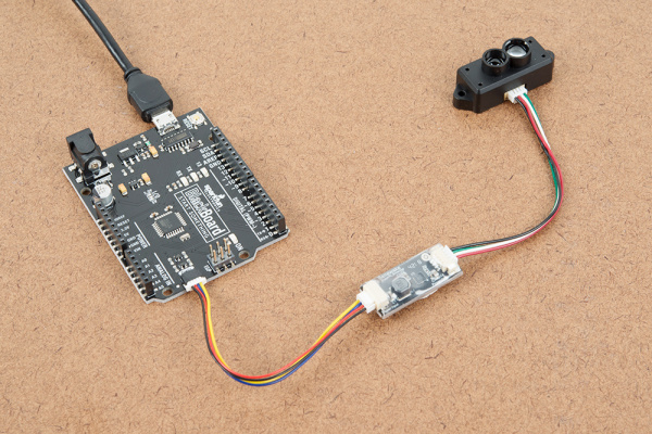
Three Quick Tips About Using U.FL

$
0
0

Three Quick Tips About Using U.FL a learn.sparkfun.com tutorial

Available online at: http://sfe.io/t845

Introduction

Since the number of SparkFun products with wireless or radio-frequency (RF) applications continues to increase we thought it would be helpful to make a crash course in one of the most ubiquitous players: the U.FL connector.

U.FL and the host of compatible connectors (like I-PEX, IPX, or UMCC) are all designed to allow attachment of small coaxial cables that are preferable in wireless applications because of the shielding that the outer conductor provides. We use these connectors because they are small and inexpensive and because the smaller coaxial cables used with them are much easier to deal with. They are, however, a little bit harder to use and more fragile than their larger step-cousin (the SMA connector) so it doesn’t hurt to get a quick primer on how to use them.

This photo shows off both the male and female ends of a U.FL connector. On the left and attached to the cable is the female side while the male side is soldered to the board. (By the way, a connector’s gender is always determined by the gender of the electrical contacts rather than the gender of plastic shrouds or other extraneous materials).

Male and Female U.FL Connectors

In the hands of an eager inventor, exposed U.FLs get plugged/unplugged much more often than those that live deep inside a consumer’s cell phone. A Hirose datasheet shows that they only bothered to test repetitive use to 30 cycles, so follow these tips to keep your connectors working well for as long as possible!

Connect

Caring for your U.FL connector is all about keeping that shiny electrical contact pristine and contacting! Grime, oxidation, and mountain dew will increase the impedance to/from the antenna and will reduce range. Bent contacts won’t let any of the electric pixies through at all and those “it works if I hold it just right” problems are definitely the worst to debug!

Crooked Connection

When connecting the parts of the U.FL, first make sure your finger is relatively clean. To avoid putting pressure on the connection, pinch the cable one or two cm from the end and try to align it so that the female connector rests evenly across the surface of the male connector. You can then lightly put your finger on top of the stacked connectors – if it feels like your elementary school’s old see-saw then try again, you want this to be stable. Also be sure that the two connectors are centered on one another left-to-right and up-to-down when you look at the connector from above the board.

Finger gently holding the connection

If everything is good to go, use the very center of your finger to press firmly down - you’ll feel a satisfying “lock sensation” as the datasheet puts it! (P.S. I had to move my finger off to the side so that you could see the connector in there, but you should really make an effort to push down right in the center of the connector)

The end result should look like this very happy ESP32 LoRa 1-Channel Gateway:

Happily connected U.FL

Protect

You can kind of think of the outside gripping portion of the female U.FL connector as being made out of dragonfly wings - very pretty to look at but also fragile. Putting unnecessary forces on them, for example a torque from pulling the cable in a funky way, could cause them to bend away from the male side of the connector and no longer make a reliable connection. Keeping this from happening should also be a priority when moving a project or creating a final installation.

Torquing a U.FL Connection. No!

Preventing this weird torque is called strain relief and there are a couple ways to do it:

  • Tape down the cable
  • Put the cable through a strain-relief hole on the board (if applicable)
  • Glue down the cable
  • Or think of something else as long as it relieves any forces that might be accidentally applied to the cable

With any of the strain relief methods you should allow the cable to bend naturally to the securing location so as not to transmit any forces or torques to the connector. The ESP32 Gateway has a really convenient channel right below the ESP32 module that you can use to make a tape tent. This keeps the connection nice and secure without having to press down on the cable at all!

Protected U.FL Connection

Disconnect

Inevitably you will want to switch out your lunchbox radio kit antenna for something with a little more pizazz (who doesn’t want a Yagi…) Though tempting (and definitely easy) to just rip the cable off like a band-aid we highly recommend you do not do this. Remember the dragonfly wings? Yup, those outside connectors could be bent enough to make a loose connection or the center pin of the male connector could be bend to the side making it hard to connect the next time. There is actually a ‘specialized’ tool to disconnect these – ain’t nobody got time for that! Instead try using:

  • A pair of tweezers
  • Right angle cutters (whoa there, not too hard!)
  • A flat ‘spudger’ like tool
  • Your imagination (well not directly…)

Here’s a before and after slideshow of the tweezers technique:

Just like when you connected the two halves the name of the game is “torque is lava,” meaning of course that you don’t want to twist the connector as it is coming off. Get a firm (but not crushing) grip on the female connector just below the thick top part (there will be a nice little lip to hold on to as you pull up). Then all you need to do is pull away from the board. When the female part is separate it no longer has the male part to keep the outside contacts from bending inward so be gentle.

Really any tool that can catch the lip underneath the female connector will do the trick. When using these right-angle clippers I just made sure that the thick part of my palm was keeping them open so as not to crush the connector. Then I used my thumb as a fulcrum (the further from the connector the better for a straighter pull) and popped the two halves apart.

Using right-angle clippers

In case you don’t have a two-sided tool you could also try the “spudger” technique. It’s a little harder to get just right but it is also possible to minimize torque on the connector this way. To do it put something thin an rigid underneath the cable and get the tip right up against the barrel of the connector. Now hold down the cable onto the flat thing as close to the connector as possible. If you can, tug the cable directly away from the connector a little (this helps counteract the torque you generate from pulling up from one side only). Finally use your flat rigid piece to lift the connector up and away.

using a board as a spudger

Now you know the basics of how to connect, protect, and disconnect a U.FL connector. Go rule the airwaves!


learn.sparkfun.com | CC BY-SA 3.0 | SparkFun Electronics | Niwot, Colorado

Qwiic Single Relay Hookup Guide

$
0
0

Qwiic Single Relay Hookup Guide a learn.sparkfun.com tutorial

Available online at: http://sfe.io/t832

Introduction

The Qwiic Single Relay is SparkFun’s easiest to use relay yet. The single relay can handle up to 5.5A at 240 VAC for long periods of time. The Qwiic connectors and screw terminals also mean that no soldering is necessary.

SparkFun Qwiic Single Relay

SparkFun Qwiic Single Relay

COM-15093
$11.95

Required Materials

To get started, you’ll need a microcontroller to control everything. You may not need everything though depending on what you have. Add it to your cart, read through the guide, and adjust the cart as necessary.

SparkFun RedBoard - Programmed with Arduino

SparkFun RedBoard - Programmed with Arduino

DEV-13975
$19.95
39
SparkFun ESP32 Thing

SparkFun ESP32 Thing

DEV-13907
$21.95
60
Raspberry Pi 3

Raspberry Pi 3

DEV-13825
$39.95
92
Particle Photon (Headers)

Particle Photon (Headers)

WRL-13774
$19.00
29

Now to get into the Qwiic ecosystem, the key will be one of the following Qwiic shields to match your preference of microcontroller:

SparkFun Qwiic Shield for Arduino

SparkFun Qwiic Shield for Arduino

DEV-14352
$6.95
SparkFun Qwiic HAT for Raspberry Pi

SparkFun Qwiic HAT for Raspberry Pi

DEV-14459
$5.95
1
SparkFun Qwiic Shield for Photon

SparkFun Qwiic Shield for Photon

DEV-14477
$5.95

You will also need a Qwiic cable to connect the shield to your Qwiic Single Relay, choose a length that suits your needs.

Qwiic Cable - 100mm

Qwiic Cable - 100mm

PRT-14427
$1.50
Qwiic Cable - 500mm

Qwiic Cable - 500mm

PRT-14429
$1.95
Qwiic Cable - 200mm

Qwiic Cable - 200mm

PRT-14428
$1.50
Qwiic Cable - 50mm

Qwiic Cable - 50mm

PRT-14426
$0.95

Tools

You will need a flush cutter and wire stripper to remove the sheath and insulation from a cable. A Phillips head screwdriver will be required to connect the load's to a screw terminal.

Self-Adjusting Wire Strippers

Self-Adjusting Wire Strippers

TOL-14872
$16.95
Flush Cutters - Xcelite

Flush Cutters - Xcelite

TOL-14782
$7.95
SparkFun Mini Screwdriver

SparkFun Mini Screwdriver

TOL-09146
$0.95
3

Suggested Reading

If you aren’t familiar with the Qwiic system, we recommend reading here for an overview.

Qwiic Connect System

We would also recommend taking a look at the following tutorials if you aren’t familiar with them.

Serial Communication

Asynchronous serial communication concepts: packets, signal levels, baud rates, UARTs and more!

I2C

An introduction to I2C, one of the main embedded communications protocols in use today.

Serial Terminal Basics

This tutorial will show you how to communicate with your serial devices using a variety of terminal emulator applications.

Qwiic Shield for Arduino & Photon Hookup Guide

Get started with our Qwiic ecosystem with the Qwiic shield for Arduino or Photon.

Hardware Overview

First let’s check out some of the characteristics listed in the relay's datasheet that we’re dealing with, so we know what to expect out of the board.

CharacteristicRange
Operating Voltage1.7V-3.6V
Supply CurrentUPDATE
Coil Resistance23.5Ω
I2C Address0x18 (Default), (Jumper changes to 0x19)
Max Current (Through Relay) 5.5A (240 VAC)

Pins

The following table lists all of the relay’s pins and their functionality.

PinDescriptionDirection
GNDGroundIn
3.3VPowerIn
SDADataBi-directional
SCLClockIn
NCNormally ClosedSwitch
NONormally OpenSwitch
COMSwitch CommonSwitch

Optional Features

The Qwiic Relay has pull up resistors attached to the I2C bus; if multiple sensors are connected to the bus with the pull-up resistors enabled, the parallel equivalent resistance will create too strong of a pull-up for the bus to operate correctly. As a general rule of thumb, disable all but one pair of pull-up resistors if multiple devices are connected to the bus. If you need to disconnect the pull up resistors they can be removed by cutting the traces on the corresponding jumpers highlighted below.

Pull-up Jumper

Pull-up Jumper

The Power LED will light up when the board is powered. The Status LED will light up when the relay has been triggered and the switch is closed, both are highlighted in the below image

Power LED

Power LED

The onboard screw terminal should be used to connect your high-power load, it is highlighted below. The middle COM pin should be hooked up to the Live wire (Usually black) coming from the wall, while NO or NC should be connected to the Live wire on the device side of things.

Screw Terminal

Screw Terminal

Hardware Assembly

If you haven’t yet assembled your Qwiic Shield, now would be the time to head on over to that tutorial. Depending on the microcontroller and shield you’ve chosen, your assembly may be different, but here’s a handy link to the Qwiic Shield for Arduino and Photon Hookup Guide to get you started!

Qwiic Shield for Arduino Photon Hookup Guide

With the shield assembled, SparkFun’s new Qwiic environment means that connecting the relay could not be easier. Just plug one end of the Qwiic cable into the Qwiic Relay, the other into the Qwiic Shield and you’ll be ready to upload a sketch and start turning things on and off. It seems like it’s too easy too use, but that’s why we made it that way!

Connected to Qwiic Shield

SparkFun RedBoard and Qwiic Shield with the Qwiic Relay attached

You’ll also need to place the relay in line with the AC powered item you’re attempting to control. You’ll have to cut your live AC line (usually black or red) and connect one end of the cut wire to COM and the other to NC or NO, depending on what you want the resting state of your device to be. If your AC device is going to be on for most of the time, and you occasionally want to turn it off, you should connect one end to COM and the other to NC. Connect to NO if the device will be off for most of the time. Check out the picture below for a visual aid.

Relay Example Connection

Relay Example Connection

Each relay takes just over 100 mA to power Daisy chaining these boards together on the same bus will result in pretty large power spikes, you may need a separate 3.3V source depending on what else is included in your project

Example Code

Note: This example assumes you are using the latest version of the Arduino IDE on your desktop. If this is your first time using Arduino, please review our tutorial on installing the Arduino IDE.

The Qwiic Relay is pretty simple, so all of the functions to control it are simply contained in the examples, which can be downloaded from the GitHub repo by clicking the button below.

Qwiic Relay Examples (ZIP)

Example 1 - Basic Control

Go ahead and unzip the folder to a directory of your choosing and open up Example1-Basic_control. In this example, we’ll simply have the relay toggle on for 2 seconds, then off for two seconds. Let’s first look at the available functions in our sketch. The first two, relayOn() and relayOff(), are pretty self explanatory, they toggle the relay and return a message to the Serial monitor if no slave is found . The testForConnectivity() function simply tests to see if there is a slave at the proper address (0x18). These functions can be found below.

language:c
void relayOn() {
  Wire.beginTransmission(qwiicRelayAddress);
  Wire.write(COMMAND_RELAY_ON);
  if (Wire.endTransmission() != 0) {
    Serial.println("Check Connections. No slave attached.");
  }
}

void relayOff() {
  Wire.beginTransmission(qwiicRelayAddress);
  Wire.write(COMMAND_RELAY_OFF);
  if (Wire.endTransmission() != 0) {
    Serial.println("Check Connections. No slave attached.");
  }
}

void testForConnectivity() {
  Wire.beginTransmission(qwiicRelayAddress);
  //check here for an ACK from the slave, if no ack don't allow change?
  if (Wire.endTransmission() != 0) {
    Serial.println("Check Connections. No slave attached.");
    while (1);
  }
}

Now that we have these functions declared (Arduino handles prototype declarations for us), we can use them in our void setup() and void loop(). In our setup() function, we simply use the testForConnectivity() function to do just that. We then move on the void loop() where we turn the relay on, wait 2 seconds, turn the relay off, wait two seconds, and repeat. This code from Example 1 is shown below.

language:c
void setup() {
  Serial.begin(9600);
  Serial.println("Qwiic Relay Example 1 Basic Control");
  Wire.begin(); // join the I2C Bus

  testForConnectivity();

}

void loop() {
  relayOn();
  Serial.println("Relay is On.");
  delay(2000);
  relayOff();
  Serial.println("Relay is Off.");
  delay(2000);
}

Opening your serial monitor to a baud rate of 9600 should show something similar to the output below if everything is connected properly. You should also be able to hear the relay clicking on and off. If things aren’t connected properly, you’ll see the message Check connections. No slave attached..

Example 1 Output

Example 1 Output

Example 2 - Change I2C Address

To get started with the second example, open up Example2-Change_I2C_Address In this example, we simply change the address to 0x19. First, let’s take a look at the changeAddress() function, which checks to see if the address is valid (Between 0x07 and 0x78) and changes the relay’s address to that. The function returns true if successful.

language:c
boolean changeAddress(byte address) {
  Wire.beginTransmission(qwiicRelayAddress);
  //check here for an ACK from the slave
  if (Wire.endTransmission()  != 0) {
    Serial.println("Check Connections. No slave found.");
    return (false);
  }

  //check if valid address.
  if (address < 0x07 || address > 0x78) {
    Serial.println("Invalid I2C address");
    return (false);
  }
  //valid address
  Wire.beginTransmission(qwiicRelayAddress);
  Wire.write(COMMAND_CHANGE_ADDRESS);
  qwiicRelayAddress = address;
  Wire.write(qwiicRelayAddress);
  Wire.endTransmission();
  return (true); //Success!
}

Now that we have these functions declared (Arduino handles prototype declarations for us), we can use them in our void setup() and void loop(). In our setup() function, we change the address to 0x19, check to see that the address change was a success, and toggle the relay on and off on this new address. The sketch that handles this is shown below.

language:c
#include <Wire.h>
#define COMMAND_RELAY_OFF                 0x00
#define COMMAND_RELAY_ON                    0x01
#define COMMAND_CHANGE_ADDRESS          0x03

volatile byte qwiicRelayAddress = 0x18;     //Default Address

void setup() {
  Serial.begin(9600);
  Serial.println("Qwiic Relay Master Awake");
  Wire.begin(); // join the I2C Bus

  Wire.beginTransmission(qwiicRelayAddress); // transmit to device
  //check here for an ACK from the slave
  if (Wire.endTransmission() != 0 ) {
    Serial.println("Check Connections. Slave not found.");
  }
  else {
    Serial.println("Qwiic Relay found!");
  }

  boolean error = changeAddress(0x19); // Change the Relay's address to 0x19

  if (error != true) {
    Serial.println("!!!!! invalid address" );
  }
  else {
    Serial.println("success");
  }
}

void loop() { //Toggle the Relay on the new address
  relayOn();
  delay(2000);
  relayOff();
  delay(2000);
}

// changeAddress() takes a 7 bit I2C Address
// and writes it to the Relay. This function
// checks to see if the address is between
// 0x07 and 0x78. If valid, the new address is
// saved to the Relay's EEPROM. If not valid
// address is not changed and is ignored.
// This function returns true if successful and
// false if unsuccessful.
boolean changeAddress(byte address) {
  //check if valid address.
  if (address < 0x07 || address > 0x78) {
    Serial.println("Invalid I2C address");
    return (false);
  }
  //valid address
  Wire.beginTransmission(qwiicRelayAddress);
  Wire.write(COMMAND_CHANGE_ADDRESS);
  qwiicRelayAddress = address;
  Wire.write(qwiicRelayAddress);
  if (Wire.endTransmission() != 0)
  {
    return false;
  }
  return true;
}

// RelayOn() turns on the relay at the SLAVE_ADDRESS
// Checks to see if a slave is connected and prints a
// message to the Serial Monitor if no slave found.
void relayOn() {
  Wire.beginTransmission(qwiicRelayAddress);
  Wire.write(COMMAND_RELAY_ON);
  if (Wire.endTransmission() != 0) {
    Serial.println("Check Connections. No slave attached");
  }
}

// RelayOff() turns off the relay at the qwiicRelayAddress
// Checks to see if a slave is connected and prints a
// message to the Serial Monitor if no slave found.
void relayOff() {
  Wire.beginTransmission(qwiicRelayAddress);
  Wire.write(COMMAND_RELAY_OFF);
  if (Wire.endTransmission() != 0) {
    Serial.println("Check Connections. No slave attached");
  }
}

Example 3 - I2C Scanner

To get started with the third example, open up Example3-I2C_Scanner In this example, we simply scan the I2C bus for devices, useful if we’ve been changing around the address of our relay and have since forgotten what it was. The example comes from Arduino, and the code can be shown below. We basically check for an ACK at each address, and output that address when we get one back.

language:c
#include <Wire.h>

void setup()
{
  Wire.begin();

  Serial.begin(9600);
  while (!Serial);             // Leonardo: wait for serial monitor
  Serial.println("\nI2C Scanner");
}


void loop()
{
  byte error, address;
  int nDevices;

  Serial.println("Scanning...");

  nDevices = 0;
  for (address = 1; address < 127; address++ )
  {
    // The i2c_scanner uses the return value of
    // the Write.endTransmission to see if
    // a device did acknowledge to the address.
    Wire.beginTransmission(address);
    error = Wire.endTransmission();

    if (error == 0)
    {
      Serial.print("I2C device found at address 0x");
      if (address < 16)
        Serial.print("0");
      Serial.print(address, HEX);
      Serial.println("  !");

      nDevices++;
    }
    else if (error == 4)
    {
      Serial.print("Unknown error at address 0x");
      if (address < 16)
        Serial.print("0");
      Serial.println(address, HEX);
    }
  }
  if (nDevices == 0)
    Serial.println("No I2C devices found\n");
  else
    Serial.println("done\n");

  delay(5000);           // wait 5 seconds for next scan
}

Opening your serial monitor to a baud rate of 9600 will show what you have on your I2C bus and should look something like the below image.

I2C Scanner

I2C Scanner

Example 4 - Get Relay Status

The fourth example simply gets the current status of the relay. To get started with this example, open up Example4-Get_Relay_Status. We simply request a byte from the COMMAND_STATUS register on the ATTiny85, and output that byte, this function returns a 1 if the relay is on, 0 if it’s off, and a -1 if there’s an error.

language:c
byte getStatus() {
  Wire.beginTransmission(qwiicRelayAddress);
  Wire.write(COMMAND_STATUS); // command for status
  Wire.endTransmission();    // stop transmitting //this looks like it was essential.

  Wire.requestFrom(qwiicRelayAddress, 1);    // request 1 bytes from slave device qwiicRelayAddress

  while (Wire.available()) { // slave may send less than requested
    char c = Wire.read(); // receive a byte as character.
    if (c == 0x01) return 1;
    else {
      return 0;
    }
  }
}

Opening your serial monitor to a baud rate of 9600 will show you the current status of the relay.

Relay Status

Relay Status

Example 5 - Get Firmware Version

The Qwiic relay is controlled by an ATTiny85. SparkFun gives it some firmware to get it started, this final example shows you how to check which firmware version your ATTiny85 is using. Go ahead and open up Example5-Get_Firmware_Version to get started. Checking out the getFirmwareVersion() function, we see that it requests 2 bytes from the COMMAND_FIRMWARE_VERSION register (0x04) and returns them as a float. We simply call this function in our setup() function to get the firmware version.

Opening your serial monitor to a baud rate of 9600 will show you the current firmware version, and should look something like the below image.

Firmware Version

Firmware Version

Resources and Going Further

Now that you’ve successfully got your Qwiic Single Relay up and running, it’s time to incorporate it into your own project!

For more information, check out the resources below:

Need some inspiration for your next project? Check out some of these related tutorials using relays. Be sure to check your current rating when handling the Qwiic Single Relay when browsing some of the other tutorials using relays.

Photon Remote Water Level Sensor

Learn how to build a remote water level sensor for a water storage tank and how to automate a pump based off the readings!

Blynk Board Project Guide

A series of Blynk projects you can set up on the Blynk Board without ever re-programming it.

ESP8266 Powered Propane Poofer

Learn how Nick Poole built a WiFi controlled fire-cannon using the ESP8266 Thing Dev Board!

Blynk Board Bridge Widget Demo

A Blynk project that demonstrates how to use the Bridge widget to get two (or more) Blynk Boards to communicate.

Beefcake Relay Control Hookup Guide

This is a guide for assembling and basic use of the Beefcake Relay Control board

How to Build a Remote Kill Switch

Learn how to build a wireless controller to kill power when things go... sentient.

IoT Power Relay

Using the ESP32 to make a web-configured timed relay.
New!

Qwiic Quad Relay Hookup Guide

SparkFun’s Qwiic Quad Relay is a product designed for switching not one but four high powered devices from your Arduino or other low powered microcontroller using I2C.

learn.sparkfun.com | CC BY-SA 3.0 | SparkFun Electronics | Niwot, Colorado

Qwiic Quad Relay Hookup Guide

$
0
0

Qwiic Quad Relay Hookup Guide a learn.sparkfun.com tutorial

Available online at: http://sfe.io/t839

Introduction

SparkFun’s Qwiic Quad Relay is a product designed for switching not one but four high powered devices from your Arduino or other low powered microcontroller using I2C. It has four relays rated up to 5 Amps per channel at 250VAC or 30VDC that are controlled by an ATtiny84A. Each channel has its own blue stat LED, silk for easy identification, and screw terminals for easy connection. The product is Qwiic enabled allowing you to easily integrate the Quad Relay with other products in the Qwiic environment, which means no solder neccessary!

SparkFun Qwiic Quad Relay

SparkFun Qwiic Quad Relay

COM-15102
$29.95
Before we begin! There are a number of safety precautions included in the product, but that can not account for human inexperience and error. This product and the example below interacts with HIGH AC voltage and so is intended for people experienced around, and knowledgeable about HIGH AC voltage. If that's not quite your jam, then take a look at our IoT Power Relay! It's not I2C but the IoT Power Relay contains shielding to prevent accidental shock.

Required Materials

For the example under Hardware Assembly, I used the following materials. You may not need everything though depending on what you have. Add it to your cart, read through the guide, and adjust the cart as necessary.

Jumper Wires - Connected 6" (M/M, 20 pack)

Jumper Wires - Connected 6" (M/M, 20 pack)

PRT-12795
$1.95
2
Qwiic Cable - 100mm

Qwiic Cable - 100mm

PRT-14427
$1.50
Wall Adapter Power Supply - 5V DC 2A (Barrel Jack)

Wall Adapter Power Supply - 5V DC 2A (Barrel Jack)

TOL-12889
$5.95
15
SparkFun BlackBoard

SparkFun BlackBoard

SPX-14669
$14.95
5
Tactile Button Assortment

Tactile Button Assortment

COM-10302
$5.85
5
Breadboard - Mini Modular (Red)

Breadboard - Mini Modular (Red)

PRT-12044
$3.95

Additional Options

You could also use our 9 volt wall adapter if that suits your fancy and we have a number of Qwiic cable sizes to fit your needs.

Wall Adapter Power Supply - 9VDC 650mA

Wall Adapter Power Supply - 9VDC 650mA

TOL-00298
$5.95
9
Qwiic Cable - 100mm

Qwiic Cable - 100mm

PRT-14427
$1.50
Qwiic Cable - 500mm

Qwiic Cable - 500mm

PRT-14429
$1.95
Qwiic Cable - 200mm

Qwiic Cable - 200mm

PRT-14428
$1.50
Qwiic Cable - 50mm

Qwiic Cable - 50mm

PRT-14426
$0.95

Suggested Reading

If you aren’t familiar with the Qwiic system, we recommend reading here for an overview.

Qwiic Connect System

We would also recommend taking a look at the following tutorials if you aren’t familiar with them.

Serial Communication

Asynchronous serial communication concepts: packets, signal levels, baud rates, UARTs and more!

I2C

An introduction to I2C, one of the main embedded communications protocols in use today.

Hardware Overview

Power

There are two separate power systems on the Quad Relay: a 5V system that powers the relays and a 3.3V system that powers the on board ATtiny84A and interfaces with a microcontroller through the four pin header or Qwiic connector.

The on board barrel jack takes a power source in a range of 7-15V. It regulates the voltage and supplies power to the 5V power system of the relays. If your wall adapter or power source is at 5 volts like our 5V/2A Wall adapter then you can close the jumper on the underside of the product labeled 5V Wall Adapter (see Jumpers section below), and this will allow you to sidestep the on board regulator to power the 5V system directly. If you decide to go with a higher voltage wall adapter, be cognizant that the voltage regulator will start to heat up. With all the relay channels turned on the Quad Relay will pull ~250mA of current and at 9 Volts, that’s 2.25 Watts of power (mathematical!). Over time the regulator will get hot, but will remain functional. I suggest that if you expect to have all relay channels on for extended periods of time, that you go with a 5V power supply.

Input Power Barrel Jack

To provide 3.3V to the on board ATtiny84A you can use the plated through hole labeled 3V3 on the four pin header. Alternatively, you can plug a Qwiic connector into one of the two Qwiic connectors.

PTH Pins and Qwiic Connectors for Power

Relays

There are four single pole, double throw JZC-11F relays on the Qwiic Quad Relay. Each relay is capable of 5 Amps at 250VAC or 30VDC. These relays have an associated blue screw pin terminals that are aligned in order from left to right.

alt text

LEDs

There is a red power LED labeled PWR that indicates power from the barrel jack. There is also a blue stat LED for each relay labeled with their respective number 1-4.

Relays and Screw Terminals

Jumpers

There are two jumpers on the underside of the Qwiic Quad Relay. The first is the address jumper that changes the default I2C address from 0x6D to 0x6C. The second is the jumper labeled 5V Wall Adapter Jumper. If you intend to use a wall adapter or other power source that is below 7-15V than you can close this jumper to side step the on board voltage regulator, and provide 5V directly to the 5V power system.

Jumper Pads

Qwiic Connectors

The Qwiic connectors allow you to integrate easily into our Qwiic environment and allows you to prototype without the need for soldering! The 3.3V provided by the Qwiic connector will power the on board ATtiny84A. If you do not power the 3.3V power system this way, you can still provide power through the four pin header.

Qwiic Connectors

Safety Considerations

This product is designed to switch high power AC or DC and so has some inherent dangers. We’ve done our best to implement safety features directly into the design. To begin, the copper ground pour for the ATtiny84A circuitry is restricted to an area apart from the relays. In regards to the microcontroller, there are opto-isolators that isolate the 3.3V power system that it utilizes from the 5V power system of the relays. Next, the common pin of the relays have an air gap surrounding the pin on three sides to prevent any high voltage arcing. Finally, the traces on the relays are extra wide to handle the high amperage carrying potential of the relays.

Hardware Assembly

Introduction

Let’s walk through how to setup the relay to switch on a lamp or other device, but let’s begin with a short intro into relays. A relay is a switch. However unlike most switches, within the relay’s housing there is also a switching mechanism that is isolated from the switch. This is the relay’s defining feature because this separation between switching mechanism and switch, as well as the switching mechanism’s low power requirements, allows for low power micro-controllers to activate the switching mechanism without interfacing with whatever is getting “switched”. Shmow-zow!

We have three channels per relay broken out to blue screw pin terminals. The channels are labeled for their function. One is considered normally open or NO, the next channel is common or COM, and the final is normally closed or NC. The names explain the state of the channel with relation to the switch at rest. The normally closed channel is where the switch sits before the switching mechanism has been activated and conversely the normally open channel is where the switch would sit after. The common channel is, as the name implies, what the other two channels have in common. This is known as a single pole, double throw switch (SPDT). The image below helps to illustrate this characteristic of our particular relay.

SPDT Switch

When the switching mechanism is activated the thicker bar in the image above that connects normally closed to common flips over to connect normally open and common.

Assembly

Onto the assembly. First I’m using a BlackBoard for it’s Qwiic capabilities and it’s powered via micro-USB. I have a button plugged into a breadboard, straddling the gap in the center, and jumper wires connecting it to pin 2 and GND on the blackboard.

BlackBoard with Button and Qwiic Cable

On the tail end is a Qwiic connector leading to the Quad Relay.

Let’s take a quick look at the lamp wire, before we look at the Quad Relay. Our goal here is to sever one of the two lamp wires, and plug the two ends of the cut wire into the relay which will reconnect the wire when we activate the switching mechanism. First, I’ve cut one of the two wires as shown to create a break in the connection.

Cutting Cable

I then peeled the wire apart and stripped the two ends.

Strip Wire Ends

We’ll put one end our wire in the COM channel, and the other we’ll have to decide upon. For this project we want our switch to act intuitively: when you activate the switching mechanism, the light switches on. There could be a case where you want the switching mechanism activated as its “rest” state. Since we’re going with a more normal approach we’ll cut our wire and place one end in common and the other in the normally open channel. Now when we activate the switching mechanism, the severed wire will be reconnected when the switch flips to the normally open channel connecting it and the common channel.

For the quad relay I’m powering the 5V system (the relays), with a 5V Wall Adapter, and the 5V Wall Adapter jumper closed underneath. The Qwiic cable from the black board is providing power to the 3.3V system as seen at the top of the picture below, and we have the lamp cable plugged into and the screw terminals tightened down on channels COM and NO.

Connection on Qwiic Quad Relay Side

Now that our hardware is all set up, let’s take a look at the code that turns the lamp on.

Example Code

Note: This example assumes you are using the latest version of the Arduino IDE on your desktop. If this is your first time using Arduino, please review our tutorial on installing the Arduino IDE.

Let’s take a look at some example code fort the Qwiic Quad Relay. You can download all example codes from the GitHub repo by clicking the link below.

Qwiic Quad Relay Example Code (ZIP)

Example 1 - Relay Control

This is the code used for the lamp example above. Unzip and open up example one under Qwiic_Quad_Relay-master>Example Code>Example1_Relay_Control to follow along. At the top, let’s break down the defines that are provided. While all of them might not be necessary for your project and they weren’t for the lamp example, they are still displayed here to elucidate the functionality of the Quad Relay. First the default address 0x6D is included and it’s followed by the second I2C address 0x6C, which is commented out. If you’d rather use the latter then close the jumper on the underside of the product labeled ADDR.

language:c
#include <Wire.h>

#define RELAY_ADDR 0x6D // Default address - open jumper. 
//#define RELAY_ADDR 0x6C // Address when jumper is closed.

The rest of the defines list all of the possible I2C commands possible. You can toggle each individual relay, toggle them all, turn them all on, or turn them all off. There is also a list of commands to check the state of each relay; whether the relay is on or off represented numerically by zero and 15 respectively.

language:c
// Here are the commands to turn on and off individual relays. 
#define TOGGLE_RELAY_ONE 0x01
#define TOGGLE_RELAY_TWO 0x02
#define TOGGLE_RELAY_THREE 0x03
#define TOGGLE_RELAY_FOUR 0x04

// Here are the commands to turn them all off or on. 
#define TURN_ALL_ON  0xB 
#define TURN_ALL_OFF 0xA

//Here is the command to toggle every relay.
#define TOGGLE_ALL 0xC 

// Here are the commands to check on the 'status' of the relay i.e. whether the
// relay is on or off.
#define RELAY_ONE_STATUS 0x05
#define RELAY_TWO_STATUS 0x06
#define RELAY_THREE_STATUS 0x07
#define RELAY_FOUR_STATUS 0x08

//Four buttons
const uint8_t yellow_btn = 2;
const uint8_t blue_btn = 3;
const uint8_t red_btn =  4;
const uint8_t green_btn =  5;

Let’s move on. In the following code, we define four buttons that when pressed, will send an I2C command to the associated relay. We have a small delay for debounce of 400 milliseconds associated with each button press. In the setup is a call to a function that gets the status of the relays: On or Off represented by zero and 15 respectively. This is detailed more extensively just after the next code block.

language:c
void setup()
{
  Wire.begin(); 
  Serial.begin(115200);

    //Use internal resitors to keep them in a known high state. 
  pinMode(yellow_btn, INPUT_PULLUP);
  pinMode(blue_btn, INPUT_PULLUP);
  pinMode(red_btn, INPUT_PULLUP);
  pinMode(green_btn, INPUT_PULLUP);

  get_relays_status();
}

void loop()
{
    // Since we'll only ever want the relay to be on or off,
    // the logic is handled by the product. Here we're just pressing buttons and
  // putting a small 400 ms debounce. 

    //button one, relay one!
  if(digitalRead(yellow_btn) == LOW){
    Serial.println("Yellow Button");
    Wire.beginTransmission(RELAY_ADDR);
    Wire.write(TOGGLE_RELAY_ONE);
    Wire.endTransmission();
        delay(400);
  }

    //button two, relay two!
  if(digitalRead(blue_btn) == LOW){
    Serial.println("Blue Button");
    Wire.beginTransmission(RELAY_ADDR);
    Wire.write(TOGGLE_RELAY_TWO);
    Wire.endTransmission();
        delay(400);
  }

    //button three, toggle every relay: on -> off and off -> on.
  if(digitalRead(red_btn) == LOW){
    Serial.println("Red Button");
    Wire.beginTransmission(RELAY_ADDR);
    Wire.write(TOGGLE_ALL);
    Wire.endTransmission();
        delay(400);
  }

    //button four, turn off all the relays!
  if(digitalRead(green_btn) == LOW){
    Serial.println("Green Button");
    Wire.beginTransmission(RELAY_ADDR);
    Wire.write(TURN_ALL_OFF);
    Wire.endTransmission();
        delay(400);
  }
}

The get_relays_status function is of particular interest. Getting the status of the relays works like an I2C buffer. Depending on the number of bytes requested, you will get the status of that many relays. For example, if you request the status of relay one and four bytes, then you’ll get the status of relay one plus the other three. If you request relay one and two bytes, then you’ll get the status of relay one and two. If you request the status of relay three and three bytes, then you’ll get the status of relay three, relay four, and relay one.

language:c
void get_relays_status(){
  int i = 1; 
  Wire.beginTransmission(RELAY_ADDR);
  // Change the Wire.write statment below to the desired relay you want to check on.
  Wire.write(RELAY_ONE_STATUS); 
  Wire.endTransmission();
  //  We want the states of all the relays so we're requesting four bytes, i.e.
  //  four relays. If you request 2 bytes, it will give you the state of two relays! 
  Wire.requestFrom(RELAY_ADDR, 4); 

  // Print it out, 0 == OFF and 15 == ON.  
  while(Wire.available()){
    Serial.print("Relay "); 
    Serial.print(i); 
    Serial.print(": "); 
    Serial.println(Wire.read());
    i++;
  }

}

Let There Be Light!

When we load up the code, and press the button we should see the relay one LED light up.

Qwiic Quad Relay Powered

If your relay LED is on and the lamp doesn’t turn on, make sure you have the lamp turned on. We’ll let the relay handle turning it off and on from now on. Now if all is correctly assembled:

Quad Relay in Action

Algebraic!!

Resources and Going Further

Now that you’ve successfully got your SparkFun Qwiic Quad Relay up and running, it’s time to incorporate it into your own project!

For more information, check out the resources below:

Need some inspiration for your next project? Check out some of these other awesome related tutorials using relays. Be sure to check your current rating when handling the Qwiic Single Relay when browsing some of the other tutorials using relays.

Photon Remote Water Level Sensor

Learn how to build a remote water level sensor for a water storage tank and how to automate a pump based off the readings!

Blynk Board Project Guide

A series of Blynk projects you can set up on the Blynk Board without ever re-programming it.

ESP8266 Powered Propane Poofer

Learn how Nick Poole built a WiFi controlled fire-cannon using the ESP8266 Thing Dev Board!

Blynk Board Bridge Widget Demo

A Blynk project that demonstrates how to use the Bridge widget to get two (or more) Blynk Boards to communicate.

Beefcake Relay Control Hookup Guide

This is a guide for assembling and basic use of the Beefcake Relay Control board

How to Build a Remote Kill Switch

Learn how to build a wireless controller to kill power when things go... sentient.

IoT Power Relay

Using the ESP32 to make a web-configured timed relay.
New!

Qwiic Single Relay Hookup Guide

Get started switching those higher power loads around with the Qwiic Single Relay.

learn.sparkfun.com | CC BY-SA 3.0 | SparkFun Electronics | Niwot, Colorado

RedBoard Qwiic Hookup Guide

$
0
0

RedBoard Qwiic Hookup Guide a learn.sparkfun.com tutorial

Available online at: http://sfe.io/t844

Introduction

The SparkFun RedBoad Qwiic is the newest edition of the Arduino-compatible development platforms in the SparkFun catalog. This updated version of the classicSparkFun RedBoard incorporates a few key improvements over its predecessor (see Hardware Overview). However, like the original SparkFun RedBoard, it is designed to be an easy-to-use learning platform for coding, physical computing, and project prototyping. These skills are becoming increasingly significant in today’s education and the technological community.

SparkFun RedBoard Qwiic

SparkFun RedBoard Qwiic

DEV-15123
$19.95

This tutorial aims to familiarize you with the new SparkFun RedBoad Qwiic and help you get started using it. To begin, we will go over the hardware and features of the board. Next, this we’ll guide you through the installation of the Arduino IDE (Integrated Development Environment) software, the main user interface for programming the board. Finally, we will walk you through a few examples using the Arduino IDE.

The SparkFun RedBoad Qwiic can interact with real-world sensors, control motors, display information, and perform near-instantaneous calculations. It enables anyone to create unique, nifty projects from something as simple as displaying characters on an LCD display or detecting changes in light to vastly more complicated projects like an IoT cellular device (Not recommend for beginners… start with something simpler and work your way up.). If you’re familiar with how the original SparkFun RedBoard worked, you may want to skim over parts of this tutorial.

Required Materials/ Tools

To get started, all you need is a few things:

  • SparkFun RedBoad Qwiic - You definitely need this; otherwise, you are on the wrong tutorial page.
  • USB micro-B Cable - 6 Foot - The USB interface serves two purposes: it powers the board and allows you to upload programs to it.
  • Computer with the Arduino IDE installed on it - That is how we will program the board and interface with it.
    Troubleshooting Tip: If you are not a technical or computer savy individual and you have your choice of computers, a Windows 7 or 10 computer is highly recommended. You will usually run into the the least issues, if any, with these operating systems.

That is ALL… pretty simple right? Now you won’t be able to do much since there are no additional sensors to interact with the physical world. However, you can at least blink an LED and do some math calculations.

Click the buttons above to toggle the additional materials based on the tasks you
wish to perform. Feel free to modify the items in your cart to fit your needs.

Jumper Modification

If you would like to modify the 3.3V/5V I/O jumper or A4/A5 Qwiic connector jumpers, you will need soldering equipment and/or a knife.

Solder Lead Free - 100-gram Spool

Solder Lead Free - 100-gram Spool

TOL-09325
$7.95
7
Weller WLC100 Soldering Station

Weller WLC100 Soldering Station

TOL-14228
$44.95
Chip Quik No-Clean Flux Pen  - 10mL

Chip Quik No-Clean Flux Pen - 10mL

TOL-14579
$7.95
1
Hobby Knife

Hobby Knife

TOL-09200
$2.95
2

Qwiic Example

If you would like to follow along with the examples below to interact with the physical world, you will also need the following items:

SparkFun Distance Sensor Breakout - 4 Meter, VL53L1X (Qwiic)

SparkFun Distance Sensor Breakout - 4 Meter, VL53L1X (Qwiic)

SEN-14722
$21.95
3
Qwiic Cable - 100mm

Qwiic Cable - 100mm

PRT-14427
$1.50

Suggested Reading

The SparkFun RedBoad Qwiic aims to be a beginner-friendly microcontroller platform. You can get started without an innate knowledge of Ohm’s Law or How Electricity Works (but a little understanding wouldn’t hurt!). The following are some subjects you should be familiar with; however, to use the more advanced features of the board, it is recommended that you read up on the Logic Levels and I2C tutorials.

What is a Circuit?

Every electrical project starts with a circuit. Don't know what a circuit is? We're here to help.

What is an Arduino?

What is this 'Arduino' thing anyway?

Logic Levels

Learn the difference between 3.3V and 5V devices and logic levels.

I2C

An introduction to I2C, one of the main embedded communications protocols in use today.

One of the new, advanced features of the board is that it takes advantage of the Qwiic connect system. We recommend familiarizing yourself with the Logic Levels and I2C tutorials (above) before using it, as all Qwiic sensors utilize an I2C communication protocol.

Qwiic Connect System
Fun Fact: Qwiic is a play on words between "quick" and I2C or "iic".

Installing Drivers

The SparkFun RedBoard Qwiic uses a USB-to-Serial adapter based on the CH340C IC from WCH. The driver for the CH340C chip should automatically install on most operating systems. The driver allows your computer to recognize the SparkFun RedBoard Qwiic as a device and lets it communicate with the board over the USB connection.

The SparkFun RedBoard Qwiic has been tested on Windows 7, Windows 10, Mac OSX High Sierra, and Raspbian Stretch (11-13-2018 release) for the Raspberry Pi. However, there is a wide range of operating systems out there; you may need to manually install your driver or delete/uninstall your old driver before updating to the new driver. We’ve also written a separate SparkFun Serial Basic CH340C Hookup Guide in case you run into issues.

Click the buttons above for further instructions on verifying
that your computer recognizes your board or updating your old drivers.

Driver Verification

To verify that your driver is working, you should see the difference in the following pictures after plugging in your SparkFun RedBoard Qwiic. Alternatively, once you have the Arduino IDE installed, you should also see a change in the number of available Serial/COM Ports (you may need to restart the Arduino IDE for the board to populate).

Windows

Check that the board shows up in your device manager. You can click the Start or (Windows) button and type "device" to quickly search for the application. (*On Windows 10, the quick search function is picky on the spelling of the application you are searching for. For example, you may get results using "devi" and none for "device".)

Windows 10 Device Manager Window
Screenshot of Window 10 Device Manager with RedBoard (Qwiic) on COM42. Click to enlarge.

Mac OSX

Open the Terminal and run the following command "ls /dev/cu*" in the Terminal and check for the following changes (your board may show up under a different device name). To open the Terminal, open your Applications folder, Utilities folder, then double-click on Terminal. Otherwise, press (Command) + space bar (Space Bar) to launch Spotlight and type "Terminal," then double-click the search result.

Mac OSX CLI Command Entry
Screenshot of Mac OSX terminal with RedBoard (Qwiic) on cu.wchusbserialfd1410. Click to enlarge.

ls /dev/cu*
Note: If you are still unsure of how to access the Terminal, watch this video or read this Apple support article.

Raspbian

Run the following command "ls /dev/ttyUSB*" in the CLI/Terminal and check for the following changes (your board may show up under a different device name).

Raspbian CLI Command Entry
Screenshot of Raspberry Pi CLI with RedBoard (Qwiic) on ttyUSB0. Click to enlarge

ls /dev/ttyUSB*

Updating Drivers

The CH340C is made by WCH. You can find the latest version of their drivers here, but most of their pages are in Mandarin. If you use a Chrome web browser, you should have the option to have the web page translated.

If you have the older CH340 drivers installed, you may need to update them. Below are the instructions for doing so on each of the tested operating systems:

Windows 7/10

Download and run the executable. Click the "Uninstall" button first, followed by the "Install" button.

Win 10 Installation Screenshot
Windows CH340 Driver Installation

Mac OSX

Run the following commands in the CLI/Terminal before installing the new drivers:

rm -rf /System/Library/Extensions/usb.kext
rm -rf /System/Library/Extensions/usbserial.kext
Note:
To open the Terminal, open your Applications folder, Utilities folder, then double-click on Terminal. Otherwise, press (Command) + space bar (Space Bar) to launch Spotlight and type "Terminal," then double-click the search result.

If you are still unsure of how to access the Terminal, watch this video or read this Apple support article.
Download and extract the folder. Then, open the ".pkg" file from the unzipped folder.

Mac OSX Installation Screenshot
Mac OSX CH340 Driver Installation File

Raspbian

Run the following commands in the CLI/Terminal:

sudo apt-get upgrade
sudo apt-get update

Other Linux Distributions

Unfortunately, I do not have a Linux computer to test with, but here is the downloadable .zip folder for the CH340 driver.

Installing the Arduino IDE

Download/Install Arduino

You can download the Arduino IDE from their website. They have installation instructions, but we will also go over the installation process as well. Make sure you download the version that matches your operating system.

Click for Arduino IDE Download Page

The installation procedure is fairly straightforward, but it does vary by OS. Here are some tips to help you along. We’ve also written a separate Installing Arduino tutorial in case you get stuck.

Troubleshooting Tips:
  • We recommend using a computer with a full desktop operating system like Windows 7/10 (avoid Windows 8 if you can), Mac OSX, and certain flavors Linux (check the Arduino FAQ page for compatibility).

    • If you are not a technical or computer savy individual and you have your choice of computers, I highly recommend using a Windows 7 or 10 computer. You will usually run into the the least issues, if any, with these operating systems.

  • We do NOT recommend using a Chromebook, Netbook, tablet, phone, or the Arduino Web IDE in general. You will be responsible for troubleshooting any driver or Arduino Web IDE issues.

  • As of writing this tutorial (12-14-2018), the most recent and stable release of the Arduino IDE is version 1.8.5. We recommend using that version of the Arduino IDE; you can download the previous releases here.

  • On Windows 10, we do NOT recommend installing the Arduino IDE from the app store. You may run into issues because the OS will automatically update to the most recent release of the Arduino IDE, which may have unknown bugs (like the compiler errors in versions 1.8.6 and 1.8.7).

  • Raspberry Pi users with Raspbian installed should use the Linux ARM download. We do not recommend using the command line installation. It will install the oldest release of Arduino, which is useless when it comes to installing new boards definitions or libraries.

  • For additional troubleshooting tips, here is a troubleshooting guide from Arduino.

Click the buttons above for OS specific instructions.

Windows Install Tips

The Windows version of Arduino is offered in two options: an installer or a zip file. The installer is the easier of the two options, just download that, and run the executable file to begin the installation.

Windows 10- Arduino Installation Diagram
Windows install steps. Click the image to get a bigger view.

When you're prompted to install a driver during installation, select "Install". This will install drivers for Arduino specific boards (like the Uno, Nano, etc.) that you may use in the future.

  • If you choose to download the zip file version of Arduino, you'll need to extract the files yourself. Don't forget which folder you extract the files into! You will need to run the executable Arduino file in the folder to start the Arduino IDE.

  • On Windows 10, there is an option to install Arduino through their app store. we do not recommend installing the Arduino IDE from the app store. You may run into issues because the OS will automatically update to the most recent release of the Arduino IDE, which may have unknown bugs.

Mac Install Tips

The Mac download of Arduino is only offered in a zip file version. After the download is finished, simply double-click the .zip file to unzip it.

Mac Install Screenshot
Mac OSX Arduino.app

Following that, you'll need to copy the Arduino application into your applications folder to complete the installation.

Linux Install Tips

As Linux users are no doubt aware, there are many flavors of Linux out there, each with unique installation routines. Check out the FAQ section of the Arduino webpage for more details. Otherwise, you can also use the Linux section of our Installing Arduino tutorial for some helpful links for an assortment of Linux distributions.
Raspbian Stretch
Raspberry Pi users with Raspbian installed should use the Linux ARM download. Do not use the command line installation process. For more information, please refer to this blog post from Arduino.
Ubuntu and Debian
For Ubuntu and Debian users, installing Arduino should only need a simple "apt-get" command like:

sudo apt-get update && sudo apt-get install arduino arduino-core
Other Distributions
Other Linux distros aren't too dissimilar from the Ubuntu and Debian instructions.

With Arduino downloaded and installed, the next step is to plug the board in and test it out! Pretty soon you’ll be blinking LEDs, reading buttons, and doing some physical computing!


Hardware Overview

Below is an annotated image, and an overview of all of the important features for the SparkFun RedBoard Qwiic:

Annotated image of RedBoard

Click the buttons below for more details.

New Features

The new features of the SparkFun RedBoard Qwiic include:
  • An updated Serial-USB Converter Chip
  • An improved AP2112 Voltage Regulator
  • A Qwiic Connector
  • Available A4/A5 Jumpers
  • Available Voltage Level Jumpers
  • An improved Reset Button
  • RX/TX LED color change
Annotated image of new features
New features of RedBoard Qwiic.

Serial-USB Converter Chip

The new CH340C IC allows the SparkFun RedBoard Qwiic to utilize the USB micro-B connection and should reduce the need for users to manually install drivers. Newer operating systems should automatically recognize and install the drivers for the board.

AP2112 Voltage Regulator

The AP2112 is a more robust 3.3V regulator to provide more power to daisy chain multiple Qwiic devices. Unlike the MIC5205, which could only source about 150mA of current; the AP2112 can source up to 600mA of current and should be able to handle most of your Qwiic device needs.

Qwiic Connector

This connector allows the SparkFun RedBoard Qwiic to seamlessly interface with SparkFun's Qwiic Ecosystem.

A4/A5 Jumpers

Pins A4 and A5 are tied directly to the I2C bus. These jumpers can be used to disconnect the logic level converters from pins A4 and A5 so that they might be used independently from the Qwiic system for analog readings.

Voltage Level Jumpers

These jumpers allow users to easily switch from a 3.3V to 5V board. This allows the user to convert the board (and I/O pins) to either 3.3V or 5V based on their needs. Unlike the the originalSparkFun RedBoard, you no longer need a logic level converter to interface directly to a 3.3V device or sensor.

Reset Button

The board also includes a new, more pronounced reset button that is easier to push. Anyone with "fat fingers" can relate to this struggle.
Reset Button Comparison
The more ergonomic reset button that is easier to press.

RX/TX LEDs

The TX LED is now green, instead of yellow and the RX LED is now yellow, instead of red.

Dimensions

The dimensions for the board are approximately 2.7" x 2.1". The board uses female headers laid out in a standard configuration for Arduino shields. The barrel jack for power uses a standard 5.5mm outer diameter and 2.1mm inner diameter mating connection. The Qwiic connector uses a 4-pin JST SH type connector. There are also 4 mounting points on the board.

RedBoard Qwiic Dimensions
Screen shot of RedBoard Qwiic board layout in Eagle. (Click image to enlarge.)

For the more details on the board sizing and component placement please refer to the Eagle files provided.

Download Eagle Files (ZIP)

Eagle is a free for educators, makers, and hobbyists (i.e. basically, anything not for commercial purposes). All measurements are accurate, excluding any manufacturing tolerances. (Unfortunately, we do not have this information available; you may need to just measure the board you purchase.)

Microcontroller

The microcontroller (ATmega328 IC) is the work horse of the SparkFun RedBoard Qwiic. The ATmega328 is an 8-bit AVR microcontroller manufactured by Atmel, now Microchip. Once an Arduino sketch is uploaded to the board, the program is stored in the memory of the ATmega328. The microcontroller will then run/execute the program while the SparkFun RedBoard Qwiic is powered.

ATmega328
Image of the ATmega328 IC.

Clock

An external 16 MHz crystal is used as the clock for the ATmega328.

Memory

The ATmega328 has Flash, SRAM (Static Random Access Memory), and EEPROM (Electrically Erasable Programmable Read-Only Memory) memory.

  • 32KB Flash Memory - where the Arduino sketch/program is stored (including the 512 byte Optiboot bootloader).
  • 2KB SRAM - where the sketch/program creates and manipulates variables when it runs.
  • 1KB EEPROM - is available for stable long-term storage (read/written with the EEPROM library).
The Flash and EEPROM memory are non-volatile; the data is still stored even when the board is no longer powered. The SRAM, on the other hand, is volatile and the data is only available while the board is powered.

Troubleshooting Tips:
  • The EEPROM can be corrupted with low power/brown out issues.
  • When you run out of SRAM, the sketch may fail or act strangely after it is uploaded. If you suspect this is the issue, try to comment out any long strings or large data structures. If the sketch starts to run normally, then you may need to modify your data requirements.

Bootloader

The Optiboot bootloader is a unique piece of firmware (512 bytes) at the end of the address space of the flash memory. The Optiboot bootloader is specifically configured for the ATmega328 to interface with the Arduino IDE, through a serial interface, to upload code. Without a bootloader, you would need to external programmer and program the microcontroller through the SPI interface (specifically, the ISP/ICSP headers).

For more details on the ATmega328, memory, and the bootloader check out these tutorials: You can also find the datasheet for the ATmega328 from the Microchip product page.

Power/Reset

The SparkFun RedBoard Qwiic can be powered via the USB and/or barrel jack connectors. If you choose to power it via USB, the other end of the USB cable can be connected to either a computer or a 5V (regulated)USB wall charger. Otherwise, should you choose to use the barrel jack, any wall adapter connected to this jack should supply a DC voltage between 7 and 15V.

Annotated image of power features
Annotated image of RedBoard Qwiic with power and reset features highlighted.

Power LED Indicator

Just to the right of the word RedBoard on your circuit board, there’s a tiny LED next to the word ON. This green LED should light up whenever you plug your Arduino into a power source. If this light doesn’t turn on, there’s a good chance something is wrong.

Reset Button

Just like the original Nintendo, the Arduino has a reset button. Pushing it will temporarily connect the reset pin to ground and restart any code that is loaded on the Arduino. This can be very useful if your code doesn’t repeat, but you want to test it multiple times. Unlike the original Nintendo however, blowing on the Arduino doesn’t usually fix any problems.
Reset Button Comparison
This updated version of the RedBoard has a more ergonomic reset button that is easier to press.

Barrel Jack for VIN

The barrel jack accepts a male, center-positive connector with a 5.5mm outer diameter and 2.1mm inner diameter. Check out this tutorial for more information on power connectors.

Our 9V and 12V power adapters are good choices if you're looking to power the board through the barrel jack. Any wall adapter connected to this jack should supply a DC voltage between 7 and 15V as specified by the electrical characteristics of the LM1117 voltage regulator used on the board. The input voltage pin VIN on the power headers is directly connected to the input voltage of the barrel jack.

Troubleshooting Tips:
The board could operate on an external supply of 6 to 20 volts, but the recommended range is 7 to 12 volts. (*If supplied with less than 7V, the 5V pin may supply less than five volts and the board may be unstable. Using more than 12V, the voltage regulator may overheat and damage itself and/or the board.)

For more technical details about voltage regulators and thermal dissipation, I suggest taking a look at these blog posts and tutorial:

USB

A USB micro-B cable is usually the easiest way to power the board, especially when you're programming it because the USB interface is required for uploading code too. A traditional USB port supplies a regulated 5V, but is limited to about 500mA (USB 2.0). Additionally, there is a fuse that protects your computer from shorts and overcurrent. If more than ~750mA is drawn through the USB port, it automatically throttles the current draw or disconnects power until the short/overload is removed. If you need more than that a barrel jack wall adapter is the best choice.
USB connection example
An example of how to pull USB cable straight out.
Troubleshooting Tip:
Users should take care NOT to pry or leverage on the connector when inserting/removing the USB cable. Doing so, WILL damage the board and cause the pads and/or traces to tear off as well. The cable should be removed by pulling straight outwards from the board.

The fuse can also be tripped with a high current draw and high ambient temperatures.

AP2112 Voltage Regulator

The AP2112 is a more robust 3.3V regulator to provide more power to daisy chain multiple Qwiic (I2C) devices. Unlike the MIC5205, which could only source about 150mA of current; the AP2112 can source up to 600mA of current and should be able to handle the needs of your Qwiic devices.

Troubleshooting Tip:
If you need more power for your Qwiic devices, you can attach a separate power supply. However, it is recommended that you cut the 3.3V line of the Qwiic cable to the SparkFun RedBoard Qwiic. Leave the GND line alone, as that ground loops your system, providing a consistent reference voltage for your I2C signals. By cutting the 3.3V line, this allows you to power all your devices without straining the 3.3V regulator. For more details on voltage regulators, check out this According to Pete blog post.

The Power Header

The power headers provides all your reference, input, and output, voltages.

Annotated image of power header
RedBoard Qwiic Power Header

  • VIN- The input voltage to the Arduino board when it's using an external power source. You can provide an external supply voltage through this pin or access the external supply voltage from the power jack through this pin. If only powered through a USB connection, voltage will be around 5V.
  • 5V- This pin outputs a regulated 5V from the regulator on the board. The board can be supplied with power either from the DC power jack (7 - 12V), the USB connector (5V), or the VIN pin of the board (7-12V). Supplying voltage via the 5V or 3.3V pins bypasses the regulator, and can damage your board. We don't advise it.
  • 3V3- A 3.3 volt supply generated by the on-board regulator. Maximum current draw is 600 mA.
  • GND- Ground pins.
  • RESET- This pin is tied to the Reset pin of the microcontroller and Reset Button. If this pin is toggled low or shorted to the GND pin, it will trigger a reset of the microcontroller.

Dual Power

It is fine to connect both a barrel jack and a USB connector at the same time. The SparkFun RedBoard Qwiic has power-control circuitry to automatically select the best power source.

USB and barrel jack wires connected

USB and barrel jack wires connected.

Status Indicator LEDs

There are 4 status LEDs on the SparkFun RedBoard Qwiic that indicate power, serial communication, and a test/status LED.

Annotated image of status LEDs
Status LEDs on the RedBoard Qwiic.
Note:
There is a small change to the color of ther status LEDs from the originalRedBoard. The power LED is green, the LED for Pin 13 is blue, the RX LED is yellow, and the TX LED is green. However, the color of the LED's don't really matter, the indication is based on whether the LED is on/off. The color differences only help to indicate which LED is on when the LED is blinks quickly or from a quick glance.

Power

The first LED is the power LED. This LED indicates that there is a potential between the VCC and GND pins. A good secondary test for this status indicator is to use a multimeter to test the VIN, 5V, and 3.3V pins against the GND pin.

RX/TX

The next two status LEDs are the serial communication LEDs. These LEDs indicate that there is data moving between the serial UART RX/TX pins and the USB-to-Serial Converter. A good secondary test for this status indicator is to make sure that these LEDs are flashing during upload or any other serial communication.

Pin 13

The last indicator is the Pin 13 LED. This is typically only used as a test LED to make sure that a board is working or for basic debugging. However, for the SparkFun RedBoard Qwiic, this LED also indicates if the presence of the bootloader. If the board was properly flashed, the LED should flash a few times on power up.
Troubleshooting Tips:
  • New boards will come programmed with a test sketch that cycles between the RX and TX LEDs.
  • Pin 13 is difficult to use as a digital input because of the voltage drop from status LED and resistor soldered in series to it. If the pin is enabled as an input with the internal 20k pullup resistor, it will always read a LOW state; an expected 5V (HIGH) signal will instead read around 1.7V (LOW).

    If you must use pin 13 as a digital input, it is recommended that you set the pinMode() as an INPUT

    pinMode(13, INPUT);
    and use an external pulldown resistor.

Programming

There are two ways to program the SparkFun RedBoard Qwiic. The most common way for users is through the USB connection. The other slightly less common method is through the ISP headers or pins.

Annotated image of programming connections
RedBoard Qwiic programming connections.

USB Connection

The USB micro-B connector is the most convenient way to power and program the board. To program the board through the USB connection, you will need a USB micro-B cable and there must be a bootloader flashed to the microcontroller (factory "installed"). For the SparkFun SparkFun RedBoard Qwiic, this is the same Optiboot bootloader from the Arduino UNO. For most users, the board will be programmed through a USB connection using the Arduino IDE.

USB connection example
An example of how to pull USB cable straight out.
Troubleshooting Tip:
Users should take care NOT to pry or leverage on the connector when inserting/removing the USB cable. Doing so, WILL damage the board and cause the pads and/or traces to tear off as well. The cable should be removed by pulling straight outwards from the board.
CH340C USB-to-Serial Converter
Unlike the classicSparkFun RedBoard, that uses an FTDI IC; this board uses the CH340C IC for USB-to-serial conversion. One advantage is that it does not need a driver since most operating systems will have the drivers already installed. The chip is used to convert USB data coming to and from your computer into a serial protocol for the microcontroller.

Troubleshooting Tip:
  • Whenever you upload to your board or send serial data, you should seen the RX and/or TX LEDs flashing. The best way to test the functionality of this part is to send serial data between your computer and the board.
  • For more details on what happens in the Arduino IDE when code is uploaded through the bootloader, check out this great forum post.

For more tips and details on serial communication, read our Serial Communication and Terminal Basics tutorials.

ISP or ICSP Connector

A less common way for most users to program the microcontroller on their board, is to use the ISP header. This method programs a microcontroller directly through the SPI pins. A more experienced user, with a firm grasp on digital electronics and the microcontroller (datasheet), will probably use a software package like Atmel studio, which is easier to debug. The most common reasons for programming an AVR via an in-system programmer (ISP) are:
  • ISP is faster and more reliable- We use this method in our QC process for most boards.
  • There is no bootloader on the microcontroller or your board wasn't flashed properly:
    • This is probably the only way to program the microcontroller without a bootloader.
  • You want to use your own, custom bootloader.
  • Configure fuse bits for various settings.
  • Program without bootloader, when you need just a little bit more space for your program to load.
Most AVRs are programmed through a Serial Peripheral Interface (SPI). There are six unique signals required for communication between ISP and AVR.

top avr isp pinouts

AVR ISP Pinouts – Top View.

On the SparkFun RedBoard Qwiic the MOSI and D11 pins, MISO and D12 pins, and SCK and D13 pins are tied together. To program the SparkFun RedBoard Qwiic through the ISP pins, you will want to set the I/O jumper to 5V. This will tie the VCC of the microcontroller to the 5V rail//pin of the ISP header. Otherwise, you will probably run into issues and likely damage the I/O pins and/or the microcontoller chipset.

Troubleshooting Tip:Re-flashing the Bootloader
Often, this method is used as a last ditch effort, when after all else has failed to revive a board (do not attempt, unless you know what you are doing). Most likely your board isn’t bricked unless you have done something drastic like modified the fuses. In which case, reflashing the board probably won’t help you. However, if you have no options left and want to try to reflash the bootloader with an Uno or RedBoard. Here are links to some tutorials to get you started:

Time Capsule: If you would like to take a look back, here is a tutorial from back in June 2008 on How to Get Code Onto a Microcontroller. We have come so far since then!

Back then, it wasn't as easy to get into programming or processing. Without a USB-to Serial Converter or Bootloader, you needed an external ISP programmer to flash a microcontroller. You needed to use a lower level language and complex development platform to create and compile code for your microcontroller. Before flash memory, you could only program chips once.
(*Make sure to upload the ISP sketch to the programming board. Lastly, be sure to double check the board options you are selecting so that the Arduino IDE uses the correct bootloader hex file.)

Pin Functions

All of the SparkFun RedBoard Qwiic's pins are broken out to 0.1" spaced female headers (i.e. connectors) on the outer edges of the board. The pins are arranged into logical collections; there are headers dedicated to power inputs/outputs, analog inputs, and digital inputs.

Annotated image of pin functionality
RedBoard Qwiic pin functionality.

Note: To learn more about analog vs. digital signals, check out this great tutorial.

Power Pins

The power pins aren't really I/O (Input/Output) pins for the microcontroller; however, they are pertinent to the board. For more details on these pins, see the .

Annotated image of power header
RedBoard Qwiic Power Header

The power header is mostly full of voltage supply pins. These pins are traditionally used as power sources for other pieces of hardware (like LEDs, potentiometers, and other circuits).
  • 3.3V- A regulated 3.3V voltage source.
  • 5V- A regulated 5V voltage source.
  • GND- The common ground or the 0V reference for the voltage supplies.
  • VIN- The input voltage, it'll be equal to the voltage of your input supply if you have a wall adapter connected. If nothing is connected to the barrel jack, and you're powering the board via USB, VIN should be around 5V.
  • RESET- The RESET pin can be shorted to the GND pin to reset the microcontroller, similar to using the reset button.

Microcontroller I/O Pins

All of the I/O pins on this board are digitalinputs or outputs for the microcontroller (ATmega328). There are select pins, like the Analog pins, which have additional capabilities.

Digital I/O

There are 20 I/O pins on this board that can be used as digitalinputs or outputs for the microcontroller (ATmega328). This includes the pins labeled as Analog, which may be configured and used in the same manner as the Digital pins. These are what you connect to buttons, LEDs, sensors, etc. to interface the Arduino with other pieces of hardware.
    Input
    By default, all digital I/O pins are configured as inputs. It is best practice to define the pinMode() in the setup of each sketch (programs written in the Arduino IDE) for the pins used. When configured properly, an input pin will be looking for a HIGH or LOW state. Input pins are High Impedance and takes very little current to move the input pin from one state to another.

    Troubleshooting Tips:
    • If an input pin is read and that is floating (with nothing connected to it), you will see random data/states. In practice, it may be useful to tie an input pin to a known state with a pullup resistor (to VCC), or a pulldown resistor (to GND).
    • There are 20K pullup resistors built into the ATmega328 chip that can be configured by setting the pinMode() as INPUT_PULLUP.
    • Pin 13 is difficult to use as a digital input because of the voltage drop from status LED and resistor soldered in series to it. If the pin is enabled as an input with the internal 20k pullup resistor, it will always read a LOW state; an expected 5V (HIGH) signal will instead read around 1.7V (LOW). If you must use pin 13 as a digital input, it is recommended that you set the pinMode() as an INPUT and use an external pulldown resistor.
    Output
    When configured as an output the pin will be at a HIGH or LOW voltage. Output pins are Low Impedance: This means that they can provide a substantial amount of current to other circuits.

    Troubleshooting Tip:
    The maximum current an I/O pin can source (provide positive current) or sink (provide negative current) is 40 mA (milliamps). For more details, you can refer to the ATmega328 datasheet or this reference page. Attempting to run high current devices may damage the output the pin or entire ATmega328 chip.
Note: For more details about digital pins, check out this reference page.

Additional Functions

There are several pins that have special functionality in addition to general digital I/O. These pins and their additional functions are listed in the tabs below. For more technical specifications on the I/O pins, you can refer to the ATmega328 datasheet.

Analog Input Pins
There are 6 analog inputs on the analog header. These pins all have 10-bit (10-bit = 1024 different values) analog to digital converter (ADC), which can be used to read in an analog voltage between 0 and VCC. These are useful if you need to read the output of a potentiometer or other analog sensors.

Troubleshooting Tip:
To take analog readings on pins A4/A5, the jumpers for the Qwiic connector need to be cut. Otherwise, the pullup resistors for the logic level converters will act as voltage dividers and the pins will read improper values at lower voltages.
Annotated image of analog inputs
RedBoard Qwiic analog input pins.

Note:
The AREF pin provides a reference voltage for the analog inputs. This pin can be used to get a higher resolution at lower voltage levels. Be sure to read the Notes and Warnings on the analogReference() page.

Analog pins 4 and 5 also support I2C (TWI) communication using the Wire library.
For more details on the analog inputs, check out these tutorials:
Pulse Width Modulation (PWM) Output Pins
Digital pins (3, 5, 6, 9, 10, and 11) marked with a tilde (~) are 8-bit PWM capable outputs, which you can use to dim LEDs or run servo motors.
Annotated image of PWM pins
RedBoard Qwiic PWM pins.

Troubleshooting Tip:
Novice users often mistake PWM pins as an analog output. Although, it can somewhat mimic that functionality, it is not a true analog output.
For more details on pulse width modulation, check out these tutorials:
Serial Communication Pins
Digital pins 0 (RX) and 1 (TX) are also dedicated serial communication pins ties to the USB-to-serial converter (CH340C). These pins are used to receive (RX) and transmit (TX) TTL serial data as well as program the microcontroller. Other digital pins can be use to emulate serial communication with SoftwareSerial().
Annotated image of serial communication pins
RedBoard Qwiic dedicated serial communication pins.

Troubleshooting Tip:
If a device is communicating to the microcontroller over digital pins 0 and 1, while you are trying to upload code, you will run into an upload error. Disconnect the device before uploading code again. It may be easier to emulate serial communication with another set of pins to make debugging easier.
For more details on serial communication, check out these tutorials:
SPI Communication Pins
Digital pins 10 (SS), 11 (MOSI), 12 (MISO), and 13 (SCK) support Serial Peripheral Interface (SPI) communication.
Annotated image of SPI pins
RedBoard Qwiic SPI pins.

Note:
Using the Serial Peripheral Interface, configures the SCK and MOSI pins to be directly managed by the SPI hardware. Therefore, while in use, pins 11 and 13 can't be used (i.e. the LED on pin 13 can no longer be used as a debug/status indicator.) Executing "SPI.end();" allows those pins 11 and 13 to be used as general I/O again.
For more details on the serial peripheral interface, check out these tutorials:
I2C Communication Pins
Analog pins 4 (SDA) and 5 (SCL) support I2C (TWI) communication.
Annotated image of I2C pins
RedBoard Qwiic I2C pins.
Qwiic System
The Qwiic system is intended a quick, hassle-free cabling/connector system for I2C devices. The Qwiic connector is tied to the I2C pins via the A4 /A5 jumpers. Also, there are a set of logic level converters for the Qwiic system, which uses a 3.3V logic level.
Troubleshooting Tip:
Be sure to double check that you are not trying to use and I2C device while you are trying use analog pin 4 or 5 to read analog data, you will run into issues. You can only do one or the other.
For more details on the serial peripheral interface, check out these tutorials:
Interrupt Pins
Interrupts allow you to interrupt the code running in your main loop and execute another set of instructions (also known as interrupt handler or interrupt service routine) before returning back to the main loop. Digital pins 2 and 3 can be configured to trigger an interrupt on a low value, a rising or falling edge, or a change in value.
Annotated image of interrupt pins
RedBoard Qwiic interrupt pins.

For more details on the interrupts, check out these tutorials:

Connecting to the Board

Jumper Wire

All of the SparkFun RedBoard Qwiic's pins are broken out to 0.1"-spaced female headers (i.e. connectors) on the outer edges of the board. There are a variety of wires, connectors, and other items that can be inserted into these headers to interface with the Arduino. Jumper wires are a good option if you want to connect the RedBoard up to other pieces of circuitry that may live on a breadboard.
RedBoard connected to breadboard via jumper wires
A tangled assortment of jumper wires run between the RedBoard headers and components on a breadboard. An Arduino baseplate holds them all in one place.

When connecting to the headers, be sure you are aware of the functionality of the pins you are using.
Troubleshooting tip:
If you don't have jumper wires, you can strip and cut some solid core wire (20-24 AWG wire works best).

Arduino Shields

Shields are another popular way to interface with the headers. These Arduino-shaped boards are stackable and connect to all four headers of the SparkFun RedBoard Qwiic at once. Shields exist in hundreds of forms, they can add GPS, WiFi, MP3 decoding, and all sorts of other functionality to your Arduino. For more details on Arduino shields and shield assembly, please refer to this Arduino Shields tutorial.

Ethernet Shield on RedBoard
An Ethernet Shield stacks onto a RedBoard to help get it connected to the Internet.

Troubleshooting tip:
Most shields are expecting a 5V board. Double check the documentation or datasheet for the shield you are using to verify what voltage it is expecting. You will need to adjust the I/O jumper accordingly.

Qwiic Connector

The most convenient feature of the board is the Qwiic connector that allows the SparkFun RedBoard Qwiic to seamlessly interface with SparkFun's Qwiic Ecosystem.
Qwiic Connect System

What is Qwiic?

The Qwiic system is intended a quick, hassle-free cabling/connector system for I2C devices. Qwiic is actually a play on words between "quick" and I2C or "iic".

Hardware assembly for VL53L1X
A demonstration for the simplicity of the Qwiic system using the VL53L1X distance sensor.

Features of the Qwiic System

Keep your soldering iron at bay.

Cables plug easily between boards making quick work of setting up a new prototype. We currently offer three different lengths of Qwiic cables as well as a breadboard friendly cable to connect any Qwiic enabled board to anything else. Initially you may need to solder headers onto the shield to connect your platform to the Qwiic system but once that’s done it’s plug and go!

Qwiic Cable and Board

Qwiic cables connected to Spectral Sensor Breakout

Minimize your mistakes.

How many times have you swapped the SDA and SCL wires on your breadboard hoping the sensor will start working? The Qwiic connector is polarized so you know you’ll have it wired correctly, every time, from the start.

The PCB connector is part number SM04B-SRSS (Datasheet) or equivalent. The mating connector used on cables is part number SHR04V-S-B or equivalent. This is a common and low cost connector.

JST Connector

1mm pitch, 4-pin JST connector

Expand with ease.

It’s time to leverage the power of the I2C bus! Most Qwiic boards will have two or more connectors on them allowing multiple devices to be connected.

Logic Level Conversion

There are logic level converters used on the Qwiic connector to maintain a 3.3V logic level on the I2C bus. They are tied directly to the VCC of the microcontroller and the 3.3V rail. Therefore, the board automatically does the logic level conversion for the I/O voltage selected.

Qwiic Logic Level Voltage
RedBoard (Qwiic) schematic of voltage for logic level converters (click image for closer view).

A4/A5 Jumpers

These jumpers directly disconnect the logic level converters and the Qwiic connector from the A4/SDA and A5/SCL pins.

Qwiic jumper
A4/A5 or Qwiic jumpers.

Troubleshooting Tip:
To take analog readings on pins A4/A5, the jumpers for the Qwiic connector need to be cut. Otherwise, the pullup resistors for the logic level converters will act as voltage dividers and the pins will read improper values at lower voltages.
How to Modify the A4/A5 Jumper
You will need a knife to modify the A4/A5 jumpers. To modify the jumper, located on the back of the board next to the Qwiic connector, you need to cut the trace between the two pads. Once you have cut the trace, the Qwiic connector and logic level conveters will be disconnected. To repair the connection, you just need to solder a jumper between the pads of both jumpers. Be sure to test the jumper with a multimeter to make sure you have a good soldered connection.

Adding External Power

If you need more power for your Qwiic devices, you can attach a separate power supply. However, it is recommended that you cut the 3.3V line of the Qwiic cable to the SparkFun RedBoard Qwiic. Leave the GND line alone, as that ground loops your system, providing a consistent reference voltage for your I2C signals.

cutting the 3.3V line
Cutting the 3.3V line of the Qwiic cable to the Qwiic connector.

By cutting the 3.3V line, this allows you to power all your devices without straining the 3.3V regulator on the board. Since, all voltage regulators are slightly different and don't maintain a perfect 3.3 voltage, the 3.3V AP2112 regulator would be constantly battling the voltage regulator of your separate power supply to regulate its version of 3.3V. For more details on voltage regulators, check out this According to Pete blog post.

Jumpers

There are 3 jumpers on the SparkFun RedBoard Qwiic. The two jumpers on the back of the board can be used to disconnect the Qwiic connector from the A4/SDA and A5/SCL pins. The last jumper, on the top of the board, allows users to change the voltage level of the microcontroller.

Using the I/O jumper

One of the great features of the SparkFun RedBoard Qwiic is this I/O jumper that allows users to easily switch from a 3.3V to 5V board.

I/O jumper
I/O jumper.
Why is this an important feature and what does it even do?
This jumper allows users to easily convert the I/O pins to either 3.3V or 5V logic levels based on their needs. With the originalSparkFun RedBoard, a 5V board, you would need logic level converter to interface directly to a 3.3V device or sensor.
What are Logic Levels?
The logic levels are a specific range of voltages, in which a device can recognize as HIGH or LOW signals.

ATmega328 Logic Levels

ATmega328 Logic Levels

In most electrical devices, the logic level used is the same as the VCC (Voltage Common Collector). For example, in the originalSparkFun RedBoard, the VCC of the microcontroller is set by the LM117 5V linear voltage regulator. Therefore, the originalSparkFun RedBoard was a 5V board that used 5V logic levels.

RedBoard schematic with 5V regulator highlighted
RedBoard schematic with 5V regulator highlighted (click image for closer view).

However, the updatedSparkFun RedBoard Qwiic has an IO voltage jumper that lets you connect the VCC of the microcontroller to the LM117 5V or AP2112 3.3V linear voltage regulator. Therefore, the logic level of the ATmega328 can be set to 3.3V or 5V. For more details see our Logic Level tutorial.

RedBoard (Qwiic) schematic with IO jumper highlighted
RedBoard (Qwiic) schematic with IO jumper highlighted (click image for closer view).
How to Modify the I/O
If you would like to modify the 3.3V/5V I/O jumper, you will need soldering equipment and a knife. To modify the jumper, located next to the "I/O" silkscreen (pictured), you need to cut the trace between the center and the 5V pads. Once you have cut the trace, to select a specific I/O voltage, you just need to solder a jumper between the center pad and the correlating voltage pad of your choice. Be sure to test the jumper with a multimeter to make sure you have a good jumper soldered.

Troubleshooting Tips:
  • When cutting the jumper, cut downwards (away from the "I/O" silk screened on the board), it will give you a little more wiggle room in case your knife slips while cutting the jumper, the trace for the 5V line is a little further away from the jumper than the I/O trace.
  • To test if you have fully cut the jumper, you can plug your board back in. If the jumper has been completely severed, the VCC line will not be powered and none of the status LEDs will turn on.
Programming via ISP:
If you choose to program the SparkFun RedBoard Qwiic through the ISP pins, you will want to set the I/O jumper to 5V. This will tie the VCC of the microcontroller to the 5V rail//pin of the ISP header. Otherwise, you will probably run into issues and likely damage the I/O pins and/or the microcontoller chipset.

A4/A5 jumpers

Since the SparkFun's Qwiic System, utilizes the I2C bus of the SparkFun RedBoard Qwiic, these jumpers are used to separate the board from the Qwiic connector are provided. These jumpers directly disconnect the logic level converters and the Qwiic connector from the A4/SDA and A5/SCL pins.

Qwiic jumper
A4/A5 or Qwiic jumpers.

Note: There are logic level converters used on the Qwiic connector to maintain a 3.3V logic level on the I2C bus. They are tied directly to the VCC of the microcontroller and the 3.3V rail. Therefore, the board automatically does the logic level conversion for the I/O voltage selected.
How to Modify the I/O
You will need a knife to modify the A4/A5 jumpers. To modify the jumper, located on the back of the board next to the Qwiic connector, you need to cut the trace between the two pads. Once you have cut the trace, the Qwiic connector and logic level converters will be disconnected. To repair the connection, you just need to solder a jumper between the pads of both jumpers. Be sure to test the jumper with a multimeter to make sure you have a good soldered connection.

Examples

Example 1: Uploading Blink

In this example we will go over the basics of the Arduino IDE and upload a sample code. This is a great way to test the basic functionality of any board to make sure it is working.

The Arduino IDE

Now it’s finally time to open up the Arduino software. You’ll be presented with a window that looks a little something like this:


Arduino IDE annotated
Layout of the Arduino IDE.

Before we can send the code over to the RedBoard, there are a couple of adjustments we need to make.

Select a Board

This step is required to tell the Arduino IDE which of the available Arduino boards, we are using. Go up to the Tools menu. Then hover over Board and make sure Arduino/Genuino Uno is selected.


Board Selection
Screen shot of Board selection.

Select a Serial Port

Next up we need to tell the Arduino IDE which of our computer’s serial ports the RedBoard is connected to. For this, again go up to Tools, then hover over Serial Port and select your RedBoard’s COM port.


Port Selection
Screen shot of COM Port selection.

If you’ve got more than one port, and you’re not sure which of the serial ports is your RedBoard, unplug it for a moment and check the menu to see which one disappears.

Blink Sketch

Code written for the Arduino IDE are referred to as sketches. All code in Arduino is C based. Let us upload a Blink sketch to make sure our new RedBoard setup is totally functional. Go up to the File menu in Arduino, then go to Examples > 01.Basics > Blink to open it up.


Board Selection
Screen shot of Blink sketch selection.

Upload!

With all of those settings adjusted, you’re finally ready to upload some code! Click the Upload button (the right-pointing arrow) and allow the IDE some time to compile and upload your code. It should take around 10-20 seconds for the process to complete. When the code has uploaded, you should see something like this in your console window:


Done uploading
Screen shot of upload complete.

And if you look over to the RedBoard, you should see the blue LED turn on for a second, off for a second, on for a second, off for a second…ad infinitum (at least until it loses power).

Blink Example
Expected response from board

If you want to adjust the blink speed, try messing with the “1000” value in the delay(1000); lines. You’re well on your way to becoming an Arduino programmer!

Something Wrong?

Uh oh! If you didn’t get a “Done Uploading” message, and instead got an error, there are a few things we can double-check.

If you got an avrdude: stk500_getsync(): not in sync: resp=0x00 error in your console window.


Upload error
Screen shot of Error Message in the Console.

Either your serial port or board may be incorrectly set. Again, make sure Arduino/Genuino Uno is the board selection (under the “Tools>Board” menu). The serial port is usually the more common culprit here. Is the Serial Port correctly set (under the “Tools>Serial Port” menu)? Did the drivers successfully install? To double check your RedBoard’s serial port, look at the menu when the board is plugged in, then unplug it and look for the missing port. If none of the ports are missing, you may need to go back to driver installation.

Example 2: Qwiic Connector

One of the great features of the RedBoard (Qwiic) is its ability to interface with I2C devices using our Qwiic system. The Qwiic system is a solderless connection system that allows users to seamlessly daisy chain multiple I2C devices with ease.

The Qwiic Distance Sensor

For this example, we will be running a basic sketch using the SparkFun 4m Distance Sensor (VL53L1X). For more examples with this sensor, please refer to the complete hookup guide.

Hardware Assembly

The wiring for this is simple. Use the Qwiic cable and connect the distance sensor to the board. That is it! The connections are polarized, so you don’t have to worry about which side or connector you are using.

Hardware assembly for VL53L1X example

Hardware assembly for VL53L1X distance sensor example.

Let’s run an example for our distance sensor to see how it behaves.

Install the Arduino Library

Note: If you have not previously installed an Arduino library, please check out our Arduino library installation guide.

First, you’ll need the Sparkfun VL53L1X Arduino library. You can obtain these libraries through the Arduino Library Manager. Search for Sparkfun VL53L1X Arduino Library to install the latest version. If you prefer downloading the libraries from the GitHub repository and manually installing it, you can grab them here:

DOWNLOAD THE SPARKFUN VL53L1X ARDUINO LIBRARY (ZIP)

Example 1 - Read Distance

To get started with this example, open up File>Examples>SparkFun VL53L1x 4M Laser Distance Sensor>Example1_ReadDistance. In this example, we begin by creating a SFEVL53L1X object called distanceSensor with our wire port, Wire, and then our shutdown and interrupt pins. Then we initialize our sensor object in the setup() loop. The code to do this is shown below.

language:c
#include <Wire.h>
#include "SparkFun_VL53L1X.h"

//Optional interrupt and shutdown pins.
#define SHUTDOWN_PIN 2
#define INTERRUPT_PIN 3

SFEVL53L1X distanceSensor(Wire, SHUTDOWN_PIN, INTERRUPT_PIN);

void setup(void)
{
  Wire.begin();

  Serial.begin(9600);
  Serial.println("VL53L1X Qwiic Test");

  if (distanceSensor.init() == false)
    Serial.println("Sensor online!");

}

Once we’ve initialized our sensor, we can start grabbing measurements from it. To do this, we send some configuration bytes to our sensor using distanceSensor.startRanging() to initiate the measurement. We then wait for data to become available and when it does, we read it in, convert it from millimeters to feet, and print it out over serial. The void loop() function that does this is shown below.

language:c
void loop(void)
{
  distanceSensor.startRanging(); //Write configuration bytes to initiate measurement
  int distance = distanceSensor.getDistance(); //Get the result of the measurement from the sensor
  distanceSensor.stopRanging();

  Serial.print("Distance(mm): ");
  Serial.print(distance);

  float distanceInches = distance * 0.0393701;
  float distanceFeet = distanceInches / 12.0;

  Serial.print("\tDistance(ft): ");
  Serial.print(distanceFeet, 2);

  Serial.println();
}

Opening your serial monitor to a baud rate of 9600 should show the distance between the sensor and the object it’s pointed at in both millimeters and feet. The output should look something like the below image.

Read Distance
Distance readings in mm and ft

Troubleshooting

Below, we have also included some additional troubleshooting tips for issues that you may come across with the new RedBoard (Qwiic).

  1. One of our employees compiled a great list of troubleshooting tips based on the most common customer issues. This is the perfect place to start.
  2. For any Arduino IDE specific issues, I recommend starting with their troubleshooting guide.

If neither of the troubleshooting guides above were able to help, here are some tips you might have missed. (Most of this material is summarized from the tutorial.):

Are You Using a Recommended Computer OS?

This board is not tested using the Arduino Web IDE. We do NOT recommend using a Chromebook, Netbook, tablet, phone, or the Arduino Web IDE in general. If you are here, try a RECOMMENDED operating system (see Installing the Arduino IDE).

My Board Isn't Working:

Every board that we manufacture gets tested. If you didn’t buy the board from us or one of our authorized distributors, it could be a knock-off. That being said, let’s try a basic test to see if just the board is working. Disconnect everything that you have attached to the board; we just want to test the board.

  1. Inspect the board:
    Check the board to make sure everything looks about right. Use the pictures on the product page to verify component placement or alignment, and bad solder joints, or damage.
  2. Power and check the status LEDs:
    Using a known good USB micro-B cable, plug your board in to the computer. Do any of the status LEDs turn on (see Hardware Overview)?
    • New boards will come programmed with a test sketch that cycles between the RX and TX LEDs.
  3. Upload the Blink sketch:
    Try to upload a blink sketch. Why blink? It is simple, known to work (from the example files), and you have an indicator LED.
    • Double check that you have the proper Board and Serial Port selected.
    • For boards that are already running the blink example, I recommend changing the timing parameters to check for a change in the board's response.
    Verify that you see the status LED blinking properly and that the Arduino IDE shows a status of "Done uploading."

I Don't See My Board on a Serial/COM Port:

If you don’t see your board as an available COM port on the Arduino IDE:

  • Try to re-open the Arduino IDE.
  • Check the Device Manager to verify that your computer recognizes the board. Click the Driver Verification button in the Installing Drivers section of the tutorial.
  • If you have previously installed the older CH340G drivers, you may need to update your drivers. Particularly on Macs, you will need to delete the previous drivers and install the updated drivers.
  • If that is not the case, you issue might be related to your USB cable. Check that you are using a USB cable capable of data transfers. Some cables only have the power pins connected for charging. A good way to test this is to plug in a device to your USB cable (like a phone). If it doesn't show up as a device or drive, then try a new USB micro-B cable.
  • This rarely happens, but it is easy to check. If you are using a USB 3.0 port (you will see a blue "tongue" in the USB jack or bad USB port, try a different USB port. You can also try to test the board on a different computer to double check for a hardware incompatibility (usually with expansion boards).

Errors Uploading to the Board:

There are two types of issues that you will usually see in the console of the Arduino IDE, compile errors or upload errors. The easiest way to see where to start is by clicking the Verify button (check mark); the Arduino IDE will try to compile your code. A failure here is a compile error.

It takes a some experience, but if you enable the verbose output from the Arduino IDE preferences, it may give you more clues to where the issue is.

Screen shots of enabling verbose output

Screen shots of how to enable verbose output. Click to enlarge.

  • Compile Errors:
    With compile errors, there are several things that could be causing issues. However, 99% of the time, it is user error. Usually something wrong with your code or the library you are using. Once in a while you will have a file structure issue if you manually added a file/folder in any of the Arduino folders (still user error).
  • Upload Errors:
    Upload errors get a little more tricky. You will usually just see the Arduino IDE trying to upload to the board multiple times. There are usually several different causes for this, often without specific errors in the console. Here are a few common examples:
    • Wrong Board Selection:
      Double check you board selection options. If you uploaded with the wrong board selection, there is a small chance that you may have overwritten the bootloader on the board or damaged the microcontroller.
    • Missing Bootloader:
      If your board has the bootloader flashed, pin 13 will flash several times on power up.
    • Serial Port Interference:
      If a device is communicating to the microcontroller over digital pins 0 and 1, while you are trying to upload code.
    • Bad USB cable or port (see Serial Port section above).

Additional Tips:

If an input pin is read and that is floating (with nothing connected to it), you will see random data/states. In practice, it may be useful to tie an input pin to a known state with a pullup resistor (to VCC), or a pulldown resistor (to GND).

Pin 13 is difficult to use as a digital input because of the voltage drop from status LED and resistor soldered in series to it. If you must use pin 13 as a digital input, it is recommended that you set the pinMode() as an INPUT and use an external pulldown resistor.

The maximum current an I/O pin can source (provide positive current) or sink (provide negative current) is 40 mA (milliamps). You can power small sections of LED strips or small motors, but will run into issue with high power devices.

Be sure to double check that you are not trying to use and I2C device while you are trying use analog pin 4 or 5 to read analog data, you will run into issues. You can only do one or the other.

Using the Serial Peripheral Interface, configures the SCK and MOSI pins to be directly managed by the SPI hardware. Therefore, while in use, pins 11 and 13 can’t be used (i.e. the LED on pin 13 can no longer be used as a debug/status indicator.) Executing “SPI.end();” allows those pins 11 and 13 to be used as general I/O again.

Resources and Going Further

Now that you’ve successfully got started with your SparkFun RedBoard Qwiic, it’s time to incorporate it into your own project! For more information, check out the resources below:


Need some inspiration for your next project? Check out some of these related tutorials:

SparkFun Tutorials

Installing an Arduino Library

How do I install a custom Arduino library? It's easy! This tutorial will go over how to install an Arduino library using the Arduino Library Manager. For libraries not linked with the Arduino IDE, we will also go over manually installing an Arduino library.

What is an Arduino?

What is this 'Arduino' thing anyway?

Installing Arduino IDE

A step-by-step guide to installing and testing the Arduino software on Windows, Mac, and Linux.

Arduino Tutorials

Arduino Board Comparison Guides

Choosing an Arduino for Your Project

Examining the diverse world of Arduino boards and understanding the differences between them before choosing one for a project.

Standard Arduino Comparison Guide

Arduino Comparison Guide Uno or Pro Mini? Bluetooth or wireless? When it comes to Arduinos, there are a lot of choices. We've compiled every Arduino development…

RedBoard vs. Uno

In this tutorial we discuss the differences and similarities between the RedBoard and the Arduino Uno (SMD and PTH). The development platforms

Arduino Shields

Arduino Shields

All things Arduino Shields. What they are and how to assemble them.
Beginner

Click the buttons above for tutorials relating to the board functionality based on topic difficulty.

Beginner

Serial Communication

Asynchronous serial communication concepts: packets, signal levels, baud rates, UARTs and more!

Analog to Digital Conversion

The world is analog. Use analog to digital conversion to help digital devices interpret the world.

Logic Levels

Learn the difference between 3.3V and 5V devices and logic levels.

Analog vs. Digital

This tutorial covers the concept of analog and digital signals, as they relate to electronics.

Data Types in Arduino

Learn about the common data types and what they signify in the Arduino programming environment.

How to Work with Jumper Pads and PCB Traces

Handling PCB jumper pads and traces is an essential skill. In this tutorial, you will learn how to cut a PCB trace and add a solder jumper between pads to reroute connections. You will also learn how to repair a trace with the green wire method if a trace is damaged.

Intermediate

Serial Peripheral Interface (SPI)

SPI is commonly used to connect microcontrollers to peripherals such as sensors, shift registers, and SD cards.

I2C

An introduction to I2C, one of the main embedded communications protocols in use today.
New!

Processor Interrupts with Arduino

What is an interrupt? In a nutshell, there is a method by which a processor can execute its normal program while continuously monitoring for some kind of event, or interrupt. There are two types of interrupts: hardware and software interrupts. For the purposes of this tutorial, we will focus on hardware interrupts.

Advanced

Installing an Arduino Bootloader

This tutorial will teach you what a bootloader is and why you would need to install or reinstall it. We will also go over the process of burning a bootloader by flashing a hex file to an Arduino microcontroller.

Integrated Circuits

An introduction to integrated circuits (ICs). Electronics' ubiquitous black chips. Includes a focus on the variety of IC packages.

Reading and Writing Serial EEPROMs

EEPROM is a great way to add extra memory to your microcontroller project. Wait 'til you see how easy it is to use!

Example Projects

Assembly Guide for RedBot with Shadow Chassis

Assembly Guide for the RedBot Kit. This tutorial includes extra parts to follow to go along with the RedBot Inventor's Kit tutorial.

SparkFun Inventor's Kit Experiment Guide - v4.0

The SparkFun Inventor's Kit (SIK) Experiment Guide contains all of the information needed to build all five projects, encompassing 16 circuits, in the latest version of the kit, v4.0a.

RedBoard Edge Hookup Guide

The RedBoard Edge is a RedBoard that's been rebuilt around the idea that projects are eventually put into an enclosure to help clean up their look.
New!

Qwiic Quad Relay Hookup Guide

SparkFun’s Qwiic Quad Relay is a product designed for switching not one but four high powered devices from your Arduino or other low powered microcontroller using I2C.

learn.sparkfun.com | CC BY-SA 3.0 | SparkFun Electronics | Niwot, Colorado
Viewing all 1123 articles
Browse latest View live