Quantcast
Channel: SparkFun Tutorials
Viewing all 1123 articles
Browse latest View live

Resistors

$
0
0

Resistors a learn.sparkfun.com tutorial

Prologue

Resistors – the most ubiquitous of electronic components. They are a critical piece in just about every circuit. And they play a major role in our favorite equation, Ohm’s Law. In this, our pièce de résistance, we’ll cover:

  • What is a resistor?!
  • Resistor units
  • Resistor circuit symbol(s)
  • Resistors in series and parallel
  • Different variations of resistors
  • Color coding decoding
  • Surface mount resistor decoding
  • Example resistor applications

Consider reading…

Some of the concepts in this tutorial build on previous electronics knowledge. Before jumping into this tutorial, consider reading (at least skimming) these first:

Resistor Basics

Resistors are electronic components which have a specific, never-changing electrical resistance. The resistor’s resistance limits the flow of electrons through a circuit.

They are passive components, meaning they only consume power (and can’t generate it). Resistors are usually added to circuits where they complement active components like op-amps, microcontrollers, and other integrated circuits. Commonly resistors are used to limit current, divide voltages, and pull-up I/O lines.

Resistor units

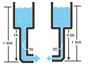
The electrical resistance of a resistor is measured in ohms. The symbol for an ohm is the greek capital-omega: Ω. The (somewhat roundabout) definition of 1Ω is the resistance between two points where 1 volt (1V) of applied potential energy will push 1 ampere (1A) of current.

As SI units go, larger or smaller values of ohms can be matched with a prefix like kilo-, mega-, or giga-, to make large values easier to read. It’s very common to see resistors in the kilohm (kΩ) and megaohm (MΩ) range (much less common to see miliohm (mΩ) resistors). For example, a 4,700Ω resistor is equivalent to a 4.7kΩ resistor, and a 5,600,000Ω resistor can be written as 5,600kΩ or (more commonly as) 5.6MΩ.

Schematic symbol

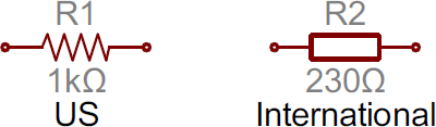
All resistors have two terminals, one connection on each end of the resistor. When modeled on a schematic, a resistor will show up as one of these two symbols:

Resistor schematic symbols

Two common resistor schematic symbols. R1 is an American-style 1kΩ resistor, and R2 is an international-style 47kΩ resistor.

The terminals of the resistor are each of the lines extending from the squiggle (or rectangle). Those are what connect to the rest of the circuit.

The resistor circuit symbols are usually enhanced with both a resistance value and a name. The value, displayed in ohms, is obviously critical for both evaluating and actually constructing the circuit. The name of the resistor is usually an R preceding a number. Each resistor in a circuit should have a unique name/number. For example, here’s a few resistors in action on a 555 timer circuit:

Example schematic with resistors - a 555 timer

In this circuit, resistors play a key role in setting the frequency of the 555 timer’s output. Another resistor (R3) limits the current through an LED.

Types of Resistors

Resistors come in a variety of shapes and sizes. They might be through-hole or surface-mount. They might be a standard, static resistor, a pack of resistors, or a special variable resistor.

Termination and mounting

Resistors will come in one of two termination-types: through-hole or surface-mount. These types of resistors are usually abbreviated as either PTH (plated through-hole) or SMD/SMT (surface-mount technology or device).

Through-hole resistors come with long, pliable leads which can be stuck into a breadboard or hand-soldered into a prototyping board or printed circuit board (PCB). These resistors are usually more useful in breadboarding, prototyping, or in any case where you’d rather not solder tiny, little 0.6mm-long SMD resistors. The long leads usually require trimming, and these resistors are bound to take up much more space than their surface-mount counterparts.

The most common through-hole resistors come in an axial package. The size of an axial resistor is relative to its power rating. A common ½W resistor measures about 9.2mm across, while a smaller ¼W resistor is about 6.3mm long.

1/4 and 1/2 watt resistors

A half-watt (½W) resistor (above) sized up to a quarter-watt (¼W).

Surface-mount resistors are usually tiny black rectangles, terminated on either side with even smaller, shiny, silver, conductive edges. These resistors are intended to sit on top of PCBs, where they’re soldered onto mating landing pads. Because these resistors are so small, they’re usually set into place by a robot, and sent through an oven where solder melts and holds them in place.

SMD resistor on a quarter

A tiny 0603 330Ω resistor hovering over shiny George Washington’s nose on top of a U.S. quarter.

SMD resistors come in standardized sizes; usually either 0805 (0.8mm long by 0.5mm wide), 0603, or 0402. They’re great for mass circuit-board-production, or in designs where space is a precious commodity. They take a steady, precise hand to manually solder, though!

Resistor composition

Resistors can be constructed out of a variety of materials. Most common, modern resistors are made out of either a carbon, metal, or metal-oxide film. In these resistors, a thin film of conductive (though still resistive) material is wrapped in a helix around and covered by an insulating material. Most of the standard, no-frills, through-hole resistors will come in a carbon-film or metal-film composition.

Peeled away view of carbon-film resistors

Peek inside the guts of a few carbon-film resistors. Resistance values from top to bottom: 27Ω, 330Ω and a 3.3MΩ. Inside the resistor, a carbon film is wrapped around an insulator. More wraps means a higher resistance. Pretty neat!

Other through-hole resistors might be wirewound or made of super-thin metallic foil. These resistors are usually more expensive, higher-end components specifically chosen for their unique characteristics like a higher power-rating, or maximum temperature range.

Surface-mount resistors are usually either thick or thin-film variety. Thick-film is usually cheaper but less precise than thin. In both resistor types, a small film of resistive metal alloy is sandwiched between a ceramic base and glass/epoxy coating, and then connected to the terminating conductive edges.

Special resistor packages

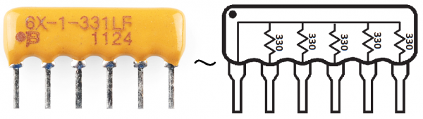
There are a variety of other, special-purpose resistors out there. Resistors may come in pre-wired packs of five-or-so resistor arrays. Resistors in these arrays may share a common pin, or be set up as voltage dividers.

Resistor Network

An array of five 330Ω resistors, all tied together at one end.

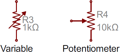
Resistors don’t have to be static either. Variable resistors, known as rheostats, are resistors which can be adjusted between a specific range of values. Similar to the rheostat is the potentiometer. Pots connect two resistors internally, in series, and adjust a center tap between them creating an adjustable voltage divider. These variable resistors are often used for inputs, like volume knobs, which need to be adjustable.

A smattering of potentiometers

A smattering of potentiometers. From top-left, clockwise: a standard 10k trimpot, 2-axis joystick, softpot, slide pot, classic right-angle, and a breadboard friendly 10k trimpot.

Decoding Resistor Markings

Though they may not display their value outright, most resistors are marked to show what their resistance is. PTH resistors use a color-coding system (which really adds some flair to circuits), and SMD resistors have their own value-marking system.

Decoding the color bands

Through-hole, axial resistors usually use the color-band system to display their value. Most of these resistors will have four bands of color circling the resistor.

Resistors showing their stripes

The first two bands indicate the two most-significant digits of the resistor’s value. The third band is a weight value, which multiplies the two significant digits by a power of ten.

The final band indicates the tolerance of the resistor. The tolerance explains how much more or less the actual resistance of the resistor can be compared to what its nominal value is. No resistor is made to perfection, and different manufacturing processes will result in better or worse tolerances. For example, a 1kΩ resistor with 5% tolerance could actually be anywhere between 0.95kΩ and 1.05kΩ.

How do you tell which band is first and last? The last, tolerance band is often clearly separated from the value bands, and usually it’ll either be silver or gold.

Here’s a table of each of the colors and which value, multiplier or tolerance they represent:

ColorDigit valueMultiplierMultiplied OutTolerance
Black01001
Brown110110
Red2102100
Orange31031,000
Yellow410410000
Green5105100,000
Blue61061,000,000
Violet710710,000,000
Gray8108100,000,000
White91091,000,000,000
Gold±5%
Silver±10%

Here’s an example of a 4.7kΩ resistor with four color bands:

Close-up of a 4.7kOhm resistor

When decoding the resistor color bands, consult a resistor color code table like the one above. For the first two bands, find that color’s corresponding digit value. The 4.7kΩ resistor has color bands of yellow and violet to begin – which have digit values of 4 and 7 (47). The third band of the 4.7kΩ is red, which indicates that the 47 should be multiplied by 102 (or 100). 47 times 100 is 4,700!

If you’re trying to commit the color band code to memory, a mnemonic device might help. There are a handful of (sometimes unsavory) mnemonics out there, to help remember the resistor color code. A good one, which spells out the difference between black and brown is:

"Big brown rabbits often yield great big vocal groans when gingerly snapped."

Or, if you remember “ROY G. BIV”, subtract the indigo (poor indigo, no one remembers indigo), and add black and brown to the front and gray and white to the back of the classic rainbow color-order.

Color Code Calculator

If you’d rather skip the math (we won’t judge :), and just use a handy calculator, give this a try!

Band 1Band 2Band 3Band 4
Value 1 (MSV)Value 2WeightTolerance
   

Resistance:  

1,000 Ω ±5%

Decoding surface-mount markings

SMD resistors, like those in 0603 or 0805 packages, have their own way of displaying their value. There are a few common marking methods you’ll see on these resistors. They’ll usually have three to four characters — numbers or letters — printed on top of the case.

If the three characters you’re seeing are all numbers, you’re probably looking at an E24 marked resistor. These markings actually share some similarity with the color-band system used on the PTH resistors. The first two numbers represent the first two most-significant digits of the value, the last number represents a magnitude.

Examples of E-24 marked SMD resistors

In the above example picture, resistors are marked 104, 105, 205, 751, and 754. The resistor marked with 104 should be 100kΩ (10x104), 105 would be 1MΩ (10x105), and 205 is 20MΩ (20x105). 751 is 750Ω (75x101), and 754 is 750kΩ (75x104).

Another common coding system is E96, and it’s the most cryptic of the bunch. E96 resistors will be marked with three characters — two numbers at the beginning and a letter at the end. The two numbers tell you the first three digits of the value, by corresponding to one of the not-so-obvious values on this lookup table.

CodeValue
CodeValue
CodeValue
CodeValue
CodeValue
CodeValue
01100
17147
33215
49316
65464
81681
02102
18150
34221
50324
66475
82698
03105
19154
35226
51332
67487
83715
04107
20158
36232
52340
68499
84732
05110
21162
37237
53348
69511
85750
06113
22165
38243
54357
70523
86768
07115
23169
39249
55365
71536
87787
08118
24174
40255
56374
72549
88806
09121
25178
41261
57383
73562
89825
10124
26182
42267
58392
74576
90845
11127
27187
43274
59402
75590
91866
12130
28191
44280
60412
76604
92887
13133
29196
45287
61422
77619
93909
14137
30200
46294
62432
78634
94931
15140
31205
47301
63442
79649
95953
16143
32210
48309
64453
80665
96976

The letter at the end represents a multiplier, matching up to something on this table:

LetterMultiplierLetterMultiplierLetterMultiplier
Z0.001A1D1000
Y or R0.01B or H10E10000
X or S0.1C100F100000

Resistors marked with E-96 codes

So a 01C resistor is our good friend, 10kΩ (100x100), 01B is 1kΩ (100x10), and 01D is 100kΩ. Those are easy, other codes may not be. 85A from the picture above is 750Ω (750x1) and 30C is actually 20kΩ.

Power Rating

The power rating of a resistor is one of the more hidden values. Nevertheless it can be important, and it’s a topic that’ll come up when selecting a resistor type.

Power is the rate at which energy is transformed into something else. It’s calculated by multiplying the voltage difference across two points by the current running between them, and is measured in units of a watt (W). Light bulbs, for example, power electricity into light. But a resistor can only turn electrical energy running through it into heat. Heat isn’t usually a nice playmate with electronics; too much heat leads to smoke, sparks, and fire!

Every resistor has a specific maximum power rating. In order to keep the resistor from heating up too much, it’s important to make sure the power across a resistor is kept under it’s maximum rating. The power rating of a resistor is measured in watts, and it’s usually somewhere between ⅛W (0.125W) and 1W. Resistors with power ratings of more than 1W are usually referred to as power resistors, and are used specifically for their power dissipating abilities.

Finding a resistor’s power rating

A resistor’s power rating can usually be deduced by observing its package size. Standard through-hole resistors usually come with ¼W or ½W ratings. More special purpose, power resistors might actually list their power rating on the resistor.

Some examples of power resistors

These power resistors can handle a lot more power before they blow. From top-right to bottom-left there are examples of 25W, 5W and 3W resistors, with values of 2Ω, 3Ω 0.1Ω and 22kΩ. Smaller power-resistors are often used to sense current.

The power ratings of surface mount resistors can usually be judged by their size as well. Both 0402 and 0603-size resistors are usually rated for 1/16W, and 0805’s can take 1/10W.

Measuring power across a resistor

Power is usually calculated by multiplying voltage and current (P = IV). But, by applying Ohm’s law, we can also use the resistance value in calculating power. If we know the current running through a resistor, we can calculate the power as:

P=I^2*R

Or, if we know the voltage across a resistor, the power can be calculated as:

P=V^2/R

Series and Parallel Resistors

Resistors are paired together all the time in electronics, usually in either a series or parallel circuit. When resistors are combined in series or parallel, they create a total resistance, which can be calculated using one of two equations. Knowing how resistor values combine comes in handy if you need to create a specific resistor value.

Series resistors

When connected in series resistor values simply add up.

Schematic of resistors in series

Equation for adding resistors in series

N resistors in series. The total resistance is the sum of all series resistors.

So, for example, if you just have to have a 12.33kΩ resistor, seek out some of the more common resistor values of 12kΩ and 330kΩ, and butt them up together in series.

Parallel resistors

Finding the resistance of resistors in parallel isn’t quite so easy. The total resistance of N resistors in parallel is the inverse of the sum of all inverse resistances. This equation might make more sense than that last sentence:

Schematic of resistors in parallel

Equation for adding resistors in parallel

N resistors in parallel. To find the total resistance, invert each resistance value, add them up, and then invert that.

(The inverse of resistance is actually called conductance, so put more succinctly: the conductance of parallel resistors is the sum of each of their conductances).

As a special case of this equation: if you have just two resistors in parallel, their total resistance can be calculated with this slightly-less-inverted equation:

Equation for calculating two resistors in parallel

As an even more special case of that equation, if you have two parallel resistors of equal value the total resistance is half of their value. For example, if two 10kΩ resistors are in parallel, their total resistance is 5kΩ.

A shorthand way of saying two resistors are in parallel is by using the parallel operator: ||. For example, if R1 is in parallel with R2, the conceptual equation could be written as R1||R2. Much cleaner, and hides all those nasty fractions!

Resistor networks

As a special introduction to calculating total resistances, electronics teachers just love to subject their students to finding that of crazy, convoluted resistor networks.

A tame resistor network question might be something like: “what’s the resistance from terminals A to B in this circuit?”

An example of a resistor network

To solve such a problem, start at the back-end of the circuit and simplify towards the two terminals. In this case R7, R8 and R9 are all in series and can be added together. Those three resistors are in parallel with R6, so those four resistors could be turned into one with a resistance of R6||(R7+R8+R9). Making our circuit:

Resistor network simplified

Now the four right-most resistors can be simplified even further. R4, R5 and our conglomeration of R6– R9 are all in series and can be added. Then those series resistors are all in parallel with R3.

Resistor network further simplified

And that’s just three series resistors between the A and B terminals. Add ‘em on up! So the total resistance of that circuit is: R1+R2+R3||(R4+R5+R6||(R7+R8+R9)).

Example Applications

Resistors exist in just about every electronic circuit ever. Here are a few examples of circuits, which heavily depend on our resistor friends.

LED Current Limiting

Resistors are key in making sure LEDs don’t blow up when power is applied. By connecting a resistor in series with an LED, current flowing through the two components can be limited to a safe value.

Current limiting resistor schematic

When sizing out a current-limiting resistor, look for two characteristic values of the LED: the typical forward voltage, and the maximum forward current. The typical forward voltage is the voltage which is required to make an LED light up, and it varies (usually somewhere between 1.7V and 3.4V) depending upon the color of the LED. The maximum forward current is usually around 20mA for basic LEDs; continuous current through the LED should always be equal to or less than that current rating.

Once you’ve gotten ahold of those two values, you can size up a current-limiting resistor with this equation:

Current limiting resistor = (Vs-Vf)/If

VS is the source voltage — usually a battery or power supply voltage. VF and IF are the LED’s forward voltage and the desired current that runs through it.

For example, assume you have a 9V battery to power an LED. If your LED is red, it might have a forward voltage around 1.8V. If you want to limit the current to 10mA, use a series resistor of about 720Ω.

Current limiting example equation R=(9-1.8)/.010

Voltage Dividers

A voltage divider is a resistor circuit which turns a large voltage into a smaller one. Using just two resistors in series, an output voltage can be created that’s a fraction of the input voltage.

Here’s the voltage divider circuit:

Voltage divider circuit

Two resistors, R1 and R2, are connected in series and a voltage source (Vin) is connected across them. The voltage from Vout to GND can be calculated as:

Voltage divider equation

For example, if R1 was 1.7kΩ and R2 was 3.3kΩ, a 5V input voltage could be turned into 3.3V at the Vout terminal.

Voltage dividers are very handy for reading resistive sensors, like photocells, flex sensors, and force-sensitive resistors. One half of the voltage divider is the sensor, and the part is a static resistor. The output voltage between the two components is connected to an analog-to-digital converter on a microcontroller (MCU) to read the sensor’s value.

A photocell and resistor make a light sensor

Here a resistor R1 and a photocell create a voltage divider to create a variable voltage output.
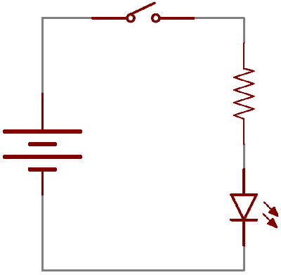
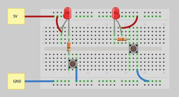
Pull-up Resistors

A pull-up resistor is used when you need to bias a microcontroller’s input pin to a known state. One end of the resistor is connected to the MCU’s pin, and the other end is connected to a high voltage (usually 5V or 3.3V).

Without a pull-up resistor, inputs on the MCU could be left floating. There’s no guarantee that a floating pin is either high (5V) or low (0V).

Pull-up resistors are often used when interfacing with a button or switch input. The pull-up resistor can bias the input-pin when the switch is open. And it will protect the circuit from a short when the switch is closed.

A resistor pulling up a button input

In the circuit above, when the switch is open the MCU’s input pin is connected through the resistor to 5V. When the switch closes, the input pin is connected directly to GND.

The value of a pull-up resistor doesn’t usually need to be anything specific. But it should be high enough that not too much power is lost if 5V or so is applied across it. Usually values around 10kΩ work well.

Going Futher

Now that you’re a budding expert on all things resistor, how ‘bout exploring some more fundamental electronics concepts! Resistors certainly aren’t the only basic component we use in electronics, there’s also:

Or maybe you’d like to further explore resistor applications?


learn.sparkfun.com |CC BY-SA 3.0 | SparkFun Electronics | Boulder, Colorado


Accelerometer Basics

$
0
0

Accelerometer Basics a learn.sparkfun.com tutorial

What is an Accelerometer?

Accelerometers are devices that measure acceleration, which is the rate of change of the velocity of an object. They measure in meters per second squared (m/s2) or in G-forces (g). A single G-force for us here on planet Earth is equivalent to 9.8 m/s2, but this does vary slightly with elevation (and will be a different value on different planets due to variations in gravitational pull). Accelerometers are useful for sensing vibrations in systems or for orientation applications.

Accelerometer breakout board

ADXL345 Breakout Board

Concepts in This Tutorial

If you are unfamiliar with any of the topics below, you may want to read up on those before moving ahead with accelerometers.

How an Accelerometer Works

Accelerometers are electromechanical devices that sense either static or dynamic forces of acceleration. Static forces include gravity, while dynamic forces can include vibrations and movement.

Accelerometer axes of measurement

Axes of measurement for a triple axis accelerometer

Accelerometers can measure one, two, or three axes of rotation. 3-axis units are becoming more common as the cost of development for them decreases.

Generally, accelerometers contain capacitive plates internally. Some of these are fixed, while others are attached to miniscule springs that move internally as acceleration forces act upon the sensor. As these plates move in relation to each other, the capacitance between them changes. From these changes in capacitance, the acceleration can be determined.

Other accelerometers can be centered around piezoelectric materials. These tiny crystal structures output electrical charge when placed under mechanical stress ( e.g. acceleration).

alt text

An example of the inside of a piezoelectric accelerometer

How to Connect to an Accelerometer

For most accelerometers, the basic connections required for operation are power and the communication lines. As always, read the datasheet to ensure proper connections are made.

Communication Interface

Accelerometers will communicate over an analog, digital, or pulse-width modulated connection interface.

  • Accelerometers with an analog interface show accelerations through varying voltage levels. These values generally fluctuate between ground and the supply voltage level. An ADC on a microcontroller can then be used to read this value. These are generally less expensive than digital accelerometers.

  • Accelerometers with a digital interface can either communicate over SPI or I2C communication protocols. These tend to have more functionality and be less susceptible to noise than analog accelerometers.

  • Accelerometers that output data over pulse-width modulation (PWM) output square waves with a known period, but a duty cycle that varies with changes in acceleration.

Power

Accelerometers are generally low-power devices. The required current typically falls in the micro (µ) or milli-amp range, with a supply voltage of 5V or less. The current consumption can vary depending on the settings (e.g., power saving mode versus standard operating mode). These different modes can make accelerometers well suited for battery powered applications.

Make sure that proper logic levels are matched, especially with the digital interfaces.

How to Select an Accelerometer

When choosing which accelerometer to use, several features are important to consider including power requirements and communication interfaces as discussed previously. Additional features for consideration are below.

Range

Most accelerometers will have a selectable range of forces they can measure. These ranges can vary from ±1g up to ±250g. Typically, the smaller the range, the more sensitive the readings will be from the accelerometer. For example, to measure small vibrations on a tabletop, using a small-range accelerometer will provide more detailed data than using a 250g range (which is more suited for rockets).

ADXL362

The ADXL362 Triple Axis Accelerometer can measure ±2g, ±4g, and ±8g.

Additional Features

Some accelerometers include features such as tap detection (useful for low-power applications), free-fall detection (used for Active Hard Drive Protection), temperature compensation (to increase accuracy in dead reckoning situations ) and 0-g range sensing, which are other features to take into consideration when purchasing an accelerometer. The need for these types of features on the accelerometer will be determined by the application in which the accelerometer is incorporated.

There are also IMUs (Inertial Measurement Units) available, which can include accelerometers, gyroscopes and even, occasionally, magnetometers into a single IC package or board. Some examples of this include the MPU6050 and MPU9150. These are commonly used in motion tracking applications and UAV guidance systems, where location and orientation of an object is important.

Going Further

You should now have all the basic tools and skills required to implement an accelerometer in your own project.

Please check out the following links, to learn more about accelerometers:


learn.sparkfun.com |CC BY-SA 3.0 | SparkFun Electronics | Boulder, Colorado

Switch Basics

$
0
0

Switch Basics a learn.sparkfun.com tutorial

Introduction

One of the most elementary and easy-to-overlook circuit component is the switch. They don’t require any fancy equations to evaluate. All they do is select between an open circuit and a short circuit. Simple. But how could we live without buttons and switches!? What good is a blinky circuit with no user input? Or a deadly robot with no kill switch? What would our world be without with big red buttons you should never, ever press.

In this tutorial we’ll cover all things buttons and switches. Stuff like:

  • Momentary vs. Maintained Switches
  • What do SPST, SPDT, DPDT, etc. all mean?
  • The difference between normally closed and normally open buttons
  • Lots of pretty button pictures
  • Important switch ratings
  • Switch applications

Consider Reading

Before diving into this tutorial, make sure you’re up to snuff on the most basic of electronics knowledge. If you’re not familiar with the following concepts, consider reading their tutorials first. Then come back, and we’ll have some fun button talk.

What is a Switch?

A switch is a component which controls the open-ness or closed-ness of an electric circuit. They allow control over current flow in a circuit (without having to actually get in there and manually cut or splice the wires). Switches are critical components in any circuit which requires user interaction or control.

A switch can only exist in one of two states: open or closed. In the off state, a switch looks like an open gap in the circuit. This, in effect, looks like an open circuit, preventing current from flowing.

In the on state, a switch acts just like a piece of perfectly-conducting wire. A short. This closes the circuit, turning the system “on” and allowing current to flow unimpeded through the rest of the system.

alt text

A circuit diagram with an LED, resistor, and a switch. When the switch is closed, current flows and the LED can illuminate. Otherwise no current flows, and the LED receives no power.

There are tons and tons of switches out there: toggle, rotary, DIP, push-button, rocker, membrane, … the list just goes on and on. Each of those switch types has a set of unique characteristics to differentiate it from others. Characteristics like what action flips the switch, or how many circuits the switch can control. Next up, we’ll go over some of the more basic switch characteristics.

Defining Characteristics

Actuation Method

In order to change from one state to another, a switch must be actuated. That is, some sort of physical action must be performed to “flip” the switch’s state. The actuation-method of a switch is one of its more defining characteristics.

Switch actuation examples

Some examples of switch types. Push button, rocker, slide, and magnetic.

Switch actuation can come from pushing, sliding, rocking, rotating, throwing, pulling, key-turning, heating, magnetizing, kicking, snapping, licking,…any physical interaction which can cause the mechanical linkages inside the switch to come into, or go out of, contact.

Momentary vs. Maintained

All switches fall into one of two distinct categories: momentary or maintained.

Maintained switches — like the light switches on your wall — stay in one state until actuated into a new one, and then remain in that state until acted upon once again. These switches might also be called toggle or ON/OFF switches.

Momentary switches only remain active as long as they’re actuated. If they’re not being actuated, they remain in their “off” state. You’ve probably got a momentary switch (or 50) right in front of you…keys on a keyboard!

Semantic alert! Most of the switches we refer to as “buttons” fall in the momentary category. Activating a button usually means pressing down on it in some manner, which just feels like a momentary control. There are such things as a maintained button, but for this tutorial when we slip and talk about “buttons”, think “momentary push-down switch”.

Mounting Style

As with most components, the termination style of a switch always comes down to either surface mount (SMD) or through-hole (PTH). Through-hole switches are usually larger in size. Some might be designed to fit in a breadboard for easy prototyping.

Buttons in a breadboard

These Tactile buttons are through-hole and fit perfectly in a breadboard. Great for prototyping!

SMD switches are smaller than their PTH counterparts. They sit flat, on top of a PCB. SMD switches usually require a gentle touch, they’re not built to sustain as much switching force as a through-hole switch.

SMD buttons on an Arduino Pro

The Arduino Pro has two SMD switches: a slide switch for power control, and a push-button for reset control.

Panel mount switches — designed to sit outside an enclosure — are a popular mounting style as well. It’s hard to flip a switch when it’s hidden inside an enclosure. Panel mount switches come in all sorts of termination styles: PTH, SMD, or heavy-duty solder lugs for soldering to wires.

Panel mounted toggle switch

A panel mounted illuminated toggle switch.


One more important switch characteristic, which really deserves a page of its own, is the internal circuit arrangement of a switch. Are you looking for an SPST? DPST? 4PDT? What-P-what-now?

Poles and Throws, Open and Closed

A switch must have at least two terminals, one for the current to (potentially) go in, another to (potentially) come out. That only describes the simplest version of a switch though. More often than not, a switch has more than two pins. So how do all of those terminals line up with the internal workings of the switch? This is where knowing how many poles and throws a switch has is essential.

The number of poles* on a switch defines how many separate circuits the switch can control. So a switch with one pole, can only influence one single circuit. A four-pole switch can separately control four different circuits.

A switch’s throw-count defines how many positions each of the switch’s poles can be connected to. For example, if a switch has two throws, each circuit (pole) in the switch can be connected to one of two terminals.

Knowing how many poles and throws a switch has, it can be more specifically classified. Commonly you’ll see switches defined as “single-pole, single-throw”, “single-pole, double-throw”, “double-pole, double-throw”, which are more often abbreviated down to SPST, SPDT, and DPDT, respectively.

SPST

A single-pole, single-throw (SPST) switch is as simple as it gets. It’s got one output and one input. The switch will either be closed or completely disconnected. SPSTs are perfect for on-off switching. They’re also a very common form of momentary switches. SPST switches should only require two terminals.

SPST circuit example and real-life example

The circuit symbol for an SPST switch in the off position and a through-hole, right-angle, maintained, SPST, rocker switch.

SPDT

Another common switch-type is the SPDT. SPDTs have three terminals: one common pin and two pins which vie for connection to the common. SPDTs are great for selecting between two power sources, swapping inputs, or whatever it is you do with two circuits trying to go one place. Most simple slide switches are of the SPDT variety. SPDT switches should usually have three terminals. (Sidenote: in a pinch an SPDT can actually be made into an SPST by just leaving one of the switch throws unconnected).

An SPDT circuit example and real-life example

An SPDT switch circuit symbol, and an SPDT slide switch.

DPDT

Adding another pole to the SPDT creates a double-pole, double-throw (DPDT) switch. Basically two SPDT switches, which can control two separate circuits, but are always switched together by a single actuator. DPDTs should have six terminals.

DPDT examples

A DPDT circuit symbol, and a 6-terminal DPDT rocker switch.

XPYT

Switches with more than two poles or throws are not too common, but they’re out there (in all their oddly-shaped, difficult-to-connect-to glory). Once we get past one or two poles/throws, we just start sticking numbers in the abbreviation. Here’s a 4PDT switch, for example, it can control four separate circuits, 2 positions per circuit:

A 4PDT switch

A massive 4PDT circuit symbol, and an physically massive 4PDT toggle switch.


* Just remember: it’s “poles”, not “pulls”. Seasoned engineers just love picking on poor saps who were only looking for a “single-pull, double-throw” switch. (Not speaking from experience here or anything… I mean, in my defence, I didn’t read it in a book, just heard it ambiguously pronounced by the professor. Meanies.)

Normally Open/Closed

When a momentary switch is not actuated, it’s in a “normal” state. Depending on how the button is constructed, its normal state can be either an open circuit or a short circuit. When a button is open until actuated, it’s said to be normally open (abbreviated NO). When you actuate an NO switch, you’re closing the circuit, which is why these are also called “push-to-make” switches.

Conversely, if a button usually acts like a short circuit unless actuated, it’s called a normally closed (NC) switch. NC switches are “push-to-break”; actuating the switch creates an open circuit.

Among the two types, you’re probably much more likely to encounter a normally open momentary switch.

Momentary Switches

Momentary switches are switches which only remain in their on state as long as they’re being actuated (pressed, held, magnetized, etc.). Most often momentary switches are best used for intermittent user-input cases; stuff like reset or keypad buttons.

Examples of Momentary Switches

Push-button

Push-button switches are the classic momentary switch. Typically these switches have a really nice, tactile, “clicky” feedback when you press them. They come in all sorts of flavors: big, small, colorful, illuminated (when an LED shines up through the button). They might be terminated as through-hole, surface-mount, or even panel-mount.

Assortment of tactile switches

An assortment of tactile push-button switches. Starting top-left, clockwise: blue and pink arcade buttons, 12mm push button, white capped button, orange illuminated, right-angle, panel-mount, and a mini push button.

Button Matrices

Large arrays of momentary buttons, like your keyboard or even smaller groupings like a keypad, usually arrange all of their switches into a big matrix. Every button on the pad is assigned a row and column . This requires some extra button-press-processing on the microcontroller end, but free’s up a big chunk of I/O pins.

12-button keypad

Etc.

Momentary switches don’t always have to be actuated by a pushdown. It could be push-sideways, like the movement action in a handful of joysticks.

Joysticks

An arcade joystick uses four microswitches to sense up, down, left and right movements. The tiny little surface-mount 5-way tactile switch is an SP5T directional switch (up, down, left, right, and press-down).

On the other end of the spectrum, reed switches open or close when exposed to the presence of a magnetic field. These are great for making a non-contact switch.

Reed switches

A couple of reed switches: non-insulated (bottom) and insulated.

Maintained Switches

A maintained switch retains its state until it’s actuated into a new one. Just look to the nearest wall for an example of a maintained switch — the thing controlling your lights! Maintained switches are great for set-it-and-leave it applications like turning power on and off.

Examples of Maintained Switches

Slide Switch

Need a really basic, no-frills ON/OFF or selector switch. Slide switches might be for you! These switches have a tiny little nub which protrudes from the switch, and it slides across the body into one of two (or more) positions.

You’ll usually find slide switches in SPDT or DPDT configurations. The common terminal is usually in the middle, and the two select positions are on the outside.

Examples of slide switches

Some examples of slide switches: a mini PTH slide switch, an SMD right-angle switch, and an SMD DPDT slide switch mounted on a LilyPad.

Toggle Switch

When you hear toggle switch, think “fire ze missiles!”. Toggle switches have a long lever, which moves in a rocking motion. As they move to a new position, toggle switches make a really satisfying “snap”.

Toggle switch covered

Missle-launch covers are a must when using toggle switches.

Toggle switches are commonly SPST (two terminals) or SPDT (three terminals), though you can find them in otherflavors as well. As usual, you can find them in through-hole, surface-mount, or — probably most commonly — as panel-mountable.

DIP Switch

DIP switches are through-hole switches designed in the same mold as a through-hole DIP IC. They can be placed in a breadboard, in the same manner a through-hole IC might, by straddling the center area.

An 8-position DIP switch

An 8-position DIP switch, handy for configuring 8 somethings.

These switches often come in arrays of eight or more separate SPST switches, with tiny little sliding levers. They were widely used in the olden days of computing, but they’re still useful for configuring a devices via hardware.

Latching Buttons

Push-buttons aren’t all momentary. Some push-buttons will latch into place, maintaining their state until pressed again latching back to where the started. These can be found, for example, in stomp switches on guitar effect pedals.

Latching button

Etc.

We’ve barely started to cover the huge variety of maintained switches out there. There’s pull-chain switches, which add a really classy touch to your project. Key-switches, for when you don’t want just anybody turning on your killer robot. Rotary switches— like those on a multimeter — provide a unique input device, especially when you’ve need a high number of throws.

Assorted maintained switches

And, of course, what mad scientist could live without a big ol’ knife-switch?

Switch Applications

On/Off Control

Among the most obvious of switch applications is simple on and off control. The type of control you perform every time you walk into a dark room. An on/off switch can be implemented by simply sticking an SPST switch in series with a power-line. Usually the on/off switch will be maintained, like a toggle or slide switch, but momentary on/off switches can have their purpose.

Example on/off circuit

On this Breadboard Power Supply, an SPDT switch is used to turn the circuit on and off. (A second SPDT switch is used to select the adjustable voltage regulator’s output value by adjusting a voltage divider.)

When implementing such a switch, keep in mind that all the current your project consumes is going to run through that switch. Ideally a switch is a perfect conductor, but realistically it’s got a small amount of resistance between the two contacts. Because of that resistance, all switches are rated for a maximum amount of current they can withstand. Exceed a switch’s maximum current rating, and you can expect melted plastic and magic smoke.

For example, this SPDT slide switch is great for controlling current flow in small projects (like Simons or Metronomes), but don’t try using it to control beefy motor controllers, or strings of 100 LEDs. For that, consider using something like a 4A toggle switch or a 6A lamp switch.

User Input

Of course, user input is one of the more common applications for switches. For example, if you want to connect a switch to a microcontroller input pin, a simple circuit like this is all you’d need:

Switch into MCU and a pull-up resistor

When the switch is open, the MCU pin is connected through the resistor to 5V. When the switch is closed, the pin is tied directly to GND. The resistor in that circuit is a pull-up resistor, required to bias the input high, and prevent a short to ground when the switch is closed.

Going Further

Well, that about covers the basics of switches. Next up, you could explore some of these other conceptual tutorials:

  • Pull-up Resistors– Pull-up resistors complement most momentary button circuits. They ensure that power and ground don’t short, and they make sure I/O lines don’t float.
  • Transistors– These can be used (among many other things) as sort-of electronically controlled switches.
  • Relays– Another electronically controlled switch. Great for turning on and off high-power circuits.
  • Accelerometer Basics– Motion-sensing accelerometers — like those in most smartphones and new video game controllers — are fast-replacing these boring switches as human input devices.
  • How to Power a Project– What kind of power source will your switch be turning on and off?

Or check out some of our project tutorials for some inspiration for your own projects. Switches are so widely used, we could probably link all of our projects. But here are a couple which make really ingenious use of switches to do their thing:

  • MP3 Player Shield Music Box– This project (bigger on the inside) uses one of those non-traditional switches — a reed switch — to trigger it’s action.
  • The Uncertain 7-Cube– Well, this project doesn’t actually have any switches, but that’s what makes it so special! This project is a great example of how an accelerometer could replace a switch as an input device.

learn.sparkfun.com |CC BY-SA 3.0 | SparkFun Electronics | Boulder, Colorado

Getting Started with the LilyPad MP3 Player

$
0
0

Getting Started with the LilyPad MP3 Player a learn.sparkfun.com tutorial

Introduction

In this tutorial, we are going to go through all the ins and outs of the LilyPad MP3 Player.

The LilyPad MP3 Player is an amazing little board that contains almost everything you need to play audio files. You just need to add a Lipo battery, speakers, and a micro-SD card with your audio files on it.

You can use the LilyPad MP3 Player to create all kinds of noisy projects; your imagination is the only limit!

alt text

Before diving in, you should familiarize yourself with any of the following topics that will be covered in this tutorial, if you are not comfortable with them already.

Getting to Know the LilyPad MP3 Player

LilyPad MP3 Player

The LilyPad MP3 Player comes with preinstalled software called “Trigger” that will play specific files when the input pins are grounded. You can also add an optional rotary encoder and load the “Player” software to turn the board into a “real” audio player, or even write your own software using the free Arduino programming environment.

Anatomy of the LilyPad MP3 Player:

LilyPad MP3 Player connectors

Let’s start with the connectors. You will normally power the board with a single-cell (3.7V) Lipo battery, which plugs into the two-pin “JST” battery connector. There is a stereo headphone jack that you can use to connect the board to a pair of headphones if desired. Connecting headphones will disable the speakers, but you can change this behavior if you wish. (If you’d like to connect the board to an external amplifier, see the special note here.) You can plug a 5V FTDI board or cable into the 6-pin 5V FTDI header, to both recharge an attached Lipo battery and to reprogram the board if desired (see this note about powering the board from USB). And finally, there is a micro-SD card socket into which you’ll insert a micro-SD memory card containing the audio files you want to play.

LilyPad MP3 Player power switch and LEDs

The board contains a power switch that is used to turn the board on and off. There are also two LEDs; a red power LED that will light up when the board is powered on, and a yellow charge LED. The charge LED will light up when the battery is being charged, and go out when it is full. (It is also normal for the charge LED to turn on if no battery is attached.) You can charge the battery while the board is on or off, but the battery will charge faster if the board is off.

LilyPad MP3 Player I/O pins

The LilyPad MP3 Player has twelve “pins” (they’re really holes, but they connect to pins on the microcontroller) that you’ll use to connect to the outside world. For each pin, we’ve provided both “sew taps” (large holes you can loop conductive thread around to use it in fabric projects), and standard headers (smaller holes that you can solder wires or header pins to if you wish).

Five of the pins are set up to be triggers, which you can use with the default software to trigger playback of specific audio files. (We’ll learn more about this on the next page, “Using the default trigger sketch”.) Typically you’ll connect triggers to switches that activate the playback of various audio files. Many of the triggers also have alternate functions, such as serial ports, that you can use to communicate with other devices in more complex projects. The alternate functions are listed in the table below.

You’ll also use the pins to connect to external speakers. The LilyPad MP3 Player includes a stereo (two channel, left and right) amplifier that supports speakers between 4 and 8 ohms. Each speaker has two terminals, labeled “+” and “–”. Normally you’ll connect two speakers to the board, but you can also use just one speaker if you wish, or connect multiple speakers in series or parallel. Just don’t connect the speaker pins to anything but a speaker or transducer.

Here is a table of the pins and their functions:

pin namefunctionnotes
VINRaw voltage in (3.5V to 6V)If you don't want to connect a Lipo battery, you can use this pin to power the board from an external supply. If you want to also charge an attached Lipo battery, this input should be between 4.5V and 6V. You can read more about your options for powering the board here.
3.3VRegulated 3.3V in or outIf you already have a regulated 3.3V supply, you can use this pin to power the board. (Powering the board through this pin will not charge the battery.) You can also pull 3.3V power out of this pin if you need it somewhere else.
GNDGround (0V)Use as a power ground, and also for the return side of your trigger switches (see the diagram here).
T1Trigger 1General purpose I/O pin (Arduino pin A0). You'll usually connect this through a switch to ground. Can also be used as an analog input.
T2Trigger 2 / SDAGeneral purpose I/O pin (Arduino pin A4). You'll usually connect this through a switch to ground. Can also be used as SDA (serial data) in an I2C ("wire" library) connection (4.7K pullup included), or an analog input if the pullup is disabled.
T3Trigger 3 / SCLGeneral purpose I/O pin (Arduino pin A5). You'll usually connect this through a switch to ground. Can also be used as SCL (serial clock) in an I2C ("wire" library) connection (4.7K pullup included), or an analog input if the pullup is disabled.
T4Trigger 4 / TXGeneral purpose I/O pin (Arduino pin D1). You'll usually connect this through a switch to ground. Can also be used as TX (transmit) in a serial connection. Do not permanently pull this pin low or reprogramming and serial monitoring will be disabled.
T5Trigger 5 / RXGeneral purpose I/O pin (Arduino pin D0). You'll usually connect this through a switch to ground. Can also be used as RX (receive) in a serial connection. Do not permanently pull this pin low or reprogramming and serial monitoring will be disabled.
Right Speaker +Right Speaker +Connect to the right speaker + terminal. Only connect to a speaker or other coil-based transducer. Do not short to power, ground, or any other signal.
Right Speaker -Right Speaker -Connect to the right speaker - terminal. Only connect to a speaker or other coil-based transducer. Do not short to power, ground, or any other signal.
Left Speaker +Left Speaker +Connect to the left speaker + terminal. Only connect to a speaker or other coil-based transducer. Do not short to power, ground, or any other signal.
Left Speaker -Left Speaker -Connect to the left speaker - terminal. Only connect to a speaker or other coil-based transducer. Do not short to power, ground, or any other signal.

You may have noticed the unused footprint in the middle of the board. That is there to allow you to add an optional RGB rotary encoder if you wish. You won’t need it to run the preinstalled “Trigger” software, but if you want to turn the LilyPad MP3 Player into a true audio player, the rotary encoder provides a simple user interface to switch tracks and change the volume. See the “Getting started with the player sketch” page for more information.

LilyPad MP3 Player hardware

In case you’re interested in the hardware on the board, there is an ATmega 328p microprocessor, running Arduino software that pulls data from audio files on the micro-SD card and feeds that data to the VS1053B audio-decoding chip. The VS1053B transforms the digital audio data back into analog audio signals. The audio signals are sent to the headphone jack and a TPA2016D2 stereo amplifier, which boosts the audio signal for the speakers. We also threw in a MCP73831 Lipo battery charger to make it easy to recharge the battery from the FTDI port. Neat, huh?

Tips on speaker selection

The TPA2016D2 stereo amplifier on the LilyPad MP3 Player is capable of driving about a watt of power into each channel. This doesn’t sound like much, but it can produce surprising volume from a large speaker.

In general, larger speakers will sound better than small ones, so use the largest ones that your project will accommodate. Don’t worry that the speaker is marked “20 watts” or higher; that is just the maximum power that the speaker is designed to handle. We’ve had great results with recycled automotive and PC speakers, and even large cabinet speakers.

If your project requires a small speaker, remember that any small speaker will sound much better if it has an enclosed cavity behind it. You can do this with a project enclosure, recycled food containers, etc. Use your imagination!

Some important things to know:

  • Always turn the LilyPad MP3 Player off before inserting or removing the micro-SD card. This will prevent corruption of the data on the card.

  • The 5V FTDI port is provided to charge an attached Lipo battery, and provide a way to reprogram the board. It will power the board if no audio is playing, but will not provide enough power to drive the speakers (the board will reset while playing). In general, the best way to power the LilyPad MP3 Player is with a Lipo battery. If you’d like to use an external supply, see the instructions here, and if you really want to run the board from FTDI power you can hack it to do so.

  • To recharge an attached Lipo battery, plug a 5V FTDI Basic or cable into the 6-pin FTDI connector. Match up the direction of your FTDI board or cable with the “GRN” and “BLK” markings on either side of the connector. The yellow “Charge” light will turn on while the battery is charging and turn off when it’s fully charged. It’s normal for the charge light to turn on if no battery is attached. The charge rate is set to 500mA, which means that a 1000mAh battery will charge in about two hours. If you’d like to change the charge rate, see the instructions here.

  • The LilyPad MP3 Player’s headphone jack is safe for headphones, but don’t connect it to an external amplifier unless you’re using a battery to power the LilyPad. (The fine print is that if the audio ground is shorted to the power ground, the audio decoder chip will be damaged).

  • The VS1053B chip understands a large variety of audio file formats, but we’ll occasionally run into one it can’t play back (it will quietly skip it). See the list of formats and bitrates it understands here. If you do run into a file it has problems with, you can often fix the problem by translating the file into a different format using the audio software of your choice.

  • The LilyPad MP3 Player is washable, but because conductive thread connections can be fragile, we recommend washing your project as little as possible. Please hand-wash, and be sure to remove the Lipo battery and micro-SD card before washing. Because water can get into lots of little crevices, allow everything to air-dry for several days before powering it up again.

With that out of the way, let’s start playing audio!

Getting Started with the Default "Trigger" Sketch

The LilyPad MP3 Player comes with a preinstalled sketch (Arduino programs are called sketches) called “Trigger”. This sketch will wait for one of the five trigger inputs to be grounded and will then play the corresponding audio file from the micro-SD card. You can sew the LilyPad MP3 Player into your project and use “soft switches” to trigger any sound you want. Best of all, since this sketch comes preinstalled on every LilyPad MP3 Player, you can use it right out of the box, with no programming necessary. Let’s get started!

Things you’ll need

Instructions

1. Put up to five audio files onto the micro-SD card. Usually this is done by putting the card into a reader attached to your computer and copying audio files to it. The LilyPad MP3 Player will play a number of audio formats including MP3, WAV, WMA, AAC, MID, etc.

2. Rename the audio files on the micro-SD card so that the first character of each filename is the number “1” to “5”, corresponding to the trigger that you want to play that file. You don’t need to change anything else about the filename.

alt text

3. Turn off the LilyPad MP3 Player and plug your micro-SD card into the socket. Push it in until it clicks; if you release it, it will stay seated. To remove it, push again until it clicks, and it will pop out when you release it.

alt text

4. Connect a headphone to the headphone jack, or connect speakers to the left and right speaker terminals. (Note that when anything is plugged into the headphone jack, the speakers are disabled. This behavior can be changed if desired).

alt text

5. Plug a 3.7V single-cell Lipo battery into the JST connector. Note that a FTDI USB connection will not provide enough power to run the board, so a battery or other external power source is required.

6. Move the power switch to ON. The red LED should light up.

alt text

7. Wait a few seconds for the software to start up. Now, momentarily, connect the ground sew tap (marked GND) to one of the trigger terminals (marked T1 through T5). The audio file associated with that terminal should play through the speakers / headphone. If you don’t hear anything, see the troubleshooting page.

8. To charge the battery or reprogram the board, connect a 5 volt FTDI board to the FTDI header. The yellow LED will light up while the battery is charging, and go out when it’s full. To reprogram the board, see the instructions here.

9. Have fun!

Now that you know how the trigger sketch works, it’s time to think about what you’ll do with it.

Tips

The Trigger sketch has several software settings within it that control whether triggers can restart an already playing clip, send debugging information to the serial monitor window, etc. You can easily change these settings if desired, or make any other changes you wish to the sketch, by using the free Arduino programming environment. See the programming page for more information.

Building the Board into Your Project

Now that you know how it works, it’s time to think about building the board into your dream project. The LilyPad MP3 Player is equally at home with conductive thread or soldered wire connections, so you can use it in “soft” or more traditional projects.

If this is your first time doing a fabric project, take a look at our Beginning LilyPad Arduino tutorial. It will give you an overview of the techniques you’ll use working with LilyPad components and sewing with conductive thread.

Triggers

Electrically, we’ll be connecting each trigger to a momentary switch, with the opposite side of the switch connected to ground. Because the switch is normally open, the trigger pin will be disconnected from ground and will “float” to a “high” state (3.3V) because of a pull-up resistor on the board.

Connecting the triggers

When you activate a switch, the trigger will be connected to ground, which is “low” or 0V. The software knows that when a trigger is low, it’s time to play the proper audio file.

Note that the very low voltages the LilyPad MP3 Player uses are completely safe. You can touch anything on the board without fear of damaging yourself or the board.

Switches

You can certainly use hardware switches if you wish. If you’re doing a fabric project, you may want to use a soft switch. A soft switch acts just like its hardware cousin, but it is made with conductive thread or fabric. The conductive areas are normally separated, but when you press / brush against / twist / fold the switch, the conductive surfaces touch each other and conduct electricity. There are lots of ways to make soft switches, and because this field is so new there is lots of room for new ideas. Invent someting amazing! Here’s one example where SparkFun engineer Dia made a soft switch that looks like a flower that you brush against to activate.

Because there are five triggers, you can have up to five soft switches. You’ll run each trigger to one side of a switch. The other side of each soft switch will be connected to ground. You can run one ground line to all the switches.

Speakers

The only other lines you need to run are to the speakers. Remember that these lines should only be attached to real speakers or other coil-based transducers; if you need an analog audio output, use the headphone jack. As the speakers use more current than the switches, you should make the speaker connections a bit beefier than the others. Be careful not to short the speaker lines together or to any other connection, and be careful about loose threads at the “Left Speaker –” connection which is close to the 5V FTDI header.

Triggers and speakers - everything you need

Battery

To keep the battery from flopping around and possibly breaking its wires, we recommend sewing a little pocket to hold it snugly. Don’t sew it in permanently; you may need to remove it for washing or replacement. Speaking of which…

Washing

The LilyPad MP3 Player is washable, but because conductive thread connections can be fragile, we recommend washing your project as little as possible. Please hand-wash, and be sure to remove the Lipo battery and micro-SD card before washing. Because water can get into lots of little crevices, allow everything to air-dry for several days before powering it up again.

Getting Started with the "Player" Sketch

The “Player” sketch is not preprogrammed onto the LilyPad MP3 Player, but you can easily install it using the free Arduino IDE. It is included with the LilyPad MP3 software that you can download from the GitHub page.

The Player sketch turns the LilyPad MP3 Player into a “real” audio player, allowing you to easily switch between tracks and change the volume. The user interface is a rotary encoder (a knob with a built-in pushbutton) available separately from SparkFun.com that you can solder onto the LilyPad MP3 Player board.

If you plan on using the player sketch and rotary encoder, be sure to install the rotary encoder before sewing the LilyPad MP3 Player into your project. This because you’ll need access to the back of the board to install the encoder.

Things you’ll need

alt text

Instructions

1. Install the rotary encoder.

alt text

  • Insert the Rotary Encoder’s pins into the holes in the center of the LilyPad MP3 Player. Note that it goes into the “top” side of the board (the side with the silkscreen that indicates where the encoder goes).

alt text

  • Flip the board over, and solder the encoder’s pins to the board.

alt text

  • Optional: place the knob onto the rotary encoder shaft. That’s it!

2. Install the Arduino software.

  • If you haven’t, download and install the free Arduino IDE (Integrated Deveopment Environment) available from www.arduino.cc. Follow the instructions there for your type of computer and operating system.

  • Plug your FTDI board or cable into your computer. The drivers should install automatically. If they don’t, see the instructions at www.arduino.cc for your computer and operating system.

3. Install the LilyPad MP3 Player libraries.

  • Download the latest LilyPad MP3 Player software from the product page at SparkFun.com.

  • Open the archive, and drag the contents of the “Arduino” folder into your personal Arduino sketches directory (this is usually called “Arduino” and will be in your documents folder). This will install a “libraries” folder with several new libraries, and a “LilyPad MP3 Player” folder with example code.

  • If it’s running, restart the Arduino IDE.

4. Upload the “Player” sketch.

  • Connect a Lipo battery (or other power source) to the LilyPad MP3 Player.

  • Connect your 5V FTDI board or cable to the LilyPad MP3 Player. (The yellow “charge” LED may light up, that’s fine.)

  • Turn on the LilyPad MP3 Player’s power switch. The red LED should light up.

  • Start the Arduino IDE, and load the “Player” sketch from the “LilyPad MP3 Player” folder.

  • From the IDE’s “Tools/Board” menu, select “Arduino Pro or Pro Mini (3.3V/8MHz) w/ATmega 368”

  • From the IDE’s “Tools/Serial Port” menu, select the port that your FTDI board or cable is using. This is usually the highest number; you can be sure if you unplug the FTDI and the number disappears.

  • Upload the “Player” sketch to the LilyPad MP3 Player. If you have compilation problems, double-check that the required libraries were installed correctly from step 3 above.

  • Once the code is loaded and running, the RGB LED on the rotary encoder will blink if there is no micro-SD card installed. This is normal.

5. Place the audio files of your choice on a micro-SD card.

The LilyPad MP3 Player understands a wide variety of audio types. The filenames can be anything as long as they use one of the standard file extensions (MP3, WAV, AAC, MID, etc.).

The only limit to the number of audio tracks you can have on your SD card is its storage capacity.

6. Turn off the LilyPad MP3 Player, and plug your micro-SD card into the socket.

  • Push it in until it clicks; if you release it, it will stay seated. To remove it, push again until it clicks, and it will pop out when you release it.

7. Connect a headphone to the headphone jack, or connect speakers to the left and right speaker terminals. (Note that when anything is plugged into the headphone jack, the speaker terminals are disabled. This behavior can be changed if desired.

  • TIP:alligator cables are a great way to quickly test out circuits and programming before committing to needle and thread!

8. Plug a 3.7V single-cell Lipo battery into the JST connector. Note that a FTDI USB connection will not provide enough power to run the board, so a battery or other external power source is required.

alt text

9. Turn the power switch ON. The red LED should light up, and after a few seconds, the rotary encoder will turn red, indicating the player is in “track” mode. (If the rotary encoder blinks, there was a startup problem, see the troubleshooting page for help.)

10. Play music! Here’s how:

At any time, to start and stop playback, briefly press the rotary encoder button. When a track has finished playing, the next track will automatically start.

To switch between “track” and “volume” modes, hold the rotary encoder button down for one second until the color changes. Red = track mode, green = volume mode.

In track mode, you can turn the knob forwards or backwards to change tracks (one track per “click” of the knob). If you’re currently playing, turning the knob will stop the current track, switch to the next / previous one, and start the new track. If you’re not playing, the player will silently keep track of how many clicks you’ve made. If you click more than the number of tracks on the card, it will loop around to the beginning.

In volume mode, you can turn the knob forwards or backwards to change the volume.

11. To charge the battery or reprogram the board, connect a 5 volt FTDI board or cable to the FTDI header. The yellow LED will light up while the battery is charging and go out when it’s full.

12.Have fun!

Hardware Details

Power options and hacks

You can power the LilyPad MP3 Player in several ways:

Lipo battery

The easiest option is to use a Lipo (Lithium-Polymer) battery. SparkFun carries these in several sizes, which translates into different run times.

It is recommended that you use a Lipo battery of at least 500mAh, to match the default 500mA rate of the built-in Lipo charger (this is also the maximum current available from most USB ports). SparkFun Lipo batteries have a maximum charge rate of 1C, which means you shouldn’t charge them faster than one hour. 500mA will charge a 500mAh battery in one hour, a 1000mAh battery in two hours, etc. A battery smaller than 500mAh would charge in less than one hour, which could cause the battery to overheat and possibly be damaged.

Changing the charge rate

If you would like to use a battery smaller than 500mAh, you can do so by soldering a new charge-rate resistor to the board. A through-hole footprint is provided in the white box marked R1 near the power switch.

You will need a through-hole resistor of the proper resistance. The formula to use is R = 1000/amps. For the given 500mA charge rate, the provided resistor is 1000/0.5 amps, or 2000 ohms. For a 110mAh battery, the resistor would be 1000/0.4 or 9090 ohms. (There is no standard 9090-ohm resistor, so use the next larger standard size which would be 10k.)

Before soldering on the new resistor, remove the existing surface-mount resistor within the white box. You can remove it by carefully heating it up with a soldering iron and nudging it off the pads when the solder softens.

Unregulated 3.7V to 6V source

If you have an external 3.7V to 6V source, you can use that to power the LilyPad MP3 Player by connecting it to the “VIN” sew tap. If you also want to use this power source to charge an attached Lipo battery, it must be greater than 4.5V (but still less than 6V).

Regulated 3.3V source

If you have an external regulated 3.3V source, you can use it by connecting it to the 3.3V sew tap. Note that this will not charge an attached Lipo battery. You can also pull regulated 3.3V out of this sew tap to power other items in your project.

Current requirements

Because the amplifier chip can pull quite a bit of power at full volume, ensure that any external supply you use can supply up to a few hundred mA. With lower volume levels, you can get away with 50-100mA.

Hacking for FTDI power

We said earlier that you can’t power the LilyPad MP3 Player solely from a 5V FTDI board or cable. This is because the FTDI connector is used to charge the battery, and the limited current isn’t enough to run the whole system including the amplifier (which can draw quite a bit of power).

However, you can modify the board to allow it to be powered via FTDI. Note that if you do this, you’ll be bypassing the charge circuitry, so you won’t be able to connect a Lipo battery to the board. If you’d rather run the board from an FTDI than a battery, here’s how to modify the board.

NOTE: once you make this modification, do not connect a Lipo battery to the board. This modification sends 5V to the battery connector, which would overcharge an attached battery. Damage or fire may result.

To modify the board for power from the 5V FTDI header, solder a jumper wire between the VIN sew tap (you can use the small header hole directly behind it) and the “+” header on the JST battery connector. This sends 5V from the FTDI connector to the power input of the board, bypassing the charge circuitry that limits the current. Once you do this, you’ll be able to power the board from the FTDI connector. Did we mention not to connect a Lipo battery to the board after you make this modification?

Solder jumpers

There are several solder jumpers on the board that you can use to alter its behavior. You probably won’t need them, but they’re there if you’re ambitious.

I2C pullups (SJ1 and SJ2)

The TPA2016D2 amplifier chip has an I2C (“wire” library) interface that can be used to alter various settings on the chip. This interface is connected to the ATmega328 and is also sent to trigger 2 and trigger 3 in case you want to use external I2C sensors such as accelerometers, gyroscopes, etc.

In the example sketches, the I2C interface is normally disabled and generally shouldn’t interfere with the use of trigger 2 or trigger 3. However, if you’d like to absolutely separate trigger 2 and trigger 3 from the amplifier chip and 4.7K pullup resistors, you can do so by cutting SJ1 and SJ2.

These jumpers are normally connected (there’s a thin trace running between the pads). If you want to sever the I2C connection to the amplifier, carefully cut the traces between the pads using a hobby knife. If you’d like to restore the connection later, use a blob of solder to reconnect the two pads.

Serial MIDI connection (SJ3)

SJ3 (on the bottom of the board) can be used to connect the serial RX line (trigger 5) to the serial RX pin of the VS1053B audio decoder chip. This will let you send serial MIDI data directly from trigger 5 to the audio decoder.

Please note that without changing this jumper, you can still play MIDI files from the SD card just like any other audio file. This jumper is only useful if you have an external MIDI source such as a keyboard that you might want to connect directly to the LilyPad MP3 Player.

Headphone jack speaker cutoff (SJ4 and SJ5)

Normally, when you plug headphones into the jack, the audio signal to the amplifier chip and speakers will be interrupted by switches built into the jack. If you would rather have audio go to both the headphone jack and amplifier, you can close solder jacks SJ4 and SJ5 on the bottom of the board.

Other tips

The unpopulated six-pin (2x3) header on the board is a standard Atmel ISP (In-System Programming) connector. You can use this to directly program the ATMega328 procressor (for example to change the bootloader) using an ISP programmer such as SparkFun’s Pocket Programmer.

This connector also provides access to the SPI port on the ATmega 328p. You can use this port for your own purposes, but note that audio playback makes heavy use of this port to move data from the micro-SD card to the audio decoding chip. Your code can use SPI between data transfers if you’re careful; see Bill Porter’s MP3 Library documentation for instructions on how to do so.

Troubleshooting

If you don’t hear anything, hopefully the following list will help you find the problem.

Problems with the SD card:

  • Both the “Trigger” and “Player” sketches have an option in the code to send debugging output to the serial port. To turn on serial debugging, follow these steps:

    • Open the sketch in the Arduino IDE
    • There will be a line near the top that says “debugging = false”
    • Change “false” to “true”
    • Upload the modified sketch
    • In the IDE, turn on the Serial Monitor window
    • The information printed to the window can give you a lot of visibility into what’s going on. NOTE that when using serial debugging in the “Trigger” sketch, triggers 4 and 5 are deactivated.

  • Did you remember to plug your micro-SD card into the LilyPad MP3 Player?

  • If the LilyPad MP3 Player has a problem starting up, it will output blink codes through the rotary encoder LED. If you don’t have the rotary encoder installed, you can temporarily stick a normal LED into the five-pin row of holes in the middle of the board (use the two end holes, and put the longer lead towards the SparkFun logo). One blink = SD card problem. More blinks = MP3 decoder problem. See the comments in the sketch for more information.

  • If you’re using the default “Trigger” sketch, ensure that your filenames have a ‘1’ to ‘5’ as the first character.

  • If you’re using the “Player” sketch, ensure that your filenames have one of the following extensions: “MP3”, “WAV”, “MID”, “MP4”, “WMA”, “FLA”, “OGG”, “AAC”. Note that the VS1053 itself does not care what the filename is (you can use any of those on any file); the sketch just checks the extension to avoid sending non-audio data to the chip in case there are other files on the SD card.

  • Ensure that your files are supported audio formats and bitrates. See the supported audio formats page more information.

  • If your file format isn’t supported, you can often load that file into an audio editor program, and re-save it as a supported file type.

Problems with the triggers:

  • Try using an alligator cable or jumper wire to manually bridge the ground-trigger connection. This will help you determine whether the problem is in the board or in your switch.

  • If you have serial debugging turned on in the sketch, triggers 4 and 5 will be disabled (these triggers are also used for the TX and RX lines).

Problems with the speakers:

  • Plug in headphones and see if you can hear any sound that way.

  • Note that when you plug in headphones, the speakers will be disabled. You can change this behavior if you wish.

  • Try using alligator cables to connect directly from the LilyPad MP3 Player to your speakers.

  • If you’re writing your own code, ensure you don’t have the amplifier disabled using the shutdown signal (EN_GPIO1, which is on A2). This signal should be HIGH to activate the amplifier.

  • Note that this amplifier chip has a feature that slowly ramps up the volume when it’s first turned on.

Power problems:

  • Do you have a power source connected, and is the power switch turned on? (The red power LED should be on).

  • If playback starts but stops in the middle, ensure you’re using a fully-charged battery.

  • Remember that the 5V FTDI will power the board enough to program it, but not enough to drive the speakers. You must use a Lipo battery or other external power source.

  • The battery charge chip (located between the 3.3V pin and the right speaker + pin) will get warm while charging a battery, especially if the battery is empty. This is normal. It will cool down as the battery is filled.

Still having problems?

If you still can’t get it working, please contact our Technical Support Department, who will be happy to help you out.

Supported Audio Formats

The VS1053B audio decoding chip built into the LilyPad MP3 Player understands a wide variety of audio file formats. Occasionally you’ll run into something it can’t play; in that case you can often load it into the audio-editing software of your choice and “save as” a different format.

Below is a summary of the audio formats that the VS1053B understands, along with the common filename extensions for those formats. Note that the “player” sketch checks each file to ensure that it has one of these extensions: MP3, WAV, // MID (MIDI), MP4, WMA, AAC, FLA, OGG, but this is solely to avoid sending non-audio data to the VS1053B from other files that may be on your micro-SD card. The chip itself doesn’t care about the extension. If you’re using the player sketch, you can always rename your audio files to any of the above extensions.

This is only a summary. For much more detail see the VS1053B datasheet.

MPEG layer III (.MP3)

Two channels max
Sample rates: 8 through 48 kHz
Bitrates: 32 through 320 kbit/s
Variable bit rate (VBR) supported
Layer I and II also supported with additional setup, see the VS1053B datasheet for more information.

Ogg Vorbis (.OGG)

Two channels max
Window size: 64 - 4096 samples
Sample rate: 48 kHz max
Bitrate: 500 kbit/s max

AAC (.AAC .MP4 .M4A)

Two channels max
Sample rates from 8 kHz to 96 kHz (rates > 48 kHz are downsampled to 48 kHz)
Bitrates to 576 kbit/s
ATDS (streaming) format recommended

WMA (.WMA)

Two channels max
Sample rates from 8 kHz to 48 kHz
Bitrates from 5 kbits/s to 192 kbits/s
Variable bit rate (VBR) supported

WAV (.WAV)

Two channels max

PCM format
    8 or 16 bits, sample rates < 48 kHz

IMA_ADPCM format
    Sample rates < 48 kHz

MPEG LAYER 3 format
    Same as MP3 modes

MIDI (.MID)

General MIDI and SP-MIDI format 0
    Format 1 and 2 files must be converted to format 0

Maximum polyphony: 64
Actual polyphony: 19-31 notes at 3.5X clock

Two instrument banks:
    GM1 (instruments)
    GM2 (percussion)

Writing Your Own Code

The LilyPad MP3 Player uses the same pinout as SparkFun’s MP3 Player Shield and should run the same code without modification.

The LilyPad MP3 Player is Arduino-compatible. It uses the same bootloader as SparkFun’s “Pro” and “Pro Mini” series of boards. Tto select the correct board from the Arduino IDE, go to the “Tools/Board” menu, and select “Arduino Pro or Pro Mini (3.3V/8MHz) w/ATmega 368”.

We made it this way to support Bill Porter’s excellent MP3 Player Library, which takes care of most of the hard work involved in playing audio files. If you look at the example code we provide, you’ll find this library at its core.

The best way to write new code is to start with one of the existing examples. For example, we modified the stock code to play a prank on “According To” Pete Dokter where we looped the “It’s A Small World” song over and over, while very slowly increasing the volume. We’ve included this code is in the examples directory.

You can download the LilyPad MP3 Player code from the github repository. Clicking the “ZIP” button on that page will download the latest version. You could also install a github client and clone the repostitory to your local machine.

Within the archive, you’ll find the “Trigger” and “Player” sketches, as well as example programs showing off different features of the board, such as the use of the rotary encoder. All of the code is fully-commented and completely free for you to use and modify.

If you’d like to bypass the Arduino environment and program the ATMega328 directly, you can do that as well. There is an unpopulated 6-pin ISP header on the board. You can use this header to program the board using an Atmel ISP programmer such as SparkFun’s Pocket Programmer.

We’d like to extend huge thanks to Bill Porter and Michael Flaga for their hard work on the MP3 Player Library.

Going Further

With that, you should have all the knowledge necessary to create any project with the LilyPad MP3 Player. There are lots of setting you can tweak to manipulate the LilyPad MP3 Player into being the perfect board for you and to fit the requirments for your next music/noise related invention.

If you would like to further explore the world of E-textiles, check out some of these tutorials:

For more MP3 related tutorials, visit these links:


learn.sparkfun.com |CC BY-SA 3.0 | SparkFun Electronics | Boulder, Colorado

Diodes

$
0
0

Diodes a learn.sparkfun.com tutorial

Introduction

Once you graduate from the simple, passive components that are resistors, capacitors, and inductors, it’s time to step on up to the wonderful world of semiconductors. One of the most widely used semiconductor components is the diode.

In this tutorial we’ll cover:

  • What is a diode!?
  • Theory of diode operation
  • Important diode properties
  • Different types of diodes
  • What diodes look like
  • Typical diode applications

Consider reading…

Some of the concepts in this tutorial build on previous electronics knowledge. Before jumping into this tutorial consider reading (at least skimming) these first:

Ideal Diodes

The key function of an ideal diode is to control the direction of current-flow. Current passing through a diode can only go in one direction, called the forward direction. Current trying to flow the reverse direction is blocked. They’re like the one-way valve of electronics.

If the voltage across a diode is negative, no current can flow*, and the ideal diode looks like an open circuit. In such a situation, the diode is said to be off or reverse biased.

As long as the voltage across the diode isn’t negative, it’ll “turn on” and conduct current. Ideally* a diode would act like a short circuit (0V across it) if it was conducting current. When a diode is conducting current it’s forward biased (electronics jargon for “on”).

Ideal diode graph

The current-voltage relationship of an ideal diode. Any negative voltage produces zero current — an open circuit. As long as the voltage is non-negative the diode looks like a short circuit.


Ideal Diode Characteristics
Operation ModeOn (Forward biased)Off (Reverse biased)
Current ThroughI>0I=0
Voltage AcrossV=0V<0
Diode looks likeShort circuitOpen circuit

Circuit Symbol

Every diode has two terminals— connections on each end of the component — and those terminals are polarized, meaning the two terminals are distinctly different. It’s important not to mix the connections on a diode up. The positive end of a diode is called the anode, and the negative end is called the cathode. Current can flow from the anode end to the cathode, but not the other direction. If you forget which way current flows through a diode, try to remember the mnemonic ACID: “anode current in diode” (also anode cathode is diode).

The circuit symbol of a standard diode is a triangle butting up against a line. As we’ll cover in the later in this tutorial, there are a variety of diode types, but usually their circuit symbol will look something like this:

Diode circuit symbol

The terminal entering the flat edge of the triangle represents the anode. Current flows in the direction that the triangle/arrow is pointing, but it can’t go the other way.

Examples of ideal diodes in circuits

Above are a couple simple diode circuit examples. On the left, diode D1 is forward biased and allowing current to flow through the circuit. In essence it looks like a short circuit. On the right, diode D2 is reverse biased. Current cannot flow through the circuit, and it essentially looks like an open circuit.


*Caveat! Asterisk! Not-entirely-true… Unfortunately, there’s no such thing as an ideal diode. But don’t worry! Diodes really are real, they’ve just got a few characteristics which make them operate as a little less than our ideal model…

Real Diode Characteristics

Ideally, diodes will block any and all current flowing the reverse direction, or just act like a short-circuit if current flow is forward. Unfortunately, actual diode behavior isn’t quite ideal. Diodes do consume some amount of power when conducting forward current, and they won’t block out all reverse current. Real-world diodes are a bit more complicated, and they all have unique characteristics which define how they actually operate.

Current-Voltage Relationship

The most important diode characteristic is its current-voltage (i-v) relationship. This defines what the current running through a component is, given what voltage is measured across it. Resistors, for example, have a simple, linear i-v relationship…Ohm’s Law. The i-v curve of a diode, though, is entirely non-linear. It looks something like this:

Real diode i-v curve

The current-voltage relationship of a diode. In order to exaggerate a few important points on the plot, the scales in both the positive and negative halves are not equal.

Depending on the voltage applied across it, a diode will operate in one of three regions:

  1. Forward bias: When the voltage across the diode is positive the diode is “on” and current can run through. The voltage should be greater than the forward voltage (VF) in order for the current to be anything significant.
  2. Reverse bias: This is the “off” mode of the diode, where the voltage is less than VF but greater than -VBR. In this mode current flow is (mostly) blocked, and the diode is off. A very small amount of current (on the order of nA) — called reverse saturation current — is able to flow in reverse through the diode.
  3. Breakdown: When the voltage applied across the diode is very large and negative, lots of current will be able to flow in the reverse direction, from cathode to anode.

Forward Voltage

In order to “turn on” and conduct current in the forward direction, a diode requires a certain amount of positive voltage to be applied across it. The typical voltage required to turn the diode on is called the forward voltage (VF). It might also be called either the cut-in voltage or on-voltage.

As we know from the i-v curve, the current through and voltage across a diode are interdependent. More current means more voltage, less voltage means less current. Once the voltage gets to about the forward voltage rating, though, large increases in current should still only mean a very small increase in voltage. If a diode is fully conducting, it can usually be assumed that the voltage across it is the forward voltage rating.

Measuring forward voltage drop

A multimeter with a diode setting can be used to measure (the minimum of) a diode’s forward voltage drop.

A specific diode’s VF depends on what semiconductor material it’s made out of. Typically, a silicon diode will have a VF around 0.6-1V. A germanium-based diode might be lower, around 0.3V. The type of diode also has some importance in defining the forward voltage drop; light-emitting diodes can have a much larger VF, while Schottky diodes are designed specifically to have a much lower-than-usual forward voltage.

Breakdown Voltage

If a large enough negative voltage is applied to the diode, it will give in and allow current to flow in the reverse direction. This large negative voltage is called the breakdown voltage. Some diodes are actually designed to operate in the breakdown region, but for most normal diodes it’s not very healthy for them to be subjected to large negative voltages.

For normal diodes this breakdown voltage is around -50V to -100V, or even more negative.

Diode Datasheets

All of the above characteristics should be detailed in the datasheet for every diode. For example, this datasheet for a 1N4148 diode lists the maximum forward voltage (1V) and the breakdown voltage (100V) (among a lot of other information):

1N4148 Datasheet Clipping

A datasheet might even present you with a very familiar looking current-voltage graph, to further detail how the diode behaves. This graph from the diode’s datasheet enlarges the curvy, forward-region part of the i-v curve. Notice how more current requires more voltage:

1N4148 forward i-v curve

That chart points out another important diode characteristic — the maximum forward current. Just like any component, diodes can only dissipate so much power before they blow. All diodes should list maximum current, reverse voltage, and power dissipation. If a diode is subject to more voltage or current than it can handle, expect it to heat up (or worse; melt, smoke,…).

Some diodes are well-suited to high currents — 1A or more — others like the 1N4148 small-signal diode shown above may only be suited for around 200mA.


That 1N4148 is just a tiny sampling of all the different kinds of diodes there are out there. Next we’ll explore what an amazing variety of diodes there are and what purpose each type serves.

Types of Diodes

Normal Diodes

Standard signal diodes are among the most basic, average, no-frills members of the diode family. They usually have a medium-high forward voltage drop and a low maximum current rating. A common example of a signal diode is the 1N4148. Very general purpose, it’s got a typical forward voltage drop of 0.72V and a 300mA maximum forward current rating.

1N4148 image plus a mechanical drawing

A small-signal diode, the 1N4148. Notice the black circle around the diode, that marks which of the terminals is the cathode.

A rectifier or power diode is a standard diode with a much higher maximum current rating. This higher current rating usually comes at the cost of a larger forward voltage. The 1N4001, for example, has a current rating of 1A and a forward voltage of 1.1V.

1N4001 image

A 1N4001 PTH diode. This time a gray band indicates which pin is the cathode.

And, of course, most diode types come in surface-mount varieties as well. You’ll notice that every diode has some way (no matter how tiny or hard to see) to indicate which of the two pins is the cathode.

Some SMD diodes

Light-Emitting Diodes (LEDs!)

The flashiest member of the diode family must be the light-emitting diode (LED). These diodes quite literally light up when a positive voltage is applied.

Examples of LEDs

A handful of through-hole LEDs. From left to right: a yellow 3mm, blue 5mm, green 10mm, super-bright red 5mm, an RGB 5mm and a blue 7-segment LED.

Like normal diodes, LEDs only allow current through one direction. They also have a forward voltage rating, which is the voltage required for them to light up. The VF rating of an LED is usually larger than that of a normal diode (1.2~3V), and it depends on the color the LED emits. For example, the rated forward voltage of a Super Bright Blue LED is around 3.3V, while that of the equal size Super Bright Red LED is only 2.2V.

You’ll obviously most-often find LEDs in lighting applications. They’re blinky and fun! But more than that, their high-efficiency has lead to widespread use in street lights, displays, backlighting, and much more. Other LEDs emit a light that is not visible to the human eye, like infrared LEDs, which are the backbone of most remote controls. Another common use of LEDs is in optically isolating a dangerous high-voltage system from a lower-voltage circuit. Opto-isolators pair an infrared LED with a photosensor, which allows current to flow when it detects light from the LED. Below is an example circuit of an opto-isolator. Note how the schematic symbol for the diode varies from the normal diode. LED symbols add a couple arrows extending out from the symbol.

LED in an opto-isolator circuit

Schottky Diodes

Another very common diode is the Schottky diode. The semiconductor composition of a Schottky diode is slightly different from a normal diode, and this results in a much smaller forward voltage drop, which is usually between 0.15V and 0.45V. They’ll still have a very large breakdown voltage though.

Schottky diodes are especially useful in limiting losses, when every last bit of voltage must be spared. They’re unique enough to get a circuit symbol of their own, with a couple bends on the end of the cathode-line.

Schottky diode circuit symbol

Zener Diodes

Zener diodes are the weird outcast of the diode family. They’re usually used to intentionally conduct reverse current. Zener’s are designed to have a very precise breakdown voltage, called the zener breakdown or zener voltage. When enough current runs in reverse through the zener, the voltage drop across it will hold steady at the breakdown voltage.

Taking advantage of their breakdown property, Zener diodes are often used to create a known reference voltage at exactly their Zener voltage. They can be used as a voltage regulator for small loads, but they’re not really made to regulate voltage to circuits that will pull significant amounts of current.

Zeners are special enough to get their own circuit symbol, with wavy ends on the cathode-line. The symbol might even define what, exactly, the diode’s zener voltage is. Here’s a 3.3V zener diode acting to create a solid 3.3V voltage reference:

Zener 3.3V reference circuit

Photodiodes

Photodiodes are specially constructed diodes, which capture energy from photons of light (see Physics, quantum) to generate electrical current. Kind of operating as an anti-LED.

BPW34 Photodiode

A BPW34 photodiode (not the quarter, the little thing on top of that). Get it under the sun and it can generate about few µW’s of power!.

Solar cells are the main benefactor of photodiode technology. But these diodes can also be used to detect light, or even communicate optically.

Diode Applications

For such a simple component, diodes have a huge range of uses. You’ll find a diode of some type in just about every circuit. They could be featured in anything from a small-signal digital logic to a high voltage power conversion circuit. Let’s explore some of these applications.

Rectifiers

A rectifier is a circuit that converts alternating current (AC) to direct current (DC). This conversion is critical for all sorts of household electronics. AC signals come out of your house’s wall outlets, but DC is what powers most computers and other microelectronics.

Current in AC circuits literally alternates— quickly switches between running in the positive and negative directions — but current in a DC signal only runs in one direction. So to convert from AC to DC you just need to make sure current can’t run in the negative direction. Sounds like a job for DIODES!

A half-wave rectifier can be made out of just a single diode. If an AC signal, like a sine wave for example, is sent through a diode any negative component to the signal is clipped out.

Half-wave rectifier in/out waveforms and circuit

Input (red/left) and output (blue/right) voltage waveforms, after passing through the half-wave rectifier circuit (middle).

A full-wave bridge rectifier uses four diodes to convert those negative humps in the AC signal into positive humps.

Full-wave bridge rectifier in/out waveforms and circuit

The bridge rectifier circuit (middle), and the output wave form it creates (blue/right).

These circuits are a critical component in AC-to-DC power supplies, which turn the wall outlet’s 120/240VAC signal into 3.3V, 5V, 12V, etc. DC signals. If you tore apart a wall-wart, you’d most likely see a handful of diodes in there, rectifying it up.

Diodes in a wall-wart

Can you spot the four diodes making a bridge rectifier in this wall-wart?

Reverse Current Protection

Ever stick a battery in the wrong way? Or switch up the red and black power wires? If so, a diode might be to thank for your circuit still being alive. A diode placed in series with the positive side of the power supply is called a reverse protection diode. It ensures that current can only flow in the positive direction, and the power supply only applies a positive voltage to your circuit.

Reverse current protection circuit

This diode application is useful when a power supply connector isn’t polarized, making it easy to mess up and accidentally connect the negative supply to the positive of the input circuit.

The drawback of a reverse protection diode is that it’ll induce some voltage loss because of the forward voltage drop. This makes Schottky diodes an excellent choice for reverse protection diodes.

Logic Gates

Forget transistors! Simple digital logic gates, like the AND or the OR, can be built out of diodes.

For example, a diode two-input OR gate can be constructed out of two diodes with shared cathode nodes. The output of the logic circuit is also located at that node. Whenever either input (or both) is a logic 1 (high/5V) the output becomes a logic 1 as well. When both inputs are a logic 0 (low/0V), the output is pulled low through the resistor.

Diode 2-input OR gate schematic

An AND gate is constructed in a similar manner. The anodes of both diodes are connected together, which is where the output of the circuit is located. Both inputs must be logic 1 forcing current to run towards the output pin and pull it high also. If either of the inputs are low, current from the 5V supply runs through the diode.

Diode 2-input AND gate schematic

For both logic gates, more inputs can be added by adding just a single diode.

Flyback Diodes and Voltage Spike Suppression

Diodes are very often used to limit potential damage from unexpected large spikes in voltage. Transient-voltage-suppression (TVS) diodes are specialty diodes, kind of like zener diodes — lowish breakdown voltages (often around 20V) — but with very large power ratings (often in the range of kilowatts). They’re designed to shunt currents and absorb energy when voltages exceed their breakdown voltage.

Flyback diodes do a similar job of suppressing voltage spikes, specifically those induced by an inductive component, like a motor. When current through an inductor suddenly changes, a voltage spike is created, possibly a very large, negative spike. A flyback diode placed across the inductive load, will give that negative voltage signal a safe path to discharge, actually looping over-and-over through the inductor and diode until it eventually dies out.

Flyback diode circuit


That’s just a handful of applications for this amazing little semiconductor component.

Going Further

Now that you’ve gotten a handle on diodes, maybe you’d like to further explore more semiconductors:

Or discover some of the other common electronic components:


learn.sparkfun.com |CC BY-SA 3.0 | SparkFun Electronics | Boulder, Colorado

How to Use a Breadboard

$
0
0

How to Use a Breadboard a learn.sparkfun.com tutorial

Introduction

Breadboards are one of the most fundamental pieces when learning how to build circuits. In this tutorial, you will learn a little bit about what breadboards are, why they are called breadboards, and how to use one. Once you are done you should have a basic understanding of how breadboards work and be able to build a basic circuit on a breadboard.

A Breadboard

Here are some tutorials and concepts you may want to explore before learning about breadboards:

History

If you wanted to build a circuit prior to the 1960s, chances are you would have used a technique called wire-wrap. Wire wrap is a process that involves wrapping wires around conductive posts attached to a perfboard (a.k.a. a protoboard). As you can see, the process can get rather complex very quickly.Although this method is still used today, there is something that makes prototyping much easier, breadboards!

wire-wrap circuit

A wire-wrap circuit (image courtesy of Wikipedia user Wikinaut)

What’s in a Name?

When you picture a breadboard in your head, you may envision a big piece of wood and a large loaf of freshly baked bread. You wouldn’t be too far off either.

A literal breadboard

Bread on a breadboard

So why do we call this electronic “circuit builder” a breadboard? Many years ago, when electronics were big and bulky, people would grab their mom’s breadboard, a few nails or thumbtacks, and start connecting wires onto the board to give themselves a platform on which to build their circuits.

Circuit built on literal breadboard

Circuit on an “original” breadboard (image courtesy of mischka and their awesome literal breadboard tutorial)

Since then, electronic components have gotten a lot smaller, and we’ve come up with better ways to connect circuits, making moms all over the world happy to have their breadboards back. However, we are stuck with the confusing name. Technically, these are still breadboards, but this discussion is going to be on modern, “solderless” breadboards.

Why Use Breadboards?

An electronics breadboard (as opposed to the type on which sandwiches are made) is actually referring to a solderless breadboard. These are great units for making temporary circuits and prototyping, and they require absolutely no soldering.

Prototyping is the process of testing out an idea by creating a preliminary model from which other forms are developed or copied, and it is one of the most common uses for breadboards. If you aren’t sure how a circuit will react under a given set of parameters, it’s best to build a prototype and test it out.

For those new to electronics and circuits, breadboards are often the best place to start. That is the real beauty of breadboards—they can house both the simplest circuit as well as very complex circuits. As you’ll see later in this tutorial, if your circuit outgrows its current breadboard, others can be be attached to accommodate circuits of all sizes and complexities.

Another common use of breadboards is testing out new parts, such as Integrated circuits (ICs). When you are trying to figure out how a part works and constantly rewiring things, you don’t want to have to solder your connections each time.

As mentioned, you don’t always want the circuit you build to be permanent. When trying to duplicate a customer’s problem, SparkFun’s Technical Support team will often use breadboards to build, test, and analyze the circuit. They can connect the parts the customer has, and once they’ve gotten the circuit setup and figured out the problem, they can take everything apart and put it aside for the next time they need to do some troubleshooting.

A circuit built on a solderless breadboard

A circuit built on a solderless breadboard

Anatomy of a Breadboard

The major features of a Breadboard

The major features of a Breadboard

The best way to explain how a breadboard works is to take it apart and see what’s inside. Using a smaller breadboard it’s easier to see just how they function.

Terminal Strips

Here we have a breadboard where the adhesive backing has been removed. You can see lots of horizontal rows of metal strips on the bottom of the breadboard.

SparkFun Mini Breadboard

A SparkFun Mini Breadboard from the top (left) and the same breadboard flipped over with the adheasive back removed (right).

The tops of the metal rows have little clips that hide under the plastic holes. These clips allow you to stick a wire or the leg of a component into the exposed holes on a breadboard, which then hold it in place.

Clip

A single strip of conductive metal removed from the above breadboard.

Once inserted that component will be electrically connected to anything else placed in that row. This is because the metal rows are conductive and allow current to flow from any point in that strip.

Notice that there are only five clips on this strip. This is typical on almost all breadboards. Thus, you can only have up to five components connected in one particular section of the breadboard. The row has ten holes, so why can you only connect five components? You’ll also notice that each horizontal row is separated by a ravine, or crevasse, in the middle of the breadboard. This ravine isolates both sides of a given row from one another, and they are not electrically connected. We’ll discuss the purpose of this in just a bit, but, for now, just know that each side of a given row is disconnected from the other, leaving you with five spots for components on either side.

LED in Breadboard

An LED inserted into a breadboard. Notice how each leg of the LED is placed on either side of the ravine. This prevents the connections to the LED from being shorted.

Power Rails

Now that we’ve seen how the connections in a breadboard are made, let’s look at a larger, more typical breadboard. Aside from horizontal rows, breadboards usually have what are called power rails that run vertically along the sides.

Front and back, medium breadboard with power rails exposed

A medium-size breadboard with the adhesive back removed to expose the power rails.

These power rails are metal strips that are identical to the ones that run horizontally, except they are, typically*, all connected. When building a circuit, you tend to need power in lots of different places. The power rails give you lots of easy access to power wherever you need it in your circuit. Usually they will be labeled with a ‘+’ and a ‘-’ and have a red and blue or black stripe, to indicate the positive and negative side.

It is important to be aware that the power rails on either side are not connected, so if you want the same power source on both sides, you will need to connect the two sides with some jumper wires. Keep in mind that the markings are there just as a reference. There is no rule that says you have to plug power into the ‘+’ rail and ground into the ‘–'rail, though it’s good practice to keep everything in order.

Jumper wires connecting both sides of the power rails

Two jumper wires used to connect the power rails on both sides. Always attach the ‘+’ to ‘+’ and the ‘-’ to ‘-’.

DIP Support

Earlier we mentioned the ravine that isolates the two sides of a breadboard. This ravine serves a very important purpose. Many integrated circuits, often referred to as ICs or, simply, chips, are manufactured specifically to fit onto breadboards. In order to minimize the amount of space they take up on the breadboard, they come in what is known as a Dual in-line Package, or DIP.

These DIP chips (salsa anyone?) have legs that come out of both sides and fit perfectly over that ravine. Since each leg on the IC is unique, we don’t want both sides to be connected to each other. That is where the separation in the middle of the board comes in handy. Thus, we can connect components to each side of the IC without interfering with the functionality of the leg on the opposite side.

alt text

Two DIP ICs, the LM358 (top), a very common op-amp, and the ever-popular ATMega328 microcontroller (bottom).

Rows and Columns

You may have noticed that many breadboards have numbers and letters marked on various rows and columns. These don’t serve any purpose other than to help guide you when building your circuit. Circuits can get complicated quickly, and all it takes is one misplaced leg of a component to make the entire circuit malfunction or not work at all. If you know the row number of the connection you are trying to make, it makes it much simpler to plug a wire into that number rather than eyeballing it.

These are also helpful when using instruction booklets, such as the one found in the SparkFun Inventor’s Kit. Many books and guides have circuit diagrams for you to follow along while building your circuit. Just remember that the circuit you’re building doesn’t have to be in the exact same location on the breadboard as the one in the book. In fact, it doesn’t even have to look similar. As long as all the electrical connections are being made, you can build your circuit any way you’d like!

Binding Posts

Some breadboards come on a platform that has binding posts attached to it. These posts allow you to connect all kinds of different power sources to your breadboard. We’ll cover these more in the next section.

Other Features

When building your circuit, you are not confined to stay on just one breadboard. Some circuits will require a lot more space. Many breadboards have little nubbins and slots on the sides, and some even have them on the tops and bottoms. These allow you to connect multiple breadboards together to form the ultimate prototyping surface.

Four SparkFun mini breadboards connected togethe

Four SparkFun mini breadboards connected together.

Some breadboards also have an adhesive backing that allow you to stick them to many different surfaces. These can come in handy if you want to attach your breadboard to the inside on an enclosure or other project case.


*Some larger breadboards will often isolate one half of the breadboard’s power rails form the other half (think top and bottom half, not the sides). This is convenient if you have two different voltages with which you need to power your circuit, such as 3.3V and 5V. However, if you’re unaware whether the power rials are or aren’t isolated, it can often lead to issues while building your circuit. It’s always a good idea to use a multimeter to check for the absence or presence of continuity in your breadboard’s power rails.

Providing Power to a Breadboard

When it comes to providing power to you breadboard, there are numerous options.

Borrowing from Other Power Sources

If you are working working with a development board such as an Arduino, then you can simply pull power from the Arduino’s female headers. The Arduino has multiple power and ground pins that you can connect to the power rails or other rows on a breadboard.

Sharing power with an Arduino

Connecting the Ground (GND) pin from an Arduino to a row on a mini breadboard. Now any leg or wire connected to that row will also be connected to Ground.

The Arduino usually gets its power from the USB port on a computer or an external power supply such as a battery pack or a wall wart.

Binding Posts

As mentioned in the previous section, some breadboards have binding posts that allow you to connect external power sources.

The first step to using the binding posts is to connect them to the breadboard using some jumper wires. Although it would seem that the posts are connected to the breadboard, they are not. If they were, you would be limited to where you could and couldn’t provide power. As we’ve seen, breadboards are meant to be totally customizable, so it would make sense that the binding posts are no different.

With that, we have to connect wires to the posts in order to connect them to the breadboard. To do that, unscrew the post until the hole going through it is exposed. Slide the stripped end of your jumper wire through the hole, and screw the post back down until the wire is firmly connected.

Conneting wire to the binding posts

Typically, you only need to connect a power and ground wire from the posts to the breadboard. If you need an alternate power source, you can use the third post.

Now your posts are connected to the the breadboard, but there is still no power. You can use many different methods to connect power to the posts, and, thus, to the breadboard.

Benchtop Power Supplies

Many electronics labs have benchtop power supplies that allow you to provide a wide range of voltage and current to your circuit. Using a banana connector you can provide power from the supply to the binding posts.

A breadboard being powered through the binding posts from banana cables

A breadboard being powered through the binding posts from banana cables.

Alternatively, you could use alligator clips, IC hooks, or any other cables with a banana connection to hook your breadboard up to a number of different supplies.

Another method of using the binding posts is to solder a barrel jack to some wires, and then connect them to the binding posts. This is a more advanced technique, and it requires some intermediate soldering skills.

A breadboard being powered through the binding posts with a barrel jack

The barrel jack is soldered to two wires that share the same holes on the binding posts as the wires going to the breadboard. If your breadboard doesn’t have binding posts, you could just plug the wires from the barrel jack directly into the power rails.

Breadboard Power Supplies

Yet another method for powering your breadboard is to use one of the many breadboard power supplies available. SparkFun carries a number of kits and boards that you can use to plug power directly into your breadboard. Some allow you to plug a wall wart directly into the breadboard. Others allow you to pull power directly from your computer via the USB connections. And, almost all of them have the capability to adjust the voltage, giving you a full range of the common voltages needed when building circuits.

A SparkFun USB Breadboard Power Supply

A SparkFun USB Breadboard Power Supply that pulls power from your computer’s USB and has the option to choose between 3.3V and 5V.

Building Your First Breadboard Circuit

Now that we’re familiar with the internals of a breadboard and how to provide power to them, what do we do with them? We are going to start with a simple circuit.

What You’ll Need

Here is a parts list to follow along with this circuit. If you have other electronic bits and pieces, feel free to use them and change the circuit up. Remember, there is often more ways than one to build any given circuit. Some even have dozens of different ways that you can build them.

This wish list assumes you don’t have any parts/tools and is generous with quantities etc. For example, you only need one LED for this project, but the pack listed has 20 LEDs in it. The same is true with the hook-up wire. You don’t need that much (or all those colors), but if you keep playing with circuits, it could come in handy. If you don’t want the higher quantities check the bottom of the product pages in the section called “Related Products” and you should be able to find smaller quantities. Also, the breadboard power supply doesn’t have headers, if you know how to solder and have the tools, solder the headers on yourself. If not, solderless headers have been included in the wishlist as well.

Build the Circuit

Here is a small circuit on a breadboard.

Picture of Circuit

A simple circuit, involving a button, an LED, and a resistor, built two different ways.

The red board you see a Breadboard Power Supply, which supplies 5V to the power rails when it is connected to a 9V wall wart.

The circuit goes as follows:

  • There is a wire connecting the 5V power rail to one leg of an LED.

  • The other leg of the LED is connected to a 330&ohm; resistor.

  • The resistor is then connected to a button.

  • When the button is pushed, it connects the circuit to ground completing the circuit and turning on the LED.

Circuit Schematics

We cover how to read a schematic in another tutorial. However, it is a very important part of building circuits, so it will be covered here in short.

Schematics are universal pictograms that allow people all over the world to understand and build electronics. Every electronic component has a very unique schematic symbol. These symbols are then assembled into circuits using a variety of programs. You could also draw them out by hand. If you want to dive deeper in the world of electronics and circuit building, learning to read schematics is a very important step in doing so.

Here we have a schematic for the above circuit. Power (5V) is represented by the arrow at the top. It then goes to the LED (the triangle and line with arrows emitting out of it). The LED is then connected to the resistor (the squiggly line). That is connected to the button (the latch-looking symbol). Last the button is connect to ground (the horizontal line at the bottom).

Schematic

This may seem like a funny way to draw a circuit, but it is a fundamental process that has been around for decades. Schematics allow people from different nationalities and languages to build and collaborate on circuits designed by anyone. As mentioned, you can build a circuit in many different ways, but, as this schematic shows, there are certain connections that must be made. Diverging from this schematic will give you an entirely different circuit.

Practice Makes Perfect

The last bit of knowledge to leave you with is that there are tons of resources and programs you can use to build circuits without having to actually use your breadboard. One very common program used by SparkFun is Fritzing. Fritzing is a free program that allows you to build your own circuits on a virtual breadboard. It also provides schematic views for all the circuits you build. Here we can see the same circuits as above built using Fritzing.

Fritzing Diagram

Notice that the green lines indicate to which rows and columns each component is connected.

There are many other programs like Fritzing. Some are free, and some are paid. Some will even allow you to build a circuit and test its functionality through simulations. Go explore the internet, and find the tools that work best for you.

Going Further

Hopefully you now have a better understanding of what a breadboard is and how it works. Now the real fun begins. We’ve barely scratched the surface of building circuits on breadboards. Here are some other tutorials you can check out to learn more about components and how to integrate them into your breadboard circuits.

Educators may be interested in these links.

Or, if you have mastered your circuit building skills and want to move to the next level, check out these tutorials.


learn.sparkfun.com |CC BY-SA 3.0 | SparkFun Electronics | Boulder, Colorado

Mario the Magician's Magical Lapel Flower

$
0
0

Mario the Magician's Magical Lapel Flower a learn.sparkfun.com tutorial

Introducing the Magical Lapel Flower

The day we found Mario The Magician, we were enchanted! Mario is an NYC-based maker and street performer, and he is the subject of Mario the Magician: Building Magic. His amazing delivery of Arduino-powered humor makes it look so easy, we had to approach him and ask for a lesson! Lucky for us, it turned out the love was mutual, and thus was born an endlessly entertaining guest tutorial. Not only does he provide step-by-step instructions to create his magical lapel flower: he also offers a great tutorial on the comedic timing that makes it shine!

Recommended Reading

Here are a few foundational tutorials that might help you get started with your lapel flower:

This tutorial uses the SparkFun Pro Micro. We recommend checking out the Getting Started Tutorial for this product before you dive into this tutorial as it plays an integral role in making this project.

Supplies

To create your own Magic Lapel Flower, you’ll need the following parts:

The Pro Micro tells your flower when to rise and fall. The LiPo Battery powers everything up, and the LilyPad LiPower Power Supply is used to pump up your lightweight battery to 5v and to provide an on/off switch. The servo makes the flower move, and the heat shrink keeps the flower from wobbling around on the servo. The micro USB cable is for uploading code to your circuit, and the LiPo charger is for charging your battery, Last, but not least, the magnets secure the flower and circuit to your hoodie.

You will also need these other tools and supplies to follow along:

  • Hook-up Wire
  • Cardboard for the back of your servo and to mount your circuit
  • Fake Flower from any craft store or dollar store
  • Velcro to help cover the top of your servo motor
  • Hot Glue
  • Masking Tape
  • Black Acrylic Paint (optional)

Put it Together!

  1. The first thing you need to do is upload the drivers needed to operate your Pro- Micro. The process is painless. All the info is in the quickstart guide.

  2. Upload the sketch. (The code can be found here)

  3. Solder ground to ground and positive to RAW. Be sure to solder it to RAW and not to VCC, or you will fry your board! Also, keep your wires kind of tight, because this makes for a snug fit in the end.

alt text

    4. Clip the female part of your servo cable, and solder red to positive, dark brown to negative, and light brown to pin 10.

alt text

    5. Clip your flower to the desired size. I clipped mine to about 4 inches in length. Depending on how thick the wire is that holds the flower, drill a matching hole through your servo arm.

alt text

    6. Push the stem through the drilled hole and bend it down. I used a pair of pliers to press it down.

alt text

    7. Use a piece of shrink tubing to really secure the flower to the servo arm.

alt text

    8. Cut the cardboard to fit on top of the servo. Hot glue it down. Hot glue two magnets to the cardboard. Cut out a second piece of cardboard, with holes for the magnets to poke through, and hot glue it on top of the first piece of cardboard. Cover the magnets and cardboard with a piece of masking tape.

alt text

    9. Glue a piece of velcro to the other side of the servo.

alt text

    10. Cut out a rectangle of cardboard that will fit the Pro-Micro and power supply. Same as the flower… glue two pieces of cardboard together, with holes in one of the pieces of cardboard for two magnets to poke through. Make sure the spacing of the magnets matches the spacing of the ones on the servo so they can connect.

alt text

    11. Now is a good time to decide which side of your hoodie you want your flower on. The on/off switch should be closest to your zipper, so you can turn it on without fumbling deep into your hoodie. Mine is on my left “lapel.” Hot glue the Pro-Micro and power supply first. No need for a lot of glue! I am always cautious when hot gluing electronics. Next, glue the tiny battery down, and you are complete!

alt text

    12. I finished my project by painting the cardboard and tape with black acryclic paint.

alt text

    13. You need to find a sweet spot on your hoodie for the flower, where you can fold over your zipper and cover the servo. Use the circuit as a guide. Connect the magnets so you can slide the servo without having to hold it. Once you find that spot, clip a small opening in the fabric of your hoodie, so the servo wire can slide through. Take a smaller piece of velcro, and place it on the edge of the servo. Put some hot glue on the small piece, fold your hoodie over to the servoʼs edge, and press down so the glue sticks. Connect your servo wire to the circuit. Before screwing the servo arm to the servo, turn it so the servo arm is all the way down to a wilted flower position.

Code

This is the code that you’ll want to upload to your Pro Mini to perform Mario’s routine! Remeber to select the correct board (SparkFun Pro Micro 16MHz/5V) and the correct serial port. If you haven’t done so already, follow the installation instructions found in the Pro Micro Quickstart

language:c
#include <Servo.h>
///////COMEDY FLOWER BY: MARIO THE MAGICIAN///////////////////
////////MARCH 2013 www.mariothemagician.com //////////////////////
/////////////////////////////////////////////////////////

Servo Flower;
////////////////////////////////////////////////////
void setup()
{
Flower.attach(10);
}
void loop()
{
Flower.write(0); // Flower Wilted :(

////////////////////Flower///////////////////////////////////
///////////////////PHASE 1 ////////////////////////////////////

delay(8000); // You have 5 seconds to yell at the flower to rise, then
// Look away and scream at yourself for the flower not working

Flower.write(180); // Flower has Risen!
delay(500); // wait
Flower.write(0); // Flower Wilted :(
delay(500); // wait
Flower.write(180); // Flower has Risen!
delay(500); // wait
Flower.write(0); // Flower Wilted :(

///////////////////////////////////////////////////////////////////////

//////////////////flower///////////////////////////////////
///////////////////PHASE 2///////////////////////////////////

delay(8000); // here you explain you can make the flower rise by the power of
/////////////// of your mind. Wiggle finger underneath while humming and the
/////////////// the flower slowly roboticly rises.

Flower.write(10);
delay(200);
Flower.write(20);
delay(200);
Flower.write(30);
delay(200);
Flower.write(40);
delay(200);
Flower.write(50);
delay(200);
Flower.write(60);
delay(200);
Flower.write(70);
delay(200);
Flower.write(80);
delay(200);
Flower.write(90);
delay(200);
Flower.write(100);
delay(200);
Flower.write(110);
delay(200);
Flower.write(120);
delay(200);
Flower.write(130);
delay(200);
Flower.write(140);
delay(200);
Flower.write(150);
delay(200);
Flower.write(160);
delay(200);
Flower.write(170);
delay(200);
Flower.write(180);
delay(3000); /// Now make a high pitch sound and wiggle your fingers

Flower.write(170);
delay(200);
Flower.write(160);
delay(200);
Flower.write(150);
delay(200);
Flower.write(140);
delay(200);
Flower.write(130);
delay(200);
Flower.write(120);
delay(200);
Flower.write(110);
delay(200);
Flower.write(100);
delay(200);
Flower.write(90);
delay(200);
Flower.write(80);
delay(200);
Flower.write(70);
delay(200);
Flower.write(60);
delay(200);
Flower.write(50);
delay(200);
Flower.write(40);
delay(200);
Flower.write(30);
delay(200);
Flower.write(20);
delay(200);
Flower.write(10);
delay(200);
Flower.write(0);

///////////////////////////////////////////////////////////////////////////

delay(1000);
Flower.write(180); // Flower has Risen :)

/////////////////Flower//////////////////////////////////////////////////
////////////////////PHASE 3 ///////////////////////////////////////////

delay(6000); // Explain that you can blow on the flower to make it wilt again
/////////////Blow once nothing happens. Blow twice nothing happens
////////////Breathe in and hold it till the flower wilts. look at it
///////////shrug your shoulders and say HUH!

Flower.write(0); // Flower Wilted :(

delay(50000);

}

////////////////////////////////////////////////THE END/////////////////////////////////////////////////////////////////////////////////////

Performance

Here’s where the magic comes in!

Practice in front of a mirror for each comedy phase. Change the code if the timing is not right for you. Also, practice turning the circuit on without fumbling. I get better reactions when I know exactly where the ON switch is. I can talk and look someone in the eyes while I’m turning the circuit on.

This small routine is a prime example of what my whole magic show is like. It’s taken years for me to figure out how to entertain people with electronics. It feels so much more rewarding when you build something from scratch to make someone laugh!

Mario using his Magic on the Lapel Flower

Mario using his magic on the lapel flower

Going Further

Want to try more Arduino projects? Who can blame you! Here are some of our most whimsical Arduino projects that might be right up your alley:

Want to know more about Mario the Magician? You can find more of his projects on his YouTube Channel. We also recommend checking out his website, where you can find information, press, and ticket sales for upcoming shows!


learn.sparkfun.com |CC BY-SA 3.0 | SparkFun Electronics | Boulder, Colorado

Where Do I Start?

$
0
0

Where Do I Start? a learn.sparkfun.com tutorial

Welcome to Electronics!

We live in an amazingly high-tech world, surrounded by electronic gizmos and gadgets. Because our lives are so infused with electronics, everyone— engineers, educators, entrepreneurs, students, and artists alike — can greatly benefit from learning more about them. Understanding how to read schematics, solder, program, and build circuits instills a unique understanding of the world we live in; not to mention, hacking and making with electronics is just plain fun!

Making electronics

Through our tutorials and kits, we want to help make the world of electronics as approachable as possible. Anyone can (and should!) learn electronics. It’s just a matter of finding somewhere to start.

Starter Tutorials

Our tutorials explain, teach, and inspire electronics enthusiasts and beginners alike. We have a wide range of tutorials covering both basic electronics theory and project build examples. The tutorials are written by the experts, and they are filled with high-quality images to help you through. If you’re unsure of which tutorial to begin with, check out the Starter Tutorials section of this tutorial.

Starter Kits

On our online retail store, we sell anything from beginner’s soldering kits to advanced development platforms. What better way to start learning than by doing? Our kits help explain basic electronics concepts, while also allowing you build something fun and functional. Find our recommended beginner kits in the Starter Kits section of this guide and start building!

Starter Tutorials

Our tutorials are all sorted into a series of categories: concepts, technologies, skills, hook-up guides, and projects. Each tutorial category builds upon the last.

Concept

Our concept tutorials cover the really low-level, nitty-gritty areas of electronics. This is stuff you might learn in an electronics class.

Ohm's Law Water Pipe

Technology

Technology tutorials speak specifically about the components, standards, and technologies which make all of this possible. You can learn how GPS works and how you might add it to your project. Or you can read all about resistors, diodes, and other basic electronics components.

IR Communication

Skills

Electronics isn’t just about calculating currents, voltages, and resistances. You have to learn some (sweet) skills to build the stuff! Here are a few great places to start in the skills section:

Crimping a wire

Hook-Ups

Are you looking for a quick primer on using a new Arduino shield or breakout board? This is what our hook-up guides are geared towards. These tutorials will usually include an explanation of a specific product as well as example schematics and code to get it quickly up and running. Check out some of these hook-up guides:

LilyPad MP3 Player hook-up

Projects

If you’re seeking inspiration for projects of your own, check out some of the stuff we’ve done. These tutorials are detailed enough that you can follow along and build an exact replica. Or you can riff on our project, improve it, and make it your own. These should serve as a few great starter project tutorials:

Uncertain 7-Cube Project

Articles

If we write a tutorial that just doesn’t fit any of the above categories, we’ll stick it in the articles section. Here you’ll find stuff like how to navigate FCC requirements or how we assemble our products. These are good reads and contain important information for someone out there…

Starter Kits

We want to get everyone out there as geeked out on electronics as we are. Our starter kits are well-documented, easy to understand, and fun!

You could pick up a soldering kit, and make the classic Simon memory game or a Big-Time watch.

Simon PTH KitBig-Time

If you’re looking to avoid the soldering iron for now, check out the SparkFun Inventor’s Kit. This is a beginner’s electronics kit, which features an Arduino microcontroller. You’ll quickly be blinking LEDs, spinning motors, and scrolling messages on LCDs. It includes a well-illustrated reference manual to guide you through all of the experiments.

SparkFun inventor's kit

Electronics doesn’t always have to mean soldering, wiring, and breadboarding. We’re also really into wearable electronics (e-textiles), an amazing melding of both sewing and electronics. Using conductive thread we can sew battery packs, LEDs, and microcontrollers into fabric to light up backpacks, dresses, jackets, or whatever. Our LilyPad ProtoSnap is perfect for quickly prototyping and testing an e-textiles circuit before breaking it apart and sewing it into place.

ProtoSnap LilyPad


For more starter kits, check out the kits category on our store!

Starter Classes

Our passion for teaching electronics extends beyond the computer screen. We have a classroom in our headquarters (in Boulder, CO, USA) to teach a few workshops, and we’ve also been known to take the show on the road as well.

In the summer of 2013, we’ll be embarking on a national tour, spreading our electronics gospel throughout the country. For each stop on the tour we’ll be teaching one of three workshops:

Intro to Arduino

Go from blinking an LED to virtual prototyping in seven hours and still have time to eat lunch! This class is for anyone who has never played around with Arduino before and those who have played around a little bit but aren’t entirely sure about how the basics work. It’s easier than you think! We will put together basic single component electrical circuits, learn about analog and digital, input and output, basic programming concepts, practice very basic Serial communication, and briefly cover basic virtual prototyping. In case you haven’t noticed the key word here is basic.

SparkFun Inventor's Kit

PicoBoard and Scratch Programming

Combining Scratch — a freeware, drag-and-drop, block-programming environment — and the PicoBoard, students as young as five can learn how to integrate sensors into projects. They will learn things like how to use a light sensor to control the background of their animation, use a slider to control the speed of their character, and how to create their own sensors. Along the way they will also learn fundamental concepts like how the electricity functions in these sensors.

PicoBoard

E-Textiles and Arduino

Wearable electronics (sometimes called e-textiles) is one of the latest trends in the embedded electronics world. With the ProtoSnap LilyPad Development Board, you’ll be introduced to sewable electronics through the LilyPad system, a technology developed through a partnership between SparkFun and MIT Professor Leah Buechley. This workshop includes everything you need to get students programming and sewing their own LilyPad creations.

LilyPad ProtoSnap


Visit our Classes page for information on upcoming events. We teach anything from squishy circuits (learning electronics with conductive play-doh) to how to design a circuit board.


learn.sparkfun.com |CC BY-SA 3.0 | SparkFun Electronics | Boulder, Colorado


Si4707 Hookup Guide

$
0
0

Si4707 Hookup Guide a learn.sparkfun.com tutorial

Introduction

Weather-band radio is an awesome public service provided in the US, Canada, and Bermuda. With hundreds of transmitting stations dotting the country, weather radio acts as the “voice of NOAA” (National Oceanic and Atmospheric Administration). In addition to spouting out weather forecasts, weather radio also implements a messaging protocol for emergency weather alerts called SAME (Specific Area Message Encoding).

An audio snippet recorded out of the Si4707. Winter storm advisory in Boulder…at the end of April!

The Silicon Labs Si4707 is capable of both receiving weather radio broadcasts and decoding SAME messages. It’s also able to check for 1050Hz alert tones. It’s a unique chip, and we liked it so much we stuck it on a breakout board. In addition to the Si4707, the breakout also includes supporting passive components and a headphone stereo amplifier.

Si4707 Breakout Board

There are a variety of consumer-grade radio receivers with weather band capabilities built-in. But what’s the fun in that? With the Si4707 you can make your own weather watching radio!

Required Materials

In this tutorial, we’ll explain how to hook-up to the Si4707 breakout using the Arduino development platform. To follow along, you’ll need these materials:


We’ve suggested the RedBoard for all of your Arduino needs, but any of the development boards should work.

You’ll also need a listening device — either headphones or speakers— with a 3.5mm stereo jack connector. You want to hear what the radio has to say, don’t you?!

Advanced (Optional)

If you’d like to add your own external antenna and/or connect a small speaker to the board, some of these will come in handy:

  • A couple feet of wire– This is used to make a really basic antenna.
  • Audio speaker– There are a variety of speakers out there including thin and PCB mount packages.

Required Tools

This assembly will require some simple soldering, so you’ll need a soldering iron and a bit of solder.

Advanced (Optional)

If you’re into the more advanced hookup, you’ll need something to cut the jumper on the board. For that, a hobby Knife should be all you need.

Recommended Reading

This tutorial assumes some previous electronics knowledge to get along. If you’re not familiar with these concepts, consider checking out our tutorials on the subject!

  • How to Solder– You’ll need some solder points somewhere between the breakout board and your Arduino.
  • What is an Arduino?– Be familiar with Arduino. We’ll be talking about it a lot in this tutorial.
  • I2C Communication– This is the communication standard the Arduino uses to talk to the Si4707.
  • How to Use a Breadboard– This guide will use a breadboard to connect between the Arduino and Si4707 breakout.
  • Working With Wire– If you want to add an antenna, you’ll need to cut and strip some wire.

So grab an Arduino and an Si4707 Breakout, follow along, and you’ll be listening to the soothing robotic-weather-person voice in no time!

What's Weather Band

Weather radio (known as national weather radio or NWR) is a nationwide, 24/7 weather forecasting, watching, and alert system. Weather band transmissions are frequency-modulated (FM) at one of seven VHF frequencies (in MHz): 162.400, 162.425, 162.450, 162.475, 162.500, 162.500, 162.525, or 162.550. With broadcast stations all over the country, upwards of 97% of the U.S. population is covered by NWR.

Weather radio coverage map

Click to embiggen this informative map of the many many NWR transmitting stations. (Image courtesy of nws.noaa.gov).

The radio broadcasts usually consist of an automated voice (either Donna, Tom, or Javier) speechifying a weather forecast. They’ll inform you of current temperatures, wind conditions, precipitation, etc., and they’ll give you an outlook for the coming hours and days. The weather-band-radio-robot-voices are really very relaxing, almost hypnotic.

And remember NOAA Weather Radios (very dramatically) SAVE LIVES!!!

What’s SAME?

One particularly critical job of NWR is alerting us to immediate weather emergencies. Those emergency weather alerts are reinforced by Specific Area Message Encoding (SAME). SAME is a digital code transmitted under cover of the normal weather radio audio broadcasts. SAME messages are short, but they convey important information like what weather event triggered the alert (winter storm warning, tornado warning, hurricane, etc.) and the area affected.

The SAME messages are accompanied by a lovely 10 second 1050Hz tone, alerting listeners to the incoming warning message.

The Si4707 is fully capable of interfacing with SAME messages and the 1050 Hz tone. Want the radio to turn on only when an alert is incoming? Or blink an LED when catastrophic weather is headed your way? It’s possible thanks to SAME.


For more information on National Weather Radio head over to NOAA’s homepage.

Board and IC Overview

In the words of Silicon Labs, the Si4707 is “the industry’s first weather band (WB) radio receiver to include a specific area message encoding (SAME) processor.” It’s a really neat chip. Aside from being able to tune to all weather band frequencies and process SAME messages, the Si4707 also hosts a variety of cool features. It’s versatile: it can be interfaced with using either I2C, SPI, or a 3-wire interface. And, it’s got a really clean-sounding audio quality.

Silicon Labs has produced a wealth of supporting material for the chip. All of it hosted on their website. Some of the really useful documents include:

  • Si4707-B20– The datasheet.
  • AN332– The Si4707 programming guide, where you’ll find information about all of the Si4707’s registers and settings.

It’s important to point out that the Si4707 has a maximum interface supply voltage of 3.6V. When we connect it to an Arduino, it’ll be powered by the 3.3V line. Voltage on the input lines should also be limited to about 3.3V as well.

Breakout Board Schematic

The Si4707 Breakout Board surrounds the Si4707 with all of the supporting circuitry one might need to hit the ground running with the chip.

Si4707 Breakout Schematic

Si4707 Breakout Board schematic. Click to view a larger PDF version.

One of the more important parts surrounding the Si4707 is the 32.768kHz crystal, which provides the IC’s reference clock. All of the I/O lines are pulled up to 3.3V through 4.7k&ohm; resistors. The antenna portion of the circuit has a filtering 56nH inductor and an ESD protecting diode.

The left and right analog audio outputs of the Si4707 are sent through a headphone amplifier (a TPA6111A2), which boosts the signal. The output of the amplifier is sent to a 3.5mm audio jack.

Board Pin-Out

The Si4707 Breakout has one main interface header and two smaller optional headers on the side of the board.

Bottom view of Si4707

A view of the bottom of the Si4707 breakout board.

On the main header are the following pins:

  • 3.3V– The supply voltage input. This will go to both the VDD and VIO pins of the Si4707. The supply voltage should be between 1.5 and 3.6V.
  • GND– This supplies both the digital ground and RF ground of the Si4707.
  • SDIO– Serial data input/output for all interfaces.
  • SCLK– Serial clock input for all interfaces.
  • SEN– Serial enable input. If used in I2C mode, this pin selects the 7-bit address of the IC. In SPI mode, this is the chip-select input.
  • RST– The reset input. It’s active-low, so connecting this pin to ground will turn the chip off.
  • GPO1– General purpose output 1.
  • GPO2– General purpose output 2. This pin also serves as an interrupt output if so configured.

Other pins not on the main 8-pin header are:

  • ANT– This is connected to the FMI input of the Si4707—the WB RF input. If you’d like to use an external antenna, select this output pin on the jumper (on the bottom of the board, near the pin).
  • L and R– These are the analog audio outputs from the headphone amplifier. If you’d rather not use the 3.5mm audio jack, you can use these headers instead.

Well, that explains the board. Now we can move on to hooking it up!

Hardware Hookup

In this section we’ll go from soldering up the Si4707 breakout to wiring it up to your Arduino. After that, on the next page, we’ll get into programming the Arduino to interact with the weather band radio chip.

Soldering Headers

Soldering headers to the Si4707 will create a solid physical and electrical connection to the board. If you’ve never soldered before, don’t worry! We’ve got a tutorial for that. These solder points are among the easier you’ll ever have to make.

After soldering some headers into the breakout board, it should look a little something like this:

Breakout board with headers soldered

Connecting to the Arduino

We’ll be using the Si4707’s I2C interface for communication between the Arduino and Si4707. This interface requires connecting to the SDIO and SCLK pins to send data and a clock signal, respectively. Having control over the Si4707’s reset pin (RST) is also helpful. Aside from that, all we need is 3.3V and ground. Here’s a schematic:

Fritzing Schematic

Or, for the more visually inclined, a Fritzing diagram:

Fritzing Breadboard

The SDA and SCL pins should be present on most Arduinos. Older, pre-rev3 Arduinos might not have SCL and SDA pins. In that case, connect SDIO to A4 and SCLK to A5.

Plug In Headphones/Speakers

No doubt you want to pick up what the weather radio station is putting down! The Si4707 Breakout has an on-board 3.5mm stereo jack, plug some headphones, or your favorite powered speakers, into that jack.

Breakout connected, headphones plugged in

The breakout board comes configured to use the headphone cord as an antenna. So it helps to have headphones or speakers with about 1.5-3ft long, untangled wires.


Once the connections have been made, you can move on to programming the Arduino!

Firmware Upload

Click here to download our Si4707 I2C example code. You can also grab the code from the product’s github repository.

This example code comes with three different files:

  • si4707_example_code_i2c.ino– The main Arduino file. This is where setup() and loop() are defined, as well as a few other global variables and useful functions. Mess with this one as you please.
  • si4707_system_functions.ino– This is where an array of “system” functions—nitty-gritty functions that create commands, and receive responses—are kept. It should be safe to ignore this file.
  • si4707_definitions.h– This file defines all of the Si4707’s register and property addresses. Don’t change these definitions.

Open up si4707_example_code_i2c.ino, and head down to line 62. There’s just one global variable that needs editing before you upload the sketch:

language:c
// Put the WB frequency you'd like to tune to here:
// The value should be in kHz, so 162475 equates to 162.475 MHz
// The sketch will attempt to tune to this frequency when it starts.
// Find your frequency here: http://www.nws.noaa.gov/nwr/indexnw.htm
unsigned long tuneFrequency = 162475; // 162.475 MHz

Edit the tuneFrequency variable to match the frequency of your nearest weather-band station. If you’re not sure what that is, consult NOAA’s Station Listing page. That variable should be your station’s frequency in kHz. For example, if your local weather station is found at 162.500 MHz, set that variable to 162500.

With that, go ahead and upload your sketch. Then, open up the serial monitor, and make sure the baud rate is set to 9600 bps.

Upon reset, the Arduino will attempt to tune to your weather band station. Have a listen to your headphones. You should at least hear static, if not a weather station.

A configuration menu should also be printed out to the serial monitor:

Serial monitor config menu

Try interacting with the config menu. If the volume is too loud, send a few ’s. Or just mute the volume by sending a lowercase m (an uppercase M will un-mute). You can also get the received signal strength (RSSI) and signal-to-noise ratio (SNR) of the received signal by sending r and S. Knowing those, you can try tuning up or down finely (u or d) or coarsely (U or D) to optimize the signal.

Serial Monitor Input GIF

Example of how one might use the config menu to tune the radio and read RSSI/SNR. GIF made using LICEcap, which is the coolest thing ever.

Understanding the Sketch

There are a few functions in the main example sketch that might come in handy, so we’ll give a quick overview of them here.

Each of these functions has reliance on definitions in the other two files (si4707_definitions.h and si4707_system_functions.ino). Make sure each of those files are in the same directory as the main sketch and #include the definitions file near the top of the sketch. Wire.h should also be included:

language:c
#include "si4707_definitions.h"
#include <Wire.h>

initSi4707()

This function definition begins on line 194. Its purpose is to initiate communication with the Si4707 and to power up the device. This should be called at the beginning of any sketch that uses the IC.

language:C
// initSi4707 performs the following functions, in sequence:
//  * Initialize all pins connected to Si4707 (SEN, SCLK, SDIO, and RST)
//  * Starts up the Wire class - used for two-wire communication
//  * Applies a reset signal to the Si4707
//  * Sends the Power Up command to the Si4707
//  * Sends the GET REV command to verify communication, returns the final
//    two digits of the Part Number (should be 7)
byte initSi4707()
{
  // Set initial pin value: RST (Active-low reset)
  pinMode(rstPin, OUTPUT);  // Reset
  digitalWrite(rstPin, LOW);  // Keep the SI4707 in reset

  // Set initial pin value: SEN (I2C Address select)
  pinMode(senPin, OUTPUT);  // Serial enable
  if (SEN_ADDRESS)
    digitalWrite(senPin, HIGH);
  else
    digitalWrite(senPin, LOW);

  // Set initial pin values: SDIO and SCLK (serial data and clock lines)
  // Wire.begin() will take care of this
  Wire.begin();
  delay(1);  // Short delay before we take reset up

  // Raise RST, SCLK must not rise within 300ns before RST rises
  digitalWrite(rstPin, HIGH);
  delay(1);  // Give Si4707 a little time to reset

  // First, send the POWER UP command to turn on the Si4707.
  // The Si4707 must be powered up before sending any further commands.
  powerUp();

  // See Si4707_system_functions.ino for info on command_Get_Rev
  return command_Get_Rev(1);
}

setWBFrequency() and tuneWBFrequency()

These two functions can be used to change the received frequency of the Si4707. setWBFrequency(long freq) (definition begins on line 227) should be used to set the Si4707 to a specific WB frequency. The given parameter should be the desired frequency in kHz.

Directly below that function definition is one for tuneWBFrequency(signed char increment). This function can be used to change the radio’s frequency in relation to the currently tuned station. The increment parameter can be a positive or negative number, telling the IC how many 2.5kHz increments you’d like to travel from the current frequency.

language:C
// Ths function sets the Si4707 to the freq it receives.
// freq should represent the frequency desired in kHz.
// e.g. 162400 will tune the radio to 162.400 MHz.
byte setWBFrequency(long freq)
{
  // Keep tuned frequency between valid limits (162.4 - 162.55 MHz)
  long freqKhz = constrain(freq, 162400, 162550);;

  Serial.print("Tuning to: ");
  Serial.print((float) freqKhz / 1000.0, 4);
  Serial.println(" MHz");

  // See si4707_system_functions.ino for info on command_Tune_Freq
  return command_Tune_Freq((freqKhz * 10)/25);
}

// This function does incremental tunes on the Si4707. Send a
// signed value representing how many increments you'd like to go
// (up is positive, down is negative). Each increment is 2.5kHz.
void tuneWBFrequency(signed char increment)
{
  unsigned int freq = getWBFrequency();
  freq += increment;
  freq = constrain(freq, 64960, 65020);

  Serial.print("Tuning to: ");
  Serial.print((float) freq * 0.0025, 4);
  Serial.println(" MHz");

  // See si4707_system_functions.ino for info on command_Tune_Freq
  command_Tune_Freq(freq);
}

setMuteVolume() and setVolume()

These two functions are useful if you want to implement a volume knob of some sort. setMuteVolume(boolean mute) either turns the mute on or off. If the boolean parameter is 1, the Si4707 audio output is muted, 0 turns audio back on.

The setVolume(int vol) function sets the volume to any value between 0 (muted) and 63 (max volume).

language:c
// Depending on the value of the mute boolean, this function will either
//  mute (mute=1) or un-mute (mute=0) the Si4707's audio output.
void setMuteVolume(boolean mute)
{
  // Mute left (bit 1) and right (bit 0) channels
  setProperty(PROPERTY_RX_HARD_MUTE, (mute<<1) | (mute<<0));
}

// This functionn interacts with the RX_VOLUME property of the Si4707.
//  Send a volume value (vol) between 0 (mute) and 63 (max volume).
void setVolume(int vol)
{
  vol = constrain(vol, 0, 63); // vol should be between 0 and 63
  setProperty(PROPERTY_RX_VOLUME, vol);
}

Advanced Features

The breakout board allows for some customization on the Si4707. You can connect your own speaker and/or add an external antenna.

Using an External Antenna

A jumper on the underside of the Si4707 Breakout Board allows you select between a headphone-wire-antenna, or your own external antenna. By default, the jumper comes configured to select the headphone antenna. If you’d like to switch the jumper, you’ll need something sharp to cut the trace—a hobby knife should do the job.

Once the jumper between the middle and HP pads is cut, apply a blob of solder between the middle and EXT pads.

External antenna jumper selected

After setting the jumper correctly, you’ll have to add an antenna. The simplest antenna—a quarter-wave whip—can be constructed out of a piece of about 46cm-long (18.1 in) wire.

The WB frequency band is just above that of FM radio, so if you can get an FM antenna connected (or even a VHF TV antenna) to the ANT pin, that could work too.

Or, a more complex ground plane antenna could be designed following NOAA’s specifications.

Using an External Speaker

Both the left and right audio outputs of the Si4707 are broken out to a 0.1"-spaced header. This allows you to bypass the 3.5mm headphone jack and connect a speaker of your own.

Hooked up to external antenna and speaker

The L and R pins on the side of the board are the outputs of the on-board amplifier. An 8 Ohm speaker gets pretty loud, but you may need to further amplify the signal.

If you’re using anything besides headphones (or something connected to the audio jack), you’ll need to add an external antenna as described in the section above. By default the board relies on a headphone-wire antenna to bring in the radio signal.

Going Further

Now that you know how to hook up the Si4707, what project will you be implementing a weather radio into? Need some inspiration? Check out some of these products:

  • FabFM Radio Kit– This is a really cool DIY radio kit. Maybe you could swap out the FM module with the Si4707? Or implement both!
  • Si4703 FM Tuner Evaluation Board– The Si4703 is the FM-tuning sibling of the Si4707, their breakout boards share a lot of similarities. If you like the Si4707, consider checking out this IC as well.
  • USB Weather Board– Why not just make your own weather station?! Compare your measurements with the radio’s report. The Weather Board features tons of weather sensors: barometric pressure, humidity, temperature, light, and it connects to our Weather Meter to measure wind speed/direction, and rainfall.

Or some of our other tutorials:

Or, check out our how to use GitHub tutorial and help us make the Si4707 example code better but adding new features!


learn.sparkfun.com |CC BY-SA 3.0 | SparkFun Electronics | Boulder, Colorado

Logic Levels

$
0
0

Logic Levels a learn.sparkfun.com tutorial

Introduction

We live in a world of analog signals. In digital electronics, however, there are only two states — ON or OFF. Using these two states, devices can encode, transport, and control a great deal of data. Logic levels, in the broadest sense, describes any specific, discrete state that a signal can have. In digital electronics, we generally restrict our study to two logic states – Binary 1 and Binary 0.

In This Tutorial We’ll Examine

  • What is a logic level?
  • What are common standards for logic levels in digital electronics.
  • How to interface between different technologies.
  • Level shifting
  • Voltage Buck-Boost Regulators

You Should Know

This tutorial builds on basic electronics knowledge. If you haven’t already, consider reading these tutorials:

What is a Logic Level?

Put simply, a logic level is a specific voltage or a state in which a signal can exist. We often refer to the two states in a digital circuit to be ON or OFF. Represented in binary, an ON translates to a binary 1, and an OFF translates to a binary 0. In Arduino, we call these signals HIGH or LOW, respectively. There are several different technologies that have evolved over the past 30 years in electronics to define the various voltage levels.

Logic 0 or Logic 1

Digital electronics rely on binary logic to store, process, and transmit data or information. Binary Logic refers to one of two states — ON or OFF. This is commonly translated as a binary 1 or binary 0. A binary 1 is also referred to as a HIGH signal and a binary 0 is referred to as a LOW signal.

The strength of a signal is typically described by its voltage level. How is a logic 0 (LOW) or a logic 1 (HIGH) defined? Manufacturers of chips generally define these in their spec sheets. The most common standard is TTL or Transistor-Transistor Logic.

TTL Logic Levels

A majority of systems we use rely on 5 V TTL Logic Levels. TTL is an acronym for Transistor-Transistor Logic. It relies on circuits built from bipolar transistors to achieve switching and maintain logic states. Transistors are basically fancy-speak for electrically controlled switches. For any logic family, there are a number of threshold voltage levels to know:

VOH— Minimum OUTPUT Voltage level a TTL device will provide for a HIGH signal.

VIH— Minimum INPUT Voltage level to be considered a HIGH.

VOL— Maximum OUTPUT Voltage level a device will provide for a LOW signal.

VIL— Maximum INPUT Voltage level to still be considered a LOW.

alt text

You will notice that the minimum output HIGH voltage (VOH) is 2.7 V. Basically, this means that output voltage of the device driving HIGH will always be at least 2.7 V. The minimum input HIGH voltage (VIL) is 2 V, or basically any voltage that is at least 2 V will be read in as a logic 1 (HIGH) to a TTL device.

You will also notice that there is cushion of 0.7 V between the output of one device and the input of another. This is sometimes referred to as noise margin.

Likewise, the maximum output LOW voltage (VOL) is 0.4 V. This means that a device trying to send out a logic 0 will always be below 0.4 V. The maximum input LOW voltage (VIL) is 0.8 V. So, any input signal that is below 0.8 V will still be considered a logic 0 (LOW) when read into the device.

What happens if you have a voltage that is in between 0.8 V and 2 V? Well, your guess is as good as mine. Honestly, this range of voltages is undefined and results in an invalid state, often referred to as floating. If an output pin on your device is “floating” in this range, there is no certainty with what the signal will result in. It may bounce arbitrarily between HIGH and LOW.

Here is another way of looking at the input / output tolerances for a generic TTL device.

alt text

Another common voltage standard that you will encounter are 3.3 V devices.

3.3 V CMOS Logic Levels

As technology has advanced, we have created devices that require lower power consumption and run off a lower base voltage (Vcc = 3.3 V instead of 5 V). The fabrication technique is also a bit different for 3.3 V devices that allows a smaller footprint and lower overall system costs.

alt text

In order to ensure general compatibility, you will notice that most of the voltage levels are almost all the same as 5 V devices. A 3.3 V device can interface with a 5V device without any additional components. For example, a logic 1 (HIGH) from a 3.3 V device will be at least 2.4 V. This will still be interpreted as a logic 1 (HIGH) to a 5V system because it is above the VIH of 2 V.

A word of caution, however, is when going the other direction and interfacing from a 5 V to a 3.3 V device to ensure that the 3.3 V device is 5 V tolerant. The specification you are interested in is the maximum input voltage. On certain 3.3 V devices, any voltages above 3.6 V will cause permanent damage to the chip. You can use a simple voltage divider (like a 1K&ohm; and a 2K&ohm;) to knock down 5 V signals to 3.3 V levels or use one of our logic level shifters

Arduino Logic Levels

Looking at the datasheet for the ATMega328 (the primary microcontroller behind the Arduino UNO and the Sparkfun Redboard), you might notice that the voltage levels are slightly different.

alt text

The Arduino is built on a slightly more robust platform. The most noticable difference is that the invalid region of voltages is only between 1.5 V and 2.0 V. The noise margin is greater on the Arduino and it has a higher threshold for a LOW signal. This makes building interfaces and working with other hardware much simpler.

Going Further

Now that you’ve got the gist of one of the most common concepts in electronics, there’s a world of new stuff to learn!

Would you like to learn how a microcontroller, like an Arduino, could read the analog voltage produced by a voltage divider? You can do so with our analog-to-digital converters tutorial.

Learn how to use varrying levels of voltage to control other devices with our pulse width modulation tutorial.

You may also be interested in using voltage divider circuits to switch from one logic level to the next.

References


learn.sparkfun.com |CC BY-SA 3.0 | SparkFun Electronics | Boulder, Colorado

How to Install FTDI Drivers

$
0
0

How to Install FTDI Drivers a learn.sparkfun.com tutorial

Introduction

In this tutorial, we’ll show you how to install FTDI drivers on multiple operating systems. Although this tutorial was written using Windows 7, Mac OS X 10.6, and Ubuntu 13.04, the process should be very similar, if not exactly the same, for other versions/variations of these operating systems.

Suggested Reading

Before you begin this tutorial, you should have the Arduino IDE installed on your computer. Check out our Installing Arduino tutorial for a step by step guide.

Here are some other tutorials and concepts you may want to familiarize yourself with before reading this tutorial:

Alright let’s get to work! Check out the navigation box on the left side of this page. You can visit the next section to learn more about the FTDI Basic and why you need the FTDI drivers, or you can skip straight to the operating system of your choice!

Meet the FT232RL

The FT232RL is one of the more commonly used ICs used to convert USB signals to UART signals. This process is very handy in that it allows you communicate with and upload code to an Arduino or other microcontroller without the need for an external programmer. SparkFun carries a board called the FTDI Basic that conveniently breaks out the necessary pins on the FT232RL to perform these actions.

SparkFun FTDI

SparkFun’s 5V FTDI Basic. Notice the IC—FT232RL.

There are a few different flavors of the FTDI Basic:

If you are using a 5 volt device, you will need the 5 volt FTDI. If you have a 3.3 volt device, you guessed it, use a 3.3 volt FTDI. LilyPad boards all operate on 3.3V.

We also carry a complete breakout board for the FT232RL should you need access to more pins than the FTDI Basic provides.

Here is a list of some SparkFun products that require the use of an FTDI Basic, come with an FTDI Basic, or have an FT232RL chip on board:

There are also some legacy Arduino boards that use the FT232RL. The Arduino Diecimila and Duemilanove main boards along with the original Arduino Mega all use the FT232RL IC. If you have one of these older versions, you’ll want to use the FDTI drivers as well. For a complete list of all Arduino boards, check out this page. Newer versions of Arduino boards, such as the Uno, use a different communication IC, and they will not be covered in this tutorial.

Now that you know why the FTDI Baisic is important and what products it is used for, let’s learn how to install the drivers.

Windows - Quick and Easy

Note: The screen shots in this tutorial are from Windows 7. The process should be very similar for other versions of Windows.

Note for Educators: You will most likely need to obtain administrative privileges from your network or IT administrator in order to install these drivers.

1.By default, windows does not have FTDI drivers installed. If you plug in your FTDI, open the Arduino IDE, go to ‘Tools –> Serial Ports’, and see nothing, you need the drivers! Let’s go get them!

No Serial Ports

2.Head over to the FTDI website, click ‘Drivers’ on the left, and then click ‘VCP Drivers’. This stands for Virtual Com Port.

Go To FTDI Site

3.Now choose the ‘setup executable’ link under the ‘Windows’ row.

Choose The Executable

4.There is no need to save this file. Choose ‘Run,’ once it is has finished downloading.

Choose The Run Option

5.Choose ‘Extract,’ and continue through the installation until it finishes.

Extract Files

6.If everything was successful, you should see some nice green check marks, indicating success! If things didn’t work out, try the next section of this tutorial: Windows – In Depth.

Finish Installation

7.Open up the Arduino IDE, and go to ‘Tools –> Serial Port’. If you now have a COM port, congratulations! Again, if something went wrong, either retry this tutorial or give Windows – In Depth a try!

Success

Windows - In Depth

Note: The screen shots in this tutorial are from Windows 7. The process should be very similar for other versions of Windows.

Note for Educators: You will most likely need to obtain administrative privileges from your network or IT administrator in order to install these drivers.

1.Plug in your FTDI using a USB cable. Windows doesn’t have the correct drivers, so let’s find them!

No Drivers

2.Navigate to the FTDI website, and choose the ‘VCP’ (Virtual Com Port) option near the bottom.

FTDI site

3.Now choose either the 32 bit version or the 64 bit version. Not sure which you have? The next steps will go over how to find that information. If you already know which version you are running, you may skip the next two steps.

Pick OS Version

4.Open the start menu, right-click on ‘Computer,’ and left-click on ‘Properties’.

Computer Properties

5.Look under ‘System type,’ to see which version you have.

OS Type

6.Now go back to the FTDI site, right-click on the correct version, and save it to your computer. Remember where the files are saved. We’ll need them in the next step.

Save Drivers

7.Navigate to the folder containing the files. They will be inside of a .zip file, so you’ll need to extract them. Right-Click on the .zip file, and choose ‘Extract All…’ When the next window appears, as shown above, pay attention to where it is extracting the files. Make sure that ‘Show extracted files when complete’ is checked, and click ‘Extract’.

Extract Drivers

8.When the extraction is complete, the folder is opened. Again, take note of this folder location. This is the one containing the drivers.

Note the Folder Location

9.We’re almost there! Open the start menu, right-click on ‘Computer’, and left-click on ‘Manage’. You will need administrator rights to do this. If you aren’t an administrator on your computer, talk to the person who is and have them enter their credentials.

Computer Manager

10.Left-click on ‘Device Manager’ in the leftmost column. Here is where we see the offending hardware. It has an exclamation mark next to it.

Select FTDI

11.Right-click on ‘FT232R USB UART,’ and left-click ‘Update Driver Software…’

Update Driver Software

12.Now choose ‘Browse my computer for driver software’.

Browse Computer

13.Left-click ‘Browse,’ and navigate to the location of the extracted files. Choose the extracted folder. There is no need to search any futher in the folder. Then left-click ‘OK’.

Choose Driver Folder

14.Make sure ‘Include subfolders’ is checked (very important!), and left-click ‘Next’.

Include Subfolders

15.After a moment, you will see a success message! Left-click ‘Close’.

Success #1

16.The Device Manager page will refresh and you will see a new item with an exclamation mark named ‘USB Serial Port’. You will need to install a second driver for the same device. Follow the steps 1-15, as before, and use the same driver folder too!

Update Driver Software Again

17.Once those steps are complete, you will see another success message! Left-click ‘Close’.

Success #2

18.The Device Manager Page will refresh again and show ‘USB Serial Port (COMxx),’ where xx = some number. Congratulations, you now have the proper FTDI drivers and can begin to use your device!

Finished

Note: You should only need to go through this process once. Every subsequent FTDI device you plug in should now have these drivers associated with it. However, if this is not the case, you can follow these instructions again for other devices.

Note: If you have more than one FTDI device plugged in to your computer at the same time, all of the devices will show up under this menu. To figure out which device is which, look under the ‘Serial Port’ menu. Take note of the names of each device. Then unplug the device you want to use. Go back to the ‘Serial Port’ menu. The device you unplugged should no longer be listed. That is the device you want. Plug it back in, and select the device that has now reappeared. You can also check the Com port number in the Device Manger to see which device is associated with each Com port.

Linux

Note: The screen shot in this tutorial is from Ubuntu 13.04. The process should be very similar, if not exactly the same, for other versions/variations of this operating system.

1.Plug in the FTDI device to a USB cable.

2.When you download the Arduino IDE in Linux, the download comes with the FTDI drivers bundled with the IDE. However, if you just open Arduino from the desktop, you’ll notice that, if you click on ‘Tools’, the ‘Serial Port’ option is grayed out.

Serial Ports grayed out

3.To get around this, you need to open Arduino as Root using the terminal.

sudo arduino

4.Then, enter your password.

5.Arduino should open, and this time the ‘Serial Port’ menu is available.

Easy Peasy

6.The FTDI device will show up under this menu. It should be named /dev/ttyUSB0. The number may vary depending on how many USB devices you have plugged into your computer. That’s all.

Note: If you have more than one FTDI device plugged in to your computer at the same time, all of the devices will show up under this menu. To figure out which device is which, look under the ‘Serial Port’ menu. Take note of the names of each device. Then unplug the device you want to use. Go back to the ‘Serial Port’ menu. The device you unplugged should no longer be listed. That is the device you want. Plug it back in, and select the device that has now reappeared.

Mac

Note: The screen shots in this tutorial are from OS X 10.6. The process should be very similar, if not exactly the same, for other versions of Mac OS X.

Note for Educators: You will most likely need to obtain administrative privileges from your network or IT administrator in order to install these drivers.

1.Most of the time, when you install Arduino on Mac OS X, the drivers are installed automatically. However, if there was a problem with the installation and you don’t see any options that include ‘usbserial’ under the ‘Tools –> Serial Port’ menu, then you will need to install the drivers.

No USB devices

2.Head over to the FTDI site. Look on the left side for ‘Drivers,’ and then choose ‘VCP Drivers’.

FTDI Site

3.Now we need to determine if you need the x86 or x64 bit version of the drivers. Click on the apple icon in the top left of the screen, and choose ‘About this Mac’.

About This Mac

4.Check under ‘Processor’ to see which version you have. Follow the chart below to determine which drivers to download.

Processor Type

Processor type to OS type

5.Download the files from the site by clicking on the link. Locate the .dmg file that was downloaded to your computer, and double click on it. If you are not sure which version of OS X you have, use the same process as before when finding the processor type. Click on the apple and choose ‘About This Mac’. You will then see Version 10.X.Y—use the 10.X to determine your system version.

Choose Correct OS version

6.Continue through the installation, and wait for it to finish. Then click ‘Close.’

Continue Through Installation

7.Now open the Arduino IDE. Under ‘Tools –> Serial Port’ you will now see a ‘usbserial’ option. Congratulations, you’re all set!

Success

Note: You should only need to go through this process once. Every subsequent FTDI device you plug in should now have these drivers associated with it. However, if this is not the case, you can follow these instructions again for other devices.

Note: If you have more than one FTDI device plugged in to your computer at the same time, all of the devices will show up under this menu. To figure out which device is which, look under the ‘Serial Port’ menu. Take note of the names of each device. Then unplug the device you want to use. Go back to the ‘Serial Port’ menu. The device you unplugged should no longer be listed. That is the device you want. Plug it back in, and select the device that has now reappeared.

Going Furthur

Check out these tutorials to dive even deeper into the world of microcontrollers!


learn.sparkfun.com |CC BY-SA 3.0 | SparkFun Electronics | Boulder, Colorado

What is Electricity?

$
0
0

What is Electricity? a learn.sparkfun.com tutorial

Getting Started

Electricity is all around us—powering technology like our cell phones, computers, lights, soldering irons, and air conditioners. It’s tough to escape it in our modern world. Even when you try to escape electricity, it’s still at work throughout nature, from the lightning in a thunderstorm to the synapses inside our body. But what exactly is electricity? This is a very complicated question, and as you dig deeper and ask more questions, there really is not a definitive answer, only abstract representations of how electricity interacts with our surroundings.

Public domain NOAA lightning picture

Electricity is a natural phenomenon that occurs throughout nature and takes many different forms. In this tutorial we’ll focus on current electricity: the stuff that powers our electronic gadgets. Our goal is to understand how electricity flows from a power source through wires, lighting up LEDs, spinning motors, and powering our communication devices.

Electricity is briefly defined as the flow of electric charge, but there’s so much behind that simple statement. Where do the charges come from? How do we move them? Where do they move to? How does an electric charge cause mechanical motion or make things light up? So many questions! To begin to explain what electricity is we need to zoom way in, beyond the matter and molecules, to the atoms that make up everything we interact with in life.

This tutorial builds on some basic understanding of physics, force, energy, atoms, and fields in particular. We’ll gloss over the basics of each of those physics concepts, but it may help to consult other sources as well.

Going Atomic

To understand the fundamentals of electricity, we need to begin by focusing in on atoms, one of the basic building blocks of life and matter. Atoms exist in over a hundred different forms as chemical elements like hydrogen, carbon, oxygen, and copper. Atoms of many types can combine to make molecules, which build the matter we can physically see and touch.

Atoms are tiny, stretching at a max to about 300 picometers long (that’s 3x10⁻¹⁰ or 0.0000000003 meters). A copper penny (if it actually were made of 100% copper) would have 3.2x10²² atoms (32,000,000,000,000,000,000,000 atoms) of copper inside it.

Even the atom isn’t small enough to explain the workings of electricity. We need to dive down one more level and look in on the building blocks of atoms: protons, neutrons, and electrons.

Building Blocks of Atoms

An atom is built with a combination of three distinct particles: electrons, protons, and neutrons. Each atom has a center nucleus, where the protons and neutrons are densely packed together. Surrounding the nucleus are a group of orbiting electrons.

Rutherford atom model

A very simple atom model. It’s not to scale but helpful for understanding how an atom is built. A core nucleus of protons and neutrons is surrounded by orbiting electrons.

Every atom must have at least one proton in it. The number of protons in an atom is important, because it defines what chemical element the atom represents. For example, an atom with just one proton is hydrogen, an atom with 29 protons is copper, and an atom with 94 protons is plutonium. This count of protons is called the atom’s atomic number.

The proton’s nucleus-partner, neutrons, serve an important purpose; they keep the protons in the nucleus and determine the isotope of an atom. They’re not critical to our understanding of electricity, so let’s not worry about them for this tutorial.

Electrons are critical to the workings of electricity (notice a common theme in their names?) In its most stable, balanced state, an atom will have the same number of electrons as protons. As in the Bohr atom model below, a nucleus with 29 protons (making it a copper atom) is surrounded by an equal number of electrons.

Copper Bohr model

As our understanding of atoms has evolved, so too has our method for modeling them. The Bohr model is a very useful atom model as we explore electricity.

The atom’s electrons aren’t all forever bound to the atom. The electrons on the outer orbit of the atom are called valence electrons. With enough outside force, a valence electron can escape orbit of the atom and become free. Free electrons allow us to move charge, which is what electricity is all about. Speaking of charge…

Flowing Charges

As we mentioned at the beginning of this tutorial, electricity is defined as the flow of electric charge. Charge is a property of matter—just like mass, volume, or density. It is measurable. Just as you can quantify how much mass something has, you can measure how much charge it has. The key concept with charge is that it can come in two types: positive (+) or negative (–).

In order to move charge we need charge carriers, and that’s where our knowledge of atomic particles—specifically electrons and protons—comes in handy. Electrons always carry a negative charge, while protons are always positively charged. Neutrons (true to their name) are neutral, they have no charge. Both electrons and protons carry the same amount of charge, just a different type.

Lithium atom with particle charges labeled

A lithium atom (3 protons) model with the charges labeled.

The charge of electrons and protons is important, because it provides us the means to exert a force on them. Electrostatic force!

Electrostatic Force

Electrostatic force (also called Coulomb’s law) is a force that operates between charges. It states that charges of the same type repel each other, while charges of opposite types are attracted together. Opposites attract, and likes repel.

Charges attract/repel

The amount of force acting on two charges depends on how far they are from each other. The closer two charges get, the greater the force (either pushing together, or pulling away) becomes.

Thanks to electrostatic force, electrons will push away other electrons and be attracted to protons. This force is part of the “glue” that holds atoms together, but it’s also the tool we need to make electrons (and charges) flow!

Making Charges Flow

We now have all the tools to make charges flow. Electrons in atoms can act as our charge carrier, because every electron carries a negative charge. If we can free an electron from an atom and force it to move, we can create electricity.

Consider the atomic model of a copper atom, one of the preferred elemental sources for charge flow. In its balanced state, copper has 29 protons in its nucleus and an equal number of electrons orbiting around it. Electrons orbit at varying distances from the nucleus of the atom. Electrons closer to the nucleus feel a much stronger attraction to the center than those in distant orbits. The outermost electrons of an atom are called the valence electrons, these require the least amount of force to be freed from an atom.

Copper atom with valence electron labeled

This is a copper atom diagram: 29 protons in the nucleus, surrounded by bands of circling electrons. Electrons closer to the nucleus are hard to remove while the valence (outer ring) electron requires relatively little energy to be ejected from the atom.

Using enough electrostatic force on the valence electron—either pushing it with another negative charge or attracting it with a positive charge—we can eject the electron from orbit around the atom creating a free electron.

Now consider a copper wire: matter filled with countless copper atoms. As our free electron is floating in a space between atoms, it’s pulled and prodded by surrounding charges in that space. In this chaos the free electron eventually finds a new atom to latch on to; in doing so, the negative charge of that electron ejects another valence electron from the atom. Now a new electron is drifting through free space looking to do the same thing. This chain effect can continue on and on to create a flow of electrons called electric current.

Simple electron flow

A very simplified model of charges flowing through atoms to make current.

Conductivity

Some elemental types of atoms are better than others at releasing their electrons. To get the best possible electron flow we want to use atoms which don’t hold very tightly to their valence electrons. An element’s conductivity measures how tightly bound an electron is to an atom.

Elements with high conductivity, which have very mobile electrons, are called conductors. These are the types of materials we want to use to make wires and other components which aid in electron flow. Metals like copper, silver, and gold are usually our top choices for good conductors.

Elements with low conductivity are called insulators. Insulators serve a very important purpose: they prevent the flow of electrons. Popular insulators include glass, rubber, plastic, and air.

Static or Current Electricity

Before we get much further, let’s discuss the two forms electricity can take: static or current. In working with electronics, current electricity will be much more common, but static electricity is important to understand as well.

Static Electricity

Static electricity exists when there is a build-up of opposite charges on objects separated by an insulator. Static (as in “at rest”) electricity exists until the two groups of opposite charges can find a path between each other to balance the system out.

Static electricity example

When the charges do find a means of equalizing, a static discharge occurs. The attraction of the charges becomes so great that they can flow through even the best of insulators (air, glass, plastic, rubber, etc.). Static discharges can be harmful depending on what medium the charges travel through and to what surfaces the charges are transferring. Charges equalizing through an air gap can result in a visible shock as the traveling electrons collide with electrons in the air, which become excited and release energy in the form of light.

Spark gap igniter static shock

Spark gap igniters are used to create a controlled static discharge. Opposite charges build up on each of the conductors until their attraction is so great charges can flow through the air.

One of the most dramatic examples of static discharge is lightning. When a cloud system gathers enough charge relative to either another group of clouds or the earth’s ground, the charges will try to equalize. As the cloud discharges, massive quantities of positive (or sometimes negative) charges run through the air from ground to cloud causing the visible effect we’re all familiar with.

Static electricity also familiarly exists when we rub balloons on our head to make our hair stand up, or when we shuffle on the floor with fuzzy slippers and shock the family cat (accidentally, of course). In each case, friction from rubbing different types of materials transfers electrons. The object losing electrons becomes positively charged, while the object gaining electrons becomes negatively charged. The two objects become attracted to each other until they can find a way to equalize.

Working with electronics, we generally don’t have to deal with static electricity. When we do, we’re usually trying to protect our sensitive electronic components from being subjected to a static discharge. Preventative measures against static electricity include wearing ESD (electrostatic discharge) wrist straps, or adding special components in circuits to protect against very high spikes of charge.

Current Electricity

Current electricity is the form of electricity which makes all of our electronic gizmos possible. This form of electricity exists when charges are able to constantly flow. As opposed to static electricity where charges gather and remain at rest, current electricity is dynamic, charges are always on the move. We’ll be focusing on this form of electricity throughout the rest of the tutorial.

Circuits

In order to flow, current electricity requires a circuit: a closed, never-ending loop of conductive material. A circuit could be as simple as a conductive wire connected end-to-end, but useful circuits usually contain a mix of wire and other components which control the flow of electricity. The only rule when it comes to making circuits is they can’t have any insulating gaps in them.

If you have a wire full of copper atoms and want to induce a flow of electrons through it, all free electrons need somewhere to flow in the same general direction. Copper is a great conductor, perfect for making charges flow. If a circuit of copper wire is broken, the charges can’t flow through the air, which will also prevent any of the charges toward the middle from going anywhere.

On the other hand, if the wire were connected end-to-end, the electrons all have a neighboring atom and can all flow in the same general direction.


We now understand how electrons can flow, but how do we get them flowing in the first place? Then, once the electrons are flowing, how do they produce the energy required to illuminate light bulbs or spin motors? For that, we need to understand electric fields.

Electric Fields

We have a handle on how electrons flow through matter to create electricity. That’s all there is to electricity. Well, almost all. Now we need a source to induce the flow of electrons. Most often that source of electron flow will come from an electric field.

What’s a Field?

A field is a tool we use to model physical interactions which don’t involve any observable contact. Fields can’t be seen as they don’t have a physical appearance, but the effect they have is very real.

We’re all subconsciously familiar with one field in particular: Earth’s gravitational field, the effect of a massive body attracting other bodies. Earth’s gravitational field can be modeled with a set of vectors all pointing into the center of the planet; regardless of where you are on the surface, you’ll feel the force pushing you towards it.

Earth gravity field

The strength or intensity of fields isn’t uniform at all points in the field. The further you are from the source of the field the less effect the field has. The magnitude of Earth’s gravitational field decreases as you get further away from the center of the planet.

As we go on to explore electric fields in particular remember how Earth’s gravitational field works, both fields share many similarities. Gravitational fields exert a force on objects of mass, and electric fields exert a force on objects of charge.

Electric Fields

Electric fields (e-fields) are an important tool in understanding how electricity begins and continues to flow. Electric fields describe the pulling or pushing force in a space between charges. Compared to Earth’s gravitational field, electric fields have one major difference: while Earth’s field generally only attracts other objects of mass (since everything is so significantly less massive), electric fields push charges away just as often as the attract them.

The direction of electric fields is always defined as the direction a positive test charge would move if it was dropped in the field. The test charge has to be infinitely small, to keep its charge from influencing the field.

We can begin by constructing electric fields for solitary positive and negative charges. If you dropped a positive test charge near a negative charge, the test charge would be attracted towards the negative charge. So, for a single, negative charge we draw our electric field arrows pointing inward at all directions. That same test charge dropped near another positive charge would result in an outward repulsion, which means we draw arrows going out of the positive charge.

Electric fields of single charges

The electric fields of single charges. A negative charge has an inward electric field because it attracts positive charges. The positive charge has an outward electric field, pushing away like charges.

Groups of electric charges can be combined to make more complete electric fields.

Bigger e-field

The uniform e-field above points away from the positive charges, towards the negatives. Imagine a tiny positive test charge dropped in the e-field; it should follow the direction of the arrows. As we’ve seen, electricity usually involves the flow of electrons—negative charges—which flow against electric fields.

Electric fields provide us with the pushing force we need to induce current flow. An electric field in a circuit is like an electron pump: a large source of negative charges that can propel electrons, which will flow through the circuit towards the positive lump of charges.

Electric Potential (Energy)

When we harness electricity to power our circuits, gizmos, and gadgets, we’re really transforming energy. Electronic circuits must be able to store energy and transfer it to other forms like heat, light, or motion. The stored energy of a circuit is called electric potential energy.

Energy? Potential Energy?

To understand potential energy we need to understand energy in general. Energy is defined as the ability of an object to do work on another object, which means moving that object some distance. Energy comes in many forms, some we can see (like mechanical) and others we can’t (like chemical or electrical). Regardless of what form it’s in, energy exists in one of two states: kinetic or potential.

An object has kinetic energy when it’s in motion. The amount of kinetic energy an object has depends on its mass and speed. Potential energy, on the other hand, is a stored energy when an object is at rest. It describes how much work the object could do if set into motion. It’s an energy we can generally control. When an object is set into motion, its potential energy transforms into kinetic energy.

Gravitational potential energy

Let’s go back to using gravity as an example. A bowling ball sitting motionless at the top of Khalifa tower has a lot of potential (stored) energy. Once dropped, the ball—pulled by the gravitational field—accelerates towards the ground. As the ball accelerates, potential energy is converted into kinetic energy (the energy from motion). Eventually all of the ball’s energy is converted from potential to kinetic, and then passed on to whatever it hits. When the ball is on the ground, it has a very low potential energy.

Electric Potential Energy

Just like mass in a gravitational field has gravitational potential energy, charges in an electric field have an electric potential energy. A charge’s electric potential energy describes how much stored energy it has, when set into motion by an electrostatic force, that energy can become kinetic, and the charge can do work.

Like a bowling ball sitting at the top of a tower, a positive charge in close proximity to another positive charge has a high potential energy; left free to move, the charge would be repelled away from the like charge. A positive test charge placed near a negative charge would have low potential energy, analogous to the bowling ball on the ground.

Potential Energy in a field

To instill anything with potential energy, we have to do work by moving it over a distance. In the case of the bowling ball, the work comes from carrying it up 163 floors, against the field of gravity. Similarly, work must be done to push a positive charge against the arrows of an electric field (either towards another positive charge, or away from a negative charge). The further up the field the charge goes, the more work you have to do. Likewise, if you try to pull a negative charge away from a positive charge—against an electric field—you have to do work.

For any charge located in an electric field its electric potential energy depends on the type (positive or negative), amount of charge, and its position in the field. Electric potential energy is measured in units of joules (J).

Electric Potential

Electric potential builds upon electric potential energy to help define how much energy is stored in electric fields. It’s another concept which helps us model the behavior of electric fields. Electric potential is not the same thing as electric potential energy!

At any point in an electric field the electric potential is the amount of electric potential energy divided by the amount of charge at that point. It takes the charge quantity out of the equation and leaves us with an idea of how much potential energy specific areas of the electric field may provide. Electric potential comes in units of joules per coulomb (J/C), which we define as a volt (V).

In any electric field there are two points of electric potential that are of significant interest to us. There’s a point of high potential, where a positive charge would have the highest possible potential energy, and there’s a point of low potential, where a charge would have the lowest possible potential energy.

One of the most common terms we discuss in evaluating electricity is voltage. A voltage is the difference in potential between two points in an electric field. Voltage gives us an idea of just how much pushing force an electric field has.


With potential and potential energy under our belt we have all of the ingredients necessary to make current electricity. Let’s do it!

Electricity in Action!

After studying particle physics, field theory, and potential energy, we now know enough to make electricity flow. Let’s make a circuit!

First we will review the ingredients we need to make electricity:

  • The definition of electricity is the flow of charge. Usually our charges will be carried by free-flowing electrons.
  • Negatively-charged electrons are loosely held to atoms of conductive materials. With a little push we can free electrons from atoms and get them to flow in a generally uniform direction.
  • A closed circuit of conductive material provides a path for electrons to continuously flow.
  • The charges are propelled by an electric field. We need a source of electric potential (voltage), which pushes electrons from a point of low potential energy to higher potential energy.

A Short Circuit

Batteries are common energy sources which convert chemical energy to electricalenergy. They have two terminals, which connect to the rest of the circuit. On one terminal there are an excess of negative charges, while all of the positive charges coalesce on the other. This is an electric potential difference just waiting to act!

Battery with charges

If we connected our wire full of conductive copper atoms to the battery, that electric field will influence the negatively-charged free electrons in the copper atoms. Simultaneously pushed by the negative terminal and pulled by the positive terminal, the electrons in the copper will move from atom to atom creating the flow of charge we know as electricity.

Battery short circuit

After a second of the current flow, the electrons have actually moved very little—fractions of a centimeter. However, the energy produced by the current flow is huge, especially since there’s nothing in this circuit to slow down the flow or consume the energy. Connecting a pure conductor directly across an energy source is a bad idea. Energy moves very quickly through the system and is transformed into heat in the wire, which may quickly turn into melting wire or fire.

Illuminating a Light Bulb

Instead of wasting all that energy, not to mention destroying the battery and wire, let’s build a circuit that does something useful! Generally an electric circuit will transfer electric energy into some other form—light, heat, motion, etc. If we connect a light bulb to the battery with wires in between, we have a simple, functional circuit.

Lightbulb animation

Schematic: A battery (left) connecting to a lightbulb (right), the circuit is completed when the switch (top) closes. With the circuit closed, electrons can flow, pushed from the negative terminal of the battery through the lightbulb, to the positive terminal.

While the electrons move at a snails pace, the electric field affects the entire circuit almost instantly (we’re talking speed of light fast). Electrons throughout the circuit, whether at the lowest potential, highest potential, or right next to the light bulb, are influenced by the electric field. When the switch closes and the electrons are subjected to the electric field, all electrons in the circuit start flowing at seemingly the same time. Those charges nearest the light bulb will take one step through the circuit and start transforming energy from electrical to light (or heat).

Going Further

In this tutorial we’ve uncovered just a tiny portion of the tip of the proverbial iceberg. There’s still a ton of concepts left uncovered. From here we’d recommend you step right on over to our Voltage, Current, Resistance, and Ohm’s Law tutorial. Now that you know all about electric fields (voltage) and flowing electrons (current), you’re well on your way to understanding the law that governs their interaction.

Here are some other beginner level concept tutorials we’d recommend reading through:

Or, maybe you’d like to learn something practical? In that case, check out some of these basic level skill tutorials:


learn.sparkfun.com |CC BY-SA 3.0 | SparkFun Electronics | Boulder, Colorado

Polarity

$
0
0

Polarity a learn.sparkfun.com tutorial

What is Polarity?

In the realm of electronics, polarity indicates whether a circuit component is symmetric or not. A non-polarized component — a part without polarity — can be connected in any direction and still function the way it’s supposed to function. A symmetric component rarely has more than two terminals, and every terminal on the component is equivalent. You can connect a non-polarized component in any direction, and it’ll function just the same.

A polarized component — a part with polarity — can only be connected to a circuit in one direction. A polarized component might have two, twenty, or even two-hundred pins, and each one has a unique function and/or position. If a polarized component was connected to a circuit incorrectly, at best it won’t work as intended. At worst, an incorrectly connected polarized component will smoke, spark, and be one very dead part.

alt text

An assortment of polarized components: batteries, integrated circuits, transistors, voltage regulators, electrolytic capacitors, and diodes, among others.

Polarity is a very important concept, especially when it comes to physically building circuits. Whether you’re plugging parts into a breadboard, soldering them to a PCB, or sewing them into an e-textile project, it’s critical to be able to identify polarized components and to connect them in the correct direction. So that’s what we’re here for! In this tutorial we’ll discuss which components do and don’t have polarity, how to identify component polarity, and how to test some components for polarity.

Consider Reading

If your head’s not swimming yet, it’s probably safe to read through the rest of this tutorial. Polarity is a concept which builds on some lower-level electronics concepts and reinforces a few others. If you haven’t already, consider checking out some of the below tutorials, before you read through this one.

Diode and LED Polarity

Diodes only allow current to flow in one direction, and they’re always polarized. A diode has two terminals. The positive side is called the anode, and the negative one is called the cathode.

Diode circuit symbol, with anode/cathode labeled

The diode circuit symbol, with the anode and cathode marked.

Current through a diode can only flow from the anode to the cathode, which would explain why it’s important for a diode to be connected in the correct direction. Physically, every diode should have some sort of indication for either the anode or cathode pin. Usually the diode will have a line near the cathode pin, which matches the vertical line in the diode circuit symbol.

Below are a few examples of diodes. The top diode, a 1N40001 rectifier, has a grey ring near the cathode. Below that, a 1N4148 signal diode uses a black ring to mark the cathode. At the bottom are a couple surface mount diodes, each of which use a line to mark which pin is the cathode.

Some real diodes and their cathode markings

LEDs

LED stands for light-emitting diode, which means that much like their diode cousins, they’re polarized. There are a handful of identifiers for finding the positive and negative pins on an LED. You can try to find the longer leg, which should indicate the positive, anode pin.

Or, if someone’s trimmed the legs, try finding the flat edge on the LED’s outer casing. The pin nearest the flat edge will be the negative, cathode pin.

LED polarity indicators

There might be other indicators as well. SMD diodes have a range of anode/cathode identifiers. Sometimes it’s easiest to just use a multimeter to test for polarity. Turn the multimeter to the diode setting (usually indicated by a diode symbol), and touch each probe to one of the LED terminals. If the LED lights up, the positive probe is touching the anode, and the negative probe is touching the cathode. If it doesn’t light up, try swapping the probes around.

LED polarity test with multimeter

The polarity of a tiny, yellow, surface-mount LED is tested with a multimeter. If the positive lead touches the anode and negative touches the cathode, the LED should light up.


Diodes certainly aren’t the only polarized component. There are tons of parts out there that won’t work if connected incorrectly. Next we’ll discuss some of the other common polarized components, beginning with integrated circuits.

Integrated Circuit Polarity

Integrated circuits (ICs) might have eight pins or eighty pins, and each pin on an IC has a unique function and position. It’s very important to keep polarity straight with ICs. There’s a good chance they’ll smoke, melt, and be ruined if connected incorrectly.

Through-hole ICs usually come in a dual-inline package (DIP) — two rows of pins, each spaced by 0.1" wide enough to straddle the center of a breadboard. DIP ICs usually have a notch to indicate which of the many pins is the first. If not a notch, the IC might have an etched dot in the casing near pin 1.

IC Polarity Labeled

An IC with both a dot and a notch to indicate polarity. Sometimes you get both, sometimes you only get one or the other.

For all IC packages, pin numbers increase sequentially as you move counter-clockwise away from pin 1.

MCP3002 pin-numbering

Surface-mount ICs might come in QFN, SOIC, SSOP, or a number of other form-factors. These ICs will usually have a dot near pin 1.

ATmega32U4

An ATmega32U4 in a TQFP package, next to the datasheet pinout.

Electrolytic Capacitors

Not all capacitors are polarized, but when they are, it’s very important not to mix their polarity up.

Ceramic capacitors — the small (1µF and less), commonly yellow guys — are not polarized. You can stick those in either way.

Ceramic caps -- NOT polarized

Through-hole and SMD 0.1µF ceramic capacitors. These are NOT polarized.

Electrolytic caps (they’ve got electrolytes), which look like little tin cans, are polarized. The negative pin of the cap is usually indicated by a “–” marking, and/or a colored strip along the can. They might also have a longer positive leg.

Below are 10µF (left) and a 1mF electrolytic capacitors, each of which has a dash symbol to mark the negative leg, as well as a longer positive leg.

Electrolytic Capacitors

Applying a negative voltage for an extended period to an electrolytic capacitor results in a briefly exciting, but catastrophic, failure. They’ll make a pop, and the top of the cap will either swell or burst open. From then on the cap will be as good as dead, acting like a short circuit.

Other Polarized Components

Batteries and Power Supplies

Getting polarity right in your circuit all starts and ends with getting the power supply connected correctly. Whether you’re project’s getting power from a wall-wart or a LiPo battery, it’s critical to make sure you don’t accidently connect them backwards and apply 9V or 4.2V to your project accidently.

Anyone that’s ever replaced batteries knows how to find their polarity. Most batteries will indicate the positive and negative terminals with a “+” or “–” symbol. Other times it might be red wire for positive and a black wire for negative.

Assorted batteries, each have some way to identify polarity

An assortment of batteries. Lithium polymer, coin cell, 9V alkaline, AA alkaline, and AA NiMH. Each has some way to represent positive or negative terminals.

Power supplies usually have a standardized connector, which should usually have polarity itself. A barrel jack, for example, has two conductors: outer and inner; the inner/center conductor is usually the positive terminal. Other connectors, like a JST, are keyed so you just can’t connect them backwards.

Power supply connector

For extra protection against reversing power supply polarity, you can add reverse polarity protection using a diode, or a MOSFET.

Transistors, MOSFETs, and Voltage Regulators

These (traditionally) three-terminal, polarized components are lumped together because they share similar package types. Through-hole transistors, MOSFETs, and voltage regulators commonly come in a TO-92 or TO-220 package, seen below. To find which pin is which, look for the flat edge on the TO-92 package or the metal heatsink on the TO-220, and match that up to the pin-out in the datasheet.

TO-92 transistor and TO-220 Vreg

Above, a 2N3904 transistor in a TO-92 package, note the curved and straight edges. A 3.3V regulator in a TO-220 package, note the metal heatsink on the back.

Etc.

This is just the tip of the polarized-component iceberg. Even non-polarized components, like resistors, can come in polarized packages. A resistor pack — a grouping of five-or-so pre-arranged resistors — is one such example.

Resistor pack

A polarized resistor pack. An array of five 330&ohm; resistors, all tied together at one end. The dot represents the first, common pin.

Fortunately, every polarized component should have some way to inform you which pin is which. Be sure to always read the datasheets, and check the case for dots or other markers.

Going Further

Now that you know what polarity is, and how to identify it, why not check out some of these related tutorials:

  • Connector Basics– There are a number of connectors which have polarity of their own. Usually this is a great way to make sure you don’t apply power or some other signal backwards.
  • Diodes– Our shining example of component polarity. This tutorial goes further in-depth on how diodes work, and what types of diodes are out there.
  • LilyPad Design Kit Experiment 1– Circuits don’t just exist on breadboards and circuit boards, you can sew them into shirts and other textiles too! Check out the LilyPad Design Kit tutorials to see how to get started. Knowing polarity will be huge in wiring up those LEDs correctly.

learn.sparkfun.com |CC BY-SA 3.0 | SparkFun Electronics | Boulder, Colorado

Capacitors

$
0
0

Capacitors a learn.sparkfun.com tutorial

Introduction

A capacitor is a two-terminal, electrical component. Along with resistors and inductors, they are one of the most fundamental passive components we use. You would have to look very hard to find a circuit which didn’t have a capacitor in it.

Capacitor variety hour

What makes capacitors special is their ability to store energy; they’re like a fully electric battery. Caps, as we usually refer to them, have all sorts of critical applications in circuits. Common applications include local energy storage, voltage spike suppression, and complex signal filtering.

We’ll Be Covering

In this tutorial, we’ll be examining all sorts of capacitor-related topics, including:

  • How a capacitor is made
  • How a capacitor works
  • Units of capacitance
  • Types of capacitors
  • How to recognize capacitors
  • How capacitance combines in series and parallel
  • Common capacitor applications

Consider Reading

Some of the concepts in this tutorial build on previous electronics knowledge. Before jumping into this tutorial, consider reading (at least skimming) these first:

Symbols and Units

Ciruit Symbols

There are two common ways to draw a capacitor in a schematic. They always have two terminals, which go on to connect to the rest of the circuit. The capacitors symbol consists of two parallel lines, which are either flat or curved; both lines should be parallel to each other, close, but not touching (this is actually representative of how the capacitor is made). Hard to describe, easier to just show:

Capacitor circuit symbols

(1) and (2) are standard capacitor circuit symbols. (3) is an example of capacitors symbols in action in a voltage regulator circuit.

The symbol with the curved line (#2 in the photo above) indicates that the capacitor is polarized, meaning it’s probably an electrolytic capacitor. More on that in the types of capacitors section of this tutorial.

Each capacitor should be accompanied by a name — C1, C2, etc.. — and a value. The value should indicate the capacitance of the capacitor; how many farads it has. Speaking of farads…

Capacitance Units

Not all capacitors are created equal. Each capacitor is built to have a specific amount of capacitance. The capacitance of a capacitor tells you how much charge it can store, more capacitance means more capacity to store charge. The standard unit of capacitance is called the farad, which is abbreviated F.

It turns out that a farad is a lot of capacitance, even 0.001F (1 milifarad — 1mF) is a big capacitor. Usually you’ll see capacitors rated in the pico- (10-12) to microfarad (10-6) range.

Prefix NameAbbreviationWeightEquivalent Farads
PicofaradpF10-120.000000000001 F
NanofaradnF10-90.000000001 F
MicrofaradµF10-60.000001 F
MilifaradmF10-30.001 F
KilofaradkF1031000 F

When you get into the farad to kilofarad range of capacitance, you start talking about special caps called super or ultra-capacitors.

Capacitor Theory

Note: The stuff on this page isn’t completely critical for electronics beginners to understand…and it gets a little complicated towards the end. We recommend reading the How a Capacitor is Made section, the others could probably be skipped if they give you a headache.

How a Capacitor Is Made

The schematic symbol for a capacitor actually closely resembles how it’s made. A capacitor is created out of two metal plates and an insulating material called a dielectric. The metal plates are placed very close to each other, in parallel, but the dielectric sits between them to make sure they don’t touch.

Internal capacitor view

Your standard capacitor sandwich: two metal plates separated by an insulating dielectric.

The dielectric can be made out of all sorts of insulating materials: paper, glass, rubber, ceramic, plastic, or anything that will impede the flow of current.

The plates are made of a conductive material: aluminum, tantalum, silver, or other metals. They’re each connected to a terminal wire, which is what eventually connects to the rest of the circuit.

The capacitance of a capacitor — how many farads it has — depends on how it’s constructed. More capacitance requires a larger capacitor. Plates with more overlapping surface area provide more capacitance, while more distance between the plates means less capacitance. The material of the dielectric even has an effect on how many farads a cap has. The total capacitance of a capacitor can be calculated with the equation:

C=er*A/(4*pi*d)

Where εr is the dielectric’s relative permittivity (a constant value determined by the dielectric material), A is the amount of area the plates overlap each other, and d is the distance between the plates.

How a Capacitor Works

Electric current is the flow of electric charge, which is what electrical components harness to light up, or spin, or do whatever they do. When current flows into a capacitor, the charges get “stuck” on the plates because they can’t get past the insulating dielectric. Electrons — negatively charged particles — are sucked into one of the plates, and it becomes overall negatively charged. The large mass of negative charges on one plate pushes away like charges on the other plate, making it positively charged.

Charged Cap Drawing

The positive and negative charges on each of these plates attract each other, because that’s what opposite charges do. But, with the dielectric sitting between them, as much as they want to come together, the charges will forever be stuck on the plate (until they have somewhere else to go). The stationary charges on these plates create an electric field, which influence electric potential energy and voltage. When charges group together on a capacitor like this, the cap is storing electric energy just as a battery might store chemical energy.

Charging and Discharging

When positive and negative charges coalesce on the capacitor plates, the capacitor becomes charged. A capacitor can retain its electric field — hold its charge — because the positive and negative charges on each of the plates attract each other but never reach each other.

At some point the capacitor plates will be so full of charges that they just can’t accept any more. There are enough negative charges on one plate that they can repel any others that try to join. This is where the capacitance (farads) of a capacitor comes into play, which tells you the maximum amount of charge the cap can store.

If a path in the circuit is created, which allows the charges to find another path to each other, they’ll leave the capacitor, and it will discharge.

For example, in the circuit below, a battery can be used to induce an electric potential across the capacitor. This will cause equal but opposite charges to build up on each of the plates, until they’re so full they repel any more current from flowing. An LED placed in series with the cap could provide a path for the current, and the energy stored in the capacitor could be used to briefly illuminate the LED.

capacitor charge/discharge example

Calculating Charge, Voltage, and Current

A capacitor’s capacitance — how many farads it has — tells you how much charge it can store. How much charge a capacitor is currently storing depends on the potential difference (voltage) between its plates. This relationship between charge, capacitance, and voltage can be modeled with this equation:

Q=CV

Charge (Q) stored in a capacitor is the product of its capacitance (C) and the voltage (V) applied to it.

The capacitance of a capacitor should always be a constant, known value. So we can adjust voltage to increase or decrease the cap’s charge. More voltage means more charge, less voltage…less charge.

That equation also gives us a good way to define the value of one farad. One farad (F) is the capacity to store one unit of energy (coulombs) per every one volt.

Calculating Current

We can take the charge/voltage/capacitance equation a step further to find out how capacitance and voltage affect current, because current is the rate of flow of charge. The gist of a capacitor’s relationship to voltage and current is this: the amount of current through a capacitor depends on both the capacitance and how quickly the voltage is rising or falling. If the voltage across a capacitor swiftly rises, a large positive current will be induced through the capacitor. A slower rise in voltage across a capacitor equates to a smaller current through it. If the voltage across a capacitor is steady and unchanging, no current will go through it.

(This is ugly, and gets into calculus. It’s not all that necessary until you get into time-domain analysis, filter-design, and other gnarly stuff, so skip ahead to the next page if you’re not comfortable with this equation.) The equation for calculating current through a capacitor is:

i=Cdv/dt

The dV/dt part of that equation is a derivative (a fancy way of saying instantaneous rate) of voltage over time, it’s equivalent to saying “how fast is voltage going up or down at this very moment”. The big takeaway from this equation is that if voltage is steady, the derivative is zero, which means current is also zero. This is why current cannot flow through a capacitor holding a steady, DC voltage.

Types of Capacitors

There are all sorts of capacitor types out there, each with certain features and drawbacks which make it better for some applications than others.

When deciding on capacitor types there are a handful of factors to consider:

  • Size– Size both in terms of physical volume and capacitance. It’s not uncommon for a capacitor to be the largest component in a circuit. They can also be very tiny. More capacitance typically requires a larger capacitor.
  • Maximum voltage– Each capacitor is rated for a maximum voltage that can be dropped across it. Some capacitors might be rated for 1.5V, others might be rated for 100V. Exceeding the maximum voltage will usually result in destroying the capacitor.
  • Leakage current– Capacitors aren’t perfect. Every cap is prone to leaking some tiny amount of current through the dielectric, from one terminal to the other. This tiny current loss (usually nanoamps or less) is called leakage. Leakage causes energy stored in the capacitor to slowly, but surely drain away.
  • Equivalent series resistance (ESR)– The terminals of a capacitor aren’t 100% conductive, they’ll always have a tiny amount of resistance (usually less than 0.01&ohm;) to them. This resistance becomes a problem when a lot of current runs through the cap, producing heat and power loss.
  • Tolerance– Capacitors also can’t be made to have an exact, precise capacitance. Each cap will be rated for their nominal capacitance, but, depending on the type, the exact value might vary anywhere from ±1% to ±20% of the desired value.

Ceramic Capacitors

The most commonly used and produced capacitor out there is the ceramic capacitor. The name comes from the material from which their dielectric is made.

Ceramic capacitors are usually both physically and capacitance-wise small. It’s hard to find a ceramic capacitor much larger than 10µF. A surface-mount ceramic cap is commonly found in a tiny 0402 (0.4mm x 0.2mm), 0603 (0.6mm x 0.3mm) or 0805 package. Through-hole ceramic caps usually look like small (commonly yellow or red) bulbs, with two protruding terminals.

Ceramic Capacitors

Two caps in a through-hole, radial package; a 22pF cap on the left, and a 0.1µF on the right. In the middle, a tiny 0.1µF 0603 surface-mount cap.

Compared to the equally popular electrolytic caps, ceramics are a more near-ideal capacitor (much lower ESR and leakage currents), but their small capacitance can be limiting. They are usually the least expensive option too. These caps are well-suited for high-frequency coupling and decoupling applications.

Aluminum and Tantalum Electrolytic

Electrolytics are great because they can pack a lot of capacitance into a relatively small volume. If you need a capacitor in the range of 1µF-1mF, you’re most likely to find it in an electrolytic form. They’re especially well suited to high-voltage applications because of their relatively high maximum voltage ratings.

Aluminum electrolytic capacitors, the most popular of the electrolytic family, usually look like little tin cans, with both leads extending from the bottom.

Electrolytic caps

An assortment of through-hole and surface-mount electrolytic capacitors. Notice each has some method for marking the cathode (negative lead).

Unfortunately, electrolytic caps are usually polarized. They have a positive pin — the anode — and a negative pin called the cathode. When voltage is applied to an electrolytic cap, the anode must be at a higher voltage than the cathode. The cathode of an electrolytic capacitor is usually identified with a ‘–’ marking, and a colored strip on the case. The leg of the anode might also be slightly longer as another indication. If voltage is applied in reverse on an electrolytic cap, they’ll fail spectacularly (making a pop and bursting open), and permanently. After popping an electrolytic will behave like a short circuit.

These caps also notorious for leakage— allowing small amounts of current (on the order of nA) to run through the dielectric from one terminal to the other. This makes electrolytic caps less-than-ideal for energy storage, which is unfortunate given their high capacity and voltage rating.

Supercapacitors

If you’re looking for a capacitor made to store energy, look no further than supercapacitors. These caps are uniquely designed to have very high capacitances, in the range of farads.

Supercapacitor

A 1F (!) supercapacitor. High capacitance, but only rated for 2.5V. Notice these are also polarized.

While they can store a huge amount of charge, supercaps can’t deal with very high voltages. This 10F supercap is only rated for 2.5V max. Any more than that will destroy it. Super caps are commonly placed in series to achieve a higher voltage rating (while reducing total capacitance).

The main application for supercapacitors is in storing and releasing energy, like batteries, which are their main competition. While supercaps can’t hold as much energy as an equally sized battery, they can release it much faster, and they usually have a much longer lifespan.

Others

Electrolytic and ceramic caps cover about 80% of the capacitor types out there (and supercaps only about 2%, but they’re super!). Another common capacitor type is the film capacitor, which features very low parasitic losses (ESR), making them great for dealing with very high currents.

There’s plenty of other less common capacitors. Variable capacitors can produce a range of capacitances, which makes them a good alternative to variable resistors in tuning circuits. Twisted wires or PCBs can create capacitance (sometimes undesired) because each consists of two conductors separated by an insulator. Leyden Jars— a glass jar filled with and surrounded by conductors — are the O.G. of the capacitor family. Finally, of course, flux capacitors (a strange combination of inductor and capacitor) are critical if you ever plan on traveling back to the glory days.

Capacitors in Series/Parallel

Much like resistors, multiple capacitors can be combined in series or parallel to create a combined equivalent capacitance. Capacitors, however, add together in a way that’s completely the opposite of resistors.

Capacitors in Parallel

When capacitors are placed in parallel with one another the total capacitance is simply the sum of all capacitances. This is analogous to the way resistors add when in series.

Capacitors in parallel add

So, for example, if you had three capacitors of values 10µF, 1µF, and 0.1µF in parallel, the total capacitance would be 11.1µF (10+1+0.1).

Capacitors in Series

Much like resistors are a pain to add in parallel, capacitors get funky when placed in series. The total capacitance of N capacitors in series is the inverse of the sum of all inverse capacitances.

Capacitors in series are the inverse of the sum of their inverses

If you only have two capacitors in series, you can use the “product-over-sum” method to calculate the total capacitance:

Equation for 2 capacitors in series Ctot=C1*C2/(C1+C2)

Taking that equation even further, if you have two equal-valued capacitors in series, the total capacitance is half of their value. For example two 10F supercapacitors in series will produce a total capacitance of 5F (it’ll also have the benefit of doubling the voltage rating of the total capacitor, from 2.5V to 5V).

Application Examples

There are tons of applications for this nifty little (actually they’re usually pretty large) passive component. To give you an idea of their wide range of uses, here are a few examples:

Decoupling (Bypass) Capacitors

A lot of the capacitors you see in circuits, especially those featuring an integrated circuit, are decoupling. A decoupling capacitor’s job is to supress high-frequency noise in power supply signals. They take tiny voltage ripples, which could otherwise be harmful to delicate ICs, out of the voltage supply.

In a way, decoupling capacitors act as a very small, local power supply for ICs (almost like an uninterupptable power supply is to computers). If the power supply very temporarily drops its voltage (which is actually pretty common, especially when the circuit it’s powering is constantly switching its load requirements), a decoupling capacitor can briefly supply power at the correct voltage. This is why these capacitors are also called bypass caps; they can temporarily act as a power source, bypassing the power supply.

Decoupling capacitors connect between the power source (5V, 3.3V, etc.) and ground. It’s not uncommon to use two or more different-valued, even different types of capacitors to bypass the power supply, because some capacitor values will be better than others at filtering out certain frequencies of noise.

Decoupling capacitor schematic

In this schematic, three decoupling capacitors are used to help reduce the noise in an accelerometer’s voltage supply. Two ceramic 0.1µF and one tantalum electrolytic 10µF split decoupling duties.

While it seems like this might create a short from power to ground, only high-frequency signals can run through the capacitor to ground. The DC signal will go to the IC, just as desired. Another reason these are called bypass capacitors is because the high frequencies (in the kHz-MHz range) bypass the IC, instead running through the capacitor to get to ground.

When physically placing decoupling capacitors, they should always be located as close as possible to an IC. The further away they are, they less effective they’ll be.

ADXL345 breakout decoupling caps

Here’s the physical circuit layout from the schematic above. The tiny, black IC is surrounded by two 0.1µF capacitors (the brown caps) and one 10µF electrolytic tantalum capacitor (the tall, black/grey rectangular cap).

To follow good engineering practice, always add at least one decoupling capacitor to every IC. Usually 0.1µF is a good choice, or even add some 1µF or 10µF caps. They’re a cheap addition, and they help make sure the chip isn’t subjected to big dips or spikes in voltage.

Power Supply Filtering

Diode rectifiers can be used to turn the AC voltage coming out of your wall into the DC voltage required by most electronics. But diodes alone can’t turn an AC signal into a clean DC signal, they need the help of capacitors! By adding a parallel capacitor to a bridge rectifier, a rectified signal like this:

Rectification pre-Cap

Can be turned into a near-level DC signal like this:

Rectification post-cap

Capacitors are stubborn components, they’ll always try to resist sudden changes in voltage. The filter capacitor will charge up as the rectified voltage increases. When the rectified voltage coming into the cap starts its rapid decline, the capacitor will access its bank of stored energy, and it’ll discharge very slowly, supplying energy to the load. The capacitor shouldn’t fully discharge before the input rectified signal starts to increase again, recharging the cap. This dance plays out many times a second, over-and-over as long as the power supply is in use.

Power supply circuit

An AC-to-DC power supply circuit. The filter cap (C1) is critical in smoothing out the DC signal sent to the load circuit.

If you tear apart any AC-to-DC power supply, you’re bound to find at least one rather large capacitor. Below are the guts of a 9V DC wall adapter. Notice any capacitors in there?

alt text

There might be more capacitors than you think! There are four electrolytic, tin-can-looking caps ranging from 47µF to 1000µF. The big, yellow rectangle in the foreground is a high-voltage 0.1µF polypropylene film cap. The blue disc-shaped cap and the little green one in the middle are both ceramics.

Energy Storage and Supply

It seems obvious that if a capacitor stores energy, one of it’s many applications would be supplying that energy to a circuit, just like a battery. The problem is capacitors have a much lower energy density than batteries; they just can’t pack as much energy as an equally sized chemical battery (but that gap is narrowing!).

The upside of capacitors is they usually lead longer lives than batteries, which makes them a better choice environmentally. They’re also capable of delivering energy much faster than a battery, which makes them good for applications which need a short, but high burst of power. A camera flash might get its power from a capacitor (which, in turn, was probably charged by a battery).

Battery or Capacitor?
BatteryCapacitor
Capacity
Energy Density
Charge/Discharge Rate
Life Span

Signal Filtering

Capacitors have a unique response to signals of varying frequencies. They can block out low-frequency or DC signal-components while allowing higher frequencies to pass right through. They’re like a bouncer at a very exclusive club for high frequencies only.

Filtering signals can be useful in all sorts of signal processing applications. Radio receivers might use a capacitor (among other components) to tune out undesired frequencies.

Another example of capacitor signal filtering is passive crossover circuits inside speakers, which separate a single audio signal into many. A series capacitor will block out low frequencies, so the remaining high-frequency parts of the signal can go to the speaker’s tweeter. In the low-frequency passing, subwoofer circuit, high-frequencies can mostly be shunted to ground through the parallel capacitor.

Crossover schematic

A very simple example of an audio crossover circuit. The capacitor will block out low frequencies, while the inductor blocks out high frequencies. Each can be used to deliver the proper signal to tuned audio drivers.

Going Further

Whew. Feel like a capacitor expert?! Want to keep learning more about the fundamentals of electronics? If you haven’t already, consider reading about some of the other common electronics components:

Or maybe some of these tutorials will catch your attention?


learn.sparkfun.com |CC BY-SA 3.0 | SparkFun Electronics | Boulder, Colorado

Electric Power

$
0
0

Electric Power a learn.sparkfun.com tutorial

With Great Power...

Why do we care about power? Power is the measurement of energy transfer over time, and energy costs money. Batteries aren’t free, and neither is that stuff coming out of your electrical outlet. So, power measures how fast the pennies are draining out of your wallet!

Also, energy is…energy. It comes in many, potentially harmful, forms — heat, radiation, sound, nuclear, etc. — ,and more power means more energy. So, it’s important to have an idea of what kind of power you’re working with when playing with electronics. Fortunately, in playing with Arduinos, lighting up LEDs, and spinning small motors, losing track of how much power you’re using only means smoking a resistor or melting an IC. Nevertheless, Uncle Ben’s advice doesn’t just apply to superheros.

In this tutorial we’ll cover power and power-related topics like:

  • The definition of power
  • Examples of electric energy transfers
  • Watts, the SI unit of power
  • Calculating power using voltage, current, and resistance
  • Maximum power ratings

Before Diving In

Power is one of the more fundamental concepts in electronics. But before learning about power, there might be some other tutorials you should read first. If you’re not familiar with some these topics, consider checking out those tutorials first:

What is Electric Power?

There are many types of power — physical, social, super, odor blocking, love— but in this tutorial, we’ll be focusing on electric power. So what is electric power?

In general physics terms, power is defined as the rate at which energy is transferred (or transformed).

So, first, what is energy and how is it transferred? It’s hard to state simply, but energy is basically the ability of something to move something else. There are many forms of energy: mechanical, electrical, chemical, electromagnetic, thermal, and many others.

Energy can never be created or destroyed, only transferred to another form. A lot of what we’re doing in electronics is converting different forms of energy to and from electric energy. Lighting LEDs turns electric energy into electromagnetic energy. Spinning motors turns electric energy into mechanical energy. Buzzing buzzers makes sound energy. Powering a circuit off a 9V alkaline battery turn chemical energy into electrical energy. All of these are forms of energy transfers.

Energy type convertedConverted by
MechanicalElectric Motor
ElectromagneticLED
HeatResistor
ChemicalBattery
WindWindmill

Example electric components, which transfer electric energy to another form.

Electric energy in particular, begins as electric potential energy — what we lovingly refer to as voltage. When electrons flow through that potential energy, it turns into electric energy. In most useful circuits, that electric energy transforms into some other form of energy. Electric power is measured by combining both how much electric energy is transferred, and how fast that transfer happens.

Producers and Consumers

Each component in a circuit either consumes or produces electric energy. A consumer transforms electric energy into another form. For example, when an LED lights up, electric energy is transformed into electromagnetic. In this case, the lightbulb consumes power. Electric power is produced when energy is transferred to electric from some other form. A battery supplying power to a circuit is an example of a power producer.

Wattage

Energy is measured in terms of joules (J). Since power is a measure of energy over a set amount of time, we can measure it in joules per second. The SI unit for joules per second is the watt abbreviated as W.

watt = w = joule/second = j/s

It’s very common to see “watts” preceded by one of the standard SI prefixes: microwatts (µW), miliwatt (mW), kilowatt (kW), megawatt (MW), and gigawatts (GW), are all common depending on the situation.

Prefix NamePrefix AbbreviationWeight
NanowattnW10-9
MicrowattµW10-6
MilliwattmW10-3
WattW100
KilowattkW103
MegawattMW106
GigawattGW109

Microcontrollers, like the Arduino will usually operate in the the µW or mW range. Laptop and desktop computers operate in the standard watt power range. Energy consumption of a house is usually in the kilowatt range. Large stadiums might operate at the megawatt scale. And gigawatts come into play for large-scale power stations and time machines.

Calculating Power

Electric power is the rate at which energy is transferred. It’s measured in terms of joules per second (J/s) — a watt (W). Given the few basic electricity terms we know, how could we calculate power in a circuit? Well, we’ve got a very standard measurement involving potential energy — volts (V) — which are defined in terms of joules per unit of charge (coulomb) (J/C). Current, another of our favorite electricity terms, measures charge flow over time in terms of the ampere (A) — coulombs per second (C/s). Put the two together and what do we get?! Power!

Deriving watts from volts and amps

To calculate the power of any particular component in a circuit, multiply the voltage drop across it by the current running through it.

P = VI

For Example

Below is a simple (though not all that functional) circuit: a 9V battery connected across a 10&ohm; resistor.

Simple circuit: 9V battery connected to 10&ohm; resistor

How do we calculate the power across the resistor? First we have to find the current running through it. Easy enough…Ohm’s law!

I = V/R = 9/10 = 900mA

Alright, 900mA (0.9A) running through the resistor, and 9V across it. What kind of power is being applied to the resistor then?

P=IV=9*.9=8.1W

A resistor transforms electric energy into heat. So this circuit transforms 8.1 joules of electric energy to heat every second.

Calculating Power in Resistive Circuits

When it comes to calculating power in a purely resistive circuit, knowing two of three values (voltage, current, and/or resistance) is all you really need.

Power across a resistor example circuit

By plugging Ohm’s law (V=IR or I=V/R) into our traditional power equation we can create two new equations. The first, purely in terms of voltage and resistance:

P=V^2/R

So, in our previous example, 9V2/10&ohm; (V2/R) is 8.1W, and we never have to calculate the current running through the resistor.

A second power equation can be formed solely in terms of current and resistance:

P=I^2*R


Why do we care about the power dropped on a resistor? Or any other component for that matter. Remember that power is the transfer of energy from one type to another. When that electrical energy running from the power source hits the resistor, the energy transforms into heat. Possibly more heat than the resistor can handle. Which leads us to…power ratings.

Power Ratings

All electronic components transfer energy from one type to another. Some energy transfers are desired: LEDs emitting light, motors spinning, batteries charging. Other energy transfers are undesirable, but also unavoidable. These unwanted energy transfers are power losses, which usually show up in the form of heat. Too much power loss — too much heat on a component — can become very undesirable.

Even when energy transfers are the main goal of a component, there’ll still be losses to other forms of energy. LEDs and motors, for example, will still produce heat as a byproduct of their other energy transfers.

Most components have a rating for maximum power they can dissipate, and it’s important to keep them operating under that value. This’ll help you avoid what we lovingly refer to as “letting the magic smoke out”.

Resistor Power Ratings

Resistors are some of the more notorious culprits of power loss. When you drop some voltage across a resistor, you’re also going to induce current flow across it. More voltage, means more current, means more power.

Remember back to our first power-calculation example, where we found that if 9V were dropped across a 10&ohm; resistor, that resistor would dissipate 8.1W. 8.1 is a lot of watts for most resistors. Most resistors are rated for anywhere from &frac18;W (0.125W) to ½W (0.5W). If you drop 8W across a standard ½W resistor, ready a fire extinguisher.

1/2 and 1/4W resistors

If you’ve seen resistors before, you’ve probably seen these. Top is a ½W resistor and below that a ¼W. These aren’t built to dissipate very much power.

There are resistors built to handle large power drops. These are specifically called out as power resistors.

Power resistors

These large resistors are built to dissipate lots of power. From left to right: two 3W 22k&ohm; resistors, two 5W 0.1&ohm; resistors, and 25W 3&ohm; and 2&ohm; resistors.

If you ever find yourself picking out a resistor value. Keep it’s power rating in mind as well. And, unless your goal is to heat something up (heating elements are basically really high-power resistors), try to minimize power loss in a resistor.

For Example

Resistor power ratings can come into play when you’re trying to decide on a value for an LED current-limiting resistor. Say, for example, you want to light up a 10mm super-bright red LED at maximum brightness, using a 9V battery.

Red LED lit up

That LED has a maximum forward current of 80mA, and a forward voltage of about 2.2V. So to deliver 80mA to the LED, you’d need an 85&ohm; resistor to do so.

LED circuit with current-limiting resistor

6.8V dropped on the resistor, and 80mA running through it means 0.544W (6.8V*0.08A) of power lost on it. A half-watt resistor isn’t going to like that very much! It probably won’t melt, but it’ll get hot. Play it safe and move up to a 1W resistor (or save power and use a dedicated LED driver).


Resistors certainly aren’t the only components where maximum power ratings must be considered. Any component with a resistive property to it is going to produce thermal power losses. Working with components that are commonly subjected to high power — voltage regulators, diodes, amplifiers, and motor drivers, for example — means paying extra special attention to power loss and thermal stress.

Going Further

Now that you’re familiar with the concept of electric power, check out some of these related tutorials!

  • How to Power Your Project– Well, you know what “power” is. But how do you get it to your project?
  • Light– Light is a useful tool for the electrical engineer. Understanding how light relates to electronics is a fundamental skill for many projects.
  • What is an Arduino– We talked about this Arduino thing a lot in this tutorial. If you’re still unclear about what that is, check this tutorial out!
  • Diodes– Whether they’re converting AC to DC, or just lighting up a power indicator LED, diodes are an especially handy component for powering projects.
  • Resistors– The most basic of electronic components, resistors are a requirement in just about every circuit there is.
  • MP3 Player Shield Music Box– Talk about energy transfer! This project combines electricity, motion, and sound to make a Doctor Who-themed music box.

learn.sparkfun.com |CC BY-SA 3.0 | SparkFun Electronics | Boulder, Colorado


Leap Motion Teardown

$
0
0

Leap Motion Teardown a learn.sparkfun.com tutorial

Introduction

Here at SparkFun, we love gadgets and gizmos, just like our customers. And, like many of you, we find ourselves frustrated all too often by shallow reviews that focus on the “gee whiz!” factor of fancy new electronics without really taking the time to tear into the nitty gritty of how a device works.

The Leap Motion

As the release of the Leap Motion draws nearer, we’re all wondering, what does it do? Demos and shiny PR video aside, what’s actually going on in there? And how?

One of our developers got his hands on one (through completely legitimate means; he registered as a developer and ordered it from the manufacturer), and when Nathan sent out an e-mail lamenting the fact that he didn’t have one to tear apart, the reply was quick and awesome.

We shot a little video using the visualizer application that is included in the SDK to connect the reality of my hands with the virtuality of the output of the sensor. Check it out!

Now let’s get into the teardown proper…

The Outside

The Leap Motion

Seamless, glossy, and totally devoid of visible fasteners, the Leap Motion has the brushed-aluminum minimalist design which is the new “bent-sheet-metal-and-beige-plastic” aesthetic. The only notable external features are a tiny diffused plastic LED indicator window and data port on one end.

Top side of the Leap Motion

The top surface has the sort of coloration that suggests infrared transparency. It’s mildly flexible to the touch, so we know it’s plastic. It’s also absolutely perfect for attracting and holding smudges, but the software will actually warn you that there’s a smudge on the surface, and that’s pretty dang cool.

Bottom side of the Leap Motion

On the underside, there’s a subtly embossed rubber sheet, with the typical flim-flam one expects on a consumer product- agency approvals, tiny “recyclable” and “don’t trash me” symbols, “Made in China”, etc etc. The rubber has a really nice grippy feeling to it- on a whim I put the device on a sheet of acrylic and tipped it up until it started to slide. That was at about 50° above horizontal; if my high school physics lab memories are correct, that’s a coefficient of friction of about 1.2. Although it’s not very heavy (about 32g, according to our postal scale), the rubber sheet on the bottom keeps in admirably still on my desk.

The data port end of the Leap Motion

The Leap is tiny- 6.2mm thick, 25mm wide and 75mm long. At one end you’ll find the data port- a USB 3.0 micro-B connector. While it can be used as a 3.0 device, I found it worked just fine with a standard USB micro-B connector, plugged into a USB 2.0 port. I’m guessing that chokes your framerate a bit, but I was still seeing framerates up near 200fps, which is pretty darn good.

Top-down Leap, powered on

You can see here that there are three infrared LEDs inside, and that they’re positioned to provide a nice, wide coverage area. We’ll look at those more when we’ve gotten the cover off. A really cool feature that I noticed as I was playing around with the device is dynamic LED driving- as you move your hand closer to the sensor, the device will automatically dim the LEDs to prevent the imagers from becoming saturated and to keep the data quality high. It’s visibly noticeable—the LEDs must be at a very near infrared wavelength (probably near or below 800nm), because they’re visible, if barely, to the naked eye.

I stuck a meter in line with the unit to measure the current; once the Leap was in full swing, it was drawing about 320mA. Moving your hand towards it to cause it to dim the LEDs will reduce the current draw to about 200mA. It is warm to the touch, but not unpleasantly so—definitely not warm enough to melt hot glue, so that’s an option for securing it to the robot I know you’re already thinking of building with it.

Peeling the Onion

As is so often the case these days, there’s no obvious point of entry into the Leap. So, I assumed glue and started a-peelin'.

Attacking the rubber on the bottom of the Leap

The rubber sheet on the bottom seemed like a great place to start; after all, it’s not functional or terribly fragile. Armed with my trusty Kershaw Scallion, I slowly and carefully stripped the rubber sheet off the bottom.

Under the rubber sheet

Beneath, I found five tiny screws. Bonus points to the Leap Motion folks for not using tamper-resistant screws- I really appreciate that! A Philips 0 screwdriver took the screws right out, and that didn’t do squat as far as improving access to more innards was concerned. We’ll see why that is in a bit.

I briefly entertained the fantasy that the guts would pop out if I poked something into the screw hole and pushed; a bit of gentle prodding quickly disabused me of that notion. Without knowing exactly what I was poking I was disinclined to apply any real force…which brought me back to prying.

Prying the plastic cover off

At first, I couldn’t get enough of my knife-cum-spudger into the crack between the plastic and the case to make any real headway. I took a fine-tooth saw and cut a tiny notch in the case, and that was just enough to sneak the knife in and release some tension. After that, it was smooth sailing, except when I cracked the plastic a teeny, tiny bit.

You Got Guts, Kid...

The plastic cover is gone!

Finally, something interesting! Beneath the plastic is another rubber sheet, with holes for the three LEDs, two sensor elements, and one IC that was apparently a bit too thick to fit otherwise.

Top down with the cover off

In the top-down view, you can see some interesting things. First off, the rubber sheet is clearly design to baffle the light, stopping light bouncing around inside the chassis from reaching the detectors. Secondly, the LEDs on the sides are not only baffled against bleeding over to the detectors, they’re also partially shielded to change the area the light is projected into. As nearly as I can tell, there’s no synchronization among the LEDs; it would appear that the three LEDs are placed mostly to provide a solid, wide-angle infrared flood of the area of interest, rather than to provide any kind of magical illumination pattern like the Kinect uses. The baffling seems to be in place to prevent a “hotspot” where two LEDs overlap.

The IC peeking through the rubber

The IC peeking through the rubber isn’t anything really exciting—just a 32Mbit serial NOR flash in an 8-pin SOIC package. It’s surprising to see it in such a large package, but I’m sure they had good reasons for that. NOR flash is more common in applications like this one, where lots of program erase cycles aren’t expected; the write leveling and bad block avoidance which typically accompanies NAND flash would simply add cost.

Peeling back the baffle

Peeling away the rubber baffle (which is glued, lightly, to the PCB underneath) reveals the top of a two-sided PCB. The top side is mostly bookkeeping: power supplies, the LED drivers, the LEDs themselves. There are three points of interest, however.

The top PCB

In the upper left corner, you can see a three-point serial port- RX, TX and GND. I didn’t dig into it too far, but I was able to narrow it down to a 3.3V signal. It didn’t dump any data in the first few seconds after power up, so I can’t tell you what the data rate is.

In the upper right corner, there’s a power supply circuit. This caught my eye because the inductor in the circuit is globbed over with a healthy dose of epoxy, which suggests that at some point in their development cycle, they discovered that it tends to come off the board and took a step to remedy that. Kudos on thorough testing and mitigation!

Note the bare copper contacts under the screws

The third point of interest is the bare copper in the corners. I’m a little surprised to see that, as the screws on those points are black oxidized and they screw into a plastic holder, but it wouldn’t surprise me if that’s a throwback to an earlier version, or a “better-safe-than-sorry” sort of thing.

Removing the top PCB

After I removed those screws, the top board lifted out easily, revealing another board and a surprising amount of empty space.

The back side of the top PCB

The back side of the top PCB has fewer, but larger, components: two large tantalum capacitors to guard against power supply brown-out during surge currents, a large surface-mount MOSFET (probably part of an inrush current limiting circuit, or supplying power to the LEDs), a fine-pitch dual-row connector to the second PCB, and the brains of the operation.

The CPU inside the Leap Motion

The core functionality of the Leap Motion is provided by a Cypress PSoC part, the CYUSB3014, specifically. If you’ve never looked into the PSoC parts before, I highly recommend doing so—they’re pretty rad. PSoC (for Programmable System on a Chip) are different to standard MCUs because they provide analog and digital blocks which can be reconfigured to suit the user’s needs. For instance, one application may need a DMA controller while another needs multiple capture/compare timers, but both can be serviced by the same part simply by altering the firmware to change the disposition of the system’s blocks.

Whoops, I flubbed that, big time. The part is actually just a USB3.0 PHY chip. The implication there is that all of the work is done on the PC side, and the Leap Motion is just shuffling data from the detectors to the PC as fast as it can manage. That said, I stand by my comments about the PSoC parts above. They are really cool.

Thanks for pointing out my mistake, IRC users Krain and Robint91!

The Seedless Underbelly

Not much left in the case

We’re down to the end, now—just the one PCB left, nestled down inside a plastic cradle. The lenses over the detectors give the thing an owlish appearance; I didn’t try to peel off the optics because I didn’t want to permanently damage it, and getting dust between the lens, the aperture and the detector seemed like a bad idea. I also knew that, short of unsoldering the detectors (and even then), I wasn’t likely to gain any insight into them other than what I can tell from this view: they’re CMOS, not CCD, and that’s hardly surprising. The all-in-one functionality of CMOS imagers versus the complexity of CCD imagers support circuitry means that a CCD-based solution would be almost impossible to fit into this footprint.

As to why there are two detectors, it would appear that stereoscopic imaging is very important to this application. Cover up one of the sensors but not the other and the Leap completely fails.

alt text

I gave extracting the cradle a try, but it didn’t come easily—probably glued in. If you’ll remember back to first post-peeling screws I discovered—the ones coming up from the bottom—you can now see what they were holding down. Odd that they felt like screws and glue were needed, but that’s in keeping with the quality assembly elsewhere in the design.

Bottom PCB removed

Once I managed to get the PCB out, you can see that there’s not much else going on in there. The cradle and the soft-rubber spacer seem to be pretty standard—they don’t appear to be conductive material or anything fancy like that. The board itself has the bare-copper corners we saw on the top board, even though there were no screws holding those corners down.

The back of the bottom PCB

The back of the bottom PCB has a few bare copper pads visible through a conductive metal fabric. It would appear that the adhesive holding it on is either conductive or not designed not to be, so the pads and fabric probably allow for heatsinking to the case.

Parts Everywhere!

The (nearly) fully disassembled Leap Motion

There you have it, folks—the Leap Motion in all its shattered glory. I plugged it in and tried it out while it was in pieces and it still works surprisingly well. That said, it works much better with the packaging in place.

I’m pretty impressed by the simplicity of it, but I can’t say I’m all that surprised. As with the Google Glass Teardown, it’s pretty clear that the magic is in the code, not the hardware. I’m also impressed by the thought that went into the design. Clearly, the Leap Motion folks have some skilled engineers putting some thought into how to make a durable, quality product.


learn.sparkfun.com |CC BY-SA 3.0 | SparkFun Electronics | Boulder, Colorado

LDK Experiment 4: Make Your Own Button

$
0
0

LDK Experiment 4: Make Your Own Button a learn.sparkfun.com tutorial

Introduction

Welcome to the fourth experiment in the LilyPad Design Kit, where you will investigate the inner workings of a button by constructing your own! Creating your own components is inexpensive, often easy, and allows you to customize them to your needs.

A few tutorials you might like to look over or refer back to:

Previous LDK Tutorials

Other Relevant Tutorials

Getting Started

Here are the parts you’ll need for this project. If you’re using the LilyPad Design Kit, you’ve already got them all!

Parts photo

You’ll also want to have scissors, fabric, standard non-conductive thread, an embroidery hoop, glue, and possibly a needle threader.

It’s fine to get your fabric ready on the embroidery hoop, but we’re not going to start with sewing this time!

Cutting the pieces

Let’s discuss our plan for a moment. What we want from this button is a reaction to being pressed. In order to get that, we’re going to build it such that there is an electrical connection between the two sides when it is pressed, but not when it is released. One of the easier ways to do this is to create two conductive layers and separate them with a permeable layer. When firmly pressed, the conductive layers will contact through the permeable layer, creating a connection. This sandwich will be conductive on the top and bottom, however, and prone to short circuits and interference. In order to protect it from these problems, we’ll sew the whole thing into a non-conductive covering made of felt.

cut felt

Starting with the felt, we’re going to cut our pieces. You need two circles with tabs poking out from the sides — these will be the protective exterior covering of the button. You’ll also need a circle, just a little bit smaller than the central circle of each covering piece.

cut conductive fabric

The conductive fabric, as the name implies, will serve as our conductive layer. The fabric is made out of silver-coated nylon ripstop material. Like other silver products, it will tarnish with handling and turn darker in color, so don’t worry about that when you see it. It’s perfectly normal. Also, these pieces will be on the inside, so it won’t be visible in the finished product. From the conductive fabric, you need to cut two small circles. They should be of the same size, and both slightly smaller than the circle you cut out of the felt. You need to be able to set your felt circle on top of each conductive fabric without any conductive fabric peeking out from underneath. Trim if you need to.

Constructing the button

conductive stitches

With a small dot of glue, affix one conductive circle to the center of the circle of each exterior piece. You should be able to sandwich these so that the felt shapes match up and the two conductive circles touch. With your conductive thread, sew a couple of stitches into the edge of one of the conductive circles, close to one of the tabs. You’re trying to establish a conductive connection between the thread and the fabric, so make these stitches neat and tight. Sew from the edge of the fabric out to the tip of the tab, and sew several stitches into the felt. You’re creating a small conductive pad here, so put in as many stitches as you need to feel comfortable that you’ll have an easy time connecting to it with a different trace later. Repeat these steps with the other felt case half and conductive circle, extending out to the opposite tab. Now, if you sandwich the covering halves together, conductive fabric inside and touching, you should have a trace extending from the top half to one tab, and from the bottom half to the other tab.

center circle perforated

The last piece left is the felt circle. This is going to serve as the permeable barrier between the conductive fabric circles, but it isn’t permeable yet. In order to make it work for our purposes, we need to cut a few small holes in the circle. These should all be within the perimeter of the circle; you don’t want any to overlap the edge.

center on bottom layer

The felt circle needs to sit firmly in the center, protecting the two conductive circles from each other. In order to ensure this, spread a small dot of glue around the edge of it, and carefully set it down on top of one of the conductive circles. You should see the conductive fabric through the holes in the felt, but none should be visible around the edges.

Finally, place the top layer of felt and conductive fabric over the whole thing, conductive fabric side down and in contact with the felt you cut holes in. You should have, from top to bottom:

  • Felt cover
  • Conductive circle
  • Felt circle with holes
  • Conductive circle
  • Felt cover

There should also be a line of stitching from the bottom conductive circle to one tab of the cover, and from the top conductive circle to the other tab. To finish the button up, sew all the way around the edge with a whip stitch, using regular, non-conductive thread. It’s very important not to use conductive thread for this part! This is a great time to check the function of your button before you get the whole thing sewn in.

multimeter test

You can check this with a multimeter; use the continuity setting and press one probe to each of the conductive thread pads you made at the ends of the tabs. You should not have continuity. Now, while still pressing the probes down, have someone push the button. If there isn’t anybody around to press the button, try using a foot, or perhaps your chin. When the button is pressed, you should hear a tone from your multimeter. No press, no tone; press, tone. Do this for a while, because it’s really satisfying.

Creating the circuit

Time to put your button to work in a functioning circuit! This will be a parallel button circuit, extremely similar to the one you created in LDK Experiment 3. We’ll start with the positive trace. Place your battery pack where you would like it on the fabric, remembering to leave room for the button you’ve made. You may have noticed that this battery pack is different from the one you used in the first 3 experiments. This one has a built-in switch, which will allow you to turn your circuit on and off. This way you won’t have to remove the battery, and you also won’t have to sew in an independent switch to each circuit. The built-in switch is only helpful when you would like to turn off everything being powered by the battery pack, but in those cases, it’s great to have.

positive battery to button

Sew down your two positive pins, and stitch a trace to where you’d like the first side of your button to be. It doesn’t matter which side of the button you start with; since it isn’t polarized either side will work. Where you would ordinarily sew through a pin on a LilyPad board, you want to instead sew several stitches through the conductive thread pad you made at the end of the button tab. Make sure that your trace is in good, solid contact with the conductive thread that the pad is made of and also that this side of the button is firmly attached to the fabric. As with the LilyPad button, we don’t want to connect the two sides, so knot and cut your thread here.

button to positive LED

Starting with a new trace, sew down the second side of the button, again being careful to both attach the button firmly to the fabric and establish connectivity through the connective pad you made in the tab earlier. Sew from here to the positive pin of your LED, and sew that down as well. Knot and cut your thread again. If you’d like, you can check your continuity again by pressing the probes into the positive pin of the battery and the positive pin of the LED. If your button is connected properly, you should still get a tone when you press the button.

negative trace

Starting a new trace, sew down the negative battery pins and continue to sew in a trace to the negative pin of the LED.

circuit illuminated

Slide in your battery, positive side up, turn on the switch, and press the button. Bing! The LED should light up when the button is pressed. To save battery power, turn the switch off whenever you’re not using the circuit.

Congratulations on your homemade button! Now that you know how it’s made, you can experiment with different shapes, fabrics, and functions, which makes it easy to customize your button for the project you’re using it in.

Going further

Want to know more? Here are a few tutorials that will help you expand even further into the world of conductive buttons and switches!


learn.sparkfun.com |CC BY-SA 3.0 | SparkFun Electronics | Boulder, Colorado

I2C

$
0
0

I2C a learn.sparkfun.com tutorial

Introduction

In this tutorial, you will learn all about the I2C communication protocol, why you would want to use it, and how it’s implemented.

The Inter-integrated Circuit (I2C) Protocol is a protocol intended to allow multiple “slave” digital integrated circuits (“chips”) to communicate with one or more “master” chips. Like the Serial Peripheral Interface (SPI), it is only intended for short distance communications within a single device. Like Asynchronous Serial Interfaces (such as RS-232 or UARTs), it only requires two signal wires to exchange information.

Recommended Reading

Stuff that would be helpful to know before reading this tutorial:

Why Use I2C?

To figure out why one might want to communicate over I2C, you must first compare it to the other available options to see how it differs.

What’s Wrong with Serial Ports?

Block diagram of an asynchronous serial system.

Because serial ports are asynchronous (no clock data is transmitted), devices using them must agree ahead of time on a data rate. The two devices must also have clocks that are close to the same rate, and will remain so—excessive differences between clock rates on either end will cause garbled data.

Asynchronous serial ports require hardware overhead—the UART at either end is relatively complex and difficult to accurately implement in software if necessary. At least one start and stop bit is a part of each frame of data, meaning that 10 bits of transmission time are required for each 8 bits of data sent, which eats into the data rate.

Another core fault in asynchronous serial ports is that they are inherently suited to communications between two, and only two, devices. While it is possible to connect multiple devices to a single serial port, bus contention (where two devices attempt to drive the same line at the same time) is always an issue and must be dealt with carefully to prevent damage to the devices in question, usually through external hardware.

Finally, data rate is an issue. While there is no theoretical limit to asynchronous serial communications, most UART devices only support a certain set of fixed baud rates, and the highest of these is usually around 230400 bits per second.

What’s Wrong with SPI?

Block diagram of an SPI system.

The most obvious drawback of SPI is the number of pins required. Connecting a single master to a single slave with an SPI bus requires four lines; each additional slave requires one additional chip select I/O pin on the master. The rapid proliferation of pin connections makes it undesirable in situations where lots of devices must be slaved to one master. Also, the large number of connections for each device can make routing signals more difficult in tight PCB layout situations. SPI only allows one master on the bus, but it does support an arbitrary number of slaves (subject only to the drive capability of the devices connected to the bus and the number of chip select pins available).

SPI is good for high data rate full-duplex (simultaneous sending and receiving of data) connections, supporting clock rates upwards of 10MHz (and thus, 10 million bits per second) for some devices, and the speed scales nicely. The hardware at either end is usually a very simple shift register, allowing easy implementation in software.

Enter I2C – The Best of Both Worlds!

Block diagram of an I2C system

I2C requires a mere two wires, like asynchronous serial, but those two wires can support up to 1008 slave devices. Also, unlike SPI, I2C can support a multi-master system, allowing more than one master to communicate with all devices on the bus (although the master devices can’t talk to each other over the bus and must take turns using the bus lines).

Data rates fall between asynchronous serial and SPI; most I2C devices can communicate at 100kHz or 400kHz. There is some overhead with I2C; for every 8 bits of data to be sent, one extra bit of meta data (the “ACK/NACK” bit, which we’ll discuss later) must be transmitted.

The hardware required to implement I2C is more complex than SPI, but less than asynchronous serial. It can be fairly trivially implemented in software.

I2C – A Brief History

I2C was originally developed in 1982 by Philips for various Philips chips. The original spec allowed for only 100kHz communications, and provided only for 7-bit addresses, limiting the number of devices on the bus to 112 (there are several reserved addresses, which will never be used for valid I2C addresses). In 1992, the first public specification was published, adding a 400kHz fast-mode as well as an expanded 10-bit address space. Much of the time (for instance, in the ATMega328 device on many Arduino-compatible boards) , device support for I2C ends at this point. There are three additional modes specified: fast-mode plus, at 1MHz; high-speed mode, at 3.4MHz; and ultra-fast mode, at 5MHz.

In addition to “vanilla” I2C, Intel introduced a variant in 1995 call “System Management Bus” (SMBus). SMBus is a more tightly controlled format, intended to maximize predictability of communications between support ICs on PC motherboards. The most significant difference between SMBus is that it limits speeds from 10kHz to 100kHz, while I2C can support devices from 0kHz to 5MHz. SMBus includes a clock timeout mode which makes low-speed operations illegal, although many SMBus devices will support it anyway to maximize interoperability with embedded I2C systems.

I2C at the Hardware Level

Signals

Each I2C bus consists of two signals: SCL and SDA. SCL is the clock signal, and SDA is the data signal. The clock signal is always generated by the current bus master; some slave devices may force the clock low at times to delay the master sending more data (or to require more time to prepare data before the master attempts to clock it out). This is called “clock stretching” and is described on the protocol page.

Unlike UART or SPI connections, the I2C bus drivers are “open drain”, meaning that they can pull the corresponding signal line low, but cannot drive it high. Thus, there can be no bus contention where one device is trying to drive the line high while another tries to pull it low, eliminating the potential for damage to the drivers or excessive power dissipation in the system. Each signal line has a pull-up resistor on it, to restore the signal to high when no device is asserting it low.

Equivalent internal circuit diagram of an I2C system.

Notice the two pull-up resistors on the two communication lines.

Resistor selection varies with devices on the bus, but a good rule of thumb is to start with 4.7k and adjust down if necessary. I2C is a fairly robust protocol, and can be used with short runs of wire (2-3m). For long runs, or systems with lots of devices, smaller resistors are better.

Signal Levels

Since the devices on the bus don’t actually drive the signals high, I2C allows for some flexibility in connecting devices with different I/O voltages. In general, in a system where one device is at a higher voltage than another, it may be possible to connect the two devices via I2C without any level shifting circuitry in between them. The trick is to connect the pull-up resistors to the lower of the two voltages. This only works in some cases, where the lower of the two system voltages exceeds the high-level input voltage of the the higher voltage system—for example, a 5V Arduino and a 3.3V accelerometer.

If the voltage difference between the two systems is too great (say, 5V and 2.5V), SparkFun offers a simple I2C level shifter board. Since the board also includes an enable line, it can be used to disable communications to selected devices. This is useful in cases where more than one device with the same address is to be connected to a single master—Wii Nunchucks are a good example.

Protocol

Communication via I2C is more complex than with a UART or SPI solution. The signalling must adhere to a certain protocol for the devices on the bus to recognize it as valid I2C communications. Fortunately, most devices take care of all the fiddly details for you, allowing you to concentrate on the data you wish to exchange.

Basics

Standard 7-bit address transfer message.

Messages are broken up into two types of frame: an address frame, where the master indicates the slave to which the message is being sent, and one or more data frames, which are 8-bit data messages passed from master to slave or vice versa. Data is placed on the SDA line after SCL goes low, and is sampled after the SCL line goes high. The time between clock edge and data read/write is defined by the devices on the bus and will vary from chip to chip.

Start Condition

To initiate the address frame, the master device leaves SCL high and pulls SDA low. This puts all slave devices on notice that a transmission is about to start. If two master devices wish to take ownership of the bus at one time, whichever device pulls SDA low first wins the race and gains control of the bus. It is possible to issue repeated starts, initiating a new communication sequence without relinquishing control of the bus to other masters; we’ll talk about that later.

Address Frame

The address frame is always first in any new communication sequence. For a 7-bit address, the address is clocked out most significant bit (MSB) first, followed by a R/W bit indicating whether this is a read (1) or write (0) operation.

The 9th bit of the frame is the NACK/ACK bit. This is the case for all frames (data or address). Once the first 8 bits of the frame are sent, the receiving device is given control over SDA. If the receiving device does not pull the SDA line low before the 9th clock pulse, it can be inferred that the receiving device either did not receive the data or did not know how to parse the message. In that case, the exchange halts, and it’s up to the master of the system to decide how to proceed.

Data Frames

After the address frame has been sent, data can begin being transmitted. The master will simply continue generating clock pulses at a regular interval, and the data will be placed on SDA by either the master or the slave, depending on whether the R/W bit indicated a read or write operation. The number of data frames is arbitrary, and most slave devices will auto-increment the internal register, meaning that subsequent reads or writes will come from the next register in line.

Stop condition

Once all the data frames have been sent, the master will generate a stop condition. Stop conditions are defined by a 0->1 (low to high) transition on SDA after a 0->1 transition on SCL, with SCL remaining high. During normal data writing operation, the value on SDA should not change when SCL is high, to avoid false stop conditions.

Advanced Protocol Topics

10-bit Addresses

10-bit address frames example.

In a 10-bit addressing system, two frames are required to transmit the slave address. The first frame will consist of the code b11110xyz, where ‘x’ is the MSB of the slave address, y is bit 8 of the slave address, and z is the read/write bit as described above. The first frame’s ACK bit will be asserted by all slaves which match the first two bits of the address. As with a normal 7-bit transfer, another transfer begins immediately, and this transfer contains bits 7:0 of the address. At this point, the addressed slave should respond with an ACK bit. If it doesn’t, the failure mode is the same as a 7-bit system.

Note that 10-bit address devices can coexist with 7-bit address devices, since the leading ‘11110’ part of the address is not a part of any valid 7-bit addresses.

Repeated Start Conditions

A repeated start condition.

Sometimes, it is important that a master device be allowed to exchange several messages in one go, without allowing other master devices on the bus to interfere. For this reason, the repeated start condition has been defined.

To perform a repeated start, SDA is allowed to go high while SCL is low, SCL is allowed to go high, and then SDA is brought low again while SCL is high. Because there was no stop condition on the bus, the previous communication wasn’t truly completed and the current master maintains control of the bus.

At this point, the next message can begin transmission. The syntax of this new message is the same as any other message—an address frame followed by data frames. Any number of repeated starts is allowed, and the master will maintain control of the bus until it issues a stop condition.

Clock stretching

A slave using clock stretching to delay the next data frame.

At times, the master’s data rate will exceed the slave’s ability to provide that data. This can be because the data isn’t ready yet (for instance, the slave hasn’t completed an analog-to-digital conversion yet) or because a previous operation hasn’t yet completed (say, an EEPROM which hasn’t completed writing to non-volatile memory yet and needs to finish that before it can service other requests).

In this case, some slave devices will execute what is referred to as “clock stretching”. Nominally, all clocking is driven by the master device—slaves simply put data on the bus or take data off the bus in response to the master’s clock pulses. At any point in the data transfer process, an addressed slave can hold the SCL line low after the master releases it. The master is required to refrain from additional clock pulses or data transfer until such time as the slave releases the SCL line.

Going Further

I2C is a relatively complex interface, and there are many resources out there to help you deal with it. Below are some of the more informative ones.

  • Wikipedia article on I2C– Not great, but not a terrible place to start.
  • Standards doc– Phillips Semiconductor became NXP a few years back; this is the official standards doc for I2C.
  • I2C primer– The official primer on I2C and related technologies.
  • Linux tools for I2C– A nice set of tools for working with I2C and related buses in embedded Linux environments, like pcDuino or Raspberry Pi.

learn.sparkfun.com |CC BY-SA 3.0 | SparkFun Electronics | Boulder, Colorado

Metric Prefixes and SI Units

$
0
0

Metric Prefixes and SI Units a learn.sparkfun.com tutorial

Overview

Metric Prefixes are incredibly useful for describing quantities of the International System of Units (SI) in a more succinct manner.

When exploring the world of electronics, these units of measurement are very important and allow people from all over the world to communicate and share their work and discoveries. Some common units used in electronics include voltage for electrical potential difference, ampere for electrical current, watts for power, farad for capacitance, henry’s for inductance, and ohms for resistance.

This tutorial will not only go over some of the most commonly used units in electronics but will also teach you the metric prefixes that help describe all of these base units in quantities ranging from the insanely large to the incredibly small.

Suggested Reading

If you would like to know more about the components that use the units and prefixes described in this tutorial, check out some of these related tutorials.

You should also be familiar with binary in order to help you understand binary prefixes.

SI Units

We’ve been measuring stuff for millennia, and our units used for those measures have been evolving since then. There are now dozens of units to describe physical quantities. For example, length can be measured by the foot, meter, fathom, chain, parsec, league, and so on. In order to better communicate measurements, we needed a standardized system of units, which every scientist and measurer could use to share their findings. This standardized system has come to be called the <epic voice>International System of Units</epic voice>, abbreviated SI.

Physical SI Units

QuantitySI UnitUnit Abbreviation
Timeseconds
Lengthmeterm
Massgramg
TemperaturekelvinK
ForcenewtonN

While we can still use units like feet or miles for distance (instead of meters), liters to describe volume (instead of m3), and Fahrenheit or Celsius to describe temperature (instead of °K), the units above are a standardized way for every scientist to share their measurements. Using the units above means everyone is speaking the same language.

Common Electronics Units

In dealing with electronics, there are a handful of units we’ll be encountering more often than others. These include:

QuantitySI UnitUnit Abbreviation
Electric Potential Difference (Voltage)voltsV
Electric CurrentampereA
PowerwattW
Energy/Work/HeatjouleJ
Electric ChargecoulombC
Resistanceohm&ohm;
CapacitancefaradF
InductancehenryH
FrequencyhertzHz

Now that we know the units, let’s look at how they can be augmented with prefixes to make them even more usable!

The Prefixes

When first learning about metric prefixes, chances are you were taught these six prefixes first:

Prefix (Symbol)PowerNumeric Representation
kilo (k)1031,000
hecto (h)102100
deka (da)10110
no prefix1001 unit
deci (d)10-10.1
centi (c)10-20.01
milli (m)10-30.001

These are what we’ll consider the standard six prefixes taught in most High School science courses. You may have even learned a fun mnemonic to go along with these such as Kangaroos Have Dirty Underwear During Cold Months. However, as you’ll soon see, when learning about electronics and computer science, the range of prefixes well exceeds the standard six. While these prefixes cover a rang of 10-3 to 103, many electronic values can have a much larger range.

Describing the Large

Prefix (Symbol)PowerNumeric Representation
yotta (Y)10241 septillion
zetta (Z)10211 sextillion
exa (E)10181 quintillion
peta (P)10151 quadrillion
tera (T)10121 trillion
giga (G)1091 billion
mega (M)1061 million
kilo (k)1031 thousand
no prefix1001 unit

These above prefixes dramatically help describe quanities of units in large amounts. Instead of saying 3,200,000,000 Hertz, you can say 3.2 GigaHertz, or 3.2 GHz for shorthand written notation. This allows us to describe incredibly large numbers of units succinctly. There are also prefixes for helping communicate tiny numbers as well.

Describing the Small

Prefix (Symbol)PowerNumeric Representation
no prefix1001 unit
milli (m)10-31 thousandth
micro (µ)10-61 millionth
nano (n)10-91 billionth
pico (p)10-121 trillionth
femto (f)10-151 quadrillionth
atto (a)10-181 quintillionth
zepto (z)10-211 sextillionth
yocto (y)10-241 septillionth

Now, instead one trillionth of a second, it can be referred to as a picosecond. One thing to notice about the prefixes for small values, is that their shorthand notations are all lower case while the large number prefixes are upper case (with the exception of kilo-*, hecto- and deca-). This allows you to distinguish between the two when they use the same letter. As an example, one mW (milliwatt) does not equal one MW (megawatt).

*Note: Since the upper case ‘K’ was already used to describe Kelvins, a lower case ‘k’ was chosen to represent the prefix kilo-. As you’ll see in the Bits and Bytes section, there is also some confusion with k and K when dealing with the binary (base 2) prefixes.

Conversion

The beautiful thing about these metric prefixes is that, once you get the hang of conversion between a few of them, translating that ability to all the other prefixes is easy.

As a first simple example, lets translate 1 Ampere (A) into smaller values. A milliampere is 1 thousandth of the unit Ampere hence 1 Ampere is equal to 1000 milliamperes. Going further, 1 milliampere is equivalent to 1000 microamperes and so on. Going in the opposite direction, 1 Ampere is .001 Kiloampere, or 1000 Amperes is 1 Kiloampere. Now that’s a lot of current!

As you may have noticed, switching between prefixes is the same as moving the decimal point over by 3 places. This is also the same as multiplying or dividing by 1000. When you’re going up to a larger prefix, from Kilo to Mega for example, the decimal place is moved three places to the left. 100,000 Kilowatts equals 100 Megawatts. 10 Kilowatts equals .01 Megawatts. Mega is the prefix right above Kilo so regardless of whether we are talking about Watts, Amperes, Farads, or whatever unit, the movement of the decimal place by three positions to the left still works when moving up a prefix.

When moving down a prefix, let’s say from nano- to pico-, the decimal place is moved three places to the right. 1 nanoFarad equals 1000 picoFarads. .5 nanoFarad equals 500 picoFarads. Here’s a short list so you can see the pattern:

1 Giga- = 1000 Mega-
1 Mega- = 1000 Kilo-
1 Kilo- = 1000 units
1 unit = 1000 milli-
1 milli- = 1000 micro-

See the trend? Each prefix is a thousand times larger than the previous. While a little overwhelming at first, translation from one prefix to another eventually becomes second nature.

Bits and Bytes

Working with bits and bytes can cause a bit confusion (pun intended). Since computers work with base 2 numbers instead of base 10, it is often unclear which number base one is referring to when using the metric prefixes. For example, 1 Kilobyte is often used to mean 1000 bytes (base 10), or it can be used to represent 1024 bytes (base 2), resulting in misunderstandings.

To eliminate these mix-ups, the International Electrotechnial Commision came up with some new prefixes for the base 2 bits and bytes. These are referred to as binary prefixes.

Prefix (Symbol)PowerNumeric Representation
exbi- (Ei-)2601,152,921,504,606,846,976
pebi- (Pi-)2501,125,899,906,842,624
tebi- (Ti-)2401,099,511,627,776
gibi (Gi-)2301,073,741,824
mebi- (Mi-)2201,048,576
kibi- (Ki-)2101,024
no prefix201 bit or byte

Adopting this would mean 1 Megabyte = 1000 Kilobytes while 1 Mebibyte equals 1024 Kibibytes. Essentially for bits and bytes, each jump in prefix would be a multiple of 1024 (210) instead of 1000 (103). Unfortunately, this system is not widely used in practice, so anytime you hear a number of bytes or bits, you have to wonder if they are talking about them in base 2 or base 10.

Hard drive companies and others typically sell products in base 10 as it makes it sound larger. A 1 Terabyte hard drive will turn out to actually be about 931.3 Gibibytes.

This is where we run into the upper case and lower case ‘k’ situation. The proper prefix for kibi if ‘Ki’. However, it will sometimes appear as just and upper case ‘K’, which, again, represents temperature in Kelvins. So, any time you hear the word Kilobyte, you still have to wonder if it signifies 1000 bytes (base 10) or 1024 bytes (base 2). On the other hand, if you see the term kibibyte, you know for sure it’s talking about the base 2 version interpretation of digital storage (1024 bytes).

Converting Bits to Bytes and Bytes to Bits

We’ve covered converting bits and bytes to larger or smaller numbers of each, but there is also the matter of converting bits to bytes and vise versa. Remember that 1 Byte is equal to 8 bits (a majority of the time), and one bit is equal to 0.125 bytes (or 1/8). Granted, there are many orders of magnitude pertaining to bits, but byte is typically used most frequently. The practice of converting between one and the other is not all that common, but it is still useful information when dealing with electronics, especially when it comes to memory. For example, you could be writing code that stores individual bits, but your memory is defined as bytes.

Practice

Now for some practice exercises. We’ll use standard abreviations for each unit type we’ll convert:

  • A for Amperes
  • V for Volts
  • W for Watts
  • Hz for Hertz
  • F for Farads
  • H for Henry’s
  • Ω for Ohms
  • s for Seconds
  • B for Bytes
  • b for bits

Conversion Example:

  • Convert: 400 mA to A
  • Answer: 400 mA = .4 A

Convert:

  1. 50 mA to A
  2. 10 nF to pF
  3. 500 kW to W
  4. .01 mV to µV
  5. 20,000 kΩ to MΩ
  6. 4680 MHz to GHz
  7. 4 TiB to GiB
  8. 200 Mb to kb
  9. .00007 s to µs
  10. 1450 nH to µH

Practice Answers

  1. .05 A
  2. 10,000 pF
  3. 500,000 W
  4. 10 µV
  5. 20 MΩ
  6. 4.68 GHz
  7. 4096 GiB
  8. 200,000 kb
  9. 70 µs
  10. 1.45 µH

Soon, switching between prefixes when needed becomes very quick.

Going Further

Being able to convert numbers to the best prefix depending on the size of the number is an important skill to have. It allows you to avoid really long and messy numbers like 5,600,000 or .000000002. Using 5.6M or 2n allows you to convey the information faster and in a much tidier and easier to read format.

Now that you are familiar with the metric prefixes, consider taking a look at our How to Use a Multimeter tutorial. Using a multimeter requires a good understanding of all the prefixes since your measurements will often show up as such.


learn.sparkfun.com |CC BY-SA 3.0 | SparkFun Electronics | Boulder, Colorado

How to Read a Schematic

$
0
0

How to Read a Schematic a learn.sparkfun.com tutorial

Overview

Schematics are our map to designing, building, and troubleshooting circuits. Understanding how to read and follow schematics is an important skill for any electronics engineer.

This tutorial should turn you into a fully literate schematic reader! We’ll go over all of the fundamental schematic symbols:

Schematic component overview

Then we’ll talk about how those symbols are connected on schematics to create a model of a circuit. We’ll also go over a few tips and tricks to watch out for.

Suggested Reading

Schematic comprehension is a pretty basic electronics skill, but there are a few things you should know before you read this tutorial. Check out these tutorials, if they sound like gaps in your growing brain:

Schematic Symbols (Part 1)

Are you ready for a barrage of circuit components? Here are some of the standardized, basic schematic symbols for various components.

Resistors

The most fundamental of circuit components and symbols! Resistors on a schematic are usually represented by a few zig-zag lines, with two terminals extending outward. Schematics using international symbols may instead use a featureless rectangle, instead of the squiggles.

Resistor schematic symbols

Potentiometers and Variable Resistors

Variable resistors and potentiometers each augment the standard resistor symbol with an arrow. The variable resistor remains a two-terminal device, so the arrow is just laid diagonally across the middle. A potentiometer is a three-terminal device, so the arrow becomes the third terminal (the wiper).

Variable resistor symbols

Capacitors

There are two commonly used capacitor symbols. One symbol represents a polarized (usually electrolytic or tantalum) capacitor, and the other is for non-polarized caps. In each case there are two terminals, running perpendicularly into plates.

Capacitors symbols

The symbol with one curved plate indicates that the capacitor is polarized. The curved plate represents the cathode of the capacitor, which should be at a lower voltage than the positive, anode pin. A plus sign might also be added to the positive pin of the polarized capacitor symbol.

Inductors

Inductors are usually represented by either a series of curved bumps, or loopy coils. International symbols may just define an inductor as a filled-in rectangle.

Inductor symbols

Switches

Switches exist in many different forms. The most basic switch, a single-pole/single-throw (SPST), is two terminals with a half-connected line representing the actuator (the part that connects the terminals together).

Switch symbol

Switches with more than one throw, like the SPDT and SP3T below, add more landing spots for the the actuator.

SPDT and SP3T symbols

Switches with multiple poles, usually have multiple, alike switches with a dotted line intersecting the middle actuator.

DPDT symbol

Power Sources

Just as there are many options out there for powering your project, there are a wide variety of power source circuit symbols to help specify the power source.

DC or AC Voltage Sources

Most of the time when working with electronics, you’ll be using constant voltage sources. We can use either of these two symbols to define whether the source is supplying direct current (DC) or alternating current (AC):

Voltage source symbols

Batteries

Batteries, whether they’re those cylindrical, alkaline AA’s or rechargeable lithium-polymers, usually look like a pair of disproportionate, parallel lines:

Battery symbols

More pairs of lines usually indicates more series cells in the battery. Also, the longer line is usually used to represent the positive terminal, while the shorter line connects to the negative terminal.

Voltage Nodes

Sometimes – on really busy schematics especially – you can assign special symbols to node voltages. You can connect devices to these one-terminal symbols, and it’ll be tied directly to 5V, 3.3V, VCC, or GND (ground). Positive voltage nodes are usually indicated by an arrow pointing up, while ground nodes usually involve one to three flat lines (or sometimes a down-pointing arrow or triangle).

Voltage node symbols

Schematic Symbols (Part 2)

Diodes

Basic diodes are usually represented with a triangle pressed up against a line. Diodes are also polarized, so each of the two terminals require distinguishing identifiers. The positive, anode is the terminal running into the flat edge of the triangle. The negative, cathode extends out of the line in the symbol (think of it as a - sign).

Diode symbol

There are a all sorts of different types of diodes, each of which has a special riff on the standard diode symbol. Light-emitting diodes (LEDs) augment the diode symbol with a couple lines pointing away. Photodiodes, which generate energy from light (basically, tiny solar cells), flip the arrows around and point them toward the diode.

LED and Photodiode symbols

Other special types of diodes, like Schottky’s or zeners, have their own symbols, with slight variations on the bar part of the symbol.

Schottky and zener diode symbols

Transistors

Transistors, whether they’re BJTs or MOSFETs, can exist in two configurations: positively doped, or negatively doped. So for each of these types of transistor, there are at least two ways to draw it.

Bipolar Junction Transistors (BJTs)

BJTs are three-terminal devices; they have a collector (C), emitter (E), and a base (B). There are two types of BJTs – NPNs and PNPs – and each has it’s own unique symbol.

NPN and PNP BJT symbols

The collector (C) and emitter (E) pins are both in-line with each other, but the emitter should always have an arrow on it. If the arrow is pointing inward, it’s a PNP, and, if the arrow is pointing outward, it’s an NPN. A mnemonic for remembering which is which is “NPN: not pointing in.”

Metal Oxide Field-Effect Transistors (MOSFETs)

Like BJTs, MOSFETs have three terminals, but this time they’re named source (S), drain (D), and gate (G). And again, there are two different versions of the symbol, depending on whether you’ve got an n-channel or p-channel MOSFET. There are a number of commonly used symbols for each of the MOSFET types:

Variety of MOSFET symbols

The arrow in the middle of the symbol (called the bulk) defines whether the MOSFET is n-channel or p-channel. If the arrow is pointing in means it’s a n-channel MOSFET, and if it’s pointing out it’s a p-channel. Remember: “n is in” (kind of the opposite of the NPN mnemonic).

Digital Logic Gates

Our standard logic functions – AND, OR, NOT, and XOR – all have unique schematic symbols:

Standard logic functions

Adding a bubble to the output negates the function, creating NANDs, NORs, and XNORs:

Negated logic gates

They may have more than two inputs, but the shapes should remain the same (well, maybe a bit bigger), and there should still only be one output.

Integrated Circuits

Integrated circuits accomplish such unique tasks, and are so numerous, that they don’t really get a unique circuit symbol. Usually, an integrated circuit is represented by a rectangle, with pins extending out of the sides. Each pin should be labeled with both a number, and a function.

ATmega328, ATSHA204, and ATtiny45 IC symbols

Schematic symbols for an ATmega328 microcontroller (commonly found on Arduinos), an ATSHA204 encryption IC, and an ATtiny45 MCU. As you can see, these components greatly vary in size and pin-counts.

Because ICs have such a generic circuit symbol, the names, values and labels become very important. Each IC should have a value precisely identifying the name of the chip.

Unique ICs: Op Amps, Voltage Regulators

Some of the more common integrated circuits do get a unique circuit symbol. You’ll usually see operation amplifiers laid out like below, with 5 total terminals: a non-inverting input (+), inverting input (-), output, and two power inputs.

Op amp symbols

Often, there will be two op amps built into one IC package requiring only one pin for power and one for ground, which is why the one on the right only has three pins.

Simple voltage regulators are usually three-terminal components with input, output and ground (or adjust) pins. These usually take the shape of a rectangle with pins on the left (input), right (output) and bottom (ground/adjust).

Voltage regulator symbols

Miscellany

Crystals and Resonators

Crystals or resonators are usually a critical part of microcontroller circuits. They help provide a clock signal. Crystal symbols usually have two terminals, while resonators, which add two capacitors to the crystal, usually have three terminals.

Crystal and resonator symbols

Headers and Connectors

Whether it’s for providing power, or sending out information, connectors are a requirement on most circuits. These symbols vary depending on what the connector looks like, here’s a sampling:

Connector symbols

Motors, Transformers, Speakers, and Relays

We’ll lump these together, since they (mostly) all make use of coils in some way. Transformers (not the more-than-meets-the-eye kind) usually involve two coils, butted up against each other, with a couple lines separating them:

Transformer symbols

Relays usually pair a coil with a switch:

Relay symbol

Speakers and buzzers usually take a form similar to their real-life counterparts:

Speaker

And motors generally involve an encircled “M”, sometimes with a bit more embellishment around the terminals:

Motor

Fuses and PTCs

Fuses and PTCs – devices which are generally used to limit large inrushes of current – each have their own unique symbol:

Fuse and PTC symbol

The PTC symbol is actually the generic symbol for a thermistor, a temperature-dependent resistor (notice the international resistor symbol in there?).


No doubt, there are many circuit symbols left off this list, but those above should have you 90% literate in schematic reading. In general, symbols should share a fair amount in common with the real-life components they model. In addition to the symbol, each component on a schematic should have a unique name and value, which further helps to identify it.

Name Designators and Values

One of the biggest keys to being schematic-literate is being able to recognize which components are which. The component symbols tell half the story, but each symbol should be paired with both a name and value to complete it.

Names and Values

Values help define exactly what a component is. For schematic components like resistors, capacitors, and inductors the value tells us how many ohms, farads, or henries they have. For other components, like integrated circuits, the value may just be the name of the chip. Crystals might list their oscillating frequency as their value. Basically, the value of a schematic component calls out its most important characteristic.

Component names are usually a combination of one or two letters and a number. The letter part of the name identifies the type of component – R’s for resistors, C’s for capacitors, U’s for integrated circuits, etc. Each component name on a schematic should be unique; if you have multiple resistors in a circuit, for example, they should be named R1, R2, R3, etc. Component names help us reference specific points in schematics.

The prefixes of names are pretty well standardized. For some components, like resistors, the prefix is just the first letter of the component. Other name prefixes are not so literal; inductors, for example, are L’s (because current has already taken I [but it starts with a C…electronics is a silly place]). Here’s a quick table of common components and their name prefixes:

Name IdentifierComponent
RResistors
CCapacitors
LInductors
SSwitches
DDiodes
QTransistors
UIntegrated Circuits
YCrystals and Oscillators

Although theses are the “standardized” names for component symbols, they’re not universally followed. You might see integrated circuits prefixed with IC instead of U, for example, or crystals labeled as XTAL’s instead of Y’s. Use your best judgment in diagnosing which part is which. The symbol should usually convey enough information.

Reading Schematics

Understanding which components are which on a schematic is more than half the battle towards comprehending it. Now all that remains is identifying how all of the symbols are connected together.

Nets, Nodes and Labels

Schematic nets tell you how components are wired together in a circuit. Nets are represented as lines between component terminals. Sometimes (but not always) they’re a unique color, like the green lines in this schematic:

Example of nets on a schematic

Junctions and Nodes

Wires can connect two terminals together, or they can connect dozens. When a wire splits into two directions, it creates a junction. We represent junctions on schematics with nodes, little dots placed at the intersection of the wires.

A node

Nodes give us a way to say that “wires crossing this junction are connected”. The absences of a node at a junction means two separate wires are just passing by, not forming any sort of connection. (When designing schematics, it’s usually good practice to avoid these non-connected overlaps wherever possible, but sometimes it’s unavoidable).

Example of connected an disconnected nodes

Net Names

Sometimes, to make schematics more legible, we’ll give a net a name and label it, rather than routing a wire all over the schematic. Nets with the same name are assumed to be connected, even though there isn’t a visible wire connecting them. Names can either be written directly on top of the net, or they can be “tags”, hanging off the wire.

Linked name tags

Each net with the same name is connected, as in this schematic for an FT231X Breakout Board. Names and labels help keep schematics from getting too chaotic (imagine if all those nets were actually connected with wires).

Nets are usually given a name that specifically states the purpose of signals on that wire. For example, power nets might be labeled “VCC” or “5V”, while serial communication nets might be labeled “RX” or “TX”.

Schematic Reading Tips

Identify Blocks

Truly expansive schematics should be split into functional blocks. There might be a section for power input and voltage regulation, or a microcontroller section, or a section devoted to connectors. Try recognizing which sections are which, and following the flow of circuit from input to output. Really good schematic designers might even lay the circuit out like a book, inputs on the left side, outputs on the right.

Example of a sectioned schematic

If the drawer of a schematic is really nice (like the engineer who designed this schematic for the RedBoard), they may separate sections of a schematic into logical, labeled blocks.

Recognize Voltage Nodes

Voltage nodes are single-terminal schematic components, which we can connect component terminals to in order to assign them to a specific voltage level. These are a special application of net names, meaning all terminals connected to a like-named voltage node are connected together.

Annotated voltage node example

Like-named voltage nodes – like GND, 5V, and 3.3V – are all connected to their counterparts, even if there aren’t wires between them.

The ground voltage node is especially useful, because so many components need a connection to ground.

Reference Component Datasheets

If there’s something on a schematic that just doesn’t make sense, try finding a datasheet for the most important component. Usually the component doing the most work on a circuit is an integrated circuit, like a microcontroller or sensor. These are usually the largest component, oft-located at the center of the schematic.

Going Further

That’s all there is to schematic reading! Knowing component symbols, following nets, and identifying common labels. Understanding how a schematic works opens up the whole world of electronics to you! Check out some of these tutorial, to practice your new-found schematic knowledge:

  • Voltage Dividers - This is one of the most basic, fundamental circuits. Learn how to turn a big voltage into a smaller one, with just two resistors!
  • How to Use a Breadboard - Now that you know how to read schematics, why not make one! Breadboards are a great way to make temporary, functional, prototype circuits.
  • Working with Wire - Or, skip the breadboard and jump straight into wiring stuff up. Knowing how to cut, strip, and connect wire is an important electronics skill.
  • Series and Parallel Circuits - Building circuits in series or parallel requires a good understanding of schematics.
  • Sewing with Conductive Thread - If you don’t want to work with wire, how about building an e-textiles circuit with conductive thread? That’s the beauty of schematics, the same schematic circuit can be built in a number of different ways with a number of different mediums.

learn.sparkfun.com |CC BY-SA 3.0 | SparkFun Electronics | Boulder, Colorado

Viewing all 1123 articles
Browse latest View live


<script src="https://jsc.adskeeper.com/r/s/rssing.com.1596347.js" async> </script>