Getting Started with the Autonomous Kit for the Sphero RVR a learn.sparkfun.com tutorial
STEP 1: Connect the Sphero RVR to the App!
Although the Sphero RVR (pronounced: rover or ˈrōvər) is NOT included with these kits, in our collaboration with Sphero, they made it abundantly clear that it was imperative for users to perform this action before connecting a Raspberry Pi to the RVR. So, before you proceed any further, please be sure to connect your Sphero RVR to the Sphero EDU App to update the firmware.
Important: Update Your Firmware to Unlock Your RVR
First things first, you must connect your RVR to the EDU App before connecting it to a development board (i.e. Raspberry Pi, Arduino, or micro:bit), in order to ensure that it has the most up-to-date firmware.
You can always check back on the Sphero SDK firmware update page for firmware version updates or, if you want Sphero to do all the legwork, add yourself to Sphero's updates email list to get notifications about all of the stuffs. Sphero will always try to keep things backwards compatible, but there are instances where it will be imperative that they repair something that simply won't align with previous versions of the firmware, since Sphero doesn't want that getting in the way of your fun.
(*For more details, check out Sphero's SDK webpage; they also have a support page if you get stuck.)Note: Users will need to log-in/register an account on the app (if you are a teacher or an administrator we recommend at minimum performing this step before class/distributing out your Sphero RVRs). Also, don't forget to power on the Sphero RVR and enable the Bluetooth functionality on your computer or mobile device.
Introduction
Note: Before assembling the SparkFun autonomous kit for the Sphero RVR, users should configure their Raspberry Pi and verify the hardware is functional. These steps can be performed with the kit fully assembled; however, to avoid pitfalls and spending time troubleshooting, it is recommended that the instructions be followed as written.
Pre-Order Update: Those that placed a pre-order will notice a change in the GPS hardware. The GPS module was updated due to I2C clock stretching issues, inherent in the SAM-M8Q, which were incompatible with the Raspberry Pi Zero W. Not to worry, the GPS module has been upgraded to the Titan X1, which we have verified works.
Congratulations, you are on your way to getting started with the SparkFun autonomous kit for the Sphero RVR. Whether you have purchased the Basic or Advanced kit, this tutorial will walk you through the hardware included and their functions, the software configuration needed to get started, and some basic examples to test out the hardware.
19 available
KIT-15302
The SparkFun Basic Autonomous Kit for Sphero RVR provides an expansion set of sensors to the Sphero RVR platform.
Only 2 left!
KIT-15303
The SparkFun Advanced Autonomous Kit for Sphero RVR provides tools for building a smart robotics platform with distance sensi…
These kits were created in partnership with Sphero, whom, you may already be familiar with. Most notably, their BB-8 robot that was released in conjunction with the Disney movie. Their latest product, the Sphero RVR, is a more versatile, educational tool that is compatible with third-party hardware (i.e. the Raspberry Pi Zero W included in these kits).
Required Materials
To follow along with this guide some materials are required in addition to the autonomous kits, as noted below.
Sphero RVR
Note: These kits do NOT include the Sphero RVR itself. If you do not already have a Sphero RVR, please, make sure to include one with your purchase.
In stock
ROB-15304
The Sphero RVR is the Go-Anywhere-Do-Anything Programmable Robot.
Assembly Tools
To assemble the hardware, a few tools are necessary: a jewelery or precision Phillips-head screw drivers and a 1/4" socket or wrench (a small pair of pliers also works).
In stock
TOL-15548
This electric hobby screwdriver set is great for dealing with small screws in a variety of applications.
In stock
TOL-08793
Mini Pliers. These are great little pliers! A must have for any hobbyist or electrical engineer. Crucial for inserting device…
1In stock
TOL-10865
There's nothing worse than getting ready for a good hack and then realizing that you can't even get the box open because you …
5In stock
TOL-15003
This is a 20 piece screwdriver set that magnetically keeps each of the unused bits secured inside of a thin case that easily …
1Autonomous Kit Hardware
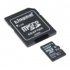
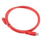
In addition to the materials included in these kits, either a micro-B USB cable, USB-C cable, or a µSD card reader/adapter is required.
- Most users may already have a micro-B USB cable lying around in a drawer somewhere, just make sure that it is capable of transferring data (i.e. not a charging only cable).
- Otherwise, most those familiar with the Raspberry Pi may already have a µSD card reader/adapter.
- A USB-C cable is included with the Sphero RVR; feel free to use that cable instead of purchasing one.
In stock
CAB-10215
USB 2.0 type A to micro USB 5-pin. This is a new, smaller connector for USB devices. Micro USB connectors are about half the …
12In stock
COM-13004
This is an awesome little microSD USB reader. Just slide your microSD card into the inside of the USB connector, then stick t…
8Out of stock
CAB-14743
USB C is fantastic. But until we have converted all our hubs, chargers, and ports over to USB C this is the cable you're goin…
2A computer is also necessary to interface with the Raspberry Pi Zero W in the SparkFun Autonomous kits.
Computer Requirements
- Access to the same network (switch or wireless router) as the Raspberry Pi Zero W used in the kit.
- Serial terminal interface or the ability to modify files from a USB drive to configure the Raspberry Pi Zero W.
- SSH access to interface with the Raspberry Pi Zero W; and then Sphero RVR through the Sphero SDK.
- A web browser with Flash to stream the camera video feed.
Replacement Parts
Click the button above to toggle a list of replacement parts that are available from our catalog.Replacement Parts
In the event that users loose or break any parts, the components of the kits are linked below. (
Unfortunately, the mounting plate and 3/4" 4-40 standoffs for advanced kit are unavailable at this time.)
Main Components:
34 available
SEN-14722
This SparkFun Distance Sensor Breakout utilizes the VL53L1X next generation ToF sensor module to give you the highly accurate…
7Only 9 left!
GPS-14414
The SparkFun XA1110 GPS Breakout is a small I2C-supported module built for easy hookup, thanks to our Qwiic Connect System. E…
5In stock
KIT-15081
To make it even easier to get started, we've assembled this Qwiic Cable Kit with a variety of Qwiic cables from 50mm to 500mm…
1In stock
COM-15051
This is a class 10 16GB microSD memory card, perfect for housing operating systems for single board computers and a multitude…
In stock
DEV-14028
This 8mp camera module is capable of 1080p video and still images that connect directly to your Raspberry Pi. This is the plu…
9In stock
BOB-14685
The SparkFun Qwiic Mux Breakout enables communication with multiple I2C devices that have the same address that makes it simp…
Out of stock
ROB-14391
This is an easy-to-assemble pan/tilt bracket kit that utilizes servos to move on two axes fit for camera and helping-hand app…
4In stock
DEV-15316
The SparkFun Servo pHAT for Raspberry Pi allows your Raspberry Pi to control up to 16 servo motors in a straightforward manne…
115 available
PRT-14272
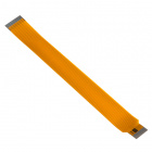
The Raspberry Pi Zero and Zero W are both equipped with a smaller CSI (Camera Serial Interface) port than on a full-sized Ras…
In stock
PRT-10369
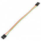
This is a simple four wire cable. Great for jumping from board to board or just about anything else. There is a 4-pin JST RE …
Out of stock
DEV-15470
The Raspberry Pi Zero W is still the Pi you know and love, but at a largely reduced size of only 65mm long by 30mm wide and n…
1Mounting Components:
In stock
PRT-10453
There are your standard Philips-head 4-40 screws. They are 1/4" long and come in packs of ten. This is the screw size we use …
Only 9 left!
PRT-10454
We could talk about how the Zinc used in these nuts is only from the finest old-growth Zinc trees from across the globe and i…
Only 7 left!
PRT-10452
Standard Philips-head 4-40 screws. They are 1/2" long and come in packs of ten. This is the screw size we use in most of the …
In stock
PRT-10228
These are very handy. They are simple angle brackets with one threaded and unthreaded hole. Use them for connecting PCBs at 9…
Optional Accessories
In addition to the items included in the kit here are a few accessories that may be of interest (none of these are required to use the autonomous kits). These products are only recommended for those that prefer to use the Pixel desktop on the Raspberry Pi Zero W and/or want a wall adapter to charge the Sphero RVR battery.
In stock
TOL-13831
This is a high-quality switching 'wall wart' AC to DC 5.1V 2,500mA USB Micro-B wall power supply manufactured specifically fo…
16In stock
TOL-11456
USB is being implemented as a power connection standard more and more these days, but you don't always have a computer on han…
2In stock
COM-14833
This is a class 10 64GB microSD memory card, perfect for housing operating systems for single board computers and a multitude…
In stock
CAB-14274
This is an inexpensive 3-foot-long HDMI to Mini HDMI cable that you can use to hook up your Raspberry Pi Zero W to a suitable…
2In stock
WIG-14271
With Single-Board Computers (SBCs) on the rise, it is a good idea to have an easy way to interface with them. Operating on a …
3In stock
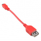
CAB-14276
USB On-The-Go (OTG) is a really useful USB specification! It allows some small devices that would normally be unable to act a…
1Suggested Reading
Below are several tutorials and hookup guides covering various topics that we suggest users get familiar with while following this guide.
Hardware Basics
GPS Basics
The Global Positioning System (GPS) is an engineering marvel that we all have access to for a relatively low cost and no subscription fee. With the correct hardware and minimal effort, you can determine your position and time almost anywhere on the globe.
Connector Basics
Connectors are a major source of confusion for people just beginning electronics. The number of different options, terms, and names of connectors can make selecting one, or finding the one you need, daunting. This article will help you get a jump on the world of connectors.
Hobby Servo Tutorial
Servos are motors that allow you to accurately control the rotation of the output shaft, opening up all kinds of possibilities for robotics and other projects.
Power Basics
Electric Power
An overview of electric power, the rate of energy transfer. We'll talk definition of power, watts, equations, and power ratings. 1.21 gigawatts of tutorial fun!
What is a Battery?
An overview of the inner workings of a battery and how it was invented.
Getting Started with the Raspberry Pi and Python
Serial Communication Basics
Serial Communication
Asynchronous serial communication concepts: packets, signal levels, baud rates, UARTs and more!
Serial Terminal Basics
This tutorial will show you how to communicate with your serial devices using a variety of terminal emulator applications.
I2C and Qwiic Devices
These kits take advantage of our Qwiic system to interface with all the peripheral devices and sensors. For more details, we recommend users familiarize themselves with the Logic Levels and I2C tutorials. Click on the banner above to learn more about our Qwiic products.
Logic Levels
Learn the difference between 3.3V and 5V devices and logic levels.
I2C
An introduction to I2C, one of the main embedded communications protocols in use today.
Raspberry Pi SPI and I2C Tutorial
Learn how to use serial I2C and SPI buses on your Raspberry Pi using the wiringPi I/O library for C/C++ and spidev/smbus for Python.
Qwiic Distance Sensor (VL53L1X) Hookup Guide
The Qwiic VL53L1X time of flight sensor is capable of several modes, as well as having a range of 4M. Let's hook it up and find out just how far away that thing over there is.
Qwiic MUX Hookup Guide
Have a bunch of sensors with the same I2C address? Put them on the Qwiic MUX (TCA9548A) to get them all talking on the same bus!
![shpero logo]()
Sphero has provided an SDK (software development kit) to interface the RVR with different development platforms: the Raspberry Pi, Arduino, and micro:bit. In this tutorial the Raspberry Pi - Python version of the SDK will be utilized.
(
*The Sphero logo, SDK icon, and RVR images are property of Sphero and were pulled from their SDK webpage.)
Hardware Overview
For a brief overview of each component, check out the product videos; otherwise, for a more in-depth look at their operation, check out their hookup guides.
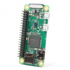
Raspberry Pi Zero W (with Headers)
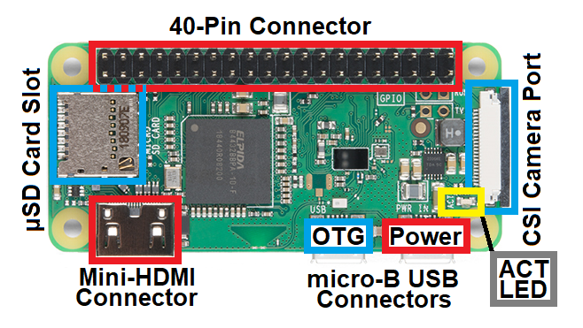
The Raspberry Pi Zero W is the brains of this kit. The Raspberry Pi Zero W is a single board computer (SBC), with WiFi and Bluetooth connectivity, and a CSI camera interface. Below is an annotated image, highlighting components of the hardware that users will want to be familiar with.
Annotated image of Raspberry Pi.
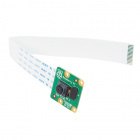
Pi Camera (v2)
The Pi Camera is the eyes of this kit. With a 8MP sensor, the camera module can be used to take high-definition video, as well as stills photographs. Below is an annotated image, highlighting components of the hardware that users will want to be familiar with. Primarily, users should note that the contacts on the ribbon cable face towards the image sensor.
Annotated image of Pi Camera v2.
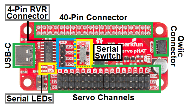
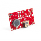
Pi Servo pHat
The Pi Camera is the heart or body of this kit. Excluding the Pi Camera, it interfaces between the Raspberry Pi Zero W and the rest of the hardware included in this kit. Below is an annotated image, highlighting components of the hardware that users will want to be familiar with.
Annotated image of Pi Servo pHat.
Users should note the position of the serial switch, when using the Sphero RVR. Special care should also be taken when connecting the serial UART cable from the Sphero RVR or the servo cables to the Pi Servo pHat. Neither of these connections are polarized and can be easily connected in reverse. The silk screen on the board labels the proper pin connections.
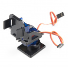
Pan-Tilt Servos
The pan-tilt servo assembly is the neck of the kit, for panning and tilting the Pi Camera. The servos control the orientation of the bracket assembly. Below is an annotated image, highlighting wiring of the hardware that users should be familiar with.
Annotated image of servo wiring harness.
Users should note that the wiring harness (sleeving) may come in a variety of color combinations. The image, above, illustrates the more commonly used colors. (*For more details, check out our hobby servo tutorial.)
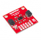
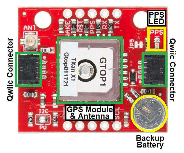
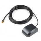
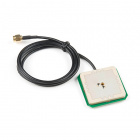
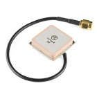
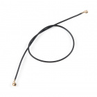
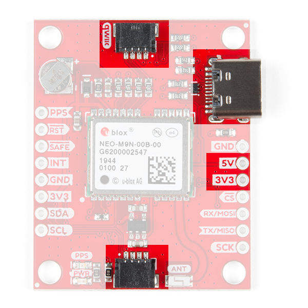
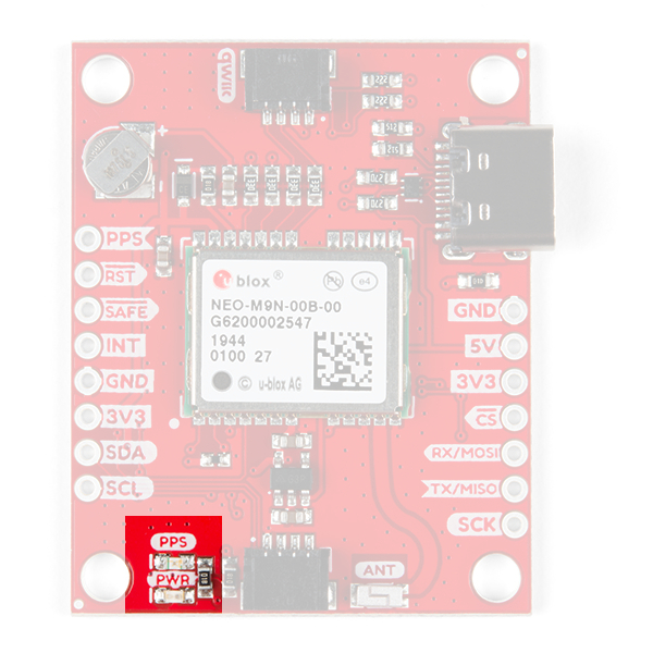
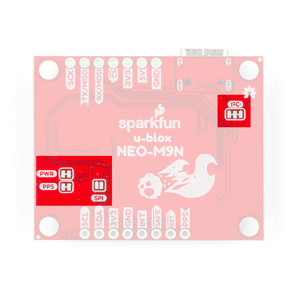
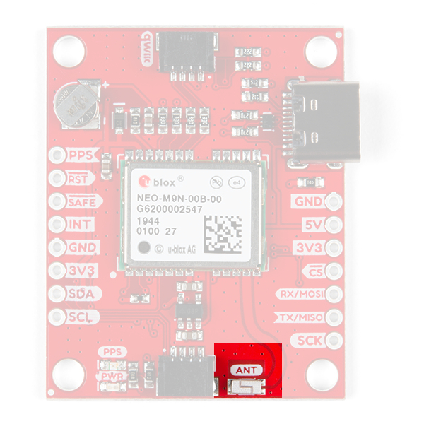
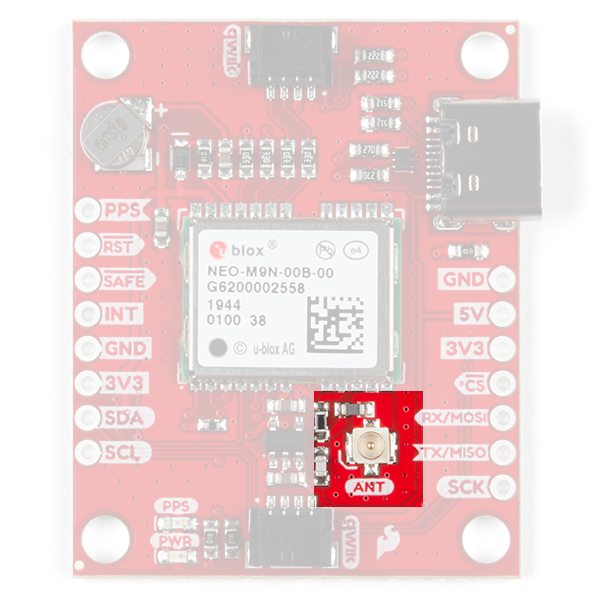
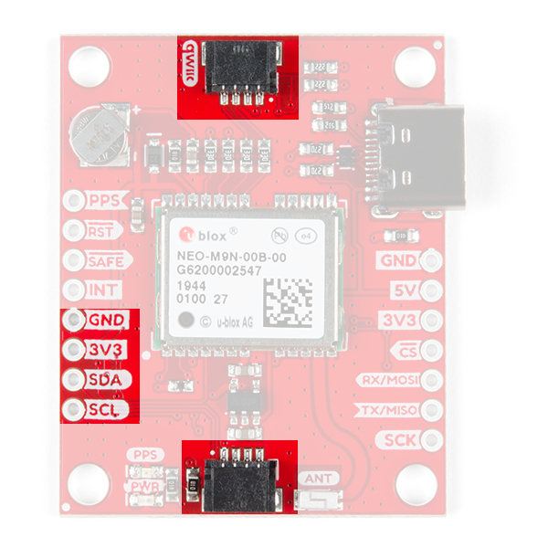
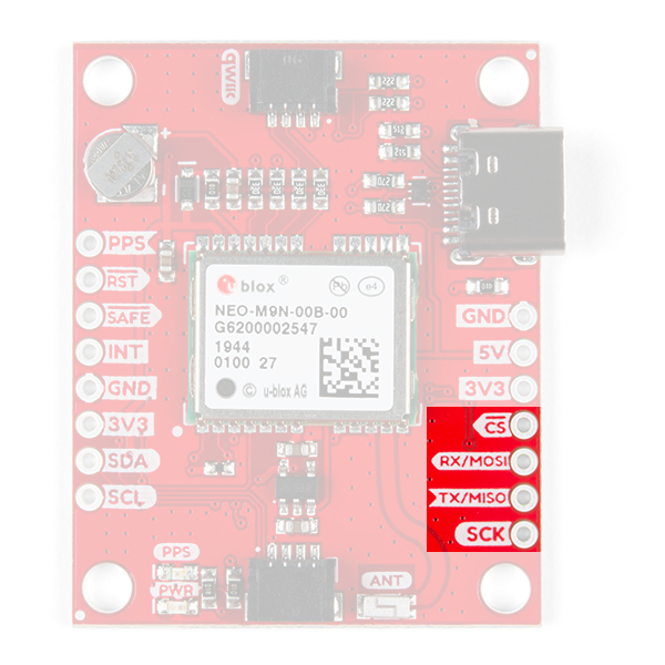
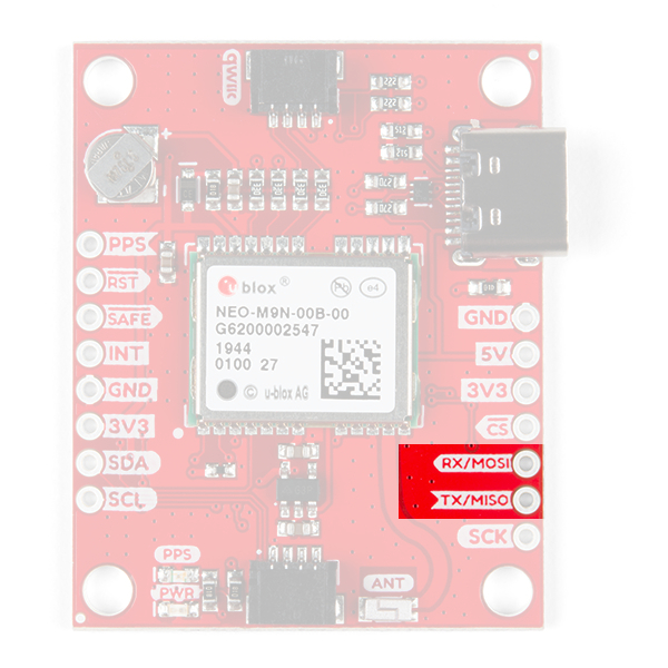
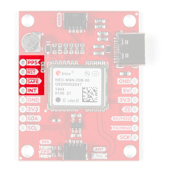
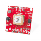
GPS (Titan X1) Module
The GPS module is the geospatial awareness of the kit. Once a lock is acquired, the Titan GPS receiver is able to determine it's location to within a 3m radius. Below is an annotated image, highlighting components of the hardware that users will want to be familiar with.
Annotated image of the GPS Breakout- XA1110 (Qwiic).
Users should note that the PPS LED can be used as a general indicator for when a satellite lock is initially established. Additionally, the GPS module primarily only works when it has a direct view of the sky (i.e. outside; not through a window), to receive satellite signals. (*For more details on GPS receivers, check out our GPS basics tutorial.)
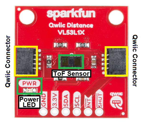
ToF (VL53L1X) Distance Sensors (Advanced Kit Only)
The ToF sensors provide an additional level of geospatial awareness for the kit. The sensor uses IR laser pulses to detect possible obstacles in front of the sensor. Below is an annotated image, highlighting components of the hardware that users will want to be familiar with.
Annotated image of the Distance Sensor Breakout - 4 Meter, VL53L1X (Qwiic).
Users should note that ToF sensors do have performance limitations. For example, the sensor FOV, the target properties (i.e. size, color, reflectivity, etc.), and the ambient light all affect the sensor performance and reliability. (*For more details, check out these related product support articles from Garmin: How the Garmin LIDAR-Lite Products Work with Reflective Surfaces and Effects of distance, target size, aspect, and reflectivity on LIDAR-Lite v3/v3HP returned signal strength .)
Additionally, the product brochure for the VL53L1X ToF module lists that laser beams are safe enough that eye protection is not required. However, we still recommend users avoid staring into the sensor module (or beam path) anyways. (*For more details on the VL53L1X, check out the datasheet.)
Qwiic Distance Sensor (VL53L1X) Hookup Guide
The Qwiic VL53L1X time of flight sensor is capable of several modes, as well as having a range of 4M. Let's hook it up and find out just how far away that thing over there is.
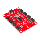
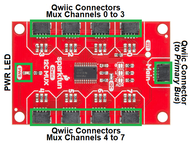
Qwiic Mux (TCA9548A) (Advanced Kit Only)
The mutiplexer (mux) is a simple switch control device for the I2C bus. This component allows users to access the VL53L1X ToF sensors individually, as they share the same I2C address on power up. Below is an annotated image, highlighting components of the hardware that users will want to be familiar with.
Annotated image of the Qwiic Mux Breakout - 8 Channel (TCA9548A).
Qwiic MUX Hookup Guide
Have a bunch of sensors with the same I2C address? Put them on the Qwiic MUX (TCA9548A) to get them all talking on the same bus!
Sphero RVR
Note: These kits do NOT include the Sphero RVR itself. If you do not already have a Sphero RVR, please, make sure to include one with your purchase.
The Sphero RVR is a third-party product that is used as a vehicular platform (or legs) for the SparkFun Autonomous Kits. The primary interface for these kits, is the 4-pin serial UART connection on the Sphero RVR. However, users can also operate the Sphero RVR with a mobile device through Bluetooth with the Sphero EDU app.
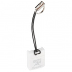
4-pin serial port and USB port on Sphero RVR. (Click to enlarge)
On the front, "port" side of the Sphero RVR, there is the 4-pin serial UART connector and USB port. There is a clear plastic lid covering these connections, which users will need to open. Users should also not the arrangement of the pin connections, as labeled on the printed circuit board (PCB) behind the clear cover.
(*The connector images, SDK icon, and product video are property of Sphero.)
Software Overview: Part 1 - Raspbian OS
Raspbian is a Debian based, Linux operating system (OS) that has been optimized for the Raspberry Pi and it's ARM "CPU". Although Raspbian was primarily created through the efforts of Mike Thompson (mpthompson) and Peter Green (plugwash) as an independent project, it has since been adopted as the official OS of the Raspberry Pi Foundation1.
While there are many aspects of the Raspbian OS and the Raspberry Pi that could be covered, this section will primarily focus on the necessities for the SparkFun autonomous kits. This includes some basic commands and tools for the Raspbian OS.
(*More information on the Raspberry Pi and the Rasbian OS can be found on the Raspberry Pi Foundation's website.)
Suggested Tutorials:
For users who have never used Python, this is a great tutorial to start with.
Raspberry Pi SPI and I2C Tutorial
Learn how to use serial I2C and SPI buses on your Raspberry Pi using the wiringPi I/O library for C/C++ and spidev/smbus for Python.
Command-Line or Terminal
The command-line interface (CLI) or terminal allow users to access the Linux console. From the command-line, users can access and configure all the necessary parts of this kit. To begin, here are a few simple commands that users should familiarize themselves with.
(*More information on the terminal can be found on the Raspberry Pi Foundation's website.)
Privileges
sudo (pronounced sue-due or su-doo)
A prefix that allows users to execute tasks with the security privileges of another user (default: the superuser). Often referred to as superuser do or substitute user do. For this kit, users will primarily need to use these privileges for configuration purposes. Otherwise, the other two most common usages are for shutting down and rebooting the Raspberry Pi.
sudo shutdown now- Commands system to shutdown without a delay.sudo reboot- Commands system to reboot.
Directory Navigation
cd
The change directory command allows users to easily change current working directory in order to navigate through the file system. For this command, there are common usages:
cd ~- Reverts back to the home directory.cd ..- Moves up a directory towards the root folder.cd folder- Moves the current working directory down into folder.
ls
The list command allows users to list files in the current working directory.
pwd
The print working directory command display where in the file system, the current working directory is located.
WiFi
hostname -I
Allows a user to look up the domain name (or IP address) of the system.
ifconfig
A system administrative utility for the network interface configuration. It displays the configuration settings of all network interfaces, including the IP address of the system.
ping
A computer network utility that is used to test the connection to a host (IP address). It displays with the response time for the system to reach the host and ping back (in ms).
ping <IP Address>- Pings IP Address, commonly found in a 192.168.X.X format for home WiFi networks.
(*For other common commands, check out the Raspberry Pi Foundation's website.)
Applications & Tools
nano
Nano is a simple text editor.
nano filename.ext- Modify filename with .ext extension in text editor.- To exit and save changes- Ctrl + X, at prompt Y, and then Enter or Return
i2c-tools
An I2C bus probing tool for Linux.
i2cdetect -y 1- Pings the I2C bus and returns a list of I2C address, where devices have responded.
Depending on how the the I2C device operates, the following commands may not work:
i2cdump -y 1 <I2C Address>- A dump of the values stored in the available registers.i2cget -y 1 <I2C Address> <Register>- A read operation to retrieve a byte stored in a specific register, at the I2C address.i2cset -y 1 <I2C Address> <Register> <Value>- A write operation to set a byte to a specific register, at the I2C address.
Keyboard Commands
- Ctrl + C- Kill process (sends interrupt command).
- Ctrl + D- Exit (sends end of file command).
(*More information on the Linux OS can be found on the Raspberry Pi Foundation's website.)
Note: Before assembling the SparkFun autonomous kit for the Sphero RVR, users should configure their Raspberry Pi and verify the hardware is working. (These steps can be performed with the kit fully assembled; however, avoid any unnecessary troubleshooting or pitfalls, it is recommended that the instructions be followed as laid in this section and the hardware verification section leading up to the Hardware Assembly.)
In this kit, a pre-configured image of Raspbian Buster (release date: 2019-09-26) is provided with all the necessary software packages installed. Unfortunately, there are still a few remaining steps to finish configuring the Raspberry Pi so that it can be accessed remotely.
Overclocking Notice: The image is pre-configured to overclock the Raspberry Pi Zero W and was written to only affects Pi Zero Ws. This configuration modifies the hardware; therefore, even if the µSD card is swapped, the Pi Zero W would still be overclocked on the next boot.
Instructions to remove/undo the overclock configuration are included in the troubleshooting section below. However, users should be aware of this modification. It is necessary to overclock the Raspberry Pi Zero in order to minimize the latency/lag on the camera video feed, while it is being streamed to the web interface and the Sphero SDK is in operation.
Note: In case users accidentally format their SD card in the excitement to get started, need to start over with a fresh image, or if they just want to build their own image... we have got you covered. In the troubleshooting section below, our pre-configured image is available and we have included some basic instructions to build our image from scratch. Users can also download the pre-configured image by clicking on the button below.
Setup the WiFi Connection
The one thing we couldn't do is pre-configure the wireless connection for users. The setup process is detailed in the three separate methods below, depending on user's preferences. In order to provide as many options as conveniently, possible to setup the WiFi, the serial console (or login shell) was left enabled. However, in order for Sphero's SDK to utilize the serial port (without permissions), the serial console must be disabled; therefore, instructions for disabling the login shell are also detailed for each method, in the next section.
WiFi Network Considerations:
- The Raspberry Pi Zero W supports 2.4GHz 802.11n wireless LAN. This is compatible with 802.11b/g/n networks, but only at 2.4GHz; it will not run on a 5GHz WiFi network. If you are a administrator or teacher trying to use this product, be sure to consult your IT department and/or network administrator for assistance with network privileges, compatibility, coverage, etc.
- The web camera interface, in its default configuration, isn't extremely demanding, but it does require a fairly decent network speed and bandwidth. It is recommended that users connect their computers or laptops directly to the network (that the Raspberry Pi is setup on) with an Ethernet cable for the best performance in streaming the camera video feed to avoid any latency or lag.
- At all costs, avoid using USB WiFi dongles! (*Trust me, I spent a week tracking down various ghosts only to learn all the issues stemmed from poor performance with the different WiFi dongles I was using.)
- Additionally, it is preferable to avoid using enterprise networks as they can be troublesome to configure and/or troubleshoot issues.
(*More information on configuring the wireless connectivity can be found on the Raspberry Pi Foundation's website.)
SD Card Reader
This is the simplest method as only two files need to be modified; however, it does require a µSD card adpter/reader. Those that are acquainted with the Raspberry Pi should already have one stashed somewhere (under a stack of papers?). The only downside to this method is that the IP address for the Raspberry Pi won't be accessible. (*There are options to configure a static IP address, but that is beyond the scope of this tutorial.)
Insert the pre-configured µSD card into the adapter and plug the adapter into a computer. Depending on the computer's OS, the µSD card may appear as several USB drives; however, only the boot drive can be accessed/modified.
WiFi Configuration
To configure the WiFi network interface, the wpa_supplicant.conf file needs to be modified in the boot USB drive of the µSD card. On boot up, the kernel will automatically, move the wpa_supplicant.conf file into the appropriate directory of the Linux root file system and use those settings to setup the wireless network. (*On Linux operating systems, the µSD card might get mounted as a disk drive. In that situation, the kernel will probably move the wpa_supplicant.conf file. Therefore, users will need to create a new file.)
SD card shown as a USB Drive (boot partition highlighted). (Click to enlarge)
Modify the wpa_supplicant.conf file using the default text editor of the operating system. If the file isn't there, you can just create a new one (it should just overwrite the previous file when the kernel moves it).
wpa_supplicant.conf file in boot partition of SD card. (Click to enlarge)
Support Tip: On Windows, Notepad or Visual Studio Code are recommended, as they save files with arbitrary file extensions. On MacOS, TextWrangler seems to be the easiest. For Linux, the default system text editor should be fine.
For secured networks, the wpa_supplicant.conf file will should follow this format:
language:bash
ctrl_interface=DIR=/var/run/wpa_supplicant GROUP=netdev
update_config=1
country=<Insert country code here>

network={
 ssid="<Name of your WiFi>"
 psk="<Password for your WiFi>"
}
- Insert the appropriate ISO code of your country (replace
<Insert country code here>). See Wikipedia for a list of country codes (US is the ISO code for the United States of America). - Insert the credentials for the WiFi network that this kit will be utilized on (replace
<Name of your WiFi>and<Password for your WiFi>). - When creating a
wpa_supplicant.conf file, make sure to utilize the .conf file extension.
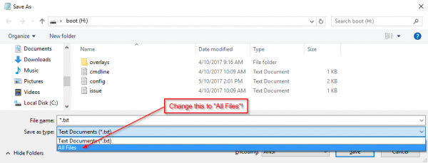
Note: On the Save As... prompt in Notepad for Windows, verify that the file extension type under the Save as type: field is changed from *.txt file to All files. Then you will need to explicitly name the file wpa_supplicant.conf, or Notepad will automatically append the .txt extension to the file name, breaking this functionality.
![file format]() Click the image for a closer look. (Click to enlarge)
Click the image for a closer look. (Click to enlarge)Another option, is to modify .txt extension of the file. On Mac OS and Linux this variation should be equally simple.
Before unplugging the SD card, move on to the Disabling the Serial Console/Login Shell section below.
(*More information on the wpa_supplicant.conf file can be found on the Raspberry Pi Foundation's website.)
Serial Interface
The second method is to use the serial interface (or login shell). For most users, this will be the primary method to configure the Raspberry Pi without needing to purchase additional equipment. Users will need an additional micro-B USB cable or USB-C cable, but one a USB-C cable should already be included with the purchase of a Sphero RVR to charge the battery.
Suggested Tutorials:
For users who have never used a serial terminal and accessed a Raspberry Pi in a headless setup, please review the following tutorials prior to beginning this method. Users will also need to install the CH340C driver on their computers to interface with the Raspberry Pi through a serial terminal.
Serial Terminal Basics
This tutorial will show you how to communicate with your serial devices using a variety of terminal emulator applications.
Using the serial interface (or login shell), allows users to directly interface with the command-line interface (CLI) through another computer's serial terminal. With access to the command-line, users could use a text editor to modify the files mentioned in the previous method; however, that is not the simplest way to configure the Raspberry Pi through the Linux console. A more convenient method is through the raspi-config application, a console based, configuration tool provides a straightforward way to initially configure a Raspberry Pi.
In order to access the serial interface, users must first ensure that they have the proper CH340C driver installed. (*This allows user's computers to recognize the CH340C USB-to-serial adapter on the Pi Servo pHat.) Users will also need have a serial terminal (emulator) installed on their computer (*the serial monitor of the Arduino IDE will not work in this situation). For instructions on how to install the CH340 driver and how to install a serial terminal on their computer, use the tutorials linked above.
Once the driver and serial terminal are installed on the computer, users will need to assemble the Raspberry Pi Zero W, µSD card, Pi Servo pHat, and USB-C cable.
- Carefully, insert the µSD card into the µSD card slot on the Raspberry Pi Zero W.
- Attach the Pi Servo pHat onto the Raspberry Pi Zero W.
- Ensure that the switch on the Pi Servo pHat is moved from
RVR to USB to enable serial communication through the USB-C connector. See hookup guide for more details.
Move serial switch to USB. (Click to enlarge)
- Insert the USB-C cable into the Pi Servo pHat and a USB port on the computer.
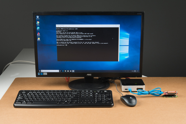
Serial interface setup. (Click to enlarge)
To begin, users will need to access the serial console (login shell) through the serial terminal (emulator) on thier computer. To do this, users should connect to the COM port of the CH340C with a baud rate of 115200. Once connected, press the Enter or Return key to bring up the login promt. (The username and password are the default for the Raspberry Pi: Username = pi and Password = raspberry.)
Login prompt for the Raspberry Pi. (Click to enlarge)
(*More information on setting up a Raspberry Pi (headless) can be found on the Raspberry Pi Foundation's website.)
WiFi Configuration
After the Linux console appears, users only need to enter sudo raspi-config to pull up the configuration tool. (Users outside the US will want to configure their localization settings first.)
Access the Raspberry Pi configuration tool. (Click to enlarge)
To configure the WiFi connection, scroll down to 2 Network Options using the arrow keys and hit enter.
Select 2 Network Options. (Click to enlarge)
Then, select N2 Wi-fi.
Select N2 Wi-fi. (Click to enlarge)
Once prompted, enter the SSID and passphrase for the wifi network.
![enter network credentials]()
Enter the WiFi network credentials. (Click to enlarge)
Before exiting the raspi-config tool, move on to the Disabling the Serial Console/Login Shell section below.
(*More information on the raspi-config tool can be found on the Raspberry Pi Foundation's website. They also provide additional information for setting up the WiFi via the command line)
Note: For users wanting to edit the configuration file directly, use the following command: sudo nano /etc/wpa_supplicant/wpa_supplicant.conf. (To use a preferred text editor, modify the command accordingly.)
Pixel Desktop
The most user friendly way to configure the Raspberry Pi is with the (one-time) setup wizard and configuration application on the Pixel desktop. However, it is the least convenient of the options as it requires the most additional hardware and setup. Users will need the need the following accessories to access the Pixel desktop:
(Users should modify/change the monitor and adapter cable according to the available inputs. Users may also need an additional USB hub.)
Assemble the hardware and accessories as shown below (don't forget to plug the power supply in last).
Desktop setup. (Click to enlarge)
WiFi Configuration
Once the Raspberry Pi has booted to the Linux console, use the startx command to initialize the Pixel desktop and the initial configuration wizard will pop up. Follow the prompts to set-up the WiFi connection. (*The initial configuration wizard is a one-time tool; to bring it up again, use the sudo piwiz command in the Terminal.)
Initial configuration wizard.
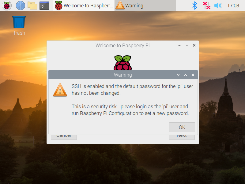
A warning prompt will pop up, if SSH is enabled and the Raspberry Pi is still configured with the default user credentials. User can change the user name and password later, it is fine to close this dialog box for now.
![SSH Warning]()
SSH warning pop up. (Click to enlarge)
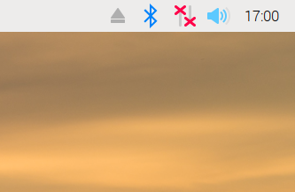
Users can also setup the WiFi connection through the network icon on the taskbar (*the icon changes based on the network connection type and status).
![No Network]() No network connection.
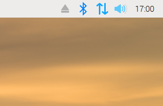
No network connection.![LAN network connection]() LAN network connection.
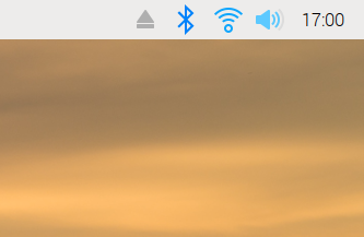
LAN network connection.![WiFi network connection]() WiFi network connection.
WiFi network connection.Note: Again, users can use the Terminal application or the Linux console to modify the files directly or access the raspi-config tool as mentioned in the Serial Interface method.
Once completed, the wizard will want to reboot the Raspberry Pi; click NO and move on to the Disabling the Serial Console/Login Shell section below. (*It is not an issue if users click yes, they will just have to wait for the Raspberry Pi to reboot and have to initialize the Pixel desktop again.)
(*More information on the first-boot setup wizard can be found on the Raspberry Pi Foundation's website.)
Disabling the Serial Console/Login Shell
In order to provide as many options as conveniently, possible to setup the WiFi, the serial console (or login shell) was left enabled. However, in order for Sphero's SDK to utilize the serial port (without permissions), the serial console must be disabled. Therefore, instructions for disabling the login shell are also detailed below.
SD Card Reader
Disabling the Login Shell
To disable the login shell, the cmdline.txt file needs to be modified in the boot USB drive of the µSD card. During boot, the Linux kernel accepts a command-line of parameters set in the cmdline.txt file of the boot partition.
cmdline.txt file in boot partition of SD card. (Click to enlarge)
Below, is the default configuration of the cmdline.txt file in the pre-configured image:
console=serial0,115200 console=tty1 root=PARTUUID=5e3da3da-02 rootfstype=ext4 elevator=deadline fsck.repair=yes rootwait quiet init=/usr/lib/raspi-config/init_resize.sh splash plymouth.ignore-serial-consoles
- Users will need to remove the
console=serial0,115200 portion of the text.
(*More information on the cmdline.txt file can be found on the Raspberry Pi Foundation's website.)
Once both modifications have been made and the µSD card has been safely ejected from the computer, move on to the servo alignment part of this section.
Serial Interface
Disabling the Login Shell
To enable/configure the serial port, scroll down to 5 Interfacing Options using the arrow keys and hit enter.
Select 5 Interfacing Options. (Click to enlarge)
Then, select P6 Serial.
Select P6 Serial. (Click to enlarge)
Once prompted:
Would you like a login shell to be accessible over serial?, select <NO>.
Select <NO> on login shell prompt. (Click to enlarge)
Would you like the serial port hardware to be enabled?, select <YES>.
Select <YES> on serial port prompt. (Click to enlarge)
Once configured, the configuration tool should display:
The serial login shell is disabled
The serial interface is enabled
Select <Ok> to proceed back to the main menu.
Select <Ok> to proceed back to the main menu. (Click to enlarge)
With both the WiFi and serial port modifications made, use the Tab key to select <Finish>.
Select <Finish> on close the raspi-config tool. (Click to enlarge)
When prompted Would you like to reboot now?, select <NO>.
Select <NO> on reboot prompt. (Click to enlarge)
(*More information on the raspi-config tool can be found on the Raspberry Pi Foundation's website.)
Selecting <NO> will allow users to check the IP address of the Raspberry Pi on the WiFi network before rebooting. Users should move on to the Retrieving the IP Address of the Raspberry Pi section below. (*On the next power up, the serial console will be disabled.)
Note: For users wanting to edit the configuration files directly, use the following commands:
sudo nano /etc/wpa_supplicant/wpa_supplicant.conf
sudo nano /boot/config.txt
(
To use a preferred text editor, modify the commands accordingly.)
Pixel Desktop
Disabling the Login Shell
To disable the login shell, click on the raspberry icon on the task bar. Scroll to Preferences>Raspberry Pi Configuration. In the configuration menu, select the Interfaces tab and then disable the Serial Console.
![Pi desktop configuration settings]() Raspberry Pi configuration settings.
Raspberry Pi configuration settings.
(Click to enlarge)
![Interface Settings]() Interface configuration settings. (Click to enlarge)
Interface configuration settings. (Click to enlarge)Note: Again, users can use the Terminal application or the Linux console to modify the files directly or access the raspi-config tool.
Retrieving the IP Address of the Raspberry Pi
Once users are done with the WiFi and serial port configuration process, pull up the IP address for the Raspberry Pi; using the Terminal or Linux console (in not already open). With either the hostname -I or ifconfig commands, users can retrieve the IP address. (*Users who followed the SD card method obviously, will not be able to access the Linux console in order to retrieve the IP address. Don't worry, there are special instructions for these users in the following sections.)
IP address lookup. (Click to enlarge)
Once the IP address has been retrieved, users can shutdown the Raspberry Pi with the sudo shutdown now command.
Shutdown the Raspberry Pi. (Click to enlarge)
Note: Don't forget to make sure that the Raspberry Pi is completely done shutting down before disconnecting the power. This is to avoid corrupting the SD card while the Raspberry Pi is in the middle of its power down cycle. Users should see the ACT LED blink 10 times steadily before a long "on" blink; about 5-10 seconds after, it should be safe to disconnect the power.
![Pi Camera Assembly]()
ACT LED indicating the end of the power down sequence, right before the power can be disconnected. The ACT LED will blink 10 times, followed by a long "on" blink. (Click to enlarge)Remote Access with SSH
Secure Shell (SSH) is a network protocol that allows users to remotely access the Raspberry Pi from another computer, through the WiFi network. Accessing the Raspberry Pi is a relatively simple process:
Suggested Tutorials:
For users who have never accessed a Raspberry Pi in a headless setup, please review this tutorial.
SSH Client Access
- To access the Raspberry Pi, users will need the IP address of the Pi. (*For users that used the SD card method, don't worry. The Raspberry Pi can still be accessed; however, only one Raspberry Pi can be powered at a time.)
- More information on determining the Raspberr Pi's IP address can be found on the Raspberry Pi Foundation's website.
- On the computer used to remotely access the Pi, pull up the SSH Client, Terminal, Linux Console, or Command Prompt (Windows 10 with October 2018 Update or later).
Use the following command to test if the Raspberry Pi can be accessed:
ping <IP Address>ping raspberrypi.local (if the SD card method was used)
![ping device]()
ping the Raspberry Pi to confirm that is has connected to the WiFi network. (Click to enlarge)
- If a connection is made, a print out of the response times will display. (If needed, press Ctrl+C to kill the process.)
To SSH into the Raspberry Pi, use the following command:
ssh pi@<IP Address> (pi is the username of the account that will be accessed.)ssh pi@raspberrypi.local (if the SD card method was used)
![ping device]()
ssh into the Raspberry Pi, using the default credentials. (Click to enlarge)
- The Raspberry Pi will prompt users for the password for the
pi user. The username and password are the default for the Raspberry Pi:
- Username =
pi - Password =
raspberry
(*More information on remotely accessing the Raspberry Pi through SSH can be found on the Raspberry Pi Foundation's website. Additionally, there also is information on other remote access methods.)
Software Overview: Part 2 - Python
Python is a popular and fairly intuitive programming language, used by various industries, including Fortune 100 companies. What makes Python so popular isn't the simplicity of the high-level, language architecture, but rather the adaptability to deploy code across various platforms. Python is an interpreted language, which essentially means that as long as a platform (i.e. computer, server, etc.) has an interpreter, it can execute Python code. (*This is an over generalization of how Python operates; for more details check out this GeeksforGeeks article and the Inside The Python Virtual Machine eBook.) A perfect example of Python's cross-platform functionality is that a program written on a Windows PC does not need to be rewritten to work on a Mac or a Linux machine. This adaptability, has allowed Python spread across various markets and become widely adopted. Another benefit is that Python is developed under an OSI-approved open source license, making it freely usable and distributable, even for commercial use. Now, there are a few drawbacks to working with Python, but they are greatly overshadowed by its benefits for the purposes of this kit.
(*More information on the Python can be found on the Python Software Foundation's website.)
How is Python used with the Raspberry Pi?
Specifically, with the Raspberry Pi, Python allows users to interact with the physical world through the general purpose input/outputs (GPIO). The GPIO is an interface that users can electrically connect various sensors and devices to, which can be operated through the Raspberry Pi, using Python. Essentially, this means that:
- Users can connect a GPS module (Like the one included in these kits) to the GPIO of the Raspberry Pi.
- Through the Raspbian OS, users can interface and control the GPIO with Python.
- This grants users direct access to the GPS module with Python, allowing users to retrieve GPS coordinate data.
Now that we have been established that Python is the software, which is used to interface with the hardware connected to the Raspberry Pi. This section will briefly overview the Python application and how it is used with this kit. (This section, barely skims the surface of Python and how it can be used with the Raspberry Pi.)
(*More information on using Python with the Raspberry Pi can be found on the Raspberry Pi Foundation's website.)
Suggested Tutorials:
For users who have never used Python, this is a great tutorial to start with.
Raspberry gPIo
How to use either Python or C++ to drive the I/O lines on a Raspberry Pi.
Raspberry Pi SPI and I2C Tutorial
Learn how to use serial I2C and SPI buses on your Raspberry Pi using the wiringPi I/O library for C/C++ and spidev/smbus for Python.
Installing Packages
pip3
A package management system for installing Python 3 packages hosted on PyPI.
pip3 install <Package Name>- Installs a Python package (and any linked dependencies) hosted on PyPI.pip3 uninstall <Package Name>- Removes a Python package hosted on PyPI.pip3 install --upgrade <Package Name>- Updates a Python package hosted on PyPI.
Python Applications and Tools
ipython3
A simple shell program for Python 3 to write and execute line by line Python instructions.
- Once inside the shell, users can execute instructions line by line as if it were an actual Python script. This is useful for:
- Code development.
- Catching errors.
- Debugging, where an output error might be suppressed.
- On loops (i.e.
for or while) and if statements, users will need to hit Enter twice to close the loop or statement. - Ctrl + C- Terminate proccess (or keyboard interrupt).
exit() or Ctrl + D- Exit shell.%save <Filename> <Line Numbers>- Save Line Numbers to Filename.py%save -r test 1-10- Saves lines 1 to 10 to test.py
python3
Executes programs using Python 3.
python3 filename.py- Executes filename.py with Python 3.- Ctrl + C- Terminate proccess/script (or keyboard interrupt).
pipenv
A packaging tool for Python that is designed to consolidate and simplify a development workflow. This is primarily for the Sphero SDK.
pipenv shell- Launches shell for virtual environment.exit or Ctrl + D- Exit shell.
Keyboard Commands
- Ctrl + C- Kill process (sends interrupt command).
- Ctrl + D- Exit (sends end of file command).
Initial Hardware Tests
This section contains instructions for testing all the hardware in the kit to verify that everything is working. These are individualized tests for the hardware, which can be used to help troubleshoot these devices later on. It is recommended that users test components individually (as laid out in this section) to reduce the number of unknown variables.
Raspberry Pi
The first component to test is the Raspberry Pi. Assemble the Raspberry Pi, Pi Servo pHat, and SD card as shown below. Users can power the device either through the 4-pin connector or the USB-C cable on the Pi Servo pHat.
Assembly for testing the Raspberry Pi Zero W. (Click to enlarge)
It should power on, boot, connect to the WiFi network (configured previously), and be accessible through the SSH protocol when working properly.
Power and Boot
Once powered, you should see a green LED turn on. While the Raspberry Pi Zero W is booting, the green will flash indicating that the SD card is being accessed.
An example with the ACT LED operating properly. (Click to enlarge)
WiFi Network Connection
It will take a minute or two for the Raspberry Pi to finish booting and connect to the WiFi network. Once connected to the WiFi network, the Raspberry Pi can either be pinged or mapped from another computer (on the same network). The simplest method is to ping the Raspberry Pi using the following command in your Terminal or Command Prompt. Users that have the IP address of the Raspberry Pi, should ping that IP address; otherwise, if users have forgotten or used the SD card method, they can ping the domain name raspberrypi.local. The limiting factor to using the domain name, is that only ONE Raspberry Pi can be on the network at a time; otherwise, users will run into contention issues and will likely connect to the wrong Raspberry Pi.
ping <IP ADDRESS> or ping raspberrypi.local
![Ping Raspberry Pi]()
Verifying Raspberry Pi is on WiFi network. (Click to enlarge)
(*More information on determining the Raspberr Pi's IP address can be found on the Raspberry Pi Foundation's website.)
SSH Access
Once users have pinged the Raspberry Pi and verified that it is connected to the network, they can access it remotely through the SSH protocol. On a modern computer OS, this can be done through the Terminal or Command-Prompt. However, users with more outdated systems will need to use an SSH client like Putty (see the Headless Raspberry Pi Setup tutorial). Using the Command-Prompt or Terminal, enter the following command:
ssh pi@<IP ADDRESS> or ssh pi@raspberrypi.local
Again, if users have forgotten the IP address or used the SD card method, they can ping the domain name raspberrypi.local (the same limiting factor applies).
![SSH Login]()
SSH access and login to Raspberry Pi. (Click to enlarge)
Once connected, users will be prompted to login. If the login prompt doesn't show up after few moments, press the Enter or Return key to bring up the login prompt. The username and password are the default for the Raspberry Pi: Username = pi (used in ssh command) and Password = raspberry.
Support Tip:For users creating a new SSH connection, there may also be an authentication prompt. Type yes to continue.
The authenticity of host '[IP Address]' can't be established.
ECDSA key fingerprint is SHA256: [Bunch of numbers and letters].
Are you sure you want to continue connecting (yes/no)?
-
To retrieve the IP address of the Pi, once users are connected, use the
ifconfig or hostname -I commands as mentioned in the Software Overview: Part 1 - Raspbian OS section.
Once users have remotely access the Raspberry Pi, the test is complete. Shutdown the Raspberry Pi using the sudo shutdown now command as mentioned in the Software Overview: Part 1 - Raspbian OS section. (*Remember... before unplugging the power or removing the SD card, be sure to verify that the Raspberry Pi has completely shutdown to avoid corrupting the SD card.)
![servo test assembly]() Shutting down the Raspberry Pi. (Click to enlarge)
Shutting down the Raspberry Pi. (Click to enlarge)![Pi Camera Assembly]() ACT LED indicating the end of the power down sequence, right before the power can be disconnected. (Click to enlarge)
ACT LED indicating the end of the power down sequence, right before the power can be disconnected. (Click to enlarge)Pi Camera & Camera Web Interface
Once users have verified that the they can remotely access the Raspberry Pi, it is time to test the Raspberry Pi camera web interface. Connect the Raspberry Pi camera to the Raspberry Pi Zero W as shown below (take note of what side the gold contacts are on).
![servo test assembly]()
Pi Camera test assembly. (Click to enlarge)
![Pi Camera Assembly]()
Pi Camera (v2) attached to a Raspberry Pi.
Close ups of the Pi Camera (v2) and Raspberry Pi with the camera cable. (Click to enlarge)
Once the camera is connected and the Raspberry Pi is powered on (via the Pi Servo pHat), wait for the Raspberry Pi to finish booting and connecting to the WiFi network. Then, remotely access the Raspberry Pi using the SSH protocol from another computer and login.
![SSH Login]()
SSH access and login to Raspberry Pi. (Click to enlarge)
Once logged in, users will want to test the Pi Camera web interface.
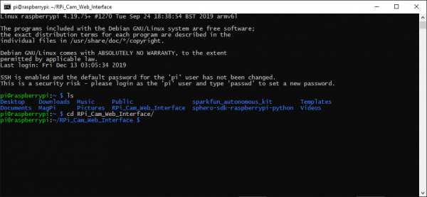
Change the current working directory to the RPI_Cam_Web_Interface folder.
- Users can use
cd RPI_Cam_Web_Interface from the home directory. - Otherwise, user can also
cd ~/RPI_Cam_Web_Interface from any other location.
Change the directory to the RPI_Cam_Web_Interface folder. (Click to enlarge)
- Initializing and terminating the web camera interface is simple. Below, are the two available commands to use, once users are in the
RPI_Cam_Web_Interface directory:
./start.sh - Start the Camera./stop.sh - Stop the Camera
Use ./start.sh to initialize the stream for the video feed from the Pi Camera.
Start the video feed from the Pi Camera to the web interface. (Click to enlarge)
- While the web camera interface is running, pull up a web browser with enter the following URL:
<IP ADDRESS>/html. (Again, if users have forgotten the IP address or used the SD card method, they can use the domain name raspberrypi.local in place of the <IP address>.) Users should see something similar to the images below.
Examples of the Pi Camera's web interface. (Click to enlarge)
- Users should be able to see the video feed from the Pi Camera on the webpage.
Once users are finished testing the Pi Camera, use ./stop.sh to terminate the video feed.
End the video feed from the Pi Camera to the web interface. (Click to enlarge)
Once video feed is terminated, shutdown the Raspberry Pi using the sudo shutdown now command as mentioned in the Software Overview: Part 1 - Raspbian OS section. (*Remember... before unplugging the power or removing the SD card, be sure to verify that the Raspberry Pi has completely shutdown to avoid corrupting the SD card.)
![servo test assembly]() Shutting down the Raspberry Pi. (Click to enlarge)
Shutting down the Raspberry Pi. (Click to enlarge)![Pi Camera Assembly]() ACT LED indicating the end of the power down sequence, right before the power can be disconnected. (Click to enlarge)
ACT LED indicating the end of the power down sequence, right before the power can be disconnected. (Click to enlarge)Pi Servo pHat
The Pi Servo pHat plays a central roll for connecting everything to the Raspberry Pi. After testing the Raspberry Pi, above, users should have already verified that power is being passed through the Pi hat (pHat). This section will focus on the servo control of the Pi Servo pHat; the following Qwiic Devices section will verify the I2C functionality through the pHat.
Qwiic Test
Although the Pi Servo pHat isn't actally a Qwiic device, the servo controller IC does use the I2C bus. A simple test to verify that it is responding is to use the i2cdetect -y 1 command to ping the I2C bus. By default, the servo controller IC should be at the 0x40 I2C address. If the general call address is enabled, the 0x70 I2C address may appear as well.
Ping the I2C bus. (Click to enlarge)
Servo Test
This test will verify that the Pi Servo pHat can control the servos and that the servos are functioning properly. Additional instructions are also provided, below, to assist in pre-alignment of the pan-tilt servos prior to assembly. This will help to avoid damaging the servo on their inaugural operation as well as streamline the assembly process.
Users will need to assemble the Raspberry Pi Zero W with the Pi Servo pHat and attach a servo to Channel 0. Double check that the wiring is aligned properly.
Assembly for the individual servo test. (Click to enlarge)
Once the everything is assembled and the Raspberry Pi is powered on, wait for the Raspberry Pi to finish booting and connecting to the WiFi network. Then, remotely access the Raspberry Pi using the SSH protocol from another computer and login.
![SSH Login]()
SSH access and login to Raspberry Pi. (Click to enlarge)
Once logged in, users will want to run the servo example code.
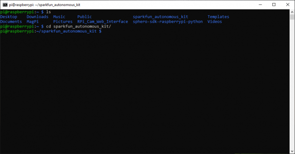
Change the current working directory to the sparkfun_autonomous_kit folder.
- Users can use
cd sparkfun_autonomous_kit from the home directory. - Otherwise, user can also
cd ~/sparkfun_autonomous_kit from any other location.
Change the directory to the sparkfun_autonomous_kit folder. (Click to enlarge)
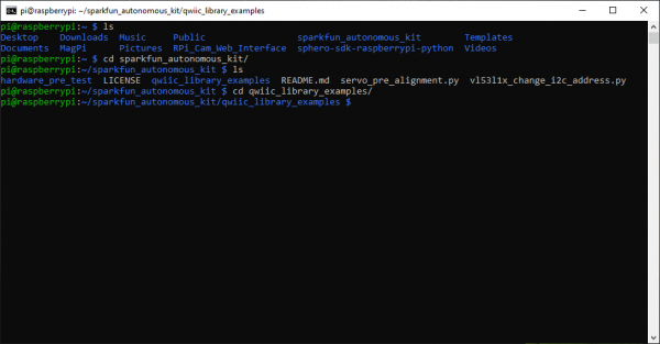
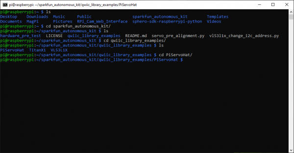
Inside the sparkfun_autonomous_kit directory is the qwiic_library_examples folder. Change the current working directory to the qwiic_library_examples folder.
- Use the
ls command list the files in the directory and to verify it is there. - Use the
cd qwiic_library_examples command.
Change the directory to the qwiic_library_examples folder. (Click to enlarge)
Inside the qwiic_library_examples directory is the PiServoHat folder. Change the current working directory to the PiServoHat folder.
- Use the
ls command list the files in the directory and to verify it is there. - Use the
cd PiServoHat command.
Change the directory to the PiServoHat folder. (Click to enlarge)
Inside the PiServoHat directory is the ex1_full_sweep_with_90_deg_servo.py example code. Execute the example code.
- Use the
ls command list the files in the directory and to verify it is there. - To execute the example code, run
python3 ex1_full_sweep_with_90_deg_servo.py.
Execute the ex1_full_sweep_with_90_deg_servo.py example code. (Click to enlarge)
- If it is working properly, users should see the servo moving back and forth. It may be helpful to attach one of the servo horns to verify that the swing range is ~90°. Once users are finished testing, use Ctrl+C to terminate the script.
Running the servo test example. (Click to enlarge)
- Shutdown the Raspberry Pi using the
sudo shutdown now command as mentioned in the Software Overview: Part 1 - Raspbian OS section. Then, swap the servos. (*Remember... before unplugging the power or removing the SD card, be sure to verify that the Raspberry Pi has completely shutdown to avoid corrupting the SD card.)
- Users should shutdown and unplug the Raspberry Pi before swapping the servos.
- Hot swapping the servos (swapping the servos while the Raspberry Pi is powered) can create a power failure issue, which could possibly corrupt the SD card.
![servo test assembly]() Shutting down the Raspberry Pi. (Click to enlarge)
Shutting down the Raspberry Pi. (Click to enlarge)![Pi Camera Assembly]() ACT LED indicating the end of the power down sequence, right before the power can be disconnected. (Click to enlarge)
ACT LED indicating the end of the power down sequence, right before the power can be disconnected. (Click to enlarge)
- Repeat the process to test the other servo.
- To jump directly to the
PiServoHat directory:- Users can use
cd sparkfun_autonomous_kit/qwiic_library_examples/PiServoHat from the home directory. - Otherwise, user can also
cd ~/sparkfun_autonomous_kit/qwiic_library_examples/PiServoHat from any other location.
That completes the Pi Servo pHat hardware test, shutdown the Raspberry Pi using the sudo shutdown now command as done previously. Users can choose pre-align their servos (recommended) or move on to testing the Qwiic devices.
Aligning Servos (Optional)
To help users avoid damaging their servos for the pan-tilt bracket, an example pre-alignment code has been provided. The example code will align the pan (or horizontal movement) servo at 45° and the tilt (or vertical movement) servo at 37°. To pre-align the servos, users will need to assemble the Raspberry Pi Zero W with the Pi Servo pHat and two servos.
Assembly for servo pre-alignment. (Click to enlarge)
Once the everything is assembled and the Raspberry Pi is powered on, wait for the Raspberry Pi to finish booting and connecting to the WiFi network. Then, remotely access the Raspberry Pi using the SSH protocol from another computer and login.
![SSH Login]()
SSH access and login to Raspberry Pi. (Click to enlarge)
Once logged in, users will want to run the servo pre-alignment example.
Change the current working directory to the sparkfun_autonomous_kit folder.
- Users can use
cd sparkfun_autonomous_kit from the home directory. - Otherwise, user can also
cd ~/sparkfun_autonomous_kit from any other location.
Change the directory to the sparkfun_autonomous_kit folder. (Click to enlarge)
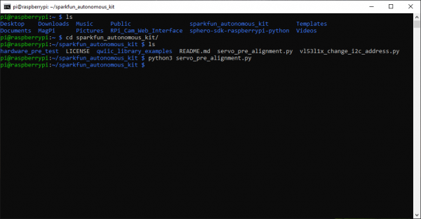
Inside the sparkfun_autonomous_kit directory is the servo_pre_alignment.py example code. Execute the example code.
- Use the
ls command list the files in the directory and to verify it is there. - To execute the example code, run
python3 servo_pre_alignment.py.
Execute the servo_pre_alignment.py example code. (Click to enlarge)
- The example code will align the pan (or horizontal movement) servo at 45° and the tilt (or vertical movement) servo at 37°. This position is ideal for the standard forward facing position. The Channel 0 is configured for the pan servo and Channel 1 is configured for the tilt servo.
![90 deg postion]() Standard forward facing or 90° postion.
Standard forward facing or 90° postion.
(Click to enlarge)
![standard position on chassis]() Standard forward facing position on chassis.
Standard forward facing position on chassis.
(Click to enlarge)
- Users should mark these positions with a marker. These marks should streamline the assembly process. Additionally, aligning the tilt servo at 37°, will hopefully prevent it from over-extending its position and thereby striping out the gears when it is moved to 0° or 90°.
![Marking Servo]()
Marking the position on a servo. (Click to enlarge)
![Marked Servo]()
A marked servo. (Click to enlarge)
- Once completed, shutdown the Raspberry Pi using the
sudo shutdown now command as mentioned in the Software Overview: Part 1 - Raspbian OS section. (*Remember... before unplugging the power or removing the SD card, be sure to verify that the Raspberry Pi has completely shutdown to avoid corrupting the SD card.)
![servo test assembly]() Shutting down the Raspberry Pi. (Click to enlarge)
Shutting down the Raspberry Pi. (Click to enlarge)![Pi Camera Assembly]() ACT LED indicating the end of the power down sequence, right before the power can be disconnected. (Click to enlarge)
ACT LED indicating the end of the power down sequence, right before the power can be disconnected. (Click to enlarge)
Qwiic Devices
By now, users should have verified the functionality of the Raspberry Pi, the Pi Servo pHat, and the I2C bus. This section will verify the I2C functionality from the Pi Servo pHat with each Qwiic device, individually.
Qwiic Test
A simple test for users to check the connectivity of any attached I2C devices can be performed by pinging them with i2c-tools. In the command-line enter i2cdetect -y 1 and a readout of any detected devices will appear. For example, the servo controller IC should be at the 0x40 I2C address. (If the general call address is enabled, the 0x70 I2C address may appear as well.)
Ping the I2C bus with just the Pi Servo pHat. (Click to enlarge)
This is a table of the default I2C addresses for the hardware included in these kits.
| Hardware |
Pi Servo pHat
(Not a Qwiic Device) | Titan GPS Module | Qwiic Mux (TCA9548A) | VL53L1X ToF Sensor |
|---|
| Default I2C Address | 0x40 | 0x10 | 0x70 | 0x29 |
|---|
GPS (Titan X1) Module
For this test users will want to be in a location with their WiFi network coverage and a clear view of the sky. Access to an open window, is a feasible option; however, it is not guaranteed to work. For example, on the bottom floor of a tall building, even if users stuck the GPS module out the window, it may still have issues getting a positional lock. If possible, a clearing or field, just outside a house or building, where there is still WiFi coverage is the ideal testing location.
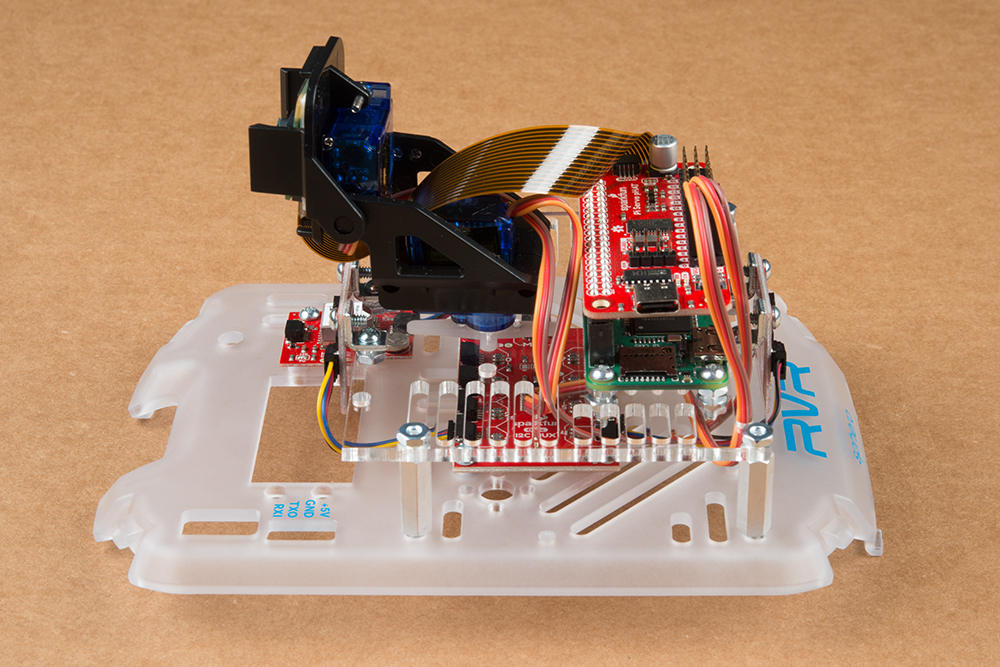
Users will need to assemble the Raspberry Pi Zero W with the Pi Servo pHat and attach the Titan (X1) GPS module using a Qwiic cable. To power the setup, users can use 4-pin UART cable and the Sphero RVR to make the test setup portable and carry it outside.
Portable assembly for testing the GPS module. (Click to enlarge)
Once the everything is assembled, to power the Raspberry Pi, press the power button on the side of the Sphero RVR. Wait for the Raspberry Pi to finish booting and connecting to the WiFi network. Then, remotely access the Raspberry Pi using the SSH protocol from another computer and login.
![SSH Login]()
SSH access and login to Raspberry Pi. (Click to enlarge)
Once logged in, users will want to run the GPS example code.
Change the current working directory to the sparkfun_autonomous_kit folder.
- Users can use
cd sparkfun_autonomous_kit from the home directory. - Otherwise, user can also
cd ~/sparkfun_autonomous_kit from any other location.
Change the directory to the sparkfun_autonomous_kit folder. (Click to enlarge)
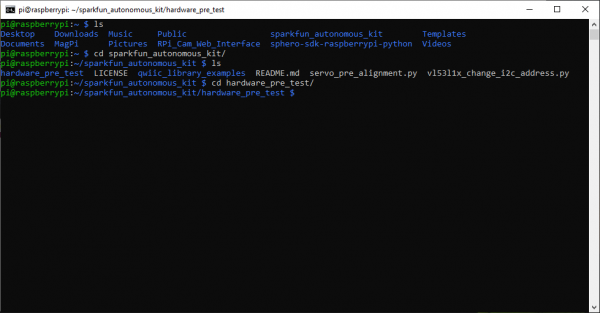
Inside the sparkfun_autonomous_kit directory is the hardware_pre_test folder. Change the current working directory to the hardware_pre_test folder.
- Use the
ls command list the files in the directory and to verify it is there. - Use the
hardware_pre_test command.
Change the directory to the hardware_pre_test folder. (Click to enlarge)
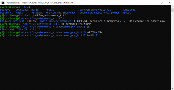
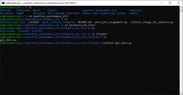
Inside the hardware_pre_test directory is the TitanX1 folder. Change the current working directory to the TitanX1 folder.
- Use the
ls command list the files in the directory and to verify it is there. - Use the
cd TitanX1 command.
Change the directory to the TitanX1 folder. (Click to enlarge)
Inside the TitanX1 directory is the gps_data.py example code. Execute the example code.
- Use the
ls command list the files in the directory and to verify it is there. - To execute the example code, run
python3 gps_data.py.
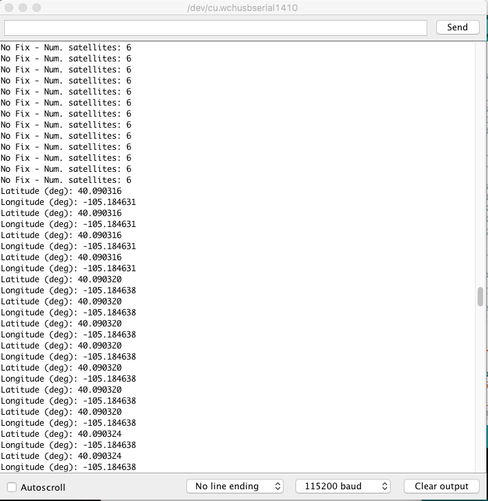
Execute the gps_data.py example code. (Click to enlarge)
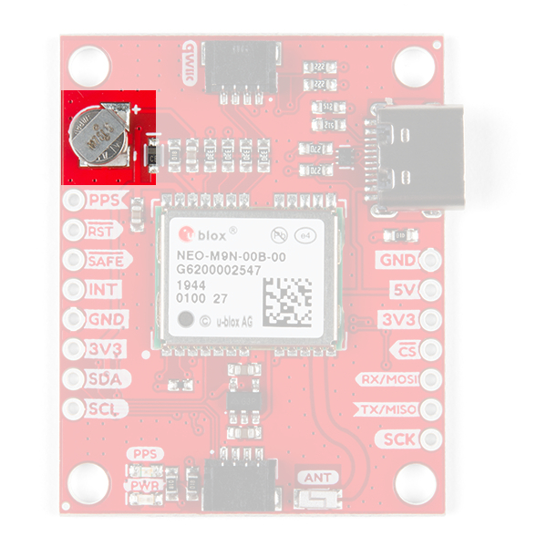
If it is working properly, users should see clear readout from the GPS module. It may take a minute or two for the GPS module to get an initial lock; the PPS LED is usually a good general indicator of a possible initial lock on the modules position. (The PPS LED is not necessarily an absolute indication that the module has a fix on its position.)
Additionally, the backup battery has enough energy for the GPS module to store pertinent data for a few days. Therefore, if the module has had a recent positional lock in the area, it may re-acquire its position a lot quicker.
Once users are finished testing, use Ctrl+C to terminate the script.
![running gps example]()
Running the GPS test example. (Click to enlarge)
![PPS LED]()
PPS LED blinking. (Click to enlarge)
- That completes the GPS hardware test. Shutdown the Raspberry Pi using the
sudo shutdown now command as mentioned in the Software Overview: Part 1 - Raspbian OS section. (*Remember... before unplugging the power or removing the SD card, be sure to verify that the Raspberry Pi has completely shutdown to avoid corrupting the SD card.)
- Users should shutdown and unplug the Raspberry Pi before swapping the servos.
- Hot swapping the servos (swapping the servos while the Raspberry Pi is powered) can create a power failure issue, which could possibly corrupt the SD card.
![servo test assembly]() Shutting down the Raspberry Pi. (Click to enlarge)
Shutting down the Raspberry Pi. (Click to enlarge)![Pi Camera Assembly]() ACT LED indicating the end of the power down sequence, right before the power can be disconnected. (Click to enlarge)
ACT LED indicating the end of the power down sequence, right before the power can be disconnected. (Click to enlarge)
Users who purchase the Basic kit should move on to the Hardware Assembly section. Otherwise, users that purchased the Advanced kit should continue below to finish testing the VL53L1X ToF sensors and the Qwiic Mux.
ToF (VL53L1X) Distance Sensors (Advanced Kit Only)
For this test users will want to be in an indoor location. Although, the ToF sensor should be more than powerful enough to operate in daylight conditions, it would be advisable to test indoors to remove ambient light as a variable for the testing conditions. Users will need to assemble the Raspberry Pi Zero W with the Pi Servo pHat and attach one of the VL53L1X ToF distance sensors using a Qwiic cable.
Assembly for testing the VL53L1X ToF distance sensor. (Click to enlarge)
Once the everything is assembled, to power the Raspberry Pi and wait for it to finish booting and connecting to the WiFi network. Then, remotely access the Raspberry Pi using the SSH protocol from another computer and login.
![SSH Login]()
SSH access and login to Raspberry Pi. (Click to enlarge)
Once logged in, users will want to run the distance sensor example code.
Change the current working directory to the sparkfun_autonomous_kit folder.
- Users can use
cd sparkfun_autonomous_kit from the home directory. - Otherwise, user can also
cd ~/sparkfun_autonomous_kit from any other location.
Change the directory to the sparkfun_autonomous_kit folder. (Click to enlarge)
Inside the sparkfun_autonomous_kit directory is the qwiic_library_examples folder. Change the current working directory to the qwiic_library_examples folder.
- Use the
ls command list the files in the directory and to verify it is there. - Use the
cd qwiic_library_examples command.
Change the directory to the qwiic_library_examples folder. (Click to enlarge)
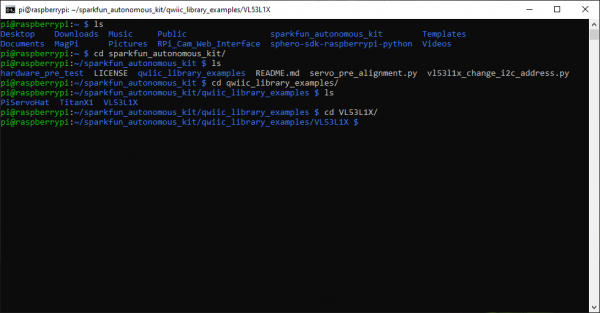
Inside the qwiic_library_examples directory is the VL53L1X folder. Change the current working directory to the VL53L1X folder.
- Use the
ls command list the files in the directory and to verify it is there. - Use the
cd VL53L1X command.
Change the directory to the VL53L1X folder. (Click to enlarge)
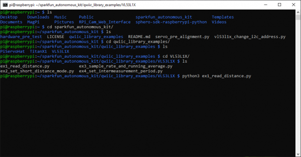
Inside the VL53L1X directory is the ex1_read_distance.py example code. Execute the example code.
- Use the
ls command list the files in the directory and to verify it is there. - To execute the example code, run
python3 ex1_read_distance.py.
Execute the ex1_read_distance.py example code. (Click to enlarge)
- If it is working properly, users should see clear readout from the VL53L1X ToF distance sensor. If users have a cellphone camera that does not have an IR filter, the camera can be used to detect the pulses of the IR laser. Once users are finished testing, use Ctrl+C to terminate the script.
![running example code]() Running the distance sensor test code.
Running the distance sensor test code.
(Click to enlarge)![detecting IR laser]() Detecting pulses of IR laser. (Click to enlarge)
Detecting pulses of IR laser. (Click to enlarge)
- Shutdown the Raspberry Pi using the
sudo shutdown now command as mentioned in the Software Overview: Part 1 - Raspbian OS section. Then, swap the ToF sensors. (*Remember... before unplugging the power or removing the SD card, be sure to verify that the Raspberry Pi has completely shutdown to avoid corrupting the SD card.)
- Users should shutdown and unplug the Raspberry Pi before swapping the sensors.
![servo test assembly]() Shutting down the Raspberry Pi. (Click to enlarge)
Shutting down the Raspberry Pi. (Click to enlarge)![Pi Camera Assembly]() ACT LED indicating the end of the power down sequence, right before the power can be disconnected. (Click to enlarge)
ACT LED indicating the end of the power down sequence, right before the power can be disconnected. (Click to enlarge)
- Repeat the process to test the other ToF sensor.
- To jump directly to the
VL53L1X directory:- Users can use
cd sparkfun_autonomous_kit/qwiic_library_examples/VL53L1X from the home directory. - Otherwise, user can also
cd ~/sparkfun_autonomous_kit/qwiic_library_examples/VL53L1X from any other location.
This completes the VL53L1X ToF distance sensor test, shutdown the Raspberry Pi using the sudo shutdown now command as done previously. Users should move on to testing the Qwiic Mux, below.
Qwiic Mux (Advanced Kit Only)
This is the last and final test! The VL53L1X ToF distance sensor has a "software" configurable I2C address; however it is "volatile", upon re-powering the device, it will automatically reset to the default I2C address. This is where the Qwiic Mux comes in. It is used to isolate the sensors, initially, so that the I2C address of one of the sensors can be reconfigured on power up. Again, since this test will use the VL53L1X sensors, users will want to be in an indoor location.
Users will need to assemble the Raspberry Pi Zero W with the Pi Servo pHat and attach the Qwiic Mux with a Qwiic cable. Then, on the Qwiic Mux, users should attach one of the VL53L1X ToF distance sensors to channels 0or4, using the Qwiic cables.
Assembly for testing the Qwiic Mux; use either channel 0 or 4. (Click to enlarge)
Once the everything is assembled, to power the Raspberry Pi and wait for it to finish booting and connecting to the WiFi network. Then, remotely access the Raspberry Pi using the SSH protocol from another computer and login.
![SSH Login]()
SSH access and login to Raspberry Pi. (Click to enlarge)
Once logged in, users will want to run the VL53L1X address change example code.
Change the current working directory to the sparkfun_autonomous_kit folder.
- Users can use
cd sparkfun_autonomous_kit from the home directory. - Otherwise, user can also
cd ~/sparkfun_autonomous_kit from any other location.
Change the directory to the sparkfun_autonomous_kit folder. (Click to enlarge)
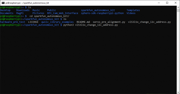
Inside the sparkfun_autonomous_kit directory is the vl53l1x_change_i2c_address.py example code. Execute the example code.
- Use the
ls command list the files in the directory and to verify it is there. - To execute the example code, run
python3 vl53l1x_change_i2c_address.py.
Execute the vl53l1x_change_i2c_address.py example code. (Click to enlarge)
- Follow the prompts of the example code. When selecting, which channel on the Mux to enable, select the channel that the VL53L1X ToF distance sensor is attached to (i.e. channels 0 or 4, from the instructions earilier). If users have successful performed the I2C address change, they should be able to test the sensor on the new I2C address. Once users are finished testing, use Ctrl+C to terminate the script.
Running the I2C address change code. (Click to enlarge)
- After the the test is complete, shutdown the Raspberry Pi using the
sudo shutdown now command as mentioned in the Software Overview: Part 1 - Raspbian OS section. (*Remember... before unplugging the power or removing the SD card, be sure to verify that the Raspberry Pi has completely shutdown to avoid corrupting the SD card.)
- Users should shutdown and unplug the Raspberry Pi before swapping the sensors.
![servo test assembly]() Shutting down the Raspberry Pi. (Click to enlarge)
Shutting down the Raspberry Pi. (Click to enlarge)![Pi Camera Assembly]() ACT LED indicating the end of the power down sequence, right before the power can be disconnected. (Click to enlarge)
ACT LED indicating the end of the power down sequence, right before the power can be disconnected. (Click to enlarge)
This completes all the hardware pre-test; please, move on to the Hardware Assembly section below.
Hardware Assembly
Note: Before assembling the SparkFun autonomous kit for the Sphero RVR, users should configure their Raspberry Pi and verify the hardware is working. (These steps can be performed with the kit fully assembled; however, avoid any unnecessary troubleshooting or pitfalls, it is recommended that the instructions be followed in the order presented.)
Now that we have verified that all the hardware is operational, let's assemble the SparkFun autonomous kit! To begin assembling the kit with the Sphero RVR, follow the corresponding guide.
Software Overview: Part 3 - Sphero SDK
Note: Users should use head over to the Sphero's
SDK webpage for details on the SDK's functionality. Additionally, Sphero also has a
support page in case users get stuck.
This section will focus on getting started with the Sphero SDK.
- To begin using the Sphero SDK, users should change the current working directory to the
sphero-sdk-raspberrypi-python folder using the following command:
cd ~/sphero-sdk-raspberrypi-python
- Once inside the
sphero-sdk-raspberrypi-python folder, users will need to spawn a shell in a virtual environment using the pipenv shell command.
- This will create a virtual environment if one doesn't already exist.
- This is the most important step to initializing the Sphero SDK; otherwise, users will run into issues executing any of the examples.
- After the shell has been activated, users can begin to start using the example code. Navigate around to find a code example.
- To run a Python example code, use the following command:
- Exiting:
- Use Ctrl+C to interrupt the keyboard control script.
- To exit the virtual environment shell, type
exit or Ctrl+D.
Examples
Keyboard ⌨️ Control & Camera Web Interface
This example will focus on getting the Keyboard ⌨️ Control example from the Sphero SDK working while streaming the Raspberry Pi's camera video feed. (*For more details on the Keyboard ⌨️ Control example, check out Sphero's webpage.)
To begin, users should remotely access the Raspberry Pi through the SSH protocol (see the Remote Access with SSH section).
Enabling the Camera
Once users have logged in, change the current working directory to the RPi_Cam_Web_Interface folder using the following command:
cd RPi_Cam_Web_Interface
Once inside the RPi_Cam_Web_Interface folder, users can utilize the following two commands to enable/disable the web service for the camera and pan-tilt servo controls.
- To enable the camera and servo controls, use the
./start.sh command. - To disable the camera and servo controls, use the
./stop.sh command.
After the web service is enabled, users can bring up a live stream of the video feed from the camera using a web browser on the remote computer. The url for the web interface is: <IP Address>/html (users can also use raspberrypi.local/html). If the url doesn't work, try adding the http:// prefix (i.e http://raspberrypi.local/html/).
Screenshot of camera web interface.
Users should then return to the home directory using either the cd ~ or cd .. command.
Keyboard Control
Note: Don't forget to move the serial switch on the Pi Servo pHat to RVR so that the serial communication passes through the 4-pin UART header for the Sphero RVR.
![]()
Move serial switch to RVR. (Click to enlarge)Next, to begin using the Sphero SDK, users should change the current working directory to the sphero-sdk-raspberrypi-python folder using the following command:
cd sphero-sdk-raspberrypi-python
Once inside the sphero-sdk-raspberrypi-python folder, users will need to spawn a shell in a virtual environment using the pipenv shell command (this will create a virtual environment if one doesn't already exist). This is the most important step to "initializing" the Sphero SDK; otherwise, users will run into issues executing any of the examples.
After the shell has been activated, users should move the current working directory to the keyboard_control folder using the following command:
cd projects/keyboard_control
Once inside the keyboard_control folder, users will need to start the drive_with_wasd_keys.py Python example code with the following command:
python3 drive_with_wasd_keys.py
You may see a few initialization printouts like:
Checking RVR firmware versions...
Checking CMS firmware versions...
Firmware check done.
Wait a minute or two for the script to finish initializing. Once complete, users should be able to use the W, A, S, D, and Space Bar keys to control the Sphero RVR.
Have fun driving the RVR around, don't forget to play with the servo controls on the web interface.
Exiting
Use Ctrl+C to interrupt the keyboard control script. The example code will then display:
Keyboard Interrupt...
Press any key to exit.
and prompt user to Press any key to exit.. Pressing another key will exit the script. To exit the virtual environment shell, type exit or Ctrl+D.
To disable the web interface, change back to the RPi_Cam_Web_Interface directory and use the ./stop.sh command.
Using Both VL53L1X Sensors
To use both VL53L1X ToF sensors, users will need to use the Qwiic Mux to access a single sensor and change the I2C address. Then users will need to access both sensors through the Qwiic Mux to retrieve the distance data. The following instructions will get users started on this process with the included example code.
To begin, users should remotely access the Raspberry Pi through the SSH protocol (see the Remote Access with SSH section).
Changing the I2C Address
The VL53L1X ToF distance sensor has a "software" configurable I2C address; however it is "volatile", upon re-powering the device, it will automatically reset to the default I2C address. This is where the Qwiic Mux comes in. It is used to isolate the sensors, initially, so that the I2C address of one of the sensors can be reconfigured on power up.
Once logged in, change the current working directory to the sparkfun_autonomous_kit folder.
- Users can use
cd sparkfun_autonomous_kit from the home directory. - Otherwise, user can also
cd ~/sparkfun_autonomous_kit from any other location.
Inside the sparkfun_autonomous_kit directory is the vl53l1x_change_i2c_address.py example code. Execute the example code.
- Use the
ls command list the files in the directory and to verify it is there. - To execute the example code, run
python3 vl53l1x_change_i2c_address.py.
Follow the prompts of the example code. When selecting, which channel on the Mux to enable, select the one of the channels that the VL53L1X ToF distance sensor is attached to (i.e. either channels 0 or 4). If users have successful performed the I2C address change, they should be able to test the sensor on the new I2C address. Use Ctrl+C to terminate the script.
Running the I2C address change code. (Click to enlarge)
Running the Example Code
Now that users have modified the I2C address of one of the sensors, they can use the example code to get readings from both sensor.
Inside the sparkfun_autonomous_kit directory is the hardware_pre_test folder. Change the current working directory to the hardware_pre_test folder.
- Use the
hardware_pre_test command.
Inside the hardware_pre_test directory is the VL53L1X folder. Change the current working directory to the VL53L1X folder.
- Use the
ls command list the files in the directory and to verify it is there. - Use the
cd VL53L1X command.
Inside the VL53L1X directory is the dual_sensors.py example code. Execute the example code.
- Use the
ls command list the files in the directory and to verify it is there. - To execute the example code, run
python3 dual_sensors.py.
Follow the prompts of the example code. When selecting, which channel on the Mux to enable, select both of the channels that the VL53L1X ToF distance sensors are attached to (i.e. channels 0 and 4). If users have successful performed the I2C address change, they should be able to designate the I2C address of the front and rear sensor. Once users are finished testing, use Ctrl+C to terminate the script.
Reading distances from both VL53L1X ToF sensors. (Click to enlarge)
Troubleshooting Tips
Do you think something is broken? Let's try some of these common troubleshooting tips before looking for technical assistance. This section is written in a hierarchical fashion to make it easier for users to follow from top to bottom. If you know what you are looking for an don't see it right away, don't forget to try a "Google" search; often, someone else has already run into the same issue and may have posted a solution.
First Things First
If you have never tried to troubleshoot a device before, this is a great beginners guide of common points that novices (and even some experienced users) should check.
Replacement Parts
In the event that you loose or break any parts, the components of the kits are linked below. (*Unfortunately, the mounting plate and 3/4" 4-40 standoffs for advanced kit are unavailable at this time.)
Replacement Parts
Click the button above to toggle a list of replacement parts that are available from our catalog.Main Components:
34 available
SEN-14722
This SparkFun Distance Sensor Breakout utilizes the VL53L1X next generation ToF sensor module to give you the highly accurate…
7Only 9 left!
GPS-14414
The SparkFun XA1110 GPS Breakout is a small I2C-supported module built for easy hookup, thanks to our Qwiic Connect System. E…
5In stock
KIT-15081
To make it even easier to get started, we've assembled this Qwiic Cable Kit with a variety of Qwiic cables from 50mm to 500mm…
1In stock
COM-15051
This is a class 10 16GB microSD memory card, perfect for housing operating systems for single board computers and a multitude…
In stock
DEV-14028
This 8mp camera module is capable of 1080p video and still images that connect directly to your Raspberry Pi. This is the plu…
9In stock
BOB-14685
The SparkFun Qwiic Mux Breakout enables communication with multiple I2C devices that have the same address that makes it simp…
Out of stock
ROB-14391
This is an easy-to-assemble pan/tilt bracket kit that utilizes servos to move on two axes fit for camera and helping-hand app…
4In stock
DEV-15316
The SparkFun Servo pHAT for Raspberry Pi allows your Raspberry Pi to control up to 16 servo motors in a straightforward manne…
115 available
PRT-14272
The Raspberry Pi Zero and Zero W are both equipped with a smaller CSI (Camera Serial Interface) port than on a full-sized Ras…
In stock
PRT-10369
This is a simple four wire cable. Great for jumping from board to board or just about anything else. There is a 4-pin JST RE …
Out of stock
DEV-15470
The Raspberry Pi Zero W is still the Pi you know and love, but at a largely reduced size of only 65mm long by 30mm wide and n…
1Mounting Components:
In stock
PRT-10453
There are your standard Philips-head 4-40 screws. They are 1/4" long and come in packs of ten. This is the screw size we use …
Only 9 left!
PRT-10454
We could talk about how the Zinc used in these nuts is only from the finest old-growth Zinc trees from across the globe and i…
Only 7 left!
PRT-10452
Standard Philips-head 4-40 screws. They are 1/2" long and come in packs of ten. This is the screw size we use in most of the …
In stock
PRT-10228
These are very handy. They are simple angle brackets with one threaded and unthreaded hole. Use them for connecting PCBs at 9…
Sphero RVR and SDK
For all things related specifically to the Sphero RVR and/or the Sphero SDK, head over to the Sphero SDK website. They have troubleshooting guides for the RVR and SDK software.
If you can't find the information you need in their troubleshooting guides, their community forum is a great place to find and ask for help.
Some quick tips...
The Pre-Configured Image
If you have accidentally erased you SD card, it has become corrupted, or you need to start from scratch...
the pre-configured image of Raspbian can be downloaded using the button below.
Remove Overclock
To undo the overclock configuration, modify the config.txt file using sudo nano boot/config.txt. Scroll down to the bottom and under [pi0w] change:
over_voltage=4
force_turbo=1
to:
over_voltage=6
force_turbo=0
(*More information on overclocking can be found on the Raspberry Pi Foundation's website.)
Custom Image
For users looking to build their own image, here are basic instructions. If you know what you are doing then these should be easy to follow. If you don't know what you are doing, download the pre-configured image. (*Assisting customers with building their own custom Raspbian image is beyond the scope of this tutorial and our technical support team).
- Follow the instructions on the Sphero SDK to download and setup the SDK software.
- Download and setup the
RPi_Cam_Web_Interface code from the GitHub repository. - Install the
sparkfun-qwiic Python package using pip3. - Download the SparkFun Autonomous Kit example code from the GitHub repository.
- Move the servo control firmware from the SparkFun Autonomous Kit example code to the
RPi_Cam_Web_Interface folder. - Modify the
start.sh and stop.sh bash scripts to use and terminate the servo control firmware. - Configure the SD card to overclock Raspberry Pi Zero Ws:
- Enable the required interfaces for the Raspberry Pi.
Testing the Hardware
Testing the hardware is a great place to start, there is an Initial Hardware Tests section in the guide for testing all the hardware included in these kits.
If there something you are trying to do with a specific piece of hardware, go back to the Initial Hardware Tests section to verify it is working with the example code. If the device is working with the example code, then there is possibly an issue with the code you have written. Otherwise, if the device isn't responding properly, users double check if any of the "tricks of the trade" (i.e. tips) below apply.
"Google" It!
Have you tried searching the internet? Often, with common issues, someone else will have run into the same issue and there will be a few posts on it with solutions, if not workarounds.
(*Search engines like Google are great resources! At SparkFun, we are a company of ~100 employees with only ~20 of us with technical knowledge. There ~7.7 billion people in the world and ~ 3.5 billion people with internet access. Obviously, not all of them will be technical experts; however, why not leverage these numbers in your favor?)
Weird Characters/Keyboard Map
If you are getting weird characters when typing, double check that the keyboard map is configure properly. You can set the localization and keyboard map using sudo raspi-config.
WiFi
Double check the WiFi network. As mentioned in the Configure the Raspberry Pi section, the Raspberry Pi Zero W supports 2.4GHz 802.11n wireless LAN and is only compatible with 2.4GHz networks. It will not connect to a 5GHz WiFi network.
If you are in an office or school setting, you may be on an enterprise network. Check with your IT network administrator, about making sure that you have the necessary permissions and configurations in place to utilize our kit.
Note: This kit doesn't actually need internet access to work. If you can get approval from your network administrator, you can run the examples from a basic home WiFi router. Just configure the router with an SSID and passphrase, then connect the remote computer to the router directly. You can then configure the Raspberry Pi to use the basic home WiFi router's network instead. (*The Raspberry Pi hosts the camera web interface internally.)
If you have multiple Raspberry Pi's on a single network. Try powering the rest off and just using the Raspberry Pi you are trying to troubleshoot. This should isolate any bandwith issues that may occur if you have too many devices connected to the network at once.
Use the WiFi router's network monitoring tools to verify that the Raspberry Pi and the remote computer are on the network.
Try to ping the Raspberry Pi or ssh in. Try using both the IP address and raspberrypi.local methods.
ping <IP Address>ssh <IP Address>ping raspberrypi.localssh pi@raspberrypi.local
Re-enable the serial console/login shell. Using an SD card reader, add console=serial0,115200 back to the cmdline.txt file on the SD card. Then use the Pi Servo pHat for the headless setup.
- Double check the IP address. Also, try to ping the router, the remote computer, and/or a website to check for any network issues.
ifconfighostname -Iping <IP Address of Remote Computer>ping <IP Address of Router>ping google.com
- Check the
wpa_supplicant.conf file. Do you have the correct country code in?
sudo nano /etc/wpa_supplicant/wpa_supplicant.conf
If your Raspberry Pi isn't connecting to the WiFi network, you should re-configure the WiFi. Even if you know you have setup the credentials properly, it was working prviously, or it is on the network... sometimes, it is just as easy are resetting the WiFi configuration. Users should try both the wpa_supplicant.conf file and raspi-config tool methods.
Camera Focus
By default the camera lens should be screwed in with the focus set to ∞. Although it is not advisable, the sensor can be refocused.
- This will void any warranty on the product, and you will NOT be able to return the camera module.
- You should avoid this as it can damage the sensor and/or possibly loose, break, or scratch the lens.
- To refocus the lens, carefully twist the lens at the indentations.
Serial Connection
If you are having serial connection issues with the Sphero SDK:
Cable Issue?
Test the serial port on the Raspberry Pi, re-enable the serial console/login shell.
- Using an SD card reader, add
console=serial0,115200 back to the cmdline.txt file on the SD card. - Then use the Pi Servo pHat for the headless setup.
If the serial port on the Pi works, it may be an issue with the UART cable. Try testing for continuity with a multimeter.
Qwiic Issues
If none of the Qwiic (I2C) devices are responding or you get an IOError, this may be an I2C issue.
- Double check that the I2C bus is enabled on the Raspberry Pi using the
raspi-config tool. - You can also ping the I2C bus using
i2cdetect -y 1. - Test the hardware:
- Double check the Qwiic cables are inserted properly.
- Try testing devices individually following the Initial Hardware Tests section.
- Time to bust out that dusty multimeter. Are they at least getting power?
- Try swapping the cable, maybe one of your cables is bad.
- Use a multimeter to double check the continuity on the I2C lines and power.
GPS Lock/Accuracy
The GPS needs a view of the sky; check out our GPS Basics tutorial.
- If you are indoors, the GPS satellite signals will not reach the modules.
- If you are near a window, you may get some readings, but they will not be accurate.
- If you are in an urban/city environment, you may have issues with accuracy near tall objects like trees or buildings. This is due to the signal reflection off these objects.
- The triangulation calculation requires precision timing, that is why there atomic clocks on each satellite. Any slight deviation, including the reflection of a signal, will throw off the position calculation.)
If you the PPS LED is blinking, but you are not getting any positional data you may not have a lock from enough satellites. The PPS LED doesn't guarantee a positional lock, based on the datasheet, it usually indicates a NMEA sentence was received at some point.
The Titan X1110 receiver is only compatible with GPS and GLONASS satellites.
Servo Inconsistency
My servo is behaving inconsistently... unfortunately, these are inexpensive servos. (*The Pan/Tilt Bracket Kit costs ~$7. Standard servo costs ~$25-40/each on average.)
- Things like jiggling and slow movements can be expected. This usually occurs because the manufacturing tolerances are low for the potentiometer and gears, used inside. If your servo is acting "all sorts of crazy" when testing with the example code... ok, then you probably have a bad servo; reach out from the technical assistance page.
- Stripping the servo gears and damaging the servo can happen when the servo is forced into a position or manually moved (while powered or connected to the Pi Servo pHat).
- Missing the correct servo horns or screws? This happens from time to time, reach out from the technical assistance page.
- Users can upgrade their pan-tilt servo assembly if they would like to use a more reliable system. Just make sure the replacements have enough space to move, the camera cable is long enough, and that it is compatible with the mounted servo horn (or mounting holes).
VL53L1X
Performance
The ToF sensor does have performance limitations. For example, the sensor FOV, the target properties (i.e. size, color, reflectivity, etc.), and the ambient light all affect the sensor performance and reliability. Check out these related support articles from Garmin:
I2C Address
The VL53L1X does not permanently store any I2C address changes. On each power up cycle, the sensor reverts to the default I2C address. (*There is no work around... we have already asked the manufacturer. That is why the Qwiic Mux was added to the kit.)
Still Stuck?
Need help?
If your product is not working as you expected or you need technical information, head on over to the SparkFun Technical Assistance page. Otherwise, if you have already tried the troubleshooting tips above, the SparkFun Forums are a great place to find and ask for help. (If this is your first visit, you'll need to create a Forum Account to post questions.)
Resources and Going Further
For more information on the SparkFun Autonomous Kit and the included hardware, check out the resources below:
GitHub Repositories:
Hardware:
Software:
Product Showcase Videos:
ReadtheDocs for Python Modules:
Sphero Resources:
Hardware Hookup Guides:
Qwiic Distance Sensor (VL53L1X) Hookup Guide
The Qwiic VL53L1X time of flight sensor is capable of several modes, as well as having a range of 4M. Let's hook it up and find out just how far away that thing over there is.
Qwiic MUX Hookup Guide
Have a bunch of sensors with the same I2C address? Put them on the Qwiic MUX (TCA9548A) to get them all talking on the same bus!
Interested in other robotics projects? Check out some of our robotics related tutorials below:
Experiment Guide for RedBot with Shadow Chassis
This Experiment Guide offers nine experiments to get you started with the SparkFun RedBot. This guide is designed for those who are familiar with our SparkFun Inventor's Kit and want to take their robotics knowledge to the next level.
SparkFun Line Follower Array Hookup Guide
Learn how to connect the RedBot Line-Following Sensor Bar to an Arduino-type microcontroller. Use the example sketches to read data from the bar, and try out a simple line-following algorithm.
Light-Seeking Robot
We use parts from the SparkFun Inventor's Kit v4.0 to create a light-seeking robot that mimics the behavior of single-celled organisms.
Assembly Guide for SparkFun JetBot AI Kit
Assembly Guide for the SparkFun JetBot AI Kit. This tutorial includes photos & comments to assemble the two-layer chassis & additional components unique to the JetBot kit.
learn.sparkfun.com |
CC BY-SA 3.0
| SparkFun Electronics | Niwot, Colorado


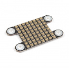


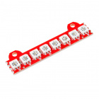
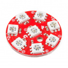


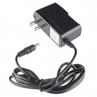
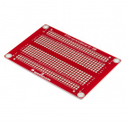
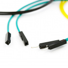
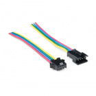


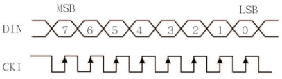
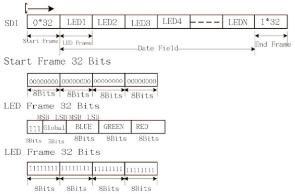


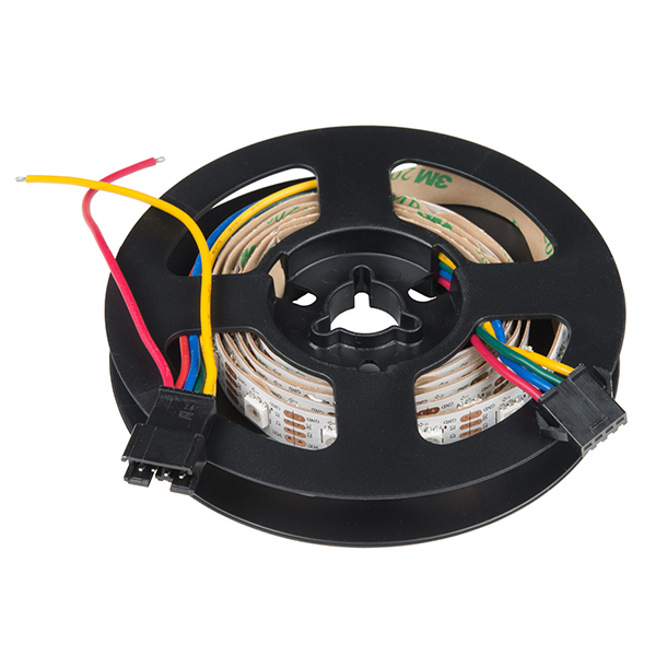


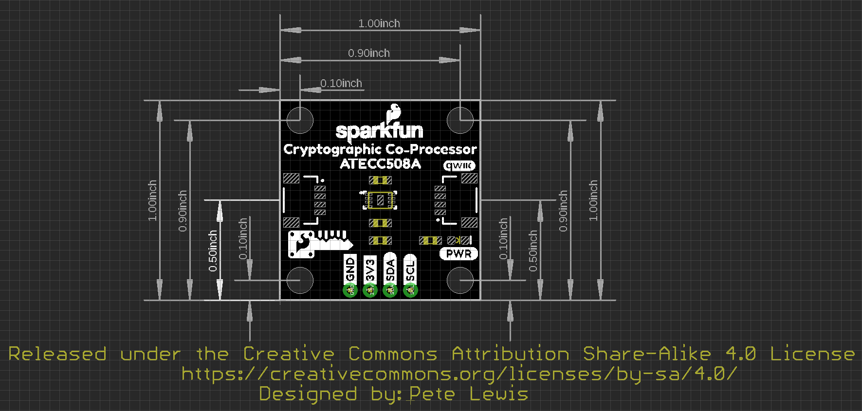

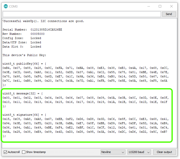


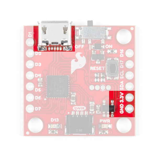

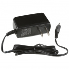
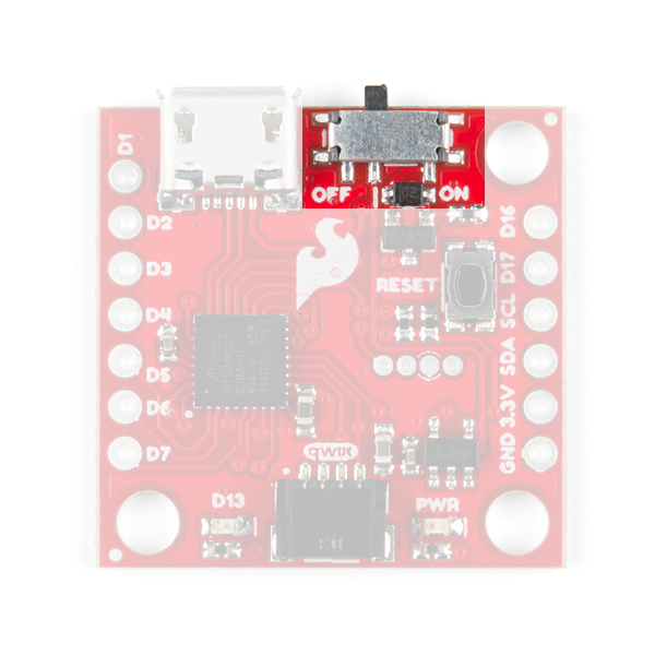

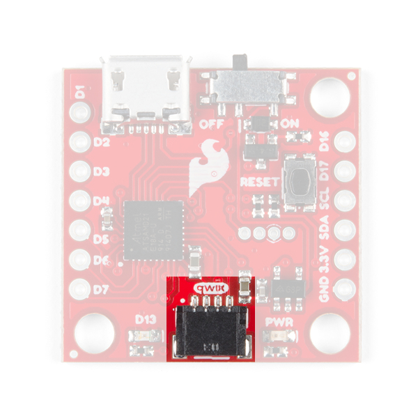
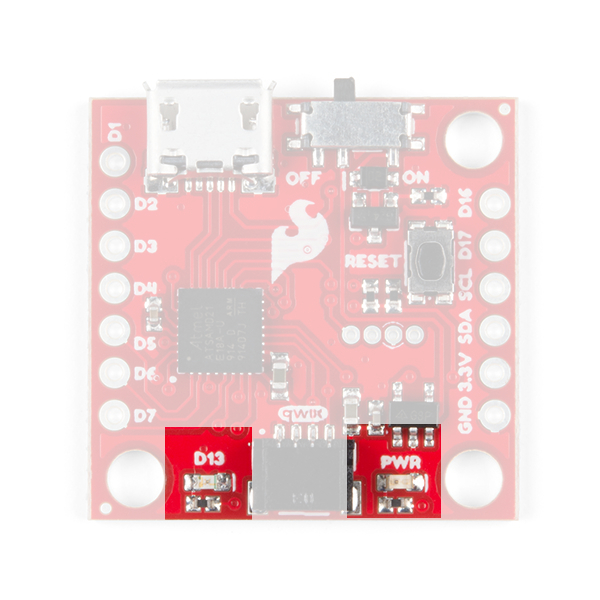
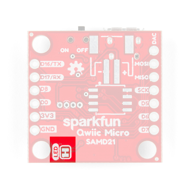
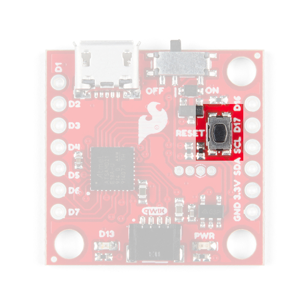
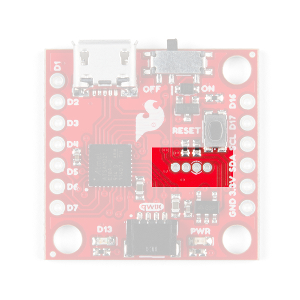


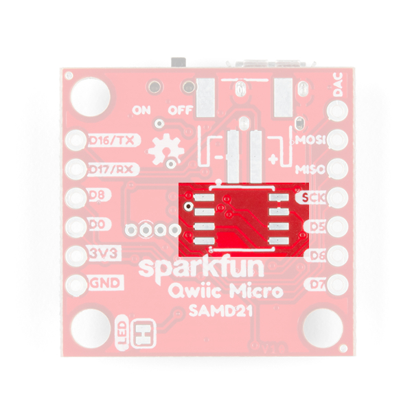


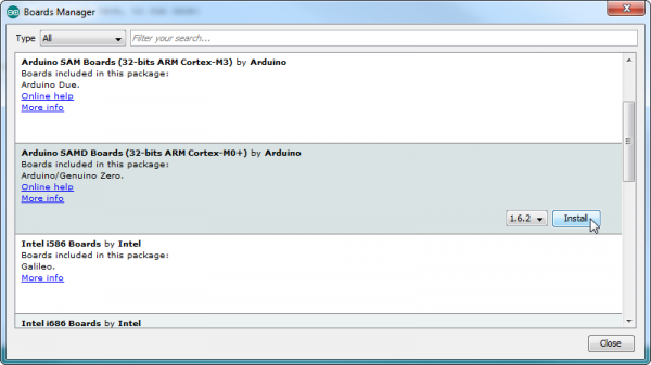
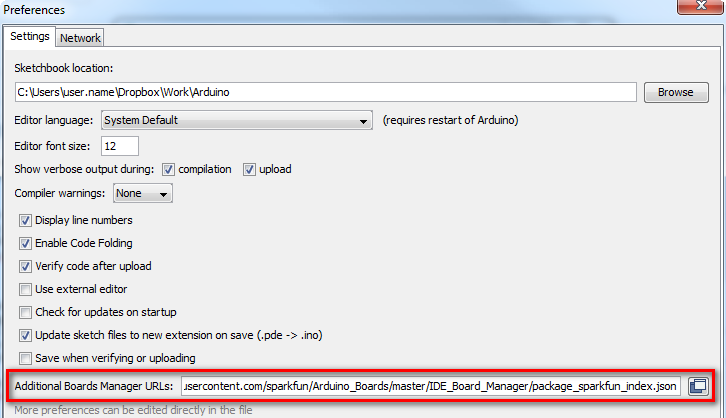


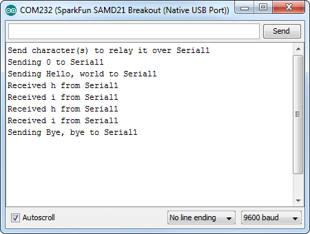

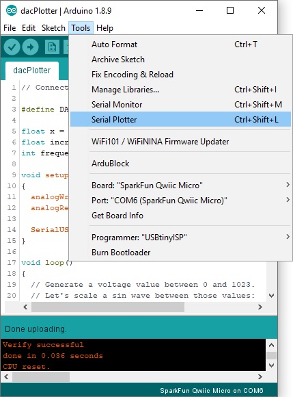
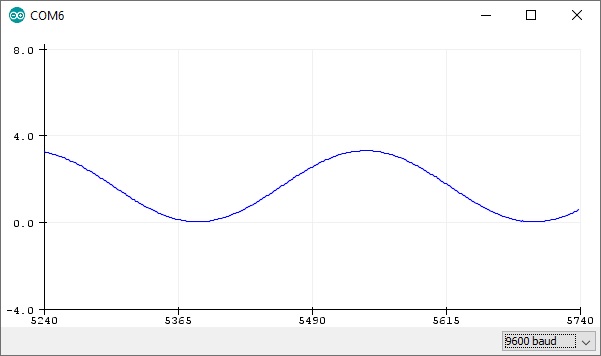


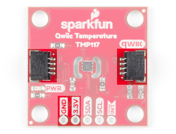
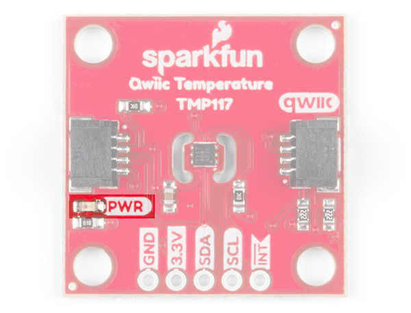
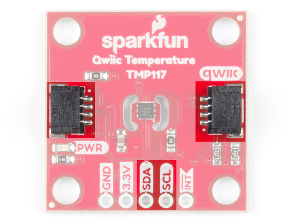
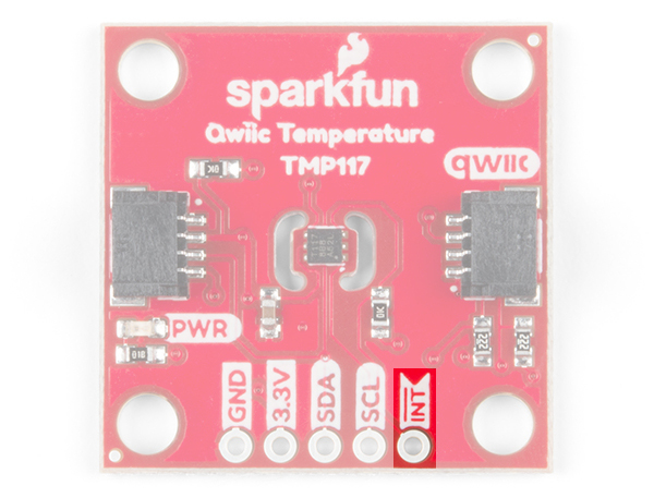
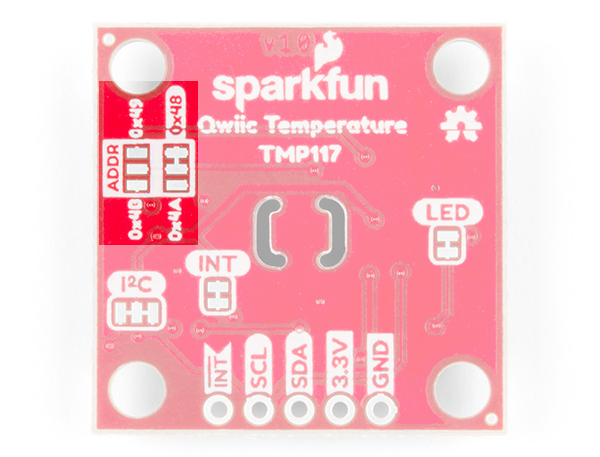
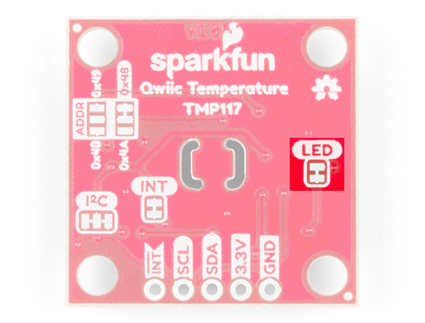
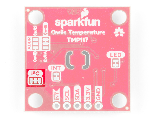
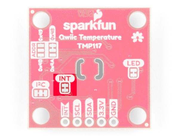


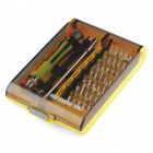


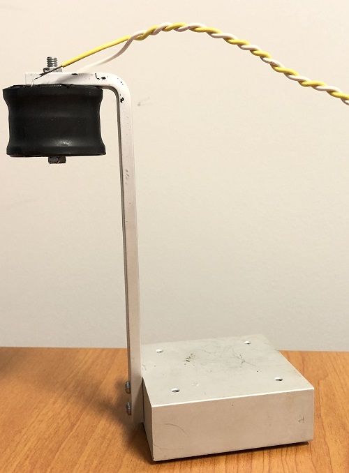
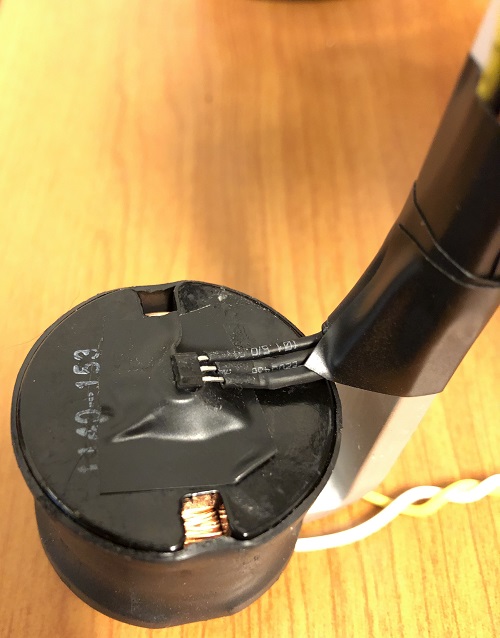


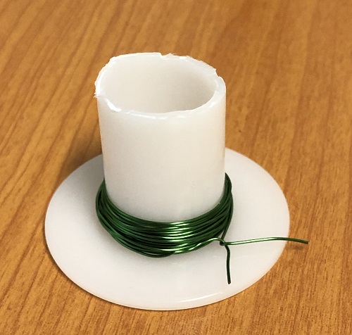
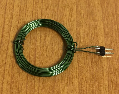
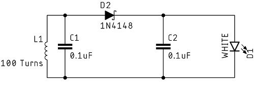


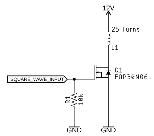
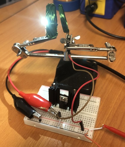

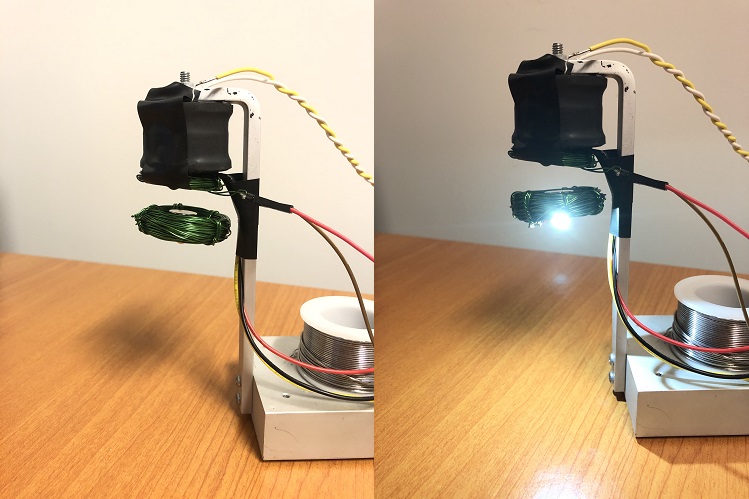


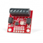
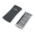


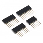

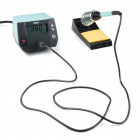

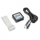
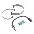
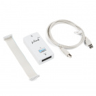

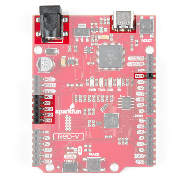

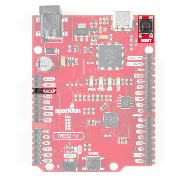
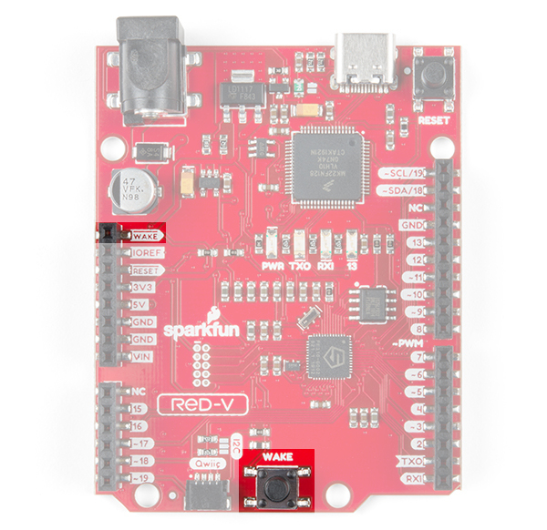
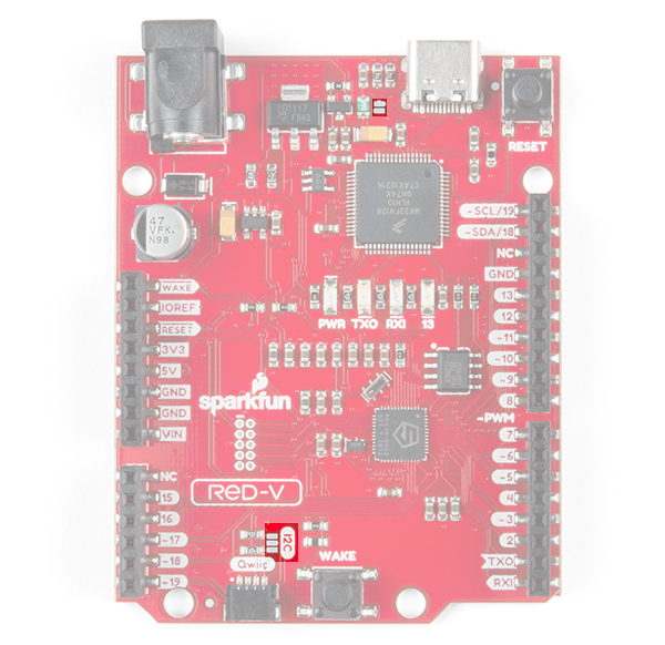


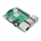
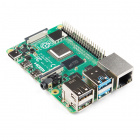
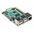
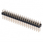
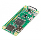
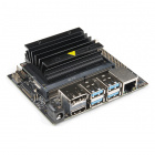
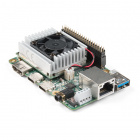
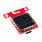

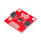


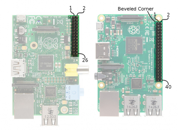


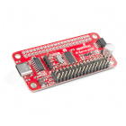

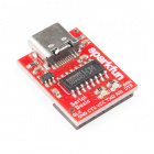
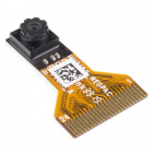


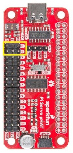

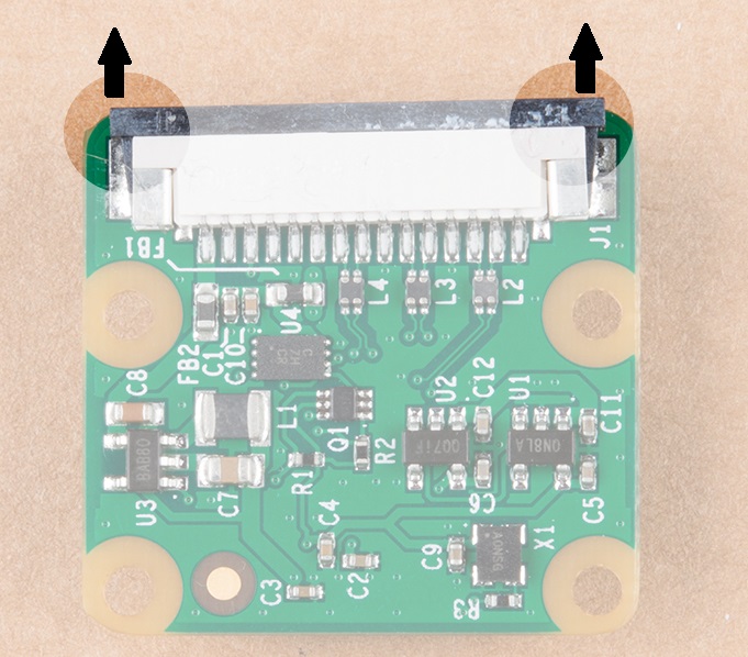


")